Embed Size (px)
Citation preview

61
May1988
ISSN 0970-3993
INDIA Rs. 8.00
©lc RI1C0COMPUTER CONTROLLED SLIDE FADER
Radio communications of the future
A new multilayer process forintegrated passive devices
Parametric equaliser

Publisher: C.R. ChandaranaEditor: Surendra lyerTechnical Editor : Ashok Dons,Circulation: J. °hesAdvertising: B.Nt. Nish.Production: C.N. INithegari
Address.ELEKTOR52,
ELE CTRO NICS1,4 LTDO7 INDIA
TeleC P0111176 661. aEe.n
Overseas edRion,
oo
:Vat
9E
MEMBER
Printed et : Tn. OffsetBombay - 600 013
4923281, 6.21354
Copyright 1918 Elektuur B V
eeteeGls
CONTENTS
Editorial
All in one .
Volume -6 Number 5May -1988
Components
A new multi layer process for integrated passive devices
Computers
Computer management systems take over .....
Second generation programmable logic ................
PROJECT: Stereo sound generator .
Test & Measurement
Dual trace oscilloscopes: a review (Part -5)
Audio & Hi -F1
PROJECT: Parametric eguiliser
Radio & Television
PROJECT: Tuneable preamplifiers for VHF and UHF TV
Radio communications for the future
5.05
5.21
5.25
5.32
5.29
. 5.36
5.44
5.General Interest
PROJECT. Computer controlled slide fader (1) 5.52
Information
Telecommunication news
Electronics news
New ProductsAppointments
Guide lines
Index of advertisers
Sslein3.1
PROJECT: Tormentor .............
5.17
5.113
5.60
5.71
5.74

e\-19c-seva
Front cavilExperimental set-up of fourslide projectors driven by thecomputer -controlled slidefadder described in our issue.
ALL IN ONEThe age of too -in -one' and 'three -in -one', a combination of radio andcassette player, Is being replaced by the lour -in -one: A wristwatch isnot a mere wristwatch anymore. A Japanese firm has introduced awatch with which you can talk! The gadget can decipher your voiceand understand your queries. Of course, the gadget should be madefamiliar with your voice so that it can synthesise the characteristic notesand use the data as a dictionary for decoding the speech.
Dr. Raj Reddy of Carnegie Mellon University, whose talk on robotics Iscovered elsewhere in this magazine, has gone one step further. tieinforms us thatthe Japanese technology now has the limitation thatthewatch cannot understand the language If someone other than theowner spoke to it, unless it is re -tuned. Carnegie Mellon has developeda technology which is 'speech -Independent', meaning the gadgetcan understand anybody's talk
The profound changes in the technology of computer, communicationand Artificial Intelligence is bringing about a metamorphosis. Thus, theconcept of a four -in -one is a distinct reality, There will be a portableelectronic office. A small gadget will have audio and video facility. inaddition to functioning as a computer, enabling, data, video andvoice transmission.
The idea of a phone in evew home will be replaced by the slogan, aphone In every pocket ibis micro -gadget can store a 100 pages of adaily newspaper.
Should you think these are exotic gadgets meant only for Japan andthe US, you are mistaken. As Dr Reddy predicts, low -power, battery -operated, cheap computer will dominate the future and the computerwill have both speech and visual facilities enabling even an Illiteratevillager to use the gadget. Less sophisticated the person Is, moreSophisticated the machine will be.
If transistors, Iwo -in -ones, colour TVs and electronic telephone couldmake Inroads Into our villages, the days of four -In -one computers,functioning at the village panchayat office cannot be far behind.
ise list 5.05

TELECOMMUNICATIOPI NEWS TELECO
LAUNCH OF IRS
With the launching of the indigenously -built remote sensing satellite IRS -IA,India has joined the select group of na-tions, the USA, the USSR, France andJapan, in having such a sophisticatedfacility. India is the first developing coun-try to have a remote sensing satellite.IRS -IA, weighing 980 kg, is the heaviestsatellite to be built by India and it is hertenth one to be put in orbit.
Placed M polar sun -synchronous orbit,the satellite will cover the entire Indiansub -continent once in 22 days and help inthe study of natural resources during var-ious seasons under identical conditions.The satellite is orbiting the earth over thepoles at a height of about 900 km, taking103 minutes for each orbit.
The IRS -IA carries three linear imagingand self -scanning cameras which takepictures of 148 km -wide scenes in fourdifferent colours. The data will be re-ceived at the ground station nearHyderabad. The satellite will pass overIndia seven to eight times a day with eachpass having a duration of five to ten mi-nutes. The data sent down will be equi-valent to some 4000 volumes of 300pages each, roughly a good sized libraryof about 10,000 books each day. The Na-tional Remote Sensing Agency,Hyderabad, will receive, process anddistribute the satellite data to severaluser -agencies within India and abroad.The IRS -IA is designed to operate for aminimum of two years. IRS data will bevital in areas like agriculture, forestry,geology and hydrology and its datawould be the key element in the NationalNatural Resources Management Sys-tem.
The satellite IRS -IA was the seventh tobe launched with foreign launchers andthe fourth to go up from the SovietUnion. The other three satellites whichwere launched from the Soviet Unionwere Aryabhata (1975), Bhaskara-I(1979) and Bhaskara-II (1981). The In-dian National Satellites (INSAT-IA andIB) were launched from the UnitedStates. India's first experimental com-munication satellite, APPLE, waslaunched by the European SpaceAgency.
LOW-COST EARTH STATIONS
The International Maritime Satellite Or-ganisation, Inmarsat, has approved the
trial use of limited capability earth sta-tions (LCES) for the provisioned telexservices to ships and possibly othermobile units. The new stations couldproside easy access to the Inmarsat satel-lites particularly for the developingcountries and from areas where the exist-ing teldcommunications infrastructure isinadequate or traffic requirement is
fairly low.
Currently operating earth stations withInmarsal satellites are substantial andexpensive installations. With large,steerable, parabolic antennas, averaging13 metres in diameter, and the capacityto handle a large number of simultane-ous voice, data and telex calls, they costseveral million dollars to build. Thereare now 20 such stations in the Inmarsatsystem, owned and operated by telecom-munications authorities or companies inthe countries in which they are located.
The new earth station will have an an-tenna of less than one metro in diameterand it will handle only a single telex com-munication channel at a time. It will op-erate in effect as a ship -to -ship fink,through a main coast earth station. TheInmarsat council has agreed for a lowersegment charge because of the restrictedrequirement of LCES.
SATCOM IN BALLOON
The National Aeronautics and Spa.Administration of the US will use sat -coma in a space project. The Inmarsatcouncil has approved the installation of amodified ship earth station on a high -al-titude balloon.
The SES will be carried on a "Supernovalong duration space balloon flight". Theballoon, which will carry equipment forobservation of a large supemova visiblefrom the southern hemisphere, will usethe satcom terminal for transmission ofobbervafional and navigational datathrough its light. The balloon will travelfrom Australia to Brazil in a journey last-ing seven to ten days at heightg up to 40km, an altitude at which satcoms had notbeen used before.
The satcom terminal is being supplied bythe US firm, Radar Devices, under acontract worth 27,000 dollars. It will be amodified form of the firm's satcoms shipearth station, normally sold to ships andyachts for communications through theInmarsat system.
The satcom unit will transmit 20 minutedata stream every four to six hours via
Inmarsat satellites to computers at theUniversity of California's Centre for As-trophysics and Space Selene.. Scientistswill use the positioning data to make di-rectional changes in balloon course,which will maximise the observationalopportunities.
EUROPORT '87
Europort '87, held in Amsterdamshowed the latest developments in el. -trollies for shipping and it was evidentthat movement towards electronics atsea is gathering force.
In Satellite communication, the main at-traction was Standard -C which made adebut. Standard -C offers all satcomsfacilities except voice over a tiny om-nidirectional antenna. Thrane andThrane of Denmark is a forerunner inthis field. The firm, STC, showed a mockup of a Standard -C. Marconi was dis-playing nweIchshihpas girth station,
rigid antenna (00 kg). Its tafgei is theyacht market.
The newly unveiled transportable ver-sion, Satpax, which is packed in twocases weighing 20 kg and 40 kg respec-tively also made its entry. A third case tocarry the plug -ins such as computer, fac-simile, nod UHF/VHF patch is also pro-vided. Airdrop cases are offered and thewhole system is designed to a militaryspecification.
On display for the first time were twopublic phones which Comsat is promot-ing for use with the Inmarsat system. Acredit card phone began extended trialsin 1987. Interest has already been shownby cruise ships and offshore installations.Alongside was the system without creditcard slot, dial or keypad. Here the calleris automatically connected to theoperator at one of Comsat's earth sta-tions and gives a card number or homephone number debit the charges beforebeing connected manually. A numberofother value-added services were beingpresented by Comsat, including an elec-tronic mailbox facility called Seabox, apacket -switching service, and a chequingfacility, Cashcall, which uses a des,iceto check a caller's account and printout a cheque for cashing on board.
NO MORE NIGAMS
The Department of Telecommunica-tions does not favour the idea of creatingmore corporations like the. Mahanagar
nee 5.17

TELECOMMUNICATION NEWS TELECO
Telephone Nigam Ltd. Instead, it prop-oses to accord greater financial au-tonomy and decision -making powers totelephone exchanges M major cities andtowns.
The main reason for dropping the crea-tion of nigams for big cities is that theseare major revenue earning centres.Without these centres, network of smal-ler cities and town, would be starved offunds. Also, the government would besaddled with loss making centres, whilethe revenue earning centres would be
taken away in the form of autonomouscorporations.
The department is considering a prop-osal to set up a separate financing agencyfor the telecommunication sector with aview to borrowing funds from the marketfor the entire telecommunication sector.
DELAY IN RAX
The scheme of introducing a meal au-tomatic exchange (RAX) a day fromApril 1 is likely to be delayed by at leastthree months. The delay is mainly due to
the non -availability of required numbeof units.
The unpreparedness of the seven RAXproducers who have been given licenceto produce them, DOT's delay M grant-ing environmental clearance for testingthe units developed by the C -DOT andthe delay in identifying suppliers of backup components were among the othercauses resulting in the postponement ofthe scheme.
ELECTRONICS NEWS ELECTRONICS NNIC OUT OF DOE
The National Informatics Centre (NIC)of the Department of Electronics hasbeen shifted and attached to the Plan-ning Commission. Dr. N. Seshagiri, di-rector-general of NIC, who was report-ing to the minister of science andtechnology now reports to the planningminister. Subsequent to this major pol-icy change, the DOE has been reor-ganised. A financing agency for elec-tronics has been cleared by the govem-ment in principle.
The shifting of NIC from DOE was in-evitable because of its growing size.About 2000 experts work in NIC which isresponsible for 57 departments, in addi-tion to advising all the state goyernments. The centre would bring 439districts in the country under its satellitecommunication network.
The union cabinet and the ElectronMsCommission felt that either a separatedepartment should be created for NIC orit should be attached to a suitable minis-try. Hence, it is attached to the PlanningCommission. The Planning Commissionhas to formulate the eighth five-yearplan in a more relaistic manner with datafrom the districts. NIC, with its vast net-work, will provide the input to the com-mission.
Following the reorganisation, DOE willhave 14 divisions. The materials andcomponents division will have three sun -groups namely microelectronics group,components group and special projectsin components. The second division willbe consumer electronics division. Con-
trol and instmmentation division willlook after power electronics, instrumen-tation and capital goods. The fourth willbe the computers and communication di-vision. This division will look aftersoftware development, computer aideddesigns and aural information system.
Other divisions are strategic electronics,information, planning and analysis, lib-rary and publication, manpower de-velopment, industry promotion,technology development, appropriateautomation promotion and microproces-sor application.
BOOST TO HI -TECH
The Department of Electronics willlaunch a special drive to increase invest-ment in the high-tech electronic compo-nents sector. Despite liberalised invest-ment conditions, the private sector failedto set up hi -tech components units,which have an export potential. Now, in-vestments are likely to be made in thepublic sector.
The seventh plan envisaged a turnover ofRs. 40,000 mores in the electronics sec-tor and components accounted for one -fifth of this. To achieve this target, an in-vestment of Rs. 850 crores was expectedin the components sector. But, privateunits cocentrated only on consumeritems like colour picture tubes and glassshell.
The DOE is now malting efforts to en-sure that the investments are made inareas such as manufacture of bi-polarICs, multi -layer PCBs and surfacemounted devices. State electronic corpo-
rations would be encouraged to takethese areas. Banks have been advised toprovide finances to manufacturing thesedevices rather than supporting the im-port of electronic goods,
The DOE has also plans to upgrade theSemiconductor Complex Ltd., Chan-digarh, for which an allocation of Rs. 11crores has been made. Emphasis will begiven to products which have ready mar-ketability and export potential. Initially,requirements of calculators and telecom-munication industry will be met. The de-partment has approved the setting up oftwo calculator units for manufacturingtwo million calculators.
C-DACT AFTER C -DOT
The proposed Centre for AdvancedComputing Technology (C-DACT) willhave the development of a supercompu-ter within five years as its major objec-tive. The goal is to make a machine witha peak computing power of 1000 megaf-lops within three years. Based on thisparallel processing computer, a fifth gen-eration computer system will be de-veloped with a rating of one to ten mill-ion logical inferences per second (LIPS)in five years. The initial funding of theproject, to be made by the Departmentof Electronics, is about Rs. 37.50 crores,including foreign exchange worth Rs.12.50 crores.
GDACT, besides the computer project,will take up commercial products such asVLSIs and chips for personal computers,advanced board level products. parallel
5.18 ...rms. on, ?ea

ELECTRONICS NEWS ELECTRONICS Nprocessing workstations and softwareproducts.
Under the Administrative control of theDOE, C-DACT will be a permanent sci-entific society and it will be modelledafter the Centre for the Development ofTelernatics. Dr. Vijay K. Bhaktawar, adirector in DOE, will be its first execu-tive director. Mr. K.R. Narayanan,minister of state for science and technol-ogy, and Mr. Sam Pitroda, adviser to thePrime Minister en technology missions,will be chairman and vice-chairman re-spectively of the governing council of theC -DACE.
Other members of the couaril includeMr. K.P.P. Nambiar, secretary, DOE;Dr. Vasant Gowarikar; secretary, DST;Dr. R. Narasimha, director, NationalAeronautical Laboratory; Prof. B. Nag,director, ITT, Bombay; Prof. V. Rajara-man, Indian Institute of Science, Banga-lore; and Dr. A Paulraj, Defence Re-search and Development Organisation.The existing supercomputer project andthe fifth generation computer project atvarious centres like IIT, Madras, NAL,Bangalore, TIFR, Bombay and C -DOTwill be co-ordinated by C-DACT.
In another development, the EarctronicsResearch and Development Centre ofthe Kerala government at Trivandrumwill be taken over by the DOE. TheERDC will be developed as a regionalcentre. The DOE is taking over thecentre as the state government is unableto find sufficient funds for the centre.
MICROELECTRONICS
An empowered committee of the goy-emment of India on the microelectronicspolicy has suggested that indigenous de-signs should be protected from karma -done] competition through fiscal men -
The committee set up by the DOE hasrecommended that design centres be setup with protoyping facilities near elec-tronics industry clusters. The committeehas also favoured commercial interac-tion between the chip manufacturing andassembly units and the industry.
The expert group has laid emphasis onimproving the comperetive strength ofthe microelectronics manufacturers bygiving them fiscal support. Investors areshy of entering microelectronics, fearinginternational competition.
The special group was set up by the gov-ernment to evolve a separate microelec-
tronics policy as this sector was sot grow-ing in the country. While microelec-tronic devices are used in the developedworld to the extent of 12 per cent, inIndia it is hardly one per cent.
NUCLEONIC WEIGHER
The Indian Institute of Technology,Bombay, has successfully tested andcommissioned a microprocessor -basednucleonic weigher for use on conveyorbelts to measure weight of materials likecoal, coke, fertiliser, lime stone, iron oreand so on.
Conventional weighing machines usingload cells encounter errors of the orderof plus or minus 10 per cent. Nuweighertechnique, being a non -contact method,sustains the precision on measurementover very 'long periods withe the errornot exceeding plus or minus half a percent. This is a radioisotope device for in-dustrial application.
The application of microprocessor hasmade the unit intelligent in that a singleunit by suitable software can use diffe-rent isotopes like cobalt -60 Caesium -137or Barium -132, corroded for decay andprint out the total weight of regular inter-vals on command. A single central pro-cessing unit can monitor five or morebelt conveyor systems every second andlog the weight.
The technology, developed by Prof. B.S.Magal and Prof. V.P. Sundersingh ofIIT, Bombay, is available for commer-cial exploitation from the deem (R & D),IIT, Bombay.
MANAGING TECHNOLOGY
A telephone and a television in awristwatch, a cheap and simple compu-ter that can be used by a villager, amachine replacing the mother's womb togrow a foetus, a dietary pill as substitutefor food, a non -vegetarian tomato, pro-duced by cloning the gene of a calf withthat of a tomato -these are products ofemerging technologies in the next twodecades. How will a professional man-ager cope with this change and exploit it?The Indian Institute of Management,Ahmedabad, to mark its silver jubileeyear organised a seminar entitled "Man-agerial Response To EmergingTechnologies" in Bombay.
An expert in each field namely, Roboticsand Artificial Intelligence, Electronicsand Information Technology, Plasticsand Petrochemicals and Biotechnology
delivered a talk.Mr. V. Krishnamurthy, chairman, StarAuthority of India Ltd., andTechnologyInformation Forecasting and Assess-ment Cell, in his keynote addresspointed out that success depended not somuch on the capital or hardware equip-ment but on the technology we posses-sed. Technological strength charac-terised the emergence of new economicpowers like Korea, Japan and Taiwan.Pleading for a phased tecluiologicalchange with a phased upgradatarn of thehuman resources, Mr. Krishnamurthysaid: "We cannot move from primitivedata entry machines to sophisticated,satellite -based computer networks over-night."The chairman of Electronics Commis.sion opined that government should notrun the industries and leave them to theprivate sector as the government was in-herently not suitable to manage the in-dustry. The private sector would perish ifit was inefficient.
Indian industry, having enjoyed the lux-ury of protected environment, foughtshy of facing challenges. Managersshould acceptcreative as the success or failure de-pended on the timely action taken bythem, Mr. Deodhar said.
Dr. Raj Reddy, university professor ofcomputer sciences and robotics and di-rector of the robotics institute, CarnegieMellon University, said the power ofcomputers had increased 1000 -fold in thelast few years. If the automobile industryhad progressed at the same pace, a RollsRoyce would have become available forfive dollars and it would have had aspeed of 50,000 miles per hour, running500,000 miles fora! litre of petrol.
A supercomputer, now costing 10 mill-ion dollars may be available for a mere10 dollars in the next 10 years. Thetechnology is changing at such a fastpace, that the limitk of physical lawswould be reached in the next 20 years,leaving no scope for new developmentthereafter.At Carnegie Mellon an automobile thatdrives itself is being developed. It hastwo stereo cameras to detect millionpixies. For this computation, at least atrillion operations would be needed,coupled with 1000 computer instruc-tions. To make the car take you to yourhome on its own, 10 billion operationswould have to be carried out, Dr. Reddycited as an example.
*or me. myna. 5.19

ELECTRONICS NEWS ELECTRONICS N
Self-operating, multipurpose micro fac-tories will be the mainstay of industriesin future. These factories, based on com-puters, would accept designs, get in-structions through satellite and producethe goods locally. Problems could be sol-ved by contacting the computer and ex-perts need not fly to carry out repairs.High quality products can be made hereusing computer, communication andknowledge industries, employing localtalent and labour. This will lead to mini-mal inventories, while capacity will bestockpiled.
This technology, however, may result ina social problem. Low-cost labour willbecome increasingly unimportant. Lossof manufacturing jobs will be likely. But,what kind of new jobs would emergecannot be even imagined today.
Computer -aided simultaneous engineer-ing will enhance production capability.Rapid redesiging and prototyping will
reduce costs. Large automotive man-ufacturing companies spent 100 weeks tomake a new car lamp in the US while theJapanese did it in 50 weeks. Preparationof a plastic lens for the lamp involvedtime consuming, tedious study. Instead ofthe normal six days, a computer does it in10 hours now. Tooling for injectionmoulding dyes used to take six to 12weeks in the past. Now, computer -aideddesign and manufacturing enables thedyes to be made in less than 24 hours.
The managerial problem now and in fu-ture will be to react to trends and cus-tomers' response quickly. The industrycannot survive if customers'need is notrapidly satisfied. This implies that cus-tomer response should be obtained al-most every day. Short -cycle innovationto bring the products out quickly will be-come indispensable. Reverse engineer-ing will be the strategic point in future R& D and the workforce must be suitablytrained to become expert reverse engin-
Thirly million TDA4600sSeven years ago, Siemens found a way ofintegrating the control circuit for switch -mode power supplies used in TV sets ona single 7 mm' chip. Since then, salesfigures have reached 30 million for thebipolar TDA4600 and 10 million for theTDA4601 version (with extended voltagerange: 80-270 V).Its ability to produce the requiredvoltages at varying input voltages and
loads in an economical way has madethe TDA4600/4601 the unrivalled topproduct on the market, favoured bymore than 200 customers throughout theworld. An enhanced version, theTDA4605, using "Sipmos" transistorshas now reached the production stage.As early as 1972, engineers at the Appli-cations Research Laboratories ofSiemens had conceived the idea of usinga flyback converter as a power supply forTV sets. Until then, the standard prac-tice had been to provide a rigid, andcost -intensive, coupling with the line fre-quency circuit. The introduction of theflyback converter drastically reduced thecircuitry and components. The inte-gration of the entire control circuit onthe TDA4600 further simplified thepower supply section in the TV set. Theimproved reliability of power suppliesequipped with the TDA4600 is reflectedin the significant reduction in TV setfailures over the past several years.
New VME board fromNationalNational. Semiconductor have intro-duced a high-performance 32 -bit board -level system based on the company's newNS32532 32 -bit microprocessor, andis compatible with the widely usedVMEbus standard.The new system, the VME532, can ex-ecute up to 10 million instructions persecond (MIPs), the highest performanceavailable in VMEbus CPU at present.The VME532 is an ideal solution forsystems integrators building UNIXSystems V -based multi-user systems (64to more than 200 users). It is also well -suited for high-performance board -levelembedded control applications such asautomated test equipment, factory auto-mation (robotics and machine vision),imaging applications, and aircraft flightsimulators.
Electronic fingerprintrecognitionAn electronic fingerprint recognitionsystem developed by scientists at Edin-burgh University's electrical engineeringdepartment has received £500,000 back'ing to build a full-scale demonstratorand carry out field trials.The system was invented by the depart-ment's Professor Pete Denykr and aprototype has already been built andtested. Potential applications for thedevice, which electronically matches a
presented fingerprint against a memorystore of "authorized" prints, includedoor and computer systems security andpoint of sale machines.Initial development work was supportedby the Quantum Fund, which is backedby the British Linen Bank, the ScottishAmerican Investment Company, andEdinburgh University to provide venturecapital for commercially exploitablework at the university.Quantum will provide further capital toenable the university team to build a full-scale demonstrator of the device. Thiswill then undergo field trials with De LaRue Company, who will have exclusiverights to the technology.
Linear IC Data bookNow available from the House of Poweris the Unitrode Linear Integrated Cir-cuits Data Book for 1987-88, a com-prehensive guide to the functions andapplications of the Unitrode ranges ofpower, control and interface circuits.Products covered in the book includepower -supply circuits, motion -controlcrcuits, power -driver, and interface cir-
uits.House of Power Electron House Cray Avenue ORPINGTON BR53AN Telephone (0689) 71531.
SEMI optimistic for 1988Semiconductor Equipment andMaterials International (SEMI), thetrade association for the semiconductorequipment and materials industry, haspredicted a much improved 1988 for itsMembers.SEMI's data collection programme rep-resents input from more than 200members around the world. Figuresshow an escalating backlog, as orderssteadily rise and drive a positive book -to -bill that reached 1.18 in the 3rdquarter of 1987, up from 0.91 in the 4thquarter of 1986.This optimistic attitude was initiated bystrong worldwide semiconductor deviceshipments, reported by the Semiconduc-tor Industry Association (SIA), whichtopped $3 billion in September last year,up from $2.5 billion for the same monthM 1986.SEMI European Secretariat CCLHouse 59 Fleet Street LONDONEC4Y IJU Telephone 01-353 8807.
5:20 aleMlor int. may 1988

A NEW MULTILAYER PROCESSFOR INTEGRATED PASSIVE
DEVICESby Dr. Gordon R. Love
This article describes a new process, derived from techniquesused to produce multilayer ceramic capacitors, which is the key
to a technique, known as Multilythicsv, allowing complexintegrated multi -functional passive circuits to be produced.
IntroductionThere are two fundamentally differentbuild-up processes for multilayer cer-amic devices or assemblies. Each beginswith a slip of finely divided ceramic par-ticles dispersed and suspended in a com-plex organic system. In the more coM-monly used process, this slip is cast inthin sheets of controlled thickness anddried; patterns are then printed on it bythick -film silk-screen processing, andthe array of finished devices is assembledby stacking and laminating these singlesheets. This process is generally knownas dry stack or 'tape' manufecturing.The alternative process involves castingthe slip onto an inert carrier, drying it,printing the patterns by thick film pro-cessing, and then casting the next con-trolled thickness layer in situ. This build-up process is then repeated as manytimes as is necessary. This technique isknown as wet stack or 'paint' process-ing.These two manufacturing processes can-not easily be compared, as each has itsown strengths and weaknesses. Forexample, single sheets can be inspectedand discarded if found defective in thetape process, whereas in paint processingthis is virtually impossible. On the otherhand, tape processing requires high pre-cision at two distinct processing steps(printing and stacking), whereas paintprocessing requires high precision onlyat the printing stage.
Process differencesFor both manufacturing processes, a
minimum amount of organic binder isrequired both to encourage device for-mation and to facilitate the eventualbinder removal. Binders free of metalliccontaminants are preferred because theyare less likely for contaminate the cer-amic formulation, and they should beremovable completely and easily becausethey must not distort the ceramic or Fig. I Cross sectional schematic of a Multilythie device.
5-21

leave refractory residues which might in-terfere with the sintering proemThese binders and the associatedsolvents should be cheap, non-toxic, andeasy to dry without film formation orcracking; moreover, the binder for theceramic powders must be compatiblewith the (usually different) binder selec-ted for the metal powders.For a tape -based system, the organicsmust have excellent strength because thetape is handled as a self-supporting sheetfor at least part of the process. In ad-dition, many variations on the tape pro-cess involve locating the tape for printingor laminating (or both) by mechanicallycontacting the tape itself. Hence, refer-ence holes must be both well defined anddimensionally stable.In what appears to be a relatively fun-damental conflict with these require-ments, the tape has to be sufficientlyplastic to permit very -high -qualitylamination; otherwise, the sintered bodycan become vulnerable to internal len-ticular voids or ''delaminations'. Thetape binder should be relatively insen-sitive to variations in ambient tempera-ture and humidity, in order to maintainthe dimensional stability required be-tween the multiple precision steps in theprocess.Fora paint -based system, dimensionalstability and reproducibility are deter-mined largely by the carrier plate, and allstrength requirements are essentially metby the carrier. In addition, since thestructure is assembled la situ with eachlayer being solvent bonded to itspredecessors, plastic deformation is notrequired, and this source of Melami-nations' does not mist.On the other hand, since visual inspec-tion for pinholes and other casting/dry-ing defects becomes impracticable, itbecomes essential for high -quality layersto be obtained every time High-speeddrying is more important in this processbecause paint drying cannot easily beisolated from the rest of the build-upprocess, and an can limit productionrates and overall productivity.
Quantum improvementsWet -build processing has been suc-cessfully employed in the capacitor in-dustry for over 25 years, and a combi-nation of organic chemistry expertiseand mechanical engineering skills has re-cently introduced quantum im-provements to the basic process.The latest generation of processdevelopments has resulted in a tech-nology that is specifically optimized forboth printing and print location accu-racy, as well as for uniform high pro-ductivity for both large and smallmanufacturing runs. The new techniqueis sufficiently different to warrant itsown name: P-4 (for Precision Paint &Print Process) manufacturing.
5.22 .mu, ssis tin, nes
Fig. 2. Typical multilarhie devices.
This new process is crucial to a newmanufacturing technology, known asMultilythics, which combines the diver-sity of materials used in the thick filmindustry with the economics of manu-facturing and the complexity of finisheddevices inherently available from multi -layer ceramic capacitor manufacturingprocesses.The Multilythic technique allows manydifferent passive functions to be inte-grated into the denim's ubstrate', so thatthe exterior surface of the device needonly support active devices, special com-ponents like crystal oscillators, anddevices requiring precision trimming. Asa smolt, the size of assembled circuitscan be significantly reduced, and thissize reduction also offers major im-provements in high -frequency perform -
Another benefit of this technologyresults from the incorporation of mul-tiple components into the device, andhence a reduced number of interconnec-tions which, in tum, improves the devicereliability through assembly and in ser-vice. In addition, the small size, coupledwith economies of manufacturing scale,should make the technology cost effec-tive.A typical Multilythics device (Figs. Iand 2) incorporates low -K dielectriccover layers, high -K dielectric capacitorlayers, low -K capacitor conductor layers,thick film conductor and resistancelayers, and semiconductor components.The proprietary materials used in theprocess can be sintered to very high den-sities, and their electrical performancecan be established very accurately andconsistently. The large number of layersused in a typical device can be stackedwith excellent precision in the 'green' orunfired state, and then fired a single timewith uniform shrinkage
Process benefitsThe high dimensional stability and highyields produced by the P-4 process are
absolutely essential to the Multilythicsconcept. Because a Multilythic device isan array of components rather than adiscrete device, the whale array must bediscarded if a single component in thearray is defective. Hence, if array yieldsare to be acceptable, single componentyields must be very high.By way of illustration, if the componentyields are 95%, an array of 100 compo-nents would have a yield of 0.59%; a99% component yield would improvethe array yield to 36.6% etc. The P-4process has been found to lead tosatisfactory yields.Another benefit of P-4 assembly ismodularity. Historically, a major limi-tation of wet -build processes has beentheir relative inflexibility. Where unitvolumes allow the assembly process tobe run at its optimum throughput, it canbe extremely productive and efficient inboth labour and capital investment.However, small runs can be made onlyby 'idling' major components of themanufacturing line for significantlengths of processing time.By re -configuring the assembly equip-ment into smaller process modules, theP-4 process allows manufacturing totake place at constant labour and capitalproductivity over at least a 4:1 ratio ofbatch sizes. This is a particularly import-ant change in the context of the marketfor which Multilythics is intended, sincea contributory factor to the rdativelyhigh costs of hybrid thick film manufac-turing has been the difficulty in achiev-ing meaningful automation for smallmanufacturing runs.The P-4 assembly process has beentightly integrated with a computer aideddesign facility so that customers candesign their own devices and obtain amanufactured product in a relativelyshort time.Dr. D.R. lave is Vice President of 7ech-nology, Sprague Electric.

COMPUTER MANAGEMENTSYSTEMS TAKE OVER
by James Lock
The second half of the 1980s is witnessing the full flowering offourth generation Interactive computer systems, the integration ofbatch with continuous control, and a trend towards the location
of intelligence close to plant of equipment under control.
Several companies in the UnitedKingdom are investigating the appli-cation of expert systems to process con-trol, and software systems such asAuditor from Energy EfficiencySystemsfil are emerging by which plantdata can be transferred, via a company'smainframe computer, into accounts andcosting systems or into sales forecastingand business planning software.An important new control system, in-troduced this year by Ferranti ComputerSystemsM, is the PMS 100. Ferrantidescribes it as an integrated, fullydistributed process control and infor-mation system for supervisory and directcontrol, for continuous, sequence andbatch control, and for high availabilityconfiguratidns.It is a far cry from the process plantcomputer control system installed byFerranti in 1962 for control of a soda ashplant at ICI's site in Fleetwood. Believedto be the first in the world, that had aprogram of only non wooly.Computing cards of various perform-ance, all based on the Ferranti Argus 700family of processors, are now used atvarious locations. Computing powervaries from 700 000 inputs per second tomore than two million inputs, dependingon the configuration.PMS 100 is a natural development of thefust PMS - process mana gementsystem - installed for the Bayercompany at Leverkusen, FederalGermany, in 1975. Over the years, Fer-ranti technology has been applied inareas ranging from steelworks to radioastronomy.
Making modificationsThe data highway, Systembus SBIO, is enopen system based on internationalcommunication standards able to con-,nett to other manufacturers' equipment.'In a dual configuration, System SBIO,data highways are treated identically.There is no master and no standby,messages are simply transmitted down afree data highway with the advantage ofallowing twice the bandwidth in normal
operation. A combination of SystemSBIO and Ferranti's wide area networkX.25/F-NET provides a communicationcapability for any size of PMS 100 net-work.PMS 110 is a dedicated process con-troller that incorporates mixed sequenceand continuous control facilities. Nor-mally mounted dose to the plant undercontrol, it can be interfaced directly to itor through loop controllers and pro-grammable controllers.A process engineer can modify and de-velop new central schemes tram either aterminal at the process management in-formation system or on a portable Ac -
sway 110 programmer located, say, inthe engineer's office.The PMS 105 device gateway allows anymake of process control or operatordevice to be integrated into PMS 110,permitting any make of programmablelogic controller (PLC) or single loopcontroller to be specified.
Familiar engineering termsBatch control in PMS 110 is provided byPMS unit operations, which provides acomplete batch control environment forsingle product, single stream and multi-product multi -stream batch processes.Typical is its use by the Pfizer companyfor batch processing a range of phar-maceutical processes. A number ofbatches can be in progress simul-taneously through different process stepsusing the same train of equipment.The production supervisor can redefineproduction routes and resources on-line,allowing multi -product manufacturewith a m of downtime. Auto-matic batch scheduling permits a cam-paign to be set up in advance so that pro-duction is initiated immediately theplant becomes available and it is alsopossible to change the order of batches.Part of the PMS operations softwarepackage is -Constructor (IPC) whichenables the engineer quickly and simplyto build up colour graphic processdiagrams, graphs and logs. The PMSsystem's on-line development facility
uses a high level programming languagewhich has terms familiar to the engineerand requires no specialist programmingexpertise.The trend to put the intelligence of acomputer control system in dose prox-imity to the sensors and actuators of aplant rather than relying on a single, cen-tral computer is reflected in Newmarklechnology'sfi) Omnibus range. Thisstems from the Janus Project, con-ceived by Professor John Brignell atSouthampton University for the appli-cation of advanced microprocessor tech-nology to measurement and control.Omnibus measurement and controlsystems comprise one or more Omni -point computers acting as masterstation/operator interface and a numberof Multipoint measurement and controlcomputers distributed over an Omnibusnetwork. The Multipoint units have beendeveloped jointly by Newmark andJeball, a company fanned by ProfessorBrignell, while the Omnipoint com-puters are IBM PC or compatible com-puters in standard or industrial packag-ing.
Collaborative projectAt the heart of the Omnibus concept isa powerful dual processor that im-plements the synchronous data linkcommunications (SDLC) protocol. lbachieve this, Newmark took the IntelBitbus and enhanced it to handle up to250 stations over a range of 5 km, fromsystems that can start with control of asingle loop.Although a personal computer (PC) isan integral part of the systems loop, theessential difference is that this computeris used simply as a central programmerand data manager rather than as a de-cision manager.The majority of decisions made by thesystem take place at the outstations,removing the problems associated with afailure of the main computer or its com-mnication systems. The use of a plug-incard allows control of the Omnibus net-'work without loading the PC. The
eleloor India may use 5.23

Multipoint units form the remote outsta-tions, each one designed for use in a par-ticular application or environment -the MPI00, MP200, MP300, MP400 andnow the MP500.Omnibus communications ensure thecompatibility of all Omnipoint andMultipoint units to communicate via afast multi -drop serial data highway, aswell) as Omnibus products from othersuppliers. Since Omnibus is Intel Bitbuscompatible it is a widely supportedfieldbus. Moreover, gateways into themanufacturing automation protocol(MAP),direct from the host PC or via astandard interface on the instrumen-tation computer board, enable the Om-nibus range to communicate throughstandard protocols in both process andmanufacturing industry.The need to combine the skills of soft-ware and process experts has formed thebasis of an on -going 'collaboration be-tween Biotechnology Computer Systems(BCS)9b and the Department ofChemical and Biochemical Engineer-ine at University College London(UCL) in the development of a com-prehcesive fermentation managementsystem. BCS is a member of the PortonInternariond group of biotechnologycompanies that operate worldwide. UCLis one of the British Government'sScience and Engineering ResearchCouncil (SERC) designated centres forbiotechnology. Some 50 staff and resear-chers are involved and there is col-laborative work with some 14 otherorganizations besides academic institu-tions and other departments in UCL onvarious aspects of control.
Digital controllersThe first two products are the softwarepackages B101 and BIO-pc. BIO-i is apowerful fermentation process manage-ment system, BIO-pc is a single usebioprocess management system for up tofour reactors with associated on-lineequipment.The design objectives for BIO-i were toproduce a single fermentation manage-ment system that would satisfy the dif-fering needs of the fermentation plantprocess engineer and worker, and theresearch scientist. So B104 has beenconfigured as a supervisory system inwhich distributed digital controllers as-sociated with each fermenter are linkedto the process computer. Designed foruse with the Digital Systems Equipmentrange of computers, the packageemploys well proven programminglanguages and real time process plantdatabases. Mass spectrometer data isused in the monitoring of off -gases.The distributed nature of the system andthe ease with which it can be configruedmeans that new fermenters, sensors andanalytical equipment are simply incor-porated when they become available.
b.24 1.111
The new Ferranti PMS 155.
Fresh results of the collaborative pro-gramme such as the current work onadaptive control, can be added to thepackage. This has been thoroughlytested on the sophisticated range oftermenters and reactors in the UCL pilotplant.BIO-pc is configured on an IBM -AT orcompatible computer, with monitorsand other peripherals, and uses the stan-dard MS-DOS 3.1 software packageoperating system. Its software elementsinclude a complete professional Smartararlications package, a feature of whichis a spreadsheet with graphics that canbe used while the computer is datamonitoring and logging the plant.
Short payback timeKent Process Control SystemsM hasdeveloped integrated configurations ofits originally centralised K90 computerprocess control system, the P4000 -ICS.This interesting development, instead ofthe single or hierarchical configurationof the K90, permits a number of units tobe linked via the peripheral highway intoone integrated system.Each peripheral highway, of which theremay be more than one per system, has amaximum of eight units, up to four ofwhich may be operator control panelsand the rest control processors. The ar-rangement allows a system to handle dif-ferent sired process control applications,besides offering a low cost entry to ICSsystems. The first two ICS systems havealready been supplied to a phar-maceutical company and a major steelproducer.
Kent has also introduced an expertsystem, based on LISP and using aPicon shell, as an option with the P4000distributed control system. The expertsystem is designed to simplify interpreta-tion of the volume of data from the pro-cess variables being monitored on amedium -to -large system. The volume ofincoming data is particularly high dur-ing plant changes such as start-up andshut -down procedures.Several companies are examining the ap-plication of expert systems to processcontrol. The first publicised success inthe United Kingdom has beenLINKman. The Blue Circle cementcompany, in conjunction with SIRAM,formerly the Scientific InstrumentResearch Association, set it up onKPCS P4000 distributed control system.LINKman succeeded where attempts atmore onventional computer processcontrolcfailed. SIRA has made an agree-ment with Blue Circle to market thesystem to other cement producers. BlueCircle has also ordered five completesystems and is anticipating a paybacktime of six to nine months. This quickreturn is largely due to energy savings.
Higher level informationIn 1984, the Alvey Commission set up anumber of expert system demonstrationclubs in various industrial sectors. Thefirst of these was in control instrumen-tation - the Real Time Expert SystemsClub of Users (RESCU). The study ofan expert system as an adviser on qualitycontrol at an ICI company ethoxylataplant for batch production of detergents

has recently been completed.Systems Designers09, the contractor forthe RESCU club of some 22 members,has now initiated a further club, theCognitive Systems Club (COGSYS), toconvert the results of RESCU into atruly commercial, fully supported prod-uct. It is expected to appeal to chemical,food, pharmaceutical and other processindustries, the utilities and energy sec-tors, and the parts manufacture and as-sembly industries. Members of theCOGSYS club will benefit from sales ofthe completed product and membershipis still open to companies and academicinstitutions.At the end of 1986, ICI launchedAuditor, its plant performance monitor-ing package, with the support ofBritain's Department of Energy and theChemical Industries Association (CIA).The system, the result of new thinkingabout the quality of management infor-mation in the production sector in thelight of reduced fortunes following theoil crises, is now used in more than 60ICI plants and is being sold to other
companies in the chemical and other in-dustrial sectors through IndustrialEnergy Systems.Auditof technology is simply a higherlayer of production information and ituses existing monitoring devices and in-formation. Linked to the company'smainframe computer system it cantransfer data into the accounts andcosting system or into sales forecastingand business planning software.The package also interfaces with twohigher level systems developed by ICI.Co-Audinator is designed to monitorand optimise the running of a whole sitewith several interacting plants, andEnergy Management System is used forsite or company -wide energy monitoringto allow comparisons of differentperiods of production with differentmixes of product.Auditor systems installed at ICI havehad an average payback time of sixmonths. A standard Auditor packageconsists of a DEC MicroII computerwith a winchester disk, twin floppydisks, one or two display units (normally
in colour), and a printer.
I. Energy Efficiency Systems Ltd, Midland House.202 Linthorpe Road, Middlesbrough,Cleveland, United Kingdom.
2. Ferranti Computer Systems Ind. WythenshaweSimonsway, Wyiltenshawe, Man-
chester, Unites Kingdom, M32 SLA.
J. Newmark Technology Imo, Heathrow Causeway,152/176 Gram South West Road, Hounslow,United Kingdom, 7W46.
4. Biotechnology Computer Systems, ClevelandH01154 mum AMA Alton Clem ChAwick,London, United Kingdom, WO 505.
5. Department of Chemical and BiochemicalEngineering: University College London, envierStreet, London, United Kingdom, mole 61r.
6. Control Systems. Biscot Rond,
l'atn,PITn=
7. SI RA Ltd, South Hill, Chislehurst, Kent, UnitedKingdom, BR] 5E.H.
8. SystemsMired
Kingdom, GUIS 8PD.
SECOND GENERATIONPROGRAMMABLE LOGIC
by E. Baum
The direct interface system on amicrocontroller is, in principle, verysimilar to that on a microprocessor. Infact, there are slight differences betweenthe individual processor manufacturers,but the application, i.e. connection ofdynamic RAMS, demultiplexing of pro-cessor buses or mailbox functions, ap-pear to be very similar. That is why allsemiconductor manufacturers offer arange of standard chips which can beconnected directly to their own pro-cessors. However, there remain manymore applications, where these interfacemodules, or even logics, i.e. latches orother TTL logics, must be added. Forthis, discrete logics in the 74xxx seriesare often relied upon. PLA5 and EPLDs(erasable programmable logic devices)am also frequently used.It is now possible to imagine integratingthe processor interface and the interfaceto the controller or processor in a singleEPLD. The density of this module of upto 1800 gate equivalents is thereforequite sufficient. However, thanks to thevery simple and regular structure of thebus interface, many of these gates re-main used on the chip. This essen-tially has two disadvantages. Firstly, the
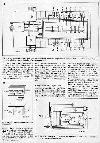
chip could be even cheaper if thesuperfluous gates were totally dispensedwith. Secondly, EPLDs and PLAs withlarge numbers of gates are slower, sincethe internal capacities are greater andthe signal propogation speeds are slower.In some circumstances therefore it isnecessary to rely on several smallmodules.The new member of the EPLD familyfrom Intel, the 5CBIC (bus interfacecontroller), fills this gap perfectly. Asthe name implies, this chip offers ahighly integrated solution for all designswhich contain bus transfer lines orgenerate control signals. Even the driver,which in some cases still has to be pro-vided in a bus interfac, can more oftenthan not be dispensed with when the5CBIC is implemented. The maximumcurrent on the M. side can be 32 mA.The 5CBIC thus offers all the advan-tages of high integration such as lowspace requirement, low current require-ment, low system and manufacturingcosts, and so on.Figure 1 shows the basic 5CBIC design.The 8 -bit wide A port on the busmanagement unit, BMU, lies directly onthe processor or controller bus. On the
"user side" there are two further 8 -bitports, B and C. As will be seen later,these three buses are bidirectional andcan be combined randomly, mendynamically, with each other. The sec-ond largest block is the programmablelogic unit, PLU, Which contains an 8
dedicatedEPLD unit. The PLU has 8
dedicated inputs and 8 bidirectionalpins. Both blocky can be supported viathe control unit.
Bus Management UnitThe bus management unit links ports A,B and C together and controls andmonitors the data flow over their lines.At the same time, the user can choosewhether the data flowing into these portsis to be latched or not. For this a latchenable signal can be generated M thePLU or supplied directly via a pin.Various EPROM cells, or dynamicallymodifiable signals generated by thePLU, control the data flow. Each portcan also be connected with any other.Depending on the requirements or thesubsequent hardware, the signal can begiven out on one of the outputs invertedor directly. Three signals generated in the'
mem. my Isse5.25
ogimmen611
H000000
NOEMST.on,ILItndarze,n,t,elinneixti2:;00),aporod,,am5mC.0.1:tetrz. compatible programmable logic unit 0.1E1 conventionally connected and
PLU can be sent by the output buffer tothe ports in the high resistance state, inorder that data may then be receivedthere. A multiplexer can make the signalsfrom a port, latched or not, available tothe FLU AND/OR array. The connec-tions between the three ports on theBMU itself, are programmed viaEPROM cells (Figure 2).
Fig. 2. The data flow on also be configureddynamically.
Consider the connection of the 5CBICto, for example, an Intel controller in theMCS 51 family. Then, using the BMU, itis possible to demultiplex the addressand date bus and make the rest of thecircuit available separately on ports B5.26 cm India may ISM
and C. The driver current of 32 mA perpin should be sufficient for most appli-cations. The working frequency of theexternal logic can be up to 12.5 MHz.Internally, the 5CBIC can work with upto 20 MHz. The PLU can now "ob-serve" the data or address flow andchipselects, generate other controlsignals or simulate an additional parallelport.
Programmable Logic UnitThe second large block on the 5CBIChip is the programmable logic unit,
PLU. This essentially has a 50060 EPLDuperset. Eight macrocells can, with the
help of EPROM cells, be adapted to the
application (Figure 3). Eight dedicatedinput pins and 8 bidirectional pins canbe connected to the macrocells. Con-sidering that data from ports A, B or Can also be obtained via the internal
feedback bus, the user has up to 24 in-puts, and up to 8 outputs available perproduct term.As has already been seen with theEPLD5 and PLAs logic operations, se-quenea are firstly converted into anAND/OR structure, which is usuallygenerated and optimized by the develop-ment system, IPLDSII (Wel Program-mable Logic Development System, ver-sion 2). This structure can then be veryeasily implemented in the AND/OR ar-ray on the input of a macrocell as a so -
Fig. 3. The 5CBIC mrerocells -1/O latches and high driver currents - make the use of illprocessor bus an optimal application.

Fig. 4. The IPLDSII allows the use of TTL,
called sum of products. Each macrocellalways has available the 8 dedicated in-put signals, the 8 macrocell feedbackloops, the 8 signals on the bidirectionalpins, and the signals on one of the BMUports. Since all signals are dealt withdirectly and inverted on the AND/ORarray, any combination can be pro-grammed by setting the correspondingEPROM cells. As opposed to the 5C060,each input signal can be individuallylatched. The only exception are the 8 bitswhich come from the BMU. These mayonly be latched together, or not at all.The latch enable signal for each inputlatch can either be generated individu-ally with the help of a product term orby a common control signal.Behind the OR gate, which can compriseeight product terms, there is an inverterwhose optimum algorithm (EspressoMinimizer) makes life a little easier,since it allows DeMorgan's theorem tobe reproduced in the hardware. Theconsequent I/O section of the macrocellis therefore very like that of the 5C060(Figure 3). Combinatorial or registerlogics can be created here. With registerlogics there is a choice of four registers.Depending on what is most suitable forthe application, either a D-, toggle-, MC -or RS-flipflop is used. Whereas whenusing a D- or toggle-flipflop all eightproduct terms are connected to one in-put, with the RS- and JK-flipflops theproduct terms are shared arbitrarily be-tween both inputs. Each register in theI/O part of a macrocell has a set and aclear input which are controlled via oneof its own macrocells.The clock signal, the latch -enable andthe output -enable signals can be in-dividually selected for control betweeneither the control bus (synchronous) or aproduct term (asynchronous). This also
gate array, and user.defined symbol libraries.
gives greater flexibility in comparisonwith the macrocells of, for example, the5C060.The output of a macrocell can be fedback into the AND/OR array via eitherthe control- or feedback bus. This signalis picked off before the tristate buffer inthe cell's output. Behind the buffer, andthus physically linked with the I/O pin,there is a second pick -off. If, therefore,the variable generated by the macrocell isonly needed internally, it can be furtherused as input if the buffer has to beswitched to high resistance. Using thisdual feedback option, it is very simple togenerate the so -caged buried registers.The development system keeps thesefunctions, transparent for the user.
IPLDSII: expansion of thedevelopment system supportsthe 5CBICOn many points, the developmentsystems of the EPLDs have been im-proved with the IPLDSII (Intel Pro-grammable Logic Development System,Version II - Figure 4). The new hard-ware is now based on the Intel Program-mer IUP-PC. Apart from EPLDs, allother EPROM -based modules, EPROMmicrocontrollers, etc. can also be pro-grammed.Mom important though for daily work-ing with EPLDs are the changes in thesoftware. So a new algorithm for op-timization (Espresso Minimizer) was im-plemented. For large EPLDs in par-ticular, important improvements weremade in the design density. The fitter,and thus the program part, whichassigns a design for optimization of themacrocells in the selected EPLD, hasalso been improved.Working with the IPLDSII has also beensimplified considerably and made morecomfortable. Although previously it waspossible to use modular design methodsand link together several source files,now it is possible to go even further backto the design macros. The macro -librarycomprises three blocks:
TTL macro -library Intel Gate Array Library User -defined library
The TTL library comprises a collectionof the most -used modules in the 74series. The user enters the modules withthe corresponding connections to the re-mainder of the logic. The macro -expander then converts this informationinto EPLD primitives which are reunited
5
P LeP
""
`LI
1
0
I--ort Inp Is to C aFe regsX-Li
880070-14
Fig. 5. With the aid of the IPLDSII, the 5CBIC bus management unit can be configured veryeasily.
tww, itehrsst wee 5.27

in them inimizer. The expander alsorecognizes if a chip is not being fullyutilized and erases the remaining gates.So, for example, if with the 7400 only 2of the 4 gates am used, only 2 will be im-plemented in the EPLD.Sometimes it is possible to use EPLDs asprototypes or backups for a gate armydesign. In order to make this as simple aspossible, Intel has grouped the gate -array macros in a further library, whichcan be implemented in an EPLD.Of great interest, of course, is the possi-bility, with the help of a few utilities, forthe user to create a library himself, theelements of which can also be made upof those of the other two, i.e., the TTLlibrary.As with the old version of the IPLDS,for documentation an advanced designfile (bletlist File), a logic equation filewith the actually implemented and op-timized functions, and a report file withthe utilization and pin assignment of theEPLD is generated. If during compilingerrors are found, the messages are "col-lected" in an error file.In the software output, a JEDEC-compatible tile is generated which servesas input variable for one of the program-ming units, from Intel or mother, whichsupport the EPLDs.The basic version of the IPLDSII sup-ports the circuit input with the help ofan editor. It is however simpler to use thelogic builder which Mows interactivegraphically -supported conversion of acircuit diagram into a netlist. The logicbuilder also makes configuring theSCBIC bus management unit verysimple. A BMU block diagram comes upon the screen (Figure 5). Using the cur-sor, it is possible to "go into" the desiredblock, is the block for port C. Bysimply pressing the "RETURN" key, itis now possible to select from all the con-figuration possibilities. The respectivefunctionality a entered on the circuitdiagram on the screen as are the connec-tions to the other ports. Later the outputenable (0ex), latch enable (Ion) or select(Selz) signals am connected. The signalscan be connected directly to pins or con-trolled from one of the macrocells. Thecompiler takes care of the allocation.In order to simplify input, memoirs soft-ware packages expand the IPLDSII.ISTATE for example allows input ofstate diagrams and truth tables. Furtherlibrary and conversion packages allowcircuit diagram input using PCAD orDASH.
Since the middle of 1987, Intel has alsobeen offering an IPLDS-compatiblesoftware package for circuit diagram in-put, which is reasonably priced.SCHEMA II, as the package is called, isproduced by OMATION and sold by,amongst others, Intel. In addition totheir own schematic capture software,some libraries contain EPLD primitivesand 74xxx symbols, which can be sup -
5.28 slim, mi.., ma
6. Thn 5CBICs w a lb -bit, twin.processor system carry out the control of the dual -panedRAM.
ported by the IPLDSII. The circuitdiagram can now be input and advan-tage taken of the SCHEMA software, i.e.by plotting on simple EPSON printers orHP LASERJET, and even on plottersworking with larger than A4 format.The circuit, which may, of course, con.min TTL symbols, is converted into anadvanced design file, which then servesas input to the IPLDS compiler. Thedesign is minimized and then filled into
the EPLD selected. In addition to theplot files, the some output files aregenerated for documentation as whenthe logic builder is used. In additionSCHEMA II offers a range of otheraids. Thus, it is possible for the user toautomatically create parts lists, carry outa design rule check, check routing, andprint out various data formats, pinlists,netlists, and so on.
Fig. 7. Photograph of the experimental set-up of Fig. I.

16 Bit dual port memoryA popular way of making computersfaster is to have several processors work-ing in parallel on a single task. Here, theprocessors must from time to time ex-change data for synchronization andmanagement from shared memories.This exchange takes place more oftenthan not via a dual -ported RAM. The
logic, which is necessary for managingsuch a RAM, can now wry easily becreated with the help of two EPLD5 ofthe 5CBIC type (Figure 6). Here, two16 -bit processors am accepted which canaccess a joint memory bank. Each5CBIC can work with an 8 -bit width.Two are therefore required. The firstmodule manages the upper 8 bits of the
databus. It also takes care of arbitration.The second manages the lower 8 bits. Inthe FLU, a 8 -bit counter is implementedwhich is required in other parts of theapplication. Further information isavailable from Intel in the form of appli-cations leaflets.Eckart Baum is with Intel, Munich.
TEST & MEASURING EQUIPMENT
Part 1: dual -trace oscilloscopes (E)
The final article in Julian Nolan's review of dual trace oscilloscopesdeals with the Hung Chang 01-635.
The Korean company of Hung Chang is,perhaps, better known for its range ofDMMs, frequency sources, andcouMers, some of which am said undera variety of retail trade names.The Hung Chang 0S-635 is a 35 MHzdelayed sweep oscilloscope with a 6 kVCRT retailing at £399 (excl. VAT), whichis only about £80 mom than one wouldexpect to pay for a 'basic' 20 MHzmodel.The delayed sweep is of the 'coarse' var-iety; the instrument is also fitted withtrigger hold -off and single sweep modes.The 0S-635 is fitted with a standard IECmai socket. The line voltage is exter-nallyns adjustable to 100, 120, 220, or240 VAC.The instrument is not fitted with a swivelstand, but the single position stand pro-vided instead allows easy stacking of theunit.The 0S-635 is of average depth andwidth: 352 mm and 294 mm respect-ively, but its height of 162 mm is perhapsrather more than might be expected.
Two high -quality probes (1.4 ns rise timewhen in 10:1 attenuation mode) are sup-plied as arc accessories for use withthem, including a BNC adaptor andspring -loaded clip.
Front panel. The front panel is probablyone of the OS -635'e most distinguishingfeatures, with colour -coded sectionssuchas triggering and IL -amplifier func-tions. Although the colour coding addsto the case of operation, the panel is not,
as common, anodis but the markingshave been printed on. This, togetherwith the exposed potentiometer bushesof some controls, gives the instrument arather rough and ready appearance.However, this certainly does not meanthat it is of low 'quality.
Y -amplifiers. The attenuation coef-ficient of both Y -amplifiers is variableover a range of 10 V/div to 5 mV/div. Inaddition to this, a x5 magnification fa-cility is also available, enabling maxi-mum sensitivities of I mV/div to beachieved.Undoubtedly, one of the main featuresof the OS -635 is its 35 MHz bandwidth.
wave a
This is maintained down to 5 mV(-3 dB). The I rnV/iliv sensitivity bringswith it the restriction of a 10 MHz band-width (rise time 35 ns).Both Y -amplifiers have aircontinuouslyvariable attenuation control, which in-creases the maximum attenuation coef-ficient to 30 V/div. Only one channel canbe inverted.The performance of the Y -amplifiers isreasonable in of frequencyresponse and bandwidth, given theirrelatively high frequency range. But,despite these mediocre characteristics,they arc still undoubtedly better than theaverage 20 MHz Y -amplifier at this price
elektp, intlia may wee 5.29

Table /7.
ELECTRICAL CHARACTERISTICSIlne voltage: - 100. 120, 220, 260 VAC
10%, externally adjustable. Powerconsumption: 30 Watts
Line frequency: 50-50 Hz
MECHANICAL CONSTRUCTIONDimensions: - W 256 mm, H 162 vim,D 352 mm
Homing steel sheetWeight: approx. 2.5 kg
Y AMPLIFIER ETC.Operating modes: -CHI alone, CH2 alone.Inversion capability on CH2 only.Any combination of CH1, CH2 (alternateor Mopped 1250 kHe)
CH1 + CH2Frequency response 0...35 MHz1-3 am.
Risetime < 10 nsec,136 nee v 5 Mag.,Deflection factor 10 steps:5 mV/div...5 V/div x 3%.
x 5 inagoiRer extends range to 1 mV/div,MHz batiiwidth..
Input coupling: AC, DC or Gnd.Input impedance: 1 M9/25 pF, real inputvoltage 300 CDC + peak ACI
X, MODECHI 0 -axis and CH2 V-exia. Leas than 3°phase shift at 50 kHz
Bandwidth 00 to 1 M. 1-3 del.
SWEEPOperating modes - normal: tienbase Adisplayed Ina delay), intensified:timebase A intemIlled by trig delay overmagnification area; delayed: A sweepstarts after delay time.
A sweep time 100 ns/div to 0.5 s/divX 3% in21 ranges; 1-2.5 sequence;vernM
co.ol slows sweep down by ento 2.5:1.Delay time - 10 ms to 1 As in 5 steps,1:1 sequence: variable control for OneadjoMment.
Sweep magnification - x6 x to% tomierror.
Hold off - variable up to 10:1.Delay modes - continuous delay.Delay fitter - 1/5000.Single sweep .601.
TRIGGERsTrigger-auto and normal.
Trigger coupling - AC; DC: HF reject: LFreject: TV frame ans line lautol.
Trigger murces - Ch; CU: alternate:line: end ext/10.
Triggering sensitivity - Internal: 1 div at35 MHz, external: 0.2 Vap et 35 MHz.
MISCELLANEOUSCRT - measudng area 80x 100 ow;accelerating voltage 6 kV; metal backed;PDA.
Compensation sigml Mr divider probe -amplitude approx. 0.5 Vq1 .3%; Ire.QUOnCV 1 kHz.
Z modulation sensitivity - 3 V (completeblanking,
Warranty - 1 Wer.
Despite being specified at 3%, overshootis particularly evident on some ranges,although it remains within the quotedlimit.The dynamic range is somewhat limitedat about 41/2 divisions at 35 MHz, butshould, none the less, be acceptable formost purposes.A minor point is that the x5 magnifierhas the effect of magnifying the traceoffset, which is set by the Y positioncontrol, with the result that some repo-sitioning of the tram is required whenthe x5 magnifier is actuated.Since the x5 switches are incorporatedin the Y position controls, it happensthat when these controls are accidentallyturned when they are pulled out In actu-ate the x5 magnifier, the trace shifts. Ifthis has already been centred, an un-necessary adjustment is required to re -centre it.Chopped (200 kHz) or alternate sweep isselected automatically by the time basespeed selling.
Triggering. Triggering on the 0S-635 iscomprehensive, including LF and HFfiltering, alternate channel sourcing andTV synchronization. In addition to this,unusually fora scope in this price range,an external +10 facility is also provided.The auto/normal and triggeringthreshold controls are combined intoone in a similar manner to the x5 at-tenuation coefficient magnifier. Here,the problems brought about by this arenot so acute, but still noticeable; theauto position is selected with the levelcontrol fully out. All other triggeringcontrols (of the slider type) are, however,relatively easy to operate.TV triggering is particularly notable, be-ing selectable from positive or negativesynchronization and, with the inclusionof automatic line and frame switching,incorporated into the timebase coef-ficient selector. Triggering sensitivity isalso good: typically 0.2 div to 10 MHz,increasing to 1 div at 35 MHz and 3 divat 60 MHz, which is the maximumreliable trigger frequency. External trig-ger aenetivity is also good at 100 mV to10 MHz and 0.2 V to 35 MHz. This can,however, be increased by means of the+10 control to eliminate false triggering,
used, for example, by noise. An alter-nate channel, or composite mode, is alsoincorporateWor observation of twounrelated On rims of frequency) signalsources. Triggering symmetry (rising orfalling slope) proved to be out by ap-proximately 1 division over a total ver-tical deflection of 8 divisions. The HFand LF facilities provided are effective inobtaining a stable trace even in cases ofwaveforms with a very high modulationcontent, and are a further useful ad-dition to the 0S -635's trigger functions.Both trigger and 'ready' LEDs are alsoincorporated, lighting when the mope is
stably triggered or reset respectively.Trigger holdoff is also a feature of theOS -635, which makes the triggeringfacilities provided by this scope amongstthe best in its class.
Timebase. The 00.635 is equipped witha single timebase and an uncalibratedvernier delay lime control. This has theconsequence that in the vast majority ofsituations only uncalibrated delayedsweep measuremems can be made ofwaveforms which exceed the maximumhorizon.] deflection limit of 10 div-isions. In most cases this limitation doesnot affect the measurement of waveformrise times.The main timebase itself ranges from arespectable 0.5 s/div to 100 ns/div,although, obviously to limit the cost ofthe deflection circuitry, only a x5horizontal magnification system hasbeen incorporated, increasing the maxi -
um deflection speed Be 20 ns/div. Thetrigger delay time coefficient can beselected from one of 5 (the front panel ismarked for 6) covering the range from1 sec to 100 msec in a 1.1 sequence. Thisdeparture from the standard 1-2-5 se-quence is false economy since, althoughit reduces the number of switch positionsto 5 instead of IS, highly acculate ad-justment of the vernier control is re-quired at higher magnification levels. Italso has the effect of reducing the easeof use of the delayed sweep facilitysignificantly in my opinion, largely dueto the accurate vrnier adjustmentswhich have to bee made. Rise timemeasurements would have been greatlyhelped by the provision of a triggereddelay facility in addition to the normalcontinuous mode, as well as a delay line.Looking at the situation in perspectivehowever these facilities can hardly be ex-pected for £399, but effective operationof the delayed sweep facility withoutthem may in many applications prove ex-tremely difficult. The delayed sweep dis-play modes of normal, intensified ordelayed should be adequate for mostpurpose.Timebase accuracy is inside the specified*3% (and the rather high ±10% whenusing the x5 magnifier). Linearity isalso within the quoted *3% over mostof the range although it is noticeable atthe start of the trace over the first 11/2small divisions on the maximumtimebase speed that the deflectioncharacteristics were, to say the least,non-linear.
CRT. The 6 kV tube enable both goodintensity and brightness to be main-tained over the whole range of sweepspeeds. The CRT itself is of the metalbacked PDA variety and gives a goodperformance, especially in terms offocusing, which is certainly of a highstandard. The tube is slightly curvedacross its face, howevel, and while this is
5.30 ttnisv .vss v.( wet

not to a great degree, and should not af-fect measurements, it is still worthnoting. Tabs geometry is reasonable,with some barrelling and pincushioningpresent. The tube's good performance ishindered by the lack of an automaticfocusing circuit, with the consequencethat any major alterations in tubebrightness can cause considerabledefocusing of the trace, making someform of focus adjustment essential foraccurate measurements.
Construction. Construction of the OS -635 is poor. While mostly not of lowquality, the OS -635 is in places poorlyfinished, with a number of sharp edgesevident on the enclosure both internallyand externally. Internally, masking tapeand small pieces of dowelling are used toseparate some of the wire interconnec-tions, which, while perhaps not impair-ing the reliability of the instrument, arereally unacceptable in a modern instru-
ent.External construction is based on a steelchassis, with two sheet steel panelsenclosing the top, sides and underneathof the scope. These appear to have hadlittle done to them in terms of machiningsince being originally pressed and foldedsince they still contain one or two sharpedges. The front panel surround is con-structed from four separate pieces ofaluminium with the consequence thatthey are joindedInternal construction is of a higher stan-dard, with the high voltage and EHTsupplies enclosed, and the Yamplifierspartially screened. The scope is basedaround four PCBs, connections fromwhich are all made by connectors tforeasier servicing and while this leads to alarge number of interconnections, it
should not affect reliability. As well asbeing used to separate some of the inter-connections, masking tape is also usedaround the CRT.Overall construction both internally andexternally appeared to be average in itsclass, and whether this will effect the re-liability remains to be seen. The qualityof components used is generally goodand this may be worth taking into ac-count.
Manual. The 30 page manual includes afull circuit and PCB layout diagrams. Afull circuit description and initial set upinformation is also given, along withcalibration and preventative mainten-ance sections.
Conclusion. Looking at the specificationalone, the OS -635 appears to represent aextremely good price/performance ratio,with a 35 MHz (-3 dB) bandwidth,6 kV PDA tube and delayed sweep fa-cility. In reality, some of these facilitiesare limited in their performance, whichis especially true of the delayed sweep fa-cility, which in some situations offerslittle more than can be achieved with ascope that possesses a good trigger per-formance. Having said this, both thetriggering performance and facilities of-fered by the 00.635 are good for a scopein its class and should not be ignored.An automatic focusing circuit is not fit-ted, which is unfortunate since the 6 kVPDA is capable of producing a trace ofboth excellent intensity and sharpness,but to maintain this without the pro-vision of an automatic focusing circuitrequires an adjustment in the focusingpotential for a significant change intrace intensity. Both the internal and ex-ternal construction have the appearanceof a preproduction prototype rather than
a production model, but despite thisthere is not apparent reason why the OS -635 should not be reasonably rugged ina variety of environments. To sum up,for its specification the Hung Changrepresents a very good price/perform-
ratio, its particular strengths lyingin its 6 kV CRT and 35 MHz bandwidth.The OS -635 may well be worth consider-ing for a large number of applicationswhere a bandwidth of 35 MHz and highbrightness tube are required on a limitedbudget, or as a cost effective alternativeto a 20 MHz scope.
The Hung Chang OS -635 was suppliedby Black Star Ltd. 4 Harding Way St. Ives HUNTINGDON PE17 4W12 Telephone (0480) 62440
Other oscilloscopes available in, theHung Chang range.0S-61.55 - dual trace 15 MHz portable;rechargeable battery operated; weight4.5 kg; sensitivity 2 mV; maximumdeflection speed 100 ns/div; 1.5 kV CRT;up to 2 hours operation from fullycharged batteries; £399 excl. VAT.
OS -620 - dual trace 20 MHz; setivity 5 mV; maximum deflection speed40 ns/div; 2 kV CRT; component tester;power consumption 19 W; £295 excl.VAT.
09-650 - dual trace 50 MHz; utivity 1 mV; maximum deflection speed40 ns/div; 17 kV CRT; delayed sweep100 ms to I us; £579 excl. VAT.
Table 18.
CATEGORY Unaacis-factory
Satis-factory Good
VeryGood Excellent
TRIGGER FACILITIESTRIGGER PERFORMANCEDEL'D SWEEP FACILITIESDEL'D SWEEP PERFORMANCECRT BRIGHTNESSCRT FOCUSINGY AMP ATTENUATION RANGEINTERNAL CONSTRUCTIONEXTERNAL CONSTRUCTIONOVERALL SPECIFICATIONOVERALL PERFORMANCEEASE OF USEMANUAL
Bea 5.31

STEREO SOUND GENERATOR
A high -quality stereo sound effects board for the Universal I/O bus,based on Volvo's Type SAA1099 advanced single -chip complexwaveform generator. Applications include enlivening computergames and operation as a programmable test generator for
simulation of composite AF waveforms.
Here is yet another simple to build exten-sion board for the Elektor India Univer-sal I/O bus ut. It answers the populardemand for an advanced sound gener-ator that can be programmed to producean astoundingly wide variety of complexsounds in stereo, simply by having thecomputer send the appropriate com-mands and datawords for each channelvia the Universal I/O bus. The mainspecifications of the sound generatorboard described here are shown in theshaded box below.
Digital soundThe block diagram of the Type SAAI099programmable sound generator chipfrom Valve (Philips/Mullard) is shownin Fig. I. The interfacing logic is shownto the left and at the top of the drawing.To the computer, the chip appears as aWOM (write only memory). Reading ofthe chip Status is, however, possible if theprocessor writes copies of the com-mands and data into a RAM table forretrieval at a later stage. Input line AO ofthe sound generator chip is made highfor loading register address bytes, andlogic low for databytes. The interfacelogic on board the SAAI099 latches theregister address, obviating the need torepeat this when writing new data to thelast selected register. The process ofsound generation in the SAAI099 iscompletely digital, and based on pulse -width modulation.Table I gives an overview of the functionassigned to each bit in a particularregister. The required octave is pro -
STEREO SOUND GENERATORBOARD
Features:
six frequency Bono...2048 tones in 8 octaves
two noise generators six tone/noise mixers six stereo amplitude controllersII two stereo envelope generators stereo six -channel output mixer on -board 2x200 mW AF ampli-
fies
grammed separately for each Mee gener-ator by writing a 3 -bit number inregisters 10a, Ile and 12s. The fre-quency range covered within each octaveis given in Table 2. The frequency pro-duced, fn is determined by the contentsof registers nu incl., and can becalculated from
8810.[Ha]
(consult 'Bible 2 for 0. and F.).The contents of registers 14a and Hudetermine which signals are passed bythe six on -chip miners. There are fourpossibilities: (I) all signals are blocked;(2) only the lone is passed; (3) only noiseis passed; (4) both the tone and noise arepassed. The noise generator clockrate-hence the no colour-is in-dividually programmable on the left andright channel by writing the appropriatedata to register 16u.
Sin amplitude controllers ran be pro-grammed to set the volume of thegenerated sound on the stereo outputchannels. This is effected by writing datato registers 001....05n incl. (left: LSnibble; right: MS nibble).The last programmable section to be dis-cussed is the envelope generator, whoseoperation is best explained with refer-ence to table 2 and Fig. 2. In the draw-ing:(I) indicates that the output amplitude is
determined only by the amplitudecontroller when the envelope generator isdisabled:(2) indicates that the maximum ampli-
tude is 15/16th of the value set by theamplitude controller when the envelopegenerator has been enabled;(3) indicates the moment when a new
envelope waveform can be started byreloading ES and/or El.
=---
roe -"="Ell CI E21!
-
maiMS
ilb I=3=0r
im1q
'MNI IIlitl..:=_ IE211
1E3=
IFCI I=Ira=I 1:2 EMI EMI
Fig I Ialemial Mrarrare of Me Type SAAI099 promammable sound palmier.

Table 1. 2
INTERNAL REOLSTER MAP'
regiMer dataacicirea D3 [ 02 l 01 10o
00
07106)05100ARO ALO
01 API ALI
02 AR2 AL2
03 AR3 AL3
ARC AL4
05 AR5 AL5
36 00
mm
OS FO
09
OA F2
OB F3
00 FO
OD
00
OF 00
01 00
03 02
05 04
00
0 FE5 FE4 FE2 FE1 9E0
NES NE4 NE3 NE2 NEI NE0
00
E3
IA 00
00
IC 01011 . 1 1 . 1 SE
00
00
00
Amen°.
Frequency 0
Frequency I
Frequency 2
Frequency 3
FrequeneY
Frequency 5
Octave I: Octave 0
Octave 3: Octave 2
Octave 5, Ocmve 4
frequency Enable
Noise Enable
Noise garreratr INo. generatoor 0:
Envelope generator 0
Envelope generator I
Sound Enable
The lotto sin brackets to the right of the of the envelope is determined by fre-envelope waveforms in Fig. 2 refer to the quency generator 1 (or 4),"or by the com-bit combinations M Table 2 (E0 -El; bit I, puter repeatedly writing to the address2, 3). latch, clocking the envelope_gneratorWhen the envelope mode is selected for with the WRITE signal (WS). Thea channel, the amplitude of the associ- period of the envelop, tr is calculatedaced amplitude -controller is rounded fromdown to the nearest even value (the LSbit is considered low). If, for example, (,=8/frire,the volume was set to value 1, it isrounded down to O. An envelope gener- in the 4 -bit mode, orator can also function as a tone gener-ator. If the controlled frequency channel ,=4/fatis inactive (tone & noise generatorturned off), the programmed envelope in the 3 -bit modewavevorm will appear at the output. Inthixway, the sound generator board can Bit SE (sound enable) can be used forfunction as a programmable waveform turning the sound generator on and off.generator with a maximum output fre- The programming of sounds is largely aquency of about I kHz. Faster envelope matter of trial and error establishing ofwaveforms can be achieved by reducing the required bit patterns, writing data tothe resolution of the envelope from 4 to the chip, listening to the resultant sound,3 bits (bit 5 of byte E0 or El). The speed debugging the data and register selec-
°
,// , ,
, ,A
74,.s. Programmable envelope waveform
bons, and making the requiredmodifications.
Circuit description andconstructionThe sound generator board is composedof relatively few parts-see the circuitdiagram of Fig. 3. The WR signal forthe SAA1099 is made by combiningR/W and 02 in gates Ni and No. Thecrystal -controlled oscillator built aroundT. and To provides the 8 MHz clocksignal for the sound generator chip.The pulse -width modulated outputsignals of the SAA1099 are converted toanalogue in R -C filters composed ofR9... Er incl. and Co...Co incl. Inte-grated stereo output power amplifierIC, can provide about 2 x 200 mW tothe loudspeakers.Construction of the board is straight-forward, and requires no further detail-ing. Supply power for the sound gener-ator board may be obtained from thecomputer. Due attention should be paidto adequate decoupling, however: insome cases, interference on the supplylines from the computer will necessitatefeeding the board from a separate,regulated, 5 V supply (cut off pins I and2 at the board side of edge connectorKi).
Control softwareControl programs for the sound gener-ator board should be written with easeof register operations in mind. A simple,yet effective, way of achieving access tothe registers and their contents is to
slam, India may hem 5.33

Fig. 3. Circuit nagram of the stereo sound generator board.
5startREM Mitialization
=,7nLPOKE addres-larah, N
POKE datatat, 0
registerlall I= 0
REM initialization completePENI start experimenting
clear screenREM printFOR N o0 TO
NEXT N
INPUT "eddres,,res
registerlaesirest : =dataPOKE addres-leteM1, addresPOKE data -latch, deta
go to toot,
'ig 5. Suggested structure of a controlpro ram for dm sound
ofboard. Completed prototype of the stereo sound effects generator for the Universal I/0 bus.
make use of a register selectionsubroutine in conjunction with datastatements and arrays. Also, do notforget to copy data written to theregisters in reserved memory areas of thecomputer.The program structure shown in Fig. 5 isintended as a' guide for writing one'sown control programs for the sound gen-erator board. The program starts bydimensioning army variable "register".
This army is set up to enable the com-puter to keep track of the data written tothe registers in the interface. Next, allregisters in the SAAI099, and array"register", am reset to nought in a FOR -NEXT loop. The program then enters ainfinite loop for fetching register selec-tion codes and data from the keyboard,and transferring these to the SAAI099via the Universal I/O bus. First, theregister contents are displayed on screen,so that the status of all registers is knownat any time Consecutive INPUTstatements then prompt the user to enterthe register address, and associated data.The program then updates the contentsof army "register", and, of course, thatof the addressed register. It then returnsto the loop entry point.
Finally, here are two examples of soundsthat can be generated by the sound ef-fects board:Steam locomotive, set AR2 and AL2 toan arbitrary value greater than I. SetNE2=1; N0=0; E0=4. Bits and bytesnot mentioned are set to nought, except,of course, the sound enable bit.Bell: set the volume as required (AR2and AL2). Set F2=FFn, 02=7; FE1=1;FE2=1, E0=4 and SE=I. Bits and bytesnot mentioned am set to nought. St
Referss Universal I/O bus. Elektor India,
June 1985.
Fantasia on a MIDI theme. ElektorIndia, December 1985.

REGISTER DESCRIPTION
ARx, /Mx 0 Mrs for amplitude control of generator k, left and rightchannel.
Px 8 bits for frequency control of generator x in designatedoctave.
Ox 3 Mts for octave c.orcl of generator x.000 lowest octave 30... GO Hs001 50-122 Hz010 122...2.Hz011 204...088 Hz100 099 ...977 Hz01 978...1950 Hz10 1.95...3.90 kHzIII highest octave 3.91...7.81 kHz
FR( I hit FEk = 0 inclieetes that generator x is off.FE2 = 1 Indicates that generator x is on.
NEx I bit NEk - Indicates that mixer oes not add noise.NEk = 1 Indicates that mixer x adds noise.
NI, N2 2 bits for noise generator ontrol. These bits .1 the clockrate of the nol. generator.
00 31.3 kHz01 15.6 kHz0 7.6 kHz
11 51 Hz . 15.8 kHz (frequency generator 0/31
E0, Et for envelope .ntrol.ft 0 = left and right component have the samee0
envelope.= right component has inverse envelope of that
applied to lett component.hit 1.2.3 000 zero amplitude la/
001 maximum ernplitude.1121010 eingle decay lc,011 repetitive decay Id/ waveforms are100e1ngle ar lel illustrated in Fig. 2.101 repetitive decay 111110 single attack MI111 repetitive attack 111/
bit 4 '0 . 4 him for envelope control Ilme,,,,- 977 HO.I v 3 bits for envelope control Mc.- 1.95 kHz,.
hit 5 0 . internal envelope clock (frequency generator 1or 01.
1 - external envelope clock fetidness write puts.bit 6 must he O.I. 7 0 = reset Inc envelope cont.,
1 - envelope control enabled.
SE 0 = all channels dNahled.1 =all channels enabled.
Resistors. 5961:
01.10KRe...Rs =NWRedI1Rio=071(Re.1131(
Capacitors.
iCNCNCko =1001CNCB=10nCacCiorCii =100p; 6 VCRCS:Cm-1n0Cl2;C14=0700; 6 VCM:Cis-15OnCINC1.070pCts.311,
Semiconductors:
TirT2-1#0.94 ICricklewood BenronicelICi SAAIOSS ICSI Elecbonics1IC2=U20320 (AEC-Telefunk.: Cir./1C2=70HC100
Miscellaneous:
Xi= qua. crystal 8 MHz.Xi . 21 -way righbangled plug to DIN41817.
(stock no. 071.018: Plectromail 05302045151.
LSIRS2- miniature loudspeaker: 84;250 roW.
PCS Type 81142
tintoort
PCBs& Set of COMPONENTS
for projects are normally available with
precious® EamaH COPOtembOu
92-C P10110, Rood...nay-400 007 Phones: 3.37469/369478
///
nomGO 11 YcY
itjt NIFig. 4. Printed circuit board for building the stereo sound generator
elekter nu, ma 5.35

Before proceeding with a discussion ofthe parametric equaliser it is perhapsa good idea to discuss why it is superiorto the,more comrnon 'graphic' equaliser.A 'graphic' equaliser such as the ElektorEqualiser consists of a number of bandselective filters with fixed centre fro.
quencies spaced at equal inter,ilkvals on a logarithmic frequencyscale, usually at octave inter -
ON
vans, though more expensiveunits may boast thir-octaveliners. Each of these filters
egoe moped with a
Cyan111 so that it can14/4441. apply boost or cut to the
band of frequencies overwhich it is active. The
11011L term 'graphic' arosefrom the common
ef, ai0611-4,',is' lir,: ,::, : 4; 1 Al
AI b.'
4;1111;ii,7NOilal /TiI,
A combination of statevariable filters and ahighly specialised Baxandalltone control network is USeCIin the 'parametric' equaliserdescribed in this article, whichoffers considerable advantagesover the more common 'graphic'equaliser. Use of a parametricequaliser allows the frequencyresponse of a domestic hi-fisetup to be tailored to a degreepreviously only attainable inrecording studios. Such is theversatility of a parametricequaliser that even sceptics whoturn up their noses at audioequalisers may be forced to revisetheir opinions.
Figure 2 shows how the characteristicsof a parametric filter section may bevaried. Figura 2a shows variation of thegain, figure 2b shows adjustment of thebandwidth, while figure 2c showsadjustment of the centre frequency.Figure 3 illustrates the adjustmentspossible with the parametric tonecontrols. Figure 3a shows how variableboost and cut may be applied to thewarernes of the audio spectrum, aswith normal tone controls, whilefigure 3b illustrates Me unique featureof the parametric tone controls, namelythe adjustable turnover frequencies ofthe bass and treble controls.Having briefly discussed the differencesbetvveen parametric and graphic equal-isers, the advantages of a parametricequaliser can now be illustrated. In anutshell, the purpose of an equaliseris to make the frequency response ofan audio reproduction chain flat byproviding gain where there are dips inthe response and attenuation wheysthere are peaks. Figure 4a shows theresponse of a typical reproductionchain, as might be measured using anaudio analyser. This hes a number ofobvious deficiencies. The 'grass. on thetrace is due to a large number of sharpnigh QI resonances, which can be as
gelse of much as 20 dB deep. Fortunately these
slider poten- peaks and troughs are inaudible due top.p.., in so, their wry sharpness, since they each
equalisers whose occupy a bandwidth of only a few Hz.
snider position is no.osly supposed by
orne to represent therequency response of the
system. However, the termgraphic' will be used to dis.
inguish between this type ofqualiser and the parametric
equaliser,The only variables in a graphicequaliser are the gains of theidividual filter sections, since
the centre frequency and Q(which determines the bandwidth)
of ach filter are fixed. A parametricequaliser has fewer filter sections than
raphic equaliser, but all the para.meters of the filter are adjustable, e.g. case they will be very difficult togai , bandwidth and centre frequency. eliminate) then the response curve canA block diagram of the Elektor pare be simplified to that of figure 4c, whichmeric equaliser is shown in figure I. shows only the principal deviationsThit consists basically of just three from a flat response. These we thepar metric filter sections - band deficiencies that must be removed byselective filters whose gain, centre fre- an equaliser.qtr ncy and 0 are all adjustable. De-fici ncies at the ends of the audio spec-trum are catered for by a parametric Parametric or graphic?Be andalktype tone control to provide It is fairly obvious that to removebas and treble adjustment. These peak or trough from the frequencyco trots operate in a similar manner response the correction applied mustto the parametric filter sections, but be the exact inverse of the deficiency,employ lowness and highness filters i.e. the boost or cut applied must berather than band selective filters. the same as Me depth of the trough
Th is perhaps just as well since itwouis Id be impossible to cancel out eachof these resonances.If this 'grass' is ignored then the responsebecomes something like that shown infigure lb, in which the major deviationsfrom a flat response are more readilypparent. It is evident that the response
falls off sharply below 50 Hz and above10 kHz, that a large peak exists atabout 750 Ha and a trough at about6 kHz.In addition there is a slight 'ripple' inthe response due to a number of peaksand houghs a few dB deep. If oneaccepts the tact that deviations of afew dB can be ignored land that in any
5.36 01.0r india may nee

1
Figure 1. Mock diagram of a parametric so aliser, which torowisas three filter sections with variable gain. bandwidth and centrefrequency, end toms controls... variable gain and tome. ftealUancv.
2
a T
Figure 2.191. InuStrat 99th, affect of wiryingt gain of a filter section.
ME11111111M1111 I ME1111111111111111MUNN IM111111/. 11111111M111111
manniummuumin= moo MEMIMIKVO I 'WM11111.11111111
=Ell I 1,1.1MEP 11111M111 I
Mini h. =7411 I UIIIIMINIM 11110,11//%611111N1111111MEIN /#62/11111111111111MEIN II 10110NMEIN II MEIN ,11//PAIIIIIIIMMIll I111111111 =E111 '2111111111MM111
1111M111111111111111111eltect of varying the 0 of e fleet section.
(,I.Thtf.tygth.92999,f99-of a Mar section.
T
b
7
5 .37

3
1I It
a IE11111 11011111M1111111.1111111111111111 1E1E11111
I11111111111111111111 01E1111 IIMMIllrdi 1111E11111ME11111 E1111 1111111ga 1E1E11111
122101111 IIii 1111E11111IMAM IINIARNISi 1E111111111
I PAMIRM MEMOMNIIIIII!Ki402111111110ittiglIUIIIII11111111111111651012111111MVIRK I! MINIMMINIM REF/1111 =MK 1111E11111111111111111111. MUNI =MOM 111111111111111111111111!IAM11I11111110111111111111
i! MINIMFiourel lab Showing me effect of serving 111111.111111MMIIIIIMENEU
the gain of the geom. tone centrists.
ry
b
110. Illustrating the effect of altering thetornover frequency of the bess end treble
or height of the peak, it must be appliedat exactly the right frequency. and the0 of the correction network must bethe same as that of the peak or trough.It is apparent that these criteria canhardly ever be fulfilled by a graphicequaliser. Firstly, it is unlikely that thecentre frequency of a peak or troughwould coincide with the centre fre.quency of one of the equaliser filters.Secondly, since a graphic equaliser hasfilters with a fixed 0 the shape of thefilter response cannot be tailored to fitthe curve of the peak or trough. In factthe only parameter that can be variedin a graphic equaliser is the degree ofboost or cut. With a parametric equal-ser on the other hand, the gain, centrefrequency and 0 of a filter section maybe varied so that it is almost an exact fitfor the peak or trough which it is toeliminate. At the extremes of thespectrum Baxandall tone controls withvariable gain and turnover frequencycan be used to compensate for the'droop' which occurs.Like the graphic equaliser, a parametricequaliser may have any number of
filter 'entrails. The filter SeCti0.15 arenecessarily rather more complex thanthose of a graphic equaliser, however,since each filter section is considerablymore versatile it is possible to achievesatisfactory results with fewer filtersections, so that the cost is comparablewith that of a graphic equaliser. Fornormal domestic use an equaliserconsisting of three parametric filtersections plus Baxendall tone controlsshould be quite adequate.
Parametric filter sectionThe block diagram of a parametricfilter section is given in figure 5. Theheart of the filter is a selective network,which will be described in detail later,whose centre frequency and bandwidth10) can be independently varied. Thegain of the filter can be varied by aganged potentiometer. Pl.The selective network is a state -variablefilter or two -integrator loop, whichreaders of the 'Formant' synthesiserarticles will recognise as being essentiallysimilar to the Formant VCF. However,
in this circuit the centre frequency ofthe filter is manually controlled byOwn -gang potentiometer Rio,. whosetwo sections vary the time constantsof the integrator stages. The 0 of thefilter, and hence the bandwidth, is
varied by altering the values of RQ.
Complete filter circuitFigure 7 shows the complete circuitof a parametric filter section. The state.variable filter around Al to A4 isimmediately recognisable, as is thevariable gain amplifier, ICI. The Qdetermining resistors and potentiometersRo become R6, R7 and P2, whilst thecentre frequency is set by P3. Thisarrangement differs somewhat front thatshown in figure 6.However, if Rip, were a potentiometerconnected as shown in figure 6 then itwould haw to have an inconvenientlylarge value if the desired tuning rangewere to be covered. The arrangementof figure 7 is electrically equivalent andallows the effective value of Rin, to be.
5.38 elekler may AM

4
INE111111111111111111111111111111INE111111111111111111111111111111M11111111111111111111111111111111111111111111111111111111111111111111111111111111111M11111111111111111111111111111p1111111111111/' IME11111111111111
111111.71,11' ''.11111'9111111111111,' U 1E111111
MEP ...MIMI. 111111111,11116...611111 11111111
I.111111111111111111, III 11111111 +11111111111111111111 IR 1111111 A11111111111 1111111111M 1111111
4111111111111 1111111111M 1111111 1111111111111111111111111M1111111
b
3o that the response can he simplified asshown here. The few dllt of ripple can also
be ignored, reducing the trace
a
Figure a. The frequency response of a 3VPiceireproduction chain, as it might be measuredusing an audio analyser. The 'grass' on thetrace can he ignored.
C
its umplest form. The remaining Peaks endtroughs in this simplified frequency response
h can be removed by using an aqua.,'tt
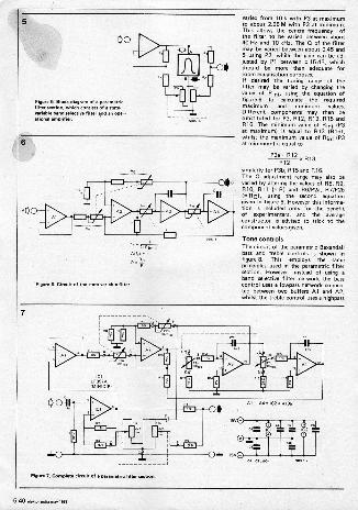
Figure 5. Block diagram of parametric1 Hier section, which consist s of a state.variable.. selective I liter end an operational arnOnfler.
Fiqsren. Circuit of the nee variable filter.
vaned front 10 k with P3 at maximumto about 2.65 M with P3 at minimum.This allows theca ntre frequency ofthe filter to be varied between about40 Hz and 10 kHa. The Q of the filtermay be varied between about 0.45 and5 using P2, while the gain can be ad-justed by Ph between ±15 dB, whichshould be more than adequate forroom equalisation purposes.If desired the tuning range of thefilter may be varied by Bunging thevalue of Rim, using the equation offigure 6 to calculate the requiredmaximum and minimum values.Different component, may then besubstituted for P3, R12, R13, R15 andR16. The minimum value of flint (P3at maximum) is equal to R13 10161,whilst the maximum value of flint (P3at minimum) is equal to
similarly for P3b, R15 and 016.The Q adjustment range may also bevaried by altering the values of RB, R9,610, 011 I= F11 and R6/P2a, R7/P2b(= 001, using the second equationgiven in figure 6. However this informa-tion is included only for the benefitof experimenters, and the averageconstructor is advised to stick to thecomponent values given.
Tone controlsThe circuit of the parametric Baxandall
treble controls is shown infigure B. This employs the sameprinciples used In the parametric filtersection. However, instead of udng aband selective filter network the basscontrol uses a lemmas network connec-ted between two buffers Al and A2,whilst the treble control uses a highness
7
Figure I. Co rpm aimuit of a parametric filter
5.40 ...tor mem Few can

8
Figure 8.0ircuit of Me penmen. ton controls. These re essentially similar to dm parametric filters but usehighness end lowness sections instead o selective finery
9
PCBs& set of COMPONENTS
for project am normally available with
PreetatielECIPONIC4 COPPORMION
82. Proc. Rood Barobnyd00007 PhOPIN:36749/365478
FMunt 8. Printed circuit hoard and component layout for a parametric Illtm
Parts. to Nunn 7 en.
CePaelteraC1' . MKM, MKH Ipoly
carbonate. polyetterlC2,23 a 105141KM. MOHC4,85,06,87,28,09 -100 n
MICK FIKH
eietteriaai. may leas05.41

io
PCBs& Set of COMPONENTS
for projects ore normally available wilh
PreehnielFallONICSCOMORPRON52-8 Proctor Rood. Oomtaym100 001 N108es367059/369418
Figure 10. Printed circuit board and component !avow for the...metric tonecontrols.
Parts list to figures and 10
OFF0IFIR.RI - 100 kF12, f14,146,136 18k1:13,145.10,134 3kB1,110,1411 Bk2
P1,42 . 22 k lin stereoP3,44 k log
.pecifors:
C12 100 n66 n
OB.1n6
.rniconductors.101,1C, LF 358P or LF 387AMINI DIP (Natrona°
1C3 4136 1.a, Raytheon)
orniped in cenain ces.see textin some cases may .by a wire links. text.
11
Figure 11. Interconnection of three.. sections and tone controls to form a complete Peremetric
5.42 etaldor IPBB

*War septet...m.1279 -e 33
ste am Mem de-......SaraaRiaM/RW;lemeemerme
Fmure 12. The completed prototype of the epuelper.
network connected between A3 andA4. The breakpoints of these filterscan be varied, between 50 Hz and 350Hz for the bass controhusing P3, andbetween 2 kHz and 13 kHz for thetreble control using P9. The maximumgain of both controls can be variedbetween Z 15 dB using PI and P2.
ConstructionTo make the equaliser more versatileit was decidedto use a modular formof connruction so that as any filtersections as required could be included.This also means that the sophisticatedtone control section can be used as aunit in us own right by those readerswho do not want an equaliser butwould like a versatile tone controlsystem.Each filter section is therefore builton an individual printed circuit board,Me track pattern and CrPOnent laYontof which is .given in figure 9, whilst aseparate board is used for the tonecontrols, the layout of which is Ovenin figure to The boards are so designedthat, when they are stacked side by side,the output of one board aligns with .
the input of the next. The connectionpoints for the potentiometers are alllabelled with letters, which- correspondto those printed M the circuit diagramsof figures 7 and 8. .
The interconnection of three filtersections and a tone control sectionto form one channel of a completeequaliser is shown in figure 11. If a
stereo version is required then thisarrangement must, of course, beduplicated. To avoid cluttering the dia-gram the potentiometer connectionsare shown to only one filter sectionand the tone control section. However,connections to the other three filtersections are identical. Since the inputsand outputs of each section have thesame DC potential Imo volts) theinput coupling capacitor CI and resistorRI are required only on the boardconnected to the input. On everyother board RI can be omitted and Clbe replaced by a wire link. Since thezero volt rails of each board are inter.connected via signal earth the '0'connection of every board except thetone control should be left unconnected,otherwise earth loops may OCCUr. Onlythe '0' connection on the tone controlboard should be connected. to the Opterminal of the power supply.Zia?' the povver supply the use of a pairof the commonly available IC voltageregulators is suggested. Alternatively, ifthe equaliser is to be incorporated intoan existing system with a 15 V supply.Men it may be possible to derive thesupply to the equaliser from tht.The choice of a suitable housing for
the equaliser is left to the taste 'of theindividual reader. One point, how-ever, is worth noting. Adjustment of theequaliser is fairly time-consuming, butonce the controls are set they shouldnot require readjustrnent unless thereare any changes in the reproductionchain or listening environment. It is
thus a good idea to make the controlstamperiproof, for example by fitting alockable cover plate in front of them,or by fitting spindle locks to theindividual potentiometers-. Alternativelythe knobs could be dispensed withaltogether, the ends of the spindlesslotted to accept a screwdriver and thepotentiometers recessed behind holes inthe front panel.
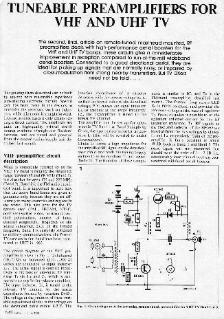
TUNEABLE PREAMPLIFIERS FORVHF AND UHF TV
The second, final, article on remote -tuned, masthead mounted, RFpreamplifiers deals with high-performance aerial boosters for the
VHF and UHF TV bands. These circuits give a considerableimprovement in reception compared to run-of-the-mill widebandaerial boosters. Connected to a good directional aerial, they areideal for picking up signals that are normally noisy, or impaired by
cross -modulation from strong nearby transmitters. But TV DXersneed not be told . .
The preamplifiers described can be builtby anyone with reasonable experienceconstructing electronic circuits. Specialcam has been taken in the designs tominize the necessary work on induc-tors, while alignment is straightforward,because in most cases it only entails set-ting a direct current. The amplifiers arebuilt on high -quality printed circuitboards available through our Readers'Services, and are timed and poweredfrom the master tuning/supply unit de-scribed Dv month.
VHF preamplifier: circuitdescriptionWhat is commonly referred to as theVHF TV band is roughly the frequencyrange between 45 and 68 MHz (Band 1),but also that between 175 and 225 MHz(Band 3). Band 2 is the FM radio broad-cast band. It is important to note herethat the above band limits are given asguidance only, because they are set dif-ferently in many countries and regions inthe world. This also goes for the TVsystem used (PAL, SECAM, MSC,positive/negative video, horizontal/ver-tical polarization, number of lines,channel assignment, frequency of thesound subcarrier, etc.). In the UnitedKingdom, Band 1 is currently allocatedto military communications; the formerTV services in that band have been trans-ferred to UHF in 1983.
The circuit diagram of the VHF pre-amplifier is given in Fig. I. Unbalanced(50.35 SD or balanced (200...300 41cables are connected to input inductorLin. The aerial signal is coupled induc-tively to the base of low -noise RF tran-sistor Ti via Le and Cr, which is con-nected on a tap for impedance matching.The input inductor, Le is tuned 10 therelevant TV channel by the seriescapacitance formed by varactors Dr -DeThe voltage at the junction of these vari-able capacitance diodes is the voltage onthe download cable minus 8.2 V. The
5.44 elelnor intlia may 19.
junction capacitance of a ractordecreases with the reverse voltage on it,so that the lowest value of the downleadvoltage, 9 V, causes the input inductor,Le to resonate at the lowest frequency,i.e., the preamplifier is tuned to thelowest TV channel.The amplifier can be set up for oper-ation in TV Band 1 or Band 3 simply byfitting the appropriate inductor in pos-ition L. (this will be reverted to underConstruction).Choke L3 forms a high impedance forthe amplified RF signal on the downleadcoax cable, and feeds the tuning/supplyvoltage to series regulator T2 and zener-diode Di. The function of these compo-
nents is similar to IC. and DI in theFM -band preamplifier described lastmonth. The forward drop across LEDD. is fairly constant, and provides thereference voltage at the base of regulator
Preset Pe makes it possible to set theoptimum collector current for the RFamplifier transistor, Ti. RF signals atthe base and collector of the BFG65 areblocked from the bias voltages by chokesL2 and Lr, respectively. Gain of the pre-amplifier is fairly constant at about18 dB, both in Band 1 and Band 3. Thenoise figure was not measured, butshould be of the order of 1...2 dB, i.e.,considerably lower than almost any con-ventional wideband aerial booster.
Fig. 1. Circuit diagram of the Ion -noise, remote -tuned, preamplifier for VHF TV Band 1 or

VHF preamplifier: construc-tionCommence the construction with mak-ing L. as required for the relevant fre-quency range (note that this may extendbeyond the indicated band limits). Donot skip the constructional hints in thefollowing paragraphs if you intend tobuild the Band 1 version of the pre-amplifier.
Band 3 025-225 M210:I. Close -wind Ls as 4 turns 01 mm
(SWG19) enamelled copper wirearound a 06 turn plastic former. Use aminiature screwdriver to spread the turnsevenly at about 1 mm. Study the pos-ition of the inductor on the board, andbend the wire ends towards the holesprovided. Use a scalpel or sharp hobbyknife to remove the enamel coating onthe wire ends over a length of about3 mm. Pretin the connections, scratchoff residual solder resin, and pretin oncemorn Check for a smooth, tinned, sur-face.
Fig. 2. Close-up photographs showing induc-tor Li in the VHF Band 3 preamplifier.Fig. gui seen from the side of Lis; Fig. 2brseen from the side of LIP dote the lap madein twisted wire).
PCBs& set of COMPONENTS
for projects are nounally available with
52-C Proctor Rood gomboy.000007 Phones: 362459/269070
Fig. 3. The printed circuit board for the VHF Band 1 or 3 PremndiFeu
Parts list
VHF PREAMPLIFIER. CIRCUIT DIAGRAM:
FIG. 1.
Resistors I t513.1: Di= red -LEDGx e nenerdiode PV 00 mW
51 .10011 3,334.11,1051,10011 T1 heFG65Ran MR 1,0060lien3113
Ray 1 DK Mtluctorsie10013 preset H
Capacitors.
01;C -1n0 miniature ceramic plate; p.tch5 mm.
,C3 -47m 35 V; axial
Semiconductors:
Winding data and materials are stated in the
Miscellaneous'.
CB Type 3s0c45111111

2. Locate the position of the tap on Leat 1 turn from the ground connection.
Carefully scratch off the enamel locally,pretin the small copper area, and con-nect a short length of 00.5 mm(SWG25) enamelled copper wire. Placethe plastic former plus inductor onto thePCB, and bend the tap wire towards therelevant hole. Do not solder any connec-tion as yet. Make sum that the tap doesnot create a short-circuit between theturns of La.3. The input coupling inductor, LIP, is
wound as 2 turns 00.5 mm (SWG25)enamelled copper wire, with a tap at thecentre, Wind this inductor in betweenthe turns of LIB to assure the necessaryinductive coupling. Insert the wire belowthe turn of LIB that has the tap on it.Wind the wire upwards into the freespace between the turns of Lie, until itis opposite the connections of L.Draw out about 4 cm of the wire, fold itback again towards the former, and windthe last turn upwards into LIB.4. Use precision pliers to twist the 2 cm
long wire pair that forms the tap onLie. Hold the end of the wires in thepliers, and carefully revolve these in yourhand until the wires cross practically atthe body of the plastic former.5. Place the former with the inductors
on it onto the PCB, and revolve bothAL and LIB until all six wires can be in-
serted in the respective holes. Scratch offthe enamel coating from the tap and theends of Lie, pretin, clean again byscratching, and ensure a smoothsoldering surface, Pmss LIB together tolock up the turns of L.A. The final ap-pearance of the completed inductor isshown in the photographs of Fig. 2.Drill and file the hole that receives theplastic former. Fit the wires of L intothe respective holes, and verify correctcontinuity. Do not use a core in L.
Band I (45-68 MHz).For the lower frequency range, L iswound on a Type T50-12 ferrite core(012 mm) from Micrometals.I. Wind LIA as 8 turns 00.5 mm
(SWG25) enamelled copper wire, witha twisted centre tap created as discussedabove.2. Wind Lie as 20 turns of 00.5 mm
(SWG25) enamelled copper wire, witha twisted tap at 4 turns from the groundconnection.3. Fit the complete inductor onto [hi
PCB, making sure that the windingsremain secure on the ferrite ring.
Chokes La, L3 and L. are identical forboth versions of the VHF preamplifier.They are wound as 4 turns 00.2 mm(SWG36) enamelled copper wire throughsmall ferrite beads (length: approx.3 mm).The printed circuit board for the VHFpreamplifier is shown in Fig. 3 (note thatthe component overlay is relevant to the
"V.2F6Tergerierir may 1988
on for Band 1). Completion of thepreamplifier should not present prob-lems. Grounded component wires andterminals are soldered at both sides ofthe board. Coupling capacitors CI andCr are miniature, plate or disc, ceramictypes with a lead spacing of 5 mm.Mount these as close as possible to thePCB surface, Conversely, mount T, in amanner that rules out any likelihood ofa short-circuit between the T05 case(which is at collector potential) and thePCB ground surface. Finally, fit a15 mm high brass or tin metal sheetacross Ti as indicated by the dashed lineon the component overlay.
The UHF preamplifier:circuit description.The circuit diagram of the low -noise,remote -tuned, UHF preamplifier formasthead mounting is shown in Fig. 4.Like the VHF booster, this amplifier isbased on the Type BFG65 RF transistorfrom Volvo (Philips/Mullard), but inthis application has tuned input and out-put circuits. The tuning voltage forvaactor pairs DI -D) and Di -Da is ob-tained as in the FM -band and VHF pre-amplifiers, namely by subtracting thefixed drop across a zenerdiode from the
voltage carried on the downlead coaxconnected to the master tuning/supplycontrol. The tuning range of the ampli-fier covers the entire UHF TV band(470-860 MHz). The shaded rec-tangular blocks in the circuit diagramare straight lengths of silver-plated wirethat function as inductors (L; La).Balanced aerials or feeder systems with atermination impedance of 200...300 Stare conected to Lin This coupling in-ductornis omitted when the input signalis unbalanced (50...75 0). In this case,the centre core of the con cable is con-nected direct to a matching tap close tothe ground connection (cold end) ofLk. Regulator ICI ensures that Ti is fedwith a constant supply of 8 V, while P.is used for setting the optimum collectorcurrent (this can be mad on a microam-meter connected to test points TPI andTP2).The UHF amplifier has a typical gain of12 dB and, like the VHF version,achieves a noise figure that beats the vastmajority of wideband aerial boosters.
The UHF preamplifier:constructionThe UHF TV band preamplifier is con-structed on the PC board shown in
Fig. 4. Circuit diagram of the preamplifier for UHF IV reception.

Fig. 5. Track layout and component mounting plan of the PCB for the UHF preampli
Fig. 5. Study the component overlay,and bend Lin (if required), La and Lxto size from 01 mm silver plated copperwire (CuAg). Do not solder these induc-tors in place, however, until they runstraight over the full length, and are pos-itioned so that the top of the wire isalways exactly 3 mm above the PCB sur-face. Fit leadless disc or rectangulardecoupling capacitor Cs in the slot pro-vided in the PCB. This (brittle)) capaci-tor is soldered once at the track side(connection to Lr), and twice at thecompOnent side (ground and, again,Ls). Now position the RF transistor, T,in between the wire inductors, and solderthe 2 emitter terminals direct to theground surface. Carefully bend the col-lector terminal upwards, cut it to length,and solder it to the tap on Lu. One ter-
.- minal of coupling capacitor Ce is alsoconnected direct to this junetidn, whilethe other terminal is secured in a PCBhole-see the photograph of Fig. 6.Bend the base terminal of T, upwards,and carefully cut this to a length ofabout 2 mm. Solder a 1nF SMD capaci-tor, Ck in between the tap on Lin andthe base terminal. R, is also soldereddirect to the base junction. Fit a 15 mmhigh screen across Ti as indicated onthe component overlay.Wind choke Li es 6 wens 00.2 mm(SWG25) through a small (3 mm long)ferrite bead. The fitting of the remainderof the components is straightforward,
Pam hi
UHF PREAMPLIFIER. CIRCUIT DIAGRAM: FIG. 3.
Resistors 1,5%):
=223Re=100131:13;fl,P8-1001,
=1K0 preset H
Capacitors.
Cues,. WO
Ca= 150Cc=i1n0
lead le
at aure plate cseWermic.ss ceramic i or rectangular,.
Cs= 160: 16 V; axialCs. 1p, 40 V: axle,
=436; 35 Vi axial
SemiconduAorsi
Di. Dv incli=3320E8Os= tenerdimle 8V2; 000 rnWIC1=781.08111=6FGC5
IncluctorH
Winding data and m
Miscellaneous:
PCB Type 360006
Fig. 6. Top view of the line induelors in thepreamplifier for UHF TV.
and should not present problems. Besure, however, to observe the polarity ofthe 3 electrolytic capacitors and the 5diodes!Figure 7 shows completed prototypes ofthe VHF and the UHF aerial boosters.
Setting upThe setting up of the preamplifiers mere-ly entails adjusting the collector currentof the RF transistor, and finding outwhich value of the tuning voltage cor-responds to a particular TV channel.
VHF preamplifier:Insert an ammeter between the collectorof Tr and Lk. Connect the powersupply/tuning unit described last month,and set the output voltage to 20 V. Ad-just Pi for a reading of 5 mA, thenverify the presence of about +11 V onthe varactor junction. Vary the tuningvoltage, and verify that the collector cur-rent of Ti remains constant. The LEDwill light dimly.Connect the preamplifier to the aerialand the supply/tuning unit. Also con-nect the TV set, and set up a tuning scaleby marking the channel numbers as afunction of the tuning voltage. In thecase of the Band 3 preamplifier, the tun-ing range can be corrected by carefullycompressing or stretching the turns of
The collector current of Ti is optimizedby tuning to a weak transmission, andsetting Pi for minimum noise. Ws set-ting is typically found at collector cur-rents between 3 and 10 mA.
UHF preamplifier:Connect a millivolt meter to TP1 andTP2 as shown in the circuit diagram. SetP, fora reading of 500 mV. Make notesof the tuning voltage required for anumber of TV channels in the UHF
eleho, 5.47

band, and provide a UHF tuning scaleon the master supply/tuning unit.
General considerationsThe values stated for the operating cur-rent of Tt am given as a compomise be-tween a low noise figure (low collectorcurrent), and high amplification in com-bination with good intermodulationcharacteristics (high collector current).The collector current may, therefore, beset to different values to suit the appli-cation in question.
As stated in last month's article, there islittle point in installing the remote -tunedpreamplifiers in any place other than asnear as possible to the relevant aerial.This is the only way to prevent the at-tenuation introduced by the downleadcoax cable degrading the system noisefigure. The preamplifiers described havesufficient gain to bring the system noisefigure down to practically the preampli-fier noise figure, but only if they areproperly aligned and installed. B
Readers interested in TV-DXing am ad-vised to contact the British AmateurTelevision Club Mr Dave LawtonGOANO "Grenehurst" PinewoodRoad High Wycombe BucksHPI2 4130.
Fig. 7. Proloispes 55 the V3.7 P(right).
mplifier Penal 3 version), a. the UHF preamplifier
RADIO COMMUNICATIONSFOR THE FUTURE
by Dr. Chris Gibbins, Rutherford Appleton Laboratory
Overcrowding of the radio spectrum is severely restricting the re-liability and information -carrying capacity of existing communi-
cations systems. But moving to higher frequencies, where there ismore room, brings a different set of problems to do with theatmosphere and weather. Research at the UK Science and
Engineering Research Council's Rutherford Appleton Laboratory iscompiling valuable data for the design of systems for the future,
exploiting frequency bands that are so far little used but for whichthe necessary technology is already available
A massive expansion in radio communi-cations over recent years has generatedan ever-increasing demand for morechannels, and those channels am hwingto carry more and more information, beit voice, television or other kinds of data.The net result is that the radio spectrum,a restricted resource, is fast becomingovercrowded. This creates problems ofinterference between adjacent channels
5.48 tedre ee
(as anyone who listens to short-waveradio, especially at night, will know well)with reduced reliability. Them is anadditional side -effect of such over-crowding: the bandwidth available toeach channel, which determines theamount of information that can betransmitted, is severely limited: That initself restricts both the capacity and thereliability of communications systems.
Millimetre wavesA remedy for these problems is to befound in exploiting higher and higherfrequencies, made possible through thedevelopment and availability of newtechnologies. Communications now ex-tend well into the microwave region ofthe electromagnetic spectrum (fre-quencies up to 30 GHz) and even beyond

Attenuation of micrmvave and millimetrewa e radio signals by the Earth's almospherat ea level. Molecular attenuation is presenall the time and is produced by water vapou(H 0)9122.d 183 Wiz and by °M. (Osat 60 a. 119 GHz; there are many more othese 'absorption lines, mainly from walempour, at even higher frequencies. The rangeof the highly variable attenuation caused byrain is shown by three representative curvesfor light drizzle, lyrical m ana inHHthunderstorms. The arrows at the bottomingdicate
the frequencies at which the Rather -ford Appleton Laboratory is makingmeasurements.
into the millimetre -wavelength region(frequencies from 30 to 300 GHz). Theseregions of the spectrum are still rela-tively uncrowded, particularly at thehigher frequencies, and the bandwidthsavailable are so large that they open upthe possibility of new communicationschannels with a capacity for carryinghuge amounts of information.But use of the microwave and millimetrewave regions of the spectrum for com-munications brings an additional set ofproblems not met with at lower fre-quencies. The Earth's atmosphere startsto interact with the radio waves, resultingin attenuation of the signals which mustbe taken into account in the design ofsystems. There are two distinct and quitedifferent effects, which are shown in thefirst diagram. First, the molecules of ox-ygen and water vapour in the atmos-phere absorb radiowaves at certaincharacteristic frequencies. This is knownas resonant absorption. They re -radiatethem isotropically, that is, equally in alldirections, a fraction of a second later;this means that the signal is attenuatedthrough the loss of directivity andcoherency. The second effect is that rain-drops, hail and snow scatter the signals,thereby attenuating it still mom. This ef-fect is non -resonant and increases withincreasing frequency, as the wavelengthdecreases and becomes comparable withthe sizes of raindrops; at that point thescattering process is most efficient andsignal attenuation is greatest. The firsteffect, molecular absorption, is presentall the time, and changes only slowly
with varying temperature, pressure andhumidity. A great deal of research hasbeen undertaken into this phenomenonand the effects of molecular absorptioncan now .be predicted fairly accurately.So the designer of communicationssystems can take reasonably accurate ac-count of attenuation by oxygen andwater vapour when assessing the overallperformance of microwave andmillimetre -wave links.
Fade marginSignal attenuation by rain and otherforms of precipitation, however, presentsa quite different problem. Precipitationis a highly variable phenomenon; changing both in time, space (thatgeographic location) and intensity. Thismakes it much more difficult to take ac-count of rain attenuation in designingsystems. The problem is generallytreated statistically instead of by the sortof exact calculation that can be used formolecular attenuation. The systemsdesigner specifies a level of reliability fora particular communications link: forexample, the link might be required toprovide acceptable voice communicationfor 99.9 per cent of the time, or accept-able television transmission for 95 percent. That means the users can toleratethe service being unavailable for 0.1 percent or 5 per cent of the time respect-ively. The designer then needs to knowwhat level of signal attenuation tut beexceeded on the link for these smallpercentages of time. This is known as the'fade margin' which the link must beable to overcome when providing an ac-ceptable signal-to-noise ratio, to achievethe specified level of reliability. This, inturn, has an impact on the transmitterpower, receiver sensitivity and the size ofthe antennas, which in the end affectsthe overall cost of the system. It istherefore of paramount importance that
the systems designer should haveavailable the most accurate informationfrom which to derive the necessary fademargins, to achieve the most reliable andcost-effective design.Fade margins are not easily calculableand in general tend to be empirically de-rived from transmission measurementscarried out over long periods. A greatdeal of work has already been done atfrequencies up to about 40 GHz, andthere are extensive data banks fromwhich the necessary statistical infor-mation and service predictions can bederived. For example, the InternationalRadio Consultative Committee (CCIR)at Geneva collates, distils and publishesinformation of this kind. -At higher fre-quencies, however, there is a markedpaucity of data.
Foundation for systemslb provide the necessary information onterrestrial radiowave propagation, theRutherford Appleton Laboratory has setup an experimental transmission rangeat its Chilbolton Observatory near An-dover, in southern England. This facility,represented schematically in the seconddiagram, works on a number of linkstransmitting over a distance of 0.5 km atfrequencies of 37, 57, 97, 37 and210 GHz in the millimetre -wavelengthregion of the electromagnetic spectrumand at wavelengths of 10.6 tan in theinfra -red and 0.63 pm in the visibleregion. Frequencies of 37, 97, 137 and210 GHz were chosen as representativeof those parts of the spectrum where at-mospheric attenuations due to oxygenand water vapour are low; such parts areknown as atmospheric 'windows' andhold out the opportunity for cost-effective, widebandwidth communi-cations. The 37 GHz channel can alsoprovide the means for comparing theresults from the 500 m range with exten
Mhematic diagram of the 500 in experimental range at Chilholton.mks, innames :see 5.49
sive measurements made at this andlower frequencies at other places and byother workers. The 57 GHz frequency,on the other hand, is near the 60 GHzoxygen absorption band, where veryhigh attenuations of up to 15 dB(decibels) per kilometre occur, whichmeans 97 per cent of the signal is at-tenuated at a distance of one kilometrefrom the transmitter and only three percent remains to be received. Such regionsof the spectrum could be used for securecommunications, for maniple wheretransmission range should be restricted,or for multiple repeated use of a fre-quency in a dense urban environment,because the atmosphere produces extraisolation between links operating at thesame frequency.In addition to the transmission links, theChilbolton Observatory compiles a com-prehensive set of meteorological data,including measurements of temperatureand humidity at a number of places andheights above the ground. There arethree rapid -response. rain gauges, whichmeasure the rainfall rate at differentpoints along the range at 10 -second in-tervals, while a fourth rain gauge isequipped with heaters to assist themeasurement of snow during the winterand hailmin the summer. A distrometermeasures the distribution of the sizes ofraindrops, important in the developmentof theoretical models to describe rain at-tenuation; a microwave refractometermeasures the refractive index of the at-mosphere, which affects the level of scin-tillation, the name given to small, veryrapid fluctuations in the received signalmover. The meteorological observationsare completed with surface pressure andwind speed and direction.Outputs from all the links and sensorsare coupled via an interconnecting com-puter bus to the main data -collectioncomputer, which records all themsurements on magnetic tape every 10
ends. Additionally, when attenuationdue to precipitation is detected on therange, the outputs from the transmissionlinks are recorded separately at a rate of100 measurements per second. Thedaracollection computer also initiatesautomatic calibrations of the links every6 bean. All magnetic tapes are sub -
seuently calibrated and verified on ain -frame computer, and the data files
put into an archive for anlysis.The 500 m range, then, is a well in-strumented open-air laboratory designedto study in detail the interaction betweenradio waves and the prevailing weatherconditions, by providing comprehensivepropagation data for a distance overwhich meteorological conditions areessentially constant. The range has beenin operation for about three years and asubstantial data base of propagationdata has now been accumulated. It is be-ing used for a variety of studies aimed ata more detailed understanding of the
5.50 cloro rr.W um
The transmitter cabin at Chilhollon. Hoodkeep min off the windows through which thsignals are transmitted. The transmitters aremounted on benches supported independentty from ground, inside the four coneretWars. This prevents vibrations in the .binaffecting the equipment. The anemometeand mne monted on top of the cabinumeasure wind velocity.
various phenomena which may affectthe reliability of communicationssystems, and providing the statistical in-formation required by systems designers.
Two main analysesThe data base is being extensivelyanalysed in two different ways. Detailedstudies are being madeevents, such as particular rain storms,snow storms, fogs and so on, to learnmore about the way radio waves pro-pagate through such phenomena. Fromsuch studies it will be possible to developmore detailed and accurate theoreticaldescriptions than so far exist of the wayvarious kinds of precipitation and soforth interact with radio waves. Thesetheoretical models, as they are generallyknown, can then be used to predict whatmay happen on proposed new communi-cations links in areas where little, if any,propagation or metereological data m-ist. The second mode of analysis isaimed at providing the kind of statisticaldata necessary for the most cost-effective design of new communicationssystems, and to provide a statistical database for testing and validating theprediction techniques being developed.Analyses based on individual events areclassified according to the type of event,for example rain, snow, hail, fog or scin-tillation. Extensive studies on rainalready indicate a general overall agree-ment both with similar studies coducted elsewhere and the theoreticalmodels which so far exist, such as thoserecommended by the CCIR. Never-theless, certain significant differenceshave been found, which may possibly beattributed to the differences in climatebetween southern England and theplaces where other studies have been
made. Understanding suchclimatalogical differences is very import-ant in being able to develop predictionmodels if they are to be applied to anyplace on Earth. We feel that our workwill help considerably in achieving this.Attenuations produced by rain vary con-siderably, of course, because they de-pend on the features of the rain. Lightdrizzle may attenuate the signals by onlya few per cent over the 500 m range,whereas intense thunderstroms can at-tenuate by more than 30 dB km-, at97 GHz, for example; in other words,only 0.1 per cent of the signal remainsafter a distance of one kilometre. For-tunately, such events are very confined.
Snow and fogOf great interest is the effect that mowstorms have on millimetre communi-cations. There is shortage of such dataand the few results available show widevariations. Snow is generally difficult tocharacterize quantitatively with regardto shape, size and wetness of the flakes.These characteristics vary widely, andwhen snow is carried by the wind itbecomes difficult erin to measure dim -rive deposit rates. However, we havedeveloped a rapid response snow gaugewhich is producing very encouragingresults. The effects of wind are kept aslow as possible by surrounding the gauge
reduces wind speedsclose to the gauge and so improves theefficiency of capture. Using this tech-nique, we find good correlations be-tween attenuation and snowfall depositrates. Results so far indicate that whensnow is very dry the attenuations are low,compared with rain, for the sameamount of liquid water deposited; butfor wet snow, attenuations can be con-siderably higher. The attenuation clearlydepends not only on the amount of li-quid water falling, but also on the degreeof wetness of the snow flakes. Con-siderable effort is being devoted to tryingto characterize this in terms of othermeteorological parameters such as airtemperature, so that empirical relation-ships can be developed to help theprediction of attenuation.Fogs, on the other hand, affect themillimetre links very little; thewavelengths are much greater than thesize of the water droplets and the scatter-ing process, which causes the attenua-tion, is not significant. In general, theattenuations found at millimetrewavelengths are only a few per cent atthe 500 m range. At infra -zed and opticalwavelengths, however, very severe at-tenuations, of more than 80 dB km -often occur in the visible range in fog,representing a risibility of only about200 rre only one millionth of one percent of the signal remains at a distanceof one kilometre from the transmitter.

Gas flaresThe 500 m range can easily accom-modate a variety of differentmeasurements or experiments fromother interested groups, especially as allthe instrumentation and the data collec-tion system are based on a universal in-terface standard. As an example of this,an interesting and novel investigationwas carried out into millimetre -wavepropagation through flames, in collab-oration with one of the oil companiesoperating in the North Sea. The problemwas what effect gas flares on the drillingplatforms might have on the communi-cations systems. A large flame wasgenerated, about three metres wide,three metres high and half a metre deepand the signals were transmitted throughit. Little effect was observed at thelowest frequencies, though large attenu-ations occurred in the visible range.There was, however, a general increase inthe level of scintillation of the signals,which might possibly be of concern atthe very high frequencies but of littlesignificance at the frequencies at presentin use for communications systems.The other type of analysis of results isaimed at obtaining the kind of statisticalinformation needed for direct appli-cation to communications systemsdesign, for example finding out whatfade margins should be allowed for givenlevels of operational reliability. This is
nec importanta longterm project, becauseit is important to find an average over ex-tremes of the prevailing meteorology andit can be done reliably only over anumber of years. Statistical data now be-ing accumulated include such infor-mation as the 'percentages of time thatvaious levels of attenuation are exceed-ed,r from which fade margins can bedirectly derived; probability distribu-tions of the duration of fades to yield in-formation on the length of data`dropouts'; the times between fades,which tell us how often deep fades arelikely to occur; and the rate of change offading, which indicates how rapidlysignals are likely to change, which is par-ticularly important in digital radio com-munications systems. The propagationstatistics are complemented by similarstatistics of meteorological parameters,especially of rainfall rates. Direct com-parison of these two sets of simul-taneously obtained data then enablespropagation conditions to be predictedsimply from rainfall data, which is rela-tively easy and inexpensive to obtain andis measured routinely by weatherbureaux in most countries of the world.
Future workThe information obtained on the 500 mrange will be of immense value in pro-viding propagation statistics and in
The 97 Ms receiver with its 15 em diameter antenna and swan -neck wavegoide reed. Its solid-state toast oscillator is mounted on a heat sink on the right-hand side. A battery -operatedpower supply biases the receiver's Schottky -barrier mixer to its most sensitive operatingregion.
developing propagation models andprediction techniques for planningfuture communications systems. Thedata is being collected over a relativelyshort distance, chosen deliberately to en-sure that the meteorological conditionswould be nearly constant over the range.In general, however, practical communi-cations links Operating at millimetrewavelengths will have much greater pathlengths, perhaps up to several tens ofkilometres or more, depending on thefrequency.It is generally found that precipitation,the dominant source of fading in themillimetre region, is characteristicallynot homogeneous or uniformlydistributed horizontally. Widespread(stanform) rain is found to contain im-bedded convective cells with higher rain-fall rates than the surroundingstratiform regions. Such cells tend, onaverage, to be about 12 km apart andfrom two the three kilometres indiameter. As a result, it is not practicablesimply to scale the data obtained on the500 m range to path lengths of morethan about two kilometres.To obtain data over the longer pathswhich would be used in operationalmillimetre -wavelength communicationssystems, an additional link is beingdeveloped to operate in conjunction withthe 500 m range over a path of aboutseven kilometres. This will provide dataon path -length scaling, in which the500 m data are applied to longer, more
practical link lengths; at the same time itwill produce a data base for validating_practical prediction techniques. The linkwill operate at frequencies of 55 GI -1.,near the peak of the oxygen absorptionband, and 95 GHz, in an atmospheric'window. These represent two regions ofthe radio spectrum in which there is con-siderable interest, for reasons alreadymentioned, to do with their applicationto specific types of future communi-cations systems.These two sets of multi -frequency trans-mission links, operated simultaneously,will enable us to build up one of themost comprehensive propagation database for future millimetre -wave. ter-restrial communications systems design.The detailed and extensive programmeof data analysis now going on and beingproposed will yield essential informationfor expanding terrestrial radio communi-cations into the millimetre -wavelengthregions of the radio spectrum for theforeseeable future.
emm, nay. mw oor 5.51

COMPUTER -CONTROLLED SLIDEFADER (1)
Revenge yourself on giggling friends and relatives joined to watch and criticize your clumsy slidepresentation.
This project gives the creativity you put in your colour slides an extra dimension in the true sense ofthe word. A chance for all mindful photographers and slide makers to stun their audience with a
dazzling show of fading and dissolving images, sudden or gradual colour changes, the repeating of"theme" slides, and many more special effects, achieved by intelligent control of four slide projectors.
The main difficulty in making a slidepresentation is re capture the attentionof the audience. Television, the motionpicture, and modern advertisement tech-niques prove beyond doubt that thedegree of attention depends strongly onthe rate at which the human mind ap-pears to perceive changing images.While appreciating the difference Mcharacter and objective between a well -prepared slide presentation and, say, avideo clip, the former is often needlesslystatic. It is, of course, true that this isoften useful for educational purposes,where it is required that an image beshown as long as necessary to allow forexplanatory comments, but the showsoon becomes dreary when pictures areabruptly changed with the operator oc-casionally forced to go through all theprevious ones before he can pick out theslide that requires repeating for ad-ditional comment.
-The computer controlled slide fader de -
5.52 now om :no Inn
Fig. 1. Functional blocks in the computer.controlled slide fader system.

lcribed here is sure to add motion andiveliness to your next slide presentation.The effects that can be obtained with itare in the hands of the operator: in itsbasic version, the fader enables com-puter control of the lamp intensity in 64steps, and the reverse/forward motion ofthe slide caller in any one of up to fourslide projectors-see Fig. I. The hard-ware required for this is relatively simple,and can be extended or simplified to per-sonal needs. The whole slide show canbe designed, directed and prepared byprogramming a computer in BASIC.Each slide projector requires ifs own 8 -bit output port. Not many computershave 4 such outlets, however, and requireequipping with extension circuits pub-lished, or to be published, in ElektorElectronics:
MSX systems:32 -bit I/O and timer cartridge: ElektorElectronics January 1987, p. 53 ff. Con-trols up to 4 projectors.
6502, 6800 and Z80 based systems:Universal I/O bus: Elektor Electronics,May 1985, p. 35 ff. 8 -bit I/O bus:Elektor Electronics, December 1985,p. 20 ff. Controls I projector. IBM PC XT and compatibles: to bedescribed in a forthcoming issue ofElektor Electronics. Controls 4 projec-tors. Centronics port: to be described in aforthcoming issue of Elektor Elec-tronics. Controls up to 4 projectors.
Circuit description of thelamp dimmerSlide images can be faded in and out,just like gonad, if the intensity of theprojector lamp can be controlled insmall steps. Figure 2 shows the circuitdiagram of 1 of 4 identical dimmers. Atthe heart of the circuit is the TypeTCA280 dimmer chip, whose basic oper-ation is discussed in reference m. Theintensity of the lamp driven by the triacis an inverse, but non-linear, function ofthe direct control voltage applied to pin5 of the chip. The minimum value of theinput voltage, +2.5 V, gives maximumintensity, while the lamp is quenched at+5 V Circuitry on board the TCA280Aarranges for the perceived lamp intensityto vary gradually in accordance with thechange in the applied input voltage.The dimmer is powered from the avail-able 24 VAC connections on the lamptransformer in the projector. The triac isfitted as an external component to avoidhigh currents being carried on the PCB.The Types TIC236 and TIC246 are usedfor lamps of up to 150 W or 250 W, re-spectively.
Circuit description of thecontrol interfaceThe circuit diagram of Fig. 3 shows 4identical control channels: one for eachprojector informationfor each channel is obtained from an 8 -bit output port (A, B, C, or D). With
Fig. 2. Circuit diagram of the TCA280 based lamp dimmer.
reference to the upper channel, A, 6 bits,AO... AS incl., am used for controllingthe lamp intensity at a resolution of 64(26) steps. The 2 remaining bits, A6 andA7, control the relays for reverse andforward motion of the slide carrier onthe projector.Digital to analogue converter (DAC) IC:accepts the 6 -bit binary informationfrom the computer, and translates thisinto a corresponding direct voltage be-tween 0 and +2.5 Von the output, pin4. The maximum value is derived from areference voltage source set up aroundKI7 and 4 series -connected silicondiodes Dr... D6 incl. The forward dropon each of these is approximately0.62 V. When the computer port sendscontrol value 00n, 40n, or 80m to theDAC, all 6 inputs DB0...DB5 incl. onthe DAC are pulled low, so that the con-verted analogue output voltage is 0 V.The maximum value of the output volt-age, Lt,r (+2.5 V), is available when allDAC inputs are programmed logic high,i.e., when the computer sends 3Fii, 7Fiv,or BFa (it makes no sense to activatebits 6 and 7 simultaneously).Opamp IC2 is set up as an invertingamplifier connected to the output of theDAC. Its function is to invert and shiftthe analogue output voltage span of 0 to+2.5 V into the corresponding dimmerinput span from +5 V down to +2.5 V.The amplification of the opamp is,therefore, -1. With preset Pi set to thecentre of its travel, the voltage at thenoverting (+) input is +2.5 V. Thisis the lowest output voltage of theopamp, resulting in maximum illumi-nation of the lamp. The use of the in-verting and span shifting opampfacilitates the programming on the com-puter, since the lowest and highest valuessent to the DAC correspond to minimumand maximum illumination of the pro-jector lamp. A preset is used rather thana fixed potential divider to enable opti-mum matching of the dimmer to thelamp in the associated projector.Bits 6 and 7 in the byte sent to eachchannel arrange the forward or reversemotion of the slide carrier via relays Raiand Rev. The contacts of these form anSPDT switch connected to pins 3 and 5on the relevant 5 -way DIN socket at theoutput of the controller board. Theintensity control signals for the 4 dim-mer boards, and the system ground, arealso carried via the DIN sockets.The pin -out on IC) is in accordance withthat on the previously mentioned 32 -bitI/O and timer cartridge, so that this con-nects direct to the 4 -way slide controllerboard. For non-MSX computers, theconnection of the slide controller is, un-fortunately, a matter of finding the rightbits and connections at both ends of thecable.The 5 V supply for the circuitry on thecontroller board is obtained from thecomputer via pins 21 and 22 on Ks.
s,stierisas.ss ism 5.53

Fig. 3. Circuit diagram of the 4 -way computer interface
5.54 1...wssa

Porte fist
MAIN BOARD ICIRCUIT DIAGRAM: FIB 31.
Resistors Ii5161:
Ri.Rs.RwReie:RimRIAllis -120KRe:WeRT:WeRrullimR, m000.606ferTP2K)Pr ...Ps incl.-250K or MN preset H
Capacitors:
Ct -Ca incl.P10Cs:Cs...1002 16 V
Semiconductors:
0...)1)14 Inel. -104148Ti .i BC543BICRICuIC elCr -70436E(Ferranti)
CA3130
Miscellaneous:
Kr ...Ka Incl.. S.way angled DIN socket1180.1 for PCB mounting.
Ks- 50 -way angled header; 2 saws of 25 pinyfor PCB edge moulting.
Am ...Rea incl.- SPOT relay fee PCB mount-ing. e.g. Siemens V23101,13003 -B101.
PCB Type 07260
Rule OM
DIMMER PCBs ICIRCUIT DIAGRAM: FIg. 21.
Resistors 14 661:
110-4700: 0.6 WR3:R4.11308Rs -22K110.330KRsP1504Ra.270KRe -82KRoe 150R
Capacitors:
C1=47014 Fe vCs -102 Mee text)C3P1n5
Semiconductor:
131.11.14001ICIPTCA2130ATru YTIC236 or riczao (sea tent)
4
411E1010N
PCBs& Set of COMPONENTS
for project ore norm* available with
PreCiOUSCRACISONICS COWMAN.52.0 Proetorlicaci. Bombay -400007 Phones: 363459/3694711
E4
ef1Y-e-el
gill
te,. wry+
0
sip
161 14144 d 46 t
dE5,),
gip: 14°,0
rnm,isc--,,r-
n*1.'.2
44. '''[: rCt4 RIF?
le-ti4-....... --./nA.0
,NMI-ntfrA
Fig. 4. This PCB Is used for building the interface and 4 dimmers.
eleinerIndla T., IBM 5.55

Construction: 5 boards in 1The ready-made printed circuit board ofFig. 4 is cut in 5 pieces to obtain 1 Mier -face board, and 4 dimmer boards.Commence the construction by popu-lating the dimmer boards according tothe component overlay and the parts list.Mount a 1µF and a 2200F capacitor inparallel if the 1.2µF type in position CJis difficult to obain. Electrolytic capaci-tor Ci and triac are fitted Os ster-nal components. This enables the triacto be cooled effectively, while avoidingtracks carrying lamp currents of severalamperes. The dimmer board and thetriac should be mounted in a suitableloaction inside the slide projector. Ametal surface near the fan is, of course,ideal for mounting the triac because itforms a heat -sink (do not forget to insu-late the triac with the aid of a micawasher). Figures 5 and 6 illustrate themounting of the triac and the dimmerboard in a slide projector Type Diammor1500 AF.In some cases, the existing DIN socketon the slide projector may have to be re-wired in accordance with the pin -out onthe socket fitted on the controller board.If this is impossible, calms desirable, itis a relatively simple matter to mount anadditional DIN socket for ready connec-tion to the interface. Whatever solutionis adopted, be sure to know exactly howthe slide carrier control system is ac-tuated externally. In case of doubt, it isrecommended to consult the usermanual supplied with the projector.Universal 5 -way DIN cords as used foraudio equipment are perfectly adequatefor connecting the slide controller to theprojectors.The completion of the 4 -way controllerboard is straightforward. Note the nee ofPCB mounted DIN sockets, which makefor a compact board, obviating the needfor extensive wiring. The unit can be fit-ted in a suitable ABS enclosure, observ-ing that the intensity span presets,Pi ...Ps incl., are easily accessible foradjustment purposes. Figure 7 shows asuggestion for the front panel lay -out.
Over to you: softwareIn principle, all effects in a slide presen-tation are based on 3 operations, namelyvisual mixing of slides, arranging theorder of the slides, and lamp intensitycontrol. As already stated, the numberof possible effects depends solely on thecreativity put into the computer pro-gram. It is, for example, possible torevert to an early slide in the show by re-verse shifting of the slide carrier in pro-jector number 3, whose lamp is turnedoff, while projectors numbers I, 2 and 4are used for the current images. Thiscalls for a software slide counter on eachchannel to keep track of the slide numhers, and hence the forward/reverse ma-
5.56 el.., India ewer
I/ scum as TEST PIOCIM Ma SLIM MU2D OMIT A -Z31 MD 0(151,C115).1115)AO POR 14 TO AMES BlITIALITATIM51 A=I"16
41 111.1.4144 111.1.4144 11(2.1,4)44 113.1.4)44T. C11114144 C(IP4)=7.4 C1241.41.1114 U3aIMI.114
tune911 ON SNP COMB 590 STCP ON
UM FOR VA TO 15 SLIM 11011DITICIIS
Ill OM MX1,255 OUT C(X),11 OAT COD ,7 011T C(X),3121 BIT 1/00,11
131 III)4IN lifft151 P4 1=1
161 Off MT DOSM 261,3M,34,371,111,431,461,491,571,551171 VOR 1=1 TO lb
1111 AT II) Off191 1110(T
210 016,"11171005'd(817,"11101r1814"51111-",MT9,"599e":11IT111,1515111.220 MT ON
2311 secure 10,6 PlIIPPROJICTORi",Peli" " LOCATII 10,1 :
"2.41 LOCATE 11,11: PRIBPSTIP SILIddh. 1=11 11,10
PRIIITT1111111:;):1;251 COTO 2211
270 109.1(P) -I IF 111910 no UP)*201 011T
291 MUM
310 I111.1(114 If IIP))63 fin 10143310 911 MP1.I1P) : 1187"-"331 11111111
351 OUT 1111,64 11014361 RETUPS
3711
3(11 We DIP),I18 : /Vi" : 110/4391 MRIII
611 DDT 0(9)911 X1=- : 111114
421 Wing
CAT 1 111110151IT -
ITT 2 =WM r
IT 3 cease UMW
III 4 eaten PPIPARID
- ICU 5 CIPICI OFF
KIT 6 MINIM DiffurroedN PeP-1 : IF Pro IRE 1,15450 MTNdI ----- ...... ........ SET 7 NM PROficroo470 IP I,15 7919 114480 RIME
518 ail EMI 141511 BIM521
531'441 /063 MEI 1143Sell RIM!
501 P4 : Xe1
570 FOR fell TO 15: OUT 0111,1 11114: MIXT581) ROW
61)11 FOR 14 TO 15: OW 0111,1:611 017119141BE A-1191111
620 d5 : MD
RFT 8 MIXT STUD SIZE
ED 9 INORRASE STOP 51Z¢
MT 11 MIT
STOP !OMNI
Tabk I. MSX BASIC test program for the slide fader.

Fig. 5. The dimmer hoard fitted next to the fan motor in a slide projector. C. is mounted at Fig. 6. An ideal lora0on for the not trineSome filing is required to fit the the heat -sinkbetween the sides of the fan enclosure.
the track side of the PCB.
tion of the carrier. A library of routinescan be written for fade-in and fade-outeffects timed by the CTC (counter/timercontroller) on the MSX I/O & timerboard.Programmers should have little diffi-culty spotting and adapting the slidecontroller routines in the test program ofTable J. This program runs on MSXcomputers fitted with at least one 1/0 &timer cartridge. Part 2 of this article willdetail the use of 4 cartridges, so that thesame program tests and controls a maxi -
of 16 projector channels.Non-MSX users will find lines 260 up toand including 580 useful for analysingthe ways in which the test program con-trols the interface, The instructions inlines 220, 230, 240 and 250 are executedin a loop. The ON KEY GOSUB statement does not form part of this becausethe function keys on an MSX computercan be programmed to call the relevantsubroutine after generadng an interrupt(see line 160).Key the program into the computer, .andfamiliarize yourself with the functionsassigned to the function keys. Select aprojector, and quench the lamp byholding down the INTENSITY - key.Then adjust the relevant preset on thecontroller board such that the lamp justabout lights. This setting guarantees fastresponse to software -controlled intensityvariations while lengthening the usefullife of the lamp.Some projectors have single -key slidecarrier control. This can be simulated bythe interface board if the software en-sures the correct duration of the forwardand reverse pulses. Although it would bepossible to omit 1 relay on the board,this is not recommended because itmakes the controller less versatile. A bet -
solution in this case is the connectionof pins 2 and 3 on the socket internal tothe projector in question. Fig. 7. Suggested front panel lay -out.
The subject of software for the slidefader will be reverted to M part 2 of thisarticle. We will then discuss an advancedeffects program for no fewer than 16 lo Halogen lamp dimmer. Elektor Indiaprojectors. R September 1987.
9) Articles on MSX extensions inElektor India:
References:
I/O bus, digitizer and 8 -bit I/O bus:January 1986, p. 66 ff.Cartridge board. February 1986, p. 32ff.;Add -co bus board. March 1986, p. 55ff.;Bus direction add-on for MSX exten-
ns. July/August 1987, Supplementp.52.
Please refer to Past Articles on theReaders Services page in this issue.
i9885.57

selex- 34
TORMENTOR
The pranks comitted by theyoung devils are probably asold as the human race itself.In the course of time only theways and means havechanged. The electronics agemust also have its effect onthese pranks. If one puts aliving spider or a frog in thebed of an unfavourite aunt, itwill certainly achieve thedesired result even in thiselectronics age. The placingof an electronic animal in thebedroom is not only modern,but it also contributes to the
protection and conservationof the animal world.
An ingenious circuit providedhere for this purpose, calledthe.TORMENTOR. is capableof causing enoughharassment. It very closelyimitates the noise of a fly orecricket. Hiding in thebedroom, the tormentorstarts making the noise assoon as the lights areswitched off. Angry about thenuisance, the target wouldprobably switch on the
bedroom lights again, inorder to search for the causeof this vile action. However,the tormentor immediatelybecomes silent After a searchin vain, as the lights areswitched off again, thenuisance starts all over again.The electronic tormentor isreally a genuine night animal.
CIRCUIT:Figure 2 shows the circuitdiagram of our tormentor.The "EYE" of the tormentor is
'1,1V"1414LL
5.58 olektor in,. may INS
- ,
Alt
,0,
an LDR (Light DependentResistor). The value of anl_DR drops as the lightincreases and becomes veryhigh in darkness. The LDRand the trimpot PI formavoltage divider, with a ratiodependent on the lightconditions. The voltage ofthis potential divider reachesover RI to the input of theNAND gate N1. Thecombination of gates Ni andN2 functions as a schmitt-trigger, as the output signalof N2 is fed back to the inputof N1 over the resistor R2.
If the voltage at the junctionof the LDR and the trimpotfalls below a certain value,then effectively N1 goes fromlogical I to logical 0 value atthe input Output of N1 goesto logical 1 and the output ofN2 goesto logical 0, which isin turn connected to the inputof' N1 ovoer 82.
A rise in the voltage at thejunction of the LDR andtrimpot switches the outputof N2from logical OM logical1 in a similar fashion.
When the bedroom lights areon, the LDR resistance is lowand this makes the transistorTi conduct. When the lightsare switched off, TI isblocked. When T1 conducts,the capacitor CI dischargesthrough T1, when T1 isblocked C1 charges overresistor R5. The secondschmiThtrigger consisting ofNa, N4 and R7 controls thetone generator made of 555IC. The tone generator isfurther connected to theloudspeaker.
The capacity of CI decidesthe time, which passes fromthe switching off of thebedroom lights till thetormentor starts showing thesigns of life. The nuisance
FigureThe "TORMENTOR' end thetarget of harassment.

selex
3 Paris sn
81.116= 4.0 M11132. 00= 10 MnR3, = 10 Kn
act,- 10011R5, - /10 Kn
RS, RIO -2T KOOIl LOBP1 = 47 KO Trims.Cl 1000uF/10VC3 - 10=F03 =100.,ET1= BC eatCICI=4011IC2 = 555LS = Loud Speaker 511/250 mW
V Battery
4
Flgure
Circuit of the tormentor,Guaranteed anger eta low anal
RgureComponent layout end wiringdiagram,
Figure 0:
The ready to usetormentor-thenight ghost in the electronicrobe!
value depends on C2 and theratio of resistance values ofR9/R10. The volume isdecided by Re.
CONSTRUCTION:The "TORMENTOR" caneasily fit onto a small SELEXPCB of size 1. The componentlayout is shown in figure 3and the completed circuit infigure 4. The LOB can bedirectly mounted on the PCBas shown inthe photographIt can also be connected overa two core wire, which is nottoo long. This may make It abit easier to hide thetormentor with the LOS stillexposed to the bedroomlight The maximum lengththat can work should bedecided by trial.
The trimpot can be adjustedto set the desired voltagelevel at the junction of LOBand the trimpot In such a waythat the circuit startsfunctioning when thebedroom lights are switchedoff but stops functioningwhen they are switched on.
One nnal tip: The success ofthe tormentor depends onhow nicely you are able tohide it. However, Elektortakes no responsibility of theconsequences of the use ofthis tormentor! Use it et yourown risk.
alalltor nOle may 19B8 5.59

NEW PRODUCTS NEW PRODUCTS NWattmeterEconomy's Digital Wattmeter Uses LSIchips to achieve accuracy. It is also pro-tected against load transients. It is usedin many industries where measurementand control of power plays importantrole like heaters, furnaces andappliances manufacturing units. This in-strument has various features such as Di-rect Digital Display of values & Sunlightvisible LED display.
M/s. Economy Electronics 15 SuetHorne Plot No. 442 2nd Boor Pitamber Lane Off Tulsi Pipe Road Mahim Bombay -400 016.
PCB Mounting ConnectorsIEC have now introduced New PCBMounting Connectors with 5 mm pitch.
These Printed Circuit Board MountingConnectors are moulded M Nylon 6 andmanufacturedin 2/3 way lengths. Theyare designed to interlock together so thatany length of connector can be built up.The/ accept side entry conductors upto 4
AlthMigh in their standard form they areunmarked, the facility is provided to en.able individual marking of terminalswith press -in markers.
Asia Electric Company Katara Ma 132 A Dr. A Besant Road Wor
Bombay -400018.
Dust CoversG.H. INDUSTRIES Introduces "DUSTCOVERS" for 25 Pin & 9 Pin "D" Con-nector. These covers protect the SolderContacts against mechanical stress andEnvironment. Available in Chromeplated & in different colors -Grey, Palewhite, Blue 80131ack.
Hardware accessories are providedalong with covers for fixing"D" Connec-tor along with cable.
G.H. Industries 84-B Government In-dustrial Estate Kandivli Bombay -400067.
Universal ControllerThe Universal Controller Micro Mac -6000 from Analog Devices Inc is a prog-rammable system which interfaces to thereal world via single channel signal con-ditioning modules.
Unlike PLCs and Loop Controllers,Micro Mac-. 6000 can direct more com-plex strategies because it is not limited toladder logic and does not require add onsignal conditioning solutions.
Optimised for Analog I/O Micro Mae -6000 supports 56 analog and 256 digital V0 points.
Data ScannerThis instrument is used for monitoringtemperature, voltage or any other vitalparameters in continuous process indus-try. One can programme 'data for eachchannel through a key board. It has a 24column dual colour alphanumericprinter with re -rolling facility for loggingdata with real time. Modular construc-tion using standard bus PCBs has beenincorporated to minimize wiring and re-ducing servicing down time. EEPROM'shave been used for a storage of program-mesl data. Re -chargeable back-up hasbeen provided for the real time clock.
Advani-Oeriikon Ltd. m Post Box No.1546 Bombay -000 001.
Bread BoardPram Plastics have introduced SolderlessBreadboards which are idal m educa-tional teaching aids and a tool for design-ing electronic circuits.
The Breadboard can be combined intoany required size with combinations ofterminal strips and distribution strips.Various models are available. The springclips are made of Phosphor Bronze andcan accept wire of 20-29 AWG (0.03 to0.08 mm) in all DAP sizes:
1Cs, Diodes, Resistors, Capacitors,Transistors and more can be pluggedright into the Socket and/or strip.
I --
Murugappa Electronics Limited,'Parry House' Third floor 43, Moore Pram Plastics 9, Bharat Idustrial E -Street Madras -600 001. Phone: late T.J. Road Sewree Bombay -27531, 21003, 21019. 400015.
5.00

NEW PRODUCTS NEW PRODUCTS N
CPU ConnectorsG.H. INDUSTRIES Introduces CPUCONNECTORS manufactured Indi-genously. It consists of Male Header)and Female Connectors harnessed with23/36 gauge wires with different wirelengths. The Male Headers Pins are 1.14X 1.14 mm square wiht 3.96 mm pitch.
CPU Connectors are available in 2, 3, 4.5, 6, 7, 8, 9, 10,11 & 12 ways. Used inComputer Power Systems, Instrumenta-tion & Control, Telecommunication.EPABX give power Connections.
G.H. Industries 84-B, Government Iradustrial Estate Kandivli (west) Born.bay -400067. Tel.: 6050097.
TesterEquilab model TP-78 is designed forquick checks of electronic componentsfor open/leaky condition, identificationof type, gain matching, and electricalcontinuity. It requires two small cells faroperation current drain is less than 10mA when in operation, therefore safefor semi conductor junction. Basic priceRs. 60/-.
Electronic Instrument Laboratories B69/004 Anand Nagar ChhatrapatiShivaji Road Dahisar (East) Bom-bay -400 068.
Temperature IndicatorHOSHAKUN offers a Digital Tempera-ture Indicator with 25 mm LED Displaythereby extending the viewing distance.
Ranges available are from -200° C. to +1200° C. with suitable sensor like Cr/Al.Fe/Const. thermocouple or PRT Bulbs.Automatic ambient temperature com-pensation and broken sensors indicationare incorporated. The instrument is 230Volts A.G. mains operated. The instru-ment size confirms to DIN standardpanel cutout.
Hoshdkun Vivek Appartments PlotNo. 15 Tulshibagwale colony Sahar-karnagar No. 2 Fute- 411 009.
Insulation TesterEconomyls Digital Insulation Tester has3 fundamental features,1) It measures the insulation properties
on two different ranges, VIZ 20 MOHM & 2000 M OHM.
2) Resistance is ured in 5 rangesmeasViz 200 Ohms, 2, 20, 200 and 2 MOHM.
3) The instrument is measured the linevoltage if the probes are connected tothe AC supply up to 1000 Volts.
M/s. Economy Electronics 15, SweetHome Plot No. 442, 2nd floor Pitamber Lane Off Tulsi Pipe Road Mahim Bombay -400016.
Computer DevelopmentSystem
Professional Electronic Products has in-troduced an advanced 16/32 Bit SingleBoard Computer/Development System,SBC-68K-I, designed for training anddevelopment. Features include MC68000 CPU operating at 8MHz, 24Kbytes of powerful EPROM monitor in-cluding single line assembler/disasem-bier 128 K dynamic RAM, two RS232Cserial ports for connection to CRT Ter-minal and host computer, on board CRTcontroller (6845), 24 -bit programmabletinier, 16 + 24 parallel I/O lines, onboard audio cassettes interface, on-board EPROM programmer for prog-ramming 2716 to 27256 EPROMs andHN 48016 EPROMs, optional 68000macro cross assembler to run on anyIBM PC compatible.
Professional Electronic Products PB316 Delhi Road Opp Old Ottroi Post Meerut Uttar Pradesh 250 002.
Machine ScrewsPIC offers a very wide and comprehen-sive range of Machine Screws for almostall applications.
TifliPrecision Industrial Components 15 El-cheewala Bldg. 204 Floor 11
Keshavji Naik Road above Corp Bank Bombay -400 009

Right
Cha
onnecii°"*"
The ChampionConnectors!
o Single Inline IC Socketso Pin Grld Array Sockets.p Socket Adaptors.
ge Jacks.
EIRE names .Put Ltd.0-17, Mose, Pune 411 026, India. 10212) 82682, 83791 Cable - CHAMPION
Telex: 0148-343 CHMP IN 0145-333 MCCI IN. 0145.505 MCCI IN.