Embed Size (px)
Citation preview
1
Computer Communication Networks Foundation ICEN/ICSI 416 – Fall 2016 Prof. Dola Saha

2
Foundation Ø Applications Ø Requirements Ø Network Architecture Ø Implementing Network Software Ø Performance

3
Goals Ø Exploring the requirements that different applications and
different communities place on the computer network
Ø Introducing the idea of network architecture
Ø Introducing some key elements in implementing Network Software
Ø Define key metrics that will be used to evaluate the performance of computer network

4
Applications Ø Most people know about the Internet (a computer
network) through applications § World Wide Web § Email § Online Social Network § Streaming Audio Video § File Sharing § Instant Messaging § …

5
Example of an application
A multimedia application including video-conferencing

6
Application Protocol Ø URL § Uniform Resource Locater § http://www.albany.edu/faculty/dsaha/
Ø HTTP § Hyper Text Transfer Protocol
Ø TCP § Transmission Control Protocol
Ø 17 messages for one URL request § 6 to find the IP (Internet Protocol) address § 3 for connection establishment of TCP § 4 for HTTP request and acknowledgement o Request: I got your request and I will send the data o Reply: Here is the data you requested; I got the data
§ 4 messages for tearing down TCP connection

7
Requirements Ø Application Programmer § List the services that his application needs: delay bounded delivery of
data
Ø Network Designer § Design a cost-effective network with sharable resources
Ø Network Provider § List the characteristics of a system that is easy to manage

8
What’s the Internet: “nuts and bolts” view
wired links
wireless links
router
mobile network
global ISP
regional ISP
home network
institutional network
smartphone
PC
server
wireless laptop
Ø Packet switches: forward packets (chunks of data)
§ routers and switches
Ø Millions of connected computing devices:
§ hosts = end systems § running network apps
Ø Communication links § Fiber, copper, radio, satellite § Transmission rate: bandwidth

9
What’s the Internet: “nuts and bolts” view
mobile network
global ISP
regional ISP
home network
institutional network
Ø Internet: “network of networks” § Interconnected ISPs
Ø protocols control sending, receiving of msgs
§ e.g., TCP, IP, HTTP, Skype, 802.11
Ø Internet standards § RFC: Request for comments § IETF: Internet Engineering Task Force

10
What’s the Internet: “service” view
mobile network
global ISP
regional ISP
home network
institutional network
Ø Infrastructure that provides services to applications:
§ Web, VoIP, email, games, e-commerce, social nets, …
Ø provides programming interface to apps
§ hooks that allow sending and receiving app programs to “connect” to Internet
§ provides service options, analogous to postal service

11
Connectivity
Ø Need to understand the following terminologies
§ Scale § Link § Nodes § Point-to-point § Multiple access § Switched Network o Circuit Switched o Packet Switched
§ Packet, message § Store-and-forward
(a) Point-to-point (b) Multiple access

12
Connectivity
Ø Terminologies (contd.) § Cloud § Hosts § Switches § Internetwork § Router/gateway § Host-to-host connectivity § Address § Routing § Unicast/broadcast/multicast
(a) A switched network (b) Interconnection of networks
(a)
(b)

13
A closer look at network structure: Ø network edge: § hosts: clients and servers § servers often in data centers
v access networks, physical media: wired, wireless communication links
v network core: § interconnected routers § network of networks
mobile network
global ISP
regional ISP
home network
institutional network

14
Access networks and physical media
Q: How to connect end systems to edge router?
Ø residential access nets Ø institutional access networks (school,
company) Ø mobile access networks
keep in mind: Ø bandwidth (bits per second) of access
network? Ø shared or dedicated?

15
Access net: digital subscriber line (DSL)
Ø use existing telephone line to central office DSLAM § data over DSL phone line goes to Internet § voice over DSL phone line goes to telephone net
Ø < 2.5 Mbps upstream transmission rate (typically < 1 Mbps) Ø < 24 Mbps downstream transmission rate (typically < 10 Mbps)
central office
ISP
telephone network
DSLAM
voice, data transmitted at different frequencies over
dedicated line to central office
DSL modem
splitter
DSL access multiplexer

16
Access net: cable network
cable modem
splitter
… cable headend
Channels
V I D E O
V I D E O
V I D E O
V I D E O
V I D E O
V I D E O
D A T A
D A T A
C O N T R O L
1 2 3 4 5 6 7 8 9
frequency division multiplexing: different channels transmitted in different frequency bands

17
Access net: cable network
data, TV transmitted at different frequencies over shared cable
distribution network
cable modem
splitter
… cable headend
CMTS
ISP
cable modem termination system
v HFC: hybrid fiber coax § asymmetric: up to 30Mbps downstream transmission rate, 2 Mbps
upstream transmission rate v network of cable, fiber attaches homes to ISP router
§ homes share access network to cable headend § unlike DSL, which has dedicated access to central office

18
Access net: home network
to/from headend or central office
cable or DSL modem
router, firewall, NAT
wired Ethernet (100 Mbps)
wireless access point (54 Mbps)
wireless devices
often combined in single box

19
Enterprise access networks (Ethernet)
Ø typically used in companies, universities, etc Ø 10 Mbps, 100Mbps, 1Gbps, 10Gbps transmission rates Ø today, end systems typically connect into Ethernet switch
Ethernet switch
institutional mail, web servers
institutional router
institutional link to ISP (Internet)

20
Wireless access networks Ø shared wireless access network connects end system to router § via base station aka “access point”
wireless LANs: § within building (100 ft) § 802.11b/g (WiFi): 11, 54 Mbps
transmission rate
wide-area wireless access § provided by AT&T (cellular) operator,
10’s km § between 1 and 10 Mbps § 3G, 4G: LTE
to Internet to Internet

21
Host: sends packets of data host sending function: v takes application message v breaks into smaller chunks,
known as packets, of length L bits
v transmits packet into access network at transmission rate R
§ link transmission rate, aka link capacity, aka link bandwidth
R: link transmission rate host
1 2
two packets, L bits each
packet transmission
delay
time needed to transmit L-bit
packet into link
L (bits) R (bits/sec) = =

22
Physical media Ø bit: propagates between
transmitter/receiver pairs Ø physical link: what lies between
transmitter & receiver Ø guided media: § signals propagate in solid media:
copper, fiber, coax Ø unguided media: § signals propagate freely, e.g., radio
twisted pair (TP) two insulated copper wires Category 5: 100 Mbps, 1 Gpbs Ethernet Category 6: 10Gbps

23
Physical media: coax, fiber
coaxial cable: Ø two concentric copper conductors Ø bidirectional Ø broadband: § multiple channels on cable § HFC
fiber optic cable: Ø glass fiber carrying light pulses,
each pulse a bit Ø high-speed operation: § high-speed point-to-point transmission
(e.g., 10’s-100’s Gpbs transmission rate) Ø low error rate: § repeaters spaced far apart § immune to electromagnetic noise

24
Physical media: radio Ø signal carried in
electromagnetic spectrum Ø no physical “wire” Ø bidirectional Ø propagation environment
effects: § reflection § obstruction by objects § interference
radio link types: Ø terrestrial microwave § e.g. up to 45 Mbps channels
Ø LAN (e.g., WiFi) § 11Mbps, 54 Mbps
Ø wide-area (e.g., cellular) § 3G cellular: ~ few Mbps
Ø satellite § Kbps to 45Mbps channel (or
multiple smaller channels) § 270 msec end-end delay § geosynchronous versus low
altitude

25
Cost-Effective Resource Sharing
Ø Resource: links and nodes Ø How to share a link? § Multiplexing § De-multiplexing § Synchronous Time-division
Multiplexing § Time slots/data transmitted in
predetermined slots Multiplexing multiple logical flows over a single physical link

26
Cost-Effective Resource Sharing
Ø FDM: Frequency Division Multiplexing
§ Statistical Multiplexing § Data is transmitted based on
demand of each flow.
Ø What is a flow? § Packets vs. Messages § FIFO, Round-Robin, Priorities
(Quality-of-Service (QoS)) § Congested? § LAN, MAN, WAN § SAN (System Area Networks)
A switch multiplexing packets from multiple sources onto one shared link

27
Packet-switching: store-and-forward
takes L/R seconds to transmit (push out) L-bit packet into link at R bps store and forward: entire packet must arrive at router before it can be transmitted on next link
one-hop numerical example: § L = 7.5 Mbits § R = 1.5 Mbps § one-hop transmission delay = 5 sec
more on delay shortly …
source R bps destination
1 2 3
L bits per packet
R bps
v end-end delay = 2L/R (assuming zero propagation delay)

28
Packet Switching: queueing delay, loss
A
B
C R = 100 Mb/s
R = 1.5 Mb/s D
E queue of packets waiting for output link
queuing and loss: v If arrival rate (in bits) to link exceeds transmission rate of link for a
period of time: § packets will queue, wait to be transmitted on link § packets can be dropped (lost) if memory (buffer) fills up

29 Network Layer
Two key network-core functions
forwarding: move packets from router’s input to appropriate router output
routing: determines source-destination route taken by packets
§ routing algorithms
routing algorithm
local forwarding table header value output link
0100 0101 0111 1001
3 2 2 1
1
2 3
dest address in arriving packet’s header
30
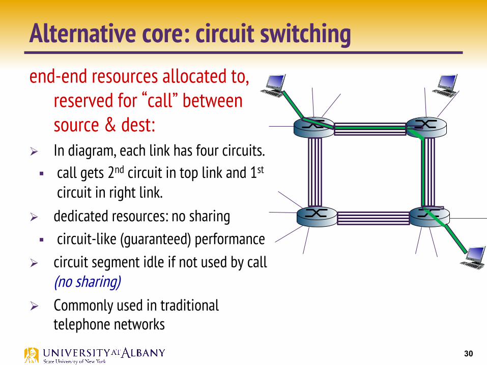
Alternative core: circuit switching
end-end resources allocated to, reserved for “call” between source & dest:
Ø In diagram, each link has four circuits. § call gets 2nd circuit in top link and 1st
circuit in right link. Ø dedicated resources: no sharing § circuit-like (guaranteed) performance
Ø circuit segment idle if not used by call (no sharing)
Ø Commonly used in traditional telephone networks

31
Circuit switching: FDM versus TDM
FDM
frequency
time TDM
frequency
time
4 users
Example:

32
Packet switching versus circuit switching
example: § 1 Mb/s link § each user:
• 100 kb/s when “active” • active 10% of time
circuit-switching: 10 users
packet switching: with 35 users, probability > 10 active
at same time is less than .0004 *
packet switching allows more users to use network!
N users
1 Mbps link
Q: how did we get value 0.0004?
Q: what happens if > 35 users ?
…..

33
great for bursty data resource sharing simpler, no call setup
excessive congestion possible: packet delay and loss protocols needed for reliable data transfer, congestion control Q: How to provide circuit-like behavior? bandwidth guarantees needed for audio/video apps still an unsolved problem
is packet switching a “slam dunk winner?”
Q: human analogies of reserved resources (circuit switching) versus on-demand allocation (packet-switching)?
Packet switching versus circuit switching

34
Internet structure: network of networks
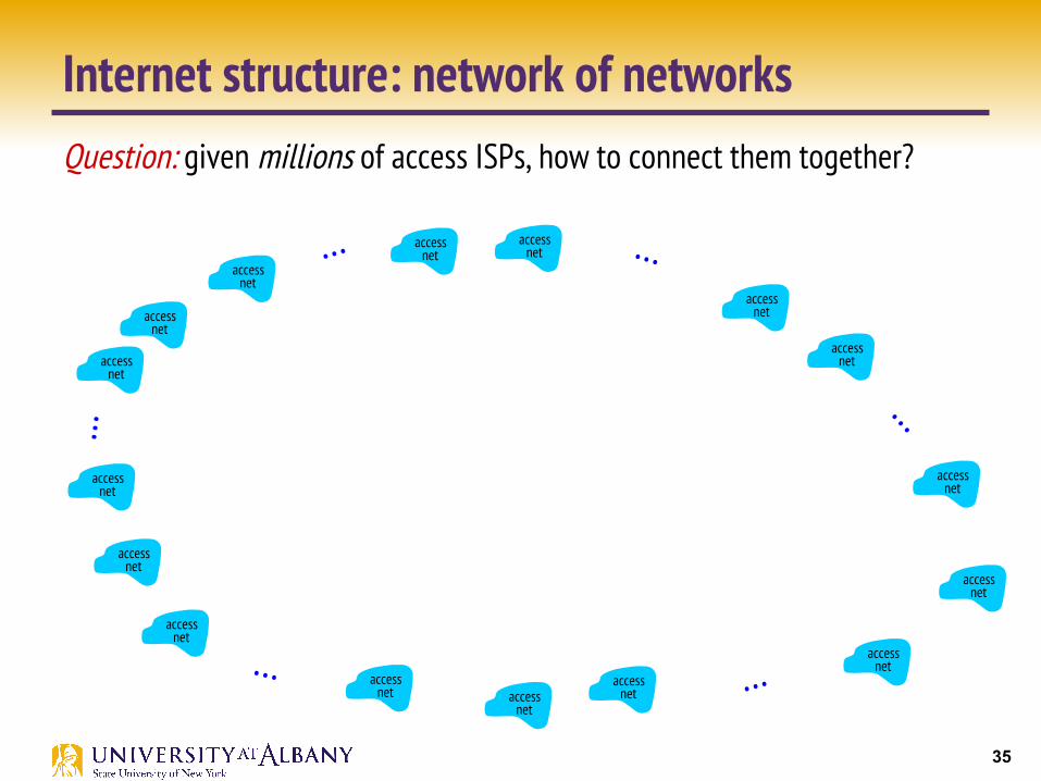
Ø End systems connect to Internet via access ISPs (Internet Service Providers) § Residential, company and university ISPs
Ø Access ISPs in turn must be interconnected. § So that any two hosts can send packets to each other
Ø Resulting network of networks is very complex § Evolution was driven by economics and national policies
Ø Let’s take a stepwise approach to describe current Internet structure
35
Internet structure: network of networks Question: given millions of access ISPs, how to connect them together?
access net
access net
access net
access net
access net
access net
access net
access net
access net
access net
access net
access net
access net
access net access
net
access net
…
… … …
…

36
Internet structure: network of networks Option: connect each access ISP to every other access ISP?
access net
access net
access net
access net
access net
access net
access net
access net
access net
access net
access net
access net
access net
access net access
net
access net
…
… … …
…
…
…
connecting each access ISP to each other directly doesn’t scale: O(N2)
connections.

37
Internet structure: network of networks
access net
access net
access net
access net
access net
access net
access net
access net
access net
access net
access net
access net
access net
access net access
net
access net
…
… … …
…
Option: connect each access ISP to a global transit ISP? Customer and provider ISPs have economic agreement.
global ISP

38
Internet structure: network of networks
access net
access net
access net
access net
access net
access net
access net
access net
access net
access net
access net
access net
access net
access net access
net
access net
…
… … …
…
But if one global ISP is viable business, there will be competitors ….
ISP B
ISP A
ISP C

39
Internet structure: network of networks
access net
access net
access net
access net
access net
access net
access net
access net
access net
access net
access net
access net
access net
access net access
net
access net
…
… … …
…
But if one global ISP is viable business, there will be competitors …. which must be interconnected
ISP B
ISP A
ISP C
IXP
IXP
peering link
Internet exchange point

40
Internet structure: network of networks
access net
access net
access net
access net
access net
access net
access net
access net
access net
access net
access net
access net
access net
access net access
net
access net
…
… … …
…
… and regional networks may arise to connect access nets to ISPS
ISP B
ISP A
ISP C
IXP
IXP
regional net

41
Internet structure: network of networks
access net
access net
access net
access net
access net
access net
access net
access net
access net
access net
access net
access net
access net
access net access
net
access net
…
… … …
…
… and content provider networks (e.g., Google, Microsoft, Akamai ) may run their own network, to bring services, content close to end users
ISP B
ISP A
ISP B
IXP
IXP
regional net
Content provider network

42
Internet structure: network of networks
Ø at center: small # of well-connected large networks § “tier-1” commercial ISPs (e.g., Level 3, Sprint, AT&T, NTT), national & international coverage § content provider network (e.g, Google): private network that connects it data centers to
Internet, often bypassing tier-1, regional ISPs
access ISP
access ISP
access ISP
access ISP
access ISP
access ISP
access ISP
access ISP
Regional ISP Regional ISP
IXP IXP
Tier 1 ISP Tier 1 ISP Google
IXP

43
Tier-1 ISP: e.g., Sprint
…
to/from customers
peering
to/from backbone
…
……
…
POP: point-of-presence

44
Support for Common Services Ø Logical Channels § Application-to-Application communication path or a pipe
Process communicating over an abstract channel

45
Common Communication Patterns
Ø Client/Server Ø Two types of communication channel § Request/Reply Channels § Message Stream Channels
46
Reliability
Ø Network should hide the errors Ø Bits are lost § Bit errors (1 to a 0, and vice versa) § Burst errors – several consecutive errors
Ø Packets are lost (Congestion) Ø Links and Node failures Ø Messages are delayed Ø Messages are delivered out-of-order Ø Third parties eavesdrop

47
Network Architecture
Example of a layered network system

48
Network Architecture
Layered system with alternative abstractions available at a given layer

49
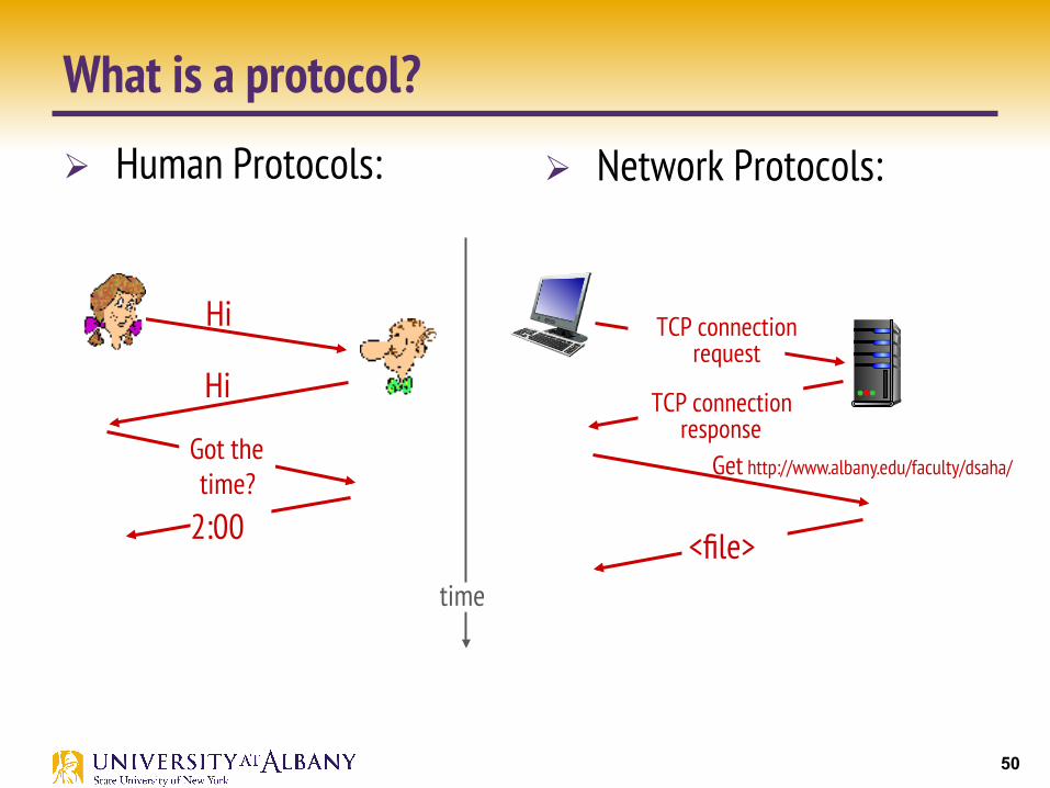
What is a protocol?
Ø Human Protocols: § What’s the time? § I have a question…. § Hi, I am XYZ…. § Hello, how are you?
Ø Network Protocols: § Nodes / machines in the
network participate § Communication activity in
Internet is governed by Network Protocols
§ Are you alive? § Do you know the route to node
X?
Protocols define format, order of messages sent and received among network entities, and actions taken on message transmission, receipt
50
What is a protocol?
Ø Human Protocols: Ø Network Protocols:
Hi
Hi
Got the time?
2:00
TCP connection response
Get http://www.albany.edu/faculty/dsaha/
<file> time
TCP connection request

51
Protocols
Ø Protocol defines the interfaces between the layers in the same system and with the layers of peer system
Ø Building blocks of a network architecture Ø Each protocol object has two different interfaces § service interface: operations on this protocol § peer-to-peer interface: messages exchanged with peer
Ø Term “protocol” is overloaded § specification of peer-to-peer interface § module that implements this interface

52
Interfaces
Service and Peer Interfaces

53
Protocols
Ø Protocol Specification: prose, pseudo-code, state transition diagram
Ø Interoperable: when two or more protocols that implement the specification accurately
Ø IETF: Internet Engineering Task Force

54
Protocol Graph
Example of a protocol graph nodes are the protocols and links the “depends-on” relation

55
Protocol Layers
Ø Networks are complex, with many “pieces”: § hosts § routers § links of various media § applications § protocols § hardware, software
Question: is there any hope of organizing structure of network?

56
Organization of air travel
ticket (purchase) baggage (check) gates (load) runway takeoff airplane routing
ticket (complain) baggage (claim) gates (unload) runway landing airplane routing
airplane routing

57
Layering of airline functionality
ticket (purchase)
baggage (check)
gates (load)
runway (takeoff)
airplane routing
departure airport
arrival airport
intermediate air-traffic control centers
airplane routing airplane routing
ticket (complain)
baggage (claim
gates (unload)
runway (land)
airplane routing
ticket
baggage
gate
takeoff/landing
airplane routing
Ø layers: each layer implements a service § via its own internal-layer actions § relying on services provided by layer below

58
Why layering?
Ø dealing with complex systems: § explicit structure allows identification, relationship of complex
system’s pieces o layered reference model for discussion
Ø modularization eases maintenance, updating of system § change of implementation of layer’s service transparent to rest of
system § e.g., change in gate procedure doesn’t affect rest of system
Ø layering considered harmful?

59
OSI Architecture The OSI 7-layer Model
OSI – Open Systems Interconnection

60
Description of Layers
Ø Physical Layer § Handles the transmission of raw bits over a communication link
Ø Data Link Layer § Collects a stream of bits into a larger aggregate called a frame § Network adaptor along with device driver in OS implement the
protocol in this layer § Frames are actually delivered to hosts
Ø Network Layer § Handles routing among nodes within a packet-switched network § Unit of data exchanged between nodes in this layer is called a packet
The lower three layers are implemented on all network nodes

61
Description of Layers Ø Transport Layer § Implements a process-to-process channel § Unit of data exchanges in this layer is called a message
Ø Session Layer § Provides a name space that is used to tie together the potentially different transport
streams that are part of a single application
Ø Presentation Layer § Concerned about the format of data exchanged between peers
Ø Application Layer § Standardize common type of exchanges
The transport layer and the higher layers typically run only on end-hosts and not on the intermediate switches and routers

62
Internet Protocol Stack
Ø application: supporting network applications § FTP, SMTP, HTTP
Ø transport: process-process data transfer § TCP, UDP
Ø network: routing of datagrams from source to destination
§ IP, routing protocols
Ø link: data transfer between neighboring network elements
§ Ethernet, 802.11 (WiFi)
Ø physical: bits “on the wire” / “over the air”
application
transport
network
link
physical

63
High-level messages are encapsulated inside of low-level messages
Encapsulation

64
Encapsulation
source
application transport network
link physical
Ht Hn M
segment Ht
datagram
destination
application transport network
link physical
Ht Hn Hl M
Ht Hn M
Ht M
M network
link physical
link physical
Ht Hn Hl M
Ht Hn M
Ht Hn M
Ht Hn Hl M
router
switch
message M
Ht M
Hn
frame

65
Internet Architecture
Internet Protocol Graph
Alternative view of the Internet architecture. The “Network” layer shown here is sometimes referred to as the “sub-network” or “link” layer.

66
Internet Architecture Ø Defined by IETF (The Internet Engineering Task Force)
Ø Three main features § Does not imply strict layering. The application is free to bypass the
defined transport layers and to directly use IP or other underlying networks
§ An hour-glass shape – wide at the top, narrow in the middle and wide at the bottom. IP serves as the focal point for the architecture
§ In order for a new protocol to be officially included in the architecture, there needs to be both a protocol specification and at least one (and preferably two) representative implementations of the specification

67
Application Programming Interface Ø Interface exported by the network
Ø Since most network protocols are implemented (those in the high protocol stack) in software and nearly all computer systems implement their network protocols as part of the operating system, when we refer to the interface “exported by the network”, we are generally referring to the interface that the OS provides to its networking subsystem
Ø The interface is called the network Application Programming Interface (API)

68
Application Programming Interface (Sockets)
Ø Socket Interface was originally provided by the Berkeley distribution of Unix
§ Now supported in virtually all operating systems
Ø Each protocol provides a certain set of services, and the API provides a syntax by which those services can be invoked in this particular OS

69
Socket Ø What is a socket? § The point where a local application process attaches to the
network § An interface between an application and the network § An application creates the socket
Ø The interface defines operations for § Creating a socket § Attaching a socket to the network § Sending and receiving messages through the socket § Closing the socket
70
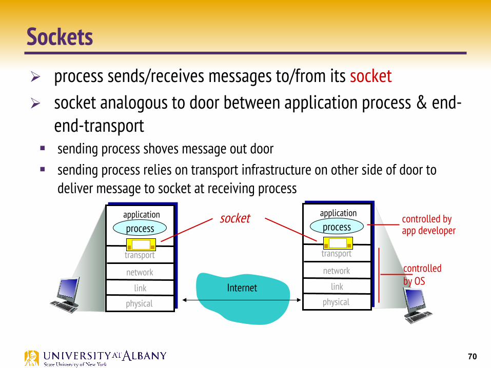
Ø process sends/receives messages to/from its socket Ø socket analogous to door between application process & end-
end-transport § sending process shoves message out door § sending process relies on transport infrastructure on other side of door to
deliver message to socket at receiving process
Sockets
Internet
controlled by OS
controlled by app developer
transport
application
physical
link
network
process
transport
application
physical
link
network
process socket
71
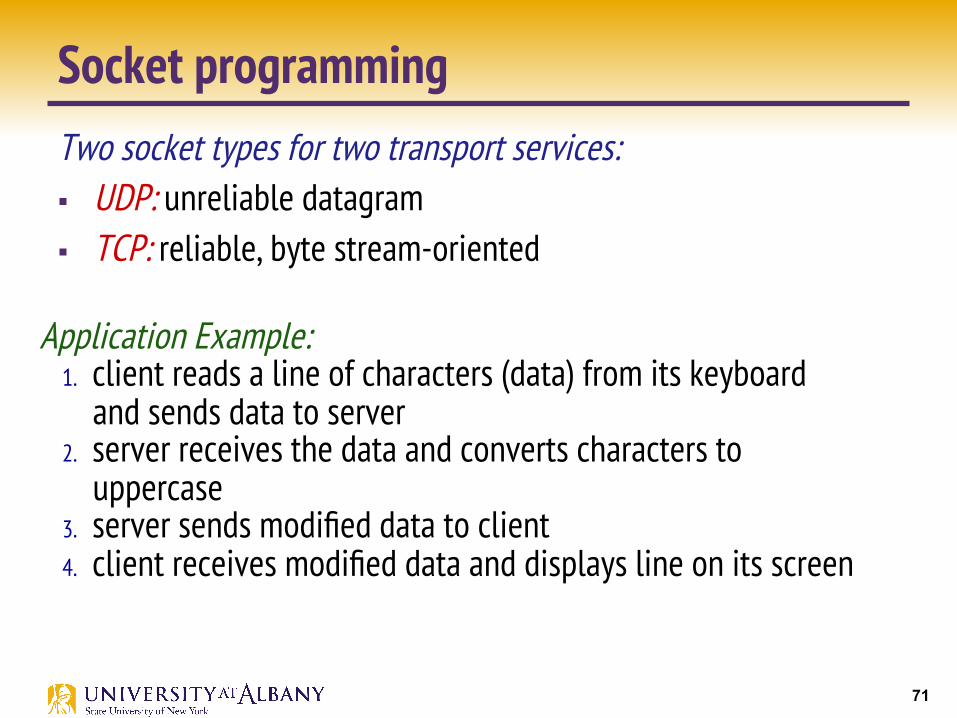
Socket programming Two socket types for two transport services: § UDP: unreliable datagram § TCP: reliable, byte stream-oriented
Application Example: 1. client reads a line of characters (data) from its keyboard
and sends data to server 2. server receives the data and converts characters to
uppercase 3. server sends modified data to client 4. client receives modified data and displays line on its screen
72
Socket programming with UDP
UDP: no “connection” between client & server Ø no handshaking before sending data Ø sender explicitly attaches IP destination address and port # to each
packet Ø receiver extracts sender IP address and port# from received packet
UDP: transmitted data may be lost or received out-of-order
Application viewpoint: Ø UDP provides unreliable transfer of groups of bytes (“datagrams”)
between client and server

73
Client/server socket interaction: UDP
close clientSocket
read datagram from clientSocket
create socket: clientSocket = socket(AF_INET,SOCK_DGRAM)
Create datagram with server IP and port=x; send datagram via clientSocket
create socket, port= x: serverSocket = socket(AF_INET,SOCK_DGRAM)
read datagram from serverSocket
write reply to serverSocket specifying client address, port number
server (running on serverIP) client

74
Example app: UDP client
from socket import * serverName = ‘hostname’ serverPort = 12000 clientSocket = socket(AF_INET, SOCK_DGRAM) message = raw_input(’Input lowercase sentence:’) clientSocket.sendto(message.encode(),
(serverName, serverPort))
modifiedMessage, serverAddress = clientSocket.recvfrom(2048) print modifiedMessage.decode() clientSocket.close()
Python UDPClient include Python’s socket library
create UDP socket for server
get user keyboard input
Attach server name, port to message; send into socket
print out received string and close socket
read reply characters from socket into string

75
Example app: UDP server
from socket import * serverPort = 12000 serverSocket = socket(AF_INET, SOCK_DGRAM) serverSocket.bind(('', serverPort)) print (“The server is ready to receive”) while True: message, clientAddress = serverSocket.recvfrom(2048) modifiedMessage = message.decode().upper() serverSocket.sendto(modifiedMessage.encode(), clientAddress)
Python UDPServer
create UDP socket
bind socket to local port number 12000
loop forever
Read from UDP socket into message, getting client’s address (client IP and port)
send upper case string back to this client

76
Socket programming with TCP client must contact server Ø server process must first be
running Ø server must have created socket
(door) that welcomes client’s contact
client contacts server by: Ø Creating TCP socket, specifying IP
address, port number of server process
Ø when client creates socket: client TCP establishes connection to server TCP
Ø when contacted by client, server TCP creates new socket for server process to communicate with that particular client
§ allows server to talk with multiple clients
§ source port numbers used to distinguish clients (more in Chap 3)
TCP provides reliable, in-order byte-stream transfer (“pipe”) between client and server
application viewpoint:

77
Client/server socket interaction: TCP
wait for incoming connection request connectionSocket = serverSocket.accept()
create socket, port=x, for incoming request: serverSocket = socket()
create socket, connect to hostid, port=x clientSocket = socket()
server (running on hostid) client
send request using clientSocket read request from
connectionSocket write reply to connectionSocket
TCP connection setup
close connectionSocket
read reply from clientSocket close clientSocket

78
Example app: TCP client
from socket import * serverName = ’servername’ serverPort = 12000 clientSocket = socket(AF_INET, SOCK_STREAM) clientSocket.connect((serverName,serverPort)) sentence = raw_input(‘Input lowercase sentence:’) clientSocket.send(sentence.encode()) modifiedSentence = clientSocket.recv(1024) print (‘From Server:’, modifiedSentence.decode()) clientSocket.close()
Python TCPClient
create TCP socket for server, remote port 12000
No need to attach server name, port

79
Example app: TCP server
from socket import * serverPort = 12000 serverSocket = socket(AF_INET,SOCK_STREAM) serverSocket.bind((‘’,serverPort)) serverSocket.listen(1) print ‘The server is ready to receive’ while True: connectionSocket, addr = serverSocket.accept() sentence = connectionSocket.recv(1024).decode() capitalizedSentence = sentence.upper() connectionSocket.send(capitalizedSentence. encode()) connectionSocket.close()
Python TCPServer
create TCP welcoming socket
server begins listening for incoming TCP requests
loop forever
server waits on accept() for incoming requests, new socket created on return
read bytes from socket (but not address as in UDP)
close connection to this client (but not welcoming socket)

80
Port Numbers Ø Commonly used: § 21: File Transfer Protocol (FTP) § 22: Secure Shell (SSH) § 23: Telnet remote login service § 25: Simple Mail Transfer Protocol (SMTP) § 80: Hypertext Transfer Protocol (HTTP) used in the World Wide Web § 110: Post Office Protocol (POP3) § 123: Network Time Protocol (NTP) § 143: Internet Message Access Protocol (IMAP) § 443: HTTP Secure (HTTPS)
Ø The registered ports are those from 1024 through 49151. IANA maintains the official list of registered ports.
Ø The dynamic or private ports are those from 49152 through 65535.

81
Performance Ø Bandwidth § Width of the frequency band § Number of bits per second that can be transmitted over a
communication link
Ø 1 Mbps: 1 x 106 bits/second = 1x220 bits/sec Ø 1 x 10⁻⁶ seconds to transmit each bit or imagine that a
timeline, now each bit occupies 1 micro second space. Ø On a 2 Mbps link the width is 0.5 micro second. Ø Smaller the width more will be transmission per unit time.

82
Bandwidth
Bits transmitted at a particular bandwidth can be regarded as having some width: (a) bits transmitted at 1Mbps (each bit 1 µs wide); (b) bits transmitted at 2Mbps (each bit 0.5 µs wide).

83
How do loss and delay occur? packets queue in router buffers Ø packet arrival rate to link (temporarily) exceeds output link capacity Ø packets queue, wait for turn
A
B
packet being transmitted (delay)
packets queueing (delay)
free (available) buffers: arriving packets dropped (loss) if no free buffers

84
Four sources of packet delay
dproc: nodal processing § check bit errors § determine output link § typically < msec
A
B
propagation
transmission
nodal processing queueing
dqueue: queueing delay § time waiting at output link for
transmission § depends on congestion level of
router
dnodal = dproc + dqueue + dtrans + dprop

85
Four Sources of Packet Delay
dtrans: transmission delay: § L: packet length (bits) § R: link bandwidth (bps) § dtrans = L/R
dprop: propagation delay: § d: length of physical link § s: propagation speed in medium (~2x10⁸
m/sec) § dprop = d/s dtrans and dprop
very different
propagation
nodal processing queueing
dnodal = dproc + dqueue + dtrans + dprop
A
B
transmission

86
Caravan analogy
Ø cars “propagate” at 100 km/hr
Ø toll booth takes 12 sec to service car (bit transmission time)
Ø car~bit; caravan ~ packet Ø Q: How long until caravan is
lined up before 2nd toll booth?
Ø time to “push” entire caravan through toll booth onto highway = 12*10 = 120 sec
Ø time for last car to propagate from 1st to 2nd toll both: 100km/(100km/hr)= 1 hr
Ø A: 62 minutes
toll booth
toll booth
ten-car caravan
100 km 100 km

87
Caravan analogy (more)
Ø suppose cars now “propagate” at 1000 km/hr Ø and suppose toll booth now takes one min to service a car Ø Q: Will cars arrive to 2nd booth before all cars serviced at first booth?
Ø A: Yes! after 7 min, 1st car arrives at second booth; three cars still at 1st booth.
toll booth
toll booth
ten-car caravan
100 km 100 km

88
Queueing delay (revisited) Ø R: link bandwidth (bps) Ø L: packet length (bits) Ø a: average packet arrival rate
traffic intensity = La/R v La/R ~ 0: avg. queueing delay small
v La/R -> 1: avg. queueing delay large v La/R > 1: more “work” arriving than can be serviced, average delay infinite!
aver
age
que
uein
g de
lay
La/R ~ 0 La/R -> 1

89
“Real” Internet delays and routes Ø what do “real” Internet delay & loss look like? Ø traceroute program: provides delay measurement from
source to router along end-end Internet path towards destination. For all i:
§ sends three packets that will reach router i on path towards destination § router i will return packets to sender § sender times interval between transmission and reply.
3 probes
3 probes
3 probes

90
Real Internet Delays, routes traceroute to openairinterface.org
trans-oceanic link
3 delay measurements
* means no response (probe lost, router not replying)
From UAlbany
From Home

91
Packet loss
Ø queue (aka buffer) preceding link in buffer has finite capacity
Ø packet arriving to full queue dropped (aka lost) Ø lost packet may be retransmitted by previous node, by
source end system, or not at all
A
B
packet being transmitted
packet arriving to full buffer is lost
buffer (waiting area)

92
Throughput
Ø throughput: rate (bits/time unit) at which bits transferred between sender/receiver
§ instantaneous: rate at given point in time § average: rate over longer period of time
server, with file of F bits
to send to client
link capacity Rs bits/sec
link capacity Rc bits/sec
server sends bits (fluid) into pipe
pipe that can carry fluid at rate Rs bits/sec)
pipe that can carry fluid at rate Rc bits/sec)

93
Throughput (more)
Ø Rs < Rc What is average end-end throughput?
Rs bits/sec Rc bits/sec
v Rs > Rc What is average end-end throughput?
link on end-end path that constrains end-end throughput bottleneck link
Rs bits/sec Rc bits/sec

94
Throughput: Internet scenario Ø per-connection end-end
throughput: min(Rc,Rs,R/10)
Ø in practice: Rc or Rs is often bottleneck
10 connections (fairly) share backbone bottleneck link R bits/sec
Rs
Rs
Rs
Rc
Rc
Rc
R

95
Performance Ø Latency = Propagation + processing + transmit + queue Ø Propagation = distance/speed of light Ø Transmit = size/bandwidth Ø Processing = depends on the node (hardware + software)
Ø One bit transmission => propagation is important Ø Large bytes transmission => bandwidth is important
96
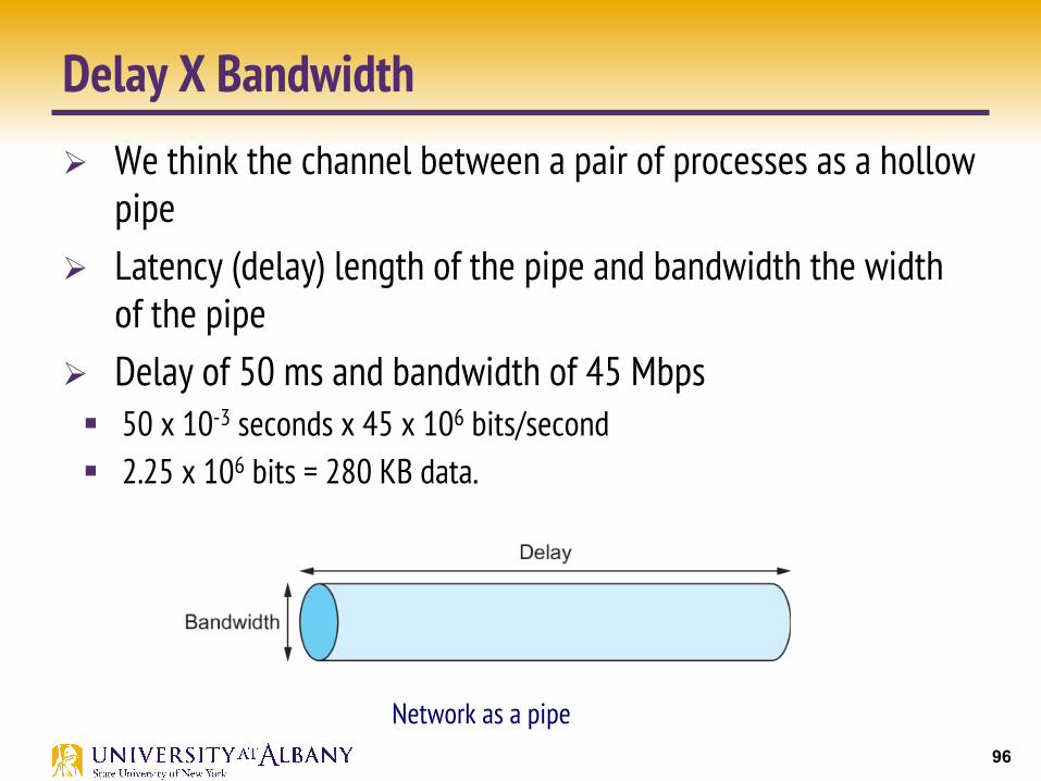
Delay X Bandwidth Ø We think the channel between a pair of processes as a hollow
pipe Ø Latency (delay) length of the pipe and bandwidth the width
of the pipe Ø Delay of 50 ms and bandwidth of 45 Mbps § 50 x 10-3 seconds x 45 x 106 bits/second § 2.25 x 106 bits = 280 KB data.
Network as a pipe

97
Delay X Bandwidth Ø Relative importance of bandwidth and latency depends on
application § For large file transfer, bandwidth is critical § For small messages (HTTP, NFS, etc.), latency is critical § Variance in latency (jitter) can also affect some applications (e.g.,
audio/video conferencing)

98
Delay X Bandwidth
Ø How many bits the sender must transmit before the first bit arrives at the receiver if the sender keeps the pipe full
Ø Takes another one-way latency to receive a response from the receiver
Ø If the sender does not fill the pipe—send a whole delay × bandwidth product’s worth of data before it stops to wait for a signal—the sender will not fully utilize the network

99
Delay X Bandwidth
Ø Infinite bandwidth § RTT dominates § Throughput = TransferSize / TransferTime § TransferTime = RTT + 1/Bandwidth x TransferSize
Ø Its all relative § 1-MB file to 1-Gbps link looks like a 1-KB packet to 1-Mbps link

100
Relationship between bandwidth and latency
A 1-MB file would fill the 1-Mbps link 80 times, but only fill the 1-Gbps link 1/12 of one time
101
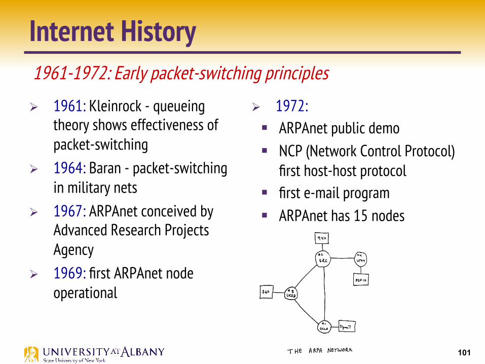
Internet History
Ø 1961: Kleinrock - queueing theory shows effectiveness of packet-switching
Ø 1964: Baran - packet-switching in military nets
Ø 1967: ARPAnet conceived by Advanced Research Projects Agency
Ø 1969: first ARPAnet node operational
Ø 1972: § ARPAnet public demo § NCP (Network Control Protocol)
first host-host protocol § first e-mail program § ARPAnet has 15 nodes
Introduction
1961-1972: Early packet-switching principles

102
Ø 1970: ALOHAnet satellite network in Hawaii
Ø 1974: Cerf and Kahn - architecture for interconnecting networks
Ø 1976: Ethernet at Xerox PARC Ø late70’s: proprietary
architectures: DECnet, SNA, XNA Ø late 70’s: switching fixed length
packets (ATM precursor) Ø 1979: ARPAnet has 200 nodes
Introduction
1972-1980: Internetworking, new and proprietary nets Internet History
Cerf and Kahn’s internetworking principles:
minimalism, autonomy - no internal changes required to interconnect networks best effort service model stateless routers decentralized control
define today’s Internet architecture

103
Ø 1983: deployment of TCP/IP
Ø 1982: smtp e-mail protocol defined
Ø 1983: DNS defined for name-to-IP-address translation
Ø 1985: ftp protocol defined Ø 1988: TCP congestion
control
Internet History
Ø new national networks: Csnet, BITnet, NSFnet, Minitel
Ø 100,000 hosts connected to confederation of networks
1980-1990: new protocols, a proliferation of networks

104
Ø early 1990’s: ARPAnet decommissioned
Ø 1991: NSF lifts restrictions on commercial use of NSFnet (decommissioned, 1995)
Ø early 1990s: Web § hypertext [Bush 1945, Nelson
1960’s] § HTML, HTTP: Berners-Lee § 1994: Mosaic, later Netscape § late 1990’s:
commercialization of the Web
late 1990’s – 2000’s: Ø more killer apps: instant
messaging, P2P file sharing Ø network security to forefront Ø est. 50 million host, 100
million+ users Ø backbone links running at Gbps
Introduction
1990, 2000’s: commercialization, the Web, new apps
Internet History

105
2005-present Ø ~750 million hosts § Smartphones and tablets
Ø Aggressive deployment of broadband access Ø Increasing ubiquity of high-speed wireless access Ø Emergence of online social networks: § Facebook: 1.71 billion active users
Ø Service providers (Google, Microsoft) create their own networks § Bypass Internet, providing “instantaneous” access to search, email,
etc. Ø E-commerce, universities, enterprises running their services in
“cloud” (eg, Amazon EC2)
Internet History

106
Summary Ø We have identified what we expect from a computer network
Ø We have defined a layered architecture for computer network that will serve as a blueprint for our design
Ø We have discussed the socket interface which will be used by applications for invoking the services of the network subsystem
Ø We have discussed two performance metrics using which we can analyze the performance of computer networks

107
Chapter 1, Problem 4 Ø Calculate the total time required to transfer a 1.5MB file in
following cases with assumptions a) RTT is 80ms, b) packet size is 1KB, c) initial 2xRTT is required for handshaking before transmission:
§ Bandwidth is 10Mbps and data packets can be sent continuously
§ Convert everything in same unit o 1.5MB = 1.5x1024KB = 1.5x1024x1024x8 bits = 12582912bits o 10Mbps = 10000000bps
§ Total Time = initial 2RTT + Transmit Delay + Propagation Delay (RTT/2) o 80x2/1000 + 12582912/10000000 + 40/1000 secs o 1.458 secs

108
Chapter 1, Problem 4 Ø Calculate the total time required to transfer a 1.5MB file in
following cases with assumptions a) RTT is 80ms, b) packet size is 1KB, c) initial 2xRTT is required for handshaking before transmission:
§ Bandwidth is 10Mbps, but wait for one RTT between packets
§ Number of packets o 1.5MB / 1KB = 1.5x1024 = 1536
§ 1535 interpacket gaps between 1536 packets § Add 1535xRTT to previous solution o 1535x80/1000secs + 1.458secs o 124.258 secs

109
Chapter 1, Problem 4 Ø Calculate the total time required to transfer a 1.5MB file in
following cases with assumptions a) RTT is 80ms, b) packet size is 1KB, c) initial 2xRTT is required for handshaking before transmission:
§ Link allows infinitely fast transmit, but limits bandwidth – 20 packets can be sent in one RTT
§ Transmit Time = 0 § 1536 packets / 20 = 76.8 batches (76 full batch and 1 partial batch) § Propagation delay for the first batch = RTT/2 § Initial Setup = RTTx2 § 76 batches in 76xRTT time § Total = 80x2/1000 + 40/1000 + 76x80/1000 secs = 6.28 secs
110
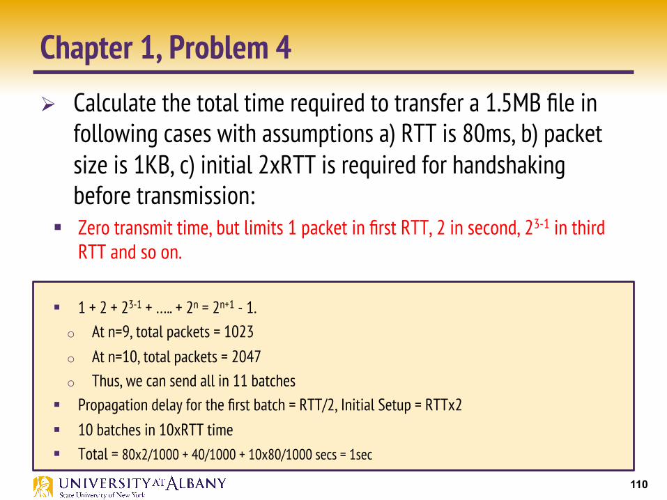
Chapter 1, Problem 4 Ø Calculate the total time required to transfer a 1.5MB file in
following cases with assumptions a) RTT is 80ms, b) packet size is 1KB, c) initial 2xRTT is required for handshaking before transmission:
§ Zero transmit time, but limits 1 packet in first RTT, 2 in second, 23-1 in third RTT and so on.
§ 1 + 2 + 23-1 + ….. + 2n = 2n+1 - 1. o At n=9, total packets = 1023 o At n=10, total packets = 2047 o Thus, we can send all in 11 batches
§ Propagation delay for the first batch = RTT/2, Initial Setup = RTTx2 § 10 batches in 10xRTT time § Total = 80x2/1000 + 40/1000 + 10x80/1000 secs = 1sec