Embed Size (px)
Citation preview

Subject: Computer Fundamentals Author: Dr. Pradeep Bhatia Paper Code: MCA 101 Vetter: Prof. Dharminder Kumar Lesson: Computer Basics Lesson No. : 01 Structure 1.0 Objective 1.1Introduction 1.2 Usage of Computer 1.3 Anatomy of a Digital Computer 1.4 Human-Being Vs Computer 1.5 Representation of Information inside a Computer 1.6 Integer representation 1.7 Fixed point and Floating point representation 1.8 Radix Number System 1.9 Conversions between Number Bases 1.10 Summary 1.11 Self Assessment Questions

1.0 Objective Objective of this lesson get acquaint the reader to the basic units of a computer system; learn about the digit symbols, base, and representation of various number systems, methods of number system conversions; understand with the coding schemes for the internal storage of characters. 1.1 Introduction Computer is an electronic device, which accepts data, processes it and outputs the results in the form of reports. Original objective of computer was to make fast calculations, but the modern computers besides performing fast calculations can store large volume of data, process and retrieve data as and when desired. Hence computers are also known as data processors. Computer is a system. A system is a group of integrated parts to achieve a common objective. Computer is made up of integrated parts (input, control, ALU, storage and output unit) .All the parts work together to process data. The computer accepts input and outputs data in an alphanumeric form. Internally it converts the input data to meaning binary digits, performs the instructed operations on the binary data, and transforms the data from binary digit form to understandable alphanumeric form. 1.2 Usage of Computers in Everyday life Computers have a significant impact on everyday life in nearly all areas.
Computers are used in:
Airline and Railway Reservations
Medical Diagnosis
Whether Forecasting
Payment of telephone and electricity bills
Banking
Space research
Online Education
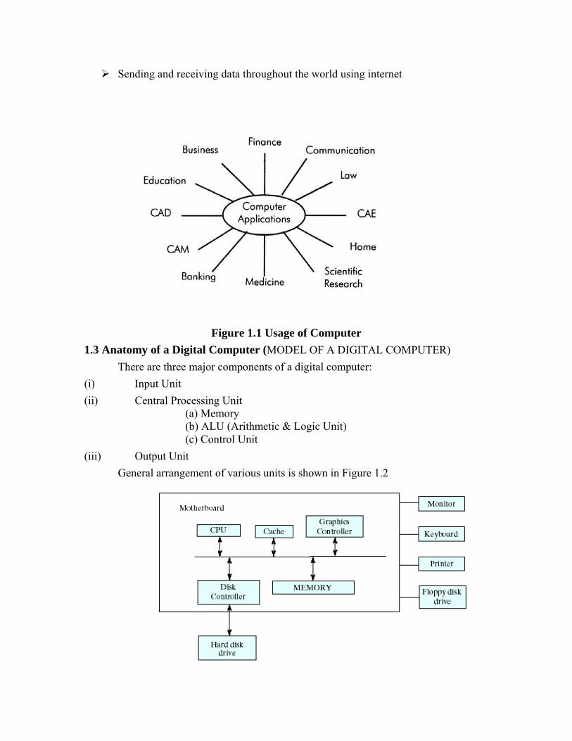
Sending and receiving data throughout the world using internet
Figure 1.1 Usage of Computer 1.3 Anatomy of a Digital Computer (MODEL OF A DIGITAL COMPUTER)
There are three major components of a digital computer: (i) Input Unit (ii) Central Processing Unit
(a) Memory (b) ALU (Arithmetic & Logic Unit) (c) Control Unit
(iii) Output Unit General arrangement of various units is shown in Figure 1.2
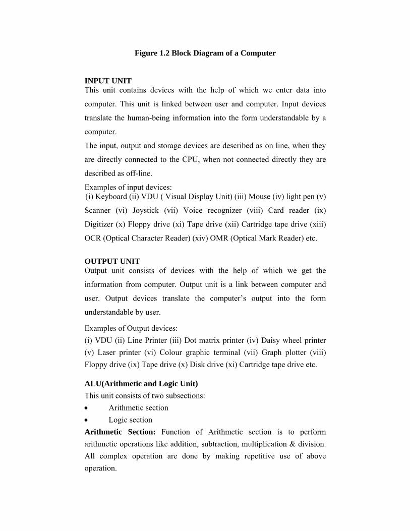
Figure 1.2 Block Diagram of a Computer INPUT UNIT This unit contains devices with the help of which we enter data into
computer. This unit is linked between user and computer. Input devices
translate the human-being information into the form understandable by a
computer.
The input, output and storage devices are described as on line, when they
are directly connected to the CPU, when not connected directly they are
described as off-line.
Examples of input devices: {i) Keyboard (ii) VDU ( Visual Display Unit) (iii) Mouse (iv) light pen (v)
Scanner (vi) Joystick (vii) Voice recognizer (viii) Card reader (ix)
Digitizer (x) Floppy drive (xi) Tape drive (xii) Cartridge tape drive (xiii)
OCR (Optical Character Reader) (xiv) OMR (Optical Mark Reader) etc.
OUTPUT UNIT Output unit consists of devices with the help of which we get the
information from computer. Output unit is a link between computer and
user. Output devices translate the computer’s output into the form
understandable by user.
Examples of Output devices: (i) VDU (ii) Line Printer (iii) Dot matrix printer (iv) Daisy wheel printer (v) Laser printer (vi) Colour graphic terminal (vii) Graph plotter (viii) Floppy drive (ix) Tape drive (x) Disk drive (xi) Cartridge tape drive etc. ALU(Arithmetic and Logic Unit) This unit consists of two subsections: • Arithmetic section • Logic section Arithmetic Section: Function of Arithmetic section is to perform arithmetic operations like addition, subtraction, multiplication & division. All complex operation are done by making repetitive use of above operation.
Logic Section: Function of logic section is to perform logic operations such as comparing, selecting, matching and merging of data.
The arithmetic and logic unit (ALU) contains a number of storage
locations referred to as registers. These registers are composed of
electronic circuitry having the capability of adding, subtracting,
multiplying rounding off etc., the number of registers in a computer vary
from model to model. However, the basic registers in any computer are the
adder and the accumulator.
An interesting side limit is that a computer can only add. It can not carry
out subtraction, Multiplication and division operating in the way it is done
manually. For these operations, it also has to take the add route. Thus if 15
to be multiplied by 10, the computer adds the data item 15 times. For
subtraction and division, it employs the 1’s complement method, which
again is a form of the addition process. The basic add & subtract operation
have been carried out by the computer by means of dedicated circuits
called micropragrams.
CONTROL UNIT Control unit controls the operations of all parts of computers. It does not carry out any actual data processing operations. • It retrieves instructions from the main memory and determines what is
to be taken. • It then retrieves the data required to be processed from the main
memory. • It causes the CPU to actually carry out required operations and
determine whether the required operation have been carried out or not. • It places the processed results in the output area of the memory. • It fetches the next instruction from the memory and repeat the whole
cycle of operations outlined above. In addition to the above, the control unit also oversees that erroneous data
does not enter into the system (for example, numeric data consisting of
alphabets or a number is divided by zero). When such an event occurs, the
control unit displays an error on the screen of the CPU to warn computer
operator.
In order to carry out these operations, the control unit also has its own set
of registers (like those of ALU). The basic register of the control unit are
the instruction register, the decoder & the address register.
MEMORY OR STORAGE UNIT The function of storage unit is to store instruction, data and intermediate
results. This unit supplies information to the other units of the computer
when needed. It is also known as internal storage unit or main memory or
primary storage. Memory is part of the main computer system. The
processor access the main memory in direct fashion, that is, the processor
can access any location of this memory either to read information from it
or store information in it. The primary memory is implemented by two
types of memory technologies. The first is called random access memory
(RAM) an other is read only memory(ROM). Its size affects speed, power
and capabilities.
Random Access Memory
RAM directly provides the required information to the processor. It can be
defined as a block of sequential memory locations, each of which has a
unique address determining the location and those locations contain a data
element. Storage locations in main memory are addressed directly by the
CPU’s instructions. It is volatile in nature, as soon as powered turned off,
the information stored in it will lost. RAM can be further divided into two
categories:
• Dynamic Random Access Memory
• Static Random Access Memory
Dynamic Random Access Memory(DRAM):
This type of memory holds the data in dynamic manner with the help of a
refresh circuitry. Each second or even less that contents of each memory
cell is read and the reading action refreshing the contents of the memory.
Due to refreshing action, this memory is called dynamic RAM.
Static Random Access Memory (SRAM):
SRAM along with DRAM is essential for a system to run optimally,
because it is very fast as compared to DRAM. It is effective because most
programs access the same data repeatedly and keeping all this information
in the first written to SRAM assuming that it will be used again soon.
SRAM is generally included in computer system by the name of cache.
Read Only Memory (ROM) As the name suggests, read only memory can only be read, not written.
CPU can only read from any location in the ROM but cannot write. The
contents of ROM are not lost even in case of a sudden power failure,
making it non-volatile in nature. The instructions in ROM are built into
the electronic circuit of the chip. These instructions are called firmware.
Read only memory is also random access in nature, which means that
CPU can randomly access any location within ROM. Improvement in
technology for construction flexible ROM has brought,
PROM(Programmable Read Only Memory), EPROM(Erasable
Programmable Read Only Memory), and EEPROM(Electrical Erasable
Read Only Memory) into existence.
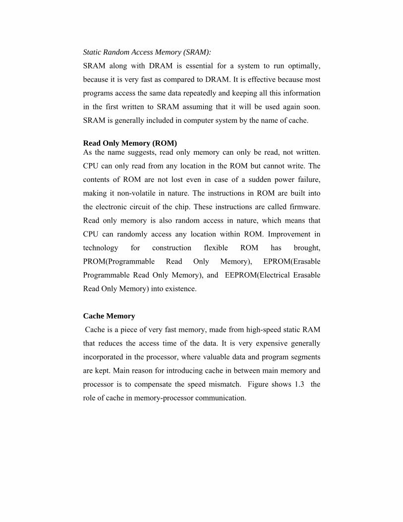
Cache Memory
Cache is a piece of very fast memory, made from high-speed static RAM
that reduces the access time of the data. It is very expensive generally
incorporated in the processor, where valuable data and program segments
are kept. Main reason for introducing cache in between main memory and
processor is to compensate the speed mismatch. Figure shows 1.3 the
role of cache in memory-processor communication.
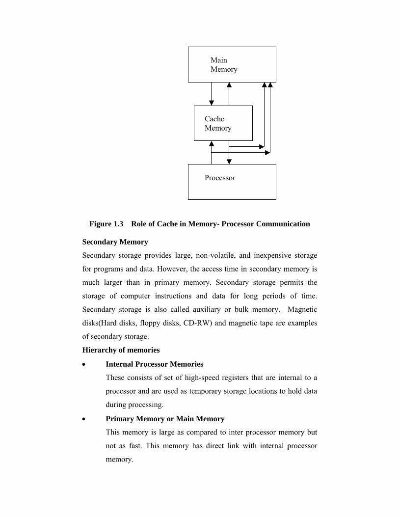
Figure 1.3 Role of Cache in Memory- Processor Communication Secondary Memory
Secondary storage provides large, non-volatile, and inexpensive storage
for programs and data. However, the access time in secondary memory is
much larger than in primary memory. Secondary storage permits the
storage of computer instructions and data for long periods of time.
Secondary storage is also called auxiliary or bulk memory. Magnetic
disks(Hard disks, floppy disks, CD-RW) and magnetic tape are examples
of secondary storage.
Hierarchy of memories
Main Memory
Cache Memory
Processor
• Internal Processor Memories
These consists of set of high-speed registers that are internal to a
processor and are used as temporary storage locations to hold data
during processing.
• Primary Memory or Main Memory
This memory is large as compared to inter processor memory but
not as fast. This memory has direct link with internal processor
memory.
• Secondary Memory or Auxiliary Memory
This memory is much large in size compared to main memory but is
slower.
There is another kind of memory used in modern computers. It is called
cache memory. Though it is a part of main memory, it is logically
positioned between the internal memory, registers, and main memory.
Figure 1.4 shows the hierarchy of memories.
Figure 1.4 The Memory hierarchy Unit of Memory The various units used to measure computer memory, are as follows:
Bit: Bit, Abbreviation for binary digit, is basic unit of memory. It is
smallest unit of information. Bit is represented by a lower case b.
Byte: A unit of 8 bits is known as a byte. Hence, a byte is able to contain
any binary number between 00000000 and 11111111. It is represented by
uppercase B.
Kilobyte: One KB is equal to 1024 bytes.
CPU Registers
Cache Memory
Main Memory
Secondary Memory
Megabyte: One MB is equal to 1024 KB.
Gigabyte: One GB is equal to 1024 MB.
Terabyte: One TB is equal to 1024 GB.
1.4 HUMAN-BEING VS COMPUTER People receive input data by seeing of hearing them. These data are then
stored in the brain, which also acts a control and logic unit. The outputs
form this type of information processing is oral or written reports and in
some cases a variety of physical actions. The human mind, acting as a
control and logic unit, can perform many operations on data: adding,
subtracting, multiplying, and dividing, storing result, repeating the
operations on different sets of data, comparing two items, outputting result
in a prearranged manner, and revising the processing as a result of
changed instruction.
The human mind is slow in performing the arithmetic computations
required and is rather erratic in applying rules of logic. On the other hand,
where judgement is required, the human mind is indispensable. Judgement
is needed to make decisions in data processing systems because of the
difficulty of planning to handle all eventualities. In summary, human
being alone are inefficient data processors, but they become a vital
element of all data processing system because of the need for decision and
judgement. Similarities and differences of a computer system with human
being is given in Table 1.1 and Table 1.2 respectively.
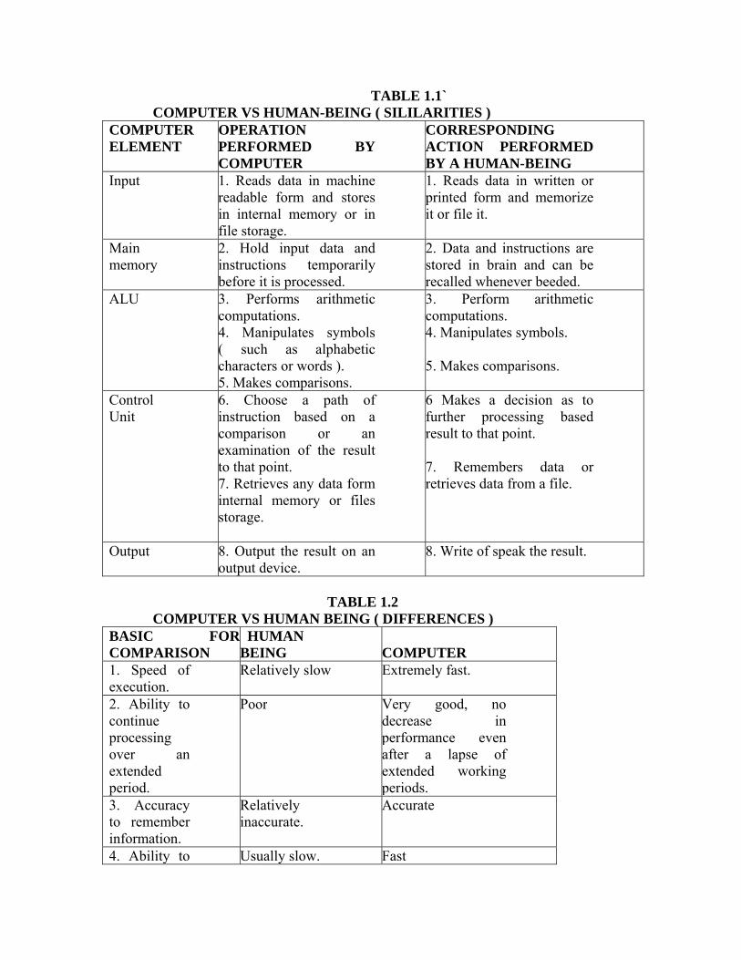
TABLE 1.1` COMPUTER VS HUMAN-BEING ( SILILARITIES )
COMPUTER ELEMENT
OPERATION PERFORMED BY COMPUTER
CORRESPONDING ACTION PERFORMED BY A HUMAN-BEING
Input 1. Reads data in machine readable form and stores in internal memory or in file storage.
1. Reads data in written or printed form and memorize it or file it.
Main memory
2. Hold input data and instructions temporarily before it is processed.
2. Data and instructions are stored in brain and can be recalled whenever beeded.
ALU 3. Performs arithmetic computations. 4. Manipulates symbols ( such as alphabetic characters or words ). 5. Makes comparisons.
3. Perform arithmetic computations. 4. Manipulates symbols.
5. Makes comparisons.
Control Unit
6. Choose a path of instruction based on a comparison or an examination of the result to that point. 7. Retrieves any data form internal memory or files storage.
6 Makes a decision as to further processing based result to that point.
7. Remembers data or retrieves data from a file.
Output 8. Output the result on an output device.
8. Write of speak the result.
TABLE 1.2 COMPUTER VS HUMAN BEING ( DIFFERENCES )
BASIC FORCOMPARISON
HUMAN BEING
COMPUTER
1. Speed of execution.
Relatively slow Extremely fast.
2. Ability to continue processing over an extended period.
Poor Very good, no decrease in performance even after a lapse of extended working periods.
3. Accuracy to remember information.
Relatively inaccurate.
Accurate
4. Ability to Usually slow. Fast
retrieve information. 5. Accuracy of work.
Makes error Makes virtually no errors.
6. Ability to consistently follow instructions.
Imperfect and may be malicious.
Perfect, if properly programmed.
7. Ability to innovate in new situation.
Fairly good. Totally absent.
8. Ability to learn by trial and error.
Fairly good. Totally absent.
1.5 Representation of Information inside a Computer Digital Computers use Binary number system to represent all types of information
inside the computers. Binary number system is suitable for this purpose due to
following reasons:
• Electronic components in digital computers operate in binary mode. A
switch is either on (1) or off (0); a transistor is either conducting (1) or
non-conducting(0).
• Computers have to handle only two digits (bits) rather than 10. So binary
system simplifies design, reduce the cost and improve the reliability of the
computer.
• Everything that can be done with decimal system can also be done using a
binary system.
Character Codes-Representation of alphanumeric characters in bits 0 and
1 is done by character codes. There are three widely used character codes:
• Binary Coded Decimal(BCD) • American standard Code for Information Interchange (ASCII) • Extended Binary Coded Decimal Interchange Code(EBCDIC)
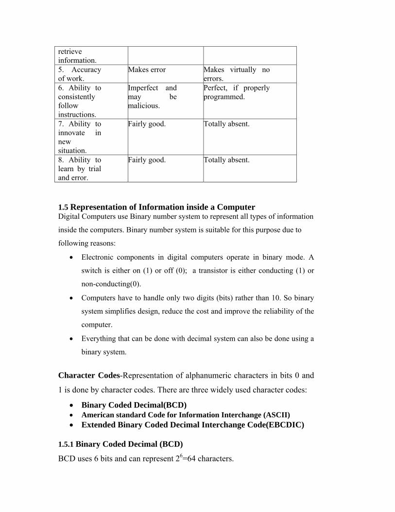
1.5.1 Binary Coded Decimal (BCD)
BCD uses 6 bits and can represent 26=64 characters.
The first three bits are used as zone bits and the last three bits indicate the
digit.
0 1 2 3 4 5
zone numeric
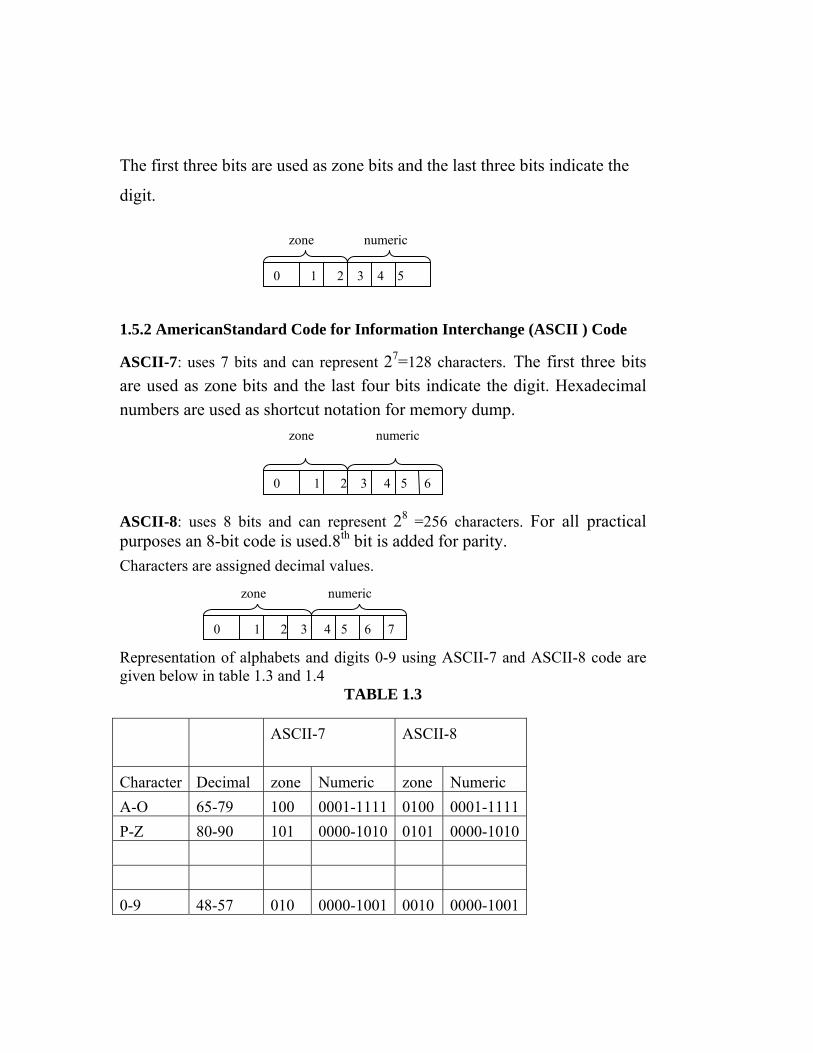
1.5.2 AmericanStandard Code for Information Interchange (ASCII ) Code
ASCII-7: uses 7 bits and can represent 27=128 characters. The first three bits are used as zone bits and the last four bits indicate the digit. Hexadecimal numbers are used as shortcut notation for memory dump. zone numeric
0 1 2 3 4 5 6 ASCII-8: uses 8 bits and can represent 28 =256 characters. For all practical purposes an 8-bit code is used.8th bit is added for parity. Characters are assigned decimal values.
0 1 2 3 4 5 6 7
numeric zone Representation of alphabets and digits 0-9 using ASCII-7 and ASCII-8 code are given below in table 1.3 and 1.4
TABLE 1.3
ASCII-7 ASCII-8
Character Decimal zone Numeric zone Numeric A-O 65-79 100 0001-1111 0100 0001-1111P-Z 80-90 101 0000-1010 0101 0000-1010 0-9 48-57 010 0000-1001 0010 0000-1001

TABLE 1.4 Character 6-bit BCD 7-bit
ASCII
8-bit ASCII
8-bit EBCDIC
0 ………….
011 0000 1111 0000
……….. …………
1111 1001 1100 0001
9 101 1001 A 100 0001 B 100 0010 1100 0010
…………. ……….. 1110 1001 Z 101 1010
1.5.3 Extended Binary Coded Decimal Interchange Code (EBCDIC)
It is an 8 bit code. It can represent 28 =256 characters. It is two groups of 4 digits.
Each group represents a hexadecimal number, used as shortcut notation for binary
numbers.
0 1 2 3 4 5 6 7
numeric zone
EBCDIC Character zone Numeric A-I 1100 0001-1001 J-R 1101 0001-1001 S-Z 1110 0010-1001 0-9 1111 0000-1001 RAJIV in ASCII-8 65 66 67 68 69 70 71 72 73 74 75 76 77 78 79 80 81 82 83 84 85 86 87 88 89 90 A B C D E F G H I J K L M N O P Q R S T U V W X Y Z R A J I V Decimal 82 65 74 73 86 ASCII-8 0101 0010 0100 0001 0100 1010 0100 1001 0101 0110
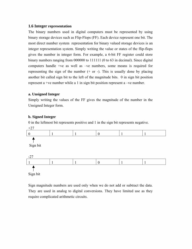
1.6 Integer representation The binary numbers used in digital computers must be represented by using binary storage devices such as Flip-Flops (FF). Each device represent one bit. The most direct number system representation for binary valued storage devices is an integer representation system. Simply writing the value or states of the flip-flops gives the number in integer form. For example, a 6-bit FF register could store binary numbers ranging from 000000 to 111111 (0 to 63 in decimal). Since digital computers handle +ve as well as –ve numbers, some means is required for representing the sign of the number (+ or -). This is usually done by placing another bit called sign bit to the left of the magnitude bits. 0 in sign bit position represent a +ve number while a 1 in sign bit position represent a –ve number. a. Unsigned Integer Simply writing the values of the FF gives the magnitude of the number in the Unsigned Integer form. b. Signed Integer 0 in the leftmost bit represents positive and 1 in the sign bit represents negative. +27 0 1 1 0 1 1 Sign bit -27 1 1 1 0 1 1 Sign bit Sign magnitude numbers are used only when we do not add or subtract the data. They are used in analog to digital conversions. They have limited use as they require complicated arithmetic circuits.
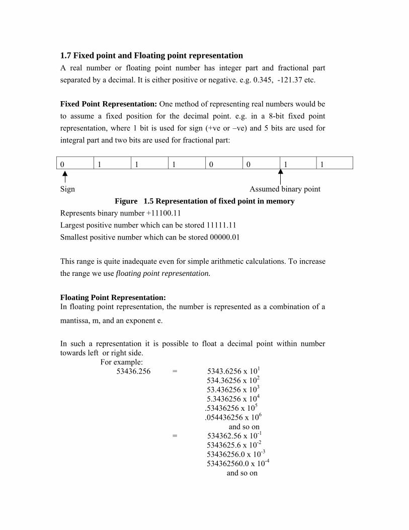
1.7 Fixed point and Floating point representation A real number or floating point number has integer part and fractional part separated by a decimal. It is either positive or negative. e.g. 0.345, -121.37 etc. Fixed Point Representation: One method of representing real numbers would be to assume a fixed position for the decimal point. e.g. in a 8-bit fixed point representation, where 1 bit is used for sign (+ve or –ve) and 5 bits are used for integral part and two bits are used for fractional part: 0 1 1 1 0 0 1 1 Sign Assumed binary point
Figure 1.5 Representation of fixed point in memory Represents binary number +11100.11 Largest positive number which can be stored 11111.11 Smallest positive number which can be stored 00000.01 This range is quite inadequate even for simple arithmetic calculations. To increase the range we use floating point representation. Floating Point Representation: In floating point representation, the number is represented as a combination of a
mantissa, m, and an exponent e.
In such a representation it is possible to float a decimal point within number towards left or right side.
For example: 53436.256 = 5343.6256 x 101
534.36256 x 10²
53.436256 x 10³
5.3436256 x 10⁴
.53436256 x 105
.054436256 x 106
and so on = 534362.56 x 10-1
5343625.6 x 10-2
53436256.0 x 10-3
534362560.0 x 10-4
and so on

Floating Point Number
Mantissa Exponent
5343.6256 x 101 5343.6256 1 534.36256 x 10² 534.36256 2 53.436256 x 10³ 53.436256 3 5.3436256 x 10⁴ 5.3436256 4 .53436256 x 105 .53436256 5 0.053436256 x 10⁶ 0.053436256 6 ……………. ………… …………
In general floating representation of a number of any base may be written as:
N = ±Mantissa x (Base) ±exponent
Representation of floating point number in computer memory (with four digit mantissa) Let us assume we have hypothetical 8 digit computer out of which four digits are used for mantissa and two digits are used for exponent with a provision of sign of mantissa and sign of exponent. Implied decimal point
± ±
Figure 1.5 Floating point representation in memory(4 digit mantissa) Normalized Floating Representation It has been noted that a number may have more than one floating point
representations. In order to have unique representation of non-zero numbers a
normalized floating point representation is used.
A floating point representation in decimal number system is normalized floating
point iff mantissa is less than 1 and greater than equal to .1 or 1/10(base of
decimal number system).
534362.56 x 10-1 534362.56 -1
Normalized Floating Point Number
5343625.6 x 10-2 5343625.6 -2 53436256.0 x 10-3 53436256.0 -3 534362560.0 x 10-4 534362560.0 -4 …………. ………… ……
Mantissa Exponent Sign of exponent
Sign of Mantissa
i.e.
.1≤ |mantissa| <1
A floating point representation in binary number system is normalized floating
point iff mantissa is less than 1 and greater than equal to .5 or 1/2(base of binary
number system).
i.e.
.5≤ |mantissa| <1 In general, a floating point representation is called normalized floating point representation iff mantissa lies in the range:
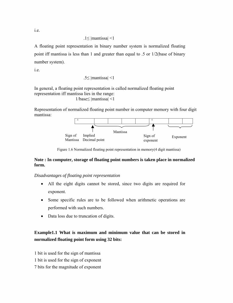
1/base≤ |mantissa| <1 Representation of normalized floating point number in computer memory with four digit mantissa: ± ±
Sign of Implied Mantissa Decimal point Figure 1.6 Normalized floating point representation in memory(4 digit mantissa)
Sign of exponent
Exponent
Mantissa
Note : In computer, storage of floating point numbers is taken place in normalized form. Disadvantages of floating point representation
• All the eight digits cannot be stored, since two digits are required for
exponent.
• Some specific rules are to be followed when arithmetic operations are
performed with such numbers.
• Data loss due to truncation of digits.
Example1.1 What is maximum and minimum value that can be stored in normalized floating point form using 32 bits: 1 bit is used for the sign of mantissa 1 bit is used for the sign of exponent 7 bits for the magnitude of exponent
23 bits for the magnitude of mantissa Maximum magnitude of e=11111112=12710
Magnitude of m varies from 0.12 to 0.111111111….2.
0.5 10 to (1-2 23)10
(1-2 23)10 is roughly 1 Hence max value= 1x2127=1.7x10 38
Min. value=.5x2 -127=.3x10 -38
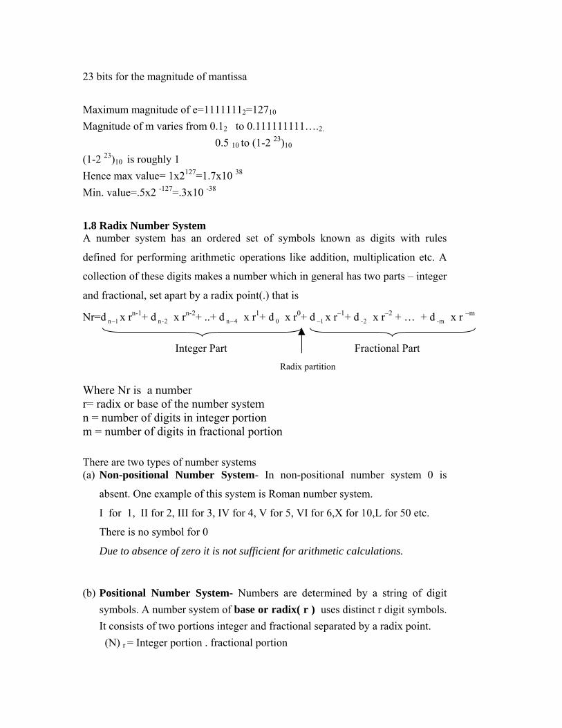
1.8 Radix Number System A number system has an ordered set of symbols known as digits with rules
defined for performing arithmetic operations like addition, multiplication etc. A
collection of these digits makes a number which in general has two parts – integer
and fractional, set apart by a radix point(.) that is
Nr=d x r1n−n-1+ d x r2-n
n-2+ ..+ d x r4n−1+ d 0 x r0+ d x r1−
–1+ d x r2-–2 + … + d x r m-
–m
Where Nr is a number
Radix partition
Fractional Part Integer Part
r= radix or base of the number system n = number of digits in integer portion m = number of digits in fractional portion There are two types of number systems (a) Non-positional Number System- In non-positional number system 0 is
absent. One example of this system is Roman number system.
I for 1, II for 2, III for 3, IV for 4, V for 5, VI for 6,X for 10,L for 50 etc.
There is no symbol for 0
Due to absence of zero it is not sufficient for arithmetic calculations.
(b) Positional Number System- Numbers are determined by a string of digit symbols. A number system of base or radix( r ) uses distinct r digit symbols. It consists of two portions integer and fractional separated by a radix point.
(N) r = Integer portion . fractional portion
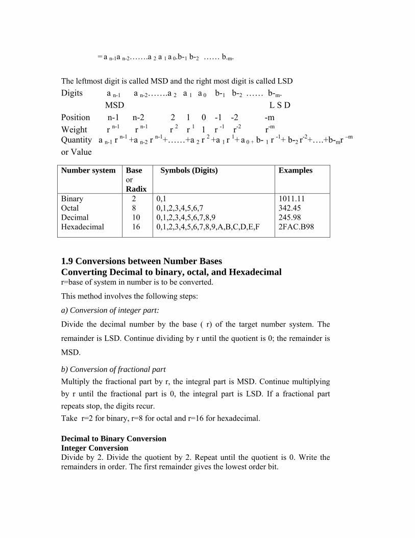
= a n-1a n-2…….a 2 a 1 a 0.b-1 b-2 …… b-m. The leftmost digit is called MSD and the right most digit is called LSD
Digits a n-1 a n-2…….a 2 a 1 a 0 b-1 b-2 …… b-m. MSD L S D Position n-1 n-2 2 1 0 -1 -2 -m Weight r n-1 r n-1 r 2 r 1 1 r -1 r-2 r-m Quantity a n-1 r n-1 +a n-2 r n-1+……+a 2 r 2 +a 1 r 1+ a 0 + b- 1 r -1+ b-2 r-2+….+b-mr –m or Value
Number system Base
or Radix
Symbols (Digits) Examples Binary 2 0,1 1011.11 Octal 8 0,1,2,3,4,5,6,7 342.45 Decimal 10 0,1,2,3,4,5,6,7,8,9 245.98
Hexadecimal 16 0,1,2,3,4,5,6,7,8,9,A,B,C,D,E,F 2FAC.B98
1.9 Conversions between Number Bases Converting Decimal to binary, octal, and Hexadecimal r=base of system in number is to be converted.
This method involves the following steps:
a) Conversion of integer part:
Divide the decimal number by the base ( r) of the target number system. The
remainder is LSD. Continue dividing by r until the quotient is 0; the remainder is
MSD.
b) Conversion of fractional part Multiply the fractional part by r, the integral part is MSD. Continue multiplying by r until the fractional part is 0, the integral part is LSD. If a fractional part repeats stop, the digits recur. Take r=2 for binary, r=8 for octal and r=16 for hexadecimal. Decimal to Binary Conversion Integer Conversion Divide by 2. Divide the quotient by 2. Repeat until the quotient is 0. Write the remainders in order. The first remainder gives the lowest order bit.
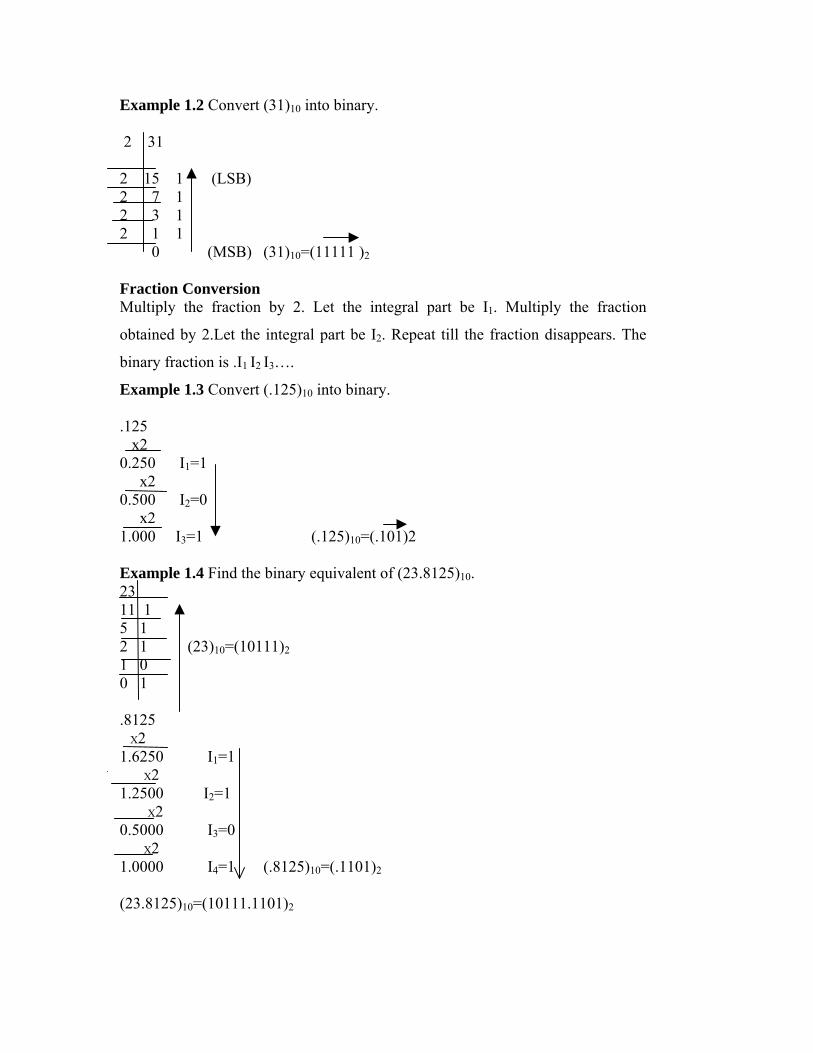
Example 1.2 Convert (31)10 into binary. 2 31
2 15 1 (LSB)
2 7 1 2 3 1 2 1 1 0 (MSB) (31)10=(11111 )2 Fraction Conversion Multiply the fraction by 2. Let the integral part be I1. Multiply the fraction
obtained by 2.Let the integral part be I2. Repeat till the fraction disappears. The
binary fraction is .I1 I2 I3….
Example 1.3 Convert (.125)10 into binary. .125 x2 0.250 I1=1 x2 0.500 I2=0 x2 1.000 I3=1 (.125)10=(.101)2 Example 1.4 Find the binary equivalent of (23.8125)10. 23 11 1 5 1 2 1 (23)10=(10111)2 1 0 0 1 .8125 X2 1.6250 I1=1 X2 1.2500 I2=1 X2 0.5000 I3=0 X2 1.0000 I4=1 (.8125)10=(.1101)2
(23.8125)10=(10111.1101)2

Decimal to Hexadecimal Conversion Conversion of a decimal into a hexadecimal is similar to that of converting a
decimal into its binary equivalent. The decimal part is divided by 16 until it
becomes 0 for integer part conversion. The remainders are than arranged in
reverse order. Similarly the fraction part is converted by multiplying by 16 until
the fraction part reduces to 0. Then the integer part in these multiples is collected
in the order of appearance.
Example1.5 : Convert decimal number 755.9375 to its hexadecimal equivalent. 755 divide by 16 remainder 3 (Quotient 47) 47 divide by 16 remainder 15 (i.e.F) (Quotient 2) 2 divide by 16 remainder 2 (Quotient 0) hence (755)10 = (2F3)16Now we convert the fraction part .9375
Fraction Integer part=15 i.e. F 0000.1516
9375.0×
Fraction 0.0000 Hence (0.9375)10 = (F)16Therefore (755.9375)10 = (2F3.F)16 Converting Binary, Octal, and Hexadecimal to Decimal Conversion of a binary, octal, and hexadecimal number to decimal number
involves each digit of the binary, octal, or hexadecimal number to be multiplied
by its weighted position, and then each of the weighted values is added together to
get the decimal number.
an an-1an-2….a0. a-1 a-2…..a-mn n-1 n-2 0 9 -1 -2 -m
can be obtained as 2n × an+2n-1 × an-1+……+20 × a0 +2-1 × a-1+……2-m× a-m Example 1.6 Convert the binary number (0110.001)2 into decimal. Sol. The decimal equivalent is 23 × 0+22 × 1+21 × 1+20 × 0+2-1 × 0+2-2 × 0 +2-3 × 1=6.125 Thus the decimal equivalent of (0110.001) is 6.125 Example 1.7 Determine decimal equivalent of (456)8
Sol. 82 × 4+81 × 5+80 × 6= 256+40+6

= 302 Thus the decimal equivalent of (456)8 is (302)10 Example1.8 Determine decimal equivalent of (B14)16
Sol. 162 × B+161 × 1+160 × 4 = 162 × 11+161 × 1+160 × 4 = 2816+16+4=2836 Thus the decimal equivalent of (B14)16 is (2836)10
Converting among Binary, Octal, and Hexadecimal Converting among binary, octal, and hexadecimal can accomplished easily without converting to decimal, since base numbers(2, 8, and 16) of all three number systems are powers of 2. Any octal digit can be written as group of three binary digits while a hexadecimal digit corresponds to four binary digits. So the conversion is accomplished by partitioning the binary number into group of three or four digits. Example 1.9 Determine octal equivalent of (010111)2
Sol 010 111
2 7 Thus the octal equivalent of (010111)2 is (27)8
Example 1.10 Determine binary equivalent of (231)8
Sol 2 3 1 010 011 001 Thus the binary equivalent of (231)8 is 010011001 Example 1.11 Convert (11011101.11010101)2 into its hexadecimal equivalent
5
01011313
1101.110113
1101 hence (11011101.11010101)2= (DD.D5)16
Thus the hexadecimal equivalent of 1101 1101 . 1101 0101 is DD.D5 Hexadecimal to Binary conversion Replace each digit by a set of four binary digits and group these together. Example1.12 Convert (765.3)16 into binary
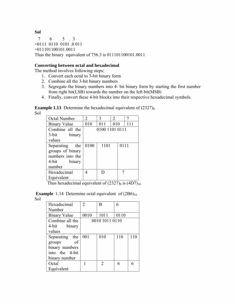
Sol 7 6 5 . 3 =0111 0110 0101 .0 011 =011101100101.0011 Thus the binary equivalent of 756.3 is 011101100101.0011 Converting between octal and hexadecimal The method involves following steps:
1. Convert each octal to 3-bit binary form 2. Combine all the 3-bit binary numbers 3. Segregate the binary numbers into 4- bit binary form by starting the first number
from right bit(LSB) towards the number on the left bit(MSB) 4. Finally, convert these 4-bit blocks into their respective hexadecimal symbols.
Example 1.13 Determine the hexadecimal equivalent of (2327)8Sol
Octal Number 2 3 2 7 Binary Value 010 011 010 111 Combine all the 3-bit binary values
0100 1101 0111
Separating the groups of binary numbers into the 4-bit binary number
0100 1101 0111
Hexadecimal Equivalent
4 D 7
Thus hexadecimal equivalent of (2327)8 is (4D7)16 Example 1.14 Determine octal equivalent of (2B6)16Sol
Hexadecimal Number
2 B 6
Binary Value 0010 1011 0110 Combine all the 4-bit binary values
0010 1011 0110
Separating the groups of binary numbers into the 4-bit binary number
001 010 110 110
Octal Equivalent
1 2 6 6
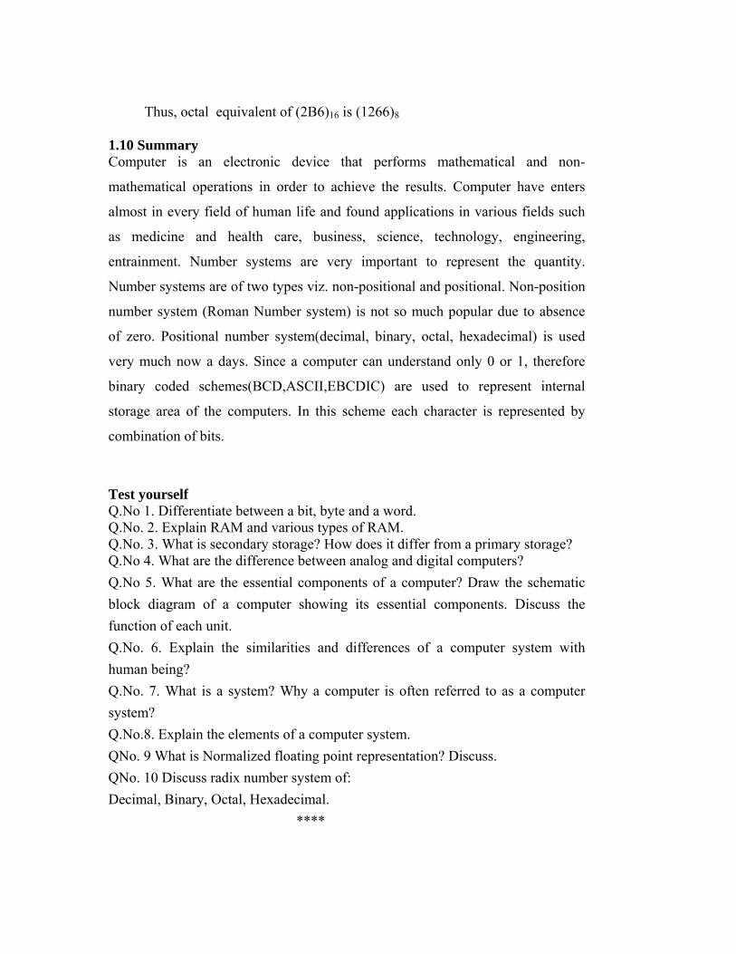
Thus, octal equivalent of (2B6)16 is (1266)8 1.10 Summary Computer is an electronic device that performs mathematical and non-
mathematical operations in order to achieve the results. Computer have enters
almost in every field of human life and found applications in various fields such
as medicine and health care, business, science, technology, engineering,
entrainment. Number systems are very important to represent the quantity.
Number systems are of two types viz. non-positional and positional. Non-position
number system (Roman Number system) is not so much popular due to absence
of zero. Positional number system(decimal, binary, octal, hexadecimal) is used
very much now a days. Since a computer can understand only 0 or 1, therefore
binary coded schemes(BCD,ASCII,EBCDIC) are used to represent internal
storage area of the computers. In this scheme each character is represented by
combination of bits.
Test yourself Q.No 1. Differentiate between a bit, byte and a word. Q.No. 2. Explain RAM and various types of RAM. Q.No. 3. What is secondary storage? How does it differ from a primary storage? Q.No 4. What are the difference between analog and digital computers? Q.No 5. What are the essential components of a computer? Draw the schematic block diagram of a computer showing its essential components. Discuss the function of each unit. Q.No. 6. Explain the similarities and differences of a computer system with human being? Q.No. 7. What is a system? Why a computer is often referred to as a computer system? Q.No.8. Explain the elements of a computer system. QNo. 9 What is Normalized floating point representation? Discuss. QNo. 10 Discuss radix number system of: Decimal, Binary, Octal, Hexadecimal. ****

Subject: Computer Fundamentals Author: Dr. Pradeep Bhatia Paper Code: MCA 101 Vetter: Sh. Dinesh Chutani Lesson: Input Devices Lesson No. : 02 Structure 2.0 Objective 2.1 Introduction 2.2. Input Devices 2.2.1 Keyboard 2.2.2 Pointing Devices 2.2.2.1 Mouse 2.2.2.2 Trackball 2.2.2.3 Joystick 2.2.2.4 Light Pen 2.2.2.5 Scanners 2.2.2.6 Optical Scanners 2.3 Summary 2.4 Self assessment questions 2.3 Output Devices 2.3.1 Hardcopy Devices 2.3.1.1 Impact Printers 2.3.1.2 Non-Impact Printers 2.3.1.3 Plotters 2.3.2. Softcopy Devices 2.3.2.1 Monitors 2.3.2.2 Projectors 2.3.2.3 Audio Output 2.4 Terminal 2.5 Summary 2.6 Self Assessment Questions

2.0 Objective A computer accepts (input) information and manipulates (processes) it to
get desired result (output) on a sequence of instructions. In the previous
lesson, we discussed that a computer system essentially consists of three
components: input devices, central processing unit, and output devices.
Input devices are used to provide data to the central processing unit for
processing. The aim of this lesson is to familiarise you with the various
types of input devices along with their advantages, disadvantages, and
applications.
2.1 Introduction
Input devices are used to provide data to the central processing unit for
processing. After processing, the input data is converted into meaningful
information and this output is presented to the user with the help of output
devices. In computer terminology devices can be refereed as a unit of
hardware, which is capable of providing input to the computer or receiving
output or both. An input device captures information and translates into
form understandable by computer and output devices(will be discus in
lesson number 3) translate information into form understandable by
human-being as shown in fig 2.1. Input devices let the user talk to the
computer. Output devices let the computer communicate to the user.
The common input devices are keyboards and mouse. The output devices
are monitors and printers.
Input Device
Data coded in computer Understandable form
Data coded in human Understandable form
Output Device
CPU
Figure 2.1 Interrelationship between Input device, CPU and Output
Device

2.2 Input Devices
Input devices can be broadly classified into the following categories:
2.2.1. Keyboard
2.2.2 Pointing Devices
2.2.3. Speech Recognition
2.2.4. Digital Camera
2.2.5 Scanners
2.2.6. Optical Scanners
2.2.1 Keyboard
Keyboard is designed to resemble a regular typewriter with a few
additional keys. A keyboard is the most common data entry device. Using
a keyboard, the user can type text and execute commands. Data is entered
into computer by simply pressing various keys. The layout of a keyboard
come in various styles such as QWERTY, DVORAK, AZERTY but the
most common layout is the QWERTY. It is named so because the first six
keys on the top row of letters are Q,W E, R, T, and Y. The number of keys
on a typical keyboard varies from 82 keys to 108 keys. Portable computers
such as laptops quite often have custom keyboards that have slightly
different key arrangements than a standard keyboard. In addition, many
system manufacturers add special buttons to the standard layout.
Keyboard is the easiest input device, as it does not require any special
skill, it is supplied with a computer so no additional cost is incurred. The
maintenance and operation cost of keyboard is also less. However, using a
keyboard for data entry may be a slow process.
Fig 2.2

Layout of the Keyboard
The layout of the keyboard can be divided into the following five sections:
Typing Keys: These keys include the letter keys (1, 2, A, B, etc.), which
are generally laid out in the same style that was common for typewriters.
Numeric Keypad: Numeric keys are located on the right hand side of the
keyboard. Generally, it consists of a set of 17 keys that are laid out in the
same configuration used by most adding machines and calculators.
Function Keys: The functions keys (FI, F2, F3, etc.) are arranged in a row
along the top of the keyboard and could be assigned specific commands by
the current application or the operating system.
Control Keys: These keys provide cursor and screen control. It includes
four directional arrows(← ↑ → ↓ ). These keys allow the user to move the
cursor on the display area one space at a time in either an up, down, left or
right direction. Control keys also include Home, End, Insert, Delete, Page
Up, Page Down, Control (Ctrl), Alternate (A It), and Escape (Esc).
Special Purpose Keys: Apart from the above-mentioned keys, a keyboard
contains some special purpose keys such as Enter, Shift, Caps Lock, Num
Lock, Spacebar, Tab, and Print Screen.
Working of a Keyboard
A keyboard is series of switches connected to a small keyboard
microprocessor. When the user presses a key, it causes a change in the
amount of current flowing through the circuit associated specifically with
that key. The keyboard microprocessor detects this change in current flow.
By doing this, the processor can tell when a key has been pressed and
when it is being released. The processor generates the associative code,
known as scan code, of the key and sends it to the operating system. A
copy of this code is also stored in the keyboard's memory.

2.2.2 Pointing Devices
In some applications, keyboard is not convenient. For example, if the user
wants to select an item from a list, the user can identify that items position
by selecting it through the keyboard. However, this action could be
performed quickly by pointing at correct position. A pointing device is
used to communicate with the computer by pointing to location on the
screen. Some of the commonly used pointing devices are mouse,
trackball, joystick, light pen, and touch panel.
2.2.2.1 Mouse
Mouse is a small hand-held pointing device, which is rectangular-shaped
with a rubber ball embedded at its lower side and buttons on the top.
Usually a mouse contains two or three buttons, which can be used to input
commands or information. Figure 3.3 shows a mouse with three buttons.
Figure 2.3 Mouse
The mouse may be classified as a mechanical mouse or an optical mouse,
based on technology it uses.
A mechanical mouse uses a rubber ball at the bottom surface, which
rotates as the mouse is moved along a flat surface, to move the cursor.
Mechanical mouse is the most common and least expensive pointing
device. Microsoft, IBM, and Logitech are some well-known makers of the
mechanical mouse.
An optical mouse uses a light beam instead of a rotating ball to detect
movement across a specially patterned mouse pad. As the user rolls the

mouse on a flat surface, the cursor on the screen also moves in the
direction of the mouse's movement.
An optical mouse has the following benefits over the mechanical mouse:
• No moving part means less wear and a lower chance of failure.
• Dirt cannot get inside the mouse and hence no interference with the
tracking sensors.
• They do not require a special surface such as a mouse pad.
The cursor of the mouse can be text cursor or graphic cursor. The text
cursor(I) is used for text while the graphic cursor( )is used for pointing
and drawing.
A mouse allows us to create graphic elements on the screen, such as lines,
curves, and freehand shapes. Since it is an intuitive device, it is much
easier and convenient to work as compared to the keyboard. Like keyboard,
usually it is also supplied with a computer; therefore, no additional cost is
incurred. The mouse cannot easily be used with laptop, notebook or
palmtop computers. These need a track ball or a touch sensitive pad called
a touch pad.
Working of a mouse
A mechanical mouse has a rubber ball in the bottom. When the user
moves the mouse, the ball rolls along the surface of the mouse pad, and
the mouse keeps track of how far the ball rolls. This allows it to tell how
far it has moved. Inside the bottom of the mouse are three rollers. These
rollers are mounted at a 90° angle to the one other, one roller measures
how fast the ball is turning horizontally, and the other measures how fast
it is turning vertically. When the ball rolls, it turns these two rollers. The
rollers are connected to axles, and the axles are connected to a small
sensor that measures how fast the axle is turning. Both sets of information
are passed to the electronics inside the mouse. This little processor,
usually consisting of little more than a single chip, uses the information to
determine how fast the mouse itself is Processor Chip moving, and in

what direction. This information is passed to the computer via mouse cord,
where the operating system then moves the pointer accordingly.
The optical mouse uses an infrared light and special mouse pads with fine
grid lines to measure the rotation of the axle. The axle in optical mouse is
connected to a little photo-interrupter wheel with a number of tiny holes in
it. In front of this wheel is a light and on the other side of the wheel is a
light meter. As the wheel turns, the light flashes through the holes in the
wheel. By measuring how often these flashes occur, the light sensor can
measure how fast the wheel is turning and sends the corresponding
coordinates to the computer. The computer moves the cursor on the screen
based on the coordinates received from the mouse. This happens hundreds
of times each second, making the cursor appear to move very smoothly.
2.2.2.2 Trackball
Trackball is another pointing device that resembles a ball nestled in a
square cradle and serves as an alternative to a mouse. In general, a
trackball is as if a mouse is turned upside down. It has a ball, which can be
rotated by fingers in any direction, the cursor moves accordingly. The size
of the ball of the trackball varies from as large as a cue ball, to as small as
a marble. Since, it is a static device so rather than rolling the mouse on the
top of the table, the ball on the top is moved by using fingers, thumbs, and
palms.
This pointing device comes in various shapes and forms but with the same
functionality. The three shapes, which are commonly used, are a ball, a
button, and a square.

Figure 2.4 Trackball
2.2.2.3 Joystick
Joystick is a device that moves in all directions and controls the movement
of the cursor. The joystick offers three types of control: digital, glide, and
direct.
Digital control allows movement in a limited number of directions such as
up, down, left, and right.
Glide and direct control allow movements in all directions (360 degrees).
Direct control joysticks have the added ability to respond to the distance
and speed which user moves the stick.
A joystick is generally used to control the velocity of the screen cursor
movement rather than its absolute position. Joysticks are mainly used for
computer games, for other applications, which includes flight simulators,
training simulators, CAD/CAM systems, and for controlling industrial
robots.
Figure 2.5 Joystick
2.2.2.4 Light Pen
It is the pen like device, which is connected to the machine by a cable. A
light pen (sometimes called a mouse pen) is a hand-held electro-optical
pointing device which when touched to or aimed closely at a connected
computer monitor, will allow the computer to determine where on that
screen the pen is aimed. It actually does not emit light; its light sensitive-
diode would sense the light coming from the screen. The light coming

from the screen causes the photocell to respond by generating a pulse. This
electric response is transmitted to the processor that identifies the position
to which the light pen is pointing. With the movement of light pen over the
screen, the lines or images are drawn.
Figure 2.6 Light Pen
It facilitates drawing images and selects objects on the display screen by
directly pointing the objects with the pen.
2.2.2.5 Digital Camera
Digital camera stores images digitally rather than recording them on a
film. Once a picture has been taken, it can be downloaded to a
computer system and then manipulated with an image editing software
and printed. The big advantage of digital cameras is that making photos
is both inexpensive and fast because there is no film processing.

Figure 2.7 Digital Camera
All digital cameras record images in an electronic form, that is, the image
is represented in computer's language, the language of bits and bytes.
Essentially, a digital image is just a long string of 1's and 0's that represent
all the tiny colored dots or pixels that collectively make up the image. Just
like a conventional camera, it has a series of lenses that focus light to
create an image of a scene.
Basic difference between digital camera and film-based cameras is that the
digital camera does not have a film; it has a sensor that converts light into
electrical charges.
2.2.2.6 Scanners
There are a number of situations when some information (picture or text)
is available on paper and is needed on the computer disk for further
manipulation. The simplest way would be to take a photograph of the
image directly from the source and convert it into a form that can be saved
on the disk. A scanner scans an image and transforms the image to ASCII
codes (the code used by a computer to represent the characters you find on
your keyboard - letters of the alphabet, numbers, punctuation marks, etc.)
and graphics. These can be edited, manipulated, combined, and then
printed.
Scanners use a light beam to scan the input data. If the data to be scanned
is an image, it can be changed by using the special image editing software.
If the image is a page of text, then the special optical character recognition
software must be used to covert the images of letters in text and this can
be edited by using a word processor.
The two most common types of scanners are hand-held scanner and flat-
bed scanner.
Hand-Held Scanner
A hand-held scanner consists of light emitting diodes, which are placed
over the material to be scanned. This scanner performs the scanning of the

document very slowly from the top to the bottom, with its light on. In this
process, all the documents are converted and then stored as an image.
While working, the scanner is dragged very steadily and carefully over the
document and it should move at a constant speed without stopping, or
jerking in order to obtain best results. Due to this reason, hand-held
scanners are widely used where high accuracy is not of much importance.
The size of the hand-held scanners is
(a) Hand-held scanner (b) Flat-Bed scanner
Figure 2.8
small shown in fig 2.10(a). They come in various resolutions, up to about
800 dpi (dots per inch) and are available in either grey scale or colour.
Flat-Bed Scanner
Flat-bed scanners look similar to a photocopier machine. It consists of a
box containing a glass plate on its top and a lid that covers the glass plate.
This glass plate is primarily used for placing the document to be scanned.
The light beam is placed below the glass plate and when it is activated, it
moves from left to right horizontally. After scanning one line, the beam of
light moves in order to scan the next line and thus, the procedure is
repeated until all the lines are scanned. For scanning, an A4 size document
takes about 20 seconds. These scanners are capable of scanning black and
white as well as colour images. The flat-bed scanners are larger in size
and more expensive than the hand-held scanners shown in fig. 2.10(b).

However, they usually produce better quality images because they employ
better scanning technology.
2.2.2.7 Optical Scanners
There are four types of optical recognition: optical character
recognition (OCR), optical mark recognition (OMR), magnetic ink
character recognition (MICR), and bar code reader.
Optical Character Recognition (OCR)
Optical Character Recognition (OCR) is a process of scanning printed
pages as images on a flatbed scanner and then using OCR software to
recognise the letters as ASCII text. The OCR software has tools for
both acquiring the image from a scanner and recognising the text. In the
OCR system, a book or a magazine article is fed directly into an
electronic computer file, and then this file is edited by using a word
processor. Advanced OCR systems can read text in a large variety of
fonts, but they still have difficulty with handwritten text. OCR works
best with originals or very clear copies and mono-spaced fonts like
Courier.
Figure 2.9 OCR System

Optical Mark Recognition
(OMR)
Optical Mark Recognition (OMR) is the process of detecting the presence
of intended marked responses. A mark registers significantly less light
than the surrounding paper. Optical mark reading is done by a special
device known as optical mark reader. The OMR technology enables a
high speed reading of large quantities of data and transferring this data to
computer without using a keyboard. The OMR reader scans the form,
detects the presence of marks, and passes this information to the computer
for processing by application software. Generally, this technology is used
to read answer sheets (objective type tests). In this method, special printed
forms/documents are printed with boxes, which can be marked with dark
pencil or ink. These forms are then passed under a light source and the
presence of dark ink is transformed into electric pulses, which are
transmitted to the computer.
Figure 2.10 Optical Mark Recognition
Optical mark recognition is also used for standardised testing as well as
course enrolment and attendance in education.
OMR has a better recognition rate than OCR because fewer mistakes are
made by machines to read marks than in reading handwritten characters.
Large volumes of data can be collected quickly and easily without the need
for specially trained staff. Usually, an OMR reader can maintain a

throughput of 1500 to 10000 forms per hour. It requires accurate alignment
of printing on forms and need a paper of good quality.
Optical mark recognition is traditionally performed using reflective light
method where a beam of light is reflected on a sheet with marks, to capture
the reflection (presence of mark) or absence of reflection (absence of
mark).
Magnetic-Ink Character Recognition (MICR)
Specifically, it refers to the special magnetic encoding, printed on the
bottom of a negotiable check. This information is machine readable via
bank reader/sorters, which read the visual patterns and magnetic
waveforms of the MICR encoding.
The characters are printed using special ink, which contains iron particles
that can be magnetised. Magnetic ink character readers are used generally
in banks to process the cheques. In case of bank cheques, the numbers
written at the bottom are recorded in MICR (using special magnetic ink),
representing unique cheque numbers, bank, and branch code, etc. A MICR
reads these characters by examining their shapes in a matrix form and the
information is then passed on to the computer.
Figure 2.11 Magnetic-Ink Character Recognition
The banking industry prefers MICR because as compared to the OCR, it
gives extra security against forgeries such as colour copies of payroll
cheques or hand-altered characters on a cheque. The reading speed of the
MICR is also higher. This method is very efficient and time saving for data
processing.

Bar Code Reader
Bar code is a machine-readable code in the form of a pattern of parallel
vertical lines of varying widths. They are commonly used for labelling
goods that are available in super markets, numbering books in libraries,
etc. These codes/stripes are sensed and read by a photoelectric device (bar
code reader) that reads the code by means of reflective light. The
information recorded in bar code reader is then fed into the computer,
which recognises the information from the thickness and spacing of bars.
Bar code readers are either hand-held or fixed-mount. Hand-held scanners
are used to read bar codes on stationary items. With fixed-mount scanners,
items having a bar code are passed by the scanner - by hand as in retail
scanning applications or by conveyor belt in many industrial applications.
A bar code scanner can record data five to seven times faster than a
skilled typist can record. A bar code data entry has an error rate of about I
in 3 million. Bar coding also reduces cost in terms of labour and reduced
revenue losses resulting from data collection errors.
Figure 2.12 Hand-held bar code reader
2.4 Summary
An input device is an electromechanical device which accepts converts the
data or information from user and translates the information into form
understandable by machine. Keyboards are the most commonly used data

entry input devices. Pointing devices (Mouse, Light pen, Touch panel) are
very much popular in GUI software.
2.5 Self assessment questions 1. What are the pointing devices? Explain in detail some of the commonly used pointing devices. 2. Differentiate between: a) Touch panel and Light pen b) Hand-held and flatbed scanner. 3. List out the various optical scanning devices. Explain in detail. 4 Write the full form of following abbreviations: a) OMR b) MICR d)OCR
****

Subject: Computer Fundamentals Author: Dr. Pradeep Bhatia Paper Code: MCA 101 Vetter: Lesson: Output Devices Lesson No. : 03 3.0 Objective 3.1 Introduction 3.2 Classification of Output Devices 3.2.1 Hardcopy Devices 3.2.1.1 Impact Printers 3.2.1.2 Non-Impact Printers 3.2.1.3 Plotters 3.2.2. Softcopy Devices 3.2.2.1 Monitors 3.2.2.2 Projectors 3.2.2.3 Audio Output 3.3 Terminal 3.4 Summary 3.5 Self Assessment Questions

3.0 Objective
A computer accepts (input) information and manipulates (processes) it to
get desired result (output) on a sequence of instructions. In the previous
lesson, we have discussed various types of input devices used to provide
data to the central processing unit for processing. The aim of this lesson is
to familiarise you with the various types of output devices to get desired
result that may be in various form viz text, graphics, audio, and video;
along with their advantages, disadvantages, and applications.
3.1 Introduction
Output devices convert machine-readable information into human-
readable form. The basic functioning of output devices is just the opposite
of the input devices, that is, the data is 'fed into' the computer system
through the input devices while the output is 'taken out' from the computer
through the output devices. However, the output, which comes out from
CPU, is in the form of digital signals. The output devices display the
processed information by converting them into human-readable form in
graphical, alphanumeric or audio-visual forms.
3.2 Classification of Output Devices
Output is data that has been processed into a useful form called
information. It can be displayed or viewed on a monitor, printed on a
printer, or listened through speakers or a headset.

Text Audio Video Graphics
Output
Figure 3.1 Types of Output
There are four basic areas of the output devices:
Text: Textual form of output consists of characters (letters, numbers,
punctuation marks, or any other symbol requiring one byte of computer
storage space) that are used to create words, sentences, and paragraphs.
Graphics: Graphics are digital representations of non-text information
such as drawings, charts, photographs, and animation (a series of still
images in sequence that gives the illusion of motion).
Audio: Audio includes music, speech or any sound. A computer converts
the sound from a continuous analog signal into a digital format. Most
output devices require the computer to convert digital format back into
analog signals.
Video: Video consists of images that are played back at speed that provide
the illusion of full motion. The images are often captured with a video
input device like a video camera. A video capture card is required to
convert an analog video signal into a digital signal that the computer can
understand. Some output devices accept the digital signal, while others
convert the digital signals into analog signals.
The outputs, which can be easily understood and used by human beings,
are of following two forms:

1. Hard Copy: The physical form of output is known as hard copy. In
general, it refers to the recorded information copied from a computer onto
paper or some other durable surface, such as microfilm. Hard copy output
is permanent and relatively stable form of output. This type of output is
also highly portable. Paper is one of the most widely used hard copy
output media. The principal examples are printouts, whether text or
graphics, from printers. Film, including microfilm and microfiche, is also
considered as a hard copy output.
2 Soft Copy: The electronic version of an output, which usually resides in
computer memory and or on disk, is known as soft copy. Unlike hard copy,
soft copy is not a permanent form of output. It is transient and is usually
displayed on the screen. This kind of output is not tangible, that is, it
cannot be touched. Soft copy output includes audio and visual form of
output, which is generated using a computer. In addition, textual or
graphical information displayed on a computer monitor is also a soft copy
form of output.
Hard copy devices are very slow in operation as compared to the soft copy
devices.
Figure 3.2 Two types of outputs
Based on the hard copy and soft copy outputs, the output devices are
classified into two types: hard copy output devices and soft copy output
devices.

3.2.1 Hard Copy Output devices
Among the wide variety of the hard copy output devices, printers, and
plotters are the most commonly used. A printer is used to produce
printouts of the documents stored on a computer's disk drive. A plotter is a
pen-based output device, which is used for producing high quality output
by moving ink pens across the paper.
3.21.2 Impact Printers
As their names specify, impact printers work by physically striking a head
or needle against an ink ribbon to make a mark on the paper. Impact
printers are the oldest printing technology and are still in use. An impact
printers can print only one character at a time while some impact printers
can print an entire line. The three most commonly used impact printers are
dot matrix printers, daisy wheel printers, and drum printers.
Characteristics of impact printers
• In impact printers, there is physical contact with the paper to produce an
image.
• They have relatively low consumable costs. The primary recurring costs
for these printers are the ink ribbons and paper.
• Due to being robust and low cost, they are useful for bulk printing.
• They can withstand dusty environment, vibrations, and extreme
temperature.
• Impact printers are ideal for printing multiple copies (that is, carbon
copies) because they can easily print through many layers of paper.
• Due to its striking activity, impact printers are very noisy.
• Since they are mechanical in nature, they tend to be slow.
• Impact printers do not support transparencies.
Dot matrix printers
Dot matrix printer (also known as the wire matrix printer) is the oldest
printing technology and it prints one character at a time. Usually, dot
matrix printers can print any shape of character, which a user can specify.
This allows the printer to print many special characters, different sizes of

print, and enables it to print graphics, such as charts and graphs. The speed
of dot matrix printers is measured in characters per second (cps). Most dot
matrix printers offer different speeds depending on the quality of print
desired. The speed can vary from about 200 to over 500 cps. The print
quality is determined by the number of pins (the mechanisms that print the
dots), which can vary from 9 to 24. The more pins per inch, the higher the
print resolution. The best dot matrix printers (24 pins) can produce near
letter quality type image. Most dot matrix printers have a resolution
ranging from 72-360 dpi.
(a) Dot Matrix Printer (b) Dot Matrix characters
Figure 3.3
Dot matrix printers are inexpensive and have low operating costs. These
printers are able to use different types of fonts, different line densities, and
different types of paper. Many dot matrix printers are bi-directional, that is,
they can print the characters from direction, left or right. The major
limitation of dot matrix printer is that it prints only in black and white. The
image printing ability is also very limited. These printers may not be able
to print graphic objects adequately but can handle applications such as
accounting, personnel, and payroll very well. Dot matrix printers are
commonly used in low-cost, low-quality applications like cash registers.
These printers are limited to situations where carbon copies are needed and
the quality is not too important.

Working of a dot matrix printer
The technology behind dot matrix printing is quite simple. The paper is
pressed against a drum (a rubber-coated cylinder) and is intermittently
pulled forward as printing progresses. The printer consists of an electro-
magnetically driven print head, which is made up of numerous print wires
(pins). The characters are formed by moving the electro-magnetically
driven print head across the paper, which strikes the printer ribbon situated
between the paper and print head pin. As the head stamps onto the paper
through the inked ribbon, a character is produced that is made up of these
dots. These dots seem to be very small for the normal vision and appear
like solid human readable characters.
Daisy wheel printers
It is named so because the print head of this printer resembles a daisy
flower, with the printing arms that appear like the petals of the flower.
These printers are commonly referred to as letter quality printers as the
print quality is as good as that of a high-quality typewriter.
Daisy wheel printers produce high-resolution output and are more reliable
than dot matrix printers. They can have speeds up to 90 cps. These printers
are also called as smart printers because of its bidirectional printing and
built-in microprocessor control features.
Figure 3.4 Daisy Wheel Printer
However, daisy wheel printers give only alphanumeric output. They
cannot print graphics and cannot change fonts unless the print wheel is
physically replaced: These printers are usually very slow because of the

time required to rotate the print wheel for each character desired. Daisy
wheel printers are slower and more expensive than dot matrix printers.
Working of a daisy wheel printer
These printers have print heads composed of metallic or plastic wheels. A
raised character is placed on the tip of each of the daisy wheels 'petals'.
Each petal has an appearance of a letter (upper case and lower case),
number or punctuation mark on it. To print, the print wheel is rotated
around until the desired character is under the print hammer. The petal is
then struck from behind by the print hammer, which strikes the character,
pushing it against the ink ribbon, and onto the paper, creating the character.
Drum printers
Such types of printers print an entire line in a single operation. Such
printers are known as line printers. Drum printer is one of the most
commonly used line printers. This arrangement allows a continuous high-
speed printing. Its printing speed varies from 150 lines to 2500 lines per
minute with 96 to 160 characters on a 15-inch line. Although, such printers
are much faster than character printers, they tend to be quite loud, have
limited multi-font capability, and often produce lower print quality than
most recent printing technologies. Line printers are designed for heavy
printing applications. For example, in businesses where enormous amounts
of materials are printed.
Figure 3.5 Drum Printer

Working of a drum pr
drum printer are similar to those of a serial
mpact printer forms characters and images
• printers.
there is no striking
•
inter
The basics of a line printer like
printer, except that multiple hammers strike multiple type elements against
the paper almost simultaneously, so that an entire line is printed in one
operation. A typical arrangement of a drum printer involves a large
rotating drum mounted horizontally and positioned in front of a very wide,
inked ribbon, which in turn is positioned in front of the paper itself. The
drum contains characters molded onto its surface in columns around its
circumference; each column contains a complete set of characters (letters,
digits, etc.) running around the circumference of the drum. The drum spins
continuously at high speed when the printer is operating. In order to print a
line, hammers positioned behind the paper ram the paper against the
ribbon and against the drum beyond it at exactly the right instant; such that
the appropriate character is printed in each column as it spins past on the
drum. Once every column has been printed, the paper is advanced upward
so that the next line can be printed.
3.1.1.2 Non-Impact Printers
Unlike impact printers, a non-i
without making direct physical contact between printing mechanism and
paper. In this printer, the print head does not make contact with the paper,
and no inked ribbon is required. Ink can be sprayed against the paper and
then heat and pressure are used to fuse a fine black powder into the shape
of a character. They use techniques other than physically striking the page
to transfer ink onto the page. The major technologies competing in the
non-impact market are ink-jet and laser.
Characteristics of non-impact printers
Non-impact printers are faster than impact
• They are quieter than impact printers because
mechanism involved and only few moving parts are used.
They possess the ability to change typefaces automatically.
• These printers produce high-quality graphics.

• These printers usually support the transparencies.
e no impact is being
of printer used in home. Being a non-impact it does not
Figure 3.6 Ink-Jet Printer
These printers are cost ters, but the quality is
• These printers cannot print multipart forms becaus
made on the paper.
Ink-Jet Printer
It is the most type
touches the paper while creating an image. It uses a series of nozzles to
spay onto the paper. Originally it was made black and white only.
However, the print head has now been expanded and the nozzle
accommodates CMYK. The combination of these four colors will be the
resultant color.
lier than the dot matrix prin
much better. Ink-jet printers typically print with a resolution of 600 dpi or
more. Due to the high resolution, these printers produce high quality
graphics and text printouts. They are also affordable, which appeals to
small businesses and home offices. These printers print documents at a
medium pace, but slow down if printing a document with multicolor.
These printers can print about 6 pages a minute. Moreover, they can also

be programmed to print unusual symbols such as Japanese or Chinese
characters.
Working of an ink-jet printer
An ink-jet printer has a print cartridge with a series of tiny electrically
heated chambers. These cartridges are attached to print heads with a series
of small nozzles that spray ink onto the surface of the paper. As print head
moves back and forth across the page, software gives instructions
regarding the type and the quantity of colors. It also tells the position
where the dots of ink should be 'sprayed'. There are two main ways to drop
the ink droplets, namely, the bubble-jet and piezo-electric technology.
Bubble-jet printers use heat to fire ink onto the paper. Piezo-electric
technology uses a piezo crystal at the back of the ink reservoir.
Laser printers
A laser printer provides the highest quality text and images for personal
computers today, operates on the same principle as that of a photocopy
machine. They are also known as page printers because they process and
store the entire page before they actually print it.
Characteristics of Laser printer
• It is a very fast printer.
• It can print text and graphics with a very high quality resolution
from 300 to 1200 dpi.
• It can print in different fonts, that is, type styles and sizes.
• It is more expensive to buy and maintain than the other printers.

Figure 3.7 Laser Printer
Working of a laser printer
The core component of laser printing system is the photoreceptor drum. A
rotating mirror inside the printer causes the beam of a laser to sweep across
the photoconductive drum. Initially, the beam of laser charges the
photoconductive drum positively. When the charged photoconductor is
exposed to an optical image through a beam of light to discharge, a latent
or invisible image is formed. At the point where the laser strikes the
surface of drum, it creates a dot of positive charge. These points are
represented by a black dot, which will be printed on the paper. After this,
the printer coats the drum with a container, which contains a black powder
called toner. This toner is negatively charged, and so it clings to the
positive areas of the drum surface. When the powder pattern gets fixed, the
drum is rotated and the paper is fed into the drum surface via a pressure
roller. This pressure roller transfers the black toner onto the paper. Since
the paper is moving at the same speed as the drum, the paper picks up the
image pattern precisely. Finally, the printer passes the paper through the
fuser, a pair of heated rollers. As the paper passes through these rollers, the
loose toner powder gets melted and fuses with the fibers in the paper.
3.2.1.3 Plotters
A plotter is a pen-based output device that is attached to a computer for
making vector graphics, that is, images created by a series of many
straight lines. It is used to draw high-resolution charts, graphs,
blueprints, maps, circuit diagrams, and other line-based diagrams.
Plotters are similar to printers, but they draw lines using a pen. As a
result, they can produce continuous lines, whereas printers can only
simulate lines by printing a closely spaced series of dots. Multicolor
plotters use different-colored pens to draw different colors. Color plots

can be made by using four pens (cyan, magenta, yellow, and black) and
need no human intervention to change them.
Plotters are relatively expensive as compared to printers but can
produce more printouts than standard printers. They are mainly used for
Computer Aided Design (CAD) and Computer Aided Manufacturing
(CAM) applications such as printing out plans for houses or car parts.
These are also used with programs like AUTO CAD (computer assisted
drafting) to give graphic outputs.
Types of Plotters
There are two different types of plotters, one where the paper moves
(drum), and the other where the paper is stationary (flatbed plotter).
Drum Plotters: In drum plotters, the paper on which the design is to be
made is placed over a drum. These plotters consist of one or more pen(s)
that are mounted on a carriage and this carriage is horizontally placed
across the drum. The drum can rotate in either clockwise or anticlockwise
direction under the control of plotting instructions sent by the computer.
Drum plotters are used to produce continuous output, such as plotting
earthquake activity, or for long graphic output, such as tall building
structures.
Flatbed Plotters: Flatbed plotters consist of a stationary horizontal plotting
surface on which paper is fixed. The pen is mounted on a carriage, which
can move horizontally, vertically, leftwards or rightwards to draw line. In
flatbed plotters, the paper does not move, the pen-holding mechanism
provides all the motion. These plotters are instructed by the computer on
the movement of pens in the X- Y coordinates on the page. These plotters
are capable of working on any standard, that is, from A4 size paper to
some very big beds. Depending on the size of the flatbed surface, these are
used in designing of ships, aircrafts, buildings, etc. The major
disadvantage of this plotter is that it is a slow output device and can take
hours to complete a complex drawing.
(a) Drum Plotter

(a) Flatbed Plotter
Figure 3.8 Plotters
3.2.2 Soft Copy Output Devices
The devices, which are used for creating the soft copy output, are known
as soft copy output devices. Some commonly used soft copy outputs are
visual display, audio response and projection display.
3.2.2.1 Monitors
The monitor is the most frequently used soft copy output device. A
computer screen, that is, monitor, is TV like display attached to the
computer on which the output can be displayed and viewed. The computer
screen can be either a monochrome display or a color display. A
monochrome screen uses only one colour (usually white, green, amber or
black) to display text on contrasting background.
It is the most popular input/output device used with modern computers.
Monitors are available in various sizes like 14, 15, 17, 19, and 21 inches.
Notebook computer screen sizes are usually smaller, typically ranging
from 12 to 15 inches. Like televisions, screen sizes are normally measured
diagonally (in inches), the distance from one corner to the opposite corner.
Raster scan display

Raster scan display is the most common type of graphics monitor
employed in a CRT. In this system, the electron beam is swept across the
screen, one row at a time from top to bottom. As the electron beam moves
across each row, the beam intensity is turned ON and OFF to create a
pattern of illuminated spots. The picture definition is stored in a memory
area called the refresh buffer or frame buffer, which holds the set of
intensity values for all the screen points.
Normally, refreshing on raster scan displays is carried out at the rate of 60
(60Hz) to 80 (80Hz) frames per second. At the end of each scan line, the
electron beam returns to the left side of the screen to begin displaying the
next scan line. The return to the left of the screen, after refreshing each
scan line, is called the horizontal retrace of the electron beam. At the end
of each frame, the electron beam returns to the top left comer of the screen
to begin the next frame. This is known as vertical retrace.
Figure 3.9 Raster Scan Display
Random scan display
In random scan display system, a CRT has the electron beam directed
only to the parts of the screen where a picture is to be drawn. Random scan
monitors draw a picture one line at a time and for this reason are referred

to as vector displays, stroke-writing or calligraphic displays. The
component lines of a picture can be drawn and refreshed by a random scan
system in any specified order. Refresh rate on a random scan system
depends on the number of lines to be displayed. Picture definition is stored
as a set of line drawing commands in an area of memory referred to as the
refresh display file (also known as display list, display program, or simply
refresh buffer).
Random scan systems are designed for line drawing applications and
cannot display realistic shaded scenes. Since picture definition is stored as
a set of line drawing instructions and not as a set of intensity values for all
screen points, vector displays generally have higher resolution than raster
systems. Moreover, vector displays produce smooth line drawings because
the CRT beam directly follows the line path.
Color Display on a CRT
A CRT monitor displays color pictures by using a combination of
phosphors that emit different colored light. The two basic techniques for
producing color displays with a CRT are the beam penetration method and
the shadow-mask method.
Beam penetration
In this system, two layers of phosphor (usually red and green) are coated
on the inner side of the CRT screen. The displayed color depends on how
far the electron beam penetrates into the phosphor layers. A beam of slow
electrons excites only the outer red layer while a beam of very fast
electrons penetrates through the red layer and excites the inner green layer.
At intermediate beam speeds, combinations of red and green light are
emitted to show two additional colors, orange and yellow. The speed of the
electrons, and hence the screen color at any point, is controlled by the
beam-acceleration voltage. The beam-penetration method for displaying
colour pictures is commonly used with random scan displays.

However, only four colors are possible, and the quality of pictures is not as
good as compared to other methods. Beam penetration is an inexpensive
way to produce color on random scan monitors.
Shadow masking
A shadow-mask CRT has three phosphor color dots at each pixel position.
One phosphor dot emits a red light, another emits a green light, and the
third emits a blue light. This type of CRT has three electron guns, one for
each color dot, and a shadow-mask grid just behind the phosphor-coated
screen. The three electron beams are deflected and focused as a group onto
the shadow mask, which contains a series of holes aligned with the
phosphor-dot patterns. When the three beams pass through a hole in the
shadow mask, they activate a dot triangle, which appears as a small colour
spot on the screen. The phosphor dots in the triangles are arranged so that
each electron beam can activate only its corresponding color dot when it
passes through the shadow mask.
Color variations in a shadow-mask CRT can be obtained by varying the
intensity levels of the three electron beams. For example, a white (or grey)
area is the result of activating all three dots with equal intensity.
Shadow-mask method is commonly used in raster scan systems; they
produce a much wider range of colors than the beam-penetration method.

Figure 3.11 Shadow Mask Method
3.2.2.2 Projectors
Screen image projector is an output device, which is used to project
information from a computer on to a large screen, so that it can be
simultaneously viewed by a large group of people. Projection display is
commonly used for classrooms training or conference room or for
multimedia presentations with a large audience. Like monitors, projectors
provide a temporary, soft copy output.
Types of Projectors
Projectors are mainly of two types:
LCD Projectors
LCD is the acronym for Liquid Crystal Display. It is the established
technology used by most of the leading manufacturers. Most of today's
LCD projectors contain three separate LCD glass panels, one each for red,
green, and blue components of the image signal being fed into the
projector. As light passes through the LCD panels, individual pixels can be
opened to allow light to pass, or closed to block the light. This activity
modulates the light and produces the image that is projected onto the
screen.
DLP Projectors
DLP is the acronym for Digital Light Processing. It is a proprietary
technology developed by Texas Instruments. DLP uses a single Digital
Mirror Device (DMD) chip that has thousands of tiny mirrors, each
representing a single pixel. These mirrors tilt back and forth, directing the
light either into the lens path to turn the pixel ON, or away from the lens
path to turn it OFF and create the image. DLP is a newer technology than
LCD and is used on some of the smallest, lightest projectors currently
available. DLP projectors handle video images extremely well.

Figure 3.12 LCD Projector
Figure 3.13 DLP Projector
LCD versus DLP
• LCD controls red, green, and blue independently through three separate
LCD panels. As a result, the user can adjust the brightness and contrast of

each color channel individually. In most single chip DLP projectors, color
is fixed
• LCD delivers a sharper image than DLP at any given resolution. However,
it does not mean that DLP is fuzzy.
• LCD is more light-efficient. LCD projectors produce significantly higher
lumen outputs than DLP projectors do with the same wattage lamp.
• The DLP light engine consists of a single chip rather than three LCD
panels. Hence, DLP projectors tend to be more compact.
3.2.2.3 Audio Output
In the input devices, we have discussed that voice (in speech recognition)
can be taken as an input by the computer system. Similarly, the computer
can also give output in the form of audio. Audio response is an output
media, which produces either verbal or audio responses from the computer
system. These sounds are pre-recorded in computer system. Each sound
has a unique code.
There are two basic approaches to getting a computer to talk. The first is
synthesis by analysis, in which the device analyses the input of an actual
human voice speaking words, stores, and processes the spoken sounds, and
reproduces them as needed. The second approach to synthesising speech is
synthesis by rule, in which the device applies a complex set of linguistic
rules to create artificial speech. Synthesis based on the human voice has
the advantage of sounding more natural, but it is limited to the number of
words stored in the computer.
The standard computer system can provide audio output with the addition
of two components: a speech synthesiser that does the speaking and a
screen reading software that tells the synthesiser what to say.

Figure 3.14 Speech Output
Voice output has become common in many places like airline, bus
terminals, banks.
3.3 Terminals
Computer terminal is a special unit that can perform both input and output.
It is sometimes called as display terminals or video display terminals
(VDTs). Generally, different types of terminals are used in different
working areas.
Terminals can be categorized into the following types:
Dumb Terminal: It refers to a terminal that has no processing or
programming capabilities.
Generally, dumb terminals are used for simple data entry or retrieval tasks.
An example of a dumb terminal is the type used by airline clerks at airport
ticket and check-in counters.
Smart Terminal: An intelligent terminal has built-in processing capability
and memory but does not have its own storage capacity.
They are often found in local area networks in offices.
Intelligent Terminal: An intelligent terminal has memory and a processor,
that is, it has inbuilt microprocessors, therefore, it is also known as a user-
programmable terminal. Personal computers that function as intelligent
terminals are basically connected to switch boxes. The intelligent terminals
allow them to operate as personal computers or to access a mainframe.
This terminal can independently perform a certain number of jobs without
even interacting with the mainframe.

Figure 3.15
3.4 Summary
An output device is an electromechanical device, which converts machine
readable data or the information into human readable form. Computer
output generated by output devices is of two types- Hard copy and Soft
copy. Printed form of out put is called hard copy output and screen display
output is called softcopy. There are four basic areas of output: text, audio,
graphics, and video.
3.5 Self Assessment Questions
1. What is an output? What do you mean by hard copy and soft copy output? 2. Differentiate between: a) Impact printers and non-printers b) LCD and DLP projectors. 3. Explain the different types of printers with their advantages and disadvantages over each other. 4 List out the advantages and disadvantages of dot matrix printer? 5. What is speech synthesizer? How does it function?
****

Subject: Computer Fundamentals Author: Dr. Pradeep Bhatia Paper Code: MCA 101 Vetter: Prof. Dharminder Kumar Lesson: Output Devices Lesson No. : 03 3.0 Objective 3.1 Introduction 3.2 Classification of Output Devices 3.2.1 Hardcopy Devices 3.2.1.1 Impact Printers 3.2.1.2 Non-Impact Printers 3.2.1.3 Plotters 3.2.2. Softcopy Devices 3.2.2.1 Monitors 3.2.2.2 Projectors 3.2.2.3 Audio Output 3.3 Terminal 3.4 Summary 3.5 Self Assessment Questions

3.0 Objective
A computer accepts (input) information and manipulates (processes) it to
get desired result (output) on a sequence of instructions. In the previous
lesson, we have discussed various types of input devices used to provide
data to the central processing unit for processing. The objective of this
lesson is to familiarise you with the various types of output devices to get
desired result that may be in various form viz text, graphics, audio, and
video; along with their advantages, disadvantages, and applications.
3.1 Introduction
Output devices convert machine-readable information into human-
readable form. The basic functioning of output devices is just the opposite
of the input devices, that is, the data is 'fed into' the computer system
through the input devices while the output is 'taken out' from the computer
through the output devices. However, the output, which comes out from
CPU, is in the form of digital signals. The output devices display the
processed information by converting them into human-readable form in
graphical, alphanumeric or audio-visual forms.
3.2 Classification of Output Devices
Output is data that has been processed into a useful form called
information. It can be displayed or viewed on a monitor, printed on a
printer, or listened through speakers or a headset.
Text Audio Video Graphics
Output
Figure 3.1 Types of Output

There are four basic areas of the output devices:
Text: Textual form of output consists of characters (letters, numbers,
punctuation marks, or any other symbol requiring one byte of computer
storage space) that are used to create words, sentences, and paragraphs.
Graphics: Graphics are digital representations of non-text information
such as drawings, charts, photographs, and animation (a series of still
images in sequence that gives the illusion of motion).
Audio: Audio includes music, speech or any sound. A computer converts
the sound from a continuous analog signal into a digital format. Most
output devices require the computer to convert digital format back into
analog signals.
Video: Video consists of images that are played back at speed that provide
the illusion of full motion. The images are often captured with a video
input device like a video camera. A video capture card is required to
convert an analog video signal into a digital signal that the computer can
understand. Some output devices accept the digital signal, while others
convert the digital signals into analog signals.
The outputs, which can be easily understood and used by human beings,
are of following two forms:
1. Hard Copy: The physical form of output is known as hard copy. In
general, it refers to the recorded information copied from a computer onto
paper or some other durable surface, such as microfilm. Hard copy output
is permanent and relatively stable form of output. This type of output is
also highly portable. Paper is one of the most widely used hard copy
output media. The principle examples are printouts, whether text or
graphics, from printers. Film, including microfilm and microfiche, is also
considered as a hard copy output.
2 Soft Copy: The electronic version of an output, which usually resides in
computer memory and or on disk, is known as soft copy. Unlike hard copy,
soft copy is not a permanent form of output. It is transient and is usually

displayed on the screen. This kind of output is not tangible, that is, it
cannot be touched. Soft copy output includes audio and visual form of
output, which is generated using a computer. In addition, textual or
graphical information displayed on a computer monitor is also a soft copy
form of output.
Hard copy devices are very slow in operation as compared to the soft copy
devices.
Figure 3.2 Two types of outputs
Based on the hard copy and soft copy outputs, the output devices are
classified into two types: hard copy output devices and soft copy output
devices.
3.2.1 Hard Copy Output devices
Among the wide variety of the hard copy output devices, printers, and
plotters are the most commonly used. A printer is used to produce
printouts of the documents stored on a computer's disk. A plotter is a pen-
based output device, which is used for producing high quality output by
moving ink pens across the paper.
3.2.1.1 Impact Printers
As their names specify, impact printers work by physically striking a head
or needle against an ink ribbon to make a mark on the paper. Impact
printers are the oldest printing technology and are still in use. An impact
printers can print only one character at a time while some impact printers

can print an entire line. The three most commonly used impact printers are
dot matrix printers, daisy wheel printers, and drum printers.
Characteristics of impact printers
• In impact printers, there is physical contact with the paper to produce an
image.
• They have relatively low consumable costs. The primary recurring costs
for these printers are the ink ribbons and paper.
• Due to being robust and low cost, they are useful for bulk printing.
• They can withstand dusty environment, vibrations, and extreme
temperature.
• Impact printers are ideal for printing multiple copies (that is, carbon
copies) because they can easily print through many layers of paper.
• Due to its striking activity, impact printers are very noisy.
• Since they are mechanical in nature, they tend to be slow.
• Impact printers do not support transparencies.
Dot matrix printers
Dot matrix printer (also known as the wire matrix printer) is the oldest
printing technology and it prints one character at a time. Usually, dot
matrix printers can print any shape of character, which a user can specify.
This allows the printer to print many special characters, different sizes of
print, and enables it to print graphics, such as charts and graphs. The speed
of dot matrix printers is measured in characters per second (cps). Most dot
matrix printers offer different speeds depending on the quality of print
desired. The speed can vary from about 200 to over 500 cps. The print
quality is determined by the number of pins (the mechanisms that print the
dots), which can vary from 9 to 24. The more pins per inch, the higher the
print resolution. The best dot matrix printers (24 pins) can produce near
letter quality type image. Most dot matrix printers have a resolution
ranging from 72-360 dpi.

(a) Dot Matrix Printer (b) Dot Matrix characters
Figure 3.3
Dot matrix printers are inexpensive and have low operating costs. These
printers are able to use different types of fonts, different line densities, and
different types of paper. Many dot matrix printers are bi-directional, that is,
they can print the characters from direction, left or right. The major
limitation of dot matrix printer is that it prints only in black and white. The
image printing ability is also very limited. These printers may not be able
to print graphic objects adequately but can handle applications such as
accounting, personnel, and payroll very well. Dot matrix printers are
commonly used in low-cost, low-quality applications like cash registers.
These printers are limited to situations where carbon copies are needed and
the quality is not too important.
Working of a dot matrix printer
The technology behind dot matrix printing is quite simple. The paper is
pressed against a drum (a rubber-coated cylinder) and is intermittently
pulled forward as printing progresses. The printer consists of an electro-
magnetically driven print head, which is made up of numerous print wires
(pins). The characters are formed by moving the electro-magnetically
driven print head across the paper, which strikes the printer ribbon situated
between the paper and print head pin. As the head stamps onto the paper
through the inked ribbon, a character is produced that is made up of these
dots. These dots seem to be very small for the normal vision and appear
like solid human readable characters.

Daisy wheel printers
It is named so because the print head of this printer resembles a daisy
flower, with the printing arms that appear like the petals of the flower.
These printers are commonly referred to as letter quality printers as the
print quality is as good as that of a high-quality typewriter.
Daisy wheel printers produce high-resolution output and are more reliable
than dot matrix printers. They can have speeds up to 90 cps. These printers
are also called as smart printers because of its bidirectional printing and
built-in microprocessor control features.
Figure 3.4 Daisy Wheel Printer
However, daisy wheel printers give only alphanumeric output. They
cannot print graphics and cannot change fonts unless the print wheel is
physically replaced: These printers are usually very slow because of the
time required to rotate the print wheel for each character desired. Daisy
wheel printers are slower and more expensive than dot matrix printers.
Working of a daisy wheel printer
These printers have print heads composed of metallic or plastic wheels. A
raised character is placed on the tip of each of the daisy wheels 'petals'.
Each petal has an appearance of a letter (upper case and lower case),
number or punctuation mark on it. To print, the print wheel is rotated
around until the desired character is under the print hammer. The petal is
then struck from behind by the print hammer, which strikes the character,
pushing it against the ink ribbon, and onto the paper, creating the character.

Drum printers
Such types of printers print an entire line in a single operation. Such
printers are known as line printers. Drum printer is one of the most
commonly used line printers. This arrangement allows a continuous high-
speed printing. Its printing speed varies from 150 lines to 2500 lines per
minute with 96 to 160 characters on a 15-inch line. Although, such printers
are much faster than character printers, they tend to be quite loud, have
limited multi-font capability, and often produce lower print quality than
most recent printing technologies. Line printers are designed for heavy
printing applications. For example, in businesses where enormous amounts
of materials are printed.
Figure 3.5 Drum Printer
Working of a drum pr
drum printer are similar to those of a serial
inter
The basics of a line printer like
printer, except that multiple hammers strike multiple type elements against
the paper almost simultaneously, so that an entire line is printed in one
operation. A typical arrangement of a drum printer involves a large
rotating drum mounted horizontally and positioned in front of a very wide,
inked ribbon, which in turn is positioned in front of the paper itself. The
drum contains characters molded onto its surface in columns around its
circumference; each column contains a complete set of characters (letters,
digits, etc.) running around the circumference of the drum. The drum spins
continuously at high speed when the printer is operating. In order to print a
line, hammers positioned behind the paper ram the paper against the
ribbon and against the drum beyond it at exactly the right instant; such that

the appropriate character is printed in each column as it spins past on the
drum. Once every column has been printed, the paper is advanced upward
so that the next line can be printed.
3.2.1.2 Non-Impact Printers
Unlike impact printers, a non-impact printer forms characters and images
t printers
• printers.
there is no striking
•
es.
e no impact is being
gies competing in the non-impact market are ink-jet
inter
of printer used in home. Being a non-impact it does not
without making direct physical contact between printing mechanism and
paper. In this printer, the print head does not make contact with the paper,
and no inked ribbon is required. Ink can be sprayed against the paper and
then heat and pressure are used to fuse a fine black powder into the shape
of a character. They use techniques other than physically striking the page
to transfer ink onto the page.
Characteristics of non-impac
Non-impact printers are faster than impact
• They are quieter than impact printers because
mechanism involved and only few moving parts are used.
They possess the ability to change typefaces automatically.
• These printers produce high-quality graphics.
• These printers usually support the transparenci
• These printers cannot print multipart forms becaus
made on the paper.
The major technolo
and laser.
Ink-Jet Pr
It is the most type
touches the paper while creating an image. It uses a series of nozzles to
spay onto the paper. Originally it was made black and white only.
However, the print head has now been expanded and the nozzle
accommodates CMYK. The combination of these four colors will be the
resultant color.

Figure 3.6 Ink-Jet Printer
These printers are cost ters, but the quality is
an ink-jet printer
rtridge with a series of tiny electrically
tric
lier than the dot matrix prin
much better. Ink-jet printers typically print with a resolution of 600 dpi or
more. Due to the high resolution, these printers produce high quality
graphics and text printouts. They are also affordable, which appeals to
small businesses and home offices. These printers print documents at a
medium pace, but slow down if printing a document with multicolor.
These printers can print about 6 pages a minute. Moreover, they can also
be programmed to print unusual symbols such as Japanese or Chinese
characters.
Working of
An ink-jet printer has a print ca
heated chambers. These cartridges are attached to print heads with a series
of small nozzles that spray ink onto the surface of the paper. As print head
moves back and forth across the page, software gives instructions
regarding the type and the quantity of colors. It also tells the position
where the dots of ink should be 'sprayed'. There are two main ways to drop
the ink droplets, namely, the bubble-jet and piezo-electric technology.
Bubble-jet printers use heat to fire ink onto the paper. Piezo-elec
technology uses a piezo crystal at the back of the ink reservoir.

Laser printers
rovides the highest quality text and images for personal
phics with a very high quality resolution
• fonts, that is, type styles and sizes.
ters.
Figure 3.7 Laser Printer
Working of a laser prin
printing system is the photoreceptor drum. A
A laser printer p
computers today, operates on the same principle as that of a photocopy
machine. They are also known as page printers because they process and
store the entire page before they actually print it.
Characteristics of Laser printer
• It is a very fast printer.
• It can print text and gra
from 300 to 1200 dpi.
It can print in different
• It is more expensive to buy and maintain than the other prin
ter
The core component of laser
rotating mirror inside the printer causes the beam of a laser to sweep across
the photoconductive drum. Initially, the beam of laser charges the
photoconductive drum positively. When the charged photoconductor is
exposed to an optical image through a beam of light to discharge, a latent
or invisible image is formed. At the point where the laser strikes the
surface of drum, it creates a dot of positive charge. These points are
represented by a black dot, which will be printed on the paper. After this,
the printer coats the drum with a container, which contains a black powder

called toner. This toner is negatively charged, and so it clings to the
positive areas of the drum surface. When the powder pattern gets fixed, the
drum is rotated and the paper is fed into the drum surface via a pressure
roller. This pressure roller transfers the black toner onto the paper. Since
the paper is moving at the same speed as the drum, the paper picks up the
image pattern precisely. Finally, the printer passes the paper through the
fuser, a pair of heated rollers. As the paper passes through these rollers, the
loose toner powder gets melted and fuses with the fibers in the paper.
3.2.1.3 Plotters
A plotter is a pen-based output device that is attached to a computer for
ters but can
erent types of plotters, one where the paper moves
to be
making vector graphics, that is, images created by a series of many
straight lines. It is used to draw high-resolution charts, graphs,
blueprints, maps, circuit diagrams, and other line-based diagrams.
Plotters are similar to printers, but they draw lines using a pen. As a
result, they can produce continuous lines, whereas printers can only
simulate lines by printing a closely spaced series of dots. Multicolor
plotters use different-colored pens to draw different colors. Color plots
can be made by using four pens (cyan, magenta, yellow, and black) and
need no human intervention to change them.
Plotters are relatively expensive as compared to prin
produce more printouts than standard printers. They are mainly used for
Computer Aided Design (CAD) and Computer Aided Manufacturing
(CAM) applications such as printing out plans for houses or car parts.
These are also used with programs like AUTO CAD (computer assisted
drafting) to give graphic outputs.
Types of Plotters
There are two diff
(drum), and the other where the paper is stationary (flatbed plotter).
Drum Plotters: In drum plotters, the paper on which the design is
made is placed over a drum. These plotters consist of one or more pen(s)
that are mounted on a carriage and this carriage is horizontally placed

across the drum. The drum can rotate in either clockwise or anticlockwise
direction under the control of plotting instructions sent by the computer.
Drum plotters are used to produce continuous output, such as plotting
earthquake activity, or for long graphic output, such as tall building
structures.
Flatbed Plotters: Flatbed plotters consist of a stationary horizontal plotting
Figure 3.8 Plotters
.2.2 Soft Copy Output Devices
reating the soft copy output, are known
as soft copy output devices. Some commonly used soft copy output
devices are visual display, audio response and projection display.
surface on which paper is fixed. The pen is mounted on a carriage, which
can move horizontally, vertically, leftwards or rightwards to draw line. In
flatbed plotters, the paper does not move, the pen-holding mechanism
provides all the motion. These plotters are instructed by the computer on
the movement of pens in the X- Y coordinates on the page. These plotters
are capable of working on any standard, that is, from A4 size paper to
some very big beds. Depending on the size of the flatbed surface, these are
used in designing of ships, aircrafts, buildings, etc. The major
disadvantage of this plotter is that it is a slow output device and can take
hours to complete a complex drawing.
3
The devices, which are used for c

3.2.2.1 Monitors
The monitor is the most frequently used soft copy output device. A
computer screen, that is, monitor, is TV like display attached to the
the output can be displayed and viewed. The computer
aller, typically ranging
me from top to bottom. As the electron beam moves
e screen to begin displaying the
computer on which
screen can be either a monochrome display or a color display. A
monochrome screen uses only one colour (usually white, green, amber or
black) to display text on contrasting background.
It is the most popular input/output device used with modern computers.
Monitors are available in various sizes like 14, 15, 17, 19, and 21 inches.
Notebook computer screen sizes are usually sm
from 12 to 15 inches. Like televisions, screen sizes are normally measured
diagonally (in inches), the distance from one corner to the opposite corner.
Raster scan display
Raster scan display is the most common type of graphics monitor
employed in a CRT. In this system, the electron beam is swept across the
screen, one row at a ti
across each row, the beam intensity is turned ON and OFF to create a
pattern of illuminated spots. The picture definition is stored in a memory
area called the refresh buffer or frame buffer, which holds the set of
intensity values for all the screen points.
Normally, refreshing on raster scan displays is carried out at the rate of 60
(60Hz) to 80 (80Hz) frames per second. At the end of each scan line, the
electron beam returns to the left side of th
next scan line. The return to the left of the screen, after refreshing each
scan line, is called the horizontal retrace of the electron beam. At the end
of each frame, the electron beam returns to the top left comer of the screen
to begin the next frame. This is known as vertical retrace.

Figure 3.9 Raster Scan Display
Random scan display
In random scan display system, a CRT has the electron beam directed
only to the parts of the screen where a picture is to be drawn. Random scan
monitors draw a picture one line at a time and for this reason are referred
to as vector displays, stroke-writing or calligraphic displays. The
component lines of a picture can be drawn and refreshed by a random scan
system in any specified order. Refresh rate on a random scan system
depends on the number of lines to be displayed. Picture definition is stored
as a set of line drawing commands in an area of memory referred to as the
refresh display file (also known as display list, display program, or simply
refresh buffer).
Random scan systems are designed for line drawing applications and
cannot display realistic shaded scenes. Since picture definition is stored as
a set of line drawing instructions and not as a set of intensity values for all
screen points, vector displays generally have higher resolution than raster
systems. Moreover, vector displays produce smooth line drawings because
the CRT beam directly follows the line path.

Color Display on a CRT
A CRT monitor displays color pictures by using a combination of
phosphors that emit different colored light. The two basic techniques for
producing color displays with a CRT are the beam penetration method and
the shadow-mask method.
Beam penetration
In this system, two layers of phosphor (usually red and green) are coated
on the inner side of the CRT screen. The displayed color depends on how
far the electron beam penetrates into the phosphor layers. A beam of slow
electrons excites only the outer red layer while a beam of very fast
electrons penetrates through the red layer and excites the inner green layer.
At intermediate beam speeds, combinations of red and green light are
emitted to show two additional colors, orange and yellow. The speed of the
electrons, and hence the screen color at any point, is controlled by the
beam-acceleration voltage. The beam-penetration method for displaying
colour pictures is commonly used with random scan displays.
However, only four colors are possible, and the quality of pictures is not as
good as compared to other methods. Beam penetration is an inexpensive
way to produce color on random scan monitors.
Shadow masking
A shadow-mask CRT has three phosphor color dots at each pixel position.
One phosphor dot emits a red light, another emits a green light, and the
third emits a blue light. This type of CRT has three electron guns, one for
each color dot, and a shadow-mask grid just behind the phosphor-coated
screen. The three electron beams are deflected and focused as a group onto
the shadow mask, which contains a series of holes aligned with the
phosphor-dot patterns. When the three beams pass through a hole in the
shadow mask, they activate a dot triangle, which appears as a small colour
spot on the screen. The phosphor dots in the triangles are arranged so that

each electron beam can activate only its corresponding color dot when it
passes through the shadow mask.
Color variations in a shadow-mask CRT can be obtained by varying the
intensity levels of the three electron beams. For example, a white (or grey)
area is the result of activating all three dots with equal intensity.
Shadow-mask method is commonly used in raster scan systems; they
produce a much wider range of colors than the beam-penetration method.
Figure 3.11 Shadow Mask Method
3.2.2.2 Projectors
Screen image projector is an output device, which is used to project
information from a computer on to a large screen, so that it can be
simultaneously viewed by a large group of people. Projection display is
commonly used for classrooms training or conference room or for
multimedia presentations with a large audience. Like monitors, projectors
provide a temporary, soft copy output.
Types of Projectors
Projectors are mainly of two types:
LCD Projectors
LCD is the acronym for Liquid Crystal Display. It is the established
technology used by most of the leading manufacturers. Most of today's

LCD projectors contain three separate LCD glass panels, one each for red,
green, and blue components of the image signal being fed into the
projector. As light passes through the LCD panels, individual pixels can be
opened to allow light to pass, or closed to block the light. This activity
modulates the light and produces the image that is projected onto the
screen.
DLP Projectors
DLP is the acronym for Digital Light Processing. It is a proprietary
technology developed by Texas Instruments. DLP uses a single Digital
Mirror Device (DMD) chip that has thousands of tiny mirrors, each
representing a single pixel. These mirrors tilt back and forth, directing the
light either into the lens path to turn the pixel ON, or away from the lens
path to turn it OFF and create the image. DLP is a newer technology than
LCD and is used on some of the smallest, lightest projectors currently
available. DLP projectors handle video images extremely well.
Figure 3.12 LCD Projector

Figure 3.13 DLP Projector
LCD versus DLP
• LCD controls red, green, and blue independently through three separate
LCD panels. As a result, the user can adjust the brightness and contrast of
each color channel individually. In most single chip DLP projectors, color
is fixed
• LCD delivers a sharper image than DLP at any given resolution. However,
it does not mean that DLP is fuzzy.
• LCD is more light-efficient. LCD projectors produce significantly higher
lumen outputs than DLP projectors do with the same wattage lamp.
• The DLP light engine consists of a single chip rather than three LCD
panels. Hence, DLP projectors tend to be more compact.
3.2.2.3 Audio Output
In the input devices, we have discussed that voice (in speech recognition)
can be taken as an input by the computer system. Similarly, the computer
can also give output in the form of audio. Audio response is an output
media, which produces either verbal or audio responses from the computer

system. These sounds are pre-recorded in computer system. Each sound
has a unique code.
There are two basic approaches to getting a computer to talk. The first is
synthesis by analysis, in which the device analyses the input of an actual
human voice speaking words, stores, and processes the spoken sounds, and
reproduces them as needed. The second approach to synthesising speech is
synthesis by rule, in which the device applies a complex set of linguistic
rules to create artificial speech. Synthesis based on the human voice has
the advantage of sounding more natural, but it is limited to the number of
words stored in the computer.
The standard computer system can provide audio output with the addition
of two components: a speech synthesiser that does the speaking and a
screen reading software that tells the synthesiser what to say.
Figure 3.14 Speech Output
Voice output has become common in many places like airline, bus
terminals, banks.
3.3 Terminals
Computer terminal is a special unit that can perform both input and output.
It is sometimes called as display terminals or video display terminals
(VDTs). Generally, different types of terminals are used in different
working areas.
Terminals can be categorized into the following types:
Dumb Terminal: It refers to a terminal that has no processing or
programming capabilities.

Generally, dumb terminals are used for simple data entry or retrieval tasks.
An example of a dumb terminal is the type used by airline clerks at airport
ticket and check-in counters.
Smart Terminal: An intelligent terminal has built-in processing capability
and memory but does not have its own storage capacity.
They are often found in local area networks in offices.
Intelligent Terminal: An intelligent terminal has memory and a processor,
that is, it has inbuilt microprocessors, therefore, it is also known as a user-
programmable terminal. Personal computers that function as intelligent
terminals are basically connected to switch boxes. The intelligent terminals
allow them to operate as personal computers or to access a mainframe.
This terminal can independently perform a certain number of jobs without
even interacting with the mainframe.
Figure 3.15

3.4 Summary
An output device is an electromechanical device, which converts machine
readable data or the information into human readable form. Computer
output generated by output devices is of two types- Hard copy and Soft
copy. Printed form of out put is called hard copy output and screen display
output is called softcopy. There are four basic areas of output: text, audio,
graphics, and video.
3.5 Self Assessment Questions
1. What is an output? What do you mean by hard copy and soft copy output? 2. Differentiate between: a) Impact printers and non-printers b) LCD and DLP projectors. c) Raster Scan and Random Scan Devices d) Dumb Terminal and Smart Terminal 3. Explain the different types of printers with their advantages and disadvantages over each other. 4 List out the advantages and disadvantages of dot matrix printer? 5. What is speech synthesizer? How does it function? 6. What do you mean by plotters? How they work? Explain.
****

Subject: Computer Fundamentals Author: Dr. Pradeep Bhatia Paper Code: MCA 101 Vetter: Sh. Dinesh Chutani Lesson: Storage Devices Lesson No. : 04
Structure
4.0 Objective
4.1 Introduction
4.2 Primary Memory
4.2.1 Random Access Memory
4.2.2 Read Only Memory
4.3 Secondary Memory
4.3.1 Magnetic Tape
4.3.2 Magnetic Disk
4.3.3 Optical Disk
4.4 Summary
4.5 Self Assessment Questions

4.0 Objective
The most essential part of computer processing is the memory. From the moment the
computer is turned ON until the time it is shut down, the CPU constantly uses memory.
CPU requires memory to handle the intermediate results and to store final output. This
lesson introduces two broad categories of memories- primary memory and secondary
memory, and discusses various types of primary memories and various types of
secondary memories with their storage organisation.
4.1 Introduction
Memory refers to the electronic storage place for data and instruction where CPU can
access quickly. Thus, CPU requires memory to handle the intermediate results and to
store final output. Computer memory is extremely important to computer operation.
Files and programs are loaded into memory from external media like hard disk. RAM
is the hardware location in a computer where the operating system, application
programs, and data in current use are kept so that they can be quickly reached by the
computer's processor. RAM is much faster to read from and write to than most other
kinds of storage in a computer (like hard disk and floppy disk).
Primary Memory
Secondary Memory
CPU
Loaded Saved
Figure 4.1 Interrelationship of CPU, Primary memory, Secondary memory

The following terms are used to identify the comparative behavior of different types
of memory devices and technologies:
Storage Capacity: Storage capacity refers to the size of the memory. The capacity of
the internal processor memory is expressed in terms of number of bytes and kilobytes.
Cost: The cost of a memory is valued by estimating the cost per bit of storage, that is,
the cost of a storage unit for a given storage capacity. Note that, even though a 40GB
hard disk may cost more than 128MB RAM chip, but on comparing the cost with
storage space (cost per bit of storage), one will notice that a RAM chip is costlier
than a hard disk. Obviously, a lower cost memory is desirable.
Access Mode: The information from memory can be accessed in the following ways:
Random: Random access indicates that locations in the memory can be accessed, that
is, written or read, in any order regardless of the memory location that was accessed
before. RAM and hard disk are the examples of random access memories.
Sequential: In this mode, memory is accessed in predefined sequential order. Magnetic
tape is an example of sequential mode.
Direct: In some cases, data is accessed neither in random fashion nor in a sequential
fashion, but is a combination of both modes. A separate read/write head exists for a
track, and on a track, the information can be accessed sequentially. This type of semi-
random mode exists in the magnetic disk.
Access Time: Access time is the time required between the requests made for
read/write operations and time it takes for the completion of the request. Generally, it
is measured for read operations only. The access time depends upon the physical
characteristics and the access mode used for that device. A faster access time is
preferable. Primary memory has a faster access time as compared to secondary
memory.
Physical Characteristic: The physical characteristic of a memory device can be
categorised into four parts, namely, electronic, magnetic, mechanical, and optical.
One of the important requirements of the storage device is that it should exhibit two
physical states, 0 or 1. The access time of the memory depends upon how quickly the
state can be recognized and changed. Obviously, the quicker the device recognises
the state, the faster it will be.

Permanence of Storage: Some memories retain information for longer duration
while others are used to store information for very short period. There are memories,
which require constant refreshing to preserve the information; these memories are
called dynamic memory. These memories are volatile in nature and loose contents on
power failure. Another memory, which retains data forever, is called static memory.
This memory comes under a non-volatile category. A non-volatile memory is
desirable.
Based on techniques used for construction, capacity to store data, cost and access
time, there are different types of memories available for a computer are shown in Fig.
4.2.
Memory
Primary Memory Secondary Memory
ROM RAM
PROM EPROM EEPROM
Static RAM Dynamic
RAM
Disk Drives
Tape Drives
Floppy Hard Disk
CD-ROM
Read Only
Read Write
Cache
Figure 4.2 Classification of memories

4.2 Primary Memory
Such memories have direct interaction with CPU, due to the named as primary memory.
Therefore, the access time for such memories is less as compared to secondary memories.
4.2.1 Random Access Memory (RAM)
It is the place in a computer where the operating system, application programs, and data
in current use are kept so that they can be accessed quickly by the computer's processor.
RAM is much faster to read from and write to than the other kinds of storage in a
computer like the hard disk or floppy disk. However, the data in RAM stays there only as
long as the computer is running. When the computer is turned off, RAM loses its data.
That is why you need to continuously save the information to the hard disk. RAM can be
embedded into a system board, but it is more typically attached to the system board in the
form of a chip.
Random access memory is also called read/write memory because, unlike read only
memory(ROM) that does not allow any write operation. Random access memory allows
CPU to read as well as write data and instructions.
Figure 4.3 Memory Modules
RAM's access time varies from 9 to 70 nanoseconds, depending upon its type. The lesser
the nanoseconds, the better the access. The bit size of a CPU displays how many bytes
of information it can access from RAM at the same time. For example, a 32-bit CPU can
process 4 bytes at a time whereas a 64-bit CPU can process 8 bytes at a time.

Even the RAM's speed is no match for the CPU's speed, hence, a special memory known
as cache, is used to fill this speed gap, as shown in fig. 4.4 RAM's speed is controlled
by bus width and bus speed. Bus width refers to the number of bits that can be sent to the
CPU simultaneously, and bus speed refers to the number of times a group of bits that
can be sent each second. For example, a 100 MHz 32-bit CPU bus is capable of sending
4 bytes of data, 100 million times per second to the CPU. By simply changing the bus
width, the speed and data volume can be increased.
Hard Disk
RAM
CPU
Cache Memory
Loaded Saved
Figure 4.4 Random Access Memory interactions
RAM is small, both in physical size and for data it can hold. It is much smaller than the
hard disk. RAM is available in the capacity of 16, 32, 64, 128, and 256 megabytes,
usually increasing in multiples of 8 megabytes. Nowadays, a typical computer may come
with 128 megabytes of RAM.
Main Memory Organisation
The main memory is made up of a series of consecutive memory cells, each of which is
indexed by a unique number, the address. Information stored in these cells is in the form

of fixed number of bits, called as word length. The main memory of computer system is
organized into an array of such numerous cells, which are serially link together. The
selected memory address can contain one or more bits. However, for speed and
practicality, for a given computer design, the word size typically relates to the CPU and is
usually the size of its registers in bits. Word sizes typically range in increments of 8, 16,
32 or 64 bits and hence computers are termed as 8-bit, 16-bit, 32-bit or 64-bit computers.
The more the number of bits per word, the faster the electronic signal will flow. Hence,
the computer will work faster.
Address Data Stored in Memory
Cells(8-bit)
1000. 0101 0110
1001. 0101 0100
1002. 0101 0101
1003. 0101 0100
1004. 0101 0101
1005. 0111 0100
1006. 0111 0110
Figure 4.5 Main Memory with 8-bit Word length
The addresses in the memory are assigned in a successive manner, running from initial
address location to the largest address location. For example, if the main memory has 256
locations, then the address ranges from 0 to 255. The microprocessor performs read/write
operations on the data values by referencing to their corresponding addresses. To find the
contents in a cell, the RAM controller sends the column/row address through a very thin
electrical line engraved into the chip. There is an address line(Memory Address Register-
MAR) and data line(Memory Buffer Register-MBR) for each row and column in the set

of cells. If data is being read, the bits that are read flow back on a separate data line. The
processor gets the address of RAM location from which data is to be read. This address is
sent to the RAM controller. The RAM controller organises the request and sends it down
on appropriate address lines, the transistors along the address lines open up the cells so
that each capacitor value can be read, in the form of high-value (1) and low-value (0).
The entire lines of data are then transmitted along the data lines to the processor's data
buffer (cache memory).
Types of RAM
Random access memory is of two types:
Static RAM: This RAM retains the data as long as power is provided to the memory chips.
It does not need to be 'refreshed' (pulse of current through all the memory cells)
periodically. SRAM is very fast but much more expensive than DRAM. SRAM is often
used as cache memory due to its high speed. This type of SRAM can operate at bus
speeds higher than 66MHz, so is often used.
Dynamic RAM: DRAM, unlike SRAM, must be continually 'refreshed' in order for it to
maintain the data. This is done by placing the memory on a refresh circuit that rewrites
the data several hundred times per second. DRAM is used for most system memory
because it is cheap and small. DRAM is slower, less expensive and covers less space
on computer's motherboard. A typical DRAM may cover one-fourth or even less the
silicon area of SRAM.
4.2.2 Read Only Memory (ROM)
A computer system needs special instructions every time during a login operation. This
process is required because during login, main memory of the computer is empty due to
its volatile property, so there must be some sort of instruction (special boot programs) to
be stored in the special chips, which enables the computer system to perform start
operations and transfer the control to the operating system.
This special chip, where initial start up instructions is stored, is called ROM (Read
Only Memory) chip or non-volatile memory. This non-volatile memory not only

performs read operations but restrict themselves to be altered and, therefore, making it
much safer and secure than RAM. ROM chips are not only used in the computer but in
other electronic items like washing machine and microwave oven. Generally, designers
program ROM chips at the time of manufacturing circuits. Programming is done by
burning appropriate electronic fuses to form patterns of binary information.
Interaction between RAM, ROM, and CPU
A typical scenario is listed below:
Step 1: The computer is switched ON.
Step 2: Computer loads data from ROM and checks whether all the major components
like processor and hard disk are functioning properly.
Step 3: Computer loads BIOS (basic input/output system) from ROM to determine the
machine's fundamental configuration and environment. The information stored in ROM
BIOS chip determines what peripherals the system can support.
Step 4: Computer loads the operating system from the secondary storage (hard disk) into
RAM. This allows the CPU to have immediate access to the operating system, which
enhances the performance and functionality of the overall system.
Step 5: When an application is opened, it is loaded into RAM and any file that is opened
for use in that application is also loaded into RAM.
Step 6: After processing, when the user saves the file and closes the respective
application, the file is written to the specified secondary storage device. After that, the
file(s) and the application are 'flushed out' from the RAM.
Types of ROM
Memories in the ROM family are distinguished by the methods used to write new data to
them and the number of times they can be rewritten. ROMs come in following varieties:
Masked ROM: The very first ROMs were hard-wired devices that contained a pre-
programmed set of data or instructions. These kinds of ROMs are known as masked
ROMs. The contents of such ROMs have to be specified before chip production, so the
actual data could be used to arrange the transistors inside the chip.

Programmable ROM (PROM): Blank PROM chips can be bought economically and
coded by anyone with a special tool such as PROM-programmers. However, once a
PROM has been programmed, its contents can never be changed. Creating a ROM chip
from scratch is a time-consuming and expensive process. For this reason, developers
created a type of ROM known as Programmable Read-only Memory (PROM), which
can be programmed. If the code or data stored in the PROM has to be changed, the
current device must be discarded. As a result, PROM is also known as one-time
programmable (OTP) device. Like other ROMs, the information stored in PROM is also
non-volatile, but they are more fragile than other ROMs as a jolt of static electricity it
can easily cause fuses in the PROM to burn out, changing essential bit pattern from 1 to
0. Nevertheless, blank PROMs are economical and are great for prototyping the data for
a ROM before committing to the costly ROM fabrication process. PROM chips are
valuable for companies that make their own ROMs from software they write because
when they change their code they can create new PROMs without requiring expensive
equipment.
Erasable Programmable ROM (EPROM): An EPROM is programmed in exactly the
same manner as a PROM. However, unlike PROMs, EPROMs can be erased and
reprogrammed repeatedly. An EPROM can be erased by simply exposing the device to a
strong source of ultraviolet light for a certain amount of time. Although EPROMs are
more expensive than PROMs, their ability to be reprogrammed makes them an essential
part of the software development and testing process.
Electrically Erasable Programmable ROM (EEPROM): This type of ROM can be erased
by an electrical charge and then written to by using slightly higher-than-normal voltage.
EEPROM can be erased one byte at a time, rather than erasing the entire chip with UV
light. Hence, the process of re-programming is flexible, but slow. Note that, the chip does
not have to be removed for rewrite and neither the entire chip has to be completely erased
to change a specific portion of it. In addition, changing the contents does not require
additional committed equipment. Because these chips can be changed without opening a
casing, they are often used to store programmable instructions in devices, such as printers
and other peripherals.

Flash ROM: Flash ROM, also called flash BIOS or flash memory, is a type of constantly
powered non-volatile;: memory that can be erased and re-programmed in blocks. It is a
variation of EEPROM, which, unlike flash memory, is erased and rewritten at the byte
level. Flash memory is often used to hold control code such as the BIOS in a personal
computer. When BIOS needs to be ; changed or rewritten, the flash memory can be
written in block (rather than byte) sizes, making it easy to update. Flash memory gets its
name because the microchip is organized so that a section' of memory cells are erased in
a single action or 'flash'. Flash memory is used in digital cellular phones, digital cameras,
LAN switches, PC Cards for notebook computers, digital set-up boxes, embedded
controllers, and other devices.
Table 4.1 Characteristics of Various ROMs
Type I Writeable Erase Size Cost Per Byte Speed
Masked
ROM No N/A Inexpensive Fast
PROM Only once N/A Moderate Fast
EPROM Yes Entire
chip Moderate Fast
EEPROM Yes Byte Expensive Fast to read slow to
erase/write
Flash ROM Yes Block Moderate Fast to read, slow to
erase/write
4.3 Secondary Memory
In the previous sections, we discussed about primary memory, which is volatile in nature
and has a very limited storage capacity. This kind of memory is mainly used for
processing the data. Being volatile, primary memory cannot hold data or instructions
once the computer is switched off. Therefore, a computer requires more stable (non-
volatile) type of memory so that it can store all the data (files) and instructions (software
programs) even after the computer is turned off. This kind of memory is known as
secondary memory or auxiliary memory or peripheral storage or secondary storage. The
secondary storage is used to store data and programs when they are not being processed.

Benefits of Secondary Storage
The benefits of secondary storage can be summarised as follows:
Non-Volatility: By nature, a secondary storage device is non-volatile, that is, it does not
lose its contents even when its power is cut ,off.
Capacity: Secondary storage devices are used by organisations so that they can store
large volumes of data in.
Reliability: Data in secondary storage is safe because secondary storage is physically
reliable.
Convenience: With the help of a computer, authorised people can locate and access data
quickly.
Cost: It is less expensive to store data on a tape or disk than to buy and house filing
cabinets.
Reusability: The data remains in the secondary storage as long as it is not overwritten or
deleted by the user.
Portability: Modern day storage devices like CD-ROMs and floppy disks are so small
that they can be easily ported from one computer to another.
Classification of Secondary Storage Devices
Secondary storage devices allow us to store the information and programs permanently.
The information in a secondary storage device can be accessed, depending upon how the
information is stored on the storage medium. Primarily, there are two methods of
accessing data from the secondary storage devices:
Sequential: Sequential access means the computer system must search the storage device
from the beginning until it finds the required piece of data. The most common sequential
access storage device would be a magnetic tape where data is stored sequentially and can
be processed only sequentially.
Direct: Direct access, also known as random access, means that the computer can go
directly to the information that the user wants. The most common direct access storage is
the disk and the most popular types of disks today are magnetic and optical disks. In this
method, information is viewed as a numbered sequence of blocks.

Figure 4.6 Classification of Secondary Storage Devices
Floppy Disk
Read/Write
Read Only
Hard Disk
Sequential Direct
Magnetic Disk
Optical Disk Magnetic
Optical Disk
Secondary Storage Device
CD-ROM
Magnetic Tape
4.3.1 Magnetic Tape
Magnetic tape looks like the tape used in music cassettes. It is a plastic tape with
magnetic coating. The data is stored in the form of tiny segments of magnetised and de-
magnetised portion on the surface of the material. Magnetised portion of the surface
refers to the bit value 'l' where as demagnetised portion refers to the bit value '0' . Tapes
come in a number of forms, including '1/2-inch wide tape wound on a reel, 1/4-inch wide
tape in data cartridges and cassettes, and tapes that look like ordinary music cassettes but
are designed to store data instead of music.
The major differences between magnetic tape units are the speed at which the tape is
moved past the read/write head and the density of the recorded information. The amount
of data or the number of binary digits that can be stored on a linear inch of tape is known
as the tape's recording density. Common recording densities for multi-track tapes range
from 200 to 6250 bits/bytes per inch (bpi). Note that sometimes the density of a tape is

referred to as the number of frames per inch (fpi) or characters per inch (cpi) rather than
bpi.
Magnetic Tape Organisation
Magnetic tapes use two reels, supply reel and take-up reel, and the tape moves from the
supply reel to the take-up reel (both are mounted on hubs). Figure 4.7 illustrates the basic
tape drive mechanism. Note that the tape drive is different for tape reels, cartridges, and
cassettes, but all of them work on a similar mechanism.
Figure 4.7 Basic Tape Drive Mechanism
The tape is divided into vertical columns (frames) and horizontal rows (channels or
tracks). The data is stored in a string of successive columns or frames with one data per
frame. Each frame is further divided into rows or tracks. A magnetic tape can typically
have 7 to 9 tracks. A bit can be stored in each track, with one byte per frame as shown in
Read/Write Figure 4.8. The magnetic tape unit reads and writes Head data in parallel
channels or tracks along the length of the tape. Each channel or track is used by a read/
write head (one for each channel), as the tape moves across the magnetic gap of the head.
Read/write heads may be either of one gap or of two gaps. The one-gap head has only
one magnetic gap at which both reading and writing occur. The two gap head has one gap
for reading and another for writing. Although one gap head can be used for
reading/writing, the two-gap head gives increased speed by checking while writing. For

example, a tape being written on passes over the write gap where the data is recorded,
and then the data is read as it passes over the read gap to make a comparison. With this
method, errors are detected almost instantly.
A basic unit of data transfer is the byte which is made up of 8-bits. The remaining track
(not usually located on the edge of the tape) is a parity track. When a byte is written to the
tape, the number of 1 s in the byte is counted, the parity bit is then used to make this
number (of Is) even (even parity) or odd (odd parity). Then when the tape is read again,
the parity bit is checked to see if any bit has been lost somewhere. In case of odd parity,
there must be an odd number of 1 bit represented for each character and even for even
parity.
(a)
(b)
Figure 4.8 Representing Data in a Magnetic Tape
On a magnetic tape, data is recorded in the forms of blocks, where each block consists of
a grouping of data (known as records) that are written or read in a continual manner.
Each block can hold one or more records and this process is known as blocking, and the
number of records grouped together in each block is known as the blocking factor.
Between these blocks, the computer automatically reserves some blank space called
inter-block gap (IBG). One block may contain one or more records that are again
separated by blank space (usually 0.5 inch) known as inter-record gap (IRG). These gaps
allow proper timing for record access figure 4.9(a) and 4.9(b).

Figure 4.9
Advantages
• Magnetic tapes hold high data recording density, resulting in low cost per bit of
storage.
• They have virtually unlimited storage capacity as many tapes and cartridges (as
required) can be used to store very large amount of data.
• These tapes are easily transportable because they are compact in size and
lightweight.
• Tapes represent a very cheap mode of offline data storage and simple software
programs can handle tape data.
Disadvantages of Magnetic Tapes
• Since tapes are sequential access in nature, they are not suitable in situations
where data access is required in random order.
• Moreover, data transmission in magnetic tapes is slow as compared to the
magnetic disks.
• Magnetic tapes should be kept in a dust free environment as they can cause tape-
reading errors.
• High capacity magnetic tape cartridges are more susceptible to damage due to
increased linear density, increased track density, and the positioning of the tracks
closer to the tape edges.

• Since magnetic tapes use parity bit to check the data, the data on such devices are
difficult to recover, even if a minor bit error occurs.
• They are not flexible when file updating requires record insertion and deletion.
4.3.2 Magnetic Disk
Magnetic disks are the most widely used and popular storage medium for direct access
secondary storage. They offer high storage capacity, reliability, and have the capability to
access the stored data directly. A magnetic disk comprises a thin piece of plastic/metal
circular plate/platter, which is coated with magnetic oxide layer. Data is represented as
magnetised spots on a disk. A magnetised spot represents a 1(bit) and the absence of a
magnetised spot represents a 0 (bit). To read the data, the magnetised data on the disk is
converted into electrical impulses, which is transferred to the processor. Writing data
onto the disk is accomplished by converting the electrical impulses from the processor
into magnetic spots on the disk. The data in a magnetic disk can be erased and reused
virtually infinitely. The disk is designed to reside in a protective case or cartridge to
shield it from the dust and other external interference.
Storage Organisation of a Magnetic Disk
The surface of a disk is divided into imaginary tracks and sectors. As shown in Figure
4.10, tracks are concentric circles where the data is stored. These tracks are numbered
from the outermost ring to the innermost ring, starting with zero from the outermost ring.
Disk sectors refer to the number of fixed size areas (imaginary pie slices) that can be
accessed by one of the disk drive's read/write heads.
Figure 4.10 Organization of the Disk Surface

Generally, a disk has eight or more disk sectors per track. However, different types of
magnetic disk may have different number of tracks.
For example, in a 5¼ inch disk, there are 40 tracks with 9 sectors, whereas a 3½ inch disk
has 80 tracks with 9 sectors each. Therefore, a 3½-inch disk has twice as many named
places on it as a 5¼ inch disk. Modern day disks are marked (tracks and sectors) on both
surfaces, hence they are also known as double-sided disks. Each sector is uniquely assigned a disk address before a disk drive can access a piece of data. The disk address
comprises sector number, track number, and surface number (if double-sided disks are
used). In order to make the disk usable, first it must be formatted to create tracks and
sectors.
Multiple disks are maintained and used together to create a large disk storage system.
Typically, two, three, or more platters are stacked on top of each (disk pack) other with a
common spindle, which turns the whole assembly. There is a gap between the platters,
making room for magnetic read/write head. There is a read/write head for each side of
each platter, mounted on arms, which can move them towards the central spindle or
towards the edge. This concept of stacking the disk is known as cylinder. On a hard disk,
a cylinder is made up of all the tracks of the same number from all the metal disks.
Storage Capacity of a Magnetic Disk
There are several parameters, which must be considered in order to find the capacity of a
magnetic disk. These parameters include a number of recording surfaces, number of
tracks per surface, number of sectors per track, and number of bytes per sector.
Storage capacity of a magnetic disk =
Number of recording surfaces
x Number of tracks per surface
x Number of sectors per track
x Number of bytes per sector

Accessing Data from a Magnetic Disk
The process of accessing data involves three steps:
Seek time: The time taken by read/write heads are positioned on the specific track
number. Typical seek times of modern disks may range between 8 to 12 milliseconds.
Latency time: The time taken by head to wait for the required. The average latency of
modern disks ranges from 4.2 to 6.7 ms.
Data transfer rate: The rate at which the data is read from or written to the disk is
known as data transfer rate. It is measured in kilobits per second (kbps). Some of the
latest hard disks have a data transfer rate of 66 MB per second.
The data transfer rate depends upon the rotational speed of the disk.
If the disk has a rotational speed of 6000 rpm (rotations per minute), having 125 sectors
and 512 bytes per sector, then the data transfer rate per revolution will be:
125 x 512x6000/60 = 6,4000,00 bytes /second or 6.4 MB/second.
The combined time (seek time, latency, and data transfer time) is known as the access
time of the magnetic disk. Specifically, it can be described as the period of time that
elapses between a request for information from disk or memory, and the information
arriving at the requesting device.
RAM may have an access time of 80 nanoseconds or less, while hard disk access time
could be 12-19 milliseconds.
Types of Magnetic Disk
Broadly, magnetic disks can be classified into two types:
• floppy disk
• hard disk
Floppy disk
A floppy disk or diskette is a removable round, flat piece of mylar plastic, coated with
ferric oxide and encased in a protective plastic cover (disk jacket). This kind of disk is
read and written by a floppy disk drive (FDD). A disk drive is a device that performs the
basic operation on a disk, including rotating the disk, reading, and writing data onto the
disk. The disk drive's read/write head alters the magnetic orientation of the particles.

Orientation in one-direction represents binary 1 and orientation in the other represents
binary 0. Traditionally, floppy disks were used on personal computers to distribute
software, transfer data between computers, and create small backups. Before the advent
of the hard disk, floppy disks were often used to store a computer's operating system and
application software.
Figure 5.12
Various types of Floppy Disks
Diskette Size Tracks Number of
sectors per
side
Capacity per track
5.25 Single Side 40 8 40x8x512=160KB
5.25” Double Side 40 9 2x40x9x512=360KB
5.25” DSHD 80 15 2x80x15x512=1.2MB 3.5” DD 80 9 2x80x9x512=720KB 3.5” HD 80 18 2x80x18x512=1.44MB
Floppy diskettes are small, inexpensive, readily available, and easy to store, and have a
good shelf life if stored properly. They also possess the write-protect feature, which
allows the users to protect a diskette from being written to. To write-protect a diskette,
the user has to press a slide lever towards the edge of the disk, uncovering a hole.

Hard disk
The hard disk, also called the hard drive or fixed disk, is the primary storage unit of the
computer. A hard disk consists of a stack of disk platters that are made up of aluminum
alloy or glass substrate coated with a magnetic material and protective layers. Many
developments have made it possible to store a large amount of data in a small space. The
hard drive's speed is discussed in terms of access time (the speed at which the hard drive
finds data), which is measured in milliseconds. The average drives have an access time of
9 to 14 ms. The lower the access time, the faster the hard drive.
The speed at which the storage capacity is increased from the day the first hard disk was
introduced to modem day hard disks is quite amazing. The capacity, or amount of
information that a hard drive can store, is measured in bytes. When IBM introduced the
first hard disk in 1956, it could store an amazing (for its time) 5 million characters (about
5 MB). To put that in perspective, the average new computer today comes with a 20-80
GB hard drive. Hard disk plays a significant role in the following important aspects of a
computer system:
Performance: The hard disk plays a very important role in overall system performance.
The speeds at which the computer boots up and programs load are directly related to the
hard disk speed. Storage Capacity: A bigger hard disk lets one store more software and
data into it, thereby permitting the user to store large software related to complex
processes such as graphics and multimedia.
Software Support: Nowadays almost all software needs large storage space and faster
hard disks to load them efficiently.
Reliability: One way to assess the importance of any hardware component is to consider
how much damage is caused in case it fails. By this standard, the hard disk is considered
the successful storage component by a long way. Advantages of Magnetic Disks:
• Magnetic disks follow direct access mode for reading and writing onto the data
files.
• Magnetic disks are used both as an online and offline storage of data.
• The data transfer rate of disks is much higher than magnetic tapes.

• Due to their low cost and high data recording densities, the cost per bit in
magnetic disks is minimum.
• The storage capacity of these disks is virtually unlimited as numbers of such disks
can be added to store data.
• Magnetic disks are less prone to the corruption of data as they can withstand the
temperature and humidity change in a much better way as compared to magnetic
tapes.
Disadvantages of Magnetic Disks
• Magnetic disks must be stored in a dust-free environment in order to protect them
from crashing down.
• The cost of magnetic disk storage is more than the cost of magnetic tape.
4.3.3 Optical Disk
An optical is a flat, circular, plastic disk coated with material on which data is stored in
the form of highly reflective area and significantly less reflective area. Stored data from
optical disk may be read when illuminated with narrow beam source. Optical disks are
capable to store high amount of data in limited amount of space.
An optical disk consists long track in the form of spiral shape this track starts from outer
edge to the spirals inward to the centre of the disk. This single track makes the optical
disk suitable to store large amount of data as shown in figure .
Figure 5.13 Track pattern of optical disk
No doubt it is random access storage device but slower than hard disk, since it is easy to
locate storage location.

A compact disk(CD) can store 600-700 MB of information having 12 cm if diameter.
Generally, access time of optical disk ranges from 110 to 300 milliseconds.
Types of Optical Disks
Two most widely used optical disks are the
CD-ROM(Compact Disk Read Only Memory)
WORM(Write One Read Many)
CD-ROM Disks
A CD-ROM is a shiny, silver color metal disk of 12 cm in diameter. It is the most is the
most popular and least expensive type of optical disk. As the name implies it comes with
prerecorded with data, which cannot be altered. A typical optical disk is made of three
layers:
• a polycarbonate base- through which light can pass
• a layer of aluminum
• a layer acrylic- proactive layer
Figure shows the cross section of CD. Each high area of the CD is called pit, and
the flat section is called a land. The pits typically 0.5 microns wide, 0.83 to 3 microns
long and 0.15 deep.
Figure 5.14 CD-ROM
A CD-ROM has one track that spirals from the centre to the outside edge. If one could
remove the track from a standard 12 cm CD, it would stretch for three and a half miles.
The single track is divided into sectors of equal length and density. Files are stored on
these particular contiguous sectors. CD-ROM drives are characterised by the rotation
speed of the disk and it influences the data access speed.

Since a weak intensity laser is the only thing that touches the surface of the CD directly,
there is no wear and tear of disk. However, they can become scratched and unreadable.
So in order to protect disks from scratches, strong sunlight, and heat, humidity, and
extreme cold, disks should be stored in plastic cases.
WORM (Write Once-Read Many) disks
As the name suggests, WORM (Write Once-Read Many) disks can be used to read as
well as to write (usually only once) data onto their surfaces. Data can be written, but
cannot be erased on an optical disk. The reason is the technology used for recording: a
laser actually burns microscopic pits into the disk's surface. The most common type of a
WORM disk is the CD-R (Compact Disk-Recordable). It is a thin (1.2 mm) disk made up
of polycarbonate with a 120 mm diameter that is mainly used to store music or data. A
CD-R disk is similar to a standard CD, but has differences to enable the storage and
removal of data.
A CD-R has usually a storage capacity of 650 MB or 700 MB. A CD-R can be produced
by anyone who has a CD-writer (also known as CD-burner), which is a peripheral device
that can record data on a CD-R disk, but the data can be recorded only once.
The surface of the CD-ROM contains one long spiral track of data. Along the track, there
are flat reflective areas and non-reflective bumps. A flat reflective area represents a
binary 1, while a non-reflective bump represents a binary 0. On a new CD-R disk, the
entire surface of the disk is reflective; the laser can shine through the dye and reflect off
the gold layer. Hence, for a CD-R disk to work there must be a way for a laser to create a
non-reflective area on the disk. A CD-R disk therefore has an extra layer that the laser
can modify. This extra layer is a greenish dye. When you write data to a CD-R, the
writing laser (which is much more powerful than the reading laser) heats up the dye layer
and changes its transparency. Therefore, once a section of a CD-R is written, it cannot be
erased or rewritten. However, both CD and CD-R drives can read the modified dye as a
bump later on.
Advantages of Optical Disks
• Optical disks possess large capacity to store data/information in the form of
multimedia, graphics, and video files. They can store more data in less amount of
space as compared to magnetic tapes and floppy.

• The life span for data storage in optical disks is considered to be more, about 10-
20 years as compared to magnetic disks, which have a comparatively lesser life
span.
• Optical disks have low cost per bit of storage as compared to other storage
devices. .
• The magnetic fields do not affect optical disks.
• It is physically harder to break, melt or warp.
• Due to their small size and lightweight, these disks are easily portable and stored.
Disadvantages of Optical Disks
• It is not easy to write data on optical disk.
• They posses slow data access time compared to magnetic disk.
• The optical drive mechanism is complicated as compared to magnetic disk.
4.4 Summary
Memory refers to the electronic storage place for data and instruction where CPU can
access quickly. The computer memory is classified into two broad categories - primary
memory and secondary memory. The primary memory is volatile in nature and has a very
limited storage capacity. This kind of memory is mainly used for processing the data.
Being volatile, primary memory cannot hold data or instructions once the computer is
switched off. Therefore, a computer requires more stable (non-volatile) type of memory
so that it can store all the data (files) and instructions (software programs) even after the
computer is turned off. This kind of memory is known as secondary memory or auxiliary
memory or peripheral storage or secondary storage. The secondary storage is used to
store data and programs when they are not being processed.
4.5 Self Assessment Questions
QNo 1 Write short note on DRAM, SRAM, Access Time, Latency Time.
QNo 2 What is RAM? How it is different from ROM?
QNo 3 What is ROM? What is difference between EPROM and EEPROM?
QNo 4 Differentiate between the following:
a)Sequential Mode and Direct Mode
b) Primary memory and Secondary Memory

QNo 5 What are the various types of memories available in the computer system? How
they are organized in the hierarchy?
QNo6 Discuss the advantages and disadvantages of :
a. Magnetic Disks b. Optical Disks
****

Subject: Computer Fundamentals Author: Dr. Pradeep Bhatia Paper Code: MCA 101 Vetter:
Lesson: Binary Arithmetic Lesson No. : 05
Structure 5.0 Objective 5.1 Introduction 5.2 Binary Addition 5.3 Binary Subtraction 5.3.1 Unsigned Numbers
5.3.2 Signed Numbers 5.3.2.1 Signed Bit 5.3.2.2 One’s Complement 5.3.2.3 Two’s Complement 5.3.2.4 Subtraction by using 1’s Complement Method 5.3.2.5 Subtraction by using 2’s Complement Method
5.4 Binary Multiplication 5.3.1 Unsigned Numbers 5.3.2 Signed Numbers 5.5 Binary Division 5.6 Representation of Floating Point Numbers
5.6.1 Fixed Point Representation 5.6.2 Floating Point Representation 5.6.3 Arithmetic operations with Normalized Floating Point Numbers
5.5.3.1 Addition 5.5.3.2 Subtraction 5.5.3.4 Multiplication 5.5.3.4 Division 5.7 Summary 5.8 Self Assessment Questions

5.0 Objective: Objective of this lesson is to specify the rules to perform four principle arithmetic operations- addition, subtraction, multiplication, division of binary numbers with the help of suitable examples. Further, it is to define two types of real numbers viz. fixed point representation, floating point representation; within floating point(non-normalized and normalized) and their representations in computer memory are also discussed. Rules to perform arithmetic operations(Addition, Subtraction, Multiplication, Division) with normalized floating numbers are also listed out. At the end the various types of errors with measurement that can be introduced during numerical computation are also defined. 5.1 Introduction Binary arithmetic is essential for performing arithmetic operation in computer systems. To understand what is going on in the computer’s arithmetic logic unit(ALU), the basics of binary addition, subtraction, multiplication , and division operations must be understood. These operations can only be understood if we get familiar with the storage of number in computer memory. 5.2 Binary Addition Binary addition is exactly same as decimal addition, except the rules. The binary addition rules are shown in Table 5.1 Table 5.1
A(Augend) B(Addend) A+B(SUM) Carry 0 0 0 0 0 1 1 0 1 0 1 0 1 1 0 1
Example 5.1 Add (110101)2 with (101110)2 Carry Augend 010011 (+19) Addend 101100 (+44) --------- Sum 111111 (+63) -------- Example 5.2 Add (0111)2 with (0011)2 Carry 111 Augend 0111 (+7) Addend 0011 (+3) --------- Sum 1010 (+10) --------- 5.3 Binary Subtraction 5.3.1 Unsigned Numbers

Likewise in the decimal system we subtract decimal digit from a smaller digit by borrowing from next column, the same rule can be adopted in binary subtraction also. The rules for binary subtraction are shown in Table 5.2 Table 5.2
A (Minuend)
B (Subtrahend)
A-B (Difference)
Borrow
0 0 0 0 0 1 1 1 1 0 1 0 1 1 0 0
Example 5.3 Subtract (1001)2 from (101111)2 Borrow Minuend 101111 (+47) Subtrahend 1001 (+09) --------- Difference 100110 (+38) --------- Example 5.4 Subtract (011)2 from (101)2 Borrow 1 Minuend 101 (+5) Subtrahend 011 (+3) --------- Difference 010 (+2) --------- 5.3.2 Signed Numbers The method which has been described till now for binary subtraction is not well suited for the computer. If this method is adopted we must have separate algorithm for subtraction. As you know that subtraction of b from a means addition of (-b) to a. In computer, binary subtraction is transferred into addition by using:
a. One’s complement method. b. Two’s complement method.
The advantage is that we could use a single algorithm to implement addition as well as subtraction. In general there are (radix-1)’s complement and radix’s complement. 1’s and 2’s complement of positive numbers is identical to sign magnitude. Methods to represent negative numbers The three widely used methods to represent negative numbers:
a. Signed bit magnitude representation b. 1’s complement representation c. 2’s complement representation

5.3.2.1 Singed bit magnitude representation In this method we use one extra bit as most significant bit(MSB), 0 for positive number , 1 for negative numbers. For example: -12 1 1010 +12 0 1010 5.3.2.2 One’s Complement Method Bit complementing: It is the process of replacing 0 by 1 and 1 by 0 in a binary number. Bit complement of 0011100011 is 11100011100 . This method involves following steps: a) Represent the magnitude of given number in binary. b) Replace 0 by 1 and 1 by 0 in binary number obtained in step (a) For example: One’s complement of -20 Binary representation of 20 10100 step(a) Replace 0 by 1 and 1 by 0 01011 step(b) [One’s complement of -20] 5.3.2.3 Two’s Complement Method This method involves following steps: a) Represent the magnitude of given number in binary. b)Scan the number so obtained in step a) from RHS to LHS, replace 0 by 1 and 1 by 0 after the first occurrence of 1. For example: Two’s complement of -20 Binary representation of 20 10100 step(a) Replace 0 by 1 and 1 by 0 01100 step(b) [Two’s complement of -20] after the first occurrence of 1 Second Approach a) Represent the number to its one’s complement. b) Add 1 to its one’s complement. For example: Two’s complement of -20 Binary representation of +20 10100 Replace 0 by 1 and 1 by 0 01011 step(a) [One’s complement of -20] Add 1 1 -------- 01100 ------- 5.3.2.4 Subtraction using 1’s Complement The rules of subtraction by this method are as follow:
i) Write the 1’s complement of both subtrahend and minuend. ii) Add the numbers using the binary addition rule. iii) If the result overflow then the overflow bit is removed and added to the
result iv) If there is no overflow then the result is re-complemented and a sign bit is
attached to it to obtain the final result. Example 5.4

Subtract (-3) from 5 using 1’s complement method: Carry 1 Minuend (+5) 0101 (1’s complement of +5) Subtrahend (-3) 1100 (1’s complement of -3) ------ 0 0001 | __ 1 --------- 0010 (1’s complement of +2) --------- Example 5.5 Subtract (-10) from 7 using 1’s complement method: Carry 11 Minuend (+7) 0111 (1’s complement of +7) Subtrahend (-10) 0101 (1’s complement of -10) ------ 1100 (1’s complement of -3) ------- Example 5.6 Subtract (-6) from (-7) using 1’s complement method: Carry Minuend (-7) 1000 (1’s complement of -7) Subtrahend (-6) 1001 (1’s complement of -6) ------ 10001 1 -------- 0010 (1’s complement of -13) --------- 5.3.2.5 Subtraction using 2’s Complement The rules of subtraction by this method are as follow: i) Write the 2’s complement of both subtrahend and minuend. ii) Add the numbers using the binary addition rule.
iii) If the result overflow then the overflow bit is ignored. iv) If there is no overflow then the result is re-complemented and a sign bit is
attached to it to obtain the final result. Example 5.7 Subtract (-3) from 5 using 2’s complement method: Carry 1 1 Minuend (+5) 0101 (2’s complement of +5) Subtrahend (-3) 1101 (2’s complement of -3) ------ 1 0010 (2’s complement of +2) ---------

Example 5.8 Subtract (-10) from 7 using 2’s complement method: Carry 1 Minuend (+7) 0111 (2’s complement of +7) Subtrahend (-10) 0110 (2’s complement of -10) ------ 1101 (2’s complement of -3) ------- Example 5.9 Subtract (-6) from (-7) using 2’s complement method: Carry Minuend (-7) 1001 (2’s complement of -7) Subtrahend (-6) 1010 (2’s complement of -6) ------ 1 0011 (2’s complement of -13) ---------
5.4 Binary multiplication 5.4.1 Unsigned Numbers Binary multiplication can be accomplished using the same method that is used for multiplication of decimal numbers. Rules for binary multiplication: Table 3.3
A B AxB 0 0 0 0 1 0 1 0 0 1 1 1
Product of two ‘n’ bit numbers will require upto ‘2n’ bits to accommodate the result. Example 5.10 (+5) 101 (Multiplicand) (+6) 110 (Multiplier) ---- 000 101 101 --------- (+30) 11110 (Product) --------- 5.4.2 Multiplication of Signed Numbers If one of the numbers say multiplicand or multiplier is negative then the rules of multiplication by this method are as follow:
i) Write the 2’s complement of both subtrahend and minuend.

ii) Multiply the numbers using the binary multiplication rule with leading bits of partial products are made 1 or 0 depending upon multiplication is taken with 1 or 0 respectively.
iii) All partial products are added using binary addition rule to get final result. Example 5.11
1011 (2’s complement of -5) 0011 (2’s complement of +3) ------
1111 1011 1111 011 0000 00 0000 0 ------------ 111110001 (2’s complement of -15) ------------
Example 5.12 0011 (2’s complement of +3)
1011 (2’s complement of -5) ------
1111 0011 1110 011 0000 00 1101 1 ------------ 111111 0001 (2’s complement of -15) ------------
Example 5.13 1011 (2’s complement of -5)
1101 (2’s complement of -3) ------
1011 0000 11 1 ------------ 1111 (2’s complement of +15) ------------
Example 5.14 1 0110 (2’s complement of -10) 1 1101 (2’s complement of -3) ------
1 0110 0 000 1 10 1 0 ------------

11 1110 (2’s complement of +30) ------------
5.6 Representation of Floating Point Numbers For easier understanding we assume that computer can store and operate with decimal numbers, although it does whole work with binary number system. Also only finite number of digits can be stored in the memory of the computer. We will assume that a computer has a memory in which each location can store digits with provision for sign(+ or -) There are two methods for storing of real numbers in the memory of the computer:
5.6.1 Fixed Point Representation 5.6.2 Floating Point Representation
5.6.1 Fixed Point Representation Memory location storing the number 412456.2465 Assumed decimal position
+ 4 1 2 4 5 6 2 4
Figure 5.1 Fixed point representation in Memory This representation is called fixed point representation, since the position of decimal point is fixed after 6 positions from left. In such a representation largest positive number we can store 999999.99 and smallest positive number we can store 000000.01. This range is quite inadequate. Example 5.15 Following are the examples of fixed point representations in the decimal number system: 2100000 0.0005432 65754.546 234.00345 Example 5.16 Following are the examples of fixed point representations in the binary number system: 10111 10.11101 111.00011 0.00011 Disadvantages of fixed point representation Inadequate range: Range of numbers that can be represented is restricted by number of digits or bits used. 5.6.2 Floating Point Representation

Floating point representation overcomes the above mentioned problem and in position to accommodate a much wider range of numbers than fixed point representation. In this representation a real number consists of two basic parts:
1. Mantissa part 2. Exponent part
In such a representation it is possible to float a decimal point within number towards left or right side.
For example: 53436.256 = 5343.6256 x 101
534.36256 x 10²
53.436256 x 10³
5.3436256 x 10⁴
.53436256 x 105
.054436256 x 106
and so on = 534362.56 x 10-1
5343625.6 x 10-2
53436256.0 x 10-3
534362560.0 x 10-4
and so on Floating Point
Number Mantissa Exponent
5343.6256 x 101 5343.6256 1 534.36256 x 10² 534.36256 2 53.436256 x 10³ 53.436256 3 5.3436256 x 10⁴ 5.3436256 4 .53436256 x 105 .53436256 5 0.054436256 x 10⁶ 0.053436256 6 ……………. ………… ………… 534362.56 x 10-1 534362.56 -1 5343625.6 x 10-2 5343625.6 -2 53436256.0 x 10-3 53436256.0 -3 534362560.0 x 10-4 534362560.0 -4 …………. ………… ……
Normalized
Floating Point Number
In general floating representation of a number of any base may be written as:
N = ±Mantissa x (Base) ±exponent
Representation of floating point number in computer memory (with four digit mantissa) Let us assume we have hypothetical 8 digit computer out of which four digits are used for mantissa and two digits are used for exponent with a provision of sign of mantissa and sign of exponent.

Implied decimal point
± ±
Figure 5.2 Floating point representation in memory(4 digit mantissa) Normalized Floating Representation It has been noted that a number may have more than one floating point representations. In order to have unique representation of non-zero numbers a normalized floating point representation is used. A floating point representation in decimal number system is normalized floating point iff mantissa is less than 1 and greater than equal to .1 or 1/10(base of decimal number system). i.e. .1≤ |mantissa| <1 A floating point representation in binary number system is normalized floating point iff mantissa is less than 1 and greater than equal to .5 or 1/2(base of binary number system). i.e. .5≤ |mantissa| <1 In general, a floating point representation is called normalized floating point representation iff mantissa lies in the range:
1/base≤ |mantissa| <1 Representation of normalized floating point number in computer memory with four digit mantissa: ± ±
Sign of Implied Mantissa Decimal point Figure 5.3 Normalized floating point representation in memory(4 digit mantissa)
Mantissa Exponent Sign of exponent
Sign of Mantissa
Sign of exponent
Exponent
Mantissa
Note : In computer, storage of floating point numbers is taken place in normalized form. Disadvantages of floating point representation
• All the eight digits cannot be stored, since two digits are required by exponent. • Some specific rules are to be followed when arithmetic operations are performed
with such numbers. 5.6.3 Arithmetic operations with Normalized Floating Point Numbers 5.6.3.1 Addition

For adding two normalized floating point numbers following rules are to be followed:
a) Their exponents are to be made same if they are not same. b) Add their mantissa to get the mantissa of resultant. c) Result is written in normalized floating point number. d) Check the overflow condition.
Example 5.17 Add .4567E05 to .3456E05 Sol. Here exponents are equal, we have to add only mantissa and exponent remains unchanged. Addend .3456E05 Augend .4567E05 ----------- Sum . 8023E05 ----------- Example5.18 Add .3456E05 and .5456E07 Sol. Here exponents are not equal, therefore firstly make exponents same such that mantissa of number with smaller exponent sifted towards R.H.S. equal to the number of digits smaller exponent less than with larger exponent i.e. 7-5=2. .3456E05 .0034E07 Addend .5456E07 Augend ----------- .5490E07 Sum ----------- Example 5.19 Sol Add .3456E03 and .5456E07 Sol. Here exponents are not equal, therefore firstly make exponents same such that mantissa of number with smaller exponent sifted towards R.H.S. equal to the number of digits smaller exponent less than with larger exponent i.e. 7-3=4. .3456E03 .0000E07 Addend .5456E07 Augend ----------- .5456E07 Sum ----------- Example 5.20 Add .3456E03 and .7567E05 Sol. Here exponents are equal, we have to add only mantissa and exponent remains unchanged. .3456E05 Addend .7567E05 Augend ----------- 1.1023E05->.1102E06 Sum (Last digit of mantissa is chopped) ----------- Example 5.21

Add .3456E99 and .7567E99 Sol. Here exponents are equal, we have to add only mantissa and exponent remains unchanged. .3456E99 Addend .7567E99 Augend ----------- 1.1023E05->.1102E100 Sum (Last digit of mantissa is chopped) OVERFLOW ----------- As per exponent part can not store more than two digits, the number is larger than the largest number that can be stored in a memory location. This condition is called overflow condition and computer will intimate an error condition. 5.6.3.2. Subtraction Rules to subtract a number from other are as follows: a. Their exponents are to be made same if they are not same. b. Subtract mantissa of one number from other to get the mantissa of resultant. c. Result is written in normalized floating point number. d. Check the underflow condition Example 5.22 Subtract .3456E05 from .4567E05 Sol. Here exponents are equal, we have to subtract mantissa and exponents remain unchanged. .4567E05 Minuend .3456E05 Subtrahend ----------- .1111E05 Difference ----------- Example 5.23 Subtract .3456E05 from .5456E07 Sol. Here exponents are not equal, therefore firstly make exponents same such that mantissa of number with smaller exponent sifted towards R.H.S. equal to the number of digits smaller exponent less than with larger exponent i.e. 7-5=2. .5456E07 .3456E05 .0034E07 ----------- .5422E07 ----------- Example 5.24 Subtract .3456E03 from .5433E07 Sol. Here exponents are not equal, therefore firstly make exponents same such that mantissa of number with smaller exponent sifted towards R.H.S. equal to the number of digits smaller exponent less than with larger exponent i.e. 7-3=4. .5433E07 .3456E03 .0000E07

----------- .5433E07 ----------- Example 5.25 Subtract .5345E05 from .5433E05 Sol. Here exponents are equal, we have to subtract only mantissa and exponent remains unchanged. .5433E05 .5345E05 ----------- .0088E05->.8800E03 ----------- Example 5.26 Subtract .5345E-99 from .5433E-99 Sol. Here exponents are equal, we have to subtract only mantissa and exponent remains unchanged. .5433E-99 .5345E-99 ------------ .0088E-99 -> .8800E-101 (UNDERFLOW) ----------- As per exponent part can not store more than two digits, the number is smaller than the smallest number that can be stored in a memory location. This condition is called underflow condition and computer will intimate an error condition. 5.6.2.3 Multiplication If two normalized floating point numbers are to be multiplied following rules are followed:
a) Exponents are added to give exponent of the product. b) Mantissas of two numbers are multiplied to give mantissa of the product. c) Result is written in normalized form. d) Check for overflow/underflow condition. (m1 x 10e1 ) x (m2 x10e2 ) = (m1xm2)x10(e1+e2)
Example 5.27 Find the product of following normalized floating point representation with 4 digit mantissa. .4454E23 and .3456E-45 Sol. Product of mantissa .4454 x .3456 = .1539302 Discarded Sum of exponents 23-45 = -18 Product is .1539E-18

Example 5.28 Sol. .5000E04 x .4000E02 = .2000E02 Example 5.29 Sol. .6543E05 x .2255E03 = .14754465E08 = .1475E08 (digits 4465 of the mantissa are discarded) Example 5.30 Find the product of following normalized floating point representation with 4 digit mantissa. .4454E23 and .1456E-45 Sol. Product of mantissa .4454 x .3456 = .0648502 Sum of exponent 23-45 = -18 Product is .0648502E-18 -> .648502E-19 Resultant product is .6485E-19 Example 5.30 Find the product of following normalized floating point representation with 4 digit mantissa. .4454E50 and .3456E51 Sol. Product of mantissa .4454 x .3456 = .1539302 Sum of exponent 50+51 = 101 Product is .1539E101 (OVERFLOW) As per exponent part can not store more than two digits, the number is larger than the largest number that can be stored in a memory location. This condition is called overflow condition and computer will intimate an error condition. Example 5.31 Find the product of following normalized floating point representation with 4 digit mantissa. .4454E-50 and .3456E-51 Sol. Product of mantissa .4454 x .3456 = .1539302
Discarded Sum of exponent -50-51 = -101 Product is .1539E-101 (UNDERFLOW) As per exponent part can not store more than two digits, the number is smaller than the smallest number that can be stored in a memory location. This condition is called underflow condition and computer will intimate an error condition.

5.6.2.4 Division If two normalized floating point numbers are to be divided following rules are to be followed:
a. Exponent of second number is subtracted from first number to obtain of the result.
b. Mantissas of first number is divided by second number to obtain mantissa of the result
c. Result is written in normalized form. d. Check for overflow/underflow condition. (m1 x 10e1 ) ÷ (m2 x10e2 ) = (m1÷m2)x10(e1- e2)
Example 5.32 Division of .8888E-05 by .2000 E -03 Sol. .8888E-05 ÷ .2000 E -03 = (.8888 ÷ .2000) E-2
= 4.4440E-2 = .4444E-1 5.6.3 Errors in number representation A computer has finite word length and so only a fixed number of digits are stored and used during computation. This would mean that even in storing an exact decimal number in its converted form in the computer memory, an error is introduced. This error is machine dependent. After the computation is over, the result in the machine form is again converted to decimal form understandable to the users and some more error may be introduced at this stage.
Error-2(e2) Error-1(e1) Output Number+ e1+e2
Error introduced when data stored
Error introduced when information retrieved
Input Number
Figure 5.4 Effect of the errors on the result 5.6.3.1 Measurement of errors a) Error = True value – Approximate value b) Absolute error = | Error|
c) Relative error = true
truecal
E
EE −

d) Percentage error = true
truecal
E
EE −*100
Note: For numbers close to 1, absolute error and relative error are nearly equal. For numbers not close to 1 there can be great difference. Example: If X = 100500 Xcal = 100000 Absolute error = =500 Relative error = Rx=0.005 Example: If X = 1.0000 Xcal = 0.9898 Absolute error = 0.0102 Relative error = 0.0102 e) Inherent error
Error arises due to finite representation of numbers. For example 1/3 = 0.333333 ……..
2 = 1.414……… 22/7 = 3.141592653589793…………..
It is noticed that every arithmetic operation performed during computation, gives rise to some error, which once generated may decay or grow in subsequent calculations. In some cases error may grow so large as to make the computed result totally redundant and we call such a procedure numerically unstable. In some case it can be avoided by changing the calculation procedure, which avoids subtractions of nearly equal numbers or division by a small number or discarded remaining digits of mantissa.
Example Compute midpoint of the numbers A = 4.568 B= 6.762 Using the four digit arithmetic. Solution: Method I
C =2
BA + = .5660x 10
Method II
C= A+ 2
AB − = .5665 x 10
f) Transaction Error Transaction error arises due to representation of finite number of terms of an infinite series. For example, finite representation of series Sin x, Log x, ex etc.
Sin x = x –!3
x 3
+!5
x 5
……….

Apart from above type of errors, we face following two types of errors during computation, we come across with large number of significant digits and it will be necessary to cut number up to desired significant digits. Meanwhile two types of errors are introduced.
• Round-off Error • Chopping-off Error
g) Round-off Round-off a number to n significant digits, discard all digits to the right of the nth digit, and if this discarded number is: -less than half a unit in the nth place, leave the nth digit unaltered. - greater than half a unit in the nth place, increase the nth place digit by unity. - exactly half a unit in the nth place, increase the nth digit by unity if it is odd, otherwise leave it is unchanged. The number thus round-off said to be correct to n significant digits. h) Chopping-off In case of chopping-off a number to n significant digits, discard all digits to the right of the nth digit, and leave the nth digit unaltered. Note : Chopping-off introduced more error than round-off error. Example: The numbers given below are rounded-off to five significant digits: 2.45678 to 2.4568 1.45334 to 1.4533 2.45657 to 2.4566 2.45656 to 2.4565 Example: The numbers given below are chopped-off to five significant digits: 2.45678 to 2.4567 1.45334 to 1.4533 2.45657 to 2.4565 2.45656 to 2.4565 5.7 Summary In this lesson we have concerned about representation of integer, floating point numbers, and negative numbers in computer memory and binary arithmetic. It has to be remembered that binary arithmetic is little concern to programmer. On the other hand computers do all the calculation in binary arithmetic only. 5.8 Self Assessment Questions QNo. 1 Find the 1’s and 2’s complement for the following binary numbers: a) 110101 b) 100101 c) 101010 d) 1010111 QNo 2 Perform the following subtractions of binary numbers by using both 1’s and 2’s complements: a) 1011 - 1000 b) 110 – 11 c) 11.11 - 10.01 d) 1111 – 0.1001

QNo 3 Perform the following binary multiplication: a)111011 x 10110 b)1010010 x 101010 c) 1010.11 x 11.01 d) 111.101 x 101.11 QNo. 4 Perform the following binary divisions: a)110111 101 b) 110111 ÷ ÷ 1010 c)100010.1011 11.01 d) 11101.11 ÷ ÷ 11.01 QNo. 5 Using 2’s complement method perform the following operations a) 25- 49 b) -13 + 10 c) -10 - 8 d) 25+49 ****

Subject: Computer Fundamentals Author: Dr. Pradeep Bhatia Paper Code: MCA 101 Vetter: Prof. Dharminder Kumar
Lesson: Computer Languages Lesson No. : 06 Structure
6.0 Objective 6.1 Introduction 6.2 Generations of Programming Languages
6.3 Programming Paradigm 6.4 Translators 6.5 Linker 6.6 Loader 6.7 Summary 6.8 Self Assessment Questions
1

6.0 Objective The objective of this lesson is to discuss the prominent concepts related to natural languages and computer languages. Further this lesson acquaints the users the different generations of programming languages with their advantages and disadvantages. The various programming paradigm are also discussed in this lesson, means the way in which a program is written in order to solve a problem. The various programming languages used to communicate with computer are listed out. The lesson also elaborates the stages required during translation process(HLL, Assembly language to machine code). 6.1 Introduction A language is a system of communications. It usually consists of all the verbal or
written symbols and expressions that are used to exchange ideas and information.
Communication can take place between individuals or between an individual and
a machine such as a computer.
Why we need programming languages?
Computer programs are instructions to the computer. You tell a computer what to
do through programs. Without programs, a computer is an empty machine.
Computers do not understand human languages, so you need to use computer
languages to communicate with them.
Programming language consists of set of characters, symbols, and usage rules that
allow the users to communicate with computers, like wise natural language. The
main reason behind it that natural languages(English, Hindi) are poor structured,
ambiguous, and has very large vocabularies. On the other side, computer
languages have exactly defined rules, strictly controlled vocabularies. In case of
natural languages, we can understand even while using poor grammar and
vocabulary. However, in case of programming language, the rules are very rigid,
thus the programmer has to follow all the specified rules. The language a
computer speaks is the computer’s native language or machine language. The two
major categories of computer languages: low level languages and high level
languages, as shown in Figure 4.1.
2

Low Level Languages
High Level Languages (3rd Generation)
Machine Languages(Ist Generation)
Assembly Languages (2nd Generation)
4th Generation Language
Programming Languages
Figure 6.1 Types of Programming Languages
6.2 Generation of Programming Languages
Since 1940’s programming languages have evolved. With each passing years, the
languages become user-friendly and more powerful. This resulted into the
development of hundred of languages. We can categories development of all
languages in five generations.
6.2.1 First Generation (Machine Language): 1940-1950
This is the lowest form of computer language. When the first generation
computers were introduced, programs were written only in binary based machine
level language. This the only language actually understood by computer.
Computers are digital devices, which have only two states, ON and OFF(1 and
0). Hence, computers can understand only binary code. Therefore every
instruction and data should be written using 0’s and 1’s.
The machine language is a set of primitive instructions built into every computer.
The instructions are in the form of binary code, so you have to enter binary codes
for various instructions. In other words, the binary language(the language of 0’s
and 1’s) is the machine language. Any instruction in machine language is known
as machine instruction.
For example:
0101 0100 1010 0110
could represent a 16 bit machine instruction.
3

Programming with native machine language is a tedious process. Moreover the
programs are highly difficult to read and modify. An instruction prepared in
machine language will have at least two parts. The first part is the command or
operation, and it tells the computer what function to be performed. The second
part represents the address where data is stored to be operated.
a) Operation code( Op code)
b) Address or Addresses of one or more memory location
containing an operand or operands or address of another
instruction.
Operation Code: The operation code of an instruction is a group of bits that
specifies certain arithmetic or some operations such as addition, subtraction,
multiplication, division, etc. The number of bits required for an operation code
depends upon total numbers operations to be performed by the computer.
For example: 16 distinct operations are to be performed by a computer then OP
code must have at 4 bits.
Address : The operation is to be performed on data or on a set of data, the
instruction must also tell where data is stored. The data may be stored in a register
or in a memory location. The data on which the operation to be performed is
called an operand.
Disadvantages:
• Complex Language: The programmer has to remember the code number
for Op code, and the addresses of all the data items, it is very difficult task.
• Machine Dependent: Machine language is machine dependent.
• Error-Prone: It requires a super human effort to keep track of the logic of
the problem and, therefore results in frequent programming errors.
• Tedious: Any modification in machine language results in series of
changes, in other words modification in machine language is difficult task.
Advantages:
No doubt writing and modification of machine language is tedious and difficult
job but this language has certain advantages, as follows:
4

• High Speed: Program written in machine language takes shorter time in
execution.
• Translator Free: No translator(compiler or interpreter) is required.
6.2.2 Second Generation (Assembly language): 1950-1958
Assembly language is a also low-level programming language in which a
mnemonic is used to represent each of the machine language instructions.
To reduce the programmer’s burden, symbolic languages (which are sometimes
called assembly language) were developed in 1950’s main developer was IBM.
However, Jack Powell, Bob Navelen, Clement and Michael Bradely also helped
in the development of the assembly language. This language was introduced for
second generation computers. This permits the use of alphanumeric symbols
(numbers and letters) instead of numeric operation codes, memory addresses, and
data. These symbols are mnemonic, which are two to three abbreviations for the
functions performed by the instructions. Assembly languages were developed to
make programming easy.
General format of assembly instruction is:
[Label] <opcode> <operands> [; Comment]
If multiple operands are used, each of them separated by comma. Comments are
optional; they are to included to facilitate proper documentation. For example,
Label Opcode Operands Comments
BEGIN ADD A, B ; Add B to A
Since the computer cannot understand assembly language, however, a program
called assembler is used to convert assembly language program into machine
code, as shown in Figure 6.2. Once the assembly language source program is
converted into machine code, the assembler is no longer needed.
Assembler translates a source program to an object program on a one-to-one
basis. That is, one assembly language mnemonic translates into one machine code
instruction.
5

This language is called low-level language because it is designed for particular
machine. It cannot be developed without knowing the size of the memory and size
of location word.
S
i
n
c
e
assembly language is machine-dependent, an assembly program can only be
executed on a particular machine. Assembly programs are written in terms of
mnemonic names easy-to-remember than machine instructions written in terms of
0’s and 1’s. Each processor family has its own assembly language.
Advantages
• Easier to Maintain: Assembly languages are easy to modify.
• Less Error-Prone: Less error is made, if introduced easier to find.
• Easy to Understand and Use: Operation codes in machine language are
replaced by mnemonics, and memory addresses in machine languages are
replaced by variable names which are easier to remember.
Disadvantages
• Machine Dependent: These languages are machine dependent.
• Less Efficient: A program written in assembly language takes more
execution time compared to machine language.
• Translator Required: An extra program assembler is required for
assembly language to convert onto machine language.
6.2.3 Third Generation (High-level Language) 1958-85
During 1960’s , computers started to gain popularity and it became necessary to
develop languages that were more like natural languages such as English so that a
common user could use the computer efficiently.
6

High-level language instructions closely resemble with human language and
mathematical notation. These languages are easy to learn and programs may be
written in these languages with much less effort. These languages do not require
that programmer to have detailed knowledge of internal working of the computer.
These languages are independent of the structure of the specification of computer,
so a program written in such language can be used in different machines.
The high-level languages were developed in order to overcome the platform-
specific problem and make programming easier. The high-level languages are
English-like and easy to learn. There are over one hundred high-level languages.
The popular languages used today are:
COBOL (COmmon Business Oriented Language)
FORTRAN (FORmula TRANslation)
BASIC (Beginner’s All-purpose Symbolic Instructional Code)
Pascal (named for Blaise Pascal)
Ada (named for Augusta Ada Lovelace the first lady programmer)
C (whose developer designed B first)
Visual Basic (Basic-like visual language developed by Microsoft)
Delphi (Pascal-like visual language developed by Borland)
C++ (an object-oriented language, based on C)
Each of these languages was designed for a specific purpose. COBOL was
designed for business applications and now is used primarily for business data
processing. FORTRAN was designed for mathematical computations and is used
mainly for numeric computations. BASIC, as its name suggests, was designed to
be learned and used easily. Ada was developed for the Department of Defense and
is mainly used in defense projects. C combines the power of an assembly
language with the ease of use and portability of a high-level language. Visual
Basic and Delphi are used in developing graphical user interfaces and in rapid
application development. C++ is popular for system software projects like writing
compilers and operating systems. Microsoft Windows 95 was coded using C++.
A program written in a high-level language is called a source program. Since a
computer cannot understand source program, a program called a compiler or
7

interpreter is used to translate the source program into a machine language
program called an object program.
The object program is often then linked with other supporting library code before
the object can be executed on the machine.
Figure 6.3 shows the process of compiling, linking, and running a program.
Figure 6.3
You can run a source program on any machine with appropriate compilers. The
source program must be recompiled, however, because the object program can
only run on a specific machine.
High-level Language
Translator for Machine X
Translator for Machine Y
Machine code for X
Machine code for Y
Machine code for Z
Translator for Machine Z
8

Figure 6.4 One-to-many translation
Figure 6.4 shows that one HLL program is translated into many machine language
programs. This is one-to-many translation. Translation of assembly language to
machine language is one-to-one.
Following BASIC code will calculate the sum of two numbers:
LET X=20
LET Y=10
LET SUM = X+Y
PRINT SUM
STOP
END
Now-a-days computers are networked to work together. Java was designed to run
object programs on any platform. With Java, you write the program once and
compile the source program into a special type of object code. The object code
can then run on any machine that can interpret it.
Advantages
• Easy to Learn: These are easier to learn than assembly language. These
require less time to write. These have extensive vocabulary, symbols and
sentences.
• Easier to Maintain: As compared to LLL these languages are easier to
maintain.
• Machine Independent: These languages are machine independent.
• Built-in Functions: Libraries of subroutines are incorporated and used in
many other programs.
• Easy Documentation: They provide better documentation.
• Low Development Cost: More than one low-level language instructions
are reduced to single high-level language instruction.
9

• Readability: The writing of source code in HLL does not require the
knowledge of the internal working of the computer.
Disadvantages
Less Efficient: The HLL are less efficient as far as computation time is
concerned.
Poor Control on Hardware: Programmers do not have to know the internal
architecture of computer. As a result program written in HLL cannot completely
use the internal structure.
6.2.4 Fourth-Generation Language(4GLs) :1985 onwards
Fourth generation languages are simply English like syntax rules, commonly used
to access databases. These languages are non-procedural languages. The non-
procedural method is simply to state the needed output instead of specifying each
step one after the other to perform a task. In other words, the computer is
instructed what it must do rather than how a computer must perform a task.
4GLs have minimum number of syntax rules. Hence, common people can also use
such languages to write application programs. This saves time and allows
professional programmers to solve more complex tasks. The 4GLs are divided
into three categories:
• Query Languages: They allow the user to retrieve information from
databases by following simple syntax rules.
• Repot Generators: They produce costomised report using data stored in
database.
• Application Generator: With application generators, the user writes
programs to allow data to be entered into database.
4GLs are designed to be user friendly and interactive, and to help you quickly
develop an application package. In general such products are marked by:
• Non-procedural programming code;
• A simple query language;
• Centered around database.
6.2.5 Fifth Generation Language: Very High-Level Language
10

These languages will have capability to process natural language. The computer
will be able to accept, interpret, and execute instructions in a native or natural
language of the end-users. The users will be free from learning any programming
language to communicate with the computers. The Programmers simply type the
instructions or tell the computer by the way of microphones what it needs to do.
These languages are closely linked to artificial intelligence and expert systems.
6.3 Programming Paradigm
Programming paradigm refers to how a program is written in order to solve a
problem. In order to minimize the programming effort different types of
programming paradigms have been developed. Broadly, programming can be
classified in the following three categories:
• Unstructured
• Structured
• Object-oriented
6.3.1 Unstructured: This style of programming helps us to write small and
simple programs. If application becomes very large then it poses real difficult in
terms readability, modification, and ease of use. In this programming no separate
procedure were written for repetitive task. Generally we avoid such type of
programming.
6.3.2 Structured: This style of programming helps us to broken down a large
program onto small independent tasks that are easy to understand without having
to understand the whole program. These tasks are developed independently,
without the help of other tasks. When these tasks are completed then these are
combined together to solve the problem. Languages Pascal, Modula, C, ADA are
the examples of structured language. Structured programming can be performed
in two ways:
Procedural Programming: In this type of programming certain repetitive tasks
are converted into procedures, as shown in Figure 6.5.
11

Procedure 2
Procedure 1
Main Program
Figure 6.5 Procedural Programming
Modular Programming: This type of programming a module containing a single
or many procedures, as shown in Figure 6.6.
Main Program
Module 2
Module 1
Procedure Procedure 2 Procedure 1 Procedure 2
Figure 6.6. Modular Programming
Procedure 2 Procedure 1
12

6.3.3 Object-oriented Programming
An object is defined as an entity with a set of predefined operations and data
items that manipulate and access with in it or out side it.
(a) (b)
Figure 6.7 Architecture of Object
Class
It is a generalized description that describes a collection of similar objects.
OBJECT
OPERATIONS
DATA
Class : Furniture
Buy Sell
Move
Cost Dimensions
Colour
Object : Chair
Buy Sell
Move
Cost Dimensions
Colour
Object : Table
Buy Sell
Move
Cost
m1
m2
m3 m4
m5
m6
m7 m8
Data
Dimensions Colour 13

Figure 6.8
In fact objects are variable of type class. A class is thus a collection of objects of similar
type. For example, mango, apple, and orange are members of class fruit.
Each object essentially consists of some data that is private to the object and set of
functions (Operations or Methods) that operate on those data.
Abstraction
It is the selective examination of the certain aspects of a problem while ignoring
the other aspects of the problem. In other sense we can say that abstraction is to consider
only those aspects of the problem that are useful for a certain purpose and to hide all
other aspects that are not relevant for the given purpose, does the abstraction mechanism
helps us to represent a problem in a simple way.
Many different abstractions of a same problem are possible depending upon the
requirements.
It is a powerful tool of object oriented technique for reducing complexity of
software. Abstraction can be a way of increasing productivity of a software.
Inheritance
Library Members
Figure 6.9 Library Information System
This feature helps us to define a new class helps us a new class or modifying
extending or modifying and existing class. The original Class is called base class or super
Faculty Students Staff
Undergraduate Postgraduate Research
14

class and the new class obtained through inheritance is called derived class or sub class.
Fig. 4.9 library member is a base class for the derived classes Faculty, Students and Staff.
An important advantage of inheritance mechanism is code reuse.
Message
Objects communicate with one another by sending and receiving information much like
same way the people messages to one another.
Methods are the only means available to other objects for accessing the data
which may me private , public or protected. The methods of an object are invoked by
sending massages to it. A set of valid massages to an object constitutes its protocol.
Polymorphism
It means poly(many) and morphism(forms) i.e. ability to take more than one
form. With the help of a polymorphism a programmer can send a generalized massage to
a set of objects, which may be of different types.
The main advantage of polymorphism is code reuse and maintenance
C++, JAVA are the very popular object-oriented languages.
6.4 Translators
6.4.1 Compiler
Compiler is a program that resides on a disk or other mass-storage media. When
the compiler is needed it is called by the computer and loaded into RAM. The
compiler then translates the various statements and expressions into machine code
known as the object program. Once user’s source program has been translated
into object code, the compiler is no longer needed. Compilers are no longer
needed to run the program and are needed only to translate it.
One compiler is capable of translating in only one high-level language. Thus a C
compiler cannot be used to translate a COBOL source program.
Process of translating high-level source program into object code will be more
complex and lengthy. Hence compilers are tend to more longer and more complex
than assemblers, and hence occupy more essential memory.
6.4.2 Interpreter
15

An interpreter is a program residing in computer’s memory that interprets and
execute the higher-level source program. Unlike a compiler, which translates an
entire program into object code at one time, an interpreter translates one
instruction at a time. Thus the interpreter takes one source instruction, translate it
into object code, and execute it. It then takes the next instruction, translate it into
object code, and execute it and so on.
Disadvantages
• It has slow speed.
• Program statements that are used multiple times must be translated each
time they are executed.
Despite of these disadvantages, interpreters are widely used. They are convenient
and easy to use because they are totally interactive. When using interpreter user
get feeling that he/she is directly speaking to a computer and commanding its
attention.
Difference between Compiler and Interpreter
The difference between compiler and interpreter may be understood with the help
of following example:
Suppose we want to translate a speech from Russain to English. We may follow
any of the two approaches:
• The translator can listen a sentence in Russain and immediately translate
to it English.
or
• The translator can listen to whole passage in Russain and give the
equivalent English passage.
A person who can translate a whole passage has to be better translator than who
translate sentence-by-sentence. An interpreter is sentence-by-sentence translation
whereas a compiler is similar to translation of whole passage.
6.5 Linker: Larger codes are divided into logical groups and stored in different
modules so that debugging and maintenance of the codes becomes easier. When a
program is broken into several modules, each module can be modified and
compiled independently. In such a case, these modules have to be linked together
16

to create a complete application. This job is done by linker. In addition to this in-
built functions used by HLL, the linker transfers the control to in-built functions
that are also linked.
A linker is a program that links several object modules and libraries to form a
single executable code.
Linker
Object file 1
Object file 2
Object file Object file 3
Object file n
Compiler
Compiler
Compiler
Compiler
Source file (Module 2)
Source file (Module 1)
Source file (Module 3)
Source file (Module n)
Program Library
Executable file
6.6 Loader: Another widely used systems program is the loader. A loader is a
short, simple program that is used to load a program into computer’s memory.
Often the program resulting from the compilation process is stored on some
external storage media such as floppy disk, hard disk. To run that program, it
must be loaded into RAM.
Figure 6.10 Linking Process
The loader program is the sequence of instructions that transfers the program
from the external media to main memory.
6.7 Summary:
If a person wants to share his/her views to another person a natural language
(English, Hindi etc) is required, like-wise a computer needs instructions written in
machine language to perform all tasks. Many computer languages are available to
write instructions in form of computer program. Programming languages can be
divided into three major categories: machine, assembly, high-level language. First
17

generation is the machine language(in terms of binary code 0’s and 1’s); second
generation is assembly language (binary code replaced by mnemonics code ADD,
SUB etc.); third generation high level language ( English like language), easier to
understand, machine independent, translator (compiler or interpreter) is required
to translate to machine code.
6.8 Self Assessment Questions
Q.No. 1 Describe the classification of programming languages.
QNo. 2 Write short note on:
a) Compiler b) Interpreter c) Loader d) Linker
QNo. 3 What is meant by source program and object program?
QNo 4 Explain the advantages and disadvantages of HLL over assembly language
and LLL.
QNo. 5 Differentiate between structured language and object-oriented language.
****
18

19

Subject: Computer Fundamentals Author: Dr. Pradeep Bhatia Paper Code: MCA 101 Vetter: Prof. Dharminder Kumar Lesson: Operating System Lesson No. : 07 Structure 7.0 Objective 7.1 Introduction 7.2 Functions of Operating System 7.3 Components of Operating System 7.4 Types of Operating System 7.5 An Overview of UNIX Operating System 7.6 Summary 7.7 Self Assessment Questions

7.0 Objective This lesson provides an outlook on the basic role of operating
system in modern day computers; learn about the general functions
and components of operating system; know about the different
types of operating systems; providing an overview of UNIX
operating system.
7.1 Introduction In the early days computers were interacted with hardware through
machine language. A software was required which could perform
basic tasks, such as recognizing input form the keyboard, sending
output to the display devices., keeping track of files and directories
on the disk. In order to control all such activities software was
introduced for modern computers, called an operating system
(OS). This software is put at the top of memory.
Software is general term that is used to describe any single
program or group of programs. Software used by a computer can
be broadly classified into three categories. Figure 7.1 shows the
classification of software.
SOFTWARE
Applications System Utility
Figure 7.1 Classification of Software
In this lesson we will discuss a special type of a system software,
termed as OS that controls all the computer resources and provides
the base upon which the applications and utilities can be developed
and run.

On today’s computers, application programs cannot run without
an operating system. The inter relationship of hardware, operating
system, application software, and user is shown in Figure 7.2.
User
Application Software
Operating System
Hardware
Figure 7.2 Inter relationship of hardware, operating system, application software, and user Definition An operating system is an integrated set of programs that controls
the recourses (the CPU, memory, I/O devices etc.) of a computer
system and acts as an interface or virtual machine that is more
convenient to use than bare machine. Figure 5.3 shows logical
architecture of a computer system.
Computer Hardware
Operating System
Other System Software and Application programs
Users

Figure 7.3 Logical architecture of Computer System It acts as an intermediary between a user and the computer
hardware.
The operating system is a piece of software that manages and
controls a computer’s activities
Why we need OS?
An operating system is the most important program in a computer
system. It is the interface between application program and the
computer hardware.
The two main features of the Operating System are:
• Convince to the user.
• Effective utilization of hardware devices.
An operating system can be viewed as resource allocator. A computer
system has many resources (hardware and software) that may be
required to solve a problem(CPU time, memory space, file storage space,
I/O devices etc.).
The major tasks of the operating systems are:
• Allocating and assigning system resources.
• Scheduling operations.
• Monitoring system activities.
Allocating and Assigning System Resources
The OS is responsible for determining what computer resources
(CPU, memory, disks, input and output devices) a program needs
and for allocating and assigning them to run the program.
Scheduling Operations
The OS is responsible for scheduling programs to use the system resources
efficiently.
Monitoring system activities
Many of today’s operating systems support such techniques as
multiprogramming, multithreading, or multiprocessing to increase system
performance.

Multiprogramming allows multiple programs to run
simultaneously through sharing of the CPU. The CPU is much
faster than the other components. As a result, it is idle most of the
time; for example, while waiting for data to be transferred from the
disk or from other sources. A multiprogramming OS takes
advantage of this by allowing multiple programs to use the CPU
when it would otherwise be idle. For example, you may use a word
processor to edit a file while the web browser is downloading a file
at the same time.
Multithreading allows concurrency within a program, so that its
subunits can run at the same time. For example, a word-processing
program allows users to edit text and save it to a file at the same
time. In this example, editing and saving are two tasks within the
same application.
Multiprocessing, or parallel processing, uses two or more
processors together to perform task. It is like a surgical operation
where several doctors work together on one patient.
As the manager of these resources, the operating system allocates
them to specific programs and users as necessary for their tasks.
5.2 Functions of Operating System
The main functions performed by most OS are as follows:
Process Management
Processing jobs deciding on the job scheduling technique and how
long a job is to be processed, releasing the processor when the jobs
are terminated.
Memory Management
As a memory manager, the OS handles the allocation and dead
location of memory space as required by various programs.
Device Management
OS provides I/O subsystem between process and device driver. It also
detects device failures and notifies the same to the user.

File Management
OS is responsible to creation, deletion of files and directories. It also
takes care of other file related activates such as retrieving, naming, and
protecting the files.
Security Management
OS protects system resources and information against destruction and
from unauthorized use.
Command Interpretation The command interpretation is the layer that actually interacts with the
computer operator. It consists of set of commands through which user
communicate the program.
In addition to the above listed major functions, an operating system also
performs few other functions such as keeping an account of which users
use what kind of computer recourses and how much etc. The common
functions of controlling and allocating resources are then brought
together into one piece of software- is called an the operating system.
7.3 Components of an Operating System
There are two main components of operating system:
• Command Interpreter
• Kernel
Figure 5.4 shows the structure of operating system
Hardware
Kernel
Command Interpreter
Figure 7.4 Structure of Operating System

Command Interpreter
It is the primary interface of user and the rest of the system. Many
commands are given to the operating system by control statements.
A program that reads and interprets control statements is
automatically executed. This program is called shell, command
line interpreter or control card interpreter.
Command statement deals with I/O handling, secondary storage
management, main memory management, protection, and
networking.
Kernel This is the core part of the operating system and is loaded on the
main memory when it starts up. It is the core library of functions;
the operating system ‘knows’. In the kernel, there are the streams
and functions to communicate with the system’s hardware
recourses.
7.3 Types of Operating System Modern computer operating systems may be classified into three
categories according to the nature of interaction that takes place
between the user and user’s program during its processing. The
three categories are – batch process, time-shared, real-time
operating system.
7.3.1 Single User – Single Processing System
The simplest of all the computer systems is a single use-single
processor system. It has a single processor, runs a single program
and interacts with a single user at a time. The operating system for
this system is very simple to design and implement. However, the
CPU is not utilized to its full potential, because it sits idle for most
of the time.

operating system
hardware
Application program
user
Figure 7.5 Single user – single processor system
In this configuration, all the computing resources are available to
the user all the time. Therefore, operating system has very simple
responsibility. A representative example of this category of
operating system is MS-DOS.
7.3.2 Batch Processing Operating System
In batch processing operating system environment users submit
jobs to a central place where these jobs are collected in batch, and
subsequently placed in an input queue in the computer where they
are run. In this case, user has no interaction with the job during its
processing, and computer response time is turnaround time, that is,
the time from submission of the job until execution is complete
and results are ready for return to the person who submits the job.
The main function of a batch processing system is to automatically
keep executing one job to the next job in the batch( Figure 7.4).
The main idea behind a batch processing system is to reduce the
interference of the operator during the processing or execution of
jobs by the computer. All functions of a batch processing system
are carried out by the batch monitor. The batch monitor
permanently resides in the low end of the main store. The current
jobs out of the whole batch are executed in the remaining storage
area. In other words, a batch monitor is responsible for controlling

all the environment of the system operation. The batch monitor
accepts batch initiation commands from the operator, processes a
job, and performs the job of job termination and batch termination.
In a batch processing system, we generally make use of the term
‘turn around time’. It is defined as the time from which a user job
is given to the time when its output is given back to the user. This
time includes the batch formation time, time taken to execute a
batch, time taken to print results and the time required to
physically sort the printed outputs that belong to different jobs. As
the printing and sorting of the results is done for all the jobs of
batch together, the turn around time for a job becomes the function
of the execution time requirement of all jobs in the batch. You can
reduce the turn around time for different jobs by recording the jobs
or faster input output media like magnetic tape or disk surfaces. It
takes very less time to read a record from these media. For
instance, it takes round about five milliseconds for a magnetic
‘tape’ and about one millisecond for a fast fixed-head disk in
comparison to a card reader or printer that takes around 50-100
milliseconds. Thus, if you use a disk or tape, it reduces the amount
of time the central processor has to wait for an input output
operation to finish before resuming processing. This would reduce
the time taken to process a job which indirectly would bring down
the turn-around times for all the jobs in the batch.
Jobs/tasks A
Jobs/tasks B
Jobs/tasksJobs/tasks C
Hardware
Operating system

(a) Memory Map
(b) CPU usage time
Figure 7.6 Running of three jobs in Batch processing system
Another term that is commonly used in a batch processing system is Job
Scheduling. Job scheduling is the process of sequencing jobs so that they
can be executed on the processor. It recognizes different jobs on the basis
of first-come-first-served (FCFS) basis. It is because of the sequential
nature of the batch. The batch monitor always starts the next job in the
batch. However, in exceptional cases, you could also arrange the
different jobs in the batch depending upon the priority of each batch.
Sequencing of jobs according to some criteria requires scheduling the
jobs at the time of creating or executing a batch. On the basis of relative
importance of jobs, certain ‘priorities’ could be set for each batch of jobs.
Several batches could be formed on the same criteria of priorities. So, the
batch having the highest priority could be made to run earlier than other
batches. This would give a better turn around service to the selected jobs.
Now, we discuss the concept of storage management. At any point
of time, the main store of the computer is shared by the batch
monitor program and the current user job of a batch. The big
question that comes in our mind is-how much storage has to be
kept for the monitor program and how much has to be provided for
the user jobs of a batch. However, if too much main storage is

provided to the monitor, then the user programs will not get
enough storage. Therefore, an overlay structure has to be devised
so that the unwanted sections of monitor code don’t occupy storage
simultaneously.
Next we will discuss the concept of sharing and protection. The
efficiency of utilization of a computer system is recognized by its
ability of sharing the system’s hardware and software resources
amongst its users. Whenever, the idea of sharing the system
resources comes in your mind certain doubts also arise about the
fairness and security of the system. Every user wants that all his
reasonable requests should be taken care of and no intentional and
unintentional acts of other users should fiddle with his data. A
batch processing system guarantees the fulfillment of these user
requirements. All the user jobs are performed one after the other.
There is no simultaneous execution of more than one job at a time.
So, all the system resources like storage IO devices, central
processing unit, etc. are shared sequentially or serially. This is how
sharing of resources is enforced on a batch processing system.
Now, the question arises for protection. Though all the jobs are
processed simultaneously, this too can lead to loss of security or
protection. Let us suppose that there are two users A and B. User A
creates a file of his own. User B deletes the file created by User A.
There are so many other similar instances that can occur in our day
to day life. So, the files and other data of all the users should be
protected against unauthorized usage. In order to avoid such loss of
protection, each user is bound around certain rules and regulations.
This takes the form of a set of control statements, which every user
is required to follow.
7.3.3 Multiprogramming Operating System
Multiprogramming operating system is a system that allows more
than one active user program ( or part of user program) to be stored

in the main memory simultaneously. Having several programs in
memory at the same time requires some form of memory
management. In addition, if several jobs are ready to run at the
same time system must choose the order in which each job has to
be selected and executed one after the other. This decision is CPU
scheduling. Finally multiple jobs runs concurrently require that
their ability to affect one another be limited in all phases of the
operating system, including process scheduling, disk storage, and
memory management.
Jobs/tasks A
Jobs/tasks B
Operating system
Jobs/tasks
Jobs/tasks C
Hardware
Figure 7.7 Running of three jobs in Multiprogramming system
The objective of a multiprogramming operating system is to
increase the system utilization efficiency. The batch processing
system tries to reduce the CPU idle time through operator

interaction. However, it cannot reduce the idle time due to IO
operations. So, when some IO is being performed by the currently
executing job of a batch, the CPU sits idle without any work to do.
Thus, the multiprogramming operating system tries to eliminate
such idle times by providing multiple computational tasks for the
CPU to perform. This is achieved by keeping multiple jobs in the
main store. So, when the job that is being currently executed on the
CPU needs some I/O, the CPU passes its requirement over to the
I/O processor. Till the time the I/O operation is being carried out,
the CPU is free to carry out some other job. The presence of
independent jobs guarantees that the CPU and I/O activities are
totally independent of each other. However, if it was not so, then it
could lead to some erroneous situations leading to some time-
dependent errors.
Some of the most popular multiprogramming operating systems are:
UNIX, VMS, Window NT etc.
Different forms of multiprogramming operating systems involve multitasking, multiprocessing, muti-user operating system.
7.3.4 Multitasking Operating System Multitasking means the ability to load more than one program at
time. With this facility we can do two or more than two jobs
simultaneously. For example one job is printed out and other job
on the screen. You may take a printout from a database package
while typing a letter on the screen. Multitasking can take place
either at single-user(one screen more than one programs) or multi-
user (different screens more than one programs).
Note that multiprogramming implies multitasking, but multitasking
does not imply multiprogramming.

Multitasking means one of the mechanisms that the
multiprogramming operating system employs in managing the
totality of computer-related resources such as CPU, memory, and
I/O devices.
Examples: UNIX, WINDOWS 2000/XP
7.3.5 Multi-user Operating System It allows simultaneous access to a computer system through one or more terminals. Note multi-user operating system does not imply multiprogramming or multitasking. Time sharing systems incorporate the features of multi-user and multiprogramming
7.3.6 Multiprocessing System So far we have considered systems with a single CPU. However,
we have seen that use I/O processor can be improved by making
possible concurrent use of more than one task. It is a computer
hardware configuration that includes more than one independent
processing unit.
Performance of I/O processor can further be improved by
designing more than one CPU. Such systems are called
multiprocessing systems and operating system for such a system so
desire is called multiprocessing OS. The multiprogramming is
used to describe interconnected computer configuration, or
computers with two or more CPUs which have the ability to
simultaneously execute several programs. In such a system
instructions from different and independent programs can be
processed simultaneously by different CPUs or the CPUs may
simultaneously execute different instructions from the same
program. The basic architecture of multiprocessing system is
shown in Figure 5.8.

I/O processor
I/O units
Main memory CPU-1 CPU-2
I/O processor
I/O units
Figure 7.8 Basic organization of multiprocessing Multiprocessing systems can be: – tightly coupled: there is single system wide memory which is shared by all processors. -loosely coupled: processors do not share memory, each processor has its own local memory. Note multiprocessing systems are multitasking systems by definition because they support simultaneous execution of multiple processes on different processor. Examples : LINUX, UNIX, WINDOW 2002/XP.
7.3.7 Time sharing In this environment a computer provides computing services to
several or many users concurrently online.
Time sharing is a mechanism to provide simultaneous interactive
use of a computer system by many users, in such a way that each
user is given an impression that he/she has his/her own computer.
Most time-sharing systems use time-slice(round robin) scheduling
of CPU.
It uses multiprogramming with scheduling algorithm.
Time sharing = multiprogramming + CPU scheduling algorithm Thus:
Multiprogramming feature allows multiple user
programs to simultaneously reside in main memory.

The special CPU scheduling algorithm, used in time
sharing system, allocates a very short period of CPU time
one-by-one to each user process, beginning from the first
process and proceeding through the last one, and then again
beginning from the last one. The short period of time is
called a time slice, time slot, or quantum; and is typical of
the order 10 to 100 milliseconds.
Let us assume Time slice = 10 milliseconds Processing speed of CPU = 500 million instructions per second = 500 x 106 x 10-3 x 10 = 5 million instructions in 10 milliseconds Number of users =100
It is the responsibility of the multiprogramming supervisor to
manage this activity and to monitor many different activities and
react to a large number of different situations in the course of
working.
Time-sharing is a logical extension of multiprogramming. The
CPU switching between them executes multiple jobs, but the
switches occur so frequently that the users may interact with each
program while it is running.
An interactive, or hands-on, computer system provides on-line
communication between the user and the system. The user gives
instructions to the operating system or to a program directly, and
receives an immediate response.
Usually, a keyboard is used to provide input, and a display screen
(such as a cathode-ray tube(CRT), or monitor) is used to provide
output. When the operating system finishes the execution of one
command, it seeks the next “control statement" not from a card
reader, but rather from the user's keyboard. The user gives a
command, waits for the response, and decides on the next
command, based on the result of the previous one. The user can

easily experiment, and can see results immediately. Most systems
have an interactive text editor for entering programs, and an
interactive debugger for assisting in debugging programs.
If users are to be able to access both data and code conveniently,
an on-line file system must be available. A file is a collection of
related information defined by its creator. Commonly, files
represent programs (both source and object forms) and data. Data
files may be numeric, alphabetic, or alphanumeric. Files may be
free-form, such as text files, or may be rigidly formatted. In
general, a file is a sequence of bits, bytes, lines, or records whose
meaning is defined by its creator and user. The operating system
implements the abstract concept of a file by managing mass-
storage devices, such as tapes and disks. Files are normally
organized into logical clusters, or directories, which make them
easier to locate and access. Since multiple users have access to
files, it is desirable to control by whom and in what ways files may
be accessed. Batch systems are appropriate for executing large jobs
that need little interaction. The user can submit jobs and return
later for the results; it is not necessary for the user to wait while the
job is processed.
Interactive jobs tend to be composed of many short actions, where
the results of the next command may be unpredictable. The user
submits the command and then waits for the results. Accordingly,
the response time should be short—on the order of seconds at
most.
An interactive system is used when a short response time is
required. Early computers with a single user were interactive
systems. That is, the entire system was at the immediate disposal
of the programmer/operator. This situation allowed the
programmer great flexibility and freedom in program testing and

development. But, as we saw, this arrangement resulted in
substantial idle time while the CPU waited for some action to be
taken by the programmer/operator. Because of the high cost of
these early computers, idle CPU time was undesirable. Batch
operating systems were developed to avoid this problem. Batch
systems improved system utilization for the owners of the
computer systems.
Time-sharing systems were developed to provide interactive use of
a computer system at a reasonable cost. A time-shared operating
system uses CPU scheduling and multiprogramming to facilitate
each user with a small portion of a time-shared computer.
Each user has at least one separate program in memory. A program
that is loaded into memory and is executing is commonly referred
to as a process. When a process executes, it typically executes for
only a short time before it either finishes or needs to perform I/O.
I/O may be interactive; that is, output is to a display for the user
and input is from a user keyboard.
Since interactive I/O typically runs at people speeds, it may take a
long time to complete. Input, for example, may be bounded by the
user's typing speed; five characters per second is fairly fast for
people, but is incredibly slow for computers. Rather than let the
CPU sit idle when this interactive input takes place, the operating
system will rapidly switch the CPU to the program of some other
user.
A time-shared operating system allows the many users to share the
computer simultaneously. Since each action or command in a time-
shared system tends to be short, only a little CPU time is needed
for each user. As the system switches rapidly from one user to the
next, each user is given the impression that she has her own

computer, whereas actually one computer is being shared among
many users.
The idea of time-sharing was demonstrated as early as 1960, but
since time-shared systems are difficult and expensive to build, they
did not become common until the early 1970s. As the popularity of
time-sharing has grown, researchers have attempted to merge batch
and time-shared systems. Many computer systems that were
designed as primarily batch systems have been modified to create a
time-sharing subsystem. For example, IBM's OS/360, a batch
system, was modified to support the time-sharing option (TSO). At
the same time, time-sharing systems have often added a batch
subsystem. Today, most systems provide both batch processing
and time-sharing, although their basic design and use tends to be
one or the other type.
Time-sharing operating systems are even more complex than are
multi-programmed operating systems. As in multiprogramming,
several jobs must be kept simultaneously in memory, which
requires some form of memory management and protection. So
that a reasonable response time can be obtained, jobs may have to
be swapped in and out of main memory.
Many universities and businesses have large numbers of
workstations tied together with local-area networks. As PCs gain
more sophisticated hardware and software, the line dividing the
two categories is blurring.
This type of OS is used in computer which allows different users to
access same data and application program on the same network.
Note time sharing operating system is a multiprogramming
system, but note that multiprogramming system is not necessarily
a time-sharing system.

7.3.8 Real Time Systems
Another form of a special-purpose operating system is the real-
time system. A real-time system is used when there are rigid time
requirements on the operation of a processor or the flow of data,
and thus is often used as a control device in a dedicated
application.
Sensors bring data to the computer. The computer must analyze the
data and possibly adjust controls to modify the sensor inputs.
Systems that control scientific experiments, medical imaging
systems, industrial control systems, and some display systems are
real-time systems. Also included are some automobile-engine
fuel-injection systems, home-appliance controllers, and weapon
systems.
A real-time operating system has well-defined, fixed time
constraints. Processing must be done within the defined
constraints, or the system will fail. For instance, it would not do for
a robot arm to be instructed to halt after it had smashed into the car
it was building. A real-time system is considered to function
correctly only if it returns the correct result within any time
constraints. Contrast this requirement to a time-sharing system,
where it is desirable (but not mandatory) to respond quickly, or to
a batch system, where there may be no time constraints at all.
There are two flavors of real-time systems. A hard real-time
system guarantees that critical tasks complete on time. This goal
requires that all delays in the system be bounded, from the retrieval
of stored data to the time that it takes the operating system to finish
any request made of it. Such time constraints dictate the facilities
that are available in hard real-time systems. Secondary storage of
any sort is usually limited or missing, with data instead being
stored in short-term memory, or in read-only memory (ROM).

ROM is located on nonvolatile storage devices that retain their
contents even in the case of electric outage; most other types of
memory are volatile.
Most advanced operating-system features are absent too, since they
tend to separate the user further from the hardware, and that
separation results in uncertainty about the amount of time an
operation will take. For instance, virtual memory is almost never
found on real-time systems. Therefore, hard real-time systems
conflict with the operation of time-sharing systems, and the two
cannot be mixed. Since none of the existing general-purpose
operating systems support hard real-time functionality, we do not
concern ourselves with this type of system in this text.
A less restrictive type of real-time system is a soft real-time
system, where a critical real-time task gets priority over other
tasks, and retains that priority until it completes.
7.3.9 Network Operating System A networked operating system is a collection of physically
interconnected computers.
A network operating system is a collection of software and
associated protocol that allow a set of autonomous computers
interconnected computer network to be used together in a
convenient and cost-effective manner.
Characteristics of network operating system:
• Each computer has its own private operating system instead
of running as part of a global system-wide operating
system.
• Users are typically of where each of their files are kept and
must move a file from one system to another.

Table 7.1 is a brief summary of various operating systems. Table 7.1
Batch processing Automatically keep executing one job to the next job in the batch
Multiprogramming Single CPU divides time between more than one jobs.
Multiprocessing Multiple CPUs perform more than one job at atime.
Multitasking It is described as any system that runs or appears
to run more than application program at any given time.
Time Sharing It is special case of multiprogramming where a single CPU serves a number of users at interactive terminals.
7.4 An Overview of UNIX Operating System
UNIX is a multi-user, multitasking, time sharing operating system.
It was developed in 1969 at Bell Laboratories by Ken Thompson
and Dennis Ritchie. It was the first operating system to be written
in C language. That is, why it becomes easy to move it to a new
machine-portability. This was important reason for its large
popularity and availability on a wide variety of systems.
Characteristics of UNIX
• Portability • Open system • Rich and productive programming environment • Communication • Multi-user capability • Multitasking
Components of UNIX UNIX has major three components:
Kernel Command Interpreter File System
Figure 7.9 shows the architecture of UNIX.

Figure 7.9 shows the architecture of UNIX Kernel It is known as the base operating system. It controls the computer
resources. When the user logs on, the kernel runs init and getty to
check if the user is authorized has the correct password. Kernel
provides the following functions:
• Process scheduling • Memory management • Device management • File management • System call interface • Process synchronization and inter-process communication • Operator console interface
The utility programs and UNIX commands are not considered as
part of UNIX kernel. Kernel consists of layers closest to the
hardware that are the for the most part protected from the user.
Kernel communicates directly with hardware. The kernel does not
deal directly with a user.
Command Interpreter This is a utility program and his called a shell. It interacts with the
user and translates the user’s request into action on the part of the
kernel and other utility programs. Each user opens one shell on
logging on.
The shell translates typed command in to action; therefore it is
termed as command interpreter.

The UNIX File System The file system is responsible for storing on disk drives and
retrieving and updating this information directed by the user
or a program.
Characteristics of UNIX file system:
• a hierarchal structure • the ability to create and delete files • dynamic growth of files • consistent treat of file data • protection of file data • the treatment of peripheral devices or files
Structure of UNIX file system
The file system in UNIX is organized in hierarchal tree structure, shown in fig. 5.10.
Figure 7.10 The structure of File system in UNIX system Account and Password UNIX is security conscious and can be used only by those persons
who maintain an account with the computer system. Users using
/
UNIX boot dev bin etc lib temp usr
fdd1 tty con cat pswd login student
bin mbox list draft letters
dsply tools temp1 temp2
Root directory
Sub directory under usr
Sub directory under student
Files Sub directory under bin
Device files

UNIX workstations must set up their own user account. The
system administrator will grant the user that authority. The user
opens an account with a name, known as login name/username,
and enters a secret code password when the system prompts for it.
Logging in Logging in procedure tells the UNIX system who the user is. The
prompt appear as:
login:
This message indicates that terminal is available for
login(connected) and also indicate that the previous user has
logged out(disconnected). Enter login name and press <Enter>
key after the string. The following happens:
login: XYZ <ENTER> Password:
The system now request the user to enter the secret code
(password) allotted by administrator. When the password is
entered the terminal does not display it. Then the <Enter> key is
pressed.
Example: login : XYZ <ENTER> Password : ******** <ENTER> The system crosschecks this password and if it is right, the system
will allow the user to work.
Shell Commands The login efforts end in a prompt, usually a single character,
indicating that system is ready to accept the command from you.
The prompt is most likely to be dollar sign($) or a percent sign(%),
but you can change it. Once you receive the prompt then you can
type the commands, which are request that the system do
something.
The basic format UNIX command is:

command name [-options] [arguments] The command name is the name of the program the user wants the
shell to execute. The command options, usually indicate by dash,
allows the user to alter the behavior of command. The arguments
are the names of files, directories, or programs that command
needs to access. The square bracket [ ] indicates the optional parts
of the command that may be omitted.
a) Creating a directory The UNIX command mkdir is used to create directories. The basic syntax is: mkdir dirctoryname Example mkdir try This command creates a new directory try in the current directory. mkdir try1 try2 try3 try4 This command creates four sub-directories try1, try2, try3, and try4, in the current directory. mkdir user/temp/try This command creates a new sub-directory try in under the
subdirectory temp. This assume that temp subdirectory already
exist under user subdirectory.
b) Changing current subdirectory The UNIX command cd is used to change directories. Example cd /user/temp cd . cd .. moves the home directory cd/ moves the user root directory c) Viewing the contents of files using cat command The cat command reads one or more files and prints them on standard output. Syntax cat [options] filename(s) or cat filename(s) [-n] [-b] [-u] [-v]

d) more command The more command displays a text file, one screen at a time. The
user can scroll forward a line at a time by pressing the return key or
screen full at a time by pressing space bar, the user can quit at any
time by pressing the q key.
Syntax more filename The user can use one of the following commands: Space bar : Display next screen of text <Enter> : Display next line of text q : Exit from more d : Scroll forward about half a screen
of text b : Skip backward one screen of text h : Display a list of commands Example more temp e) File System Commands Table 7.2 is a brief summary of file system commands. Command Description mv file1 file2 Move file1 to file2, overwrite old file2 if it exits rm filenames Remove named files cp file1 file2 Copy file1 to file2, overwrite old file2 if it exits ed filename Edit named file cat filename Print contents of named file pr filename Print contents with header, 66 lines per page wc filename Count lines, words and characters for each file wc –l filename Count lines for each line ls List names of all files in current directory ls file name List only the named files ls –a Display all files including the hidden files ls –d Display only directories ls –p Display the directories with / ls –r Display files in reverse order ls –x Display files as rows across the screen Logging out The proper way to log out is to type Ctrl-d instead of a command;
this tells the shells that there is no more input.
Some Popular Operating Systems

MSDOS, Windows 95, Windows 2000, Windows NT, Windows
XP, OS/2, LINUX, UNIX, VMS, NetWare.
7.5 Summary The operating system is an important component of the modern
computer. The two main objectives of OS are controlling the
computer’s hardware and providing an interactive interface
between the user and the machine. Operating system has two major
components – command interpreter and the kernel and works as a
recourse allocator.
7.6 Self Assessment Questions QNo 1 What is an operating system? What are the functions of operating system? Also discuss their types. QNo.2 Explain the following a. Batch processing b. Multiprogramming c. Time sharing d. Real-time operating system e. Network operating system f. Parallel operating system QNo.3 Explain the terms multiprocessing, multitasking, and multiprogramming. QNo. 4 Describe the components of UNIX operating system. QNo. 5 Define the following: a) Time slice b) Paging c) Spooling d) Buffering QNo explain the following commands used in case of UNIX OS: ls, cp, mv, mkdir, rm, cd, ed, cat, rmdir, wc ****


Subject: Computer Fundamentals Author: Dr. Pradeep Bhatia Paper Code: MCA 101 Vetter: Prof. Dharminder Kumar Lesson: Computer Generations Lesson No. : 08
Structure
8.0 Objective
8.1 Introduction
8.2 Manual-Mechanical Devices
8.3 Electro-Mechanical Devices
8.4 Electronic Devices
8.4.1 First Generation Computers
8.4.2. Second Generation Computers
8.4.3. Third Generation Computers
8.4.4. Fourth Generation Computers
8.4.5. Fifth Generation Computers
8.5 Classifications of Comuters
8.6 Summary
8.7. Self Assessment Questions

6.0 Objective
After reading this lesson you will be able to understand the evolution of
computers, from refining of abacus to supercomputers; the advancement in
technology that has changed the way computers operate, efficient, size, and cost.
6.1 Introduction
In computer terminology, the word ‘generation’ is described as a stage of
technological development or innovation. A computer belongs to a generation is
determined by the technology it uses. A major technological development that
fundamentally changed the way computers operate, resulting in increasingly
smaller, cheaper, more powerful, and more efficient and reliable devices
introduced in each generation of computer. According to kind of processors
installed, superior operating systems and other software utilities there are five
generations of computers. Figure 1.1 illustrates the first three generations of
computers that incorporate drastic changed in computer technology.

Figure 8.1 First Three generations of computers

6.2 Manual-Mechanical Devices (Before 1890) Dark Age
In the beginning, for the task of adding or counting, peoples used either fingers or
pebbles along lines in the sand.
Abacus: It was the first mechanical apparatus, which was invented in BC500 in
Babylon. The word derived from Arbic word ‘abaq’ which means dust. It consists
of a wooden frame, which has two parts: upper part and lower part. The upper
part contains two beads and lower contains five beads per wire. This device is still
in used.
Napier bones: In 1614, a Scottish mathematician, John Napier, made a more
sophisticated computed machine called Napier bones. This was small instrument
made of 10 rods, on which multiplication table was engraved. It was made of
strips of ivory bones, so the named as Napier bones.
Slide rule: In AD 1620, the first slide rule came into existence. It was jointly
devised by two British mathematicians, Edmund Gunter and William Oughtred. It
was based upon the principle that actual distance from starting point of the rule is
directly proportional to the logarithm of the numbers printed on the rule.
Pascal’s calculator: In 1642, a French mathematician, Blaise Pascal invented the
first functional automatic calculator that employed gears and wheels. This brass
rectangular box is also called Pascaline, used eight moveable dials to add sums up
to eight digits.
Analytical Engine: In 1823, Charles Babbage invented first general-purpose
programming computer called analytical engine. Lady Ada Lovelace helped him
in development of analytical engine. This engine helps in test the sign of a
computed number and on the basis of this an action can be taken if the sign was
positive, and another if sign was negative.

8.3 Electro-Mechanical Devices (1890-1937) Middle Age
A mechanical machine, driven by a single electric motor, was developed in 1889
by Herman Hollerith to count, sort, and collect data stored on punched cards.
8.4 Electronic Devices (Since 1937) Modern age
In 1941, Konard Zusa developed first electronic calculating computer, Z3. It was
used by the Germans in World War II. However, Alan Turing is credited with
developing the first electronic computer in 1943, named as Colossus, was a fixed-
program computer, it was not a programmable.
8.4.1 First Generation Computers (1937-1953) : Vacuum Tubes
First Generation computers are characterized by the use of vacuum
tubes/thermionic valves. These vacuum tubes were used for calculation as well as
storage and control. Later, magnetic tapes and magnetic drums were implemented
as storage media.
Figure 8.2 Vacuum Tube
The first general purposes programmable electronic computer was the Electronic
Numerical Integrator and Computer (ENIAC), built by J. Presper Eckert and John
V. Mauchly at the University of Pennsylvania. Work began in 1943, funded by
the Army Ordnance Department, which needed a way to compute ballistics during
World War II. The machine wasn't completed until 1945, but then it was used
extensively for calculations during the design of the hydrogen bomb. By the time
it was decommissioned in 1955 it had been used for research on the design of
wind tunnels, random number generators, and weather prediction. The first

vacuum tube computer, ENIAC, had about 17,000 vacuum tubes and 7000
resisters. The machine weighed 30 tons, covered about 1000 square feet of floor,
and consumed 130 or 140 kilowatts of electricity. The ENIAC's clock speed was
about 100 kHz. In addition to ballistics, the ENIAC's field of application included
weather prediction, atomic-energy calculations, cosmic-ray studies, thermal
ignition, random-number studies, wind-tunnel design, and other scientific uses.
No electronic computers were being applied to commercial problems until about
1951.
Eckert, Mauchly, and John von Neumann, a consultant to the ENIAC project,
began work on a new machine before ENIAC was finished. "Von Neumann
designed the Electronic Discrete Variable Automatic Computer (EDVAC) in
1945 with a memory to hold both a stored program as well as data." Von
Neumann's computer allowed for all the computer functions to be controlled by a
single source. The main contribution of EDVAC, their new project, was the
notion of a stored program. There is some controversy over who deserves the
credit for this idea, but none over how important the idea was to the future of
general purpose computers. ENIAC was controlled by a set of external switches
and dials; to change the program required physically altering the settings on these
controls. These controls also limited the speed of the internal electronic
operations. Through the use of a memory that was large enough to hold both
instructions and data, and using the program stored in memory to control the order
of arithmetic operations, EDVAC was able to run orders of magnitude faster than
ENIAC. By storing instructions in the same medium as data, designers could
concentrate on improving the internal structure of the machine without worrying
about matching it to the speed of an external control.
Then in 1951 came the Universal Automatic Computer (UNIVAC I), designed by
Remington rand and collectively owned by US census bureau and General
Electric. UNIVAC amazingly predicted the winner of 1952, presidential elections,
Dwight D. Eisenhower. Eckert and Mauchly later developed what was arguably
the first commercially successful computer, the UNIVAC; in 1952, 45 minutes

after the polls closed and with 7% of the vote counted, UNIVAC predicted
Eisenhower would defeat Stevenson with 438 electoral votes (he ended up with
442).
In first generation computers, the operating instructions or programs were
specifically built for the task for which computer was manufactured. The Machine
language was the only way to tell these machines to perform the operations. There
was great difficulty to program these computers, and more when there were some
malfunctions.
Examples: ENIAC, EDVAC, UNIVAC Characteristics of first generation computers
• These computer are based on the vacuum tube technology.
• These computers were very large, require lot of space for installation.
• Since thousands of vacuum tubs were used, they generated a large amount
of heat.
• They are slow and lacked in versatility.
• They required large amount of electricity.
• These machines are prone to frequent hardware failures therefore
maintenance cost is very large.
• Since machine languages are used these computers are difficult to program
and use.
8.4.2 Second Generation (1954-1962): Transistors
The second generation saw several important developments at all levels of
computer system design, from the technology used to build the basic circuits to
the programming languages used to write scientific applications.

Electronic switches in this era were based on
discrete diode and transistor technology with a
switching time of approximately 0.3 microseconds.
The first machines to be built with this technology
include TRADIC at Bell Laboratories in 1954 and
TX-0 at MIT's Lincoln Laboratory. Memory
technology was based on magnetic cores which
could be accessed in random order, as opposed to
mercury delay lines, in which data was stored as an
acoustic wave that passed sequentially through the
medium and could be accessed only when the data moved by the I/O interface,
important innovations in computer architecture included index registers for
controlling loops and floating point units for calculations based on real numbers.
Prior to this accessing successive elements in an array was quite tedious and often
involved writing self-modifying code (programs which modified themselves as
they ran; at the time viewed as a powerful application of the principle that
programs and data were fundamentally the same, this practice is now frowned
upon as extremely hard to debug and is impossible in most high level languages).
Floating point operations were performed by libraries of software routines in early
computers, but were done in hardware in second generation machines.
During this second generation many high level programming languages were
introduced, including FORTRAN (1956), ALGOL (1958), and COBOL (1959).
Important commercial machines of this era include the IBM 704 and its
successors, the 709 and 7094. The latter introduced I/O processors for better
throughput between I/O devices and main memory.
The second generation also saw the first two supercomputers designed
specifically for numeric processing in scientific applications. The term
``supercomputer'' is generally reserved for a machine that is an order of

magnitude more powerful than other machines of its era. Two machines of the
1950s deserve this title. The Livermore Atomic Research Computer (LARC) and
the IBM 7030 (aka Stretch) were early examples of machines that overlapped
memory operations with processor operations and had primitive forms of parallel
processing.
The transistor (G) characterized the second-generation computers. Transistors
were made of a semiconducting material and controlled the flow of electricity
through the circuits. They also allowed computers to become smaller and more
powerful and faster at the same time. The transistor was invented in 1947, won
the Nobel Prize in 1956 but was not used in computers until 1959. They were also
less expensive, smaller, required less electricity, and emitted less heat than
vacuum tubes.
Magnetic tape was still the most commonly used external storage medium, while
magnetic disk storage was used so data could be located more rapidly. MIT
developed magnetic core storage in which each core stored one bit of information.
Punched cards and magnetic tape were still used for input, while punched cards
and paper constituted the output.
Programming languages became more sophisticated as high-level languages (such
as FORTRAN, COBOL, BASIC, and PL/I) resembling English were developed.
however, computers were still under the control of human operators.
Examples: PDP-8, IBM1400 series, IBM 7090, Honywell 400,800 series
Characteristics of second generation computers
• These machines are based upon transistors technology.
• They are smaller as compared to first generation computers.
• Computational time reduced from milliseconds to microseconds.
• They are more reliable and less prone to hardware failure.
• These had better portability and generated less amount of heat.

• Assembly language was used to program computers. Hence, programming became more
time-efficient and less cumbersome.
• Still required air conditioning.
8.4.3 Third Generation (1963-1972) : Integrated Circuits
The third generation brought huge gains in computational power. Innovations in
this era include the use of integrated circuits, or ICs (semiconductor devices with
several transistors built into one physical component), semiconductor memories
starting to be used instead of magnetic cores, microprogramming as a technique
for efficiently designing complex processors, the coming of age of pipelining and
other forms of parallel processing ,the introduction of operating systems and time-
sharing.
Figure 8.4 Integrated Circuit
The first ICs were based on small-scale integration (SSI) circuits, which had
around 10 devices per circuit (or ``chip''), and evolved to the use of medium-scale
integrated (MSI) circuits, which had up to 100 devices per chip. Multilayered
printed circuits were developed and core memory was replaced by faster, solid
state memories. Computer designers began to take advantage of parallelism by
using multiple functional units, overlapping CPU and I/O operations, and
pipelining (internal parallelism) in both the instruction stream and the data stream.
In 1964, Seymour Cray developed the CDC 6600, which was the first architecture
to use functional parallelism. By using 10 separate functional units that could
operate simultaneously and 32 independent memory banks, the CDC 6600 was
able to attain a computation rate of 1 million floating point operations per second
(1 Mflops). Five years later CDC released the 7600, also developed by Seymour

Cray. The CDC 7600, with its pipelined functional units, is considered to be the
first vector processor and was capable of executing at 10 Mflops. The IBM
360/91, released during the same period, was roughly twice as fast as the CDC
660. It employed instruction look ahead, separate floating point and integer
functional units and pipelined instruction stream. The IBM 360-195 was
comparable to the CDC 7600, deriving much of its performance from a very fast
cache memory. The SOLOMON computer, developed by Westinghouse
Corporation, and the ILLIAC IV, jointly developed by Burroughs, the Department
of Defense and the University of Illinois, were representative of the first parallel
computers. The Texas Instrument Advanced Scientific Computer (TI-ASC) and
the STAR-100 of CDC were pipelined vector processors that demonstrated the
viability of that design and set the standards for subsequent vector processors.
Early in this third generation Cambridge and the University of London cooperated
in the development of CPL (Combined Programming Language, 1963). CPL was,
according to its authors, an attempt to capture only the important features of the
complicated and sophisticated ALGOL. However, like ALGOL, CPL was large
with many features that were hard to learn. In an attempt at further simplification,
Martin Richards of Cambridge developed a subset of CPL called BCPL (Basic
Computer Programming Language, 1967). In 1970 Ken Thompson of Bell Labs
developed yet another simplification of CPL called simply B, in connection with
an early implementation of the UNIX operating system.
The development of integrated circuits (IC) signaled the beginning of the third
generation. ICs were single, complete electronic semiconductor circuits contained
on a piece of silicon, sometimes called chips. Memory also improved. By 1969, 1,
000 transistors could be built on a chip of silicon. Magnetic disks could save
more, and monitors and keyboards were introduced to replace punched cards. A
new program, the operating system, was also introduced, meaning that human
operators were no longer needed. High-level programming languages continued to
be developed, including RPG and Pascal.

A new concept in this generation was that of a family of computers, which
allowed computers to be upgraded and expanded as necessary. This was
addressed originally by IBM with its IBM/360 series which had programs which
were also compatible with any other machine in the line.
Examples : NCR 395, B6500, IBM 360,370
Characteristics of third generation computers
• These computers were based on integrated circuit(IC) technology.
• Computational time reduced from microseconds to nanoseconds.
• More portable, more reliable than second generation computers.
• Consumed less power and generate less heat.
• Size of these computers smaller than as compared to pervious computers.
• Maintenance cost less, since failing hardware occurred very rarely.
• High-level languages were used to program computer.
8.4.4 Fourth Generations (1972-1984) : Microprocessors
The next generation of computer systems saw the use of large scale integration
(LSI - 1000 devices per chip) and very large scale integration (VLSI - 100,000
devices per chip) in the construction of computing elements. At this scale entire
processors will fit onto a single chip, and for simple systems the entire computer
(processor, main memory, and I/O controllers) can fit on one chip. Gate delays
dropped to about 1ns per gate.
Figure 8.5 Microprocessor

Semiconductor memories replaced core memories as the main memory in most
systems; until this time the use of semiconductor memory in most systems was
limited to registers and cache. During this period, high speed vector processors,
such as the CRAY 1, CRAY X-MP and CYBER 205 dominated the high
performance computing scene. Computers with large main memory, such as the
CRAY 2, began to emerge. A variety of parallel architectures began to appear;
however, during this period the parallel computing efforts were of a mostly
experimental nature and most computational science was carried out on vector
processors. Microcomputers and workstations were introduced and saw wide use
as alternatives to time-shared mainframe computers.
Developments in software include very high level languages such as FP
(functional programming) and Prolog (programming in logic). These languages
tend to use a declarative programming style as opposed to the imperative style of
Pascal, C, FORTRAN, et al. In a declarative style, a programmer gives a
mathematical specification of what should be computed, leaving many details of
how it should be computed to the compiler and/or runtime system. These
languages are not yet in wide use, but are very promising as notations for
programs that will run on massively parallel computers (systems with over 1,000
processors). Compilers for established languages started to use sophisticated
optimization techniques to improve code, and compilers for vector processors
were able to vectorize simple loops (turn loops into single instructions that would
initiate an operation over an entire vector.
Two important events marked the early part of the third generation: the
development of the C programming language and the UNIX operating system,
both at Bell Labs. In 1972, Dennis Ritchie, seeking to meet the design goals of
CPL and generalize Thompson's B, developed the C language. Thompson and
Ritchie then used C to write a version of UNIX for the DEC PDP-11. This C-
based UNIX was soon ported to many different computers, relieving users from

having to learn a new operating system each time they change computer
hardware. UNIX or a derivative of UNIX is now a de facto standard on virtually
every computer system.
An important event in the development of computational science was the
publication of the Lax report. In 1982, the US Department of Defense (DOD) and
National Science Foundation (NSF) sponsored a panel on Large Scale Computing
in Science and Engineering, chaired by Peter D. Lax. The Lax Report stated that
aggressive and focused foreign initiatives in high performance computing,
especially in Japan, were in sharp contrast to the absence of coordinated national
attention in the United States. The report noted that university researchers had
inadequate access to high performance computers. One of the first and most
visible of the responses to the Lax report was the establishment of the NSF
supercomputing centers. Phase I on this NSF program was designed to encourage
the use of high performance computing at American universities by making
cycles and training on three (and later six) existing supercomputers immediately
available. Following this Phase I stage, in 1984-1985 NSF provided funding for
the establishment of five Phase II supercomputing centers.
The Phase II centers, located in San Diego (San Diego Supercomputing Center);
Illinois (National Center for Supercomputing Applications); Pittsburgh
(Pittsburgh Supercomputing Center); Cornell (Cornell Theory Center); and
Princeton (John von Neumann Center), have been extremely successful at
providing computing time on supercomputers to the academic community. In
addition they have provided many valuable training programs and have developed
several software packages that are available free of charge. These Phase II centers
continue to augment the substantial high performance computing efforts at the
National Laboratories, especially the Department of Energy (DOE) and NASA
sites.
After the integrated circuit, the only place to go was down - in size, that is. Large
scale integration (LSI) could fit hundreds of components onto one chip. By the

1980's, very large scale integration (VLSI) squeezed hundreds of thousands of
components onto a chip. The ability to fit so much onto an area about half the size
of a U.S. dime helped diminish the size and price of computers. It also increased
their power, efficiency and reliability. Marcian Hoff invented a device which
could replace several of the components of earlier computers, the microprocessor.
The microprocessor is the characteristic of fourth generation computers, capable
of performing all of the functions of a computer's central processing unit. The
reduced size, reduced cost, and increased speed of the microprocessor led to the
creation of the first personal computers. Until now computers had been the almost
exclusively the domain of universities, business and government. In 1976, Steve
Jobs and Steve Wozniak built the Apple II, the first personal computer in a garage
in California. Then, in 1981, IBM introduced its first personal computer. The
personal computer was such a revolutionary concept and was expected to have
such an impact on society that in 1982, "Time" magazine dedicated its annual
"Man of the Year Issue" to the computer. The other feature of the microprocessor
is its versatility. Whereas previously the integrated circuit had had to be
manufactured to fit a special purpose, now one microprocessor could be
manufactured and then programmed to meet any number of demands. Soon
everyday household items such as microwave ovens, television sets and
automobiles with electronic fuel injection incorporated microprocessors. The
1980's saw an expansion in computer use in all three arenas as clones of the IBM
PC made the personal computer even more affordable. The number of personal
computers in use more than doubled from 2 million in 1981 to 5.5 million in
1982. Ten years later, 65 million PCs were being used. Computers continued their
trend toward a smaller size, working their way down from desktop to laptop
computers (which could fit inside a briefcase) to palmtop (able to fit inside a
breast pocket).
Examples : Apple II, Alter 8800, CRAY-1
Characteristics of fourth generation computers
• These computers are microprocessor-based systems.

• These computers are very small in size.
• These are cheapest among all other generations discussed above.
• They are portable and reliable.
• Minimum maintenance cost required since hardware failure is negligible.
• Interconnection of computers leads to better communication and resource sharing.
8.4.5 Fifth Generation (1984-) : Artificial Language
The development of the next generation of computer systems is characterized
mainly by the acceptance of parallel processing. Until this time parallelism was
limited to pipelining and vector processing, or at most to a few processors sharing
jobs. The fifth generation saw the introduction of machines with hundreds of
processors that could all be working on different parts of a single program. The
scale of integration in semiconductors continued at an incredible pace - by 1990 it
was possible to build chips with a million components - and semiconductor
memories became standard on all computers.
Other new developments were the widespread use of computer networks and the
increasing use of single-user workstations. Prior to 1985 large scale parallel
processing was viewed as a research goal, but two systems introduced around this
time are typical of the first commercial products to be based on parallel
processing. The Sequent Balance 8000 connected up to 20 processors to a single
shared memory module (but each processor had its own local cache). The
machine was designed to compete with the DEC VAX-780 as a general purpose
Unix system, with each processor working on a different user's job. However
Sequent provided a library of subroutines that would allow programmers to write
programs that would use more than one processor, and the machine was widely
used to explore parallel algorithms and programming techniques.
The Intel iPSC-1, nicknamed ``the hypercube'', took a different approach. Instead
of using one memory module, Intel connected each processor to its own memory
and used a network interface to connect processors. This distributed memory
architecture meant memory was no longer a bottleneck and large systems (using

more processors) could be built. The largest iPSC-1 had 128 processors. Toward
the end of this period a third type of parallel processor was introduced to the
market. In this style of machine, known as a data-parallel or SIMD, there are
several thousand very simple processors. All processors work under the direction
of a single control unit; i.e. if the control unit says ``add a to b'' then all processors
find their local copy of a and add it to their local copy of b. Machines in this class
include the Connection Machine from Thinking Machines, Inc., and the MP-1
from MasPar, Inc.
Scientific computing in this period was still dominated by vector processing. Most
manufacturers of vector processors introduced parallel models, but there were
very few (two to eight) processors in this parallel machines. In the area of
computer networking, both wide area network (WAN) and local area network
(LAN) technology developed at a rapid pace, stimulating a transition from the
traditional mainframe computing environment toward a distributed computing
environment in which each user has their own workstation for relatively simple
tasks (editing and compiling programs, reading mail) but sharing large, expensive
resources such as file servers and supercomputers. RISC technology (a style of
internal organization of the CPU) and plummeting costs for RAM brought
tremendous gains in computational power of relatively low cost workstations and
servers. This period also saw a marked increase in both the quality and quantity of
scientific visualization.
Anticipated new type of computer based on emerging microelectronic
technologies with high computing speeds and parallel processing. The
development of very large-scale integration (VLSI) technology, which can put
many more circuits onto an integrated circuit (chip) than is currently possible, and
developments in computer hardware and software design may produce computers
far more powerful than those in current use.
It has been predicted that such a computer will be able to communicate in natural
spoken language with its user; store vast knowledge databases; search rapidly

through these databases, making intelligent inferences and drawing logical
conclusions; and process images and ‘see’ objects in the way that humans do.
Characteristics of fifth generation computers
• These computers are super very scale integrated chips(SVSIC)- based
systems.
• These computers use intelligent programming and knowledge based
problem solving techniques.
• These computers have input and output in the form images or speeches.
• These computers required a great amount of storage capacity.
• These computers have parallel processing capability.
Table 1.1 shows the comparative features of few features of five generations of computers.
Criteria First Generation Computers
Second Generation Computers
Third Generation Computers
Fourth Generation Computers
Fifth Generation Computers
Technology Vacuum Tube
Transistor Integrated Circuit
Very Large Scale Integration(VLSI)
Ultra Large Scale Integration(ULSI)
Speed Slowest Slow Medium Faster Fastest Size Largest Large Medium Smaller Smallest Reliability Unreliable Less
Reliable More Reliable Most Judge Most Judge
Availability Out-dated Out-dated Out-dated Current Just to enter Operating System
None None Yes Yes Yes
Language Machine Assembly HLL HLL HLL
8.5 Classifications Of Computers
Computers are available in different shapes, sizes and weights, due to
these different shapes and sizes they perform different sorts of jobs from
one another. They can also be classified in different ways. All the

computers are designed by the qualified computer architectures that design
these machines as their requirements. A computer that is used in a home
differs in size and shape from the computer being used in a hospital.
Computers act as a server in large buildings, while the computer also
differs in size and shape performing its job as a weather forecaster. A
student carrying a laptop with him to his college is different in shape and
size from all the computers mentioned above. Here we are going to
introduce different classifications of computers one by one. We will
discuss what are in classifications and what job they perform. Based on
physical size, performance, and application areas, we can divide
computers into major categories: micro, mini, mainframe, and
supercomputers.
Classification of computers
Mainframe computers
Mini- computers
Personal computers
Laptop computers
Handheld computers
Desktop computers
Super computers
Figure 8.6 Classification of Computers
8.5.1 Super computer
The biggest in size, the most expensive in price than any other is classified
and known as super computer. It can process trillions of instructions in

seconds. This computer is not used as a PC in a home neither by a student
in a college.
A supercomputer has the highest processing speed at a given time for
solving scientific and engineering problems.
Governments specially use this type of computer for their different
calculations and heavy jobs. Different industries also use this huge
computer for designing their products.
In most of the Hollywood’s movies it is used for animation purposes. This
kind of computer is also helpful for forecasting weather reports
worldwide.
The PARAM Padma supercomputer is one of the supercomputer
developed by India’s Center for Development of Advanced Computer(C-
DAC) and promises processing speeds of up to one teraflop per second(1
trillion processes per second).
8.5.2 Mainframes Computer
Another giant in computers after the super computer is Mainframe, which
can also process millions of instruction per second and capable of
accessing billions of data.
This computer is commonly used in big hospitals, air line reservations
companies, and many other huge companies prefer mainframe because of
its capability of retrieving data on a huge basis. Mainframe allows its user
to maintain large information storage at a centralized location and be able
to access and process this data from different computers located at
different locations.
This is normally too expensive and out of reach from a salary-based
person who wants a computer for his home.

Mainframes are the second largest(in capability and size) of the computer
family.
This kind of computer can cost up to thousands of dollars.
Examples of mainframe computers are CDC 6600, VAX 8000, IBM’s
ES000.
8.5.3 Minicomputer
A minicomputer is a small digital computer is able store less data, process
less rapidly than a mainframe but more than microcomputer. Generally, it
is used as desktop devices that are connected to a mainframe computer in
order to perform the auxiliary operations. It is capable to supporting 4 to
200 simultaneous user’s.
Minicomputer(sometimes called mid-range computer) are designed to
meet the computing needs of several people simultaneously in a small
type of business, colleges, universities, research organizations etc. These
are also used for real-time control and engineering design work.
Some of the widely used minicomputers are PDP 11, IBM(8000 series),
and VAX 7500.
8.5.4 Personal computers
These computers are smallest of the computer family.
Originally these were designed for individual users only, now they
become powerful tools for many businessman that, when networked
together, can seared information.
Almost all the computer users are familiar with the personal computers.
They normally know what the personal computer is and what are its

functions? This is the computer mostly preferred by the home users. These
computers are lesser in cost than the computers given above and also,
small in size; they are also called PCs in short for Personal computers.
8.5.4.1 Desktop Computers
These are most common type of PC. These PCs typically consist of a
system unit, a display monitor, a keyboard, internal hard disk storage , and
other peripheral devices. The
main reason behind the importance of the
Cs is that they are not
very expensive for the
Figure 8.6 Desktop Computer
This computer is small in size and you can easily arrange it to fit in your
IBM-PC Pentium 100, IBM-PC Pentium 200, and Apple Macintosh are
8.5.4.2 Notebook Computers
P
individuals or the small
businesses. Some of the
major personal
manufacture are APPLE,
IBM, Dell, and Hewlett-
Packard.
single bedroom with its all accommodation. Today this is thought to be the
most popular computer in all.
the some of the examples of personal computers.

The approach of this computer is also the same as the Personal computer.
It can store the same amount of data and having a memory of the same
size as that of a
personal computer.
One can say that it is
the replacement of
personal desktop
computer.
Figure 8.7 Laptop Computer
Having a small size and low weight the notebook is easy to carry to
anywhere. Due to this reason these computers are also called laptop
computers. Since theses computers are easy to carry around, preferred by
students and business people to meet their assignments and other
necessary tasks anywhere and at anytime.
Biggest advantage of this computer one can use this computer anywhere
and at anytime, especially when traveling and does not have proper place
to keep it. Moreover, these computers do not need any external power
supply, as a rechargeable battery is completely self-contained in them.
These computers are expensive as compared to desktop computers.
8.5.4.3 Hand-held Computers
It is also called palmtop computer or Personal Digital Assistant(PDA), is a
computer that can conveniently be stored in a pocket. PDAs are essentially
small portable computers and are slightly bigger than the common

calculators. A PDA user generally use a pen or electronic stylus instead of
keyboard.
Figure 8.8 Hand Held Computer
It has limited memory and less powerful than desktop and laptop
computers.
8.5 Summary
The late 1960s and early 1970s, there was much talk about "generations"
of computer technology.:
1. First generation: Vacuum tubes (left). Mid 1940s. IBM pioneered the
arrangement of vacuum tubes in pluggable modules such as the one shown
here on the left. The IBM 650 was a first-generation computer.
2. Second generation: Transistors (right). 1956. The era of miniaturization
begins. Transistors are much smaller than vacuum tubes, draw less power,
and generate less heat. Discrete transistors are soldered to circuit boards
like the one shown, with interconnections accomplished by stencil-
screened conductive patterns on the reverse side. The IBM 7090 was a
second-generation computer.
3. Third generation: Integrated circuits (foreground), silicon chips contain
multiple transistors. 1964. A pioneering example is the ACPX module

used in the IBM 360/91, which, by stacking layers of silicon over a
ceramic substrate, accommodated over 20 transistors per chip; the chips
could be packed together onto a circuit board to achieve unheard-of logic
densities. The IBM 360/91 was a hybrid second- and third-generation
computer.
Omitted from this taxonomy is the "zeroth" generation computer based on
metal gears (such as the IBM 407) or mechanical relays (such as the Mark
I), and the post-3rd generation computers based on Very Large Scale
Integrated (VLSI) circuits.
6.6 Self Assessment Questions
1. Discuss the various computer generations with the key characteristics of
of each generation.
2 Discuss the important features and uses of supercomputer, mainframe,
minicomputer, personal computer.
3 What are for different types of computers based upon size wise,
working methods? Explain briefly.
4 Differentiate between following :
a. Chip and IC
b. Microprocessor and IC
c. Valve and transistor.
5 What is a supercomputer? For what purpose might you use
supercomputer ? List out the name of supercomputers mentioning the
area in these are used.
6 Write the full form of the following:

ENIAC, EDVAC, UNIVAC, IC, IBM, LSI, VLSI,HLL,LAN,WAN
****


Paper Code:MCA 101 Author:Dr. Manoj Duhan
Lesson No :09 Wetter: Mr. Dinesh Chutani
Paper Name:Computer Fundamentals.
Lesson Name: Computers and Communications
STRUCTURE:
7.0 Objective
7.1 Introduction
7.2 Types of communications with and among computers.
7. 3 Need for computer communication networks.
7. 4 Internet and worldwide web:
7.4.1 Electronic mail
7.4.1 File transfer
7.4.3 Remote login
7.5 Characteristics of communication channels
7.6 Allocation of channel
7.6.1 Space division multiplexing
7.6.2 Frequency division multiplexing
7.6.3 Time division multiplexing
7.7 Physical communication media
7.7.1 Bounded media
7.7.2 Unbounded media
7.8 Establishing channels for communication
7.9 Establishing communication paths
7.10 Summary
7.11 Test yourself
- 1 -

- 2 -
7.0 OBJECTIVES:
We live in the computer oriented society and we are constantly
bombarded with a multitude of terms relating to the computers.
With the conclusion of this chapter we should be able to explain
the computer related terms, communication networks , internet
fundamentals and flow of information through different forms of
channel.
7.1 INTRODUCTION:
Early computers were being used as “stand-alone” systems in organizations
fulfilling their own requirements. With widespread use of computers there was
a realization that it would be advantageous in many situations to use
computers from remote points. It was also felt that connecting computers
together via telecommunication lines will lead to widespread availability of
powerful computers. Advances in computers technology also made these
interconnections possible. In that chapter we will discuss various aspects of
communications technology and examine how this technology can be used
along with computer technology to provide powerful networks of computers.
7.2 TYPES OF COMMUNICATIONS WITH AND AMONG
COMPUTERS
We are aware about the need and advantages of time sharing of a computer
among many users by using interactive terminals. Users would prefer to have
access to a computer from their place of work or even their homes without
having to go to the computer centre. Such access can be provided by
connecting the users’ terminals by communication lines to the computer. As a
user, working at a terminal, enters program and data manually, the speed of
communication to the computer is slow. The method does not place heavy
demands on the communication lines.
Another type of communication between computers would be
necessary when a number of computers close together (within 10 km radius)
are to be connected together. An organization may have a number of
computers in different locations in a campus, each computer fulfilling a

- 3 -
function. For instance, an office may have a computer which is used as a word
processor and a filing system, the stores department may have a small
computer for inventory control, the accounts department may have a computer
to compute payroll, prepare budgets, etc. An interconnection of these
machines would be useful to share files, to transfer the load from one of the
machines to the other when a machine breaks down and to exchange messages
between departments. Such a connection of computers is called a Local Area
Network, LAN for short. In this case fast communication is required between
machines. Besides this, the traffic between computers will be in short bursts of
intense activity.
Suppose an organization has a powerful computer with large disks for
file storage, fast printers etc. It may have many branch offices in many cities
with their own smaller computers, small disk, printer etc. For many
applications in the branch office it may find its local computer and data base
sufficient. There may be instances when branch offices need a more powerful
computer. In such a case it would be necessary to use the computer in the main
office from terminals in the branch offices and transfer the result files back to
the branch office for printing locally. Very often information such as local
sales reports, accounts etc., may have to be transferred to the main office by
the branch offices to update the organizational data base. Such a connection of
a number of computers in known as Computer Network. In this case it would
be necessary to use communication media maintained by post and telegraph or
telephone companies. Such communication networks are known as public
networks or common carrier networks. These networks usually have land
telephone lines, underground coaxial cables, microwave communication and
satellite communications. These networks are normally designed for human
telephone conversation or low speed telegraph transmission and need to be
adapted for computer to computer communication.
In view of the increasing requirement for high speed data
communications, the public networks in various countries of the world are
being improved. Data communications lines which transmit data at 64K bits
/second are now easily available. New systems are being introduced which
will communicate data at the rate of 2M bits/second over long distances.

- 4 -
Another type of communication which is becoming very important is
transmission of data between computer networks. This is called
internetworking. Various networks within a country can be interconnected.
Country networks can in turn be connected to networks in other countries. In
this case one needs interoperability. By interoperability we mean the ability of
diverse computers from different vendors and with different operating systems
to cooperate in solving computational problems. It should be possible for users
to use the network without knowing the details of the hardware,
communication method etc. Such a worldwide network is now available and is
called the Internet. Internet is now widely used all over the world including
India.
7. 3 NEED FOR COMPUTER COMMUNICATION NETWORKS
Here is the detailed description regarding the computer communication
discussed in the last section. Remote time sharing terminals are most useful
for program development. The rapid turn around provided by such a use
increases programmer productivity. A user who has a personal computer at
home would use it for most of his work and connect the video terminal of the
personal computer to a big computer for solving larger programs and to access
special library programs and date resident in the big computers.
Another use is by smaller organizations which may not have the work
load to justify an in-house computers. In such a case they buy a workstation or
a PC, place it in their premises and connect it as a time-sharing terminal to a
larger computer via a telephone line. This allows them to conveniently access
a larger machine without having to make frequent trips to the computer centre.
Another important remote terminal application is for information
retrieval. Some information centres store large amounts of data on patents,
technical report, journal articles, etc., in an organized fashion. A user requiring
specific information, say on patents in a specified area, can connect his
terminal through a telephone line to a large computer and retrieve the
information using appropriate descriptors. Some information centres are
connected to the international fax networks and it would be possible to send
enquiries via fax to such centres. Rapidly many such centres are being
connected to internet. Enquiries and replies would then be by electronic mail.

- 5 -
As we saw in the last section, local area networks are used to
interconnect many computers within an organization. The purpose of
interconnection would be to share files, share programs, and decentralize
specialized functions. Another reason for creating a local network is also to
share the use of expensive peripherals such as fast printers, large disks,
graphics workstations, etc. Similar local networks are useful in a laboratory
environment where each sophisticated instrument has a built-in
microprocessor. These can be interconnected and the network connected in
turn to a general purpose computer with powerful I/O devices and storage
devices. The general purpose computer and the peripheral devices enhance the
power for analyzing the output of each of the instruments. Besides this, data
gathered and processed by each instrument may be correlated.
Local area networks are also used in factories for controlling plants
and processes. Individual small computers would be usually installed to
monitor and control critical processes in the plant. These computers may be
interconnected and connected in turn to another computer which would
perform supervisory functions. Such a network provides an integrated control
of the plant.
The communication lines interconnecting the computers in LAN are
short. It is also localized to “private” area and one need not use a public
telephone network. As distances are small and as faster communication
between processors in the LAN is desirable, high speed communication lines
which can transmit around ten million to hundred million bits per second are
used to interconnect them.
7.4 INTERNET AND WORLDWIDE WEB:
Computer networks are mainly used to connect a number of widely
dispersed computers. The main objective of such an interconnection is to
allow users of the network to access specialized library programs, database,
languages and special facilities available in any of the computers in the
network. For example, it would not be possible for many organizations to
install a supercomputer which may cost 15 million dollars. If a supercomputer
is connected to a network then it is possible for many organizations to access it
from their location. This will enable the organizations to use their own local

- 6 -
computers for most purposes and utilize the supercomputer only for those
problems which requires its speed and memory capacity. Another use would
be when one of the computer centres in the network provides specialized
services such as patent information database or bibliographic database. Such
databases would be accessible to any of the computers in the network. Two
big networks of this type which have been operational for several years (since
1969) are the ARPAnet and TYMENET in USA. The APRAnet
interconnected about 50 computers in USA including supercomputers and
has now been superseded by Internet.
NICNET in India connects PCs located in all district headquarters with
a large computer at the National Informatics Centre in Delhi. This network is
used together data for national planning. Another network in India is the
ERNET (Educational & Research Network) which is used to connect
computers at Indian Institutes of Technology, Indian Institute of Science,
National Centre for Software Technology and many educational and research
organizations in India. It is also connected to Internet so that academics and
researchers in India can have access to their counterparts elsewhere in the
world.
Another major network is the network maintained by Indian Railways
for railways reservations. Using this network a passenger can book tickets on
most major trains anywhere in India. Indian Airlines also maintains a network
for airlines reservations.
World airlines also interconnect their computers which are used
primarily for passenger reservations. Such a networking is essential because a
passenger may change many airlines during international travel and the
reservation status of each of the airlines would be required. Thus the database
containing reservation status of individual airlines must be accessible via the
net work to all the cooperating airlines. Two important networks of this type
are the SITA network and the British Airways network. International banks
have their own network called SWIFT to reconcile their accounts and for
electronic funds transfer.

- 7 -
We stated in the last section that network can be connected together
and the popularity of Internet. Internet provides the following services which
are possible due to the interoperability between networks.
7.4.1 ELECTRONIC MAIL
Electronic mail is an application in which any user on a network can
send/receive letters on his computer terminal to/from any person in the world
who has an electronic mail address. Internet provides a worldwide electronic
mail facility. For example, any person in the world having access to the
Internet from his work place or home can send me email to my mail address
[email protected]. The general format of internet email address
is: <name of addressee>@<identity of his dept>.<institution>.<identity of
Indian network>.<country code>. Mail can be sent not only to individuals but
to groups, by using group identity. The network takes care to see that the mail
is delivered safely if it leaves the user’s terminal.
7.4.2 FILE TRANSFER
Mail is intended for short messages. A file transfer program is available in
Internet which allows transferring a large file containing programs or data
from a computer in any part of the world to another. The files can be quite
large (a few Mbytes). The system provides authorization of persons allowed to
copy the file. The file transfer is reliable. The rules used in Internet for file
transfer is called file transfer protocol or ftp for short.
7.4.3 REMOTE LOGIN
By remote login (or telnet access) we mean a user sitting on his terminal
logging on to a machine located anywhere in the world. Remote login allows a
user’s workstation or terminal to behave as though it is directly connected to
the machine where the user is logged in. The user must have login account and
password to access the remote computer. This is an extremely useful facility.
For example, a company in India can develop and install software for a
company in U.S.A. and continue to maintain it from India. Two researchers in
two countries can collaborate using email, file transfer and remote login.
7.5 CHARACTERISTICS OF COMMUNICATION CHANNELS

By a communication channel we mean a medium through which information
or data to be transmitted in the form of electrical signals. Signals transmitted
may be classified as either analog or digital. An analog channel transmits
continuously varying signals such as sine waves. A digital channel, on the
other hand, transmits binary digits represented by voltage pulses. For example,
a + 12 volts pulse may represent a logic ‘1’ and a -12 volts pulse a logic ‘0’.
Analog signals are continuously varying voltages of the type shown in Fig. 7.1
Such signals may be represented as a sum of sine waves. A sine wave is
specified by the expression: V Sin 2 πft. Thus an arbitrary analog signal h(t)
may be represented by the equation.
h(t)=V1 Sin2 πf1t+ V2 Sin2 πf2t +………….+ Vn Sin 2 πf n t (7.1)
- 8 -
Voltage
Fig. 7.1 An analog signal
Time t
In order to describe the characteristics of an analog channel (which transmits
analog signals) it is necessary to understand the characteristics of a sine wave
signal. A sine wave signal V Sin2 πft is shown in Fig.7.2. The amplitude of the
sine wave is defined as V and its frequency is defined as f. The amplitude of
electrical signals is measured in volts and its frequency in Hertz (in honour of
Heinrich Hertz who first generated electromagnetic waves) and is abbreviated

as Hz. Sine wave signals may be generated in a laboratory with an instrument
called an oscillator. The amplitude and the frequency of signals generated by
an oscillator can be varied. For low frequencies the number of times a sine
wave crosses the time axis (Fig.7.2) will be small. In the limit when f =0 the
singal is said to be direct current (d.c.) . For high frequencies the number of
times a sine wave crosses time axis will be very large.
The capacity of an analog channel is specified by its bandwidth. We may
measure the bandwidth of an analog channel by connecting an oscillator at one
end of the channel and send a sine wave of amplitude Vs through it. The
amplitude of the sine wave received at the other end Vr is measured. The
frequency of the sine wave is varied and at each frequency Vr and Vs are
measured. The ratio V2r / V2
s is plotted as shown in Fig.7.3. As may be seen
Voltage
-V
Fig. 7.2 A Sine Wave
1/f 2/f0
V Sin 2π ft
from Fig.7.3 the ratio (V2r /V2
s) at low frequencies is small and it increases and
remains constant over a range of frequencies and again decreases at very high
frequencies. The lowest frequency where (V2r / V2
s) reaches 50% of the value
in the ‘flat’ portion of the curve (Fig.7.3) is called the low cut off frequency f1
of the channel. The highest frequency where (V2r / V2
s) again becomes 50% of
the value in the flat portion of the curve is called the high cut off frequency fh
- 9 -

of the channel. The difference between these two frequencies (fh-f1) is known
as the bandwidth of the channel. The physical significance of bandwidth is
that sine waves with a frequency in the range f1 to fh would be transmitted
without considerable loss of power. Most telephone lines used for
communication within a city have a bandwidth of about 3 KHz. The value of
f1 would be about 300 Hz and fh about 3.3 KHz. This bandwidth is appropriate
for local telephone lines as these lines are meant to transmit conversations
whose frequency range is between 300 Hz and 3.3 KHz. Thus human voice
will be transmitted by such lines without loss. Such lines are known as voice
grade communication channels.
The larger bandwidth of a channel, the higher its capacity to carry
information. For example, the bandwidth of coaxial cables used for inter-city
trunk telephone calls (STD Calls) is about 300 MHz. Such channels are used
to transmit several conversations simultaneously using a carrier modulation
scheme. We will now explain the term carrier modulation.
There are two basic ways in which analog signals may be transmitted
over a channel.
They may be sent in their original form as they arise physically. This is known
as base band signal. Another way is for them to be modulated or carried by a
higher frequency called a carrier frequency and transmitted at the new
frequency. For example, if V Cos 2πft is the original signal and Vc Sin 2πfct is
a carrier frequency signal then the amplitude modulated signal is (see Fig.7.4)
Fig. 7.3 Illustrating bandwidth of an analog channel
Bandwidth
A
A/2
Vr Vs
2
- 10 -

(Vc + V Cos 2πft) Sin 2 πfct (7.2)
In other words, the baseband singal V Cos 2 πft is added to the amplitude Vc
of the carrier signal. We may express (7.2) as:
VcSin 2πfct + V (Sin 2π (fc+ f )t + Sin 2π (fc-f)t) (7.3) 2 The frequency of the signal gets shifted to (fc+f) and (fc-f). The frequencies in
the amplitude modulated signals are: fc-f, fc and fc+f. If a voice signal in the
frequency range f1 to fh amplitude modulates a carrier fct the range of
modulated signal frequencies amplitude, would be as shown in Fig.7.5. If
another voice signal modulates another carrier fc2, this modulated signal will be
in the frequency fc2-fh to fc2+fh as shown in Fig. 7.6 If the channel bandwidth is
large then by using several carrier frequencies and modulation, several
conservations may be carried by the channel.
Voltage
(Outside Waveform) V Cos 2 πf t
(Modulating Waveform)
VcSin 2 πfht (Carrier)
- 11 -

- 12 -
fc1Fig. 7.5 Frequency spectrum of a modulated carrier
f
Vct
Fc1-fn Fc1-f1 Fc1+ f1 Fc1+ fn
Amplitude of
modulated frequencies
fc1 fc2Fig. 7.6 Frequency spectrum of two modulated carrier
Vc1
Fc2-fn Fc2-f1 Fc1- f1 Fc1+ f1
Amplitude of
modulated frequencies
Vc2
Fc2+ f1 Fc2+ fh Fc1+ fn
To recover the conversation at the receiving end of the channel, the signal is
demodulated. This is done by multiplying the received signal by the carrier

- 13 -
and by rejecting higher frequencies using an electrical circuit called a filter.
For example, if we multiply (7.3) by 2 Sin 2πfct we obtain (remembering that
(7.2) and (7.3) are different forms of the same expression):
(Vc+VCos2πf t)2 Sin2 2πfct = (Vc+V Cos 2πf t)(1-Cos2πfct) (7.4)
If we filter high frequencies around 2fc and subtract the constant we will
obtain from (7.4) the expression:
V Cos 2πf t (7.5)
Which is the original signal which was modulated by the carrier.
To summarize, we saw that an analog channel carries continuously varying
signals. The bandwidth of the channel specifies the range of frequencies that
the channel can faithfully transmit. Higher the bandwidth of a channel, larger
is its capacity to carry information. In order to use the larger bandwidth
available in some channels several carriers may be used wich modulate
message signals, translating the messages to different bands in the frequency
spectrum before they are transmitted. The signals are recovered at the
receiving end by demodulating them with the respective carrier frequencies.
Thus when we make a trunk telephone call, our conversation in the frequency
range 300 to 3000 Hz would get shifted around a carrier of about 50 KHz and
will be transmitted on the line in the range 47 KHz to 53 KHz. At the
receiving station the signal will be demodulated with the 50 KHz carrier and
transmitted to the telephone instrument as a voice signal in the range 300 to
3000 Hz.
A digital channel, as was pointed out at the beginning of this section,
carries binary digits. A binary ‘1’ is represented by one voltage (say + 12
volts) and a ‘0’ by another voltage (say-12 volts). The capacity of a digital
channel is measured by the number of bits if can carry per second and is
expressed as bps. Thus if 1200 bits can be transmiteed per second then the
channel is said to be a 1200 bps channel.
7.6 ALLOCATION OF CHANNEL
A channel is an expensive resource. In computer communication, except for
short communication lines, the channel is shared by many computers. The
channel is shared in such a way as to maximize the utilization of the channel

- 14 -
capacity. The method of dividing a channel into many channels so that a
number of independent signals may be transmitted on it is known as
multiplexing. There are three basic methods of multiplexing channels. They are
space division multiplexing, frequency division multiplexing and time division
multiplexing.
7.6.1 SPACE DIVISION MULTIPLEXING
Space division multiplexing is creating a communication channel by grouping
together a number of individual communication lines. For example, a number
of subscribers’ lines are packaged in a multiwire cable at a telephone
exchange. Near the subscribers’ premises they are separated into individual
lines. This type of multiplexing is inefficient as a number of physical twisted
wire pairs are used per telephone instrument and a bandwidth of only 3 KHz is
used in each line. Each line is capable of being operated at a much wider
bandwidth. The advantage of this method is that it allows individual
connection to each user. When this method is used, transmission of
information will be in the baseband for short distances. The system is simple
to implement and use.
7.6.2 FREQUENCY DIVISION MULTIPLEXING
Frequency division multiplexing (FDM) is the technique used to divide the
bandwidth available in a physical medium into a number of smaller
independent logical channels with each channel having a small bandwidth.
The method of using a number of carrier frequencies each of which is
modulated by an independent speech signal (which was discussed in the last
section) is in fact frequency division multiplexing.
The best example of FDM is the way we receive various stations in a
radio. The physical channel in this case is the ‘ether’, an unbounded medium.
Many radio stations use the medium. Each radio station is assigned a
frequency range within a band of radio frequencies. For example, Bangalore
station is assigned the carrier frequency 720 KHz whereas Madras ‘A’
broadcast at 612 KHz. The carrier, amplitude modulated by speech, music etc.,
is transmitted by the radio station. A radio receiver’s antenna receives signals,
transmitted by all stations. The tuning dial in the radio isolates the station

tuned, demodulates the signal and converts it to the audio baseband signal.
This is amplified by the radio and converted to sound by the loudspeaker.
In a bounded medium such as a telephone cable, the cable is connected
between exchanges of main cities. In this case a cable has a bandwidth of
about 200 KHz. Each telephone conversation would need a bandwidth of
around 4000 Hz. We can transmit around 10 different conversations
simultaneously on this channel by using a FDM scheme. We pick ten carrier
signals of 50 KHz, 60 KHz, 70 KHz, ………………….140 KHz and modulate
the ten individual speech signals. This is transmitted over the cable and at the
receiving telephone exchange they are demodulated using the respective
carriers, filtered and routed to the appropriate telephone instruments (see
Fig.7.7)
We will now look at the characteristics of FDM. In order to use FDM the
signals to be transmitted must be analog signals. Thus digital signals, if they
are to use FDM, must be converted to analog form. We will see how this is
done later in this chapter.
50 KHz
60 GHz
70 KHz
140 KHz Call 10
50 KHz
60 GHz
70 KHz
140 KHz
Sending exchange
(Physical Channel)Cable
Receiving exchange
Call 1
Call 2
Call 3
Call 1
Demodulator Modulator
Call 2
Call 3
Call 10
Fig.7.7 illustrating frequency division multiplexing
The second important characteristic of FDM is that all the signals in
the physical channel travel simultaneously. Thirdly, the physical channel is
- 15 -

split into a number of logical channels. Each logical channel is distinct and
carries an independent signal. The available bandwidth of the physical channel
is efficiently utilized. Finally, we need a modulat or at the sending end and a
demodulator at the receiving end for each logical channel. If we need two way
communication, that is, if both ends of the physical channel are to be used to
send messages as well as receive messages then we need a modulator and a
demodulator at each end. A modulator-demodulator pair is known as a
modem.
7.6.4 TIME DIVISION MULTIPLEXING
Time division multiplexing (TDM) is another popular method of utilizing the
capacity of a physical channel effectively. Each user of the channel is allotted
a small time interval during which they may transmit a message. Thus the total
time available in the channel is divided and each user is allocated a time slice.
In FDM a number of users send messages in parallel, simultaneously.
The channel bandwidth is divided and allocated. In TDM, on the other hand,
users send messages sequentially one after another. Each user can, however,
use the full channel bandwidth during the period he has control over the
channel. The channel capacity is fully utilized in TDM by interleaving a
number of messages belonging to different users into one long message. This
message sent through the physical Channel must be separated at the receiving
end. Individual chunks of message sent by each user should be reassembled
into a full message (see fig.7.8).
TDM may be used to multiplex digital or analog signals. For digital data
communications it is more convenient to transmit data directly in digital form
and thus TDM is more appropriate. Besides this, communication between
computers occurs in short fast bursts. Each burst would thus need the full
channel bandwidth and in TDM this bandwidth is available.
Time sliced message
- 16 -

A3
B3
C3
A2
C2
B2
A1
C1
B1
N3 N2 N1
A3
B3
C3
A2
C2
B2
A1
C1
B1
N3 N2 N1
Reassembled messages
Message separator
Receiving end
Sending end
Channel
N3 C3 N1 C1 B1 A1
Message A
Message B
Message C
Message N
Fig. 7. 8 Illustrating time division multiplexing
Another aspect of allocation of channel which we should consider is, for how
long the channel is allocated and how much data may be transmitted during
this time. In TDM a time slice is allocated and the amount of data that can be
transmitted during this time slice is a function of bandwidth of the channel.
Suppose the bandwidth of the channel for digital data is 9.6 kilobits (kbps) per
second and the allocated time slice is 100 milliseconds, then a “packet” of 960
bits may be transmitted during the allocated time. Observe that the channel is
“switched” between different users quickly and frequently. For example if
there are 10 users of the 9.6 Kbps Channel and each user gets 100
millisecondss slice, the user will get the channel to send the next packet after a
second. A reallocation of time slice may be made as necessary to ensure an
equitable use of the channel.
In contrast to this in voice transmission, in an FDM telephone channel, once a
circuit is allocated to a sender and he is connected to the intended receiver of
his message, he can have exclusive use of the logical channel as long as he
wishes.
7.7 PHYSICAL COMMUNICATION MEDIA
- 17 -

Physical communication media are the physical channels through which
information is transmitted between computers in a network. Media may be
classified as bounded, for example, wires, cables and optical fibres; or
unbounded, for example, ether or airwaves through which radio, microwave,
infrared and other signals are transmitted.
7.7.1 BOUNDED MEDIA
7.7.1.1 Twisted-pair of wires is the main media used in local telephone
communication and short distance (less than 1 Km) digital data transmission.
Pairs of wires are twisted (see Fig.7.9) together to reduce interference by
adjacent wires. Wires are usually made of copper. This medium is inexpensive
and easy to install and use.
Fig. 7.9 Twisted pair
The twisted pair is used for audio telephone communication with speech
signal bandwidth of 4 KHz. It, however, has a much higher bandwidth of
about 50 KHz. The typical speed of digital signal transmission using local
telephone lines is 1200 bits per second (bps) (Also commonly quoted as 1200
bauds). Twisted pairs used to connect terminals to a computer may be used up
to 9.6 Kbps if the length is less than 100 metres. Noise pick up by twisted
wires limit their use. Error rates become high when the line length goes
beyond 100 metres.
7.7.1.2 Coaxial cables offer much higher bandwidths and noise
immunity. They are widely used in long distance telephone lines and as cables
for closed circuit TV. Coaxial cables consist of a central copper wire
surrounded by a Teflon or PVC insulation over which a sleeve of copper mesh
or extruded aluminium is placed. The meter sleeve is covered by an outer
shield of thick PVC material (see Fig.7.10). The signal is carried by the inner
copper wire. The signal is electrically shielded by the outer metal sleeve.
Coaxial cables have a very high bandwidth. A 3/8 in television cable has a
bandwidth around 300 Mega Hz. The cable can carry digital signals at very
high rates of 10 Mega bits per second.
- 18 -

- 19 -
7.7.1.3 Physically an optical fibre consists of a glass core, a plastic or
glass cladding and a protective coating. The core diameter is between 8 and
200 micrometers. The refractive index of the cladding is less than that of the
core. If the core has a single refractive index then there is an abrupt change in
the index between the core and the cladding. Such a fibre is called a step index
fibre. When the refractive index of the core changes gradually, the fibre is
known as graded index fibre.
Light is propagated along an optical fibre as a set of guided light waves
called the modes of the optical fibre. Depending on the geometry of the fibre
and refractive index variations either a number of modes propagate or a single
mode propagates. The first one is called Multimode fibre and the second a
single mode fibre. Single mode propagation requires a small core dimension (8
to 12 micrometers), whereas multimode propagation requires a larger core
dimension (50 to 200 micrometers) as only with a larger core diameter the
refractive index can be graded. The most popular fibres are single mode and
multimode graded index. Single mode fibre has lower losses and higher
bandwidth (3GHz per km) whereas multimode graded index fibre has higher
losses and lower bandwidth (200 MHz to 2GHz per km). The single mode
fibre is less expensive compared to multimode fibre. For long distances single
mode fibre is used and for shorter distances multimode fibre is used. It is
difficult to have tappings on a single mode fibre whereas it is possible in
multimode fibres. Multimode fibres are used to interconnect computers close
together.

Copper conductor
Fig. 7.10 A coaxial cable
Teller or PVC insulation
Copper mesh of extruded aluminium
shield
Optical fibers have several advantages. These are:
(i) Very high bandwidth.
(ii) Protection against electromagnetic interference.
(iii) More secure as they cannot be tapped easily.
(iv) Light weight and no corrosion.
(v) It is difficult to align and join two fibres in the field without special
equipment.
(vi) They are fragile and cannot have sharp bends.
In fibre optic communications, electrical signals are transformed into light
pulses by a modulator, transmitted over the fibre as light waves, detected and
converted back to electrical signals by photoelectric diodes. Figure 7.11
illustrates this.
- 20 -
Modulator Light
Source Optical fibre Light
detector
Fig.7.11 Fibre optic transmission Amplifier
Electrical
Signal
Electrical
signal

- 21 -
The light source used is either light emitting diode (LED) or a laser diode. For
transmission of light over long distances with low dispersion it is necessary to
have coherent monochromatic light. Lasers provide this where as LEDs do
not. Lasers are however expensive compared to LED. With LED, 15 Mbps
transmission has been achieved whereas with lasers the speed is 2500 Mbps.
At the receiving end of the fibre optics system, light signals are detected and
converted back to electrical signals by photoelectric diodes. One may either
use PIN diodes (P insulated N channel) or Avalanche photodiodes (APD).
APDs are more sensitive and effective but are expensive compared to PIN
diodes.
Optical fibres may be used to communicate either analog or digital signals. In
analog transmission the light intensity is varied continuously whereas in
digital transmission the light is turned on or off.
7.7.2 UNBOUNDED MEDIA
7.7.2.1 Radio waves in the Very High Frequency band (VHF) (about 300
MHz) which are not used for commercial broadcasting may be used for
communication between terminals and computers and between computers.
Allocation of radio frequencies is controlled by the Government in most
countries. One method of using radio waves is to use a packet radio. This is a
combined transmitter and receiver with different transmission and receiver
with different transmission and receive frequencies. A packet radio is attached
to each terminal and the computer (Fig. 7.12). Information entered on a
terminal is transmitted using the packet radio and received by the computer.
Processed results are transmitted back to the terminal by the computer. One of
the main disadvantages of an unbounded medium is lack of security. The radio
messages may be received by any one within the range of the transmitter. The
main advantage is high data rates which may be achieved as the usable
bandwidth on a carrier of 300 MHz would be about 100 KHz which can give
digital transmission speeds of around 24 kilo bits per second. The other
advantage is the possibility of reaching rural and hilly areas not covered by
land telephone lines. VHF waves are corrupted by atmospheric noise and
special error control schemes are necessary for reliable data communication.

Terminal
Computer
Packetradio
Unbounded medim
Packet radio
Computer
Fig. 7.12 Packet ratio transmission
7.7.2.2 Wireless communication is also becoming very important for
communicating between portable computers (laptop or notebook computers)
and servers. Laptop machines cannot have large disks and thus cannot store
large files. With wireless connection a laptop computers can access files from
stationary servers situated nearby. Further, portable computers can send and
receive electronic mail from mail servers if wireless connection is available.
7.7.2.3 Microwave (100 GHz) communication using wave guides and
repeaters is another useful unbounded medium. At microwave frequencies the
electromagnetic waves cannot “bend” or pass obstacles like hills. The
transmitter and receiver should be in a line of sight. The microwaves are also
attenuated in transmission and require power amplification. Thus receivers are
placed at intervals of about 30 km. The receivers receive and retransmit the
signal after amplification. These are called microwave repeaters. The great
advantage of microwaves is the large bandwidth of 40 to 110 GHz available
which will permit data transmission rates in the region of 16 Giga bps. The
capital investment needed to install microwave links is very high. They are
mostly used to link big metropolitan cities with heavy telephone traffic
between them. The link can support about 250,000 voice channels. Some of
the voice channels may be used for data communication. Figure 7.13
illustrates microwave links. - 22 -

- 23 -
7.7.2.4 Communication satellites are now becoming very popular for data
communication between computers. Communication satellites are now
launched either by rockets or by space shuttles and parked in a geostationary
orbit at 36000 Km above the equator. The speed of the satellite in this orbit
equals the speed of rotation olf the earth and thus the satellite is stationary
relative to earth. The Indian national satellite INSAT-2B is parked so that it is
accessible from any place in India including the islands of Andaman, Nicobar
and Laskhsadweep.
A communication satellite is essentially a microwave relay station in the sky.
Microwave signal at 6 GHz is beamed to it from a transmitter on the earth. It
is received by the satellite as a feeble signal due to 36000 km travel. It is
amplified and retransmitted to the earth at 4 GHz by a system called a
transponder mounted on the satellite. The retransmission frequency is
different as otherwise the powerful retransmission signal will interfere with
the weak incoming signal. The main advantage of the satellite is that it is a
single microwave relay station visible from anywhere in a country. Thus
transmission and reception can be between any two randomly chosen places.
The bandwidth of signals which can be handled by a transponder is about 36
MHz which would give 1200 voice channels, each supporting 4800 bps data
rate or 400 digital channels of 64 Kbps each.
A satellite has many transponders thus providing enormous communication
capability at costs which favourably compete with microwave links on earth.
Figure 7.14 illustrates a satellite communication link.
The interesting features of a satellite communication link are:
a. There is a 270 msec poropagation delay between the sending of data
from one terminal or computer and its reception in another computer or
terminal.
b. The transmission and reception costs are independent of the distance
between computers.
c. Very high bandwidth is available if a user has an antenna in his own
premises or a radio link to an earth station. The cost of receive-transmit
ground stations has considedrably reduced and now one may install a “private
station” for about Rs.10 lakhs.

Transmitting antenna Receiving antenna
Receiving antenna Transmitting antenna
Microwave transceiver
Microwave repeater
Microwave repeater
Microwave transceiver
Line of sight distance
Line of sight
Line of sight
Land Line Land
Line
Fig.7.13 Microwave relay
Satellite
Transponder
Transmit/receive antenna
6GHz 4GHz
Fig. 7.14 Illustrating satellite communication
Computer on
terminal
Earth Station
Equipment
Earth Station
Equipment
Computer on terminal
- 24 -

- 25 -
d. A signal sent to a satellite is broadcast to all receivers within the
satellite’s range. Thus special security precautions would be necessary.
e. A transmitting station can receive back its own transmission and check
whether the transponder has transmitted the information correctly. If an error
is detected the data would be retransmitted.
f. Recently higher frequencies for uplink (i.e. earth station to satellite) and
down link (satellite to earth station) are being used. The band 4GHz to 6GHz
is called the C-Bank and the higher frequencies 11GHz and 14GHz is called
the Ku band. Use of Ku band transmission is, however, affected more by
atmospheric disturbances particularly during the monsoons.
g. When a satellite system is to service a large number of users it is
desirable to reduce the cost of the earth stations to be located in each user’s
site. This can be done provided the transponders in the satellite are improved
and provide higher power output. Recently systems of this type are being built
with Very Small Aperture Terminals (VSATs) at users’ sites. The aperture
refers to the diameter of the dish antenna which is about 1 to 2 meters. Smaller
antennas and lower power transmitters and receivers at Users’ sites make
VSATs affordable.
7.8 ESTABLISHING CHANNELS FOR COMMUNICATION
Having discussed the various methods available for communication we will
discuss in this section how the media may be used to setup communication
channels.
When a terminal is to be connected to a computer located at a distance of the
order of 100 meters it can be done using a twisted pair. The information
originating at terminal will be in digital form. When it is transmitted over the
line it is distorted as shown in figure.7.15. For low speeds of transmission of
up to 300 bps the distortion is not severe up to about 5 km. if the speed of
transmission is increased, the distortion would increase. For 9600 bps
transmission the distance should be less than 100 meters. One may go up to
about 500 meters for 1200 bps speed.

Fig 7.15
When terminals are kept at a distance of the order of 1km from a computer,
transmission errors due to electrical disturbances may occur if no special
precautions are taken. A line driver is often used for distances up to 5 km for
transmission speeds up to 1200 bps. The line driver converts a digital 1 to a
+20 milli ampere current and a 0 into a -20 milli ampere current and transmits
the current. This is known as a current loop and has better immunity aginst
electrical disturbances.
When digital signals are to be transmitted over distances greater than 5
km via public telephone lines maintained by the Department of
Telecommunication (DOT), the signals should be converted to analog form
before transmission. This is due to the fact that DOT lines are designed to
transmit telephone conversation. They are voice grade lines with a bandwidth
between 300 Hz and 3000Hz and will severely distort digital signals at 1200
bps. If digital signals are to be transmitted from a terminal to a computer, they
are converted to analog signals before transmission. This is done by a
modulator. The analog signals received by the computer are converted back to
digital form by a demodulator to permit processing by the computer. The
processed digital information is modulated to analog form and returned via the
telephone line to the terminal where the analog signals are demodulated to
digital form for display on the terminal. We thus need a modulator-
demodulator pair at both ends of the telephone line. This equipment is called a
modem. There are two main reasons for using modems. They allow higher - 26 -

- 27 -
speeds of transmission on a given analog line, and they reduce the effects of
noise and distortion.
7.9 ESTABLISHING COMMUNICATION PATHS
When computers are connected to transmission lines they may communicate
with one another in one of three ways. The simplest method is known as
circuit switching. This is the method used to interconnect telephones in a
telephone network. In a telephone network when a subscriber dials a number,
the telephone exchange establishes a circuit between the calling and the called
subscribers. This circuit is exclusively used by the two parties till the caller
hangs up the phone. Computers and terminals connected to a telephone
network may also use this method of establishing communication paths among
them. This method is however very inefficient in utilizing the communication
lines because communication among computers occur in bursts for short
period with long silent periods in between, during which the communication
line is not used. Circuit switchingt is acceptable for low speed communication
between a terminal and a computer as this is the simplest approach requiring
no special facilities.
When computers are connected using expensive high speed
transmission lines circuit switching would be very uneconomical. A method
called packet switching is more appropriate. In this method a block of
information to be communicated from a computer to another is formatted by
the computer as a packet. A packet contains, besides the block of data to be
sent (of the order of 100 bytes), bits for synchronization, control information,
message number, number of the current and last packet, destination and source
addresses, acknowledgement and error checking bytes. The packet is sent on
the transmission line and when it reaches another computer in the network the
packet is examined and is routed to the next node based on an available frwee
channel. The actual path taken by the packet to its destination is dynamic as
the path is established as it travels along. When a packet reaches a node, the
channel on which it came is released for use by another packet. As channels
are used only when packets are transmitted, this method uses the channels

very effectively. This method is thus more suitable for “bursty” computer to
computer communication. Figure 7.22 illustrates a packet switched system.
- 28 -
A
B
A
C
B
C
Packet A
Packet B
Packet C
Packet A
Packet B
Packet C
Fig. 7.22 Illustrating store and forward method of packet switching
DestinationSou
rce
The packet switching method described above is known as a store and forward
method as each node in the network temporarily stores a packet reaching it
and forwards it using an available channel to the next node. It is also possible
to broadcast each packet over a medium. In this case all the nodes check the
destination address of each packet as they pass by and accept only those
addressed to them (see fig. 7.23). This approach eliminates routing delays
inherent in store and forward systems. In this scheme, however, all nodes must
be connected to the channel.
Message switching is a variation of packet switching. In this case all message
packets are received and stored by a central node connected to all the
terminals. This central node then routs messages to their addresses. This
method is used when message delays are not critical. Figure 7.24 illustrates
message switching.

Computer Network
A
A
Broadcast Channel
Fig.7.23 Packet switching with packet broadcast
Node C
- 29 -
Node D
Node A
Node B
Node E
Central Message Router
Fig. 7.24 Message switching with central switch

- 30 -
7.10 SUMMARY:
• Access to a Computer may be provided from a remote
location by connecting a terminal to the computer via a
telecommunication line.
• A local area network is an interconnected of many
computers and terminals located near one another ( within
radius of 10 km) via a fast communication link.
• Computer in a LAN can be used to share data files, share
computing resources and peripherals.
• An interconnection of widely spread computers via a
public telecommunication system is known as wide area
network.
• Computer networks located in different cities,
organizations and countries may be interconnected. This is
called internetworking.
• Communication channel required to interconnect
computers may be classified as analog channel and digital
channels. Analog channels are designed to transmit
continuously varying signals whereas digital channels
transmit two levels of voltage signals.
• An analog channel is characterized by its bandwidth.
Larger is the bandwidth more is the capacity to carry the
information along the channel.
• The capacity of the digital channel is decided by the
number of bits which can be reliably transmitted through
the channel.
• Physical communication media may be classified as
bounded and unbounded media.
• Fiber optic cables are plastic or glass fibres and provide
high quality transmission of the signals at very high rates,
up to 1 Gbps. They are also used in LAN’s.

- 31 -
• Microwaves are used for the wide bandwidth line of sight
communication. Rates of transmission upto 20 Gbps is
possible with this medium.
• Direct digital communication is possible between a
terminal and a computer is possible using a twisted pair of
wires at short distances i .e 500 meters.
7.11 TEST YOURSELF:
Q.No.1 What are the objectives of the computer network?
Q.No.2 What is internetworking? Why is i t useful?
Q.No.3 Why is modulation used in signal transmission?
Q.No.4 How do you specify the capacities of a digital and
analog channel?
Q.No.5 Can TDM be used for the for the digital channels?
Q.No.6 Explain the operation a FDM channel.
Q.No.7 What is a Modem? Explain its util i ty in communication.
Q.No.8 Explain the difference between TDM and FDM.
Q.No.9 Why are channels multiplexed for signal transmission?
Q.No.10 What are the characterstics of the voice grade telephone
line?
Q.No.11 What are the advantages of the fibre optic cable?
Q.No.12 Give some examples of the computer networks and their
application.
Q.No.13 What are the advantages of using the communication
satelli te? What is the role of transponder in satelli te?
Q.No.14 Explain how microwaves can be used for the computer
to computer communication.
Q.No.15 How many and at what speeds can a digital signals be
normally transmitted via a satelli te?
Q.No.16 Give some examples of bounded and unbounded media.

Paper Code:MCA 101 Author:Dr. Manoj Duhan
Lesson No :10 Paper Name:Computer Fundamentals.
Lesson Name: Computers Networks
STRUCTURE:
8.0 Objective
8.1 Computer network toplogies
8.2 Communication protocols
8.3 Local area networks
8.3.1 Ethernet Local Area Network
8.3.2 FDDI Local Area Network
8.4 Interconnecting networks
8.5 Communication protocols
8.6 ATM Networks
8.7 Summary
8.8 Test Yourself
8.0 OBJECTIVES:
A network is a series of interconnections that form a cohesive and
ubiquitous connectivi ty arrangements when t ied together. Whew! That
sounds ominous but , but to make this a l i t t le s impler, let’s look at the
components of what consti tutes the communication network. Different
network topologies wil l be covered in the chapter .
8.1 COMPUTER NETWORK TOPLOGIES When computers at different locations are to be interconnected one may do it
in a number of ways. For example, if five computers A, B, C, D, E are to be
interconnected we may do it as shown in Fig. 8.1. In this case there are
physical links between A-C, A-E, D-C, B-E and B-D. Assuming full duplex
links, A can communicate with C and E, B with E andD, C with A and D, D
with B and C, and E with A and B. Direct communication between A and B
and A and D is not possible. If, however, C can route a message from A to D
then there would be a logical connection between A and D. Similarly E can
- 1 -

communicate with D via B and C with B via D. Each computer in the network
will be called a node.
Two other interconnection patterns are shown in Fig. 8.2 and 8.3. The pattern
of Fig. 8.2 is called a star network and that of Fig.8.3 fully interconnected
network. The pattern of interconnection of Fig.8.1 is called a ring network.
Different patterns of interconnections are known as network topologies.
A
C
B
D
E
Fig.8.1 A ring connection of computers
The main considerations in selecting a particular topology are:
(i) The availability and cost of physical communication lines between
nodes and line bandwidth.
(ii) The capability of a node to route information to other nodes.
(iii) Delays due to routing of information.
(iv) Reliability of communication between nodes when there is a
breakdown of a line on a node.
(v) Strategy of controlling communication between nodes in the network-
centralized or distributed.
- 2 -

A
C
B
D
E
Fig.8.2 A star connection of computers
The fully connected topology of Fig. 8.3 has a separate physical connection
for connecting each node to any other node. It is the most expensive system
from the point of view of the line costs, as there are 10 separate point-to-point
lines. It is, however, very reliable as any line breakdown will affect only
communication between the connected machines. Each node need not have
individual routing capability. Communication is very fast between any two
nodes. The control is distributed, with each computer deciding its
communication priorities.
A
B
C
D
E
Fig.8.3 A fully interconnected network
- 3 -

The star topology of Fig.8.2 has minimum line cost as only 4 lines are used.
The routing function is performed by E which centrally controls
communication between any two nodes by establishing a logical path between
them. Thus if A wants to communicate with D, E would received this request
from A and set up and logical path A-E-D based on line availability. Delays
would not increase when new nodes are added as any two nodes may be
connected via two links only. The system, however, crucially depends on E. If
E breaks down the whole network would break down.
The ring topology of Fig. 8.1is not centrally controlled. Each node
must have simple communication capability. A node will receive date from
one of its two neighbors. The only decision the node has to take is whether the
data is for its use or not. If the data is not addressed to it, it merely passes it on
to its other neighbor. Thus if E receives data from B (see fig.8.1) it examines
whether it is addressed to self. If it is, then it uses the data, else it passes the
data to A.
The main disadvantage of a ring is larger communication delays if the number
of nodes increase. It is, however, more reliable than a star network because
communication is not dependent on a single computer. If one line between any
two computers breaks down, of ir any of the computers breaks down, alternate
routing is possible.
One may use a hybrid approach to interconnection. In other words, the
interconnection may not be a pure star, loop or full interconnection. The
physical links may be set up based on the criteria specified at the beginning of
the section to have an optimal communication capability for the specified
network functions.
Another interconnection method is a multipoint or multidrop linkage of
computers shown in Fig.8.4. The main advantage of this method is the
reduction in physical lines. One line is shared by all nodes. If computer A
wants to communicate with E then it first checks whether the communication
line is free. When the line becomes free it transmits the message addressed to
E on it. As the message travels on the line, each computers checks whether it
is addressed to it. In this case when E finds its "address" in the message it
accepts it, sends an acknowledgement to A and frees the line. Thus each
- 4 -

computers connected to the line must have good communication and decision
making capability.
A
B
C
E
D
F
Fig.8.4 A multidrop configuration
An alternate approach which can free each machine of this task is to
have one master computer overseeing communications on the line. The master
would receive all messages and route them to appropriate machine. This
approach would however create a bottleneck when computers connected to the
link increase and consequently the master computer becomes too busy.
The method whereby each computer in a multi drop configuration
places a message with the source and destinations addresses, to be picked up
by the addresses, is known as a broadcast scheme. This method is appropriate
for use in a local area network where a high speed communication channel is
used and computers are confined to a small area. This method is also
appropriate when satellite communication is used as one satellite channel may
be shared by many computers at a number of geographical locations. In this
method it is easy to add new computers to the network. The reliability of the
network will be high with distributed control because the failure of a computer
in the network functioning for other computers.
8.4 COMMUNICATION PROTOCOLS
When a number of computers and terminal equipment are to be connected
together to form an integrated system, a well understood standard method of
communication and physical interconnection should be established. This
becomes particularly critical when equipment supplied by different vendors
are to be connected since every vendor would have his own standards. If
computers in different countries are to be connected together, yet another
problem arises due to the need to use communication systems belonging to
different nations which would have their own telecommunication regulations.
- 5 -

Common agreed rules followed to interconnect and communicate between
computers are known as protocols.
A universally used standard method of interconnecting user terminals
to computers is the one proposed by Electronic Industries Association (USA)
standard RS 232-C. This standard has been endorsed by CCITT (Commite'
Counsultatif International Telegraphique or Telephonique) recommendation
V24. It completely specifies the interface between data communication
devices (for example, modems), computers, and terminals. The RS 232-C
interface consists of 25 connection points which specify the physical pin
connections, voltage levels, signals transmission rates, timing information and
control information such as ready and send.
The interconnection protocol for computer to computer communication
is much more complex. It should define, besides the physical characteristics
such as voltage levels, speeds, etc.., the following:
(i) How to begin and terminate a session between two computers?
(ii) How the messages in a session are to be framed?
(iii) How errors in transmission of messages are to be detected?
(iv) How messages are to be retransmitted when errors are detected?
(v) How to find out which message block was sent by which
terminal/computers and to whom?
(vi) How the dialogue on the communication line proceeds?
The most common method of sharing communication lines in a network is for
a central communication controller to allocate unique addresses to computers
and terminals in the network and allocate resources by polling. In polling, the
communications controller asks a terminal or computer, using its address,
whether a message block is to be sent. If the answer is 'yes' it accepts the
message and routes it to the computer or terminal specified, if it free to receive
it.
Although no manufacturer supports another's data communications
protocols, several protocols are available. One popular protocol is
International Business Machines (IBM) System Data Link Control (SDLC).
The other telecommunication protocols are National Cash Register's (NCR)
BISYNC, Burrough's Data Link Control, Honeywell Data Link Control and
DECNET.
- 6 -

An interconnection protocol for computer to computer communication
as recommended by International Standards Organization (ISO) is gaining
wide acceptance. It is an approach based on defining a number of distinct
layers each addressing itself to one aspect of linking. This is known as the ISO
model for open systems interconnection. The ISO model is made up of seven
layers as shown in Fig. 8.5. Each layer has a specific independent function.
The standardization achieved by each of the layers is explained in what
follows:
Physical link layer: This layer defines the electrical and mechanical aspects
of interfacing to a physical medium for transmitting data. It also defines how
physical links are set up, maintained and disconnected.
Data Link layer : This layer establishes an error-free communications path
between computers over the physical channel. It gives the standard for framing
messages, checking integrity of received messages, accessing and using
channels and sequencing of transmitted data.
Network control layer: This determines the setting up of a logical path
between computers in a network, message addressing to computers, and
controlling message flow between computer nodes.
Module Module
Module Module
Module Module
Protocols
Protocols
Protocols
Application
Presentation
Session
Transport
Network
Data link
Physical
Layer 7
Layer 6
Layer 1
Fig 8.5 ISO seven layer model for open system interconnection
Transport layer: Once a path is established between computers it provides
control standards for a communication session for enabling processes to
- 7 -

exchange data reliably and sequentially, independent of which systems are
communicating or their location in the network.
Session control layer: This establishes and controls system dependent aspects
of communications session between specific computers in the network and
bridges the gap between the services provided by the transport layer and the
logical functions running under the operating system of a particular computers
in the network.
Presentation control layer: This layer provides facilities to convert encoded
transmitted data into forms which can be displayed on a video terminal or
printed.
Application/user layer: This provides services that directly support users
such as file transfers, remote file access, data base management etc.
The main advantage of the layered approach is that each one can be
improved and modified independent of other layers. With changes in
communication technology and standards, easy adaptation is important. One
standard which defines the first three layers of ISO is the CCITT X.25
protocol. This standard has been integrated in the network architecture of
many vendors.
In an ideal computer network, a user working at any one of the
computers at any location in the network should be able to utilize the special
facilities, languages, etc., available in any other computers in the network
without having to know the detailed filing methods, the type of operating
system commands, etc. of that machine. In other words, there should be a
standard user interface at all locations. The network operating system should
be able to decide and provide the optimal computing facility to a user to fulfil
his requirements wherever he may be in the network without his having to
even know from where and how his requirements are met.
8.3 LOCAL AREA NETWORKS
When computers located within a small geographical area such as an office or
a University Camput (Within a radius of 10 kms) are connected together we
call it a Local Area Network (LAN). The topology of connection of computers
in a LAN are:
- 8 -

(i) A star network (Fig. 8.2).
(ii) A multidrop (or a bus based) network (Fig.8.4).
(iii)A ring (Fig.8.1).
Among these the star network usually uses a local telephone exchange to
connect computers. In other words the node E (in Fig. 8.2) is a telephone
exchange. This is not a very popular arrangement as an exchange failure leads
to LAN failure. Data transmission rates via an exchange is also restricted.
Among the other two LAN topologies, the multidrop or bus topology is very
popular as it is not expensive, standardized and supported by all computer
vendors. It is called an Ethernet connection. (Ether was originally thought of
the medium through which electromagnetic waves are propagated). Ethernet
allows data transmission at the rate of 10 Mbps (10 million bits per second).
The ring topology is now being used for highly reliable high speed
LANs using fibre optic transmission medium. A standard has emerged known
as Fibre Distributed Data Interface (FDDI) for ring networks using Fibre Optic
cables. It is now supported by all vendors of workstations. This standard
allows transmission speed of 100 Mpbs.
In the rest of this section we will discuss in detail the characteristics of
Ethernet LAN and FDDI LAN.
There are two types of Local Area Network:
1 Ethernet Local Area Network
2 FDDI Local Area Network
8.3.1 Ethernet Local Area Network
Ethernet is a standard developed by Digital Equipment Corporation, Xerox
and Intel for interconnecting computers within a small geographic area. This
was later refined and standardized as IEEE standards 802. The standard
specifies interconnection of computers using a bus. The physical layer is a
shielded co-axial cable supporting a data rate of 10 Mbps. The maximum
length of the cable is 2.8 km and the maximum number of nodes which can be
connected is 1024.
The data link layer defines controlling access to the network and how data
packets are transmitted between stations connected to the network. Referring
to fig.8.6 we observe that all the stations are connected to the bus and each
- 9 -

station communicates with the bus via a transceiver, that is, a combined
transmitter and receiver.
Fig 8.6
Each station sends packets as a set of coded bits which are not
modulated. Modulation is not necessary as the maximum length of the cable is
small. Transmission of bits on the cable with out modulation is known as base
band transmission. Exchange of data between stations proceeds as per the
following protocols. When a station wants to send data, its receiver listens to
the bus to find out whether any signal is being transmitted on the bus. This is
called Carrier Server (CS). If no signal is detected it transmits a data packets.
As the bus is accessible to all stations connected to it more than one station
could find no signal on the bus and try to transmit a packet on the bus. If more
than one station transmits a packet on the bus than these packets will collide
and both packets will be spoiled. Thus the receiver part of the transceiver of
the station must listen to the bus for a minimum period T to see if any collision
occurred. The period T is that time which the packet will take to reach the
farthest station in the bus and return back to the sender. Collision is detected if
the energy level of signal in the bus suddenly increases. Once a collision is
detected the station which detected the collision sends a jamming signal which
is sensed by all other stations on the bus so that they do not try to transmit any
packet. The station also stops transmitting and waits for a random time and
retransmits the packet. As it waited for a random time the probability of
another collision is low. If there is again a collision it waits for double the
previous random period and transmits. By experiments and analysis it is found
that this method is quit effective and collision less transmission will take place
soon. This method of accessing the bus and transmitting packet is known as
Carrier Sense Multiple Access with Collision Detection (CSMA/CD) System.
- 10 -

It is called multiple accesses as any of the stations can try to send a packet on
the bus or receive a packet from the bus.
The format of a packet consists of some bits for clock synchronization
followed by the address of the sender, address of the receiver, data packet and
check bits (Fig 8.7). A packet sent by a station is monitored while it is in
transit by all other station on the bus and the station to which it is addressed
receives the packet and stores it. Other stations ignore it. It is possible to
broadcast a packet to all stations. A packet can also be multicast that is, sent to
a sub-set of stations.
The length of the packet is between 64 and 1518 bytes.
The length is based on the length of the bus and number of stations connected
to the bus. Currently Ethernet is one of most popular LANs used as it is well
Fig 8.7
proven, standardized and supported by all venders of computers. Cheaper
versions of Ethernet are now emerging. One of them is the use of unshielded
twisted pair of wires in stead of a co-axial cable. This has become possible due
to improvement in electronics technology. The speed of these LANs is also 10
Mbps.
Another system using Ethernet protocol is called thin wire Ethernet.
This uses a standard co-axial cable like those used in cable TV. TV cables are
mass manufactured and are cheaper. Workstation manufactures have designed
a simple digital electronic circuit known as Ethernet Interface Card. This can
connect to the thin wire net thereby reducing cost further. Thin Ethernet wire
supports fewer workstations over a shorter distance compared to the Ethernet
standards.
Ethernets may be extended using a hardware unit called
a repeater. A repeater reshapes and amplifies the signal and relays it from one
Ethernet segment to another. A typical use of repeaters is shown in figure 8.8
in an office. A backbone cable runs vertically up the building. A repeater is
used to attach Ethernet segments running in each floor to the backbone. Each
- 11 -

Ethernet segment is usually limited to 500 meters. No two workstations can
have more than two repeaters between then if they have to communicate
reliably. Use of repeaters is an inexpensive way of interconnecting Ethernets.
The main disadvantage of repeaters is they repeat any noise in the system and
are prone to failure as they require separate power supply and are active
elements unlike a cable which is passive.
Recently wireless LANs are also appearing in the market. They use wireless
transceiver and packet radio transmission between stations.
Fig 8.8
8.3.2 FDDI Local Area Network
Fiber Distributed Data Interface (FDDI) is a standard defined by ISO/ANSI
and IEEE for LANs using fiber optic cables to interconnect
workstations/computers in the network. The standard defines the two lower
most layers of the ISO protocol. The physical layer medium dependent
standard defines the specification of optical transmitters and receivers, fiber
optic cable, media interface connectors and optical bypass relays (optional).
The transmitter is a LED and the receiver is a photo detector. LED are
inexpensive. The fiber optic cable defined in the original standard 62.5
micrometer core diameter multimode, graded index, fiber optic cable with a
cladding diameter of 125 micrometer(known as 62.5/125 cable). The
connector mechanical details are given to connect to workstation ports. A
relay is send to bypass the workstation/computer when the work station fails.
The media standards are being modified to include both copper cables and
- 12 -

single mode optical fiber. The other part of the physical layer standard
specifies the methods of encoding data and synchronizing signals between
workstations.
The next layer, namely, the data link layer, defines how the
workstations are connected and how they access the network and
communicate with one another FDDI network consists of dual counter rotating
rings. The stations are connected by a primary ring and a secondary or backup
ring (Fig 8.9(a)). The primary ring carries the data between stations where as
the secondary ring aids in initializing the ring, reconfiguring and provides
backup to ten primary ring. Each ring in FDDI standard cannot exceed 100km.
The dual ring allows the transmission if one of the station fails or a cable
breaks. This is done by wrapping around using the secondary ring. Thus the
FDDI standard provides excellent fault tolerance. If both faults occur than
FDDI can be broken up into multiple independent ring. The FDDI ring is
designed to transmit data at 100 Mbps.
Frames are transmitted between stations in a FDDI ring using a protocol called
the Timed Token Protocol (TTP). A token is a unique symbol sequence which
circulates around the ring. To transmit a data station A does the following:
1. It waits for a free token to arrive and captures it.
2. It sets up a frame to be sent, appends a token to it and puts it out on the
ring. The frame consists of some preamble bits followed by addresses of the
destination station and the source station, the data packet to be sent and check
bits.
- 13 -

Fig 8.9 (a)
3. It waits for a free token to arrive and captures it.
4. It sets up a frame to be sent, appends a token to it and puts it out on the
ring. The frame consists of some preamble bits followed by addresses of the
destination station and the source station, the data packet to be sent and check
bits.
Fig 8.9 (b)
5. When station B in the ring receives the frame it checks it is intended
for it by matching the destination address with its own address. If it is meant
for it, it copies the packet and puts it back on the ring. It also checks for errors,
if any, and notes it in the frame. If the frame is not addressed to it, it just
forwards the frame to the next station C.
6. After receiving the frame the station B would receive the token sent by
the first station. If it wants to transmit a frame it can do it as explained in 2.
Else it puts the token back in the ring.
7. The frame sent by A is read by C and forwarded to D after checking
and noting errors if any.
8. D in turn receives the packet and forwards it to A.
9. When A gets the frame it knows from the source address that it was the
originator of the frame. If no error indication is in the frame it deletes the
- 14 -

frame. If there is an error indication it retransmits the frame when it receives
the token.
10. If station A does not receive the frame with in a specified time there is a
possibility of failure in the ring. It then sends a special frame called a
BEACON. And checks if it returns to it within a specified time. If not , a break
is signaled
Observe that after a sent frame and releases the token, B can capture it and
send a frame and a token which C can capture and send a frame and finally D
can send a frame.
Fig.8.9(c)
The FDDI standard allows all stations synchronous data transfer for a
specified period followed by asynchronous transmission the time allowed for
each of this is dependent upon the time taken by a token to complete one
rotation of the ring. The protocol allows a fair allocation of time to all the
stations in the ring to transmit data.
- 15 -

Fig 8.9 (d)
8.4 INTERCONNECTING NETWORKS
We examined Local Area Networks in the last section. LANs connect
machines in a small geographical area (around 1 km radius) and can operate 4
Mbps to 2 Gbps (Gigabits per second).
Networks which connect machines in larger geographic areas are
known as Metropolitan Area Networks (MANs) and Wide Area Networks
(WANs). MANs operate over an area of around 100 km radius at a speed
between 56 Kbps and 100 Mbps. Wide Area Networks, are known as long
haul networks, operate over the entire world with speeds in the range of 9.6
Kbps to 45 Mbps.
To build a large network, smaller networks are interconnected. We
already saw in the last section how small Ethernet segments in a building can
be connected together using repeaters to create a larger LAN. Repeater is the
lowest level interconnect device which connects physical layers. It amplifies
and reshapes electrical signals (bits) and retransmits them. The next level
interconnect device is called a bridge. A bridge is designed to store and
forward frames one LAN to another. They are ideally invisible to the end
stations which communicate and are located in different LANs. Routers steer
traffic through multiple LANs and ensure that the least congested route is
- 16 -

taken. Traffic within a LAN are not disturbed by a router. Unlike bridges
routers are known to the end stations so that they can send messages to them
to find out about frames sent by them.
When larger networks are built interconnecting smaller networks one
should have as the main goal interoperability. By interoperability we mean the
ability of software and hardware of multiple machines from multiple vendors
to communicate and operate together meaningfully. This is achieved to a great
extend by a world wide computer network known as Internet. This network is
a collection of interconnected packet switched networks using a protocol
called Transmission Control Protocol abbreviated as TCP/IP. This protocol
does not follow the ISO/OSI protocol. It may be thought of as dealing with the
higher layers, namely, the transport and application layers of ISO/OSI mode.
TCP/IP defines the unit of data transmission as a datagram and specifies how
to transmit data grams on a particular network.
8.5 COMMUNICATION PROTOCOLS
Internet allows any pair of computers attached to it to communicate. Each
computer is assigned an address which is universally recognized throughout
the network. Every datagram carries the address of its source and destination.
Intermediate switching computers (routers) use destination address to route
datagrams. TCP/IP provides acknowledgements between source and
destination. The other transport level service provided by TCP/IP besides
packet delivery is a reliable stream transport service. In other words, it
"connects" an application program on one computer with the another one, and
allows sending of large volumes of data between them as though they were
connected directly by hardware. In order to achieve this, the protocol makes
the sender divide the stream of data into small messages (data grams) and send
them, one at a time, waiting for the receiver to acknowledge receipt. In
addition to providing basic transport-level services the TCP/IP. For all
practical purposes TCP/IP has become the standard for internetworking in
Wide Area Networks (WANs).
While talking more technical TCP/IP is a collection of protocols. The base
protocol described by the letters TCP/IP refer to the lower three or four layers
of the OSI model. Some layer 7 protocols ride on the top of TCP/IP. Among
- 17 -

these are FTP, Telnet, simple mail transfer protocol (SMTP)and simple
network management protocol (SNMP). Newer protocols like the real time
protocols (RTP) and the network time sharp (NTP) ride at layer 7.
FTP stands for the file transfer protocol. When you use a browser to ,access a
list of files or updates to programs on a website, when you actually click on an
icon or the link to receive a file, there’s a better-than-even chance that the file
is being retrieved using FTP. FTP is not the protocol used for the routine
browser operations, but the major browsers do incorporate the capability of
moving files around using FTP. FTP existed long before the world wide web.
Telnet is a means to sign onto a remote system network directly as a user. This
is not the same as using the world wide web, although the physical
infrastructure is the same. When you use a browser to access a web page,
every time you click on a link, you send a request for a specific set of
information to a specific website. That website, if it can, sends back just the
information you have requested. Telnet enables signing on to the remote
computer.
You cannot use SMTP protocol explicitly; however, if you use internet mail,
then you are using SMTP protocol. As mail protocol go . SMTP is pretty
simple to use. Although among the least sophisticated mail environments in
the world, SMTP mail is sort of taking over the world. Why? Because SMTP
is built into pretty much all systems that use the internet. It is the kind of mail
that you get when you sign up with ISP.
SMNP protocol is integral to the management of the internet, most usres will
never be involved with the SNMP because it is used by the people operating
the Internet rather than by its end users.
8.5 ASYNCHRONOUS TRANSFER MODE (ATM)
Asynchronous transfer mode (ATM) is one of a class of the packet switching
technologies that relays traffic via an address contained with in the packet.
Packet-switching techniques are not new; some have been around since the
late 1960s. However, when packet switching was first developed, the packets
used variable length of information. This variable length of the each packet
caused some latency within the network because the processing equipment
used special timers and delimiters to ensure that all the data was enclosed in
- 18 -

the packet. As a next step toward creating a faster packet switching service,
the industry introduced the concept of frame relay. Both of the packet
switching concepts (X.25 a layer 3 and the other [frame relay] a layer 2
protocol) used variable length packets. To overcome this overhead and
latency, a fixed cell size was introduced. In early 1992, the industry adopted a
fast packet, or cell relay, concept that uses a short 53 byte , fixed length cell to
transmit information across both private and public networks. This cell relay
technique was introduced as ATM.ATM represents a specific type of cell
relay that is introduce as defined in the general category of the overall broad
band ISDN (B-ISDN) standard. In fact when we are talking about B-ISDN we
are talking about ATM.
ATM is defined as a transport and switching method in which information
does not occur periodically with some reference, such as a frame pattern. All
other techniques used a fixed timing reference; ATM does not: hence the
name asynchronous. With ATM, the data arrives and is processed across the
network randomly. No specific timing is associated with the ATM traffic, so
the cells are generated as the data needs to be transmitted. When no traffic
exists, idle cells may be present on the network, or cells carrying over
payloads will be present.
What ATM basically is?
ATM is a telecommunications concept defined by American National
Standards Institute (ANSI) and International Telecommunications Union
(ITU) standards committees for the transport of a broad range of user
information including voice, data and video communications on any user-to-
network interface (UNI). Because the ATM concept covers these services, it
might as well be positioned as the high speed networking tool of the 1990’s
and beyond. ATM can be used to aggregate user traffic from multiple existing
applications onto a single UNI. The current version of UNI is 4.0 which
specifies the rate of speed and the agreed-to throughput at the user interface.
ATM concept aggregates a myriad of services onto a single access
arrangement
All the sec services can be combined at the aggregate rates of upto 622 Mbps
today for the user traffic. However; the end user future rates of speed will be
- 19 -

in the 1.2 to 2.4 Gbps class. Currently, the carriers are using the speed of 622
Mbps across their backbone networks, but will be deploying the 2.4 Gbps
soon. In future, the carriers will step upto 10 Gbps and higher rates.
One can now see why the networking and the service internetworking
functions are so important. Millions of dollars of investment can still be used,
and newer protocols can be deployed without making the entire network
obsolete. This is what internetworking is all about.
8.7 SUMMARY
• Computers connected to transmission lines may establish a path by
either circuit switching, packet switching or message switching. Circuit
switching connects the two machines via a line and this line is used
exclusively for the two machines as long as they are communicate. In
packet switching, blocks of message to be transmitted between
machines are found to be a packet with source and destination
addresses, error detection and control bits, and placed on the channel.
• Packets are routed using the address information. In message
switching, all packets are sent to a central computer by all other
machines. The central computer stores and forwards the message to the
appropriate destination address.
• It is more economical to use packet switching for most computer
communication as such communication is usually bursts.
• Computers in different locations may be interconnected in a star, ring,
fully connected or intermediate configurations. A fully connected net
connects every computer to the other with a physical link. It is reliable
but expensive. A star net uses minimum number of lines, but its
reliability is critical depends on the central computer in the star. In a
ring connection each computer must have communication capability.
• Another configuration is a multi drop linkage of computers. This
linkage reduces the number, number of communication lines.
Communication between computers is through a broadcast scheme in
which each computer places a message with source and destination
address on the interconnecting bus.
• Common agreed rules followed to interconnect and communicate
between computers in a network are known as protocols.
- 20 -

• A protocol defines how a session between two computer is begun and
terminate; how message are framed; however errors are detected and
communicated; identifies source and destination computers and how
the dialogue between computers proceeds.
• Ethernet is a very popular LAN. Ethernet uses a multi drop coaxial
cable unshielded twisted pairs of wires to interconnect the computers
and can communicate at 10 Mbps. It uses a protocol called CSMA /CD
(Carrier Sense Multiple Access With Collision Detection) to
communicate between computers connected to the LAN.
• FDDI is standard for interconnected computers as a LAN using fiber
optic cable. FDDI network consists of dual counter rotating rings
which provides highly reliable communication even when computers
in the ring fails or the cable is cut. It uses a protocol called the Timed
Token protocol which uses tokens with each data packet. FDDI allows
data transfer at 100 Mbps.
8.8 Test Yourself
Q.No.1 What is circuit switching and what are its advantages and
disadvantages?
Q.No.2 What is packet switching and what are its advantages and
disadvantages?
Q.No.3 Why is packet switching useful in digital data communication
between computers?
Q.No.4 Explain how packet switching methods is implemented?
Q.No.5 What is message switching?
Q.No.6 What is difference between packet and message switching?
Q.No.7 What do you understand by the term computer network topology?
Q.No.8 What is fully connected computer network and enumerate its
advantages and disadvantages?
Q.No.9 Distinguish between physical and logical paths in a copmuter
communication network.
Q.No.10 What characteristics need to be defined in a communication
protocol?
Q.No.11 What is system data link protocol?
- 21 -

Q.No.12 Which topologies are appropriate for LAN?
Q.No.13 Why is jamming signal needed in CSMD/CD protocol?
Q.No.14 What is thin wire Ethernet?
Q.No.15 What do you understand by TCP/IP?
Q.No.16 How is communication between computers established in Internet?
Q.No.17 What is a router and why it is used?
Q.No18 What is a repeater and why it is used?
Q.No19 How are data packets transmitted and received in an FDDI ring?
Q.No.20 What do you understand by broadcast and multicast on an Ethernet
LAN?
- 22 -