Embed Size (px)
Citation preview

Computer Architecture: Part I
First Semester 2013Department of Computer Science
Faculty of ScienceChiang Mai University
OutlineOutline
• Logic Gates• Boolean AlgebraBoolean Algebra• Map Simplification
204231: Computer Organization and Architecture 2
Logic GatesLogic Gates
• The manipulation of binary information is done by logic circuits called gates.y g g
• Each gate has a distinct graphic symbol and its operation can be described by means of anoperation can be described by means of an algebraic expression.
• The input‐output relationship of the binary variables for each gate can be represented invariables for each gate can be represented in tabular form by a truth table.
204231: Computer Organization and Architecture
3
Logic GatesLogic Gates
• Each gate has one or two binary input variables designated by A and B and one binary output variable designated by x.
• The AND gate produces the AND logic function:The AND gate produces the AND logic function: that is, the output is 1 if input A and input B are both equal to 1; otherwise the output is 0both equal to 1; otherwise, the output is 0.
• The algebraic operation symbol of the AND f i i h h l i li i b lfunction is the same as the multiplication symbol of ordinary arithmetic.
204231: Computer Organization and Architecture
4
Logic GatesLogic Gates
• The OR gate produces the inclusive‐OR function; that is, the output is 1 if input A or p pinput B or both inputs are 1; otherwise, the output is 0output is 0.
• The algebraic symbol of the OR function is +, i il t ith ti dditisimilar to arithmetic addition.
204231: Computer Organization and Architecture
5
Logic GatesLogic Gates
• The inverter circuit inverts the logic sense of a binary signal.y g
• It produces the NOT, or complement, function.Th ll i l i h f h hi• The small circle in the output of the graphic symbol of an inverter designates a logic complement.
• A triangle symbol by itself designates a buffer• A triangle symbol by itself designates a buffer circuit.
204231: Computer Organization and Architecture
6
Logic GatesLogic Gates
• The NAND(NOT‐AND) function is the complement of the AND function, as indicated pby the graphic symbol, which consists of an AND graphic symbol followed by a small circleAND graphic symbol followed by a small circle.
• The NOR gate is the complement of the OR h b l f llgate and uses an OR graphic symbol followed
by a small circle.
204231: Computer Organization and Architecture
7
Logic GatesLogic Gates
• The exclusive‐OR gate has a graphic symbol similar to the OR gate except for the g padditional curved line on the input side.
• The output of this gate is 1 if any input is 1 but• The output of this gate is 1 if any input is 1 but excludes the combination when both inputs are 1.
• A more fitting name for the exclusive‐ORA more fitting name for the exclusive OR operation would be an odd function.
204231: Computer Organization and Architecture
8
Logic GatesLogic Gates
• The exclusive‐NOR is the complement of the exclusive‐OR.
• The output of this gate is 1 only if both inputs are equal to 1 or both inputs are equal to 0are equal to 1 or both inputs are equal to 0.
204231: Computer Organization and Architecture
9
Boolean AlgebraBoolean Algebra
• Boolean algebra is an algebra that deals with binary variables and logic operations.y g p
• A Boolean function can be expressed algebraically with binary variables the logicalgebraically with binary variables, the logic operation symbols, parentheses, and equal sign.
• For a given value of the variables, the BooleanFor a given value of the variables, the Boolean function can be either 1 or 0.
204231: Computer Organization and Architecture
10
Boolean AlgebraBoolean Algebra
C id f l th B l f ti• Consider, for example, the Boolean functionF = x + y’z
• The function F is equal to 1 if x is 1 or if both y’ and z are equal to 1; F is equal to 0 otherwise.Th l i hi b f i d i• The relationship between a function and its binary variables can be represented in a truth tabletable.
• To represent a function in a truth table we need a list of the 2n combinations of the n binarylist of the 2 combinations of the n binary variables.
204231: Computer Organization and Architecture
11
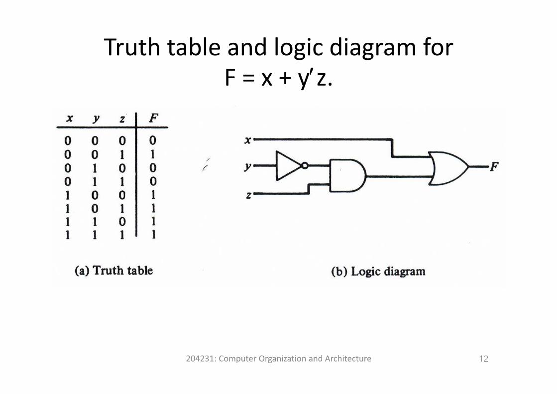
Truth table and logic diagram forF = x + y′z.
204231: Computer Organization and Architecture 12
Boolean ExpressionBoolean Expression
i l i l i• By manipulating a Boolean expression according to Boolean algebra rules, one may obtain a simpler expression that will require fewer gates.
• For example,– AB’ + C’D + AB’ + C’D = AB’ + C’DAB + C D + AB + C D AB + C D– NOR gate ‐> (x+y)’ = x’y’ (DeMorgan’s theorem)NAND gate > (xy)’ = x’+y’ (DeMorgan’s theorem)– NAND gate ‐> (xy) = x +y (DeMorgan s theorem)
204231: Computer Organization and Architecture
13
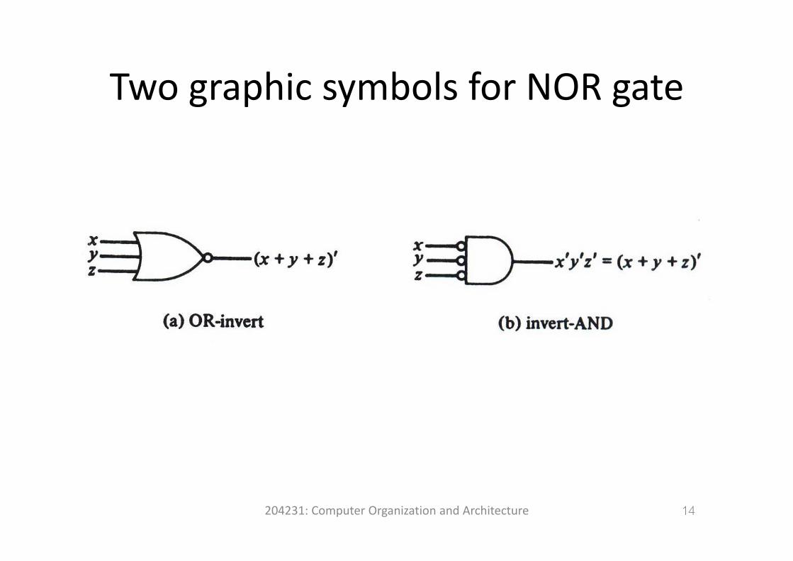
Two graphic symbols for NOR gateTwo graphic symbols for NOR gate
204231: Computer Organization and Architecture 14
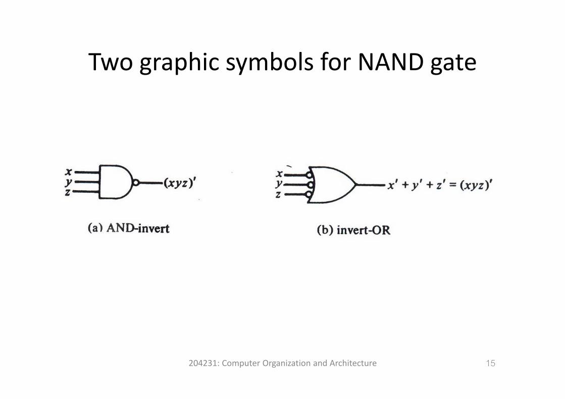
Two graphic symbols for NAND gateTwo graphic symbols for NAND gate
204231: Computer Organization and Architecture 15
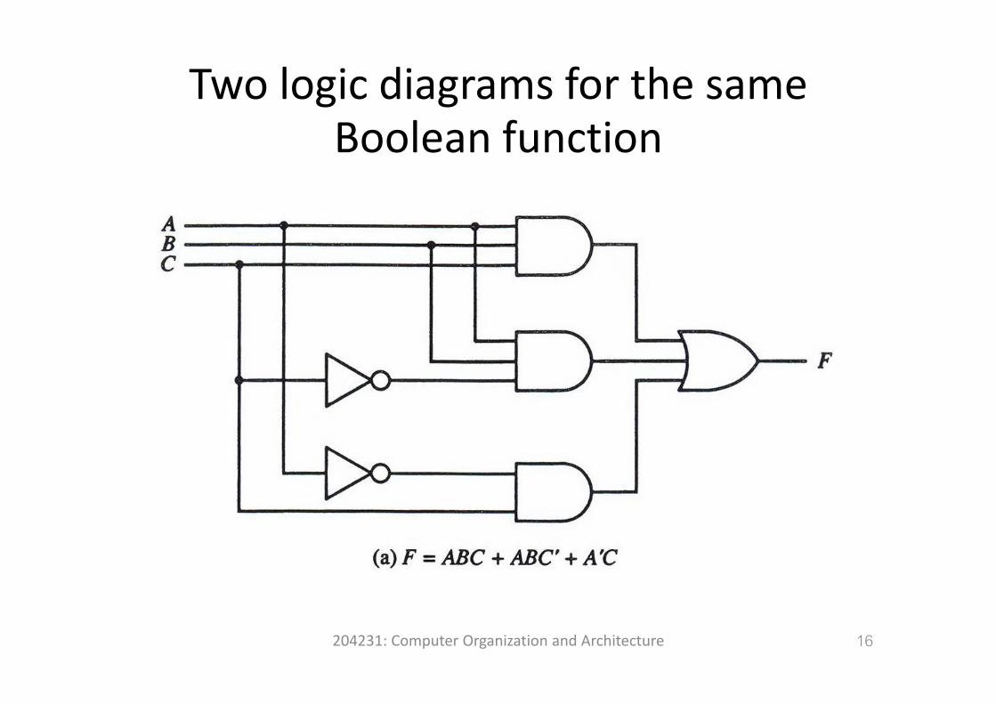
Two logic diagrams for the same Boolean function
204231: Computer Organization and Architecture 16
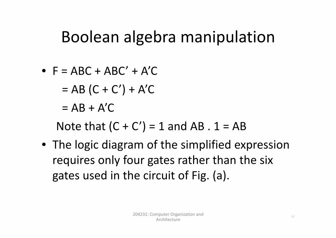
Boolean algebra manipulationBoolean algebra manipulation
• F = ABC + ABC’ + A’C= AB (C + C’) + A’C AB (C + C ) + A C= AB + A’CNote that (C + C’) = 1 and AB . 1 = AB
• The logic diagram of the simplified expressionThe logic diagram of the simplified expression requires only four gates rather than the six t d i th i it f Fi ( )gates used in the circuit of Fig. (a).
204231: Computer Organization and Architecture
17
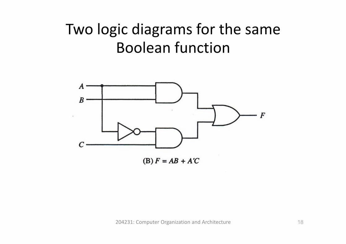
Two logic diagrams for the same Boolean function
204231: Computer Organization and Architecture 18
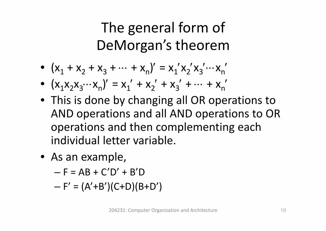
The general form of DeMorgan’s theorem
( )′ ′ ′ ′ ′• (x1 + x2 + x3 + ⋅⋅⋅ + xn)′ = x1′x2′x3′⋅⋅⋅xn′• (x1x2x3⋅⋅⋅xn)′ = x1′ + x2′ + x3′ + ⋅⋅⋅ + xn′( 1 2 3 n) 1 2 3 n
• This is done by changing all OR operations to AND operations and all AND operations to ORAND operations and all AND operations to OR operations and then complementing each individual letter variableindividual letter variable.
• As an example,’ ’ ’– F = AB + C’D’ + B’D
– F’ = (A’+B’)(C+D)(B+D’)
204231: Computer Organization and Architecture 19
Map SimplificationMap Simplification
h i b i lifi d i h b i• The expression may be simplified using the basic relations of Boolean algebra.
• However, this procedure is sometimes difficult because it lacks specific rules for predicting each succeeding step in the manipulative process.
• The map method provides a simple, straightforward procedure for simplifying Boolean expressions.
• The map method is also known as the Karnaugh map or K‐map.
204231: Computer Organization and Architecture
20
Map SimplificationMap Simplification
• The map is a diagram made up of squares, with each square representing one minterm.q p g
• The squares corresponding to minterms that produce 1 for the function are marked by a 1produce 1 for the function are marked by a 1 and the others are marked by a 0 or are left empty.
204231: Computer Organization and Architecture
21
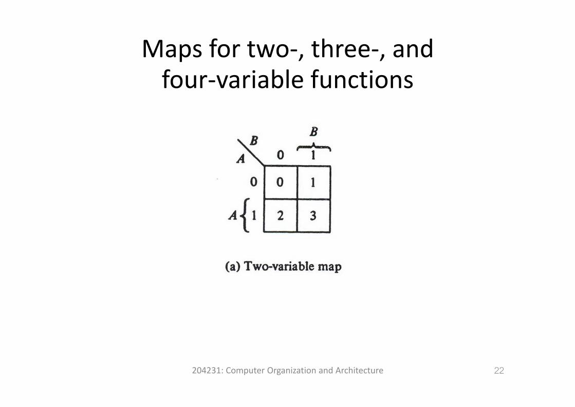
Maps for two‐, three‐, andfour‐variable functions
204231: Computer Organization and Architecture 22
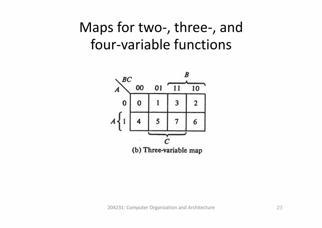
Maps for two‐, three‐, andfour‐variable functions
204231: Computer Organization and Architecture 23
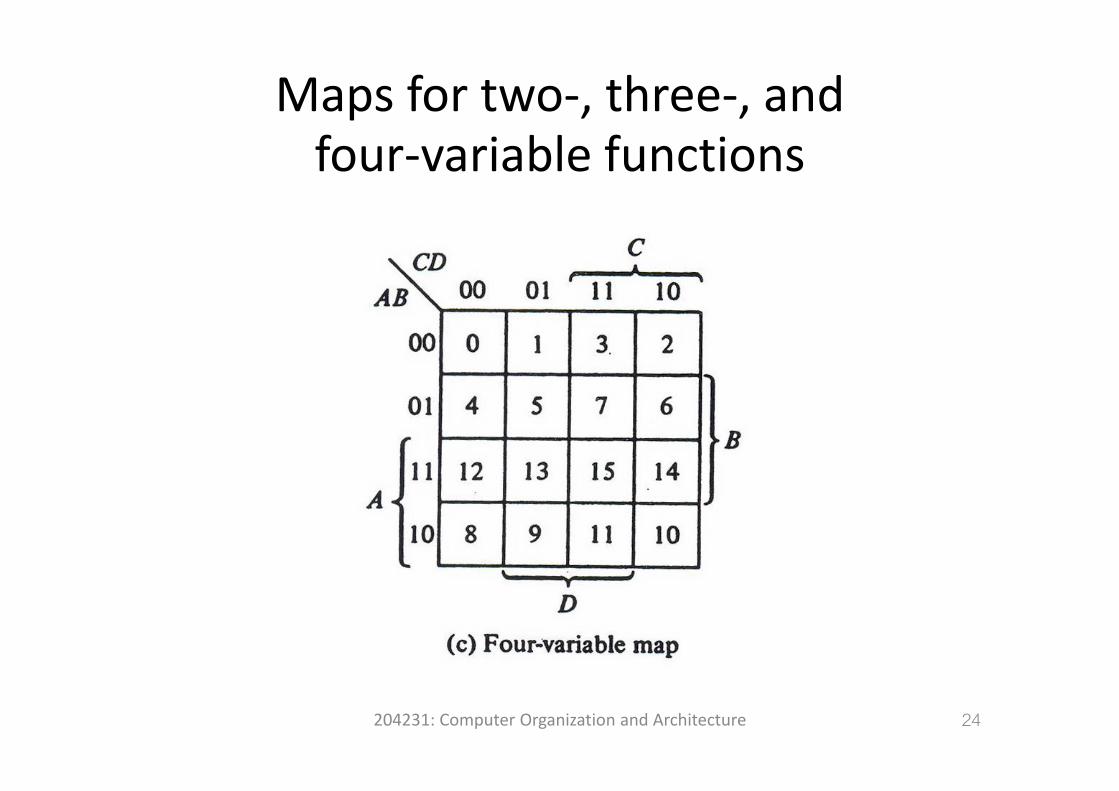
Maps for two‐, three‐, andfour‐variable functions
204231: Computer Organization and Architecture 24
Map SimplificationMap Simplification
i f dj i h• Minterms of adjacent squares in the map are identical except for on variable.
• According to this definition of adjacency, the squares at the extreme ends of the same horizontal row are also to be considered adjacent.
• The same applies to the top and bottom squares of a column.
• As a result, the four corner squares of a map must also be considered to be adjacent.j
204231: Computer Organization and Architecture
25
Map SimplificationMap Simplification
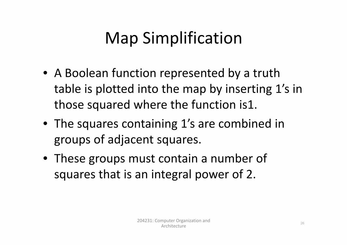
• A Boolean function represented by a truth table is plotted into the map by inserting 1’s in p p y gthose squared where the function is1.
• The squares containing 1’s are combined in• The squares containing 1 s are combined in groups of adjacent squares.
• These groups must contain a number of squares that is an integral power of 2.squares that is an integral power of 2.
204231: Computer Organization and Architecture
26
Map SimplificationMap Simplification
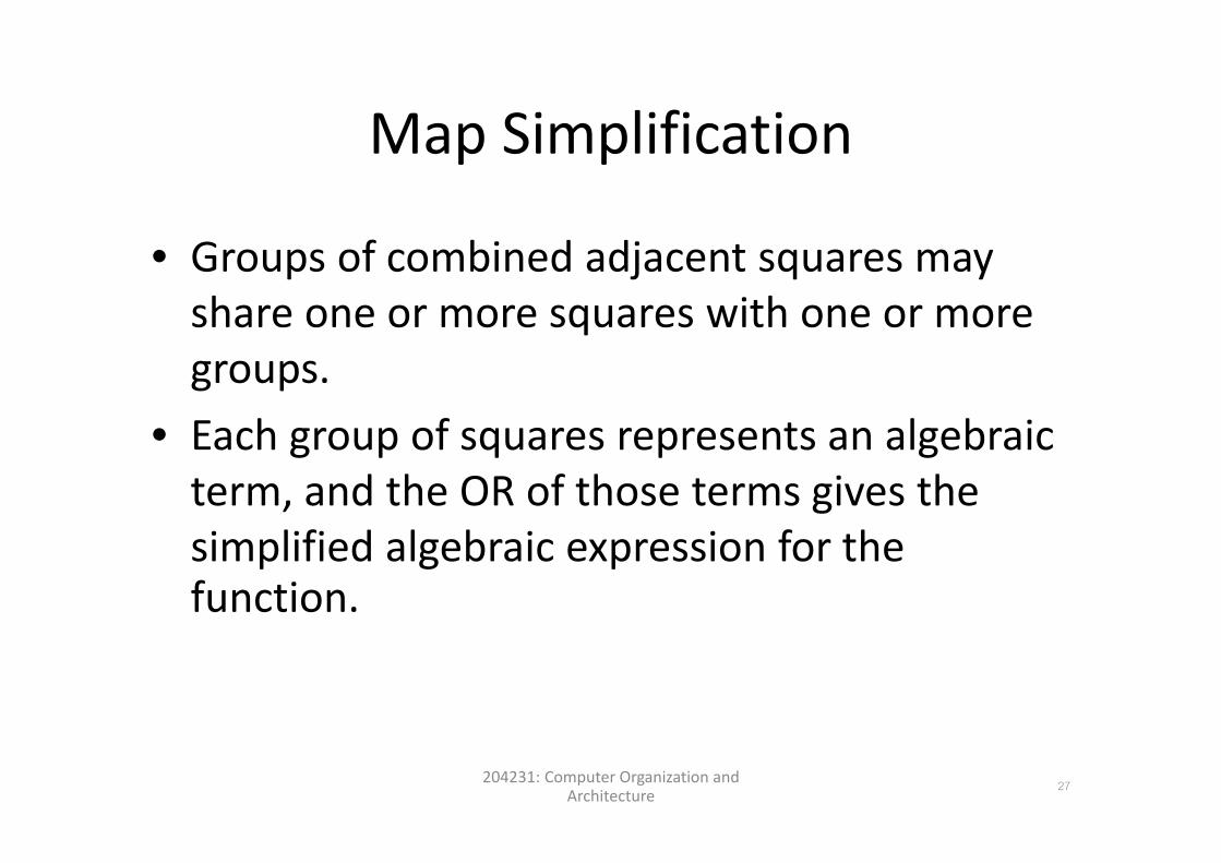
• Groups of combined adjacent squares may share one or more squares with one or more qgroups.
• Each group of squares represents an algebraic• Each group of squares represents an algebraic term, and the OR of those terms gives the
l f l b f hsimplified algebraic expression for the function.
204231: Computer Organization and Architecture
27
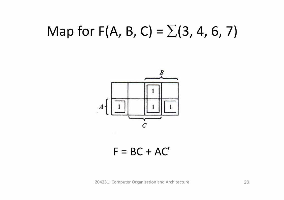
Map for F(A B C) = ∑(3 4 6 7)Map for F(A, B, C) = ∑(3, 4, 6, 7)
F = BC + AC′
204231: Computer Organization and Architecture 28
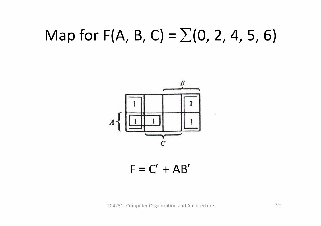
Map for F(A B C) = ∑(0 2 4 5 6)Map for F(A, B, C) = ∑(0, 2, 4, 5, 6)
′ ′F = C′ + AB′
204231: Computer Organization and Architecture 29
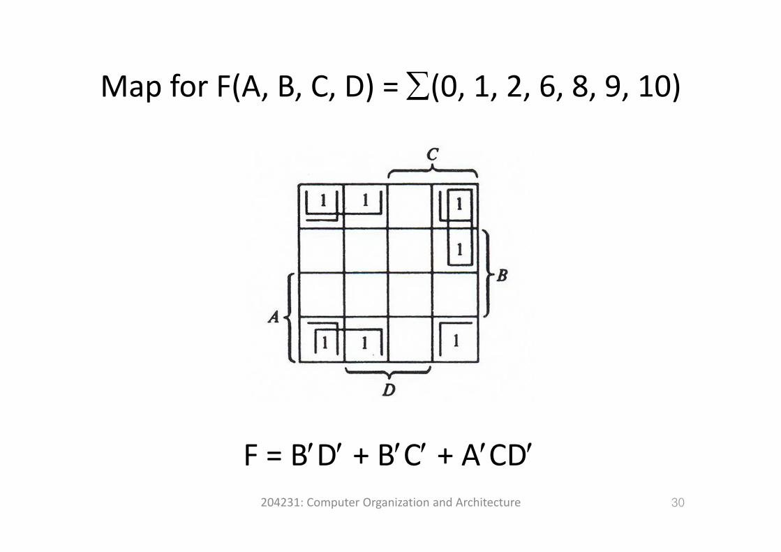
Map for F(A B C D) = ∑(0 1 2 6 8 9 10)Map for F(A, B, C, D) = ∑(0, 1, 2, 6, 8, 9, 10)
F = B′D′ + B′C′ + A′CD′204231: Computer Organization and Architecture 30
F B D B C A CD
Product‐of‐Sums SimplificationProduct‐of‐Sums Simplification
• The 1’s in the map represent the minterms that produce 1 for the function.
• The squares not marked by 1 represent the minterms that produce 0 for the function.minterms that produce 0 for the function.
• If we mark the empty squares with 0’s and bi th i t f dj tcombine them into groups of adjacent squares,
we obtain the complement of the function, F’.• Taking the complement of F’ produces an expression for F in product‐of‐sums form.p p
204231: Computer Organization and Architecture
31

Map for F(A B C) = ∑(0 1 2 5 8 9 10)Map for F(A, B, C) = ∑(0, 1, 2, 5, 8, 9, 10)
Sum‐of‐Product: F = B’D’ + B’C’ + A’C’D
204231: Computer Organization and Architecture 32
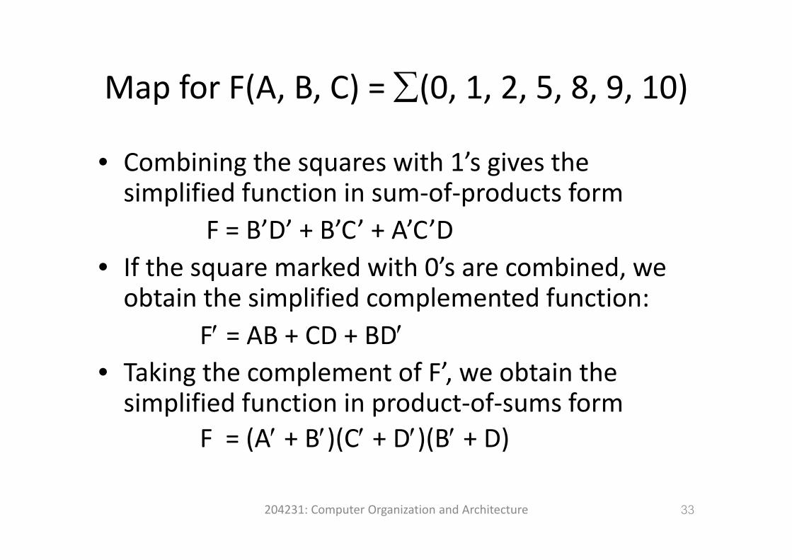
Map for F(A B C) = ∑(0 1 2 5 8 9 10)Map for F(A, B, C) = ∑(0, 1, 2, 5, 8, 9, 10)
C bi i h i h 1’ i h• Combining the squares with 1’s gives the simplified function in sum‐of‐products form
F = B’D’ + B’C’ + A’C’D• If the square marked with 0’s are combined, we qobtain the simplified complemented function:
F′ = AB + CD + BD′F AB CD BD• Taking the complement of F’, we obtain the simplified function in product‐of‐sums formsimplified function in product of sums form
F = (A′ + B′)(C′ + D′)(B′ + D)
204231: Computer Organization and Architecture 33
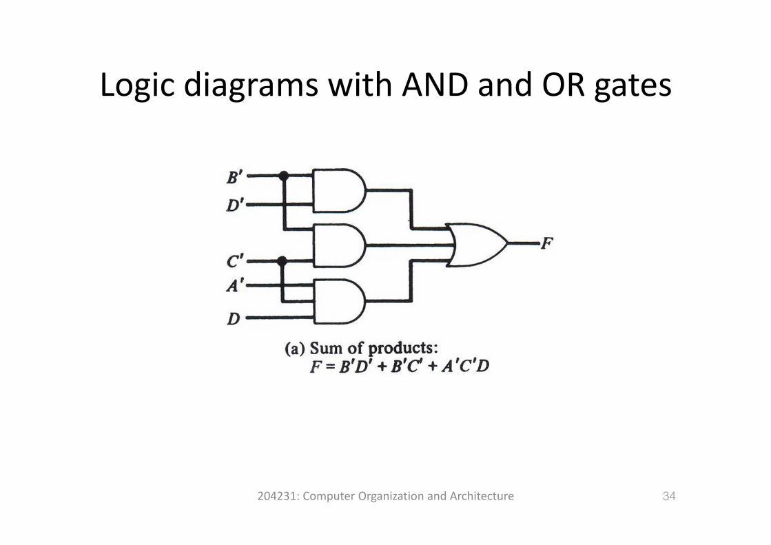
Logic diagrams with AND and OR gatesLogic diagrams with AND and OR gates
204231: Computer Organization and Architecture 34
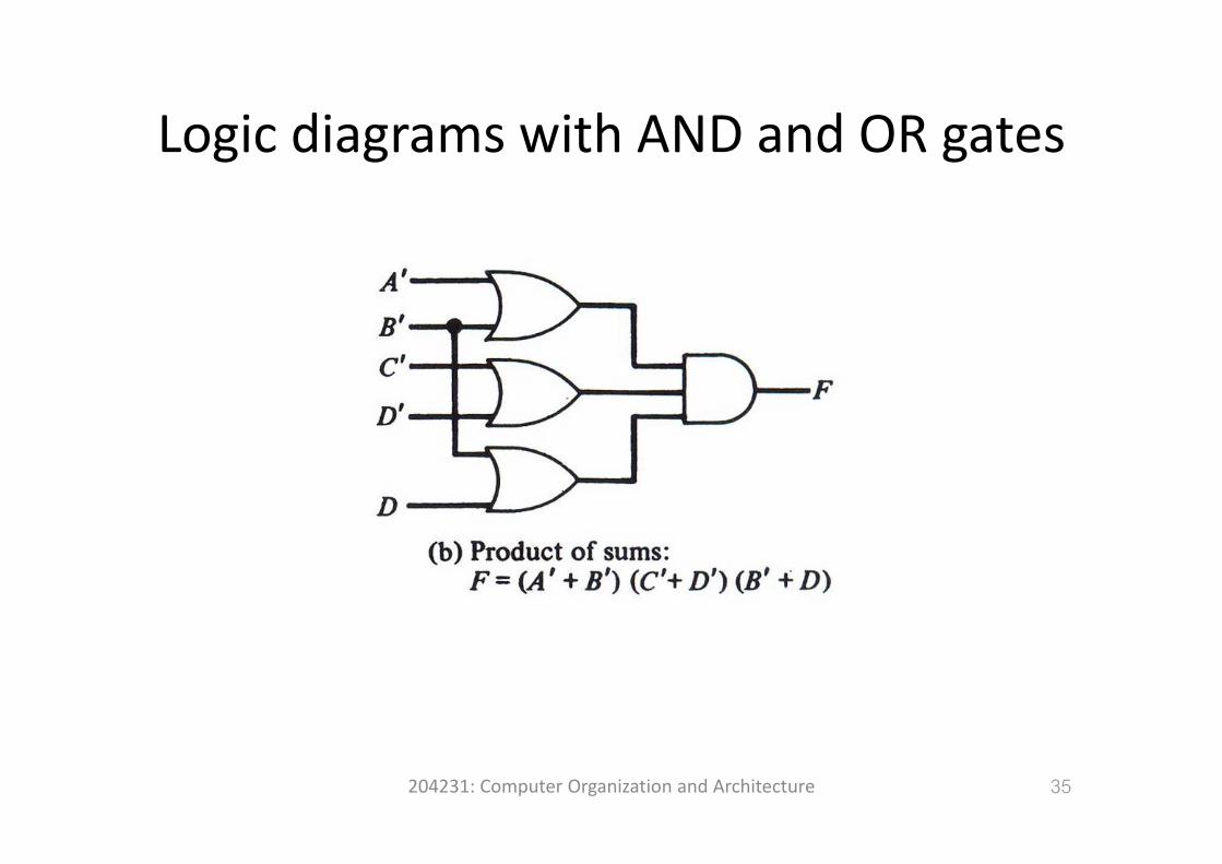
Logic diagrams with AND and OR gatesLogic diagrams with AND and OR gates
204231: Computer Organization and Architecture 35
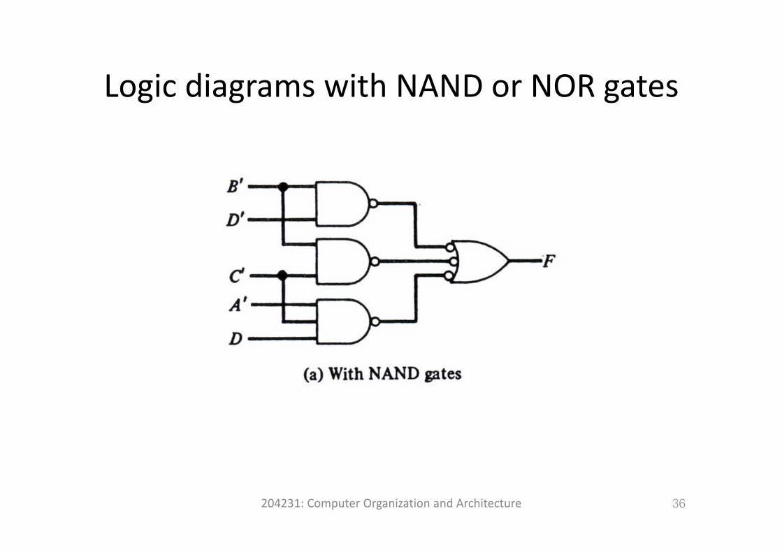
Logic diagrams with NAND or NOR gatesLogic diagrams with NAND or NOR gates
204231: Computer Organization and Architecture 36
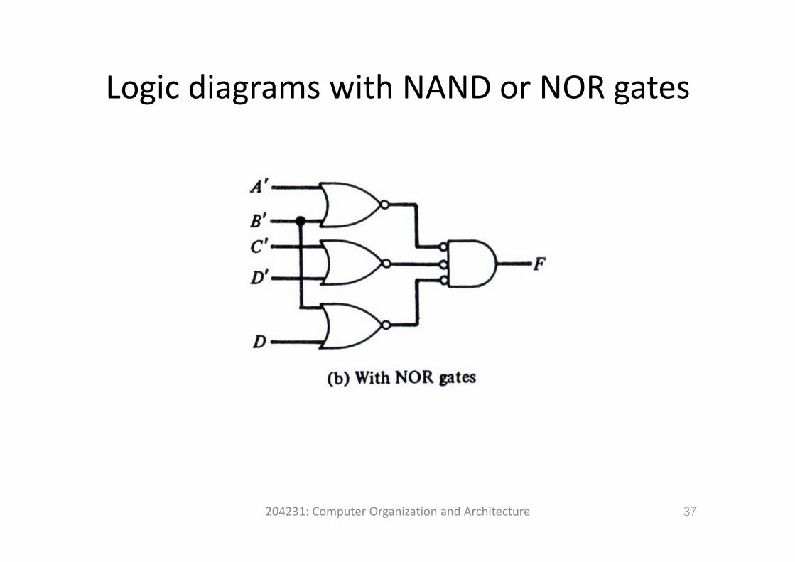
Logic diagrams with NAND or NOR gatesLogic diagrams with NAND or NOR gates
204231: Computer Organization and Architecture 37
Don’t‐Care ConditionsDon t‐Care Conditions
• Since the function may be either 0 or 1, we say that we don’t care what the function output is to be for this minterm.
• Minterms that may produce either 0 or 1 for theMinterms that may produce either 0 or 1 for the function are said to be don’t care conditions and are marked with an x in the mapare marked with an x in the map.
• When choosing adjacent squares for the function i h h ’ b d b i h 0in the map, the x’s may be assumed to be either 0 or 1, whichever gives the simplest expression.
204231: Computer Organization and Architecture
38
Example of map with don’t‐care conditionsExample of map with don t‐care conditions
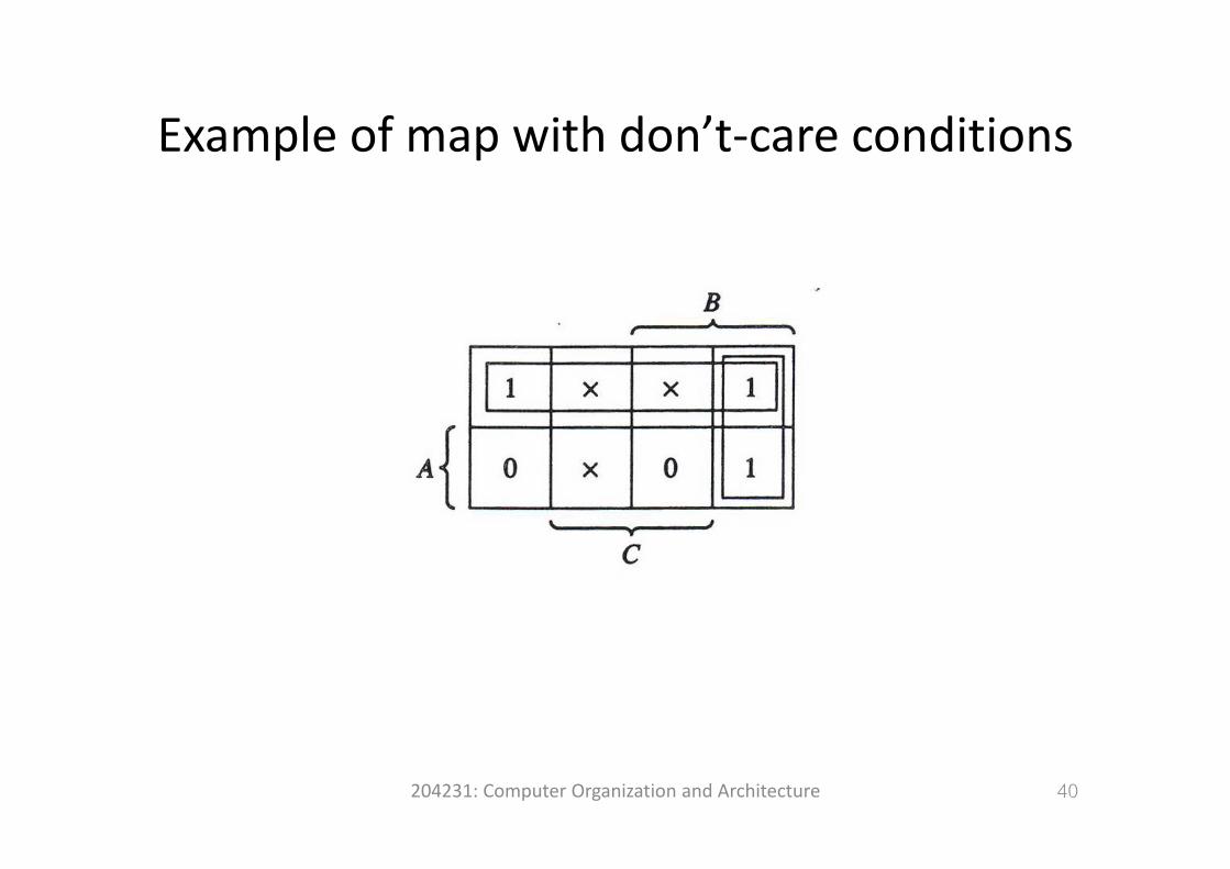
• F(A, B, C) = ∑(0, 2, 6)• d(A, B, C) = ∑(1, 3, 5)d(A, B, C) ∑(1, 3, 5)• The minterms listed with F produce a 1 for the f ifunction.
• The don’t‐care minterms listed with d may yproduce either a 0 or a 1 for the function.
204231: Computer Organization and Architecture 39
Example of map with don’t‐care conditionsExample of map with don t‐care conditions
204231: Computer Organization and Architecture 40
Example of map with don’t‐care conditionsExample of map with don t‐care conditions
• The simplified expression is F = A′ + BC′• Note that don’t‐care minterm 5 was notNote that don t care minterm 5 was not included because it does not contribute to the simplification of the expressionsimplification of the expression.
• Thus this expression represent the Boolean function F(A, B, C) = ∑(0, 1, 2, 3, 6)
204231: Computer Organization and Architecture 41
ReferenceReference
• M. Moris Mano, Computer System Architecture, 3rd ed. NJ: Prentice Hall, 1992.
204231: Computer Organization and Architecture 42