Embed Size (px)
Citation preview

Computer Architecture
First: a fake one

The Pep/8 Computer
• Simulated computer system
• Has features in common with many real architectures
• Illustrates fundamental concepts that apply to most systems

Pep/8 “hardware” components
• CPU
• Main memory
• I/O devices
• Bus

Pep/8 CPU
• “Electronics” that comprise the Pep/8 instruction set:– ALU– Control unit
• Registers: specialized high-speed memory locations

Pep/8 registers
• Status register (NZVC) contains 4 bits; values set by results of various operations:– N bit: set when a result is negative– Z bit: set when a result is 0– V bit: set when an overflow occurs– C bit: set when a carry occurs
• Accumulator (A): 16-bit register; contains result of an operation

Pep/8 registers that communicate with main memory
• Index (X) used for accessing array elements; 16 bits
• Program Counter (PC) is used to keep track of current instruction; 16 bits
• Instruction Register (IR): 24-bit register that holds the current instruction
• Stack Pointer (SP): keeps track of runtime stack; 16 bits

Main memory
• Aka core memory• 65,536 8-bit bytes, addressed from 0000
(top address) to FFFF (bottom address)• Word: specific # of bytes, usual working
storage unit size– Pep/8 has 16-bit word; this accounts for the
size of most of the registers– Address of a word is the lower (in value) of
the two bytes

Addresses vs. Contents
• Both are 16 bits, but address never means data, and content never means address (unless we’re talking about pointers, which we’re not, for now)
• The bit sequence stored in a word of memory could be interpreted as an instruction or as one of several types of data – as far as memory is concerned, it’s just bits

Input devices
• Pep/8 simulates 2:– Keyboard– File
• In a particular program, you can use either, but not both

Output devices
• Same sort of rules as input; 2 supported, but only one at a time:– Screen– Text file

• All data flow through memory en route to and from CPU:Input Memory CPU
CPU Memory Output
• Control signals originate in the CPU; processor controls all other parts of computer
Flow of Data & Control

Instructions
• In general, the instruction set is wired into the CPU:– Varies among manufacturers– May also vary within a specific manufacturer’s set of
platforms (e.g. IBM)
• Pep/8 Instruction set– 32 instructions; 1 or 2-part– All instructions have a 1-byte instruction specifier; 2-
part instructions have this, plus a 16-bit operand specifier

Pep/8 Instruction Specifier Format
• Each instruction specifier is composed of:– 4-bit opcode: determines which instruction will
be executed– 1-bit register specifier: determines whether
the instruction affects the accumulator (O=A) or index register (1=X)
– 3-bit addressing mode specifier (ignored if instruction is unary)

Pep/8 Addressing Modes
• Immediate: operand specifier contains operand itself
• Direct: operand specifier is address of memory word containing operand
• Indirect: operand specifier is address of memory address containing address of operand
• Stack relative: operand specifier contains offset to add to SP - specifies memory address
• and 4 others

Character I/O
• I/O devices based on ASCII set
• Interpretation/encoding of data occurs in I/O devices, not memory

Pep/8 op codes
• The next several slides introduce some of the Pep/8 op codes
• The instructions described either use no addressing, or direct addressing mode:– The operand specifier contains the memory address
of the operand– Memory is treated as an array, with the number in the
operand specifier acting as the array address
• We will look at some instructions that use other addressing modes later on

Op code 0000
• Stop execution:– Halts execution of current program– Ignores all bits except op code– Hex version is 0x where x is any value < 8
(but is most often written 00)

Data movement instructions
• 1100: memory to register transfer (LOAD)– Loads 1 word (2 bytes) from specified
memory to specified register– Register involved is A or X– affects N & Z bits
• 1110: register to memory transfer (STORE)– Stores content of A or X to specified memory
location

LOAD examples
hex instruction: C1004Abinary expansion:1100 0001 0000 0000 0100 1010
op code
register: 0 means A, 1 means X
addressing mode: 1 means direct
address to read from
hex instruction: C97F43
1100 1001Load from address 7F43 to X register

Effects of LOAD instruction on status bits
• If the data contained at the source address is negative, N bit is set (to 1); if not, it is cleared (to 0)
• If the data is 0, the Z bit is set; otherwise, it is cleared

STORE instruction: examples
Hex code: E9004Abinary: 1110 1001 0000 0000 0100 1010opcode: STOREUse register X
with direct addressing
Write data from index register to address 004A
Hex code: E1621CFirst 8 bits: 1110 0001opcode: STORE direct addressing
register A
Write data from accumulator to address 621C

Byte-size data transfer: variations on LOAD and STORE
• 1101: load byte to register– Loads data into right (lower) half of A or X– Leave upper (left) half unchanged
• 1111: store byte to memory (from register): stores lower half of A or X to specified byte of memory
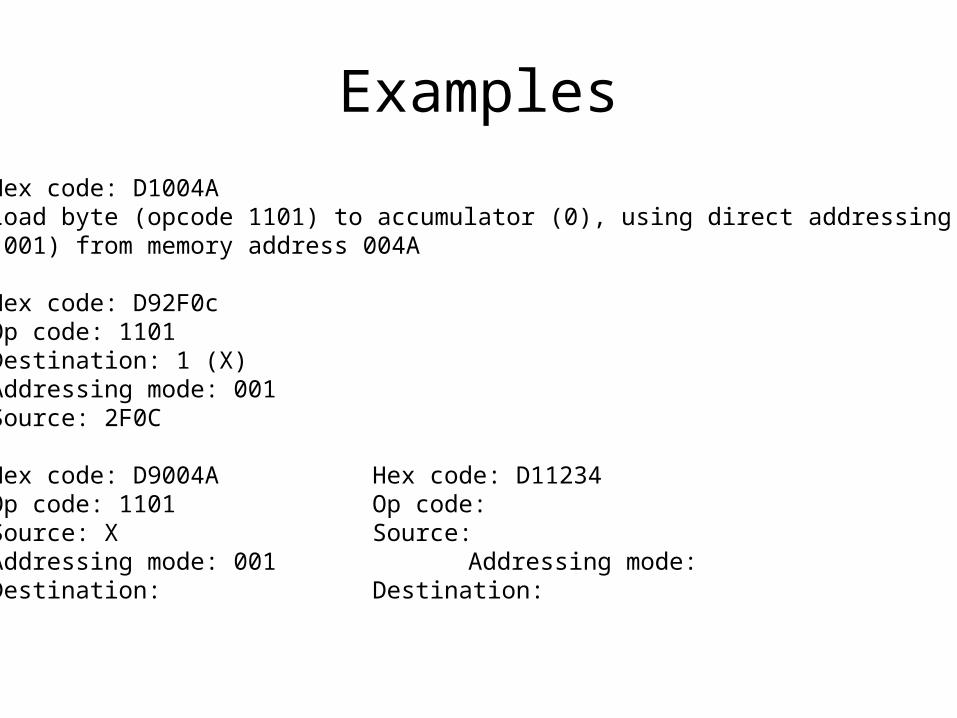
Examples
Hex code: D1004ALoad byte (opcode 1101) to accumulator (0), using direct addressing(001) from memory address 004A
Hex code: D92F0cOp code: 1101Destination: 1 (X)Addressing mode: 001Source: 2F0C
Hex code: D9004A Hex code: D11234Op code: 1101 Op code:Source: X Source:Addressing mode: 001 Addressing mode:Destination: Destination:

Arithmetic operations: ADD
• 0111: Add operand to register
• Examples:– 71004A: add value stored at 004A to
accumulator• Opcode: 0111• Register: 0 (A)• Mode: 01 (direct)
– 7922FA: add value at 22FA to X

Effects of ADD on status bits:
• If sum is negative, N set to 1; otherwise, cleared to 0
• If sum is 0, sets Z; clears otherwise
• If overflow occurs, V is set, else cleared
• If carry from MSB, C set, else cleared

Arithmetic operations: SUB
• 1000: subtract from register– Value from specified address subtracted from
specified register (A or X)
• Examples:– 89004A: subtract value in 004A from X
• Opcode: 00100• Register: 1• Mode: 01
– 8102B3: subtract value in 02B3 from A

Effects of SUB on status bits
• N: set if result (stored in register) negative, cleared if not
• Z: set if result 0, cleared if not
• V: set if overflow
• C: set if borrow in MSB

Shift operations
• 0001 110r ASL (shift register left)
• 0001 111r ASR (shift right)
• Shift is a unary operation: affects register only
• No addressing mode used
• Examples:– 1C performs ASL on A– 1F performs ASR on X