Embed Size (px)
DESCRIPTION
The International Institute for Science, Technology and Education (IISTE). Science, Technology and Medicine Journals Call for Academic Manuscripts
Citation preview
Innovative Systems Design and Engineering www.iiste.org
ISSN 2222-1727 (Paper) ISSN 2222-2871 (Online)
Vol.5, No.7, 2014
12
Computer Aided Structural Analysis of Axle Tilting Effect on
Tractor Front Axle Support
Aduloju, Sunday Christopher*,
National Engineering Design Development Institute, Nnewi, Anambra State, Nigeria
Email: [email protected]
Mgbemena, Chinedum Ogonna,
Department of Mechanical Engineering, Federal University of Petroleum Resources, Effurun, Delta State,
Nigeria
Email: [email protected]
Ebhota, Williams Saturday,
National Engineering Design Development Institute, Nnewi, Anambra State, Nigeria
Email:[email protected]
Bolarinwa, Gabriel Oladeji
National Engineering Design Development Institute, Nnewi, Anambra State, Nigeria
Email:[email protected]
Abstract
Studies were carried out to determine the worst load case scenario on Ursus 3512 60hp Tractor Front Axle
Support using MATLAB to analyze 36 load cases. The worst load case scenario was found to be the dynamic
load case of 3g with wheel force of 9810N and axle angle of 120.The load on the Pivot hole of the tractor support
was found to be 56057N. The component was modelled using Pro-Engineer (now CREO Elements). The
structural analysis of component was done with the worst load case using Pro-Mechanica. The working or design
stress was generated from the analysis within best convergence limit. The estimated maximum limiting yield
stress estimated as von Mises stress of the front axle support is 88 N/mm2. The factor of safety for the
component design was calculated to be 2.84 which were lower than the recommended value of 5.5 to 6.5. The
Minimum allowable stress and Maximum allowable stress for the Component design would be 484N/mm2 and
572N/mm2.
Keywords: Tractor; structural analysis; Matlab; Pro-Engineer; Pro-Mechanica; Factor of Safety; Front Axle
support.
1. Introduction
The tractor is an off road vehicle employed for use in farming, haulage, transportation, heavy earth moving etc.
The tractor has a front axle which supports the whole body at the front which is known as ‘dead axle’. The front
axle and its supports encounter the worst load conditions during operations.
Several studies have been carried out by researchers on Agricultural Tractors. Tests, analysis and design
modification have been carried out by field tests and more recently by Computer Aided Engineering Approach.
Späth [1] investigated the loads, which acts on a tractor chassis. For this purpose, an instrument wheel was
designed and built which allows the wheel load, the draft and lateral force at a tractor rear wheel to be measured
reliably and with sufficient precision. Experiments were carried out including driving over a ramp and axle loads
were recorded.
The Institute of Agricultural Machinery of Technical University Munich [2] in the year 1999 did some studies to
investigate the loads on the tractor body. The goals was to calculate the fatigue life of the tractor components. A
Innovative Systems Design and Engineering www.iiste.org
ISSN 2222-1727 (Paper) ISSN 2222-2871 (Online)
Vol.5, No.7, 2014
13
tractor was equipped to measure the loads on the tractor axles and the loads on the three point hitch. The loads
while working on the field and driving on the ISO-tracks were measured. A load spectrum was processed from
the load time history by using rainfall cycle method. Finally, the total fatigue damage for the tractor components
was calculated, considering damage accumulation hypothesis defined by Miner [3].
Yahya [4] developed an instrument and sensor system for an agricultural tractor. The system was constructed on
the tractor and was capable of recording information for drawbar pull force, drive wheel torque and both vertical
and horizontal forces at the 3-point hitches of the tractor implement. The data acquisition system utilized a
designed draw bar pull transducer to measure horizontal pull at tractor drawbar point, wheel torque transducers
to measure the torque at both tractor rear wheels, and a 3-point auto hitch dynamometer to measure the
horizontal and vertical forces on the implement behind the tractor.
Al – Janobi et al. [5] developed a data acquisition system to measure various tractor performance parameters
such as wheel forces, three-point linkage forces, drawbar force, PTO torque and ground speed. An electronic
circuit was designed and fabricated to provide exact angular position measurement of the clevis bolts in the
tractor wheels at any travel speed and scanning rate of the data logger used. This measurement was found to be
more accurate and reliable as compared to the measurement by the marker pulse of the optical shaft encoder,
which is dependent on the data logger scanning time. The force measurement from the clevis bolts combined
with the angular position measurement gives the total horizontal and the vertical components of forces on the
revolving wheel. An onboard data logger was used to sample signals from the various transducers as well as the
angular position measurement circuit in the system. The system was field tested for its performance and found to
be accurate and reliable in measurement of tractor performance parameters.
Balasubramanian et al. [6] developed a data acquisition system to measure vibration data from an agricultural
tractor. Accelerometers were mounted on the front and rear axle and on the driver’s seat. An ultra sound ground
speed sensor was used to monitor velocity. These sensors were connected to a National Instruments Modular
Signal Conditioning Carrier (MSCC). Lab VIEW was employed to provide Graphical User Interface (GUI) to
the data acquisition system; manage data acquisition and store ground speed and accelerometer signals. An
obstacle course was constructed to stimulate rough field terrain. The tractor was driven through the course at
prescribed velocities while data was created to mark the obstacles and provide a ground of old obstacles.
Correlations could then be made between the known obstacle of varying magnitude and the measured shock and
vibration events as a function of ground speed.
Redkar [7] did a study to prove that a good correlation exists between Virtual Simulation and Physical behaviour
of machine components. A nonlinear behaviour of Tractor Front Axle was simulated using Abacus CAE, well
known software for nonlinear simulation. Non linearity was simulated by putting the material nonlinear data in
the material stress strain curve.
Mahanty et al. [8] in their study at Tata Industries employed CAE approach to analyze a new design of the front
axle of an agricultural tractor. The geometric models for the existing design and proposed designs were created
and imported into ANSYS. The proposed designs were evaluated for selected worst case scenarios of the tractor.
Based on the finite element analysis results, redesign was carried out for the front axle.
Koyuncu [9] in his study did analysis of the FE model of the front axle support. He implemented for the load
cases that are considered during the design of the front axle support. A set of load cases for the agricultural
tractor front axle supports was selected by surveying the literature and consulting the designers of Erkunt
Agricultural Machinery.
In this study, the cause of fracture in front axle support of tractors was detected using Computer Aided
Engineering. Pro-Engineer was used to model the component; MatLab was used to analyse the forces and finally
Innovative Systems Design and Engineering www.iiste.org
ISSN 2222-1727 (Paper) ISSN 2222-2871 (Online)
Vol.5, No.7, 2014
14
Pro-Mechanica was used to perform FEA simulation of the fracture. This research work is focused on the
Analysis of the Front Axle support of Ursus 3512 60hp agricultural tractor.
2. Methodology
2.1 Component Modelling
The dimensions of Ursus 3512 60hp tractor front axle support were measured and recorded. The dimensions
were used in modelling the component in a virtual environment. Pro-Engineer software was used to achieve this
purpose. The solid subtype – part type modelling environment was used. The component was therefore modelled
as a .prt file.
2.2 Component Properties
The front axle support design was manufactured from GG-25, gray cast iron. Some analysis has been carried on
the said material by Koyuncu [9]. GG-25 cast iron is a brittle material. The evaluations were done considering its
ultimate tensile strength (uniaxial tension strength) value, which is 250MPa [9].
Table 1 The mechanical properties of GG-25 Cast iron
Material Properties Value
Modulus of Elasticity 120000MPa
Poisson’s Ratio 0.23
Ultimate Tensile Strength 250MPa
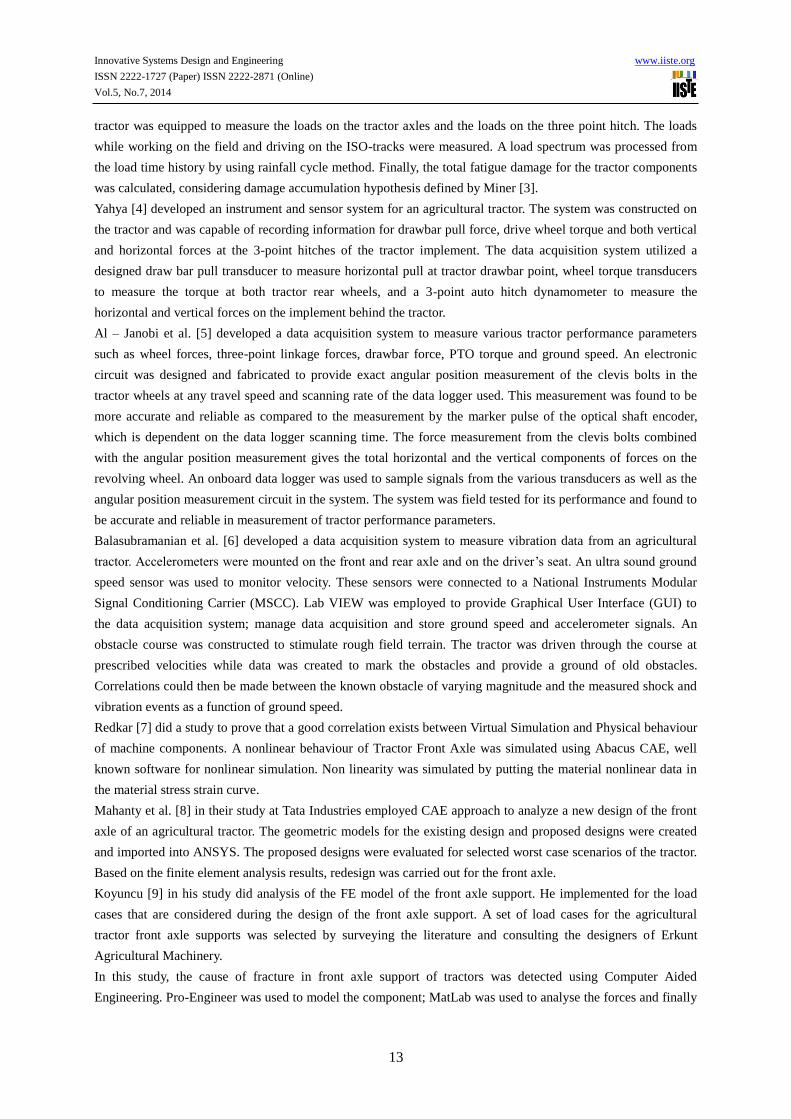
Figure 1 The Failed Tractor Front Axle Support
Innovative Systems Design and Engineering www.iiste.org
ISSN 2222-1727 (Paper) ISSN 2222-2871 (Online)
Vol.5, No.7, 2014
15
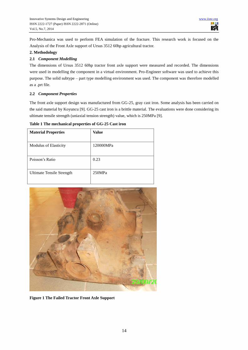
Figure 2 The modelled Tractor front Axle Support
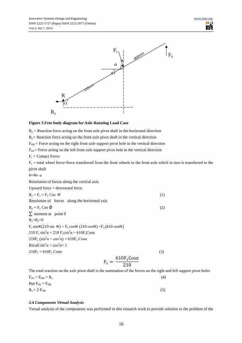
2.3 Analysis of Forces
The design of the Tractor support by tractor companies has been done by bearing in mind the worst case scenario.
The worst case scenario used in former designs was the load case during fatigue (3g loading case). This work
therefore considers the possibility of a worst case that occurs when the front axle and front axle support make
contact as a result of the 120 maximum rotation of the front axle during fatigue (contact load). A new free body
diagram was developed from the initial diagram. This free body diagram includes the rotation of the front axle
during the fatigue loads. Therefore a contact force (Fc) is applied to the front axle support on the contact location.
The force components on the contact location and pivot shaft holes was calculated from the free body diagram of
the front axle as presented in figure 3. The effect of the angular placement of the front axle support was
evaluated by considering 36 load cases. The contact force and the reactions were calculated. The static loads and
fatigue loads were analyzed as 1g load case and 3g load case. The front axle makes contact with the front axle
support at 210mm length from the pivoting shaft and 400mm to the wheel. The design of the axle placement was
done such that it is not being constrained by front axle support.
Innovative Systems Design and Engineering www.iiste.org
ISSN 2222-1727 (Paper) ISSN 2222-2871 (Online)
Vol.5, No.7, 2014
16
Figure 3 Free body diagram for Axle-Rotating Load Case
Ry = Reaction force acting on the front axle pivot shaft in the horizontal direction
Rz = Reaction force acting on the front axle pivot shaft in the vertical direction
FHR = Force acting on the right front axle support pivot hole in the vertical direction
FHL= Force acting on the left front axle support pivot hole in the vertical direction
Fc = Contact Force
Fz = total wheel force=force transferred from the front wheels to the front axle which in turn is transferred to the
pivot shaft
θ=90- α
Resolution of forces along the vertical axis
Upward force = downward force
Rz + Fz = Fc Cos ∝ (1)
Resolution of forces along the horizontal axis
Ry = Fc Cos ∅ (2)
∑ moment at point 0
Ry=Rz=0
Fc sin∝(210 sin ∝) + Fc cos∝ (210 cos∝) =Fz (610 cos∝)
210 Fc sin2α + 210 Fccos
2α = 610FzCosα
210Fc (sin2α + cos
2α) = 610Fz Cosα
Recall sin2α + cos
2α= 1
210Fc = 610Fz Cosα (3)
Fc = 610FzCosα
210
The total reaction on the axle pivot shaft is the summation of the forces on the right and left support pivot holes
FHL + FHR = Rz (4)
But FHL = FHR
Rz = 2 FHR (5)
2.4 Components Virtual Analysis
Virtual analysis of the components was performed in this research work to provide solution to the problem of the
Fc
α
Fz α
Ry
Rz
α O
θ
Innovative Systems Design and Engineering www.iiste.org
ISSN 2222-1727 (Paper) ISSN 2222-2871 (Online)
Vol.5, No.7, 2014
17
tractor front axle failure using Matlab, Pro-Engineer and pro-Mechanica. Matlab was used to calculate and
resolve the forces acting on the front axle support when the axle tilts at the angle of 1 to the maximum angle of 12
degrees. This is done to actually get the worst load case scenario.
Pro-Mechanica was used to simulate the stress variation, displacement and strains across the component. The
software uses a finite element method in finding solution to problems. The properties of GG cast iron were
assigned to the virtual component. The properties fed include the young modulus, the poisons ratio, the yield
strength and density of the component.
In virtual analysis, attempts were made carefully to simulate the component to near real life case. Pro-Mechanica
was very useful especially in the area of constraint definition. Since the component was bolted to other
components/body the component constraint tool was used to simulate the bolt and nut connection experienced by
the component at all necessary points.
2.5 Load Cases
The component was simulated under various load cases to determine the maximum stress and displacements that
occur at various load cases of interest. The load cases of interests include:
i. Wheel reaction load case---------------9810N
ii. The 3g load case(fatigue)-----------------29430N
iii. The Axle-Rotating-3g---------------------56057N
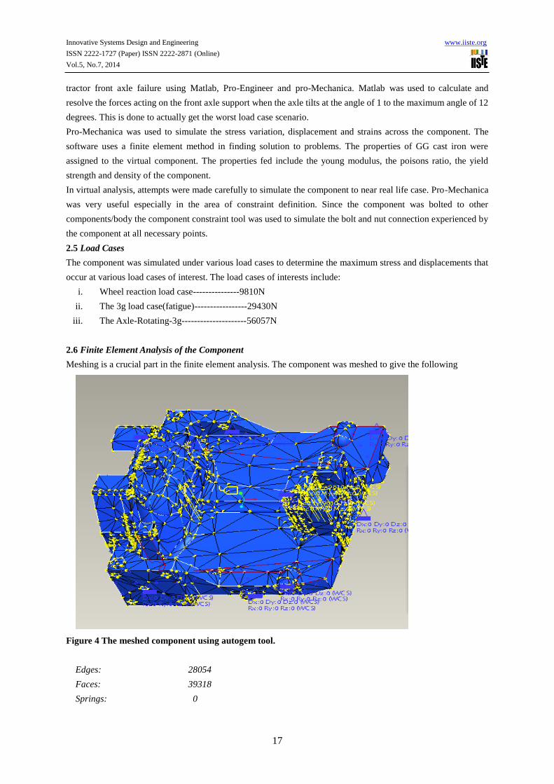
2.6 Finite Element Analysis of the Component
Meshing is a crucial part in the finite element analysis. The component was meshed to give the following
Figure 4 The meshed component using autogem tool.
Edges: 28054
Faces: 39318
Springs: 0
Innovative Systems Design and Engineering www.iiste.org
ISSN 2222-1727 (Paper) ISSN 2222-2871 (Online)
Vol.5, No.7, 2014
18
Masses: 0
Beams: 0
Shells: 0
Solids: 17078
Nodes: 5801
Elements: 17078
The convergence method used is Multi-pass Adaptive method with a polynomial order of 9 and percentage
convergence limit of 10%. The analysis is also designed to converge on local displacement, Global Strain energy
and global RMS stress.
2.7 Factor of Safety
For cast iron like other brittle materials, the yield point is not well defined as for ductile materials. Therefore the
factor of safety for brittle materials is based on ultimate tensile stress. For this case a factor of Safety of 5-6 is
recommended [10].
Factor of safety = ultimate tensile stress
Working or design stress (6)
3. Results and Discussions
3.1 Computer Aided Analysis of Forces
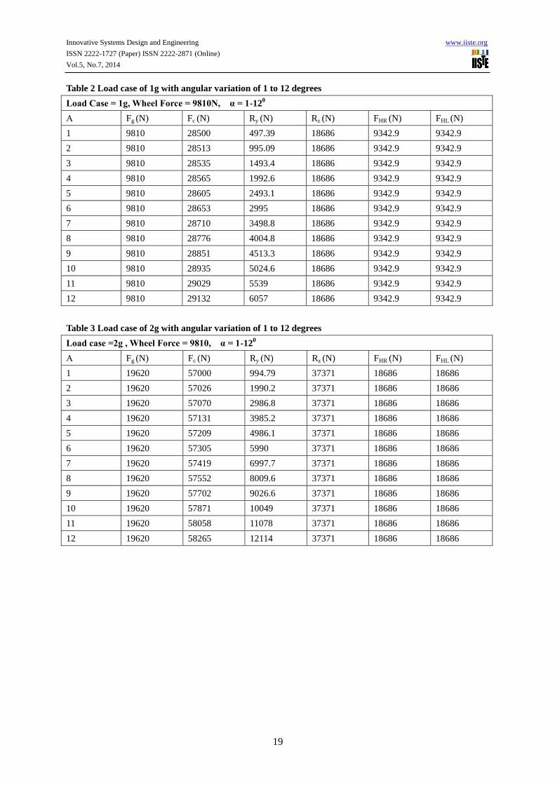
Table 2 shows the effect of angular variation on the forces and reactions on the axle support for static load case.
For θ = 1, the minimum value for Fc and Ry as 28,500N and 497.39N.For θ =12, the maximum value for Fc and
Ry as 29,132N and 6,057N.For θ=1-12, there was consistent value of 18,686N and force components FHL and
FHR as 9342.9N.The initial value for Fg is equal to 9810N, Fc equals to 28500N, Ry equal to 497.39N and Rz
equal to 18686N. The variations of the angle affected only Fc and Ry with Rz being constant all through the
angular variation. An increase in θ leads to an increase in Fc and Ry.
Table 3 shows the effect of angular variation on the forces and reactions on the axle support for a load case of 2g.
For θ = 1, the minimum value for Fc and Ry as 57,000N and 994.79N.For θ =12, the maximum value for Fc and
Ry as 58,265N and 12,114N.For θ=1-12, there was consistent value of Rz as 37,371N and force components FHL
and FHR as 18,686N.The initial value for Fg is equal to 19620N, Fc equals to 57000N, Ry equal to 994.79N and
Rz equal to 37371N. The variation of the angle affected only Fc and Ry with Rz being constant all through the
angular variation. An increase in θ leads to an increase in Fc and Ry.
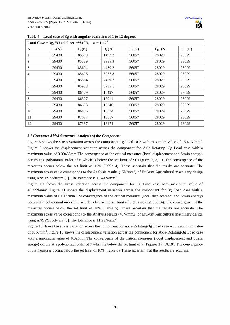
Table 4 shows the effect of angular variation on the forces and reactions on the axle support for dynamic load
case. For θ = 1, the minimum value for Fc and Ry as 85,500N and 1,492.2N. For θ=12, the maximum value for
Fc and Ry as 87,397N and 18,171N. For θ=1-12, there was consistent value of 6057N and force components FHL
and FHR as 28029N. The initial value for Fg is equal to 29430N, Fc equals to 85,500N, Ry equal to 1492.2N and
Rz equal to 56057N. The variation of the angle affected only Fc and Ry with Rz being constant all through the
angular variation. An increase in θ leads to an increase in Fc and Ry. A total of 36 load cases have been
considered in this research work and the worst case scenario is the load case of 3g with wheel force of 9810N
axle angle of 120. This worst case has Ry value of 18,171N and Rz value of 56057N.
Innovative Systems Design and Engineering www.iiste.org
ISSN 2222-1727 (Paper) ISSN 2222-2871 (Online)
Vol.5, No.7, 2014
19
Table 2 Load case of 1g with angular variation of 1 to 12 degrees
Load Case = 1g, Wheel Force = 9810N, α = 1-120
Α Fg (N) Fc (N) Ry (N) Rz (N) FHR (N) FHL (N)
1 9810 28500 497.39 18686 9342.9 9342.9
2 9810 28513 995.09 18686 9342.9 9342.9
3 9810 28535 1493.4 18686 9342.9 9342.9
4 9810 28565 1992.6 18686 9342.9 9342.9
5 9810 28605 2493.1 18686 9342.9 9342.9
6 9810 28653 2995 18686 9342.9 9342.9
7 9810 28710 3498.8 18686 9342.9 9342.9
8 9810 28776 4004.8 18686 9342.9 9342.9
9 9810 28851 4513.3 18686 9342.9 9342.9
10 9810 28935 5024.6 18686 9342.9 9342.9
11 9810 29029 5539 18686 9342.9 9342.9
12 9810 29132 6057 18686 9342.9 9342.9
Table 3 Load case of 2g with angular variation of 1 to 12 degrees
Load case =2g , Wheel Force = 9810, α = 1-120
Α Fg (N) Fc (N) Ry (N) Rz (N) FHR (N) FHL (N)
1 19620 57000 994.79 37371 18686 18686
2 19620 57026 1990.2 37371 18686 18686
3 19620 57070 2986.8 37371 18686 18686
4 19620 57131 3985.2 37371 18686 18686
5 19620 57209 4986.1 37371 18686 18686
6 19620 57305 5990 37371 18686 18686
7 19620 57419 6997.7 37371 18686 18686
8 19620 57552 8009.6 37371 18686 18686
9 19620 57702 9026.6 37371 18686 18686
10 19620 57871 10049 37371 18686 18686
11 19620 58058 11078 37371 18686 18686
12 19620 58265 12114 37371 18686 18686
Innovative Systems Design and Engineering www.iiste.org
ISSN 2222-1727 (Paper) ISSN 2222-2871 (Online)
Vol.5, No.7, 2014
20
Table 4 Load case of 3g with angular variation of 1 to 12 degrees
Load Case = 3g, Wheel force =9810N, α = 1-120
Α Fg (N) Fc (N) Ry (N) Rz (N) FHR (N) FHL (N)
1 29430 85500 1492.2 56057 28029 28029
2 29430 85539 2985.3 56057 28029 28029
3 29430 85604 4480.2 56057 28029 28029
4 29430 85696 5977.8 56057 28029 28029
5 29430 85814 7479.2 56057 28029 28029
6 29430 85958 8985.1 56057 28029 28029
7 29430 86129 10497 56057 28029 28029
8 29430 86327 12014 56057 28029 28029
9 29430 86553 13540 56057 28029 28029
10 29430 86806 15074 56057 28029 28029
11 29430 87087 16617 56057 28029 28029
12 29430 87397 18171 56057 28029 28029
3.2 Computer Aided Structural Analysis of the Component
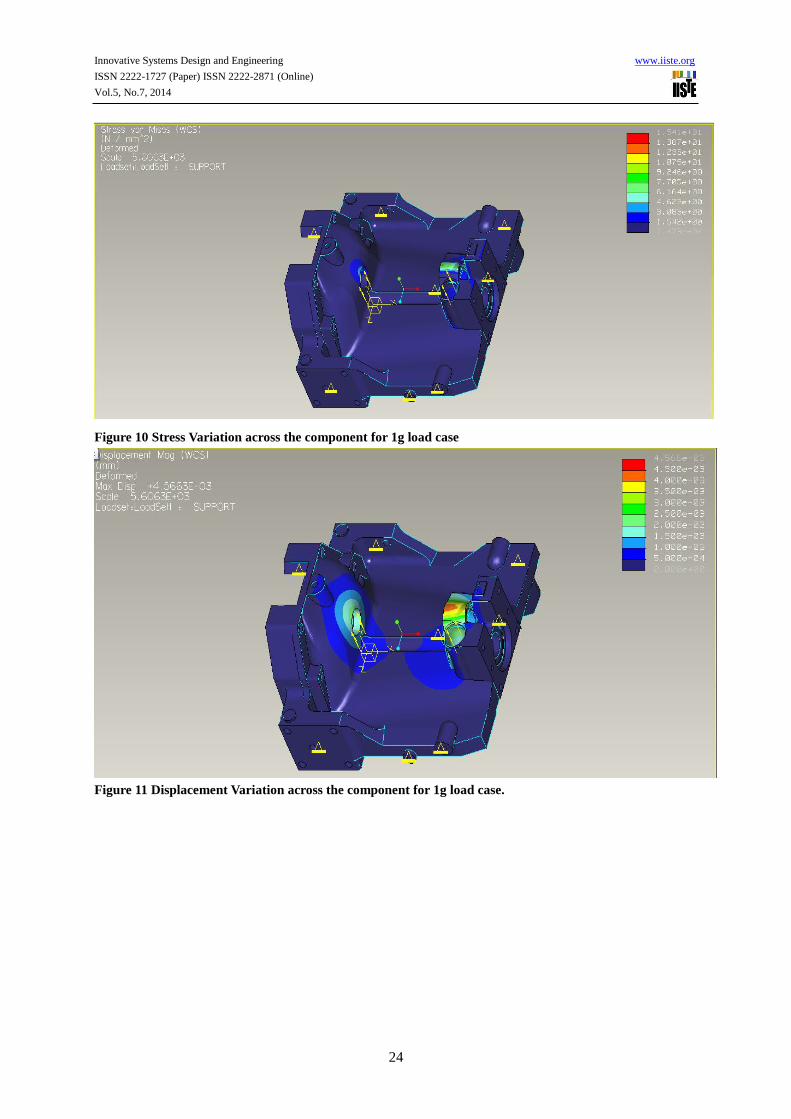
Figure 5 shows the stress variation across the component 1g Load case with maximum value of 15.41N/mm2.
Figure 6 shows the displacement variation across the component for Axle-Rotating- 3g Load case with a
maximum value of 0.00456mm.The convergence of the critical measures (local displacement and Strain energy)
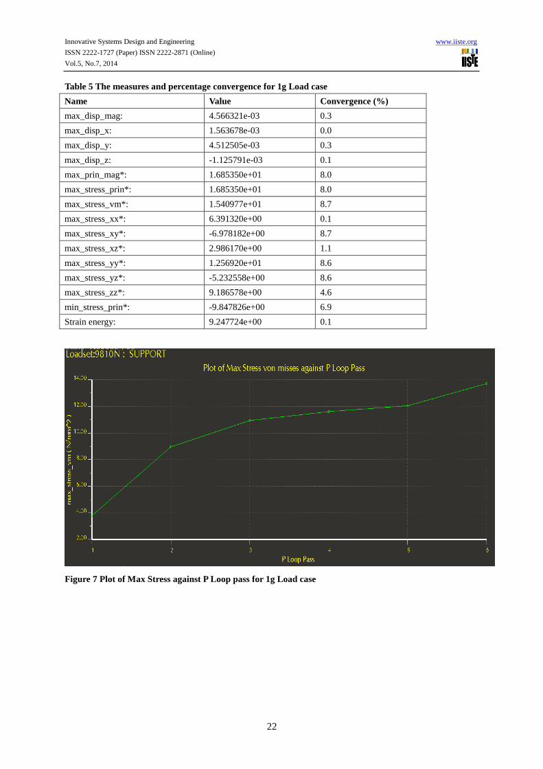
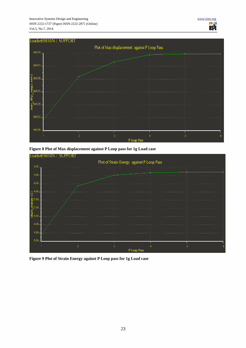
occurs at a polynomial order of 6 which is below the set limit of 9( Figures 7, 8, 9). The convergence of the
measures occurs below the set limit of 10% (Table 4). These ascertain that the results are accurate. The
maximum stress value corresponds to the Analysis results (15N/mm2) of Erukunt Agricultural machinery design
using ANSYS software [9]. The tolerance is ±0.41N/mm2.
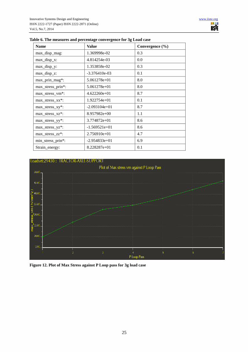
Figure 10 shows the stress variation across the component for 3g Load case with maximum value of
46.22N/mm2. Figure 11 shows the displacement variation across the component for 3g Load case with a
maximum value of 0.0137mm.The convergence of the critical measures (local displacement and Strain energy)
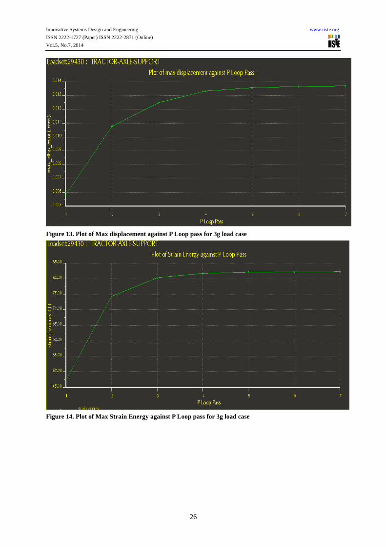
occurs at a polynomial order of 7 which is below the set limit of 9 (Figures 12, 13, 14). The convergence of the
measures occurs below the set limit of 10% (Table 5). These ascertain that the results are accurate. The
maximum stress value corresponds to the Analysis results (45N/mm2) of Erukunt Agricultural machinery design
using ANSYS software [9]. The tolerance is ±1.22N/mm2.
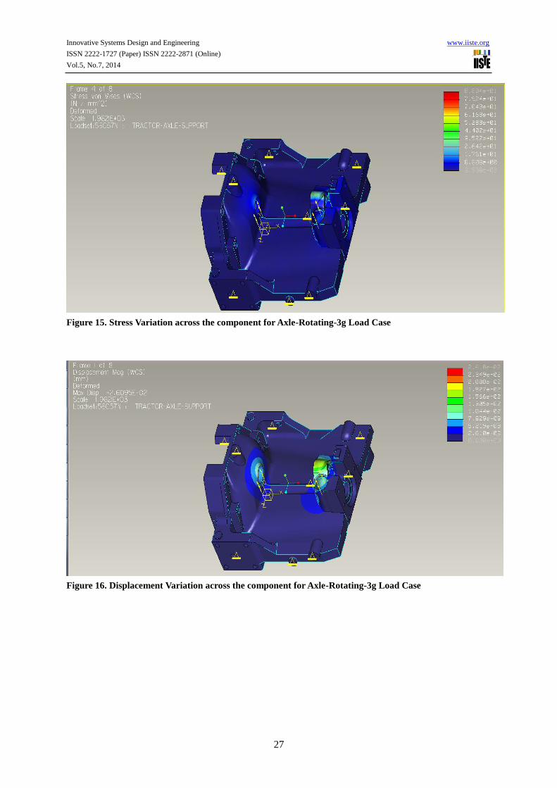
Figure 15 shows the stress variation across the component for Axle-Rotating-3g Load case with maximum value
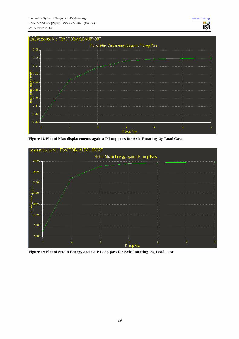
of 88N/mm2. Figure 16 shows the displacement variation across the component for Axle-Rotating-3g Load case
with a maximum value of 0.026mm.The convergence of the critical measures (local displacement and Strain
energy) occurs at a polynomial order of 7 which is below the set limit of 9 (Figures 17, 18,19). The convergence
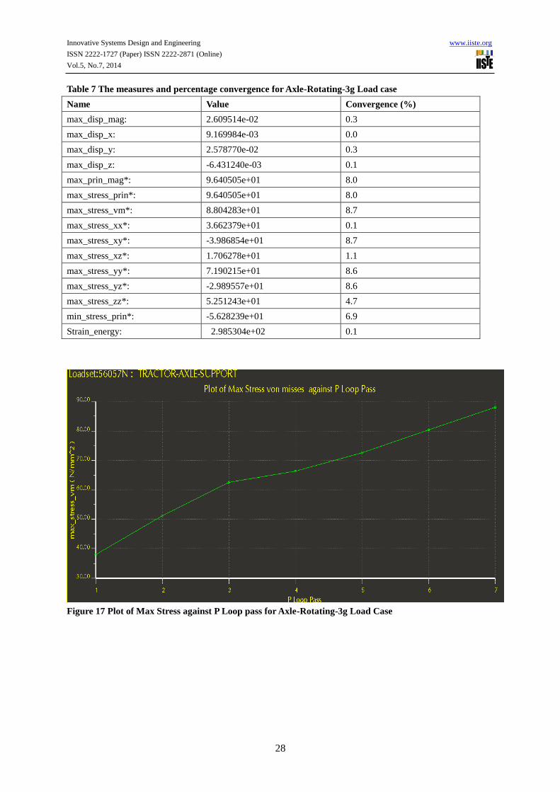
of the measures occurs below the set limit of 10% (Table 6). These ascertain that the results are accurate.

Innovative Systems Design and Engineering www.iiste.org
ISSN 2222-1727 (Paper) ISSN 2222-2871 (Online)
Vol.5, No.7, 2014
21
Figure 5 Stress Variation across the component for 1g load case
Figure 6 Displacement Variation across the component for 1g load case.
Innovative Systems Design and Engineering www.iiste.org
ISSN 2222-1727 (Paper) ISSN 2222-2871 (Online)
Vol.5, No.7, 2014
22
Table 5 The measures and percentage convergence for 1g Load case
Name Value Convergence (%)
max_disp_mag: 4.566321e-03 0.3
max_disp_x: 1.563678e-03 0.0
max_disp_y: 4.512505e-03 0.3
max_disp_z: -1.125791e-03 0.1
max_prin_mag*: 1.685350e+01 8.0
max_stress_prin*: 1.685350e+01 8.0
max_stress_vm*: 1.540977e+01 8.7
max_stress_xx*: 6.391320e+00 0.1
max_stress_xy*: -6.978182e+00 8.7
max_stress_xz*: 2.986170e+00 1.1
max_stress_yy*: 1.256920e+01 8.6
max_stress_yz*: -5.232558e+00 8.6
max_stress_zz*: 9.186578e+00 4.6
min_stress_prin*: -9.847826e+00 6.9
Strain energy: 9.247724e+00 0.1
Figure 7 Plot of Max Stress against P Loop pass for 1g Load case
Innovative Systems Design and Engineering www.iiste.org
ISSN 2222-1727 (Paper) ISSN 2222-2871 (Online)
Vol.5, No.7, 2014
23
Figure 8 Plot of Max displacement against P Loop pass for 1g Load case
Figure 9 Plot of Strain Energy against P Loop pass for 1g Load case
Innovative Systems Design and Engineering www.iiste.org
ISSN 2222-1727 (Paper) ISSN 2222-2871 (Online)
Vol.5, No.7, 2014
24
Figure 10 Stress Variation across the component for 1g load case
Figure 11 Displacement Variation across the component for 1g load case.
Innovative Systems Design and Engineering www.iiste.org
ISSN 2222-1727 (Paper) ISSN 2222-2871 (Online)
Vol.5, No.7, 2014
25
Table 6. The measures and percentage convergence for 3g Load case
Name Value Convergence (%)
max_disp_mag: 1.369998e-02 0.3
max_disp_x: 4.814254e-03 0.0
max_disp_y: 1.353858e-02 0.3
max_disp_z: -3.376410e-03 0.1
max_prin_mag*: 5.061278e+01 8.0
max_stress_prin*: 5.061278e+01 8.0
max_stress_vm*: 4.622260e+01 8.7
max_stress_xx*: 1.922754e+01 0.1
max_stress_xy*: -2.093104e+01 8.7
max_stress_xz*: 8.957982e+00 1.1
max_stress_yy*: 3.774872e+01 8.6
max_stress_yz*: -1.569521e+01 8.6
max_stress_zz*: 2.756910e+01 4.7
min_stress_prin*: -2.954833e+01 6.9
Strain_energy: 8.228287e+01 0.1
Figure 12. Plot of Max Stress against P Loop pass for 3g load case
Innovative Systems Design and Engineering www.iiste.org
ISSN 2222-1727 (Paper) ISSN 2222-2871 (Online)
Vol.5, No.7, 2014
26
Figure 13. Plot of Max displacement against P Loop pass for 3g load case
Figure 14. Plot of Max Strain Energy against P Loop pass for 3g load case
Innovative Systems Design and Engineering www.iiste.org
ISSN 2222-1727 (Paper) ISSN 2222-2871 (Online)
Vol.5, No.7, 2014
27
Figure 15. Stress Variation across the component for Axle-Rotating-3g Load Case
Figure 16. Displacement Variation across the component for Axle-Rotating-3g Load Case
Innovative Systems Design and Engineering www.iiste.org
ISSN 2222-1727 (Paper) ISSN 2222-2871 (Online)
Vol.5, No.7, 2014
28
Table 7 The measures and percentage convergence for Axle-Rotating-3g Load case
Name Value Convergence (%)
max_disp_mag: 2.609514e-02 0.3
max_disp_x: 9.169984e-03 0.0
max_disp_y: 2.578770e-02 0.3
max_disp_z: -6.431240e-03 0.1
max_prin_mag*: 9.640505e+01 8.0
max_stress_prin*: 9.640505e+01 8.0
max_stress_vm*: 8.804283e+01 8.7
max_stress_xx*: 3.662379e+01 0.1
max_stress_xy*: -3.986854e+01 8.7
max_stress_xz*: 1.706278e+01 1.1
max_stress_yy*: 7.190215e+01 8.6
max_stress_yz*: -2.989557e+01 8.6
max_stress_zz*: 5.251243e+01 4.7
min_stress_prin*: -5.628239e+01 6.9
Strain_energy: 2.985304e+02 0.1
Figure 17 Plot of Max Stress against P Loop pass for Axle-Rotating-3g Load Case
Innovative Systems Design and Engineering www.iiste.org
ISSN 2222-1727 (Paper) ISSN 2222-2871 (Online)
Vol.5, No.7, 2014
29
Figure 18 Plot of Max displacements against P Loop pass for Axle-Rotating- 3g Load Case
Figure 19 Plot of Strain Energy against P Loop pass for Axle-Rotating- 3g Load Case
Innovative Systems Design and Engineering www.iiste.org
ISSN 2222-1727 (Paper) ISSN 2222-2871 (Online)
Vol.5, No.7, 2014
30
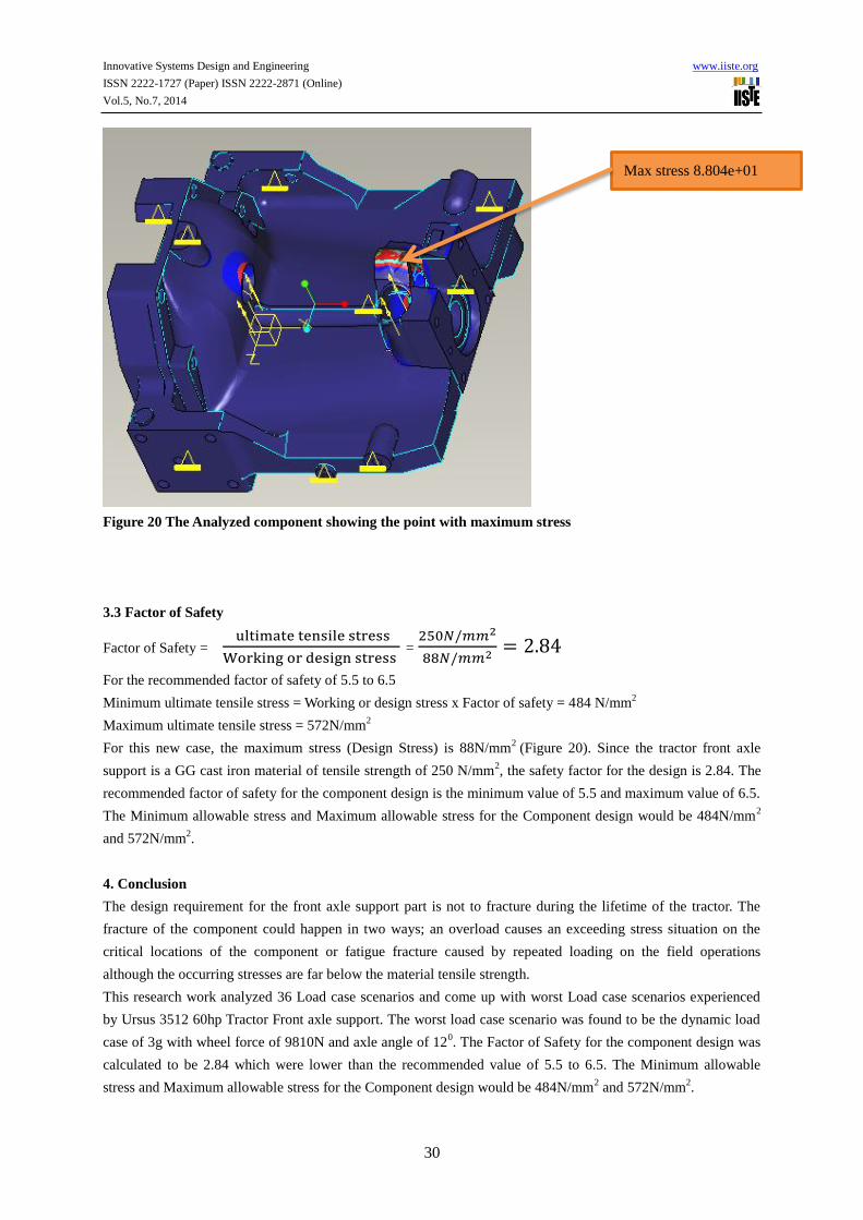
Figure 20 The Analyzed component showing the point with maximum stress
3.3 Factor of Safety
Factor of Safety = ultimate tensile stress
Working or design stress =
250𝑁/𝑚𝑚2
88𝑁/𝑚𝑚2= 2.84
For the recommended factor of safety of 5.5 to 6.5
Minimum ultimate tensile stress = Working or design stress x Factor of safety = 484 N/mm2
Maximum ultimate tensile stress = 572N/mm2
For this new case, the maximum stress (Design Stress) is 88N/mm2
(Figure 20). Since the tractor front axle
support is a GG cast iron material of tensile strength of 250 N/mm2, the safety factor for the design is 2.84. The
recommended factor of safety for the component design is the minimum value of 5.5 and maximum value of 6.5.
The Minimum allowable stress and Maximum allowable stress for the Component design would be 484N/mm2
and 572N/mm2.
4. Conclusion
The design requirement for the front axle support part is not to fracture during the lifetime of the tractor. The
fracture of the component could happen in two ways; an overload causes an exceeding stress situation on the
critical locations of the component or fatigue fracture caused by repeated loading on the field operations
although the occurring stresses are far below the material tensile strength.
This research work analyzed 36 Load case scenarios and come up with worst Load case scenarios experienced
by Ursus 3512 60hp Tractor Front axle support. The worst load case scenario was found to be the dynamic load
case of 3g with wheel force of 9810N and axle angle of 120. The Factor of Safety for the component design was
calculated to be 2.84 which were lower than the recommended value of 5.5 to 6.5. The Minimum allowable
stress and Maximum allowable stress for the Component design would be 484N/mm2 and 572N/mm
2.
Max stress 8.804e+01
Innovative Systems Design and Engineering www.iiste.org
ISSN 2222-1727 (Paper) ISSN 2222-2871 (Online)
Vol.5, No.7, 2014
31
References
1 Spath R., “Sensor wheel for recording wheel forces at the tractor rear axle” Agrartechnische Forschung
July,2001
2 Spath R , “Measurement Load Spectra for the Tractor Chassis”, Institute of Agricultural Machinery, TU
MUNCHEN, 1999
3 Miner, M.A., “Cumulative Damage in Fatigue “, ASME Journal of Applied Mechanics, S.A 159-A164
American Society of Mechanical Engineers (ASME), New York, 1945
4 Azmi Bin Dato Hj, Yahya, “A Tractor data acquisition System of Field Power and Energy Demand
Mapping “, Dept of Biological and Agricultural Engineering Faculty of Engineering University Putra
Malaysia, 1999
5 Al – Janobi A. A.,Al – Suhaibani S. A., “A Data Acquisition System to Monitor Tractor Performance
“A Paper Presented at the1996 ASAE Annual International Meeting, July ,1996
6 Balasubramanian, K., Thomas F. Burks , Cj. Lehtola and W.S. Lee , “Development of an off-Road
Vehicle Data Acquisition Systems for Assessing the influences of Vehicle shock and vibration on
operator Health and Safety”, 2004 National symposium on Agricultural Health and Safety” , Keystone ,
CO. June 21-23, 2004
7 Dinesh Redkar , “Non Linear Analysis of Farm Tractor Front Axle using Abaqus CAE”, Mahindra
tractors, TU MUNCHEN, 2000
8 Dilip K Mahanty, Vikas Manohar, Bhushan S Khomane, Swarnendu Nayak, “Analysis and Weight
Reduction of a Tractor‘s Front Axle”, Tata industries, India, 1995
9 Atayil Koyuncu, “Acquisition of Field Data For Agricultural Tractor” M.Sc Thesis submitted to
mechanical Engineering department, Middle east Technical university, Turkey,May,2006
10 R.S. Khurmi, J.K.Gupta, “A Textbook of Machine Design” Eurasia Publishing House LTD, 14th
Revised Edition, 2009
The IISTE is a pioneer in the Open-Access hosting service and academic event
management. The aim of the firm is Accelerating Global Knowledge Sharing.
More information about the firm can be found on the homepage:
http://www.iiste.org
CALL FOR JOURNAL PAPERS
There are more than 30 peer-reviewed academic journals hosted under the hosting
platform.
Prospective authors of journals can find the submission instruction on the
following page: http://www.iiste.org/journals/ All the journals articles are available
online to the readers all over the world without financial, legal, or technical barriers
other than those inseparable from gaining access to the internet itself. Paper version
of the journals is also available upon request of readers and authors.
MORE RESOURCES
Book publication information: http://www.iiste.org/book/
IISTE Knowledge Sharing Partners
EBSCO, Index Copernicus, Ulrich's Periodicals Directory, JournalTOCS, PKP Open
Archives Harvester, Bielefeld Academic Search Engine, Elektronische
Zeitschriftenbibliothek EZB, Open J-Gate, OCLC WorldCat, Universe Digtial
Library , NewJour, Google Scholar

Business, Economics, Finance and Management Journals PAPER SUBMISSION EMAIL European Journal of Business and Management [email protected]
Research Journal of Finance and Accounting [email protected] Journal of Economics and Sustainable Development [email protected] Information and Knowledge Management [email protected] Journal of Developing Country Studies [email protected] Industrial Engineering Letters [email protected]
Physical Sciences, Mathematics and Chemistry Journals PAPER SUBMISSION EMAIL Journal of Natural Sciences Research [email protected] Journal of Chemistry and Materials Research [email protected] Journal of Mathematical Theory and Modeling [email protected] Advances in Physics Theories and Applications [email protected] Chemical and Process Engineering Research [email protected]
Engineering, Technology and Systems Journals PAPER SUBMISSION EMAIL Computer Engineering and Intelligent Systems [email protected] Innovative Systems Design and Engineering [email protected] Journal of Energy Technologies and Policy [email protected] Information and Knowledge Management [email protected] Journal of Control Theory and Informatics [email protected] Journal of Information Engineering and Applications [email protected] Industrial Engineering Letters [email protected] Journal of Network and Complex Systems [email protected]
Environment, Civil, Materials Sciences Journals PAPER SUBMISSION EMAIL Journal of Environment and Earth Science [email protected] Journal of Civil and Environmental Research [email protected] Journal of Natural Sciences Research [email protected]
Life Science, Food and Medical Sciences PAPER SUBMISSION EMAIL Advances in Life Science and Technology [email protected] Journal of Natural Sciences Research [email protected] Journal of Biology, Agriculture and Healthcare [email protected] Journal of Food Science and Quality Management [email protected] Journal of Chemistry and Materials Research [email protected]
Education, and other Social Sciences PAPER SUBMISSION EMAIL Journal of Education and Practice [email protected] Journal of Law, Policy and Globalization [email protected] Journal of New Media and Mass Communication [email protected] Journal of Energy Technologies and Policy [email protected]
Historical Research Letter [email protected] Public Policy and Administration Research [email protected] International Affairs and Global Strategy [email protected]
Research on Humanities and Social Sciences [email protected] Journal of Developing Country Studies [email protected] Journal of Arts and Design Studies [email protected]
![Tilting Modules and their Applicationsknr/past/vdk/mathieu.pdf · Tilting modules and their applications 147 than the original proof [GM2]. The applications of the tilting module](https://img.pdfslide.us/doc/110x75/5edd392bad6a402d66683d22/tilting-modules-and-their-applications-knrpastvdk-tilting-modules-and-their.jpg)


![A Narrow-Track Tilting Tricycle with Variable Stability ...€¦ · steering geometry. [4] Another solution, the recumbent tricycle, must have a wide axle track for lateral stability](https://img.pdfslide.us/doc/110x75/605e7734d368397e5f1fa8d9/a-narrow-track-tilting-tricycle-with-variable-stability-steering-geometry-4.jpg)