Embed Size (px)
Citation preview
Vol-2 Issue-3 2016 IJARIIE-ISSN(O)-2395-4396
2223 www.ijariie.com 342
Computer Aided Process Design for
Hydrogenation of Oil using Jet Loop Reactor Bhavika J. Parmar1, Prof. S. M. Dutta2, Prof. S. B. Thakore3
1Chemical Engg. Dept., L. D. College of Engineering, Ahmedabad – 380015 2Chemical Engg. Dept., L. D. College of Engineering, Ahmedabad – 380015 3Chemical Engg. Dept., L. D. College of Engineering, Ahmedabad – 380015
Abstract:
The paper presented here is study about jet loop reactor technology for hydrogenation amination alkylation. A Jet
Loop Reactor consists of a reaction autoclave, a circulation pump, a heat exchanger, a venturi type ejector similar
to Stirred Tank Reactor but is arranged in a completely different way. To provide ease to designing, a scilab based
program is developed and tested for two types of oil, soyabean oil as well as palm oil.
Keyword: Evaporative Condenser, Design of Condenser, scilab, Program for Evaporative Condenser
1. INTRODUCTION
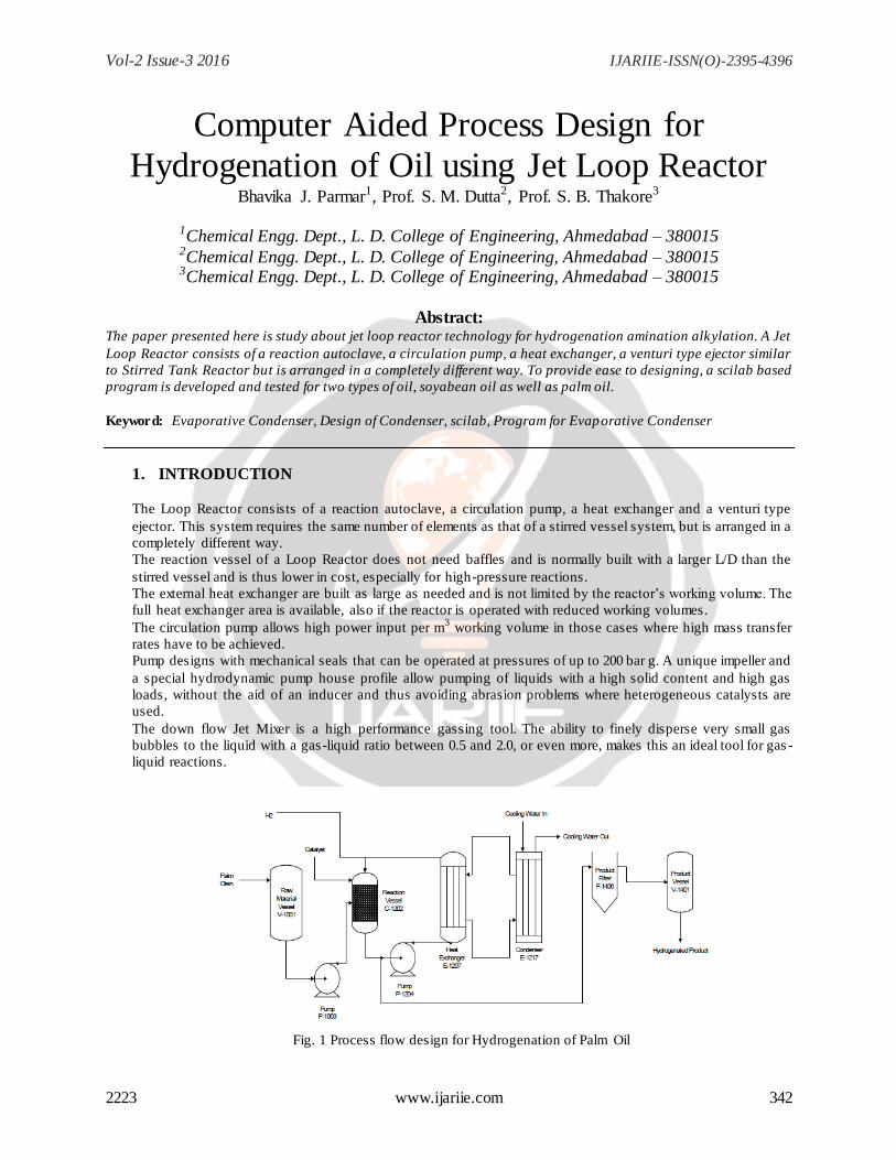
The Loop Reactor consists of a reaction autoclave, a circulation pump, a heat exchanger and a venturi type
ejector. This system requires the same number of elements as that of a stirred vessel system, but is arranged in a
completely different way.
The reaction vessel of a Loop Reactor does not need baffles and is normally built with a larger L/D than the
stirred vessel and is thus lower in cost, especially for high-pressure reactions.
The external heat exchanger are built as large as needed and is not limited by the reactor‟s working volume. The
full heat exchanger area is available, also if the reactor is operated with reduced working volumes.
The circulation pump allows high power input per m3 working volume in those cases where high mass transfer
rates have to be achieved.
Pump designs with mechanical seals that can be operated at pressures of up to 200 bar g. A unique impeller and
a special hydrodynamic pump house profile allow pumping of liquids with a high solid content and high gas
loads, without the aid of an inducer and thus avoiding abrasion problems where heterogeneous catalysts are
used.
The down flow Jet Mixer is a high performance gassing tool. The ability to finely disperse very small gas
bubbles to the liquid with a gas -liquid ratio between 0.5 and 2.0, or even more, makes this an ideal tool for gas -
liquid reactions.
Fig. 1 Process flow design for Hydrogenation of Palm Oil
Vol-2 Issue-3 2016 IJARIIE-ISSN(O)-2395-4396
2223 www.ijariie.com 343
Advantages
Jet Loop Reactor possess several benefits which makes it substantial for various industrial applications, these
benefits include; Firstly, it promotes a faster reaction rate by exerting its higher mass transfer rate & mixing intensity
as compare to continuous stirred tank reactor (CSTR).
Secondly, absence of moving parts in jet loop reactors eliminates the sealing problems and allows easier operation at
elevated pressure. Third, Length to diameter ratio of jet reactor is higher than same of agitated vessel, thus it
requires less cost particularly for high pressure reactions.
Next, the external heat exchanger can be built as needed and can have accurate temperature control even if the
reactor is operated with reduced working volumes.
Moreover, the maximum power input per unit volume is often a limiting factor, especially for large reactors with an
agitator. Since there is no agitator in the jet reactor, this limitation does not exist.
Lastly, the circulation pump can provide very high power per m3 of working volumes if it is required to achieve the
desired mass transfer rate
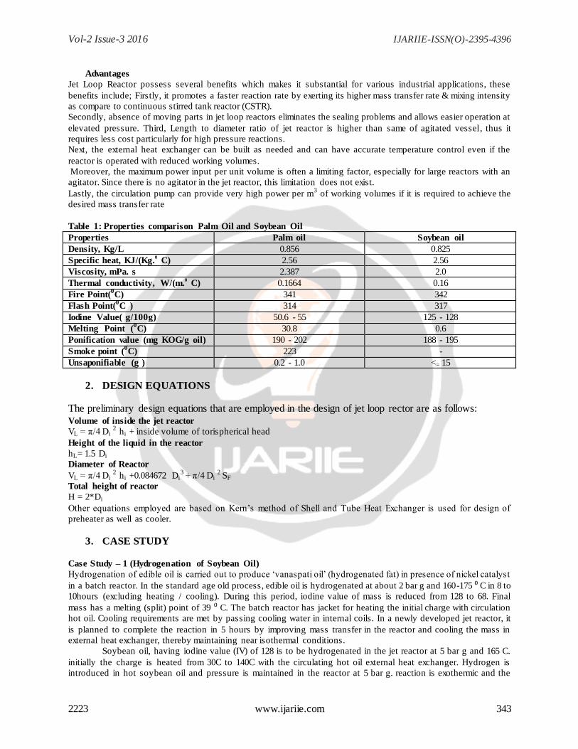
Table 1: Properties comparison Palm Oil and Soybean Oil
Properties Palm oil Soybean oil
Density, Kg/L 0.856 0.825
Specific heat, KJ/(Kg.⁰ C) 2.56 2.56
Viscosity, mPa. s 2.387 2.0
Thermal conductivity, W/(m.⁰ C) 0.1664 0.16
Fire Point(0C) 341 342
Flash Point(0C ) 314 317
Iodine Value( g/100g) 50.6 - 55 125 - 128
Melting Point (0C) 30.8 0.6
Ponification value (mg KOG/g oil) 190 - 202 188 - 195
Smoke point (0C) 223 -
Unsaponifiable (g ) 0.2 - 1.0 <= 15
2. DESIGN EQUATIONS The preliminary design equations that are employed in the design of jet loop rector are as follows: Volume of inside the jet reactor
VL = π/4 Di 2
hi + inside volume of torispherical head
Height of the liquid in the reactor
hL= 1.5 Di
Diameter of Reactor
VL = π/4 Di 2
hi +0.084672 Di3 + π/4 Di
2 SF
Total height of reactor
H = 2*Di
Other equations employed are based on Kern‟s method of Shell and Tube Heat Exchanger is used for design of
preheater as well as cooler.
3. CASE STUDY
Case Study – 1 (Hydrogenation of Soybean Oil)
Hydrogenation of edible oil is carried out to produce „vanaspati oil‟ (hydrogenated fat) in presence of nickel catalyst
in a batch reactor. In the standard age old process, edible oil is hydrogenated at about 2 bar g and 160-175 ⁰ C in 8 to
10hours (excluding heating / cooling). During this period, iodine value of mass is reduced from 128 to 68. Final
mass has a melting (split) point of 39 ⁰ C. The batch reactor has jacket for heating the initial charge with circulation
hot oil. Cooling requirements are met by passing cooling water in internal coils. In a newly developed jet reactor, it
is planned to complete the reaction in 5 hours by improving mass transfer in the reactor and cooling the mass in
external heat exchanger, thereby maintaining near isothermal conditions.
Soybean oil, having iodine value (IV) of 128 is to be hydrogenated in the jet reactor at 5 bar g and 165 C.
initially the charge is heated from 30C to 140C with the circulating hot oil external heat exchanger. Hydrogen is
introduced in hot soybean oil and pressure is maintained in the reactor at 5 bar g. reaction is exothermic and the
Vol-2 Issue-3 2016 IJARIIE-ISSN(O)-2395-4396
2223 www.ijariie.com 344
temperature of mass increases. Cold oil flow in the external heat exchanger controls the temperature at 165 C as per
the requirement; IV reduction is desired up to 68 when the reaction is considered over. Thereafter hydrogenated
mass is cooled to 60C IN about 1.5h before it is discharged to filter. 150 kg spent nickel catalyst is charged with
soybean oil while fresh 5 to 10 kg nickel catalyst is charged at intervals in the reactor under pressure. A bleed is
maintained from the system to purge out water vapor and non-condensables. Design the jet reactor for the following
duty.
1] Charge = 10t soybean oil with 128 IV
2] Average molar mass of soybean oil = 278
3] Average chain length of fatty acids = 17.78
4] Product specifications: 68IV, 39 0C melting point (max.). Assume linear drop of IV in 5 hours.
5] Average exothermic heat of reaction = 7.1 kJ/kg of IV reduction
6] Hydrogen feed rate = 110 to 125 Nm3/h
Bleed rate = 1 to 2 Nm3/h
7] Thermic fluid or oil is used as both, heating medium in starting of reaction and cooling medium in running of
reaction.
8] Cooling water is available at 2 bar g and 32C .a rise of 5C is permitted. Cooling water is used for cooling water is
used for cooling the oil from 80C to 70C in oil cooler (HE-2) of oil cycle.
9] Assume following properties of fluids for the design.
Average properties of edible oil and circulating oil
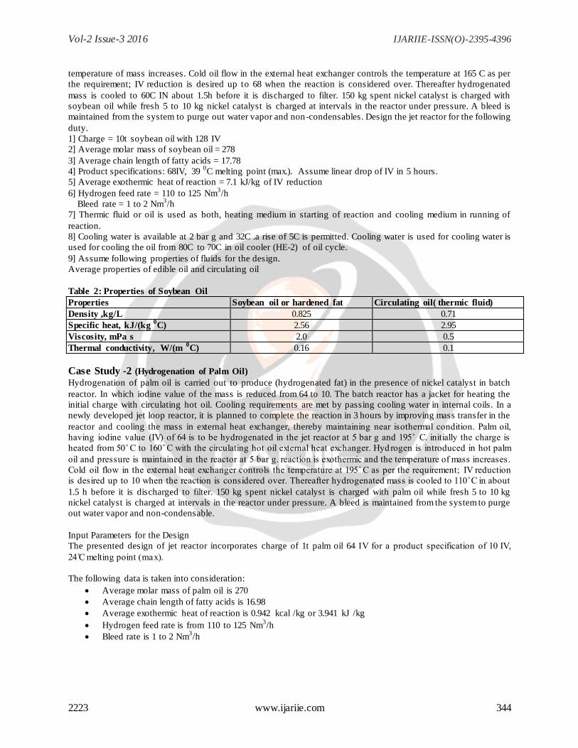
Table 2: Properties of Soybean Oil
Properties Soybean oil or hardened fat Circulating oil( thermic fluid)
Density ,kg/L 0.825 0.71
Specific heat, kJ/(kg 0C) 2.56 2.95
Viscosity, mPa s 2.0 0.5
Thermal conductivity, W/(m 0C) 0.16 0.1
Case Study -2 (Hydrogenation of Palm Oil) Hydrogenation of palm oil is carried out to produce (hydrogenated fat) in the presence of nickel catalyst in batch
reactor. In which iodine value of the mass is reduced from 64 to 10. The batch reactor has a jacket for heating the
initial charge with circulating hot oil. Cooling requirements are met by passing cooling water in internal coils. In a
newly developed jet loop reactor, it is planned to complete the reaction in 3 hours by improving mass transfer in the
reactor and cooling the mass in external heat exchanger, thereby maintaining near isothermal condition. Palm oil
having iodine value ( V) of 64 is to be hydrogenated in the jet reactor at 5 bar g and 195 . initially the charge is
heated from 50 to 160 with the circulating hot oil external heat exchanger. Hydrogen is introduced in hot palm
oil and pressure is maintained in the reactor at 5 bar g. reaction is exothermic and the temperature of mass increases.
old oil flow in the external heat exchanger controls the temperature at 195 as per the requirement V reduction
is desired up to 10 when the reaction is considered over. Thereafter hydrogenated mass is cooled to 110 in about
1.5 h before it is discharged to filter. 150 kg spent nickel catalyst is charged with palm oil while fresh 5 to 10 kg
nickel catalyst is charged at intervals in the reactor under pressure. A bleed is maintained from the system to purge
out water vapor and non-condensable.
Input Parameters for the Design
The presented design of jet reactor incorporates charge of 1t palm oil 64 IV for a product specification of 10 V
24 melting point (max).
The following data is taken into consideration:
Average molar mass of palm oil is 270
Average chain length of fatty acids is 16.98
Average exothermic heat of reaction is 0.942 kcal /kg or 3.941 kJ /kg
Hydrogen feed rate is from 110 to 125 Nm3/h
Bleed rate is 1 to 2 Nm3/h
Vol-2 Issue-3 2016 IJARIIE-ISSN(O)-2395-4396
2223 www.ijariie.com 345
Thermic fluid or oil is used as both heating medium in starting of reaction and cooling medium in running of
reaction. ooling water is available at 2 bar g and 32 . rise of 5 is permitted over here. ooling water is used
for cooling the oil from 80 to 70 in o il cooler (HE-2) of oil cycle.
The following average properties of fluids for the design are taken:
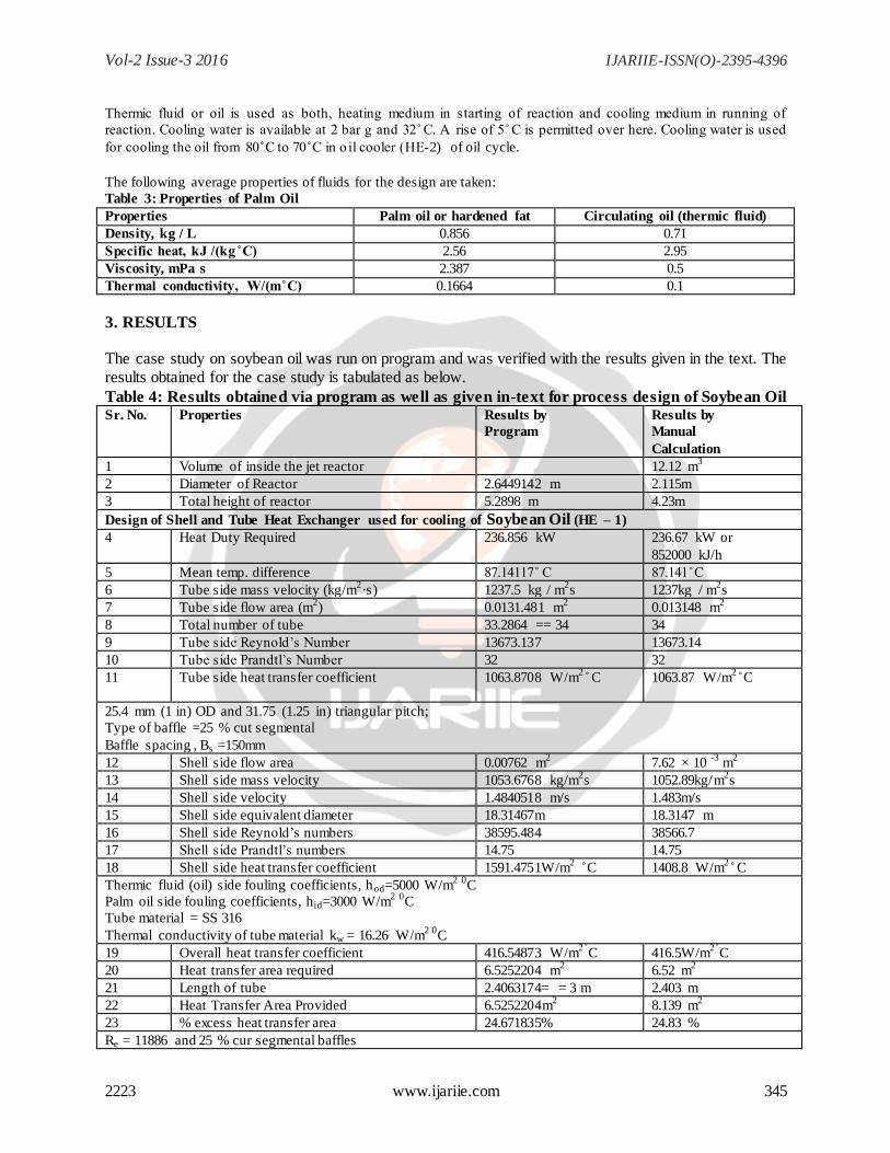
Table 3: Properties of Palm Oil
Properties Palm oil or hardened fat Circulating oil (thermic fluid)
Density, kg / L 0.856 0.71
2.56 2.95
Viscosity, mPa s 2.387 0.5
0.1664 0.1
3. RESULTS
The case study on soybean oil was run on program and was verified with the results given in the text. The results obtained for the case study is tabulated as below.
Table 4: Results obtained via program as well as given in-text for process design of Soybean Oil Sr. No. Properties Results by
Program
Results by
Manual
Calculation
1 Volume of inside the jet reactor 12.12 m3
2 Diameter of Reactor 2.6449142 m 2.115m
3 Total height of reactor 5.2898 m 4.23m
Design of Shell and Tube Heat Exchanger used for cooling of Soybean Oil (HE – 1)
4 Heat Duty Required 236.856 kW 236.67 kW or
852000 kJ/h
5 Mean temp. difference 87.14117 87.141
6 Tube side mass velocity (kg/m2·s) 1237.5 kg / m
2s 1237kg / m
2s
7 Tube side flow area (m2) 0.0131.481 m
2 0.013148 m
2
8 Total number of tube 33.2864 == 34 34
9 Tube side Reynold‟s Number 13673.137 13673.14
10 Tube side Prandtl‟s Number 32 32
11
Tube side heat transfer coefficient 1063.8708 W/m2 C 1063.87 W/m
2 C
25.4 mm (1 in) OD and 31.75 (1.25 in) triangular pitch;
Type of baffle =25 % cut segmental
Baffle spacing , Bs =150mm
12 Shell side flow area 0.00762 m2 7.62 × 10
-3 m
2
13 Shell side mass velocity 1053.6768 kg/m2s 1052.89kg/m
2s
14 Shell side velocity 1.4840518 m/s 1.483m/s
15 Shell side equivalent diameter 18.31467m 18.3147 m
16 Shell side Reynold‟s numbers 38595.484 38566.7
17 Shell side Prandtl‟s numbers 14.75 14.75
18 Shell side heat transfer coefficient 1591.4751W/m2 C 1408.8 W/m
2 C
Thermic fluid (oil) side fouling coefficients, hod=5000 W/m2 0C
Palm oil side fouling coefficients, hid=3000 W/m2 0C
Tube material = SS 316
Thermal conductivity of tube material kw = 16.26 W/m2 0
C
19 Overall heat transfer coefficient 416.54873 W/m2
C 416.5W/m2
C
20 Heat transfer area required 6.5252204 m2 6.52 m
2
21 Length of tube 2.4063174= = 3 m 2.403 m
22 Heat Transfer Area Provided 6.5252204m2 8.139 m
2
23 % excess heat transfer area 24.671835% 24.83 %
Re = 11886 and 25 % cur segmental baffles
Vol-2 Issue-3 2016 IJARIIE-ISSN(O)-2395-4396
2223 www.ijariie.com 346
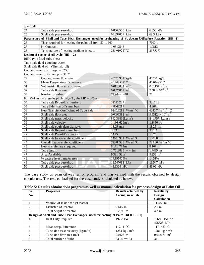
Jf = 0.047
24 Tube side pressure drop 6.8563565 kPa 6.856 kPa
25 Shell side pressure drop 69.397057 kPa 69.3 kPa
Parameters of Shell and Tube Heat Exchanger used for preheating of Soybean Oil before Reaction (HE -1)
26 Time required for heating the palm oil from 50 to 160 7600 s
27 K2 Constant 1.0812546 1.0813
28 Temperature of heating medium inlet, t1 235.919227 217.83
Design of cooler of oil cycle (HE – 2)
BEM type fixed tube sheet
Tube side fluid : cooling water
Shell side fluid oil : (Thermic oil)
ooling water inlet temp. = 32
ooling water outlet temp. = 37
29 Cooling water flow rate 40731.9012kg/h 40700 kg/h
30 Mean Temperature Difference 40.448507 40.04485
31 Volumetric flow rate of water 0.0113804 m3/h 0.01137
m
3/h
32 Tube side flow area 0.0075869 m2 7.58 × 10
-3 m
2
33 Number of tubes 77.942= =78 78
For 25.4 mm triangular pitch , Np= 2 , shell ID = 305mm
34 Tube side Reynold‟s numbers 32171.287 32171.3
35 Tube Side Prandtl‟s numbers 4.8668217 4.867
36 Heat Transfer Coefficient of Tube Side 6240.6211 W/m2 C 6240.7 W/m
2 C
37 Shell side flow area 0.0095312 m2 9.5312 × 10
-3 m
2
38 Shell side mass velocity 842.38866kg/m2s 841.757 kg/m
2s
39 Shell side velocity 1.1864629m/s 1.1856m/s
40 Shell side equivalent diameter 18.25 mm 18.25 mm
41 Shell side Reynolds numbers 30742 30742
42 Shell side Prandtl‟s number 14.75 14.75
43 Shell side heat transfer coefficient 1409.4981 W/ m2 C 1408.8
44 Overall heat transfer coefficient 723.84589 W/ m2 C 723.66 W/ m
2 C
45 Heat transfer area required 8.1714774m2 8.167 m
2
46 Tube length 1.7513839 = = 2m 1.7495 m
47 Area Available 9.331452m2 9.336 m
2
48 % excess heat transfer area 14.195409% 14.31%
49 Tube side pressure drop 13.547012 kPa 13.547 kPa
50 Shell side pressure drop 43.83644kPa 43.06 kPa
The case study on palm oil was run on program and was verified with the results obtained by design calculations. The results obtained for the case study is tabulated as below.
Table 5: Results obtained via program as well as manual calculation for process design of Palm Oil Sr.
No.
Properties Results obtained by
Coding in scilab
Results by
Design
Calculation
1 Volume of inside the jet reactor 11.682 m3
2 Diameter of Reactor 2.645 m 2.1 m
3 Total height of reactor 5.2898 m 4.2 m
Design of Shell and Tube Heat Exchanger used for cooling of Palm Oil (HE – 1)
4 Heat Duty Required 197.2 kW 196.99 kW or
425628 kJ/h
5 Mean temp. difference 117.14 117.1459
6 Tube side mass velocity (kg/m2·s) 1284 kg / m
2s 1284 kg / m
2s
7 Tube side flow area (m2) 0.0127 m
2 0.012671 m
2
8 Total number of tube 33.04 == 34 34
Vol-2 Issue-3 2016 IJARIIE-ISSN(O)-2395-4396
2223 www.ijariie.com 347
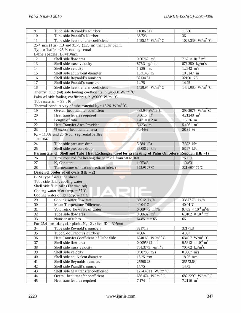
9 Tube side Reynold‟s Number 11886.817 11886
10 Tube side Prandtl‟s Number 36.723 36
11 Tube side heat transfer coefficient 1035.17 W/m2 C 1028.339 W/m
2 C
25.4 mm (1 in) OD and 31.75 (1.25 in) triangular pitch;
Type of baffle =25 % cut segmental
Baffle spacing , Bs =150mm
12 Shell side flow area 0.00762 m2 7.62 × 10
-3 m
2
13 Shell side mass velocity 877.3 kg/m2s 876.350 kg/m
2s
14 Shell side velocity 1.236 m/s 1.2342 m/s
15 Shell side equivalent diameter 18.3146 m 18.3147 m
16 Shell side Reynold‟s numbers 32134.81 32100.175
17 Shell side Prandtl‟s numbers 14.75 14.75
18 Shell side heat transfer coefficient 1438.94 W/m2 C 1438.080 W/m
2 C
Thermic fluid (oil) side fouling coefficients, hod=5000 W/m2 0C
Palm oil side fouling coefficients, h id=3000 W/m2 0C
Tube material = SS 316
Thermal conductivity of tube material kw = 16.26 W/m2 0
C
19 Overall heat transfer coefficient 435.94 W/m2
C 399.2075 W/m2
C
20 Heat transfer area required 3.8615 m2 4.21248 m
2
21 Length of tube 1.42 = = 2 m 1.5526 m
22 Heat Transfer Area Provided 5.4234 m2 5.4261 m
2
23 % excess heat transfer area 40.44% 28.81 %
Re = 11886 and 25 % cur segmental baffles
Jf = 0.047
24 Tube side pressure drop 5.684 kPa 7.323 kPa
25 Shell side pressure drop 36.0812 kPa 53.97 kPa
Parameters of Shell and Tube Heat Exchanger used for preheating of Palm Oil before Reaction (HE -1)
26 Time required for heating the palm oil from 50 to 160 7600 s
27 K2 Constant 1.05346 1.0463
28 Temperature of heating medium inlet, t1 322.9197 321.605477
Design of cooler of oil cycle (HE – 2)
BEM type fixed tube sheet
Tube side fluid : cooling water
Shell side fluid oil : (Thermic oil)
ooling water inlet temp. = 32
ooling water outlet temp. = 37
29 Cooling water flow rate 33912 kg/h 33877.73 kg/h
30 Mean Temperature Difference 40.04 40.04
31 Volumetric flow rate of water 0.009475 m3/h 9.465 × 10
-3 m
3/h
32 Tube side flow area 0.00632 m2 6.3102 × 10
-3 m
2
33 Number of tubes 64.85 = = 65 66
For 25.4 mm triangular pitch , Np= 2 , shell ID = 305mm
34 Tube side Reynold‟s numbers 32171.3 32171.3
35 Tube Side Prandtl‟s numbers 4.866 4.867
36 Heat Transfer Coefficient of Tube Side 6240.62 W/m2 C 6340.7 W/m
2 C
37 Shell side flow area 0.0095312 m2 9.5312 × 10
-3 m
2
38 Shell side mass velocity 701.3775 kg/m2s 700.62 kg/m
2s
39 Shell side velocity 0.98786 m/s 0.9867 m/s
40 Shell side equivalent diameter 18.25 mm 18.25 mm
41 Shell side Reynolds numbers 25596.28 25572.63
42 Shell side Prandtl‟s number 14.75 14.75
43 Shell side heat transfer coefficient 1274.4011 W/ m2 C
44 Overall heat transfer coefficient 686.474 W/ m2 C 682.2290 W/ m
2 C
45 Heat transfer area required 7.174 m2 7.2110 m
2
Vol-2 Issue-3 2016 IJARIIE-ISSN(O)-2395-4396
2223 www.ijariie.com 348
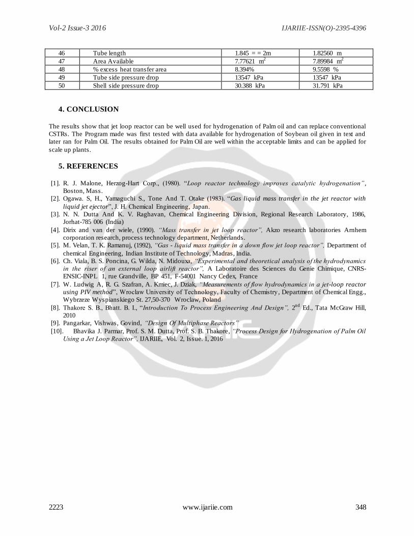
46 Tube length 1.845 = = 2m 1.82560 m
47 Area Available 7.77621 m2 7.89984 m
2
48 % excess heat transfer area 8.394% 9.5598 %
49 Tube side pressure drop 13547 kPa 13547 kPa
50 Shell side pressure drop 30.388 kPa 31.791 kPa
4. CONCLUSION
The results show that jet loop reactor can be well used for hydrogenation of Palm oil and can replace conventional
CSTRs. The Program made was first tested with data available for hydrogenation of Soybean oil given in text and
later ran for Palm Oil. The results obtained for Palm Oil are well within the acceptable limits and can be applied for
scale up plants.
5. REFERENCES
[1]. R. J. Malone, Herzog-Hart orp. (1980). “Loop reactor technology improves catalytic hydrogenation”,
Boston, Mass.
[2]. Ogawa. S, H., Yamaguchi S., Tone And T. Otake (1983). “Gas liquid mass transfer in the jet reactor with
liquid jet ejector” J. H. hemical Engineering Japan.
[3]. N. N. Dutta And K. V. Raghavan, Chemical Engineering Division, Regional Research Laboratory, 1986,
Jorhat-785 006 (India)
[4]. Dirix and van der wiele, (1990). “Mass transfer in jet loop reactor”, Akzo research laboratories Arnhem
corporation research, process technology department, Netherlands.
[5]. M. Velan, T. K. Ramanuj, (1992), “Gas - liquid mass transfer in a down flow jet loop reactor”, Department of
chemical Engineering, Indian Institute of Technology, Madras, India.
[6]. Ch. Viala, B. S. Poncina, G. Wilda, N. Midouxa, “Experimental and theoretical analysis of the hydrodynamics
in the riser of an external loop airlift reactor”, A Laboratoire des Sciences du Genie Chimique, CNRS-
ENSIC-INPL 1, rue Grandville, BP 451, F-54001 Nancy Cedex, France
[7]. W. Ludwig A, R. G. Szafran, A. Kmiec, J. Dziak, “Measurements of flow hydrodynamics in a jet-loop reactor
using PIV method” Wroclaw University of Technology Faculty of hemistry , Department of Chemical Engg.,
Wybrzeze Wyspianskiego St. 27,50-370 Wroclaw, Poland
[8]. Thakore S. B. Bhatt. B. . “Introduction To Process Engineering And Design”, 2nd
Ed., Tata McGraw Hill,
2010
[9]. Pangarkar, Vishwas, Govind, “Design Of Multiphase Reactors”
[10]. Bhavika J. Parmar, Prof. S. M. Dutta, Prof. S. B. Thakore, “Process Design for Hydrogenation of Palm Oil
Using a Jet Loop Reactor”, IJARIIE, Vol. 2, Issue. 1, 2016
Vol-2 Issue-3 2016 IJARIIE-ISSN(O)-2395-4396
2223 www.ijariie.com 349
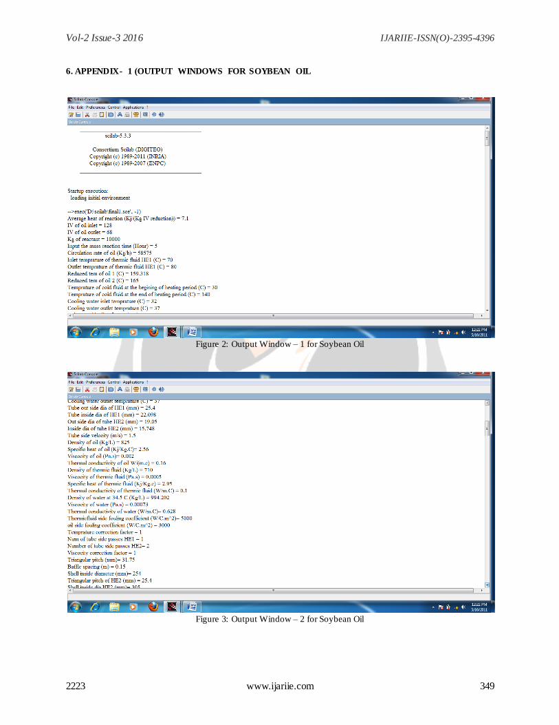
6. APPENDIX- 1 (OUTPUT WINDOWS FOR SOYBEAN OIL
Figure 2: Output Window – 1 for Soybean Oil
Figure 3: Output Window – 2 for Soybean Oil
Vol-2 Issue-3 2016 IJARIIE-ISSN(O)-2395-4396
2223 www.ijariie.com 350
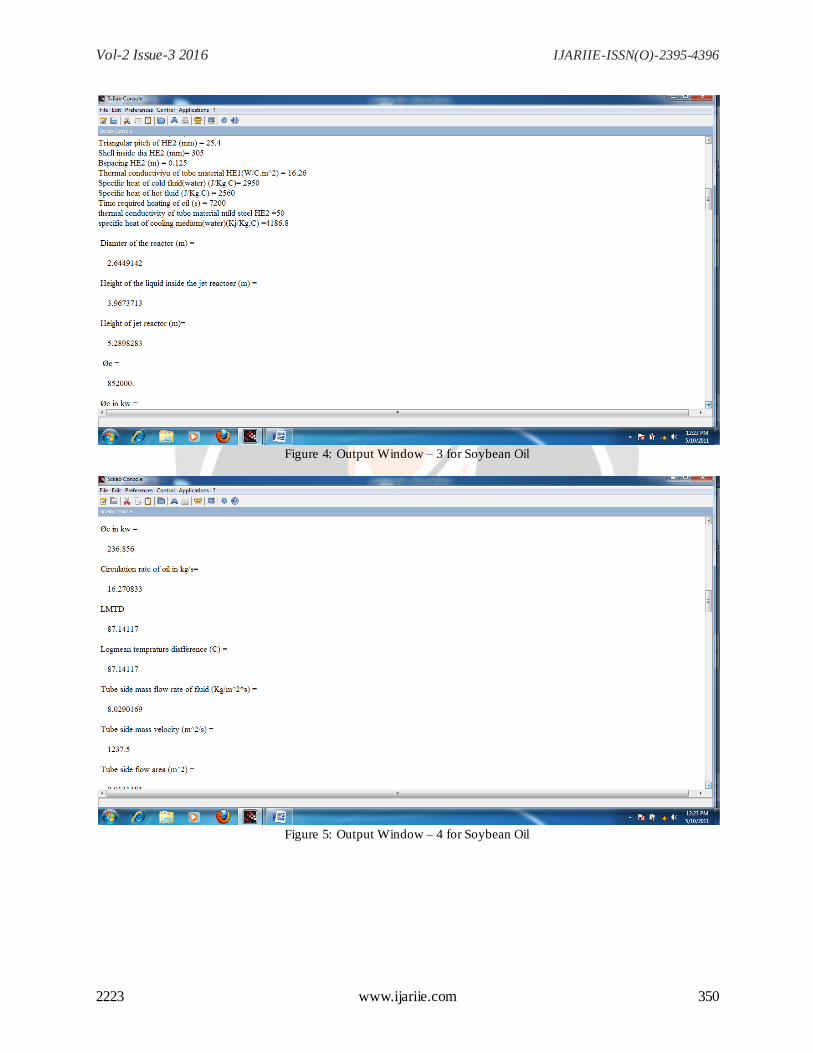
Figure 4: Output Window – 3 for Soybean Oil
Figure 5: Output Window – 4 for Soybean Oil
Vol-2 Issue-3 2016 IJARIIE-ISSN(O)-2395-4396
2223 www.ijariie.com 351
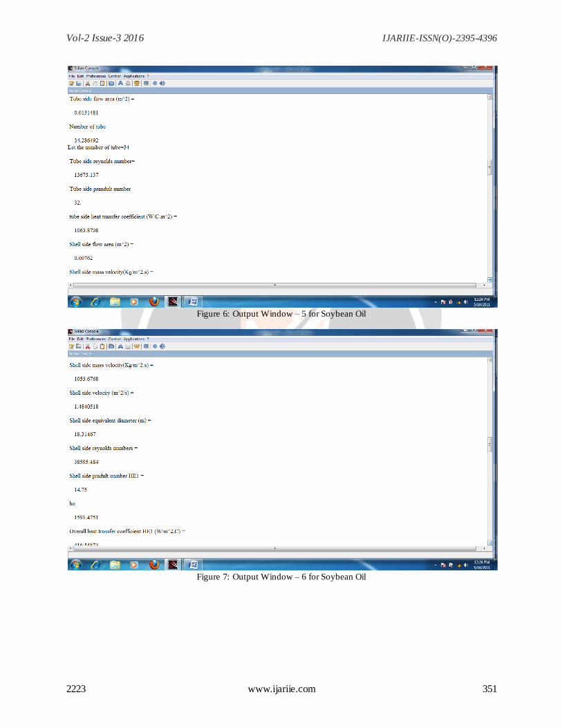
Figure 6: Output Window – 5 for Soybean Oil
Figure 7: Output Window – 6 for Soybean Oil
Vol-2 Issue-3 2016 IJARIIE-ISSN(O)-2395-4396
2223 www.ijariie.com 352
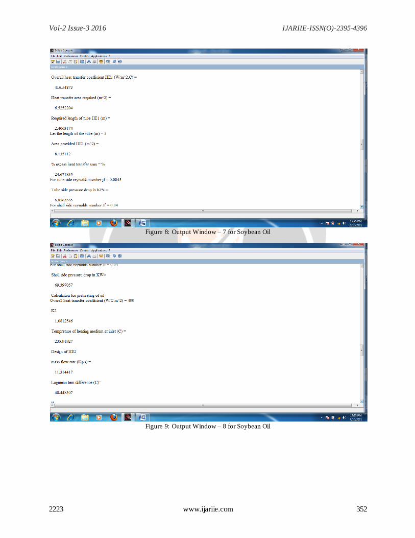
Figure 8: Output Window – 7 for Soybean Oil
Figure 9: Output Window – 8 for Soybean Oil
Vol-2 Issue-3 2016 IJARIIE-ISSN(O)-2395-4396
2223 www.ijariie.com 353
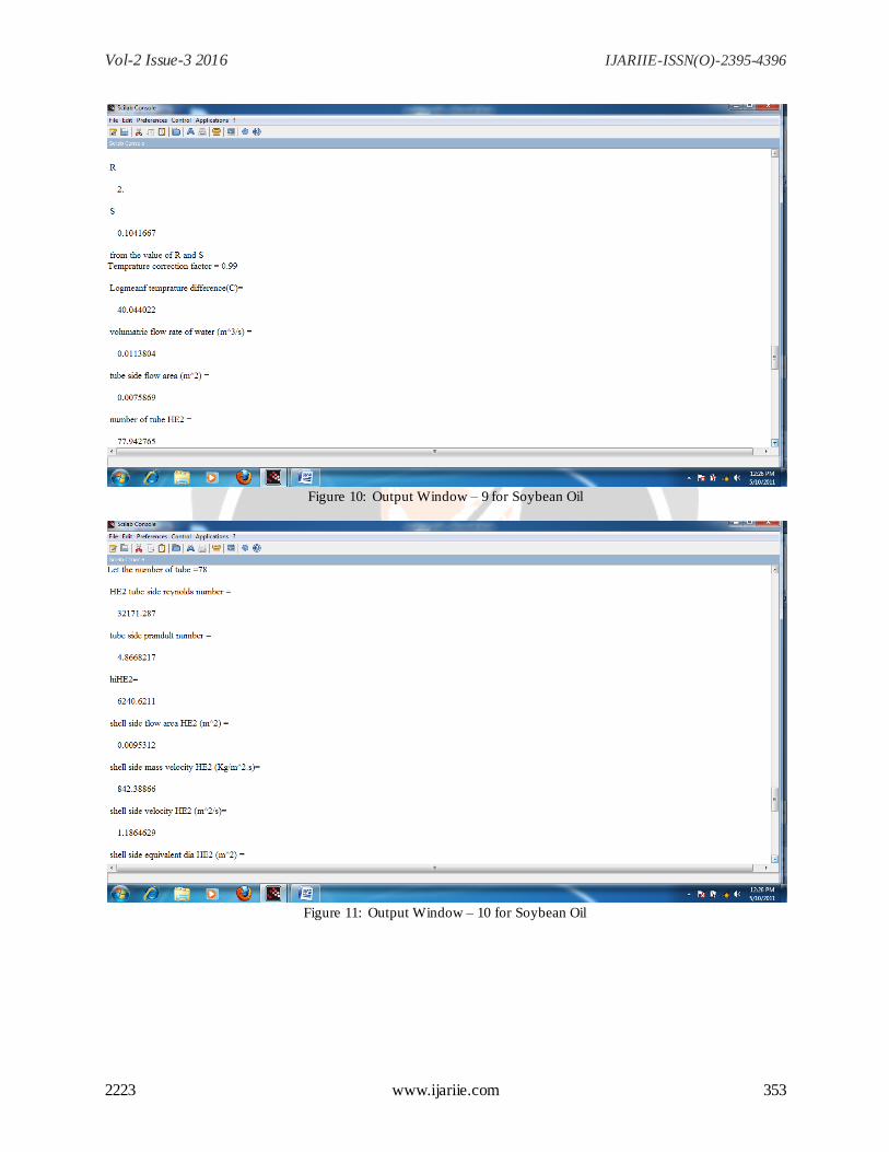
Figure 10: Output Window – 9 for Soybean Oil
Figure 11: Output Window – 10 for Soybean Oil
Vol-2 Issue-3 2016 IJARIIE-ISSN(O)-2395-4396
2223 www.ijariie.com 354
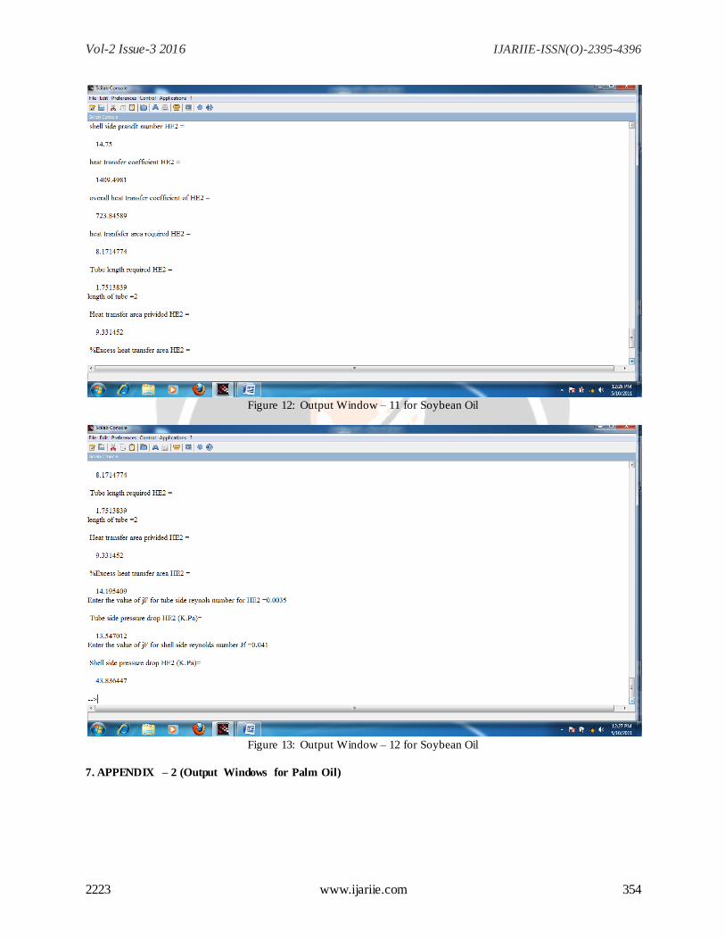
Figure 12: Output Window – 11 for Soybean Oil
Figure 13: Output Window – 12 for Soybean Oil
7. APPENDIX – 2 (Output Windows for Palm Oil)
Vol-2 Issue-3 2016 IJARIIE-ISSN(O)-2395-4396
2223 www.ijariie.com 355
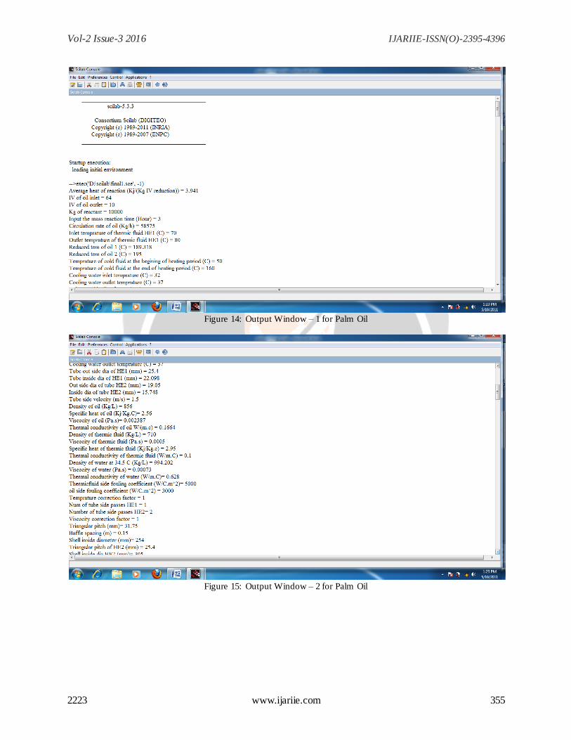
Figure 14: Output Window – 1 for Palm Oil
Figure 15: Output Window – 2 for Palm Oil
Vol-2 Issue-3 2016 IJARIIE-ISSN(O)-2395-4396
2223 www.ijariie.com 356
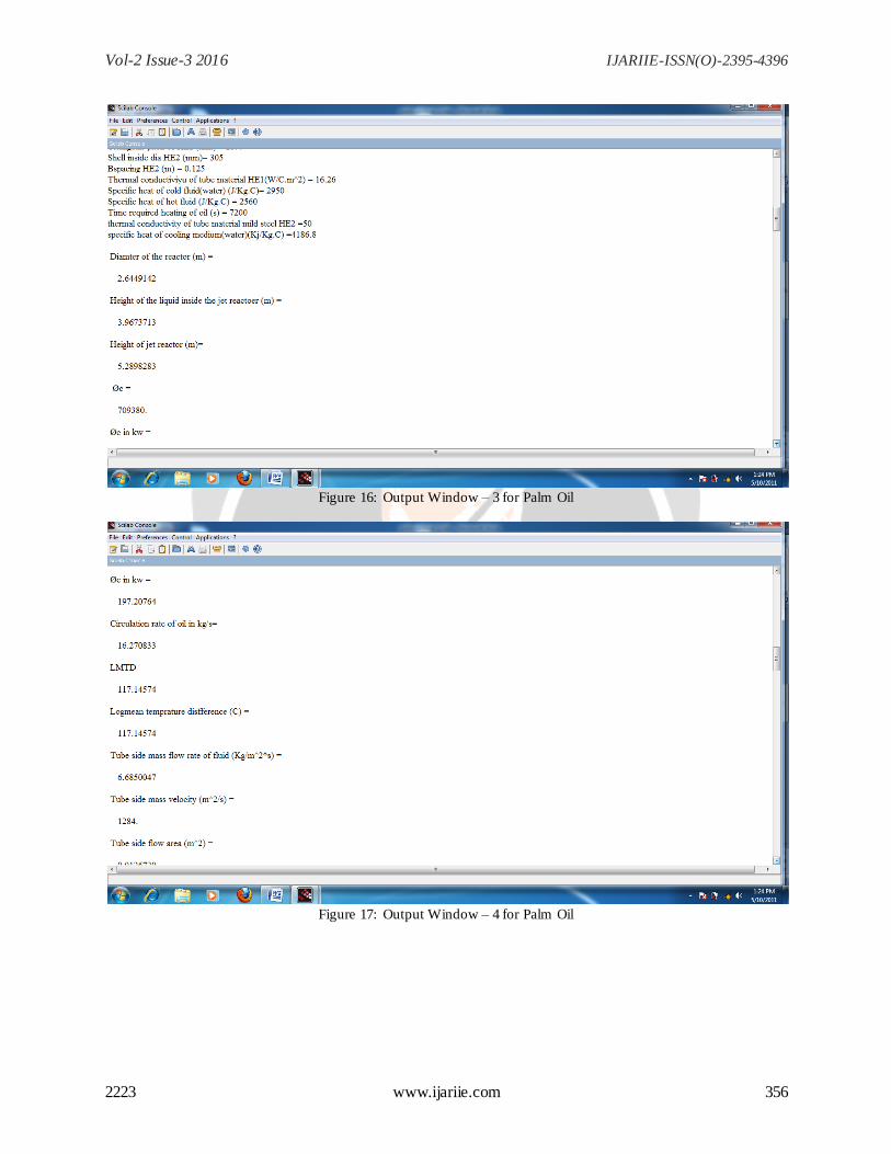
Figure 16: Output Window – 3 for Palm Oil
Figure 17: Output Window – 4 for Palm Oil
Vol-2 Issue-3 2016 IJARIIE-ISSN(O)-2395-4396
2223 www.ijariie.com 357
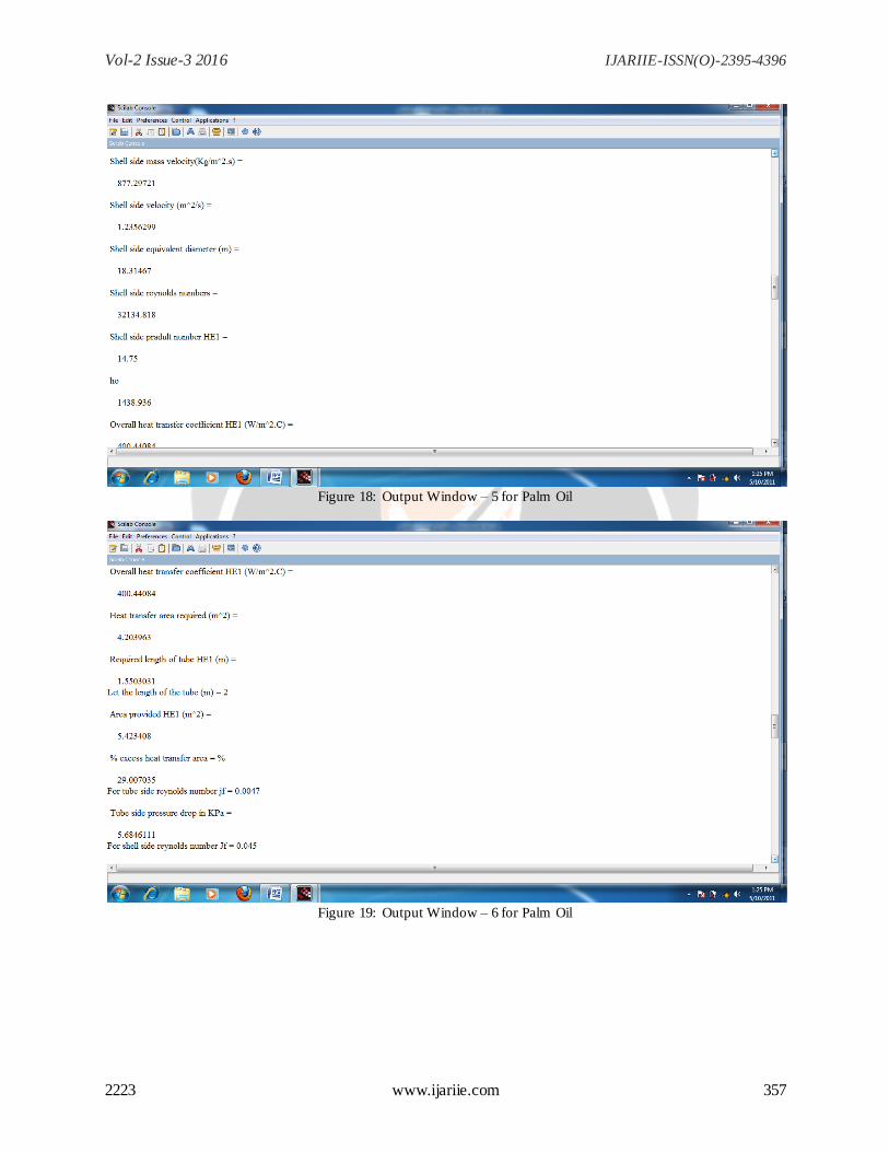
Figure 18: Output Window – 5 for Palm Oil
Figure 19: Output Window – 6 for Palm Oil
Vol-2 Issue-3 2016 IJARIIE-ISSN(O)-2395-4396
2223 www.ijariie.com 358
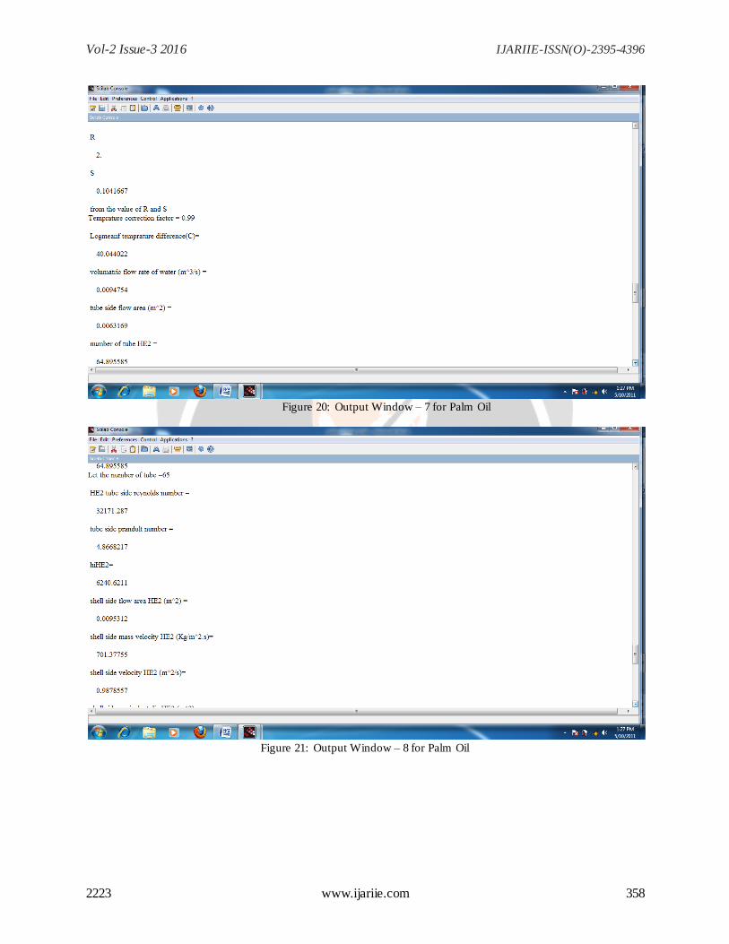
Figure 20: Output Window – 7 for Palm Oil
Figure 21: Output Window – 8 for Palm Oil
Vol-2 Issue-3 2016 IJARIIE-ISSN(O)-2395-4396
2223 www.ijariie.com 359
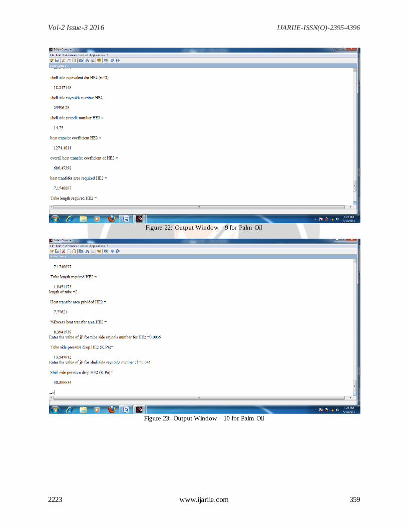
Figure 22: Output Window – 9 for Palm Oil
Figure 23: Output Window – 10 for Palm Oil