Embed Size (px)
Citation preview
107
Advances in Science and Technology Research JournalVolume 9, No. 28, Dec. 2015, pages 107–111DOI: 10.12913/22998624/60796
Research Article
Received: 2015.10.05Accepted: 2015.11.14Published: 2015.12.04
COMPUTER AIDED DESIGN OF CUTTING TOOLS
Jakub Matuszak1, Marcin Barszcz2
1 Department of Production Engineering, Mechanical Engineering Faculty, Lublin University of Technology, Nadbystrzycka 36 Str., 20-618 Lublin, Poland, e-mail: [email protected]
2 Department of Fundamentals of Technology, Technology Fundamentals Faculty, Lublin University of Technology, Nadbystrzycka 38 Str., 20-618 Lublin, Poland, e-mail: [email protected]
ABSTRACTCorrect and stable machining process requires an appropriate cutting tool. In most cases the tool can be selected by using special tool catalogs often available in online version. But in some cases there is a need to design unusual tools, for special treat-ment, which are not available in tool manufacturers’ catalogs. Proper tool design re-quires strength and geometric calculations. Moreover, in many cases specific technical documentation is required. By using Computer Aided Design of cutting tools this task can be carried out quickly and with high accuracy. Cutting tool visualization in CAD programs gives a clear overview of the design process. Besides, these programs pro-vide the ability to simulate real machining process. Nowadays, 3D modeling in CAD programs is a fundamental tool for engineers. Therefore, it is important to use them in the education process.
Keywords: cutting tools, computer aided design.
INTRODUCTION
Workstation with the appropriate software is a fundamental designing system, which, thanks to its capabilities, is able to encompass the entire process of product design, production prepara-tion, manufacturing and management together with controlling the manufacturing machines, and other devices in real time. In enterprises through internal computer networks, one project can be carried out by a larger number of design-ers who form a team, which minimizes the time from design to manufacturing the finished prod-uct and reduces the risk of errors in the design process. CAD systems that interact with CAD and CAE are programs that due to their structure allow the simultaneous work on a project of the whole team of designers. They give the oppor-tunity to introduce changes at any stage of the design, which, in turn, are automatically updated on all the team members’ computers. Advanced graphic systems allow to use the computer for presenting information to be conveniently as-
sessed and controlled by the person responsible for the project. The combination of CAD CAM allows reducing the time between design and manufacturing process. This secures quick and easy transition to the new structure and enables efficient and low-cost production of short series, and even piece production [5, 10].
Recently there has been a tendency to imple-ment additional modules into the environment of the CAD / CAM, e.g. the Finite Element Method FEM, allowing the use of advanced strength eval-uation for component models and whole assem-blies. For example, Solid Edge software allows to analyze stresses and strains, check the structure for buckling and to determine the frequency of vibrations. Advanced tools for the results visu-alization, may allow to precisely and accurately optimize the construction (for instance: to reduce weight) and evaluate the place where the parts are most strenuous.
Forming machine parts by machining process plays the leading role in the production, while cutting tools occupy the predominant position in
Advances in Science and Technology Research Journal Vol. 9 (28), 2015
108
manufacturing engineering, thanks to its wide ap-plication in industrial processes of manufacturing machine parts. Cutting tools development leads to direct development of machining centers. The introduction of new, durable tool materials, al-lows for high speed machining of materials after heat treatment. This, in turn, leads to the produc-tion of machine having the necessary rigidity, sufficient feeds and power high-speed spindles to ensure high rate of metal removal. Through this, machining can be the final step in the process of making the product. In addition to tool materi-als development of cutting tools, construction is the subject of optimization, so as to ensure maxi-mum efficiency of the cutting edge and ensure the greatest possible tool life. Tool life is important during machining of materials with high strength and hardness, like titanium and nickel alloys, be-cause the costs of cutting tools have the biggest share in the total cost of production of the prod-uct. Furthermore, it is possible to influence and control surface layer as well as the properties of the workpiece by the cutting tool [2, 4, 9].
STAGES OF THE DESIGN OF CUTTING TOOLS
Cutting tools can be divided into two groups. The first group consists of commercial cutting tools. They are used for typical machining opera-tions and the size and tool geometry are described in detail in relevant standards and catalogs. In the second group there are special tools dedicated to specific objects. The geometry and dimensions of these tools depend on the desired shape and the material of the workpiece [1, 6, 7]. In such a situation, during the design of special tools, there is a need to prepare technical documentation and perform the necessary calculations each time. De-signing cutting tools can be divided into several stages [3]:1) geometric and stereometric calculations,2) strength calculations,3) execution of tool drawings, models (3D and
2D) and simulations.
Re. 1. At this stage the assumptions associ-ated with overall dimensions of tools should be taken into account, e.g. the type and variety of tools. In the case of special forming tools, dimen-sions depend on the shape of workpiece. As for the surface roughness of the tool, it is necessary to distinguish between two important issues. The
first of these is the setup surface roughness (this is especially important for high accuracy require-ments, e.g. using heat tool holders). The second issue is the roughness of the rake and flank faces affecting the adhesive properties (e.g. during ap-plying coatings), but also built-up edge effect and the friction coefficient between the tool material and the formed chip.
Re. 2. Depending on the type of workpiece material, tool material is selected and adequate strength calculations are carried out. The calcu-lation takes into account the previously selected tool geometry and the designated force and cut-ting resistance. During machining the tool should be considered as an element that is subject to complex forces and torques. Adequate strength analysis will give the answer whether there is a risk of catastrophic tool wear. The tool wear may affect cutting edges, but also the tool body, which, in the case of indexable tools is made of less re-sistant material than the inserts. Strength calcu-lations should include a number of aspects such as mechanical strength, vibration and machining accuracy. If failure condition is not fulfilled, one should either change the tool material, or go back to step one and redesign its geometry.
Re. 3. Depending on the complexity of the tool appropriate drawings should be prepared. They can be assembly drawings for indexable tools or work in conjunction with a dedicated tool holder and working drawings fully illustrating the shape of the tool. Design solid models and then automatically generating 2D technical documen-tation is currently available in most design pro-grams such as: Solid Edge, I-DEAS, NX, T-Flex, SolidWorks, Catia ect. In addition the kinematics of machining can be simulated to illustrate the operation of the tool even better. Moreover, these programs have built-in modules for advanced rendering providing photorealistic visualization.
EXAMPLES OF COMPUTER-DESIGNED SPECIAL CUTTING TOOLS
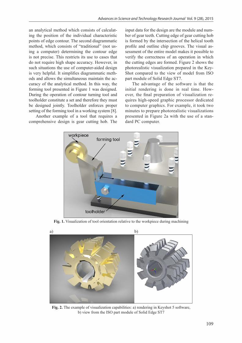
In the case of forming tools, it is very im-portant to properly determine the outline of the cutting edge. The cutting edge is reflected in the workpiece as it is shown in Figure 1. Therefore, the accuracy of the edge contour directly affects the dimensional and shape accuracy of the fin-ished object. There are two methods of determin-ing the outline of the cutting edge. The first is
109
Advances in Science and Technology Research Journal Vol. 9 (28), 2015
an analytical method which consists of calculat-ing the position of the individual characteristic points of edge contour. The second diagrammatic method, which consists of “traditional” (not us-ing a computer) determining the contour edge is not precise. This restricts its use to cases that do not require high shape accuracy. However, in such situations the use of computer-aided design is very helpful. It simplifies diagrammatic meth-ods and allows the simultaneous maintain the ac-curacy of the analytical method. In this way, the forming tool presented in Figure 1 was designed. During the operation of contour turning tool and toolholder constitute a set and therefore they must be designed jointly. Toolholder enforces proper setting of the forming tool in a working system [8].
Another example of a tool that requires a comprehensive design is gear cutting hob. The
input data for the design are the module and num-ber of gear teeth. Cutting edge of gear cutting hob is formed by the intersection of the helical tooth profile and outline chip grooves. The visual as-sessment of the entire model makes it possible to verify the correctness of an operation in which the cutting edges are formed. Figure 2 shows the photorealistic visualization prepared in the Key-Shot compared to the view of model from ISO part module of Solid Edge ST7.
The advantage of the software is that the initial rendering is done in real time. How-ever, the final preparation of visualization re-quires high-speed graphic processor dedicated to computer graphics. For example, it took two minutes to prepare photorealistic visualizations presented in Figure 2a with the use of a stan-dard PC computer.
Fig. 1. Visualization of tool orientation relative to the workpiece during machining
Fig. 2. The example of visualization capabilities: a) rendering in Keyshot 5 software, b) view from the ISO part module of Solid Edge ST7
a) b)
Advances in Science and Technology Research Journal Vol. 9 (28), 2015
110
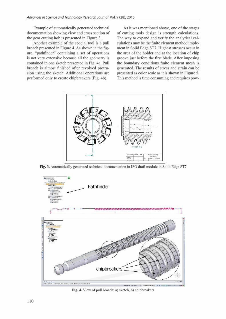
Example of automatically generated technical documentation showing view and cross section of the gear cutting hob is presented in Figure 3.
Another example of the special tool is a pull broach presented in Figure 4. As shown in the fig-ure, “pathfinder” containing a set of operations is not very extensive because all the geometry is contained in one sketch presented in Fig. 4a. Pull broach is almost finished after revolved protru-sion using the sketch. Additional operations are performed only to create chipbreakers (Fig. 4b).
Fig. 3. Automatically generated technical documentation in ISO draft module in Solid Edge ST7
Fig. 4. View of pull broach: a) sketch, b) chipbreakers
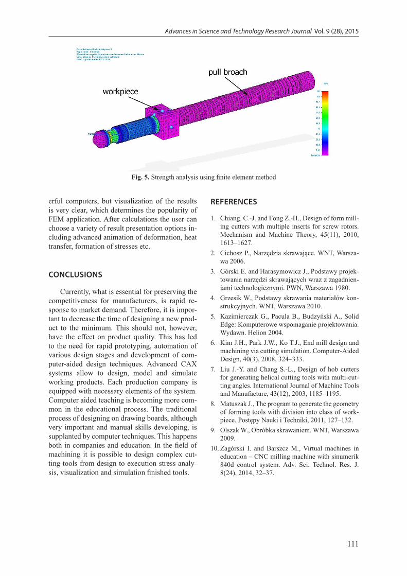
As it was mentioned above, one of the stages of cutting tools design is strength calculations. The way to expand and verify the analytical cal-culations may be the finite element method imple-ment in Solid Edge ST7. Highest stresses occur in the area of the holder and at the location of chip groove just before the first blade. After imposing the boundary conditions finite element mesh is generated. The results of stress and strain can be presented as color scale as it is shown in Figure 5. This method is time consuming and requires pow-
111
Advances in Science and Technology Research Journal Vol. 9 (28), 2015
erful computers, but visualization of the results is very clear, which determines the popularity of FEM application. After calculations the user can choose a variety of result presentation options in-cluding advanced animation of deformation, heat transfer, formation of stresses etc.
CONCLUSIONS
Currently, what is essential for preserving the competitiveness for manufacturers, is rapid re-sponse to market demand. Therefore, it is impor-tant to decrease the time of designing a new prod-uct to the minimum. This should not, however, have the effect on product quality. This has led to the need for rapid prototyping, automation of various design stages and development of com-puter-aided design techniques. Advanced CAX systems allow to design, model and simulate working products. Each production company is equipped with necessary elements of the system. Computer aided teaching is becoming more com-mon in the educational process. The traditional process of designing on drawing boards, although very important and manual skills developing, is supplanted by computer techniques. This happens both in companies and education. In the field of machining it is possible to design complex cut-ting tools from design to execution stress analy-sis, visualization and simulation finished tools.
Fig. 5. Strength analysis using finite element method
REFERENCES
1. Chiang, C.-J. and Fong Z.-H., Design of form mill-ing cutters with multiple inserts for screw rotors. Mechanism and Machine Theory, 45(11), 2010, 1613–1627.
2. Cichosz P., Narzędzia skrawające. WNT, Warsza-wa 2006.
3. Górski E. and Harasymowicz J., Podstawy projek-towania narzędzi skrawających wraz z zagadnien-iami technologicznymi. PWN, Warszawa 1980.
4. Grzesik W., Podstawy skrawania materiałów kon-strukcyjnych. WNT, Warszawa 2010.
5. Kazimierczak G., Pacula B., Budzyński A., Solid Edge: Komputerowe wspomaganie projektowania. Wydawn. Helion 2004.
6. Kim J.H., Park J.W., Ko T.J., End mill design and machining via cutting simulation. Computer-Aided Design, 40(3), 2008, 324–333.
7. Liu J.-Y. and Chang S.-L., Design of hob cutters for generating helical cutting tools with multi-cut-ting angles. International Journal of Machine Tools and Manufacture, 43(12), 2003, 1185–1195.
8. Matuszak J., The program to generate the geometry of forming tools with division into class of work-piece. Postępy Nauki i Techniki, 2011, 127–132.
9. Olszak W., Obróbka skrawaniem. WNT, Warszawa 2009.
10. Zagórski I. and Barszcz M., Virtual machines in education – CNC milling machine with sinumerik 840d control system. Adv. Sci. Technol. Res. J. 8(24), 2014, 32–37.