Embed Size (px)
Citation preview
AD-A233 834 0ry "/1,71¢
NASA AVSCOMTechnical Memorandum 101449 Technical Memorandum 88-C-005
Computer-Aided Design of BevelGear Tooth Surfaces
Shuo Hung ChangIBM T.J. Watson Research CenterYorktown Heights, New York
Ronald L. HustonUniversity of Cincinnati "Cincinnati, Ohio A.
and , i'.ii
John J. CoyLewis Research CenterCleveland, Ohio
Prepared for theFifth International Power Transmission and Gearing Conferencesponsored by the American Society of Mechanical EngineersChicago, Illinois, April 25-27, 1989
US ARMYAVIATIONSYSTr*AS COMMAND
AVIATION R&T ACTIVITY
S : 91 •, 22 065
DISCLAIMER NOTICE
\ \
THIS DOCUMENT IS BEST
QUALITY AVAILABLE. THE COPY
FURNISHED TO DTIC CONTAINED
A SIGNIFICANT NUMBER OF
PAGES WHICH DO NOT
REPRODUCE LEGIBLY.
COMPUTER-AIDED DESIGN OF BEVEL GEAR TOOfH SURFACES
Shuo Hung ChangIBM T.J. Watson Research Center
P.O. Box 218, 71-A15 -
Yorktown Heights, New York 10598
Ronald L. Huston* ')Department of Mechanical and Industrial Engineering . " fl
University of CincinnatiCincinnati, Ohio 45221-0072
' ' . .. .. . .. . . .
and
John J. Coy .wr. .National Aeronautics and Space Administration
Lewis Research Center ....
Cleveland, Ohio 44135-3191
SUMMARY
'This Daper presents a computer.'aided design procedure for generating bevelgears. The development is based on examining a perfectly plastic, cone-shapedgear blank rolling over a cutting tooth on a plane crown rack. The resulting
c impression on the plastic gear blank is the envelope of the cutting tooth.SThis impression and envelope thus form a conjugate tooth surface. Equations, are presented for the locus of points on the tooth surface. The same proce-
dures are then extended to simulate the generation of a spiral bevel gear.The corresponding governing equations are presented. .. , 4" ,
INTRODUCTION
Bevel gears are the principle means of motion and power transmissionbetween intersecting shafts. Their use is widespread. The geometrical cha-racteristics of bevel gears have long been documented by the American GearManufacturers' Association (AGMA, 1964) and others (Dudley, 1962; Dyson, 1969;Bonsignore, 1976; Litvin et kl., 1975, 1982, 1983: Baxter, 1966; Huston andCoy, 1981,1982a,b). Recent advances in computer-aided design present opportu-nities for a new look at the geometry of these gears. These computer-basedprocedures also provide a means for optimizing the geometry.
In a previous paper (Chang, Huston, and Coy, 1984) we have demonstratedthe feasibility of this procedure to determine a spur gear tooth profile. Thebasic idea was to use the envelope of a family of curves to develop an invo-lute spur gear tooth profile. The study demonstrated that the envelope of aninclined straight-line segment on a rolling gear blank is an involute of a cir-cle, The inclined line segment in turn represented the rack tooth of a hobcutter. Such a procedure provides a means for analytically and numericallydetermining the tooth profile, given a cutter profile.
*Work funded under NASA Grant NAG3-188.
In the current paper we extend these ideas to the generation of bothstraight and spiral bevel gears. The paper itself is divided into four sec-tions with the section following the Symbols providing preliminary ideas use-ful in this sequel. lhe next two sections describe the formulation of stringand spiral bevel gear tooth surfaces. This is followed by a discussion ofapplications.
SYMBOLS
The following symbols are used in the section for development of a
straight bevel gear tooth.
Rm Mean radius of crown gear in pitch plane
[R) Coordinate transformation matrix; from § to S
ER1) Coordinate transformation matrix; from S1 to S
ER2) Coordinate transformation matrix; from S2 to Sl
[R3) Coordinate transformation matrix; from S to S2
Position vector in S
rg Position vector in
rij Components of (R]
S(X,YZ) Cartesian coordinate system stationary with ground
t (M,,Z) Cartesian system stationary with generated gear
SI(XI,YI,ZI) Intermediate Cartesian coordinate system
S2 (X2 ,Y 2 ,Z 2 ) Intermediate Cartesian coordinate system
Xp Projection of X axis on crown gear pitch plane
CL Angular position of gear referenced to system S
OL0 Initial aigular position of gear
y Pitch angle of pinion
e Angle of rotation of generated gear
Complement of pressure angle of cutter
Cutter's orientation angle on pitch plane
The following symbols are used in the section for development of a spiral
bevel gear tooth.
B Derivative of T with respect to 02
2
bi Components of
dij 8eij/3ý2
[E] Coordinate transformation matrix; from S2 to Sr
eij Components of [E]
H Horizontal machine setting of cutter
h Addendum of cutter tooth (pitch to tip)
Ng Number of teeth in crown gear
Np Number of teeth in generated gear
ERcI] Coordinate transformation matrix; from Si to Sc
[Rig] Coordinate transformation matrix; from Sg to Si
[Rgp) Coordinate transformation matrix; from Sp to Sg
[Rp2] Coordinate transformation matrix; from S2 to Sp
rc Mean radius of cutter in pitch plane
Fc Position vector in Sc
rg Position vector in Sg
rp Position vector in Sp
71 Position vector in S1
: 2 Position vector in S2
Sc(Xc,YcZc) Cartesian coordinate system stationary with cutter with origin
at 0 c
SI(XI,YI,ZI) Cartesian coordinate system stationary with gear with origin
at 01
S2 (X2 ,Y2 ,Z 2 ) Cartesian coordinate system stationary with pinion with
origin at 02
Sg(Xg,Yg,Zg) Cartesian coordinate system stationary with ground with
origin at 0g
Sp(Xp,Yp,Zp) Cartesian coordinate system stationary with ground with origin
at Op
Coordinate translation transformation matrix: from S2 to Sc
3
TIc Coordinate translation transformation matrix: from Sc to $i
Tgp Coordinate translation transformation matrix; from Sp to Sg
ti Components of T
V Vertical machine setting of cutter
w Angular speed ratio
ZO Zc intercept of cutter surface
r Surface coordinate of cutter
y Root angle of pinion
YO Pitch angle of pinion
e Angle of rotation of system Sc reference to SI
01 Angle of rotation of gear
$2 Angle of rotation of gear blank
$10 Initial angular position of gear
'*0 Complement cf pressure angle of cutter edge
Cg Rotation rate of gear
Wp Rotation rate of pinion
ENVELOPE OF A FAMILY OF SURFACES
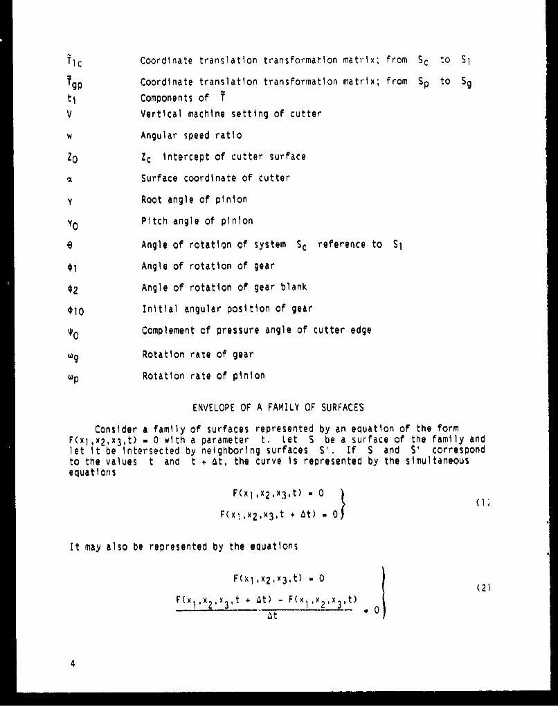
Consider a family of surfaces represented by an equation of the formF(xl,x 2 ,x 3 ,t) w 0 with a parameter t. Let S be a surface of the family andlet it be intersected by neighboring surfaces S'. If S and S' correspondto the values t and t + At, the curve is represented by the simultaneousequations
F(x 1 ,x 2 ,x 3 ,t) O 0
F(xl,x 2 ,x 3 ,t + 6t) a 0)
It may also be represented by the equations
F(xl,x2,x 3 ,t) = 0(2)
F(x ,x2 ,x 3 ,t + At) - F(x1 ,x2 1x3 ,t)at
4
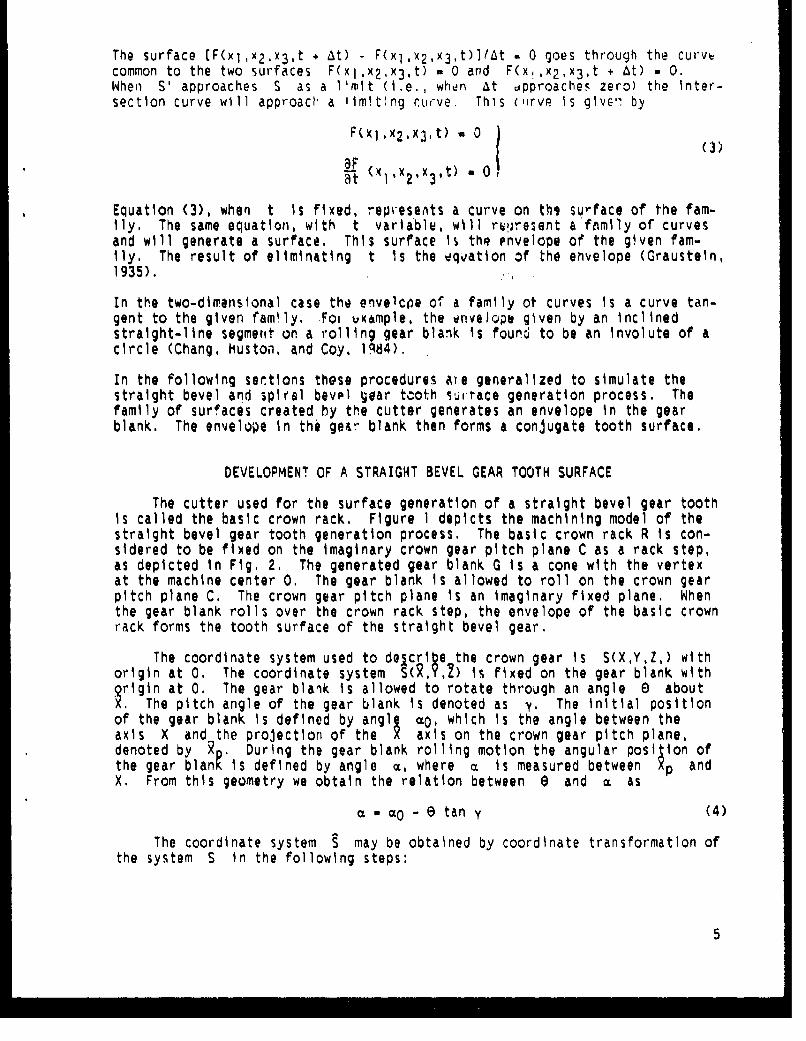
The surface [F(xl,x 2 .x 3 ,t + At) - F(xl,x2,x 3 ,t)]/At - 0 goes through the curvecommon to the two surfaces F(xl,x 2 ,x3,t) - 0 and F(x1,x 2 ,x 3 ,t + At) - 0.When S' approaches S as a l'mit (i.e,, when At approaches zero) the inter-section curve will approach, a limiting C.uve. This (urve is glve-, by
F(xlx 2 ,x 3 ,t) a 0 (3)8F 0 1 Iat (XlX 21X31't) - 0
Equation (3), when t is fixed, repveseAts a curve on thi surface of the fam-ily. The same equation, with t variable, wll r•present a family of curvesand will generate a surface. This surface i$ thq envelope of the given fam-ily. The result of eliminating t is the dquation of the envelope (Graustein,1935).
In the two-dimensional case the envelcoe of a family ot curves is a curve tan-gent to the given family. Foi example, the envelope given by an inclinedstraight-line segmetit on a rolling gear blank is found to be an involute of acircle (Chang, Huston, and Coy, 1984).
In the following sections these procedures ate generalized to simulate thestraight bevel and spival bevel gear tcoth surtace generation process. Thefamily of surfaces created by the cutter generates an envelope in the gearblank. The envelope in the geor blank then forms a conjugate tooth surface.
DEVELOPMENT OF A STRAIGHT BEVEL GEAR TOOTH SURFACE
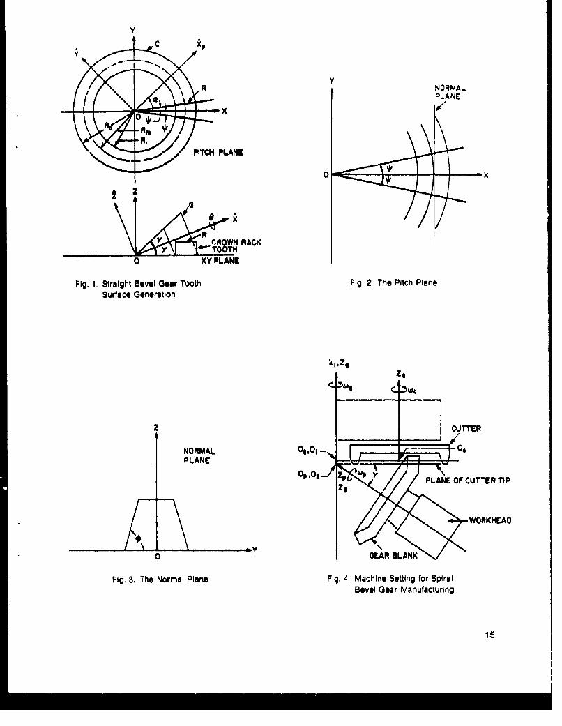
The cutter used for the surface generation of a straight bevel gear toothis called the basic crown rack. Figure 1 depicts the machining model of thestraight bevel gear tooth generation process. The basic crown rack R is con-sidered to be fixed on the imaginary crown gear pitch plane C as a rack step,as depicted in Fig. 2. The generated gear blank G is a cone with the vertexat the machine center 0. The gear blank Is allowed to roll on the crown gearpitch plane C. The crown gear pitch plane is an imaginary fixed plane. Whenthe gear blank rolls over the crown rack step, the envelope of the basic crownrack forms the tooth surface of the straight bevel gear.
The coordinate system used to delcri e the crown gear Is S(X,Y,Z,) withorigin at 0. The coordinate system S(, Y,b) is fixed on the gear blank withQrigin at 0. The gear blank is allowed to rotate through an angle 0 aboutX. The pitch angle of the gear blank is denoted as y. The initial positionof the gear blank is defined by angl c0, which is the angle between theaxis X and the projection of the X axis on the crown gear pitch plane,denoted by . During the gear blank rolling motion the angular posi ion ofthe gear blan•'is defined by angle a, where a is measured between Xp andX, From this geometry we obtain the relation between e and a as
a w 0 - e tan y (4)
The coordinate system S may be obtained by coordinate transformation ofthe system S in the following steps:
5
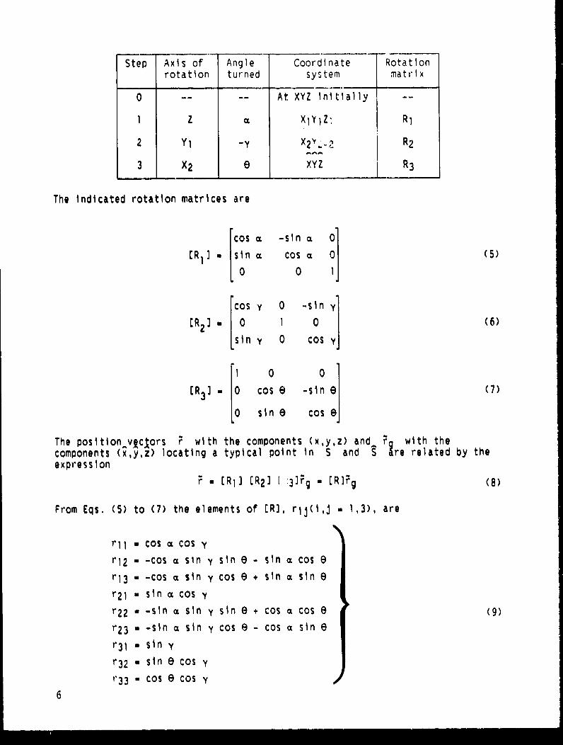
Step Axis of Angle Coordinate Rotation
rotation turned system matrix
0 -- At XYZ initially
I Z XIYIZ" RI
2 Yl -Y X2 R2
3 X2 e XYZ R3
The indicated rotation matrices are
[COS C -sin~ (z ]ER1 I [ -sin a COS 0 (5)
cos y 0 -sin y]
ER 2). 0 1 0 j(6)1 sin y 0 COS Y
1 0 0
ER3 )1 0 cos e -sine (7)
0 sine Cose
The position v clors ' with the components (x,y,z) and, a with thecomponents (x,y,z) locating a typical point in S and S re related by theexpression
F E [R 1) [R2) ( 3]Fg - [R1Fg (8)
From Eqs. (5) to (7) the elements of ER), rij(i,j . 1,3), are
rll1 cos a Cos y
r12 - -cos a sin y sin e - sin a cos 8
r 1 3 a -cos a sin y Cos 9 + sin x sin e
r 2 l w sin a cos y
r22 •-sin m sin y sin e + cos a cos e (9)
r23 • -sin a sin y Cos e - cos a sin e
r 31 - sin y
r 3 2 - sin e cos y
r 3 3 a cos E cos y
6
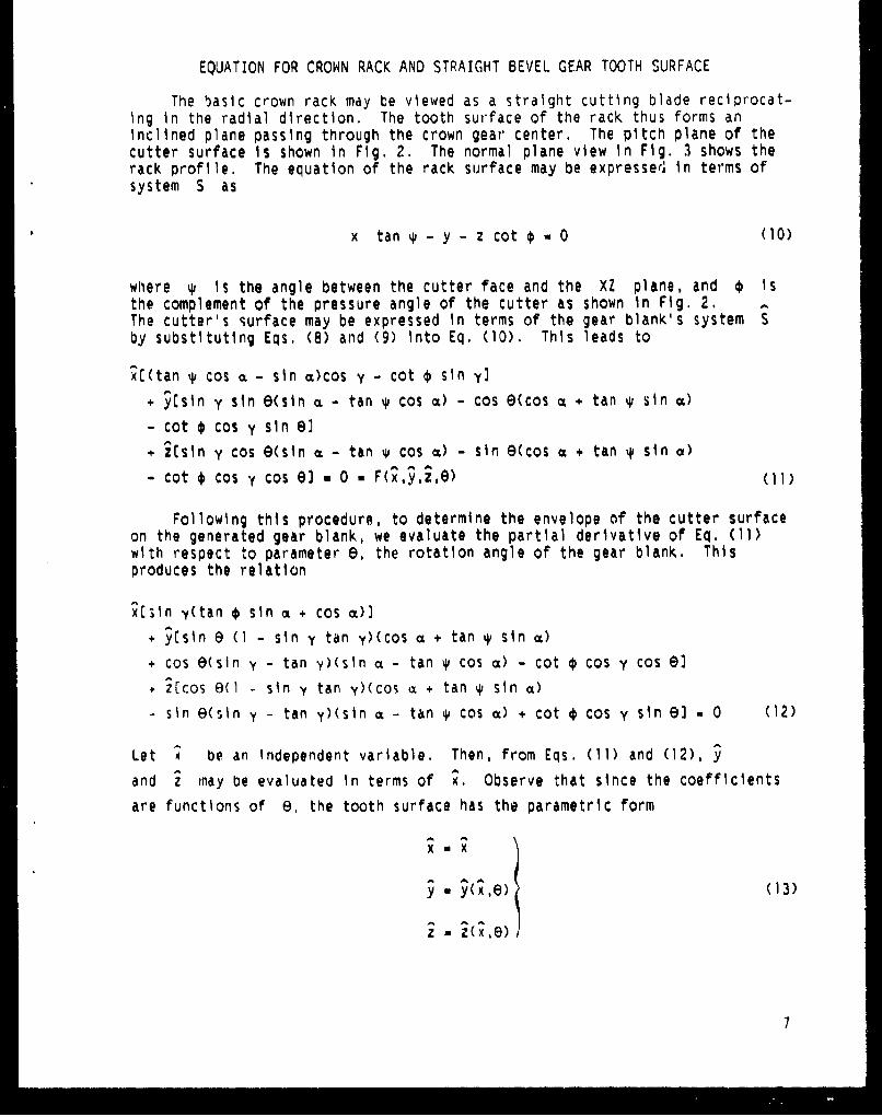
EQUATION FOR CROWN RACK AND STRAIGHT BEVEL GEAR TOOTH SURFACE
The basic crown rack may be viewed as a straight cutting blade reciprocat-ing in the radial direction. The tooth surface of the rack thus forms aninclined plane passing through the crown gear center. The pitch plane of thecutter surface is shown in Fig. 2. The normal plane view in Fig. 3 shows therack profile. The equation of the rack surface may be expresser, in terms ofsystem S as
x tan N - y - z cot * * 0 (10)
where q1 is the angle between the cutter face and the XZ plane, and * Isthe complement of the pressure angle of the cutter as shown in Fig. 2.The cutter's surface may be expressed in terms of the gear blank's system Sby substituting Eqs, (8) and (9) Into Eq. (10). This leads to
x[(tan q' cos • - sin a)cos y - cot * sin y]
+ y[sin y sin esin a - tan %p cos () - cos e(cos % + tan % sin ot)
- cot * cos y sin el
+ 2isin y cos e(sin ( - tan y cos %) - sin 9(cos a + tan %# sin a)
- cot * cos y cos 6) 0. (11)
Following this procedure, to determine the envelope of the cutter surfaceon the generated gear blank, we evaluate the partial derivative of Eq. (11)with respect to parameter e, the rotation angle of the gear blank. Thisproduces the relation
x[[in y(tan * sin a + cos m)]
"+ y[sin 9 (1 - sin y tan y)(cos a + tan + sin •)
"÷ cos 0(sin y - tan y)(sin a - tan 4 cos a) - cot € cos y cos 9)
"÷ i[cos @(I - sin y tan y)(cos a + tan N sin c)
- sin e(sin y - tan y)(sin ( - tan 4# cos c) + cot € cos y sin e9 = 0 (12)
Let • be an independent variable. Then, from Eqs. (11) and (12), y
and i may be evaluated in terms of ;. Observe that since the coefficients
are functions of e, the tooth surface has the parametric form
X X
ý W .(13)
7
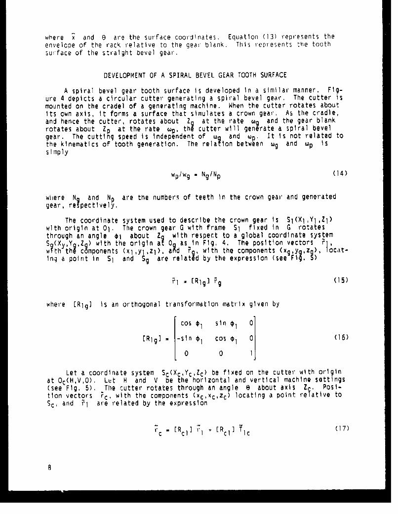
where x and E are the surface coordinates. Equation (13) represents theenvelcpe of the rack relative to the gear blank. This renresents the toothsurface of the straight bevel gear.
DEVELOPMENT OF A SPIRAL BEVEL GEAR TOOTH SURFACE
A spiral bevel gear tooth surface Is developed in a similar manner. Fig-ure 4 depicts a circular cutter generating a spiral bevel gear. The cutter Ismounted on the cradel of a generating machine. When the cutter rotates aboutits own axis, it forms a surface that simulates a crown gear. As the cradle,and hence the cutter, rotates about Z at the rate Wg and the gear blankrotates about Zp at the rate wp, thA cutter will generate a spiral bevelgear. The cutting speed is independent of wa and wp. It is not related tothe kinematics of tooth generation. The rela ion between Wg and Up issimply
Wp/Wg - Ng/Np (14)
whiere N and Np are the numbers of teeth in the crown gear and generatedgear, relpectively.
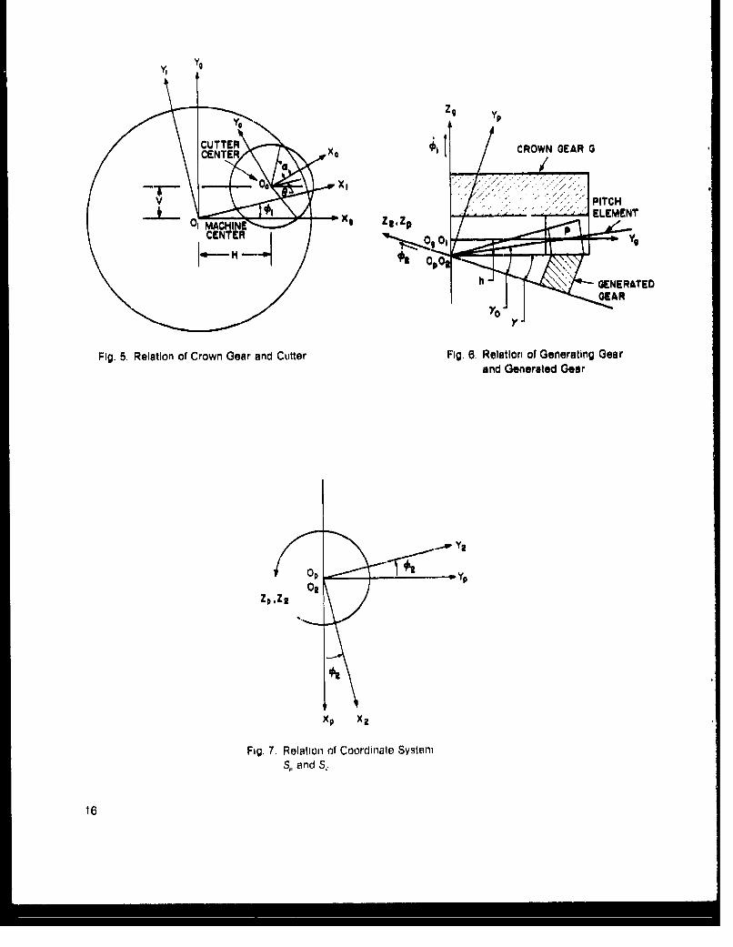
The coordinate system used to describe the crown gear Is SI(XI,YI,Zl)with origin at 01. The crown gear G with frame $1 fixed in G rotatesthrough an angle $1 about Z with respect to a global coordinate system
(X,YQZg) with the origin aý 0 as in Fig, 4. The position vectors rj,whthy thecomponents (xlYlZl), ahd r , with the components (xg,yýzQ ), ocat-Ing a point in $1 and Sg are relat d by the expression (see Fig, 5)
Fl - [Rlg) Fg (15)
where [Rlg] is an orthogonal transformation matrix given by
Cos 01 sin 0l
[Rig] a -sin 0, cos I 0 (16)
0 0
Let a coordinate system Sc(Xc,Yc,Zc) be fixed on the cutter with originat Oc(H,V,O). Let H and V be the horizontal and vertical machine settings(see Fig. 5). The cutter rotates through an angle e about axis Z Posi-tion vectors ýc, with the components (xc,xc,zc) locating a point relative toSc, and r1 are related by the expression
rc [Rcl) rI + [Rc 1 ] Tlc (17)

where [RIJ] and Tic are
[cose sine 0)
CRi C1 1-sine0 cose0 0 (18)
0 0 1
and
H
T1c • (19)
0
Let the coordinate system S2(X2,Y2,Z 2 ) be fixed in the gear blank. LetS2 rotate through an angle *2 about ZP with respect to a second globalcoordinate system Sp(Xp, Y .Zo) (see Figs. 4, 6, and 7). The position vec-tors ? with the componehts (Xp,Yp,Zo), and 72, with the components(x2,Y2,32), locating a point in Sp ahd S2 are related by the expression
?p - ERp2] F2 (20)
where the transformation matrix ERp2) from S2 to Sp is given by
Cos ý2 -sin *2 0
ERp2 3 .sin ý2 Cos ý2 0 (21)
0 0 1
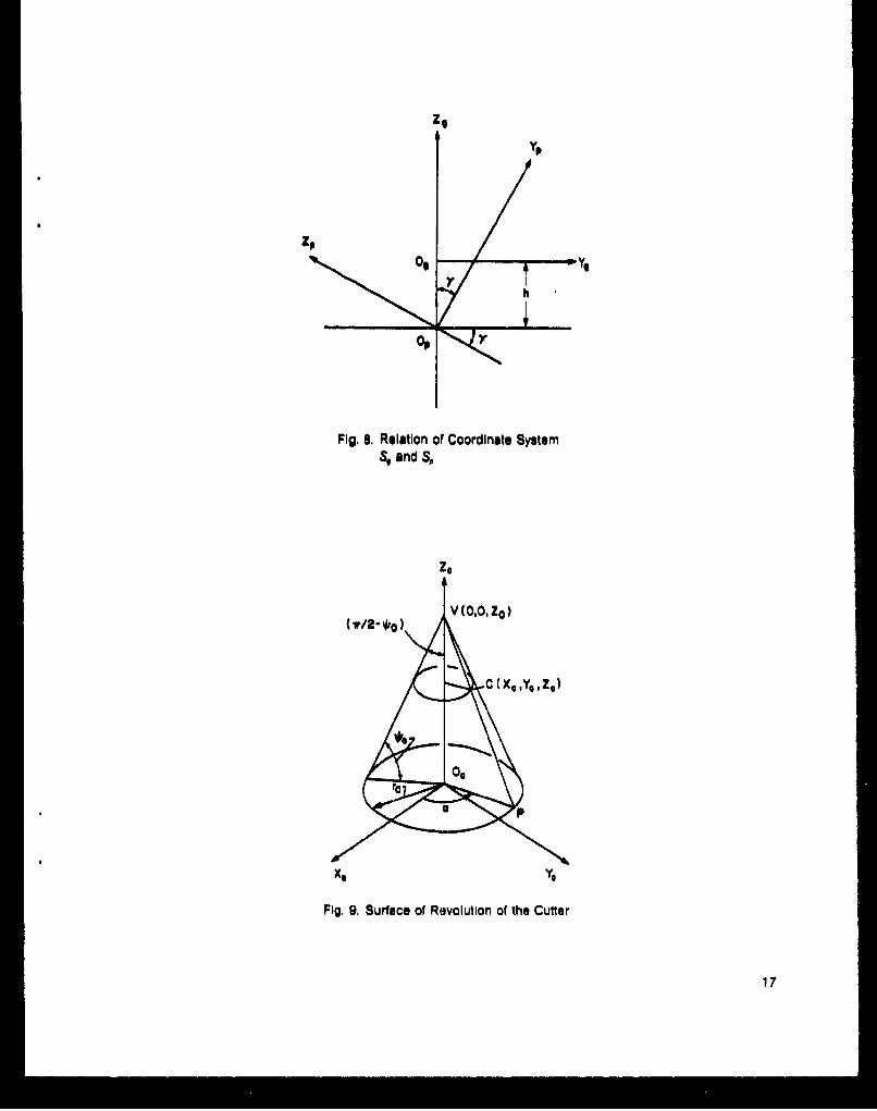
The two global coordinate systems S and S are related by the rootangle y of the generated gear and the ade ndum o• the cutter tooth h (seeFigs. 4, 6, and 8.) Hence, rg and 7p are related by the expression
?9 ER gp]Fp + Tgp (22)
where
1 0 0
[Rg 9P1[ sin y -cos y (23)
0 cos y sin y
and
9
Ig [ (24)
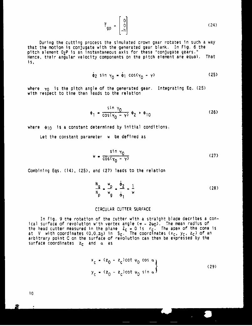
During the cutting process the simulated crown gear rotates in such a waythat the motion is conjugate with the generated gear blank. In Fig. 6 thepitch element 02P is an instantaneous axis for these "conjugate gears."Hence, their angular velocity components on the pitch element are equal, Thatis,
ý2 sin YO - $1 cos(y 0 - Y) (25)
where yo is the pitch angle of the generated gear. Integrating Eq. (25)with respect to time then leads to the relation
s in y o2O
Scos(Yo - y) 2 + €10 (26)
where co is a constant determined by initial conditions.
Let the constant parameter w be defined as
W sin - (27)cos(Yo - y)
Combining Eqs. (14), (25), and (27) leads to the relation
N w 1_q1!p ! (28)Np w g ýI w
CIRCULAR CUTTER SURFACE
In Fig. 9 the rotation of the cutter with a straight blade decribes a con-ical surface of revolution with vertex angle (O - 2%y0). The mean radius ofthe head cutter measured in the plane Zc = 0 Is re, The apex of the cone isat V with coordinates (O,0,zO) in Sc. The coordinates (Oc, Yc, Zc) of anarbitrary point C on the surface of revolution can then be expressed by thesurface coordinates zc and a as
xc " (z0 - zc)cot %Y0 cos (
YC " (z0 - z c )cot sin
10
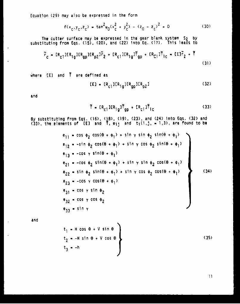
Equation (29) may also be expressed In the form
f(xcYczc) Y tan2 0 (x + 2) -(z 0 zc) 2 - 0 (30)
The cutter surface may be expressed in the gear blank system S2 bysubstituting from Eqs. (15), (20), and (22) Into Eq. (17), This leads to
rc " [R cl] R g[Rgp ]Rp2]3 2 + [Rcl]IRIg]Tgp + [RclIT Ic - [Eýr2 +
(31)
where tE) and T are defined as
EEJ = E%1 )ERl[g][RgpJIRp 2 ] (32)
and
= [Rc1I3R gITgp + tR clifc (33)
By substituting from Eqs. (16), (18), (19), (23), and (24) Into Eqs. (32) and(33), the elements of CE] and Y, eij and ti(i,j, w 1,3), are found to be
e011 cos ý2 cos(e + + sin y sin 02 sin(e + s1)
e12 = -sin ý2 cos(e + 1) + sin y cos *2 sin(e + 01)
e 13 - -cos -y stn(e + 1
e 21 n -cos 02 sin(e + 01) + sin y sin 02 cos(e + 01)
e22 0 sin 02 sin(e + 01) + sin y cos 02 cos(e + 1)34)
e23 - -Cos y cos(e + 0i)
e31 - cos y sin 02
e32 = Cos y Cos 02
e 33 a sin y
and
tI = H cos e + V sin e
t2 * -H sin e + V cos e (35)
t3 = -h
11
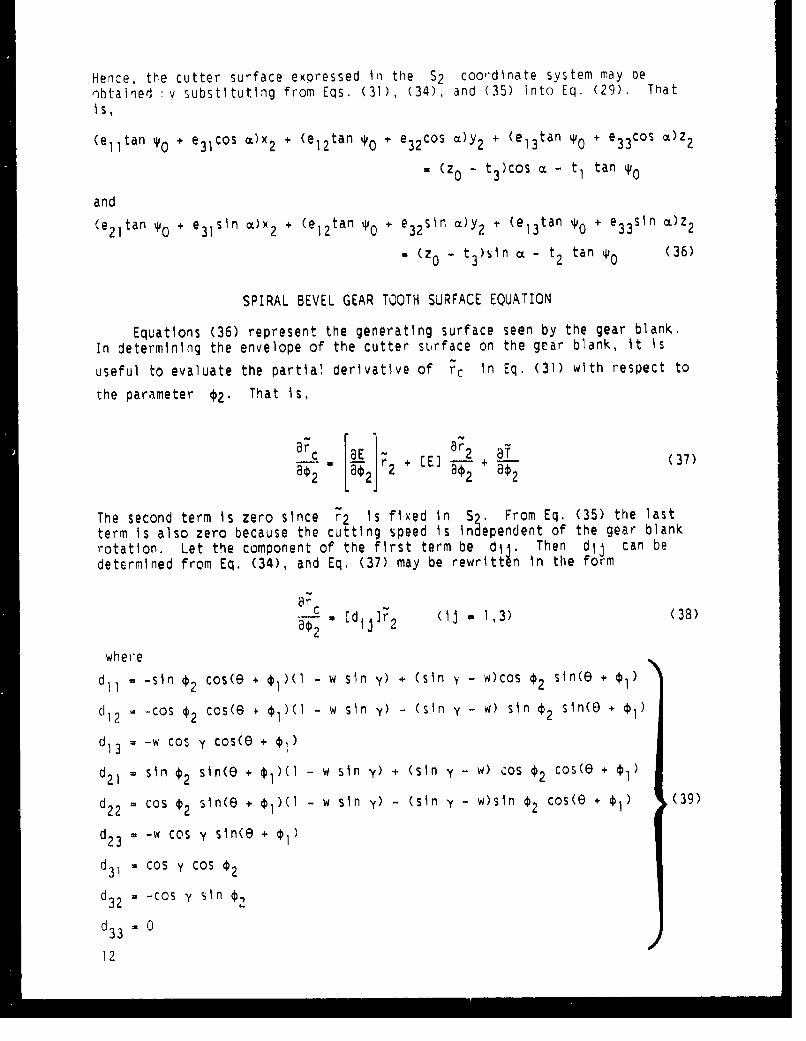
Hence, the cutter surface expressed in the S2 coordlinate system may benbtained :v substituting from Eqs. (31), (34), and (35) into Eq. (29). ThatIs,
(e 11tan Yo + e3 1cos m)x2 + (e 12tan %0 + e32 cos cL)Y 2 + (e 13tan w0 + e3 3cos M)Z2
(z 0 - t 3 )cos a - tl tan %0
and
(e 2 1tan ,0 + e 3 1sln a)x 2 + (el2tan %0 + e32 sIn a)y 2 + (el3tan it0 + e3 3 s O)z 2
- (z 0 - t 3 )sin a - t 2 tan *0 (36)
SPIRAL BEVEL GEAR TOOTH SURFACE EQUATION
Equations (36) represent the generating surface seen by the gear blank.In determining the envelope of the cutter surface on the gear blank, it is
useful to evaluate the partial derivative of ýc in Eq. (31) with respect to
the parameter *2. That is,
ac [LE[E] a r2 ÷ (37)
aý2 [02 jý O
The second term Is zero since r2 is fixed in S2, From Eq. (35) the lastterm is also zero because the cutting speed is independent of the gear blankrotation. Let the component of the first term be dj . Then dij can bedetermined from Eq. (34), and Eq. (37) may be rewritt~n in the form
30 d r2 (lj . 1,3) (38)
where
d - -sn *2 cos(e * 01)(1 - w sin y) + (sin y - w)cos *2 sin(8 + 01)
dI12 - -cos ¢2 cos(" + *i)(I - w sin y) - (sin y - w) sin ¢2 sin(E) + (i)
d1 3 - -w cos y cos(e + 0i)
d21 = sin 02 sin(e + 01)(I - w sin y) + (sin y - w) cos 02 cos(e + 01)
d2 2 - cos ý2 sin(e + i)(l - w sin y) - (sin y - w)sin ý2 cos(e + (39)
d2 3 -w cos y sIn(e +
d 31 Ccos y COS €2
d32 -cos y sin €,
d233 0
12
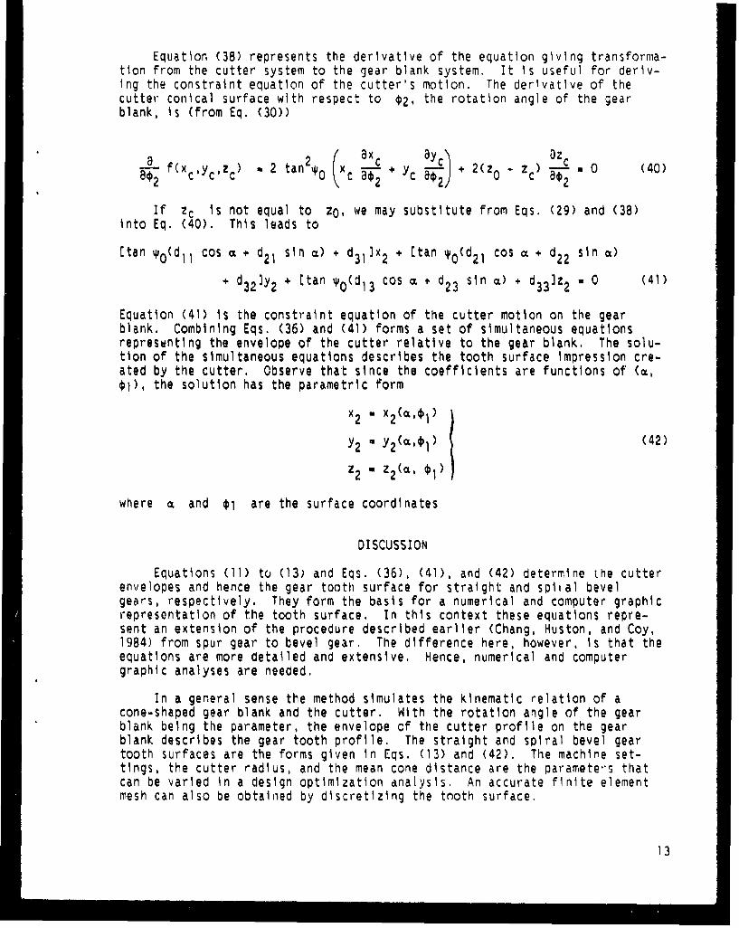
Equation (38) represents the derivative of the equation giving transforma-tion from the cutter system to the gear blank system. It is useful for deryv-Ing the constraint equation of the cutter's motion. The derivative of thecutter conical surface with respect to *2, the rotation angle of the gearblank, is (from Eq. (30))
Lf~ yX :~.vz ) m 2 tan 2 Y x!X-C + yc + 2(z0 - ~) ! 0 (40)__0a2 fc c'c ) . 2 tan2, N c 802; 0 " cIf zc is not equal to zO, we may substitute from Eqs. (29) and (38)
into Eq. (40). This leads to
[tan yo(dll cos a + d2 1 sin 0) + d3 1]x 2 + [tan # 0(d 2 1 cos a + d2 2 sin •)
+ d32 ]Y2 + [tan yO(d 13 cos o + d2 3 sin m) + d3 3 ]z2 - 0 (41)
Equation (41) is the constraint equation of the cutter motion on the gearblank. Combining Eqs. (36) and (41) forms a set of simultaneous equationsrepresenting the envelope of the cutter relative to the gear blank. The solu-tion of the simultaneous equations describes the tooth surface impression cre-ated by the cutter. Observe that since the coefficients are functions of ((X,*1), the solution has the parametric form
x2- x2( ,4l)
Y 2 (•I) 2 (42)
z2 - z2 (a, 0i)
where • and 0l are the surface coordinates
DISCUSSION
Equations (11) to (13) and Eqs. (36), (41), and (42) determine the cutterenvelopes and hence the gear tooth surface for straight and spital bevelgears, respectively. They form the basis for a numerical and computer graphicrepresentation of the tooth surface. In this context these equations repre-sent an extension of the procedure described earlier (Chang, Huston, and Coy,1984) from spur gear to bevel gear. The difference here, however, is that theequations are more detailed and extensive. Hence, numerical and computergraphic analyses are needed.
In a general sense the method simulates the kinematic relation of acone-shaped gear blank and the cutter. With the rotation angle of the gearblank being the parameter, the envelope of the cutter profile on the gearblank describes the gear tooth profile. The straight and spiral bevel geartooth surfaces are the forms given in Eqs. (13) and (42). The machine set-tings, the cutter radius, and the mean cone distance are the paramete's thatcan be varied in a design optimization analysis. An accurate finite elementmesh can also be obtained by discretizing the tnoth surface.
13
In summary, it Is believed by the authors that the analysis presentedherein can form a basis for numerical desigr stuDies av well as for stress anddeformation studies, Finally, the method may he -eadily extended to the studyof nonintersecting shaft (hypoid) gears.
REFERENCES
AGMA, 1964, "Standard System for Spiral Bevel Gears," AGMA Publication 209.03,American Gear Manufacturers As:ociation, Alexano-ia, VA.
Baxter, M.L, Jr., 1966, "Exact Determination of tooth Surfaces for SpiralBevel and Hypoid Gears," AGMA Paper 130.02, American Gear ManufacturersAssociation, Alexandria, VA.
Bonsignore, A.T., l•16, "The Effect of Cutter Diameter on Spiral Bevel ToothProportions," AGMA Paper 124.20, American Geat Manufacturers Association,Alexandria, VA.
Chang, S.H., Huston. RL., and Coy, J.J., 1984, "A Computer Aided Design
Procedure for Generating Gear Teeth," ASME Paper 84-DET-184.
Dudley, D.X,, 1963, Gear Handbook, McGraw-Hill, New York.
Dyson, A., 1969, A General Theory of the Kinematics and Geometry of Gears inThree Dimensions, Clarendon Press, Oxford.
Graustein, N.C., 1935, Differential Geometrj, McMillan, New York, p. 64.
Huston, R.L. and Coy, J,J., 1981, "Ideal Spiral Bevel Gears - A New Approachto Surface Geometry," Journal of MechanIcal Desjgn, Vol. 103, No. 1,pp. 127-133.
Huston, R.L. and Coy, J3J., 1981, "A Basis for the Analysis of SurfaceGeometry of Spiral Bevel Gears," Advanced Power Transmission Technology,G.K. Fischer, ed., NASA CP-2210, pp. 49-77.
Husto'i, R.L. and Coy, J.J., 1982, "Surface Geometry of Circular Cut SpliralBevel Gears," Journal of Mechanical Desigg, Vol. 104, No. 4, pp. 743-748,
Husto, R.L., Lin, Y., and Coy, J.J., 1983, "Tooth Profile Analysis ofCircular-Cut, Spiral-Bevel Gears," Journal oF Mechanisms Transmissions,and Automation in Design, Vol. 105, No. I, pp. 132-137.
Litvin, F.L., Krylov, N.N., and Erickhov, M.L., 1975, "Generation of ToothSurfaces by Two-Parameter Enveloping," Mechanism and MachineTheory,Vol. 10, No. 5, pp. 365-373.
Litvin, F.L., Rahman, P., and Goldrich, R.N., 1982, 'Mathematical Methods forthe Synthesis and Optimization of Spiral Bevel Gear Tooth Surfaces," NASACR-3553.
Litvin, F.L., Goldrich, R.N., Coy, J.J., and Zaretsky, E.V., 1983, "Precisionof Spiral Bevel Gears," Journal of Mecharics Trans:issior. and Automa-tion in Ueslign, Vol. 105, No. 3, p , 310-3' .
14
Y
CY
R NORMALPLANE
0 * x
PITCHPLAE -/ Z/PIA"EFcurRTP
0 Y PLANE RC
Fig. 1. Straight Bevel Gear Tooth Fig. 2. The Pitch PlaneSurface Generation
ze
zZ CUTTER
NORMAL OISO,01 0,
Op loo~ p r PLANE OF CUTTER TIPZa
~~~~.WORMMEAD
0 nU I
Fig. 3. The Normal Plane Fig. 4 Machine Setting for SpiralBevei Gear Manufacturing
CUTE Z CROWN GEAR G
CENTENERRE
op p*2
*22
XP 2
Fig. 7. Relation of Coordinale SysteniS, and S,
16
Zo
yp
zpof ye
h
Fig. 8, Relation of Coordinate Systema, end S,
ze
V (o0., Zo)
C CX4,YOzI)
00
a p
Fig. 9. Surface of Revolution of the Cutter
17
Ndwo i Ae.. a ic,.-C A- Report Documentation Page.ReotNo NAAGo014 ~vernment AccE .sion No* f Recipient sCatalog No.
AVSCO)N TM-Mg-C-11()154. Title and Subtitle 5. Repan Date
Computer-Aided Design of Bevel Gear Tooth Surfaces6. Performing Organization Code
7. Author(s) a. Performing Organization Report No.
Shuo Hung Chang, Ronald L. Huston, and John 3. Coy E-4558
- -_____________10. Work Unitl No.0. Performing Organization Name and Address 505-63-51
NASA Lewis4 Research Center I L I 62209A47AClevland Ohi 4415-311it. Contract or Grant No.and
Propulsion DirectorateUS, Army Aviation Research and Technology Activity-AVSCOM ________
Clevelatnd, Ohio 44135-3127 13. Type of Report and Period Coveredill. Sponsoring Agenriy Name and Address Technical Memorandum
National Aeronauticx and Space AdministrationWashington, D.C. 20546-O00I 14. Sponsoring Agency CodefindU.S. Army Aviation Systems ComnmandSt. Louis, Mo. 63120-1798
I15. Supplementary Notes
IPrelmitil for tlit Fiflh Internationai Power Tranfinitiisslon and! Clearing Crinference sponmired by the Amrerican Society of Mechanivi nol ngincri.(hiciigo, Illinois, April 23-27, 19N'9. Shuo Hung Chang, IBM TIJ. Watsxon Reicar':h Center, P.O. tBox 218, 71-AI5. Yorktown Heights,Ne% York 10398- Notiald L. Huston. Dept. or Mec~hanical and Industrial Engineering, University or Cinviniiati, Cincinnati, Ohio 45221-0072twilik flinded tinder NASA Grant NAU31-111i: John J. Coy, NASA Lowis Restearch Canter.
1i6 AbsitraictI
This paper presents a computer-aided design procedure for generating bevel gears. The development is based onexatnining a perf'ectly plastic, cone-shaped gear blank rolling over a cutting tooth on at plane crown rack, Therosulting impression onl the plastic gear blank is the envelope (if the cutting tooth, This Impression and enivelopethus fornm a conjugatle tooth surface. Equations are presented for the locus of points on the tooth surface. Tilesnime procedures are then extendied ito simulate the generation of it spiral bevel gear. The corresponding governingequations are presecnted.
11. Key Words (Suggested by Author(s)) 16. Distribution Statement
D)ifferential gcotiltry; Comiputer-aided design, Gears; Unclassified - UnlimitedMachitne design; Bevel gears Sub~ject Category 37
19. Security Ciemnaf. (of this report) 20. Security Ciasaif. lof this page) 21t No of pages 122. Price.Unclassified IUnclassified 18 A 0.
NAIA PoRNIi 61 OC 'For sale by the National Technical Information Service. Spr-nolielid. Virginia 22161