Embed Size (px)
Citation preview

1
Computer Aided Design (CAD)
Computer Aided Design is the use of computer technology for the design of objects, real or
virtual. CAD systems are used in many fields where high precision is work is required. Hitherto,
many geomatic applications had involved the use of paper maps, using drawing boards and other
drawing tools to show the final representation of raw or processed spatial data( x, y and z
coordinates etc.). In the production of maps (cartography) has taken a huge jump since the
introduction of CAD systems, which has greatly enhanced the speed and accuracy of draughting
or plotting. The use of CAD systems helps us to design or draw up features such as buildings,
terrain, facilities and other assets. It is also simple to make certain calculations related to the area
of interest, like area and volume calculations. Drawing using CAD software provides the ease
and flexibility that cannot be found in traditional draughting. One of the advantages of using
CAD systems is capability of 3-dimensional data representation. CAD may be used to design
curves and figures in two-dimensional (“2D”) space; or curves, surfaces, and solids in three-
dimensional (“3D”) objects. The convenience of CAD systems lie in the user’s ability to:
Easily pan the map
Zoom to any scale with ease
Make multiple copies of drawn objects by the click of a button
Draw and then erase objects in order to try possible designs
View multiple views of a design within the object space
The basics of using AutoCAD, 2D/3D CAD software by AutoDesk are outlined in the following.
Drawing Objects
The Draw commands can be used to create new objects such as lines and circles. Most AutoCAD
drawings are composed purely and simply from these basic components. A good understanding

2
of the Draw commands is fundamental to the efficient use of AutoCAD.
In common with most AutoCAD commands, the Draw commands can be started in a number of
ways. Command names or short-cuts can be entered at the keyboard, commands can be started
from the Draw pull-down menu, shown on the right or from the Draw toolbar. The method you
use is dependent upon the type of work you are doing and how experienced a user you are. Use
whatever method feels easiest or most convenient at the time. Your drawing technique will
improve over time and with experience so don't expect to be working very quickly at first.
If you are working with the pull-down menus, it is worth considering the visual syntax that is
common to all pull-downs used in the Windows operating system. For example, a small arrow
like so " " next to a menu item means that the item leads to a sub-menu that may contain other
commands or command options. An ellipsis, "…" after a menu item means that the item displays
a dialogue box. These little visual clues will help you to work more effectively with menus
because they tell you what to expect and help to avoid surprises for the newcomer.
AutoCAD Commands and their uses

3
FILLET Constructs an arc of specified radius between two lines, arcs, circles, or will create arcs of the specified radius at the vertices of a polyline. Radius of the arc to be constructed may be set to 0, which will make a sharp corner
LINE or L
Draws straight lines
OFFSET Creates a new line, polyline arc or circle parallel to the entity and at a specified distance from it.
ORTHO Constrains drawing so that only lines aligned with the grid can be drawn -- usually means only horizontal or vertical lines, however, if the crosshairs are rotated through the "Snap" "Rotate" command sequence, the lines drawn are constrained to being parallel with the crosshair rotation. Constraint can be overridden by snapping to a point or by entering exact coordinates for endpoints.
PEDIT Allows editing of polylines which are already drawn
POINT Draws single points. Appearance of the points is set by the Variable PDMODE
REGEN Regenerates the current Viewport by recalculating the vector locations of all endpoints
SCALE Alters the size of existing objects
ROTATE Rotates existing objects parallel to the current UCS
UCS Defines or modifies the current User Coordinate System
ZOOM Enlarges or reduces the display magnification of the drawing, without changing the actual size of the entities
EXTEND Lengthens a line, arc, or polyline to meet a specified "boundary edge"
Lines
Lines are probably the most simple of AutoCAD objects. Using the Line command, a line can be
drawn between any two points picked within the drawing area. Lines are usually the first objects
you will want to draw when starting a new drawing because they can be used as "construction
lines" upon which the rest of your drawing will be based. Never forget that creating drawings
with AutoCAD is not so dissimilar from creating drawings on a drawing board. Many of the
basic drawing methods are the same.

4
Anyone familiar with mathematics will know that lines drawn between points are often called
vectors. This terminology is used to describe the type of drawings that AutoCAD creates.
AutoCAD drawings are generically referred to as "vector drawings". Vector drawings are
extremely useful where precision is the most important criterion because they retain their
accuracy irrespective of scale.
The Line Command
Toolbar Draw
Pull-down Draw Line
Keyboard LINE short-cut L
With the Line command you can draw a simple line from
one point to another. When you pick the first point and move the cross-hairs to the location of
the second point you will see a rubber band line which shows you where the line will be drawn
when the second point is picked. Line objects have two ends (the first point and the last point).
You can continue picking points and AutoCAD will draw a straight line between each picked
point and the previous point. Each line segment drawn is a separate object and can be moved or
erased as required. To end this command, just hit the key on the keyboard.
Command Sequence
Command: LINE
Specify first point: (pick P1)
Specify next point or [Undo]: (pick P2)
Specify next point or [Undo]: (to end)
You can also draw lines by entering the co-ordinates of their end points at the command prompt
rather than picking their position from the screen. This enables you to draw lines that are off

5
screen, should you want to. (See Using Co-ordinates for more details). You can also draw lines
using something called direct distance entry. See the Direct Distance Entry tutorial for details.
The Construction Line Command
Toolbar Draw
Pull-down Draw Construction Line
Keyboard XLINE short-cut XL
The Construction Line command creates a line of infinite length which passes through two
picked points. Construction lines are very useful for creating construction frameworks or grids
within which to design.
Construction lines are not normally used as objects in finished drawings, it is usual, therefore, to
draw all your construction lines on a separate layer which will be turned off or frozen prior to
printing. See the Object Properties tutorial to find out how to create new layers. Because of their
nature, the Zoom Extents command option ignores construction lines.
Command Sequence
Command: XLINE
Specify a point or [Hor/Ver/Ang/Bisect/Offset]: (pick a point)
Specify through point: (pick a second point)
Specify through point: (to end or pick another point)
You may notice that there are a number of options with this command. For example, the "Hor"
and "Ver" options can be used to draw construction lines that are truly horizontal or vertical. In
both these cases, only a single pick point is required because the direction of the line is
predetermined. To use a command option, simply enter the capitalised part of the option name at
the command prompt. Follow the command sequence below to see how you would draw a
construction line using the Horizontal option.
Command Sequence
Command: XLINE
Hor/Ver/Ang/Bisect/Offset/<From point>: H
Through point: (pick a point to position the line)
Through point: (to end or pick a point for another horizontal line)
The Polyline Command
Toolbar Draw

6
Pull-down Draw Polyline
Keyboard PLINE short-cut PL
The Polyline or Pline command is similar to the line command except that the resulting object
may be composed of a number of segments which form a single object. In addition to the two
ends a polyline is said to have vertices (singular vertex) where intermediate line segments join. In
practice the Polyline command works in the same way as the Line command allowing you to
pick as many points as you like. Again, just hit to end. As with the Line command, you also
have the option to automatically close a polyline end to end. To do this, type C to use the close
option instead of hitting . Follow the command sequence below to see how this works.
Command Sequence
Command: PLINE
Specify start point: (pick P1) Current line-width is 0.0000
Specify next point or [Arc/Halfwidth/Length/Undo/Width]: (pick P2)
Specify next point or [Arc/Close/Halfwidth/Length/Undo/Width]: (pick P3)
Specify next point or [Arc/Close/Halfwidth/Length/Undo/Width]: (pick P4)
Specify next point or [Arc/Close/Halfwidth/Length/Undo/Width]: (pick P5)
Specify next point or [Arc/Close/Halfwidth/Length/Undo/Width]: (or C to close)
In the illustration on the right, the figure
on the left was created by hitting the key after the fifth point was picked. The figure on the
right demonstrates the effect of using the Close option.
It is worth while taking some time to familiarise yourself with the Polyline command as it is an
extremely useful command to know. Try experimenting with options such as Arc and Width and
see if you can create polylines like the ones in the illustration above. The Undo option is
particularly useful. This allows you to unpick polyline vertices, one at a time so that you can
easily correct mistakes.

7
Polylines can be edited after they are created to, for example, change their width. You can do this
using the PEDIT command, Modify Object Polyline from the pull-down menu.
The Rectangle Command
Toolbar Draw
Pull-down Draw Rectangle
Keyboard RECTANGLE short-cuts REC, RECTANG
The Rectangle command is used to draw a rectangle
whose sides are vertical and horizontal. The position and size of the rectangle are defined by
picking two diagonal corners. The rectangle isn't really an AutoCAD object at all. It is, in fact,
just a closed polyline which is automatically drawn for you.
Command Sequence
Command: RECTANG
Specify first corner point or [Chamfer/Elevation/Fillet/Thickness/Width]: (pick P1)
Specify other corner point or [Dimensions]: (pick P2)
The Rectangle command also has a number of options. Width works in the same way as for the
Polyline command. The Chamfer and Fillet options have the same effect as the Chamfer and
Fillet commands, see the Modifying Objects tutorial for details. Elevation and Thickness are 3D
options.
Notice that, instead of picking a second point to draw the rectangle, you have the option of
entering dimensions. Say you wanted to draw a rectangle 20 drawing units long and 10 drawing
units wide. The command sequence would look like this:
Command Sequence
Command: RECTANG
Specify first corner point or [Chamfer/Elevation/Fillet/Thickness/Width]: (pick a point)
Specify other corner point or [Dimensions]: D
Specify length for rectangles <0.0000>: 20

8
Specify width for rectangles <0.0000>: 10
Specify other corner point or [Dimensions]: (pick a point to fix the orientation)
This method provides a good alternative to using relative cartesian co-ordinates for determining
length and width. See the Using Co-ordinates tutorial for more details.
The Polygon Command
Toolbar Draw
Pull-down Draw Polygon
Keyboard POLYGON short-cut POL
The Polygon command can be used to draw any regular polygon from 3 sides up to 1024 sides.
This command requires four inputs from the user, the number of sides, a pick point for the centre
of the polygon, whether you want the polygon inscribed or circumscribed and then a pick point
which determines both the radius of this imaginary circle and the orientation of the polygon. The
polygon command creates a closed polyline in the shape of the required polygon.
This command also allows you to define the polygon by entering the length of a side using the
Edge option. You can also control the size of the polygon by entering an exact radius for the
circle. Follow the command sequence below to see how this command works.
Command Sequence
Command: POLYGON
Enter number of sides <4>: 5
Specify center of polygon or [Edge]: (pick P1 or type E to define by edge length)
Enter an option [Inscribed in circle/Circumscribed about circle] <I>: (to accept the inscribed default or
type C for circumscribed)
Specify radius of circle: (pick P2 or enter exact radius)
In the illustration above, the polygon on the left is inscribed (inside the circle with the polygon
vertexes touching it), the one in the middle is circumscribed (outside the circle with the polyline
edges tangential to it) and the one on the right is defined by the length of an edge.

9
Circles, Arcs etc.
Along with Line and Polyline, the Circle command is probably one of the most frequently used.
Fortunately it is also one of the simplest. However, in common with the other commands in this
section there are a number of options that can help you construct just the circle you need. Most
of these options are self explanatory but in some cases it can be quite confusing. The Circle
command, for example, offers 6 ways to create a circle, while the Arc command offers 10
different methods for drawing an arc. The sections below concentrate mainly on the default
options but feel free to experiment.
The Circle Command
Toolbar Draw
Pull-down Draw Circle Center, Radius
Keyboard CIRCLE short-cut C
The Circle command is used to draw circles. There are a number of ways you can define the
circle. The default method is to pick the centre point and then to either pick a second point on the
circumference of the circle or enter the circle radius at the keyboard.
Command Sequence
Command: CIRCLE
Specify center point for circle or [3P/2P/Ttr (tan tan radius)]: (pick P1)
Specify radius of circle or [Diameter] <50.0195>: (pick P2 or enter the exact radius)

10
As you can see from the command prompt above the default options are
always indicated in triangular brackets like so <Default> and command options appear within
square brackets like so [Option]. Each option is separated by a forward slash like this /. You can
choose to use the alternative options by typing them at the prompt. For example, the circle
command gives you three extra options to define a circle. 3P which uses any three points on the
circumference, 2P which uses two points on the circumference to form a diameter and Ttr which
stands for Tangent Tangent Radius. Obviously to use this last option you need to have drawn two
lines which you can use as tangents to the circle. Try these options out to see how they work.
Note that to invoke a command option, you need only type the upper-case part of the option
name. For example, if you want to use the Ttr option, you need only enter "T". There are two
more circle options on the pull-down menu that enable you to draw a circle by defining the
center and diameter or by using 3 tangents.
The Arc Command
Toolbar Draw
Pull-down Draw Arc 3 Points
Keyboard ARC short-cut A
The Arc command allows you to draw an arc of a circle. There
are numerous ways to define an arc, the default method uses three pick points, a start point, a
second point and an end point. Using this method, the drawn arc will start at the first pick point,
pass through the second point and end at the third point. Once you have mastered the default
method try some of the others. You may, for example need to draw an arc with a specific radius.
All of the Arc command options are available from the pull-down menu.
Command Sequence
Command: ARC
Specify start point of arc or [Center]: (pick P1)
Specify second point of arc or [Center/End]: (pick P2)
Specify end point of arc: (pick P3)

11
It is also possible to create an arc by trimming a circle object. In practice, many arcs are actually
created this way. See the Trim command on the Modifying Objects tutorial for details.
The Spline Command
Toolbar Draw
Pull-down Draw Spline
Keyboard SPLINE short-cut SPL
The Spline command creates a type of spline known as a
nonuniform rational B-spline, NURBS for short. A spline is a smooth curve that is fitted along a
number of control points. The Fit Tolerance option can be used to control how closely the spline
conforms to the control points. A low tolerance value causes the spline to form close to the
control points. A tolerance of 0 (zero) forces the spline to pass through the control points. The
illustration on the right shows the effect of different tolerance values on a spline that is defined
using the same four control points, P1, P2, P3 and P4.
Splines can be edited after they have been created using the SPLINEDIT command,
Modify Object Spline from the pull-down menu. Using this command, you can change the
tolerance, add more control points move control points and close splines, amongst other things.
However, if you just want to move spline control points, it is best to use grips. See the Stretching
with Grips section of the Modifying Objects tutorial for details.
Command Sequence

12
Command: SPLINE
Specify first point or [Object]: (Pick P1)
Specify next point: (Pick P2)
Specify next point or [Close/Fit tolerance] <start tangent>: (Pick P3)
Specify next point or [Close/Fit tolerance] <start tangent>: (Pick P4) Specify next point or [Close/Fit tolerance] <start tangent>: Specify start tangent: (pick a point)
Specify end tangent: (pick a point)
You can create linear approximations to splines by smoothing polylines with the PEDIT
command, Modify Polyline from the pull-down menu. However, you can also turn polylines
into true splines using the Object option of the Spline command.
The Ellipse Command
Toolbar Draw
Pull-down Draw Ellipse Axis, End
Keyboard ELLIPSE short-cut EL
The Ellipse command gives you a number of different creation
options. The default option is to pick the two end points of an axis and then a third point to
define the eccentricity of the ellipse. After you have mastered the default option, try out the
others.
Command Sequence
Command: ELLIPSE
Specify axis endpoint of ellipse or [Arc/Center]: (pick P1)
Specify other endpoint of axis: (pick P2)
Specify distance to other axis or [Rotation]: (pick P3)
The ellipse command can also be used to draw isometric circles. See the worked example in the
Drawing Aids tutorial to find out how to do this and how to draw in isometric projection with
AutoCAD.
The Ellipse Arc Command

13
Toolbar Draw
Pull-down Draw Ellipse Arc
Keyboard ELLIPSE A short-cut EL A
The Ellipse Arc command is very similar to the Ellipse command, described above. The only
difference is that, in addition to specifying the two axis end points and the "distance to other
axis" point, you are prompted for a start and end angle for the arc. You may specify angles by
picking points or by entering values at the command prompt. Remember that angles are
measured in an anti-clockwise direction, starting at the 3 o'clock position.
In truth, the Ellipse Arc command is not a new or separate command; it is just an option of the
Ellipse command and it therefore has no unique command line name. It is curious why Autodesk
considered this option important enough to give it it's own button on the Draw toolbar. Still,
there it is.
Command Sequence
Command: ELLIPSE
Specify axis endpoint of ellipse or [Arc/Center]: A
Specify axis endpoint of elliptical arc or [Center]: (pick P1)
Specify other endpoint of axis: (pick P2)
Specify distance to other axis or [Rotation]: (pick P3)
Specify start angle or [Parameter]: 270
Specify end angle or [Parameter/Included angle]: 90
The Region Command

14
Toolbar Draw
Pull-down Draw Region
Keyboard REGION short-cut REG
A region is a surface created from objects that form a closed shape, known as a loop. The Region
command is used to transform objects into regions rather than actually drawing them (i.e. you
will need to draw the closed shape or loop first). Once a region is created, there may be little
visual difference to the drawing. However, if you set the shade mode to "Flat Shaded",
View Shade Flat Shaded, you will see that the region is, in fact, a surface and not simply an
outline. Regions are particularly useful in 3D modeling because they can be
extruded.
Before starting the Region command, draw a closed shape such as a rectangle, circle or any
closed polyline or spline.
Command Sequence
Command: REGION
Select objects: (Pick P1) Select objects: 1 loop extracted. 1 Region created.
You can use the boolean commands, Union, Subtract and Intersect to create complex regions.
Points and Point Styles
Points are very simple objects and the process of creating them is also very simple. Points are
rarely used as drawing components although there is no reason why they could not be. They are

15
normally used just as drawing aids in a similar way that Construction Lines and Rays are used.
For example, points are automatically created when you use the Measure and Divide commands
to set out distances along a line.
When adding points to a drawing it is usually desirable to set the point style first because the
default style can be difficult to see.
The Point Command
Toolbar Draw
Pull-down Draw Point Single Point
Keyboard POINT short-cut PO
The point command will insert a point marker in your drawing at a position which you pick in
the drawing window or at any co-ordinate location which you enter at the keyboard. The default
point style is a simple dot, which is often difficult to see but you can change the point style to
something more easily visible or elaborate using the point style dialogue box. Points can be used
for "setting out" a drawing in addition to construction lines. You can Snap to points using the
Node object snap.
The Object Snaps (Osnaps for short) are drawing aids which are used in conjunction with other
commands to help you draw accurately. Osnaps allow you to snap onto a specific object location
when you are picking a point. For example, using Osnaps you can accurately pick the end point
of a line or the center of a circle. Osnaps in AutoCAD are so important that you cannot draw
accurately without them. For this reason, you must develop a good understanding of what the
Osnaps are and how they work.
Command Sequence
Command: POINT Current point modes: PDMODE=0 PDSIZE=0.0000 Specify a point: (pick any point)
Strangely, in Multiple Point mode (the default for the Point button on the Draw toolbar) you will
need to use the escape key (Esc) on your keyboard to end the command. The usual right-click or
enter doesn't work.
The Point Style Command

16
Toolbar none
Pull-down Format Point Style…
Keyboard DDPTYPE
You can start the point style command from the keyboard by typing DDPTYPE or you can start
it from the pull-down menu at Format Point Style… The command starts by displaying a
dialogue box offering a number of options.
To change the point style, just pick the picture of the style you want and then click the "OK"
button. You will need to use the Regen command, REGEN at the keyboard or View Regen
from the pull-down to force any existing points in your drawing to display in the new style. Any
new points created after the style has been set will automatically display in the new style.
One interesting aspect of points is that their size can be set to an absolute value or relative to the
screen size, expressed as a percentage. The default is for points to display relative to the screen
size, which is very useful because it means that points will remain the same size, irrespective of
zoom factor. This is particularly convenient when drawings become complex and the drawing
process requires a lot of zooming in and out.
Multilines
Multilines are complex lines that consist of between 1 and 16 parallel lines, known as elements.
The default multiline style has just two elements but you can create additional styles of an almost
endless variety. The Multiline Style command enables you to create new multiline styles by

17
adding line elements, changing the colour and linetype of elements, adding end caps and the
option of displaying as a solid colour.
The Multiline Command
Toolbar custom
Pull-down Draw Multiline
Keyboard MLINE short-cut ML
The Multiline command is used to draw multilines. This process of drawing is pretty much the
same as drawing polylines, additional line segments are added to the multiline as points are
picked. As with polylines, points can be unpicked with the Undo option and multilines can be
closed.
When you start the Multiline command you also have the option to specify the Justification,
Scale and Style of the multiline. The Justification option allows you to set the justification to
"Top", the default, "Zero" or "Bottom". When justification is set to top, the top of the multiline is
drawn through the pick points, as in the illustration below. Zero justification draws the centreline
of the multiline through the pick points and Bottom draws the bottom line through the pick
points. Justification allows you to control how the multiline is drawn relative to your setting out
information. For example, if you are drawing a new road with reference to its centre line, then
Zero justification would be appropriate.
The Scale option allows you to set a scale factor, which
effectively changes the width of the multiline. The default scale factor is set to 1.0 so to half the
width of the multiline, a value of 0.5 would be entered. A value of 2.0 would double the width.
The Style option enables you to set the current multiline style. The default style is called
"Standard". This is the only style available unless you have previously created a new style with
the Multiline Style command. Follow the command sequence below to see how the Multiline
command works and then try changing the Justification and Scale options.
Command Sequence
Command: MLINE Current settings: Justification = Top, Scale = 20.00, Style = STANDARD

18
Specify start point or [Justification/Scale/STyle]: (Pick P1)
Specify next point: (Pick P2)
Specify next point or [Undo]: (Pick P3)
Specify next point or [Close/Undo]: (to end or continue picking or C to close)
The trim, fillet and
The TRIM command allows you to shorten an entity (line, circle etc) to an
intersection or remove a section of an entity between two intersections.
To select the Trim command you can:
type trim and pressing Enter at a Command: prompt,
OR
select Trim under the Modify menu,
OR
click on the Trim button.
--Prompt: Select cutting edges(s)...
Select objects: Click on entity or entities that the element should be trimmed back
to or between. See FIGURE below.
--Prompt: Select objects:
Prompt repeats to allow you to continue selecting boundary edges. You can trim more
than one element at a time.
--Press the Enter key to tell AutoCAD you are through selecting boundary entities.
--Prompt: <Select object to trim>/Project
/Edge/Undo: Click on the part of the objects you wish to remove.
--Prompt: <Select object to trim>/Project
/Edge/Undo: Either select additional objects that you wish to trim or press Enter to
exit the command.

19
The EXTEND command allows you to extend an entity to touch another entity in
a drawing.
To access the Extend command you can:
click the Extend button,
OR
select Extend under the Modify Menu,
OR
type extend at a Command: prompt and press Enter.
--Prompt: Select boundary edge(s)...
-Select objects: Click on the item(s) that you wish to use as a boundary. The
boundary is the object you want to extend an element TO (you can select more than
one boundary edge so that multiple extensions can be made at one time).
Press Enter or click the right mouse button to end the boundary selection process.
--Prompt: <Select object to extend>/Project/Edge/Undo: Click on the end of the
line you want AutoCAD to extend (on the side that should be extented). AutoCAD
is directional in this command. If you have more than one boundary edge selected, or
the boundary edge could intersect the object at more than one end (as with an arc), it
is possible to extend the element in the wrong direction.
--Prompt: <SELECT object to extend> /Project/Edge/Undo: If you have other lines
to extend, you can continue selecting them or, if an element was extended incorrectly,
you can type u and press Enter to undo the mistake. After all of the extensions are
complete, press Enter to exit the command.
The OFFSET command allows you to copy selected entities (lines, arcs, circles,
plines or others) and place the copy at a specific distance from the original or
through an existing position on another element (such as the endpoint of a line,

20
center of a circle, etc.). An OFFSET item will be parallel or concentric to its original.
To access the Offset command you can:
type offset at a Command: prompt
OR
select the Offset button on the Drawing toolbar.
--Prompt: OFFSET distance or through <through>: Press Enter to select the
default of through (for through a position on another entity) or type a value for the
distance you want the offset to be from the original.
--Prompt: Select object to offset: Place the cursor on the element you wish to copy
and click the LEFT mouse button. The selected object will change to a dashed line.
Only one feature can be selected.
If Through was selected:
-Prompt: Through point: Use an Osnap, an Absolute Coordinate, a Relative
Rectangular Coordinate, or Relative Polar Coordinate to select the point to place
the offset object through.
21
If a distance was typed at the prompt:
--Prompt: Side to offset: With the LEFT mouse button, click on the side of the
original where you want the parallel copy located. See the FIGURE below.
NOTE: The last prompt will continue until you press Enter TWICE to get back to
a Command: prompt and exit the Offset command.
Offset copies of lines are always parallel to the original. Offset copies of an arc or circle are always CONCENTRIC with the original.
Using AREA Command 2/17/2010 Erhan Toker in Command labels. 3 yorum
As it can also be understood from its name AREA command is used to measure areas. It usage is very simple.
However, there are certain rules that you should pay attention to. Before explaining about them, let's start with the

22
fundamentals.
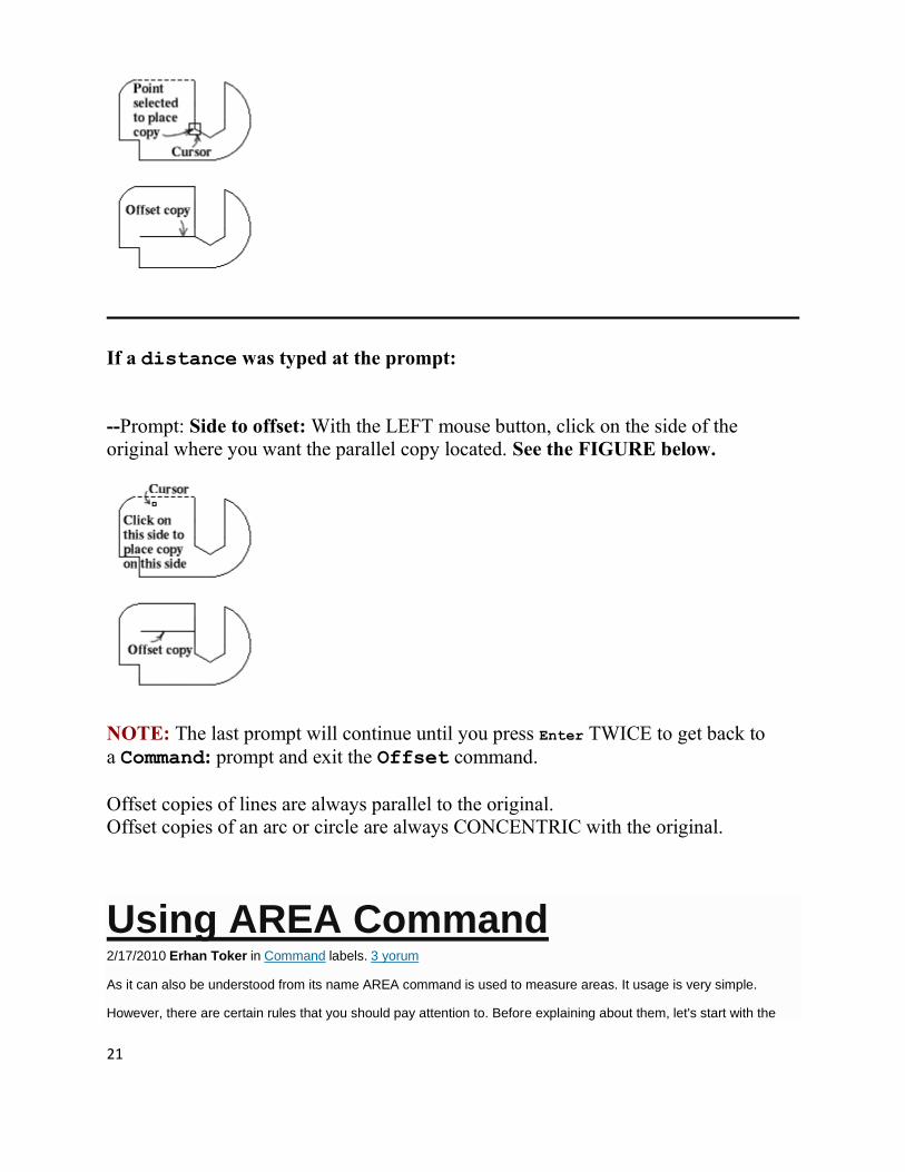
Fig.1
Let's try to measure the area that is shown in Fig. 1. It is very easy to access the command. All you have to do is to
write ‘AREA’ into the command line.
Command : _AREA
Specify first corner point or [Object/Add/Subtract]: ( 1 )
Specify next corner point or press ENTER for total: ( 2 )
Specify next corner point or press ENTER for total: ( 3 )
Specify next corner point or press ENTER for total: ( 4 )
Specify next corner point or press ENTER for total: ( ENTER )
Area = 84360.0000, Perimeter = 1162.0000
Areas are defined by using the corner points that make them up. The result is displayed by the same unit that you
assumed while creating the drawing. In the example drawing, this unit is accepted as cm. As a result, the measured
area will be given as cm² . The final point that you select does not have to be the first one that was selected.
AutoCAD assumes that the first and the last point that you select are joined. As a result, you obtain both area and

23
perimeter.
Now, let's examine the other options of the command. As you may have noticed, when you first enter the command,
you will get [Object/Add/Subtract] options. By using Object option, AutoCAD prompts you to select the entities that
may create areas. You can select a polyline that has at least three corners (vertex) or any other closed entities. If the
selection is not appropriate then AutoCAD will prompt you the error message ‘Selected object does not have an area’
. Add/Subtract options make the command in a continuous way and it permits you to select as many areas as you
want until you finish the execution of command. The area that you select is either added to the total area or
subtracted from it.
\
3D Modeling in AutoCAD- Solids
What is a Primitive Solid?
A primitive solid is a ‘building block' that you can use to work with in 3D. Rather than extruding or revolving an object, AutoCAD has some basic 3D shape commands at your disposal. From these basic primitives, you can start building your 3D models. In many cases, you get the same result from drawing circles and rectangles and then extruding them, but doing it one command is generally faster. Using these

24
with Boolean operations can be a very effective way of drawing in 3D. There are eight different primitives that you can choose from and are on the Home > Modeling Tool Panel (when in the 3D workspace).
The EXTRUDE command allows you to create a solid object from circles,
polygons, and objects, created from or converted to Polylines, that have "closed"
paths.
To access the Extrude command you can:
type extrude or ext at a Command: prompt
OR
select Solids, and then Extrude, under the Draw Menu.
—Prompt: Current wire frame density: ISOLINES=4
Select objects: Click on the object you wish to extrude and press Enter.
—Prompt: Specify height of extrusion or [Path]: Type in value and press Enter
(Click on the ICON below to go to the command)
SHAPE COMMAND ICON DESCRIPTION
BOX BOX
Creates a solid box after you provide 2 opposite corners and a height.
SPHERE SPHERE
Creates a solid sphere from a center point and radius.
CYLINDER CYLINDER
Creates a straight cylinder from a center point, radius and height.
CONE CONE
Creates a tapered cone from a center point, radius and height.
WEDGE WEDGE
Creates a triangular wedge from 2 opposite points.
TORUS TORUS
Creates a torus (donut shape) based on center point, radius and tube radius.

25
PYRAMID
PYRAMID /
PYR
Draws a solid object with a polygon (3-32 sides) base that rises to a central point.
POLYSOLID PSOLID
Draws a solid object with width and height as you would draw a polyline.
You can use primitives to either begin building a model, or it can even be a finished object on its own. Many of these commands are similar to 2D commands, except with an extra coordinate in the Z axis. Here is a summary of working with these commands.
BOX
Think of a box as an extruded rectangle. It has width, height and depth. It is created by establishing a starting corner and then establishing a second corner by either picking or giving relative coordinates.
Here is an example of this:
Command: box
Specify corner of box or [Center]: 2,3,4
Specify corner or [Cube/Length]: @5,7,10
This draws a box that is 5 units in the X-axis wide, 7 units long in the Y-axis and has a depth of 10 units in the positive Z-axis with one corner located at 2,3,4.
Here is another way of drawing that same box:

26
Command: BOX
Specify corner of box or [Center]: 2,3,4
Specify corner or [Cube/Length]: @5,7
Specify height: 10
Using this method, you establish the first corner as before, but only enter the X and Y coordinates of the opposite corner. AutoCAD will then prompt for the height.
Another way of drawing a box is to establish where the center of the box will be:
Command: BOX
Specify corner of box or [CEnter] <0,0,0>: C
Center of box <0,0,0>: <ENTER> or <PICK A POINT>
Specify corner or [Cube/Length]: @2,3,4
This draws a box that is 4x6x8 based about the center of 0,0,0.
If you want to draw a perfect cube, you can use this option:
Command: BOX
Specify corner of box or [CEnter]<0,0,0>: <pick point>
Specify corner or [Cube/Length]: C
Length: 4
This draws a cube with all sides equal to 4 units based of off a picked point.
The last way of drawing a cube allows you to enter the Length, Width and Height as separate distances, and not based on coordinate points.
Command: BOX
Center/<Corner of box> <0,0,0>:
Cube/Length/<other corner>: L
Length: 5 <X AXIS>
Width: 4 <Y AXIS>
Height: 6 <Y AXIS>
Of course you can also draw a box by picking two opposite corners with your mouse. This is useful for filling in areas and can be very quick. Make sure to use your Osnaps.
AutoCAD 3D and AutoCAD Map are AutoDesk’s software that has capabilities for analyzing 3
dimensional data like LIDAR point cloud data (x, y, z data). AutoCAD® Map 3D GIS mapping software offers
easier access to design, GIS, imagery, point cloud, and business information from a broad range of sources,
including Esri, Bentley, Oracle, GE, and other software providers. By using comprehensive data models for the gas,
water, wastewater, and electric industries, you can organize disparate asset information and apply industry
standards and business requirements to your data.

27
CAD STANDARDS
The essence of standards is to promote improvement of the quality of products, services and sound
management practices in the geospatial industry. CAD drawings need to conform with industry standards so as
to improve on sharing and appreciable understanding of the meaning of a drawing. The following is an extract
from the City of Everitt Survey and CAD standards. The standards describe vertical applications, layer names
and color standards, linetypes and standard symbols that can be used in survey drawings. The CAD for a city
or country is usually an elaborate document detailing every feature and its representation in terms of the
geography and map symbology for both text and other graphics.
Abbreviation Description
CULV Culvert
CYL Cylinder
D
D Depth, Dipole
DB Direct Burial Cable
D/L Daylight
D/W Driveway
DBL Double
DCL Ditch CL
DE DE-Energize
DEG Degree
DET Detail or Detector
DI Ductile Iron DIA Diameter

28
E
E East, Electrical
EA Each
ECb Buried Electrical Cable
ECC Eccentric
EF Each Face
EJB Electric Junction Box
EL Easement Line, Elevation
ELB Elbow
ELEC Electrical
ELEV Elevation
EMB Embankment
EMH Electrical Manhole
ENCL Enclose
ENG Engine
ENGR Engineer
EO Edge of
EOA Edge of Asphalt
EOC Edge of Concrete
EOD Edge of Dirt
EOG Edge of Gravel
EP Edge of Pavement
EQ Equal
EQUIP Equipment
ET Everett Transit
EV Electrical Vault
EVC End Vertical Curve
EVP Emergency Vehicle Pre-Emption
EVT Everett, City of
EW Each Way
EX Existing, Example
EXC Excavation
EXIST Existing
EXP Expansion
EXP JT Expansion Joint
EXT Exterior, Extension, Extruded
F
F Flanged

29
-

30
Screen clipping taken: 11/27/2012, 11:52 AM