Embed Size (px)
Citation preview
Computer Aided Assembly Animation of a Tricycle for Paraplegics
S.P. Ayodeji, and M.K . Adeyeri
ABSTRACT- This paper explicitly report on computer aided assembly animation of a tricycle for paraplegics who have difficulty in the use of lower limbs for mobility or driving.The development started with studying of existing tricycle and a case study of the recommended design standard for the features of vehicular cabs was taken. Analysis of the design requirements was made to determine all that would be required for the development. Draft was developed and transformed into a more precise design with results from anthropometric data taken into consideration by the use of high level languages such as AutoCad/Rivet, 3D Studio max, Adope Premiere pro, Adope flash, Adope dream weaver, Adope fireworks and photoshop. The tricycle comprises body layout, front and rear longitudinal members, main floor unit, engine position, wheel base, luggage space, the rear seat panel, boot floor, rear bumper, electrical and lighting system, chassis, ignition system, handle bar, fuel tank, brake and gear selector, adjustable seat, engine access booth, two side mirrors, back and front tyres, exhaust pipe and adjustable seat engine. Through the collection of design data and well defined textural representations of parts of the tricycle, it can easily be produced locally for paraplegics.
Key words: assembly and animation, computer aided, paraplegics,tricycle
I. INTRODUCTION
Paralysis is loss of voluntary movement in a part of the human body, caused by disease or injury anywhere along the motor-nerve path from the brain to the muscle fiber. Paralysis may result from injury, poisoning, infection. Incomplete paralysis, called paresis, is often caused by infections, trauma, or poisons that temporarily suppress motor activity but do not extensively damage nerve cells. paralysis of both lower limbs as paraplegia; Paralysis of one limb is known as monoplegia; paralysis of two limbs on the same side of the body is known as hemiplegia; and paralysis of all four limbs as quadriplegia or tetraplegia limitations often experienced by this category of people even with the available mechanical facilities most especially for mobility, can still be reduced considerably. Tricycles have a great alternative for people with balance problems or some form of disability preventing them from riding a standard bicycle. And this has indeed served as motivation for researching into this computerised assembly animation work.
Manuscript recieved on 22nd March, 2011 and revised till 5th April 2011 S.P. Ayodeji and M.K. Adeyeri both lecture in the department of Mechanical Engineering, at the Federal University of Technology, Akure, Ondo State, Nigeria with the following respective e-mail addresses: [email protected] ; [email protected]
II. LITERATURE REVIEW
Early tricycles were mostly for adults. Adult pedal tricycles are known to have been existing since 1868 [1]. The evolution of tricycles began along side with its wheel-chair counterpart [6]. Before the 20th century, the use of wheel chair was interpreted as the facture of medicine to find a cure to paraplegic problems. Tricycle advances from pedal tricycle to rustler tricycles, rustler led to the spider tricycle pedicab which is a unique design of recumbent pedicab. It is a front wheel driven tricycle that is articulated behind the driver seat [5]. The motorised tricycle was developed, which is a mechanical system used by paraplegic patient to aid their mobility. It is powered by an engine and it may either be in delta or tadpole configuration [4]. Simulation is defined as the numeical techniques for conducting experiment on a digital computer which involves certain types of mathematical and logical relationships neccessary to describe the behaviour and structure of complex real world system over extended period of time[3].
Traditionally, formal modeling (spelled 'modelling' in British English) of systems has been via a mathematical model, which attempts to find analytical solutions to problems and thereby enable the prediction of the behavior of the system from a set of parameters and initial conditions[2]. While computer simulations might use some algorithms from purely mathematical models, computers can combine simulations with reality or actual events, such as generating input responses, to simulate test subjects who are no longer present. Many research works had been done on tricycles, computer aided design of various engineering structures and assembly. But the present work is basically considering the working class of paraplegics based on the 5th percentile female and 95th percentile male anthropometric data which is a new area yet to be covered. And the unique specialty of the work is the integration of computer aided design, modeling and simulation through the use of relevant computer programs to aid the assembly procedure of Tricycle for the paraplegics. This will help the accuracy, save time and make it flexible thereby improving quality and efficiency of the assembly procedure.
III. METHODOLOGY
Basically, the designing process was carried out using AutoCAD in conjuction with 3D studio max, The animation and rendering was carried out using 3D Max and Adobe Premiere, the still images is edited with adobe photoshop in conjuction with Adobe fireworks, the text animation is done
Proceedings of the World Congress on Engineering 2011 Vol II WCE 2011, July 6 - 8, 2011, London, U.K.
ISBN: 978-988-19251-4-5 ISSN: 2078-0958 (Print); ISSN: 2078-0966 (Online)
WCE 2011
with Adobe flash and the linking of the videos is done with Adobe Dreamweaver which is the final phase of the project.
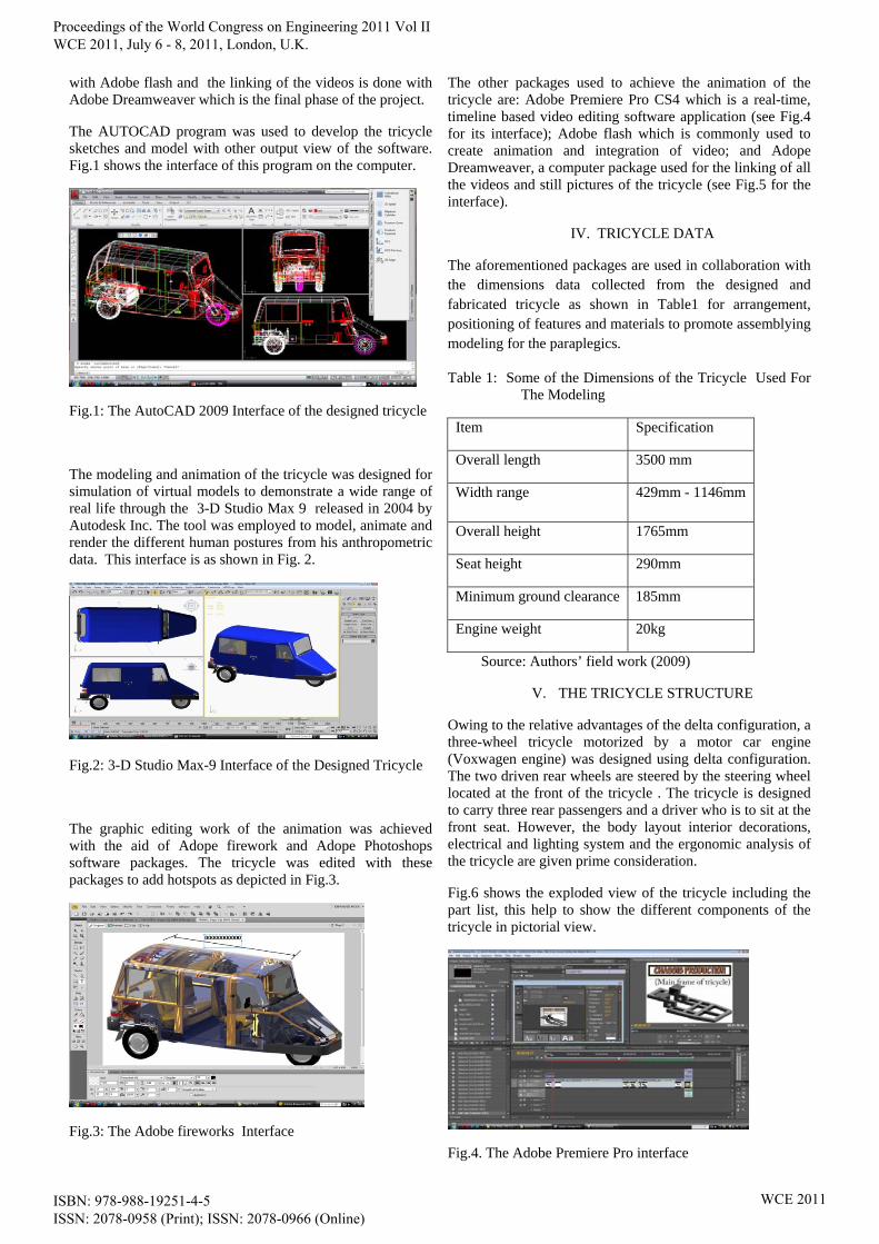
The AUTOCAD program was used to develop the tricycle sketches and model with other output view of the software. Fig.1 shows the interface of this program on the computer.
Fig.1: The AutoCAD 2009 Interface of the designed tricycle
The modeling and animation of the tricycle was designed for simulation of virtual models to demonstrate a wide range of real life through the 3-D Studio Max 9 released in 2004 by Autodesk Inc. The tool was employed to model, animate and render the different human postures from his anthropometric data. This interface is as shown in Fig. 2.
Fig.2: 3-D Studio Max-9 Interface of the Designed Tricycle
The graphic editing work of the animation was achieved with the aid of Adope firework and Adope Photoshops software packages. The tricycle was edited with these packages to add hotspots as depicted in Fig.3.
Fig.3: The Adobe fireworks Interface
The other packages used to achieve the animation of the tricycle are: Adobe Premiere Pro CS4 which is a real-time, timeline based video editing software application (see Fig.4 for its interface); Adobe flash which is commonly used to create animation and integration of video; and Adope Dreamweaver, a computer package used for the linking of all the videos and still pictures of the tricycle (see Fig.5 for the interface).
IV. TRICYCLE DATA
The aforementioned packages are used in collaboration with the dimensions data collected from the designed and fabricated tricycle as shown in Table1 for arrangement, positioning of features and materials to promote assemblying modeling for the paraplegics.
Table 1: Some of the Dimensions of the Tricycle Used For The Modeling
Item Specification
Overall length 3500 mm
Width range 429mm - 1146mm
Overall height 1765mm
Seat height 290mm
Minimum ground clearance 185mm
Engine weight 20kg
Source: Authors’ field work (2009)
V. THE TRICYCLE STRUCTURE
Owing to the relative advantages of the delta configuration, a three-wheel tricycle motorized by a motor car engine (Voxwagen engine) was designed using delta configuration. The two driven rear wheels are steered by the steering wheel located at the front of the tricycle . The tricycle is designed to carry three rear passengers and a driver who is to sit at the front seat. However, the body layout interior decorations, electrical and lighting system and the ergonomic analysis of the tricycle are given prime consideration.
Fig.6 shows the exploded view of the tricycle including the part list, this help to show the different components of the tricycle in pictorial view.
Fig.4. The Adobe Premiere Pro interface
Proceedings of the World Congress on Engineering 2011 Vol II WCE 2011, July 6 - 8, 2011, London, U.K.
ISBN: 978-988-19251-4-5 ISSN: 2078-0958 (Print); ISSN: 2078-0966 (Online)
WCE 2011

Fig.5. The Dream Weaver Interface
Fig.6: The Exploded View of the Tricycle
Body layout
Two forms of vehicle body and chassis layout are commonly used;Integral (mono or unity) construction where the main aim is to strengthen necessary weight, and the construction does not employ a separated chassis frame for attachments of suspension, engine and other chassis and transmission components and The composite construction (conventional separate chassis). Here, the chassis and body are built as two separate units. The body is then assembled in to the chassis with mounting bracket, with rubber-bushed bolts to hold the body to the rigid chassis. The conventional construction method was used in the tricycle development (Fig.7 )
Fig 7: The Body Frame
Front and Rear Longitudinal Members
The front beam assembly houses the steering components such as the two handle steering rod, the dash board, fuel tank, the clutch pedal, the brake pedal and so on. It is designed to strengthen the front end; it is part of the crumble zone, giving lateral strength on impact and absorbing energy by deformation during a collision. The rear longitudinal members are design to support some of the engine weight, the passengers’ weights, and little luggage kept in the boot compartment.
Main Floor Unit
This unit commences at the front and spreads out symmetrically on both sides of the body, making the rear region wider than the front region.
Luggage Space
Unlike the conventional tricycle with luggage space above the engine compartment, the designed cycle has its luggage space at the rear of the tricycle. This space is free from the heat of the engine, making luggage kept save from heat.
The Rear Seat Panel
This is designed to carry three passengers. The seat panel is reinforced to gain enough strength to support the rear passengers. The front edge of the rear seat panel is stiffened by the rear seat wheel board, and the rear squab panel which completes this unit. It seals off the boot compartment from the passenger compartment.
Wheel Base
The wheelbase is a very important parameter to fix in designing a vehicle. The aim of the designer is to keep the wheelbase as short as possible consistent with the comfort required for the passengers.
Engine Position
The engine produces an effect from a given input. The engine is mounted on the engine sitting located at the back of the passengers’ seat
The designed tricycle engine is located somewhere at the center of the main floor of the vehicle. It is located partly beneath the passengers’ seat. It is located below the main floor of the tricycle so that air beneath can cool it during motion and more so to keep the heat generated from it from the passengers’ compartment, a rectangular shaped compartment was designed for the engine compartment (Fig. 8).
Proceedings of the World Congress on Engineering 2011 Vol II WCE 2011, July 6 - 8, 2011, London, U.K.
ISBN: 978-988-19251-4-5 ISSN: 2078-0958 (Print); ISSN: 2078-0966 (Online)
WCE 2011
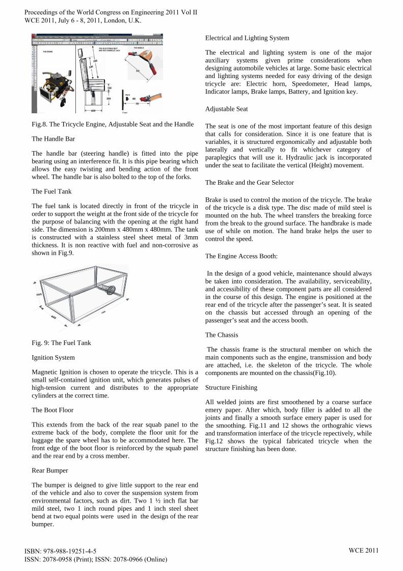
Fig.8. The Tricycle Engine, Adjustable Seat and the Handle
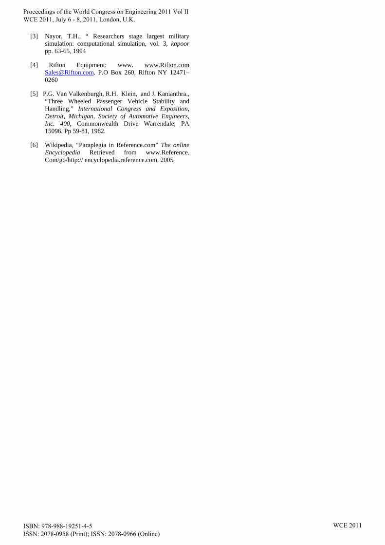
The Handle Bar
The handle bar (steering handle) is fitted into the pipe bearing using an interference fit. It is this pipe bearing which allows the easy twisting and bending action of the front wheel. The handle bar is also bolted to the top of the forks.
The Fuel Tank
The fuel tank is located directly in front of the tricycle in order to support the weight at the front side of the tricycle for the purpose of balancing with the opening at the right hand side. The dimension is 200mm x 480mm x 480mm. The tank is constructed with a stainless steel sheet metal of 3mm thickness. It is non reactive with fuel and non-corrosive as shown in Fig.9.
Fig. 9: The Fuel Tank
Ignition System
Magnetic Ignition is chosen to operate the tricycle. This is a small self-contained ignition unit, which generates pulses of high-tension current and distributes to the appropriate cylinders at the correct time.
The Boot Floor
This extends from the back of the rear squab panel to the extreme back of the body, complete the floor unit for the luggage the spare wheel has to be accommodated here. The front edge of the boot floor is reinforced by the squab panel and the rear end by a cross member.
Rear Bumper
The bumper is deigned to give little support to the rear end of the vehicle and also to cover the suspension system from environmental factors, such as dirt. Two 1 ½ inch flat bar mild steel, two 1 inch round pipes and 1 inch steel sheet bend at two equal points were used in the design of the rear bumper.
Electrical and Lighting System
The electrical and lighting system is one of the major auxiliary systems given prime considerations when designing automobile vehicles at large. Some basic electrical and lighting systems needed for easy driving of the design tricycle are: Electric horn, Speedometer, Head lamps, Indicator lamps, Brake lamps, Battery, and Ignition key.
Adjustable Seat
The seat is one of the most important feature of this design that calls for consideration. Since it is one feature that is variables, it is structured ergonomically and adjustable both laterally and vertically to fit whichever category of paraplegics that will use it. Hydraulic jack is incorporated under the seat to facilitate the vertical (Height) movement.
The Brake and the Gear Selector
Brake is used to control the motion of the tricycle. The brake of the tricycle is a disk type. The disc made of mild steel is mounted on the hub. The wheel transfers the breaking force from the break to the ground surface. The handbrake is made use of while on motion. The hand brake helps the user to control the speed.
The Engine Access Booth:
In the design of a good vehicle, maintenance should always be taken into consideration. The availability, serviceability, and accessibility of these component parts are all considered in the course of this design. The engine is positioned at the rear end of the tricycle after the passenger’s seat. It is seated on the chassis but accessed through an opening of the passenger’s seat and the access booth.
The Chassis
The chassis frame is the structural member on which the main components such as the engine, transmission and body are attached, i.e. the skeleton of the tricycle. The whole components are mounted on the chassis(Fig.10).
Structure Finishing
All welded joints are first smoothened by a coarse surface emery paper. After which, body filler is added to all the joints and finally a smooth surface emery paper is used for the smoothing. Fig.11 and 12 shows the orthograhic views and transformation interface of the tricycle repectively, while Fig.12 shows the typical fabricated tricycle when the structure finishing has been done.
Proceedings of the World Congress on Engineering 2011 Vol II WCE 2011, July 6 - 8, 2011, London, U.K.
ISBN: 978-988-19251-4-5 ISSN: 2078-0958 (Print); ISSN: 2078-0966 (Online)
WCE 2011

Fig.10. The Chassis and body frame of tricycle
Fig.11. orthographic view
Fig.12: Transformation interface of the designed tricycle
Fig. 13: The 3-D Tricycle
VI. THE ASSEMBLY SIMULATION OF TRICYCLE
The Assembly Video software was designed to run on most system even low capacity ones. However, for optimum performance, a minimum configuration of Pentium-1, 233- MHz is required with a minimum of 10Gb free space on the hard disk installed and 512RAM or higher.
The Video software stored on CD-R upon insertion into a machine will auto run itself on any Windows operating system without the user having to run it. However if it does not auto run, user have the option of running the software by clicking on My Computer directory and copy all the folder file from the CD/DVD drive and paste it to the hard disk space , On completion, the CD should then be removed from the computer.
Then install the browser called opera in the folder package, after this, right click on Assembly Simulation Videos and click on open with opera, this starts the video software automatically. Clicking on any various buttons on the browser interface will show the prepared video of the tricycle as depicted in Fig.14
Fig.14.: The Introductory Display of the Video Software Interface
VII. CONCLUSION
This work shows simulated modeling stages of a tricycle for paraplegics using the various computer programs mentioned earlier,the final output of the project is in form of videos showing different parts and dimensions of the tricycle and this can be shown by clicking each component buttons in any browser applications.
Through the collection of design data and well defined textural representations of parts of the tricycle, it can easily be produced locally for paraplegics.
This work is a major breakthrough for the model user and model builder in terms of graphical representation of the tricycle process production.
REFERENCES
[1] Jeifrey and Brian, first recorded usage of tricycles and as an example 2001
[2] Karl, P. and Marx, S. “The World as a Process, Simulations in the Natural and as an example”, Kluwer, pp. 77-100., 1990
Proceedings of the World Congress on Engineering 2011 Vol II WCE 2011, July 6 - 8, 2011, London, U.K.
ISBN: 978-988-19251-4-5 ISSN: 2078-0958 (Print); ISSN: 2078-0966 (Online)
WCE 2011
[3] Nayor, T.H., “ Researchers stage largest military simulation: computational simulation, vol. 3, kapoor pp. 63-65, 1994
[4] Rifton Equipment: www. www.Rifton.com [email protected]. P.O Box 260, Rifton NY 12471–0260
[5] P.G. Van Valkenburgh, R.H. Klein, and J. Kanianthra., “Three Wheeled Passenger Vehicle Stability and Handling,” International Congress and Exposition, Detroit, Michigan, Society of Automotive Engineers, Inc. 400, Commonwealth Drive Warrendale, PA 15096. Pp 59-81, 1982.
[6] Wikipedia, “Paraplegia in Reference.com” The online Encyclopedia Retrieved from www.Reference. Com/go/http:// encyclopedia.reference.com, 2005.
Proceedings of the World Congress on Engineering 2011 Vol II WCE 2011, July 6 - 8, 2011, London, U.K.
ISBN: 978-988-19251-4-5 ISSN: 2078-0958 (Print); ISSN: 2078-0966 (Online)
WCE 2011