Embed Size (px)
Citation preview

COMPUTATIONAlL HYDRAUlLICS FOR
CIVIlL ENGINEERS

COMPUTATIONAL HYDRAULICS FOR
CIVIL ENGINEERS
THEODORE V. HROMADKA II, PH.D., PH.D .. R.C.E. Research Associate
Princeton University Princeton. New Jersey
BARRY L. BEECH, R.C.E. Hydraulics Engineer
Williamson & Schmid Irvine. California
JAMES M. CLEMENTS Systems Anolyst
Williamson & Schmid Irvine, CaiJlornia
Lighthouse Publications
J\.Ii<!;ion Viejo. California
Copyright [986
Library of Congress caralog number 86-081847
First Lighthouse Publinrouns edition
ISBl'i 0-914055-04-6
This Work is subject to copyrigtu. All rights an reserved. wherherrhe whole or paM of tht material is concerned. spt"cificaJly those of U"oa.nsl.uiOll, reprintin8. re·use of illustrations, broadcasting, reproclucrion by pno(ocopying machine or 'imilar means, and siorage: in da1a bank.s. The Lue of register~ names. trad~mjlrks. eu:. in t.his publication does not )mpJy, even in tht' "bsenu of a specirtc statement,rhat such namel are exempt from the ~Ievant prOlecri..,r- laws and regulations and thrrrfolT f~ for general use.
NOTICE
No patent liabihty is. assumed with respect tD the use of the information contained herein. While every
preca.1J,.(\on nf.l% been Oiken fet the ("«,,,MattOn of this book. the publisher assumes no responsibility for errors
or omissions. Seither is any liability assumed for damages resulting from the Use [)f the information tontaint:'d hp.re.in_
vi
ACKNOWLEDGEMENTS
A special debt of gratitude is due Advanced Engineering Software, for permitting the problem solving portion of their computer code to be published herein. James M. Clements, M.s. is especially acknowledged for his contribution of much of the code and text found in Chapter 3. Acknowledgements are also paid to William V. Burchard and Linda Laurenzi for their fine graphic skills. Portions of ·Computer Methods in Urban Watershed Hydraulics· (Lighthouse Publications, 1984) have also been referred to in this text.
viii
PREFACE
This book has evolved from the documentation for a specialized water resources program package IMlIWJLICS ELEMENl'S I developed by Advanced Engineering Software (AES), Irvine, California. 'Ihe program package has been marketed throughout the world since 1981 and has gained a widespread audience of program users including practicing civil engineers, City, County and state officials, students, and university faOllty. Besides providing an extensive library of open channel flow hydraulics problem-solving software, the AES program package is an excellent example of the state-of-the-art in user-friendly or "humanized" software. '!bat is, there is no real need for program documentation: the program .ia. the documentation. All data entry, parameter selection, and program editing features are internal of the program.
'1hl.s book presents the basic theory which is fundamental to cpen channel flow hydraulics and then presents the guidelines used by AES in their developmental procedures for a "humanized" software product. Software code (batch mode) is included which provides the powerful library for solving open channel flow hydraulics problems. Finally, several examples are provided to

illustrate many of the features and capabilities of the provided codes.
Should the reader elect to key in the provided software codes and operate the programs in the batch mode, a time allocation of approximately forty hours should be planned in order to enter the programs, provide the machine-dependent file manipulation coding (e.g. I file open and close statements), "debugging" the programs, and verification of the programs using the many example problems provided in Chapter 5. Another option is to purchase the AES humanized software package directly. The necessary licensing agreement and order information is provided following the book references.
xi

CONTENTS
Preface ix 1. 'lO~~ 1
1.1 .I\boo.t the IlOdt 1 1.1.1. Included Software Codes 1 1.1.2. Review of Open Channel Flow Hydraulics 3 1.1.3. Included Application Problems 3 1.1.4. nUser-Friendly" Guidelines 3 1.1.5. COmputer Code Preliminaries 4
1.2. Developing User-Friendly <:aJputer Software .. 1.3. Data Entry strategies 6
1.3.1. Requirements for Interactive Software 8 1.3.2. Screen Layout Strategy 9
1.4. Flow of User Data 10 1.5. SCreen Design Method 11 1.6. SUbroutine Descriptions 12
1.6.1. SUBRXlTINE CRINIT 12 1.6.2. SUBRXlTINE CUROOR 12 1.6.3. SUBroUTINE GE'l'VAL 13 1.6 .4. SllBrolJI'INE NUM:K 14 1. 6 .5. SllBOOIJI'INE ERROR 15 1.6.6. SUBOOUTINE CLEAN 15 1.6 .7. SllBOOtn'INE BELL 16 1.6.8. SUBROUl'INE CLRSCR 16 1.6. 9. SllBOOIJI'INE INFO 16 1.6 .10. SUBROOTIt£ ALJ:[JW 17
2. C£A<JSIFlCATIONS Cf' <PEN awH:L FIDW FtBlIIMJlN.rAIB 2.1. Definitions 2.2. Manning's Elpatian 2.3. Froude limber 2.4. <:arp.tter PrograDB
xiii
26 26 27 28 28
3. CPER awu:r. FUM 29 3.1. IntroWction 29 3.2. Conservation of Mass, MouelilUm, and Energy 29
3.2.1. Conservation of Mass 29 3.2.2. Conservation of Monmtum 30 3 .2.3. Conservation of Energy 31
3.3. Fundamentals of Hydraulics 33 3.3.1. Hydraulic Grade Line and Energy Grade Line 33 3.3.2. Specific Energy 33 3.3.3. The specific Force 35 3.3.4. Hydraulic Jump in a Rectangular Channel 37
3.4. Gradnally varied Flow 37 3.4.1. S Profiles 38 3.4.2. M Profiles 38 3.4.3. C Profiles 40 3.4.4. Standard Step Method 40
4. IMIWlLIC I!UItml'S 43 4.1. Introduction 43 4.2. PKXlWIl. Hydraulic Elements Main Menu 45 4.3. PKXlWI 2. Cllannel Hydraulic Elements 45 4.4. PKlGWt 3. Pipeflow Hydraulic Elements 45 4.5. PKJGWI 4. streetflow Hydraulic Elements 45 4.6. PKXlWI 5. Pipeflow Jlmction JInalysis 46 4.7. PKJGWI 6. Grad!!a)]y varied Plow in Open Olannels 47 4.B. PKXlWI 7. Gradually varied Plow in Pipelines 47
5. HmRl\DLIC EL1lMENl'S EXAMPLE PIOWH3 90
~ 131
sa;"1WARE PIJlUII\SE ~ 132
xiv
1.1. About the Book
CHAPTER ONE
INTRODUCTION TO
USER-FRIENDLY SOFTWARE
With the recent advances in microcomputer capabilites, the use of computer software to solve problems in water resources engineering has increased severalfold. The potential benefits available in the use of computers to solve water resources problems is especially fruitful in the specialized field of open channel flow hydraulics.
The design of land development projects, flood control systems, and water supply or irrigation systems all involve a significant computational effort in the sizing and evaluation of structures to carry the flow of water. Therefore, the use of computer software to solve the most frequently occurring problems will reduce design time expenditure costs. and possibly project construction costs due to a more finely tuned design product.
1.1.1. Included Software Codes
Presented in this book are several FORTRAN computer programs for solving open channel flow hydraulics problems involving steady
2
INTRODUCTION TO USER-FRIENDLY SOFTWARE
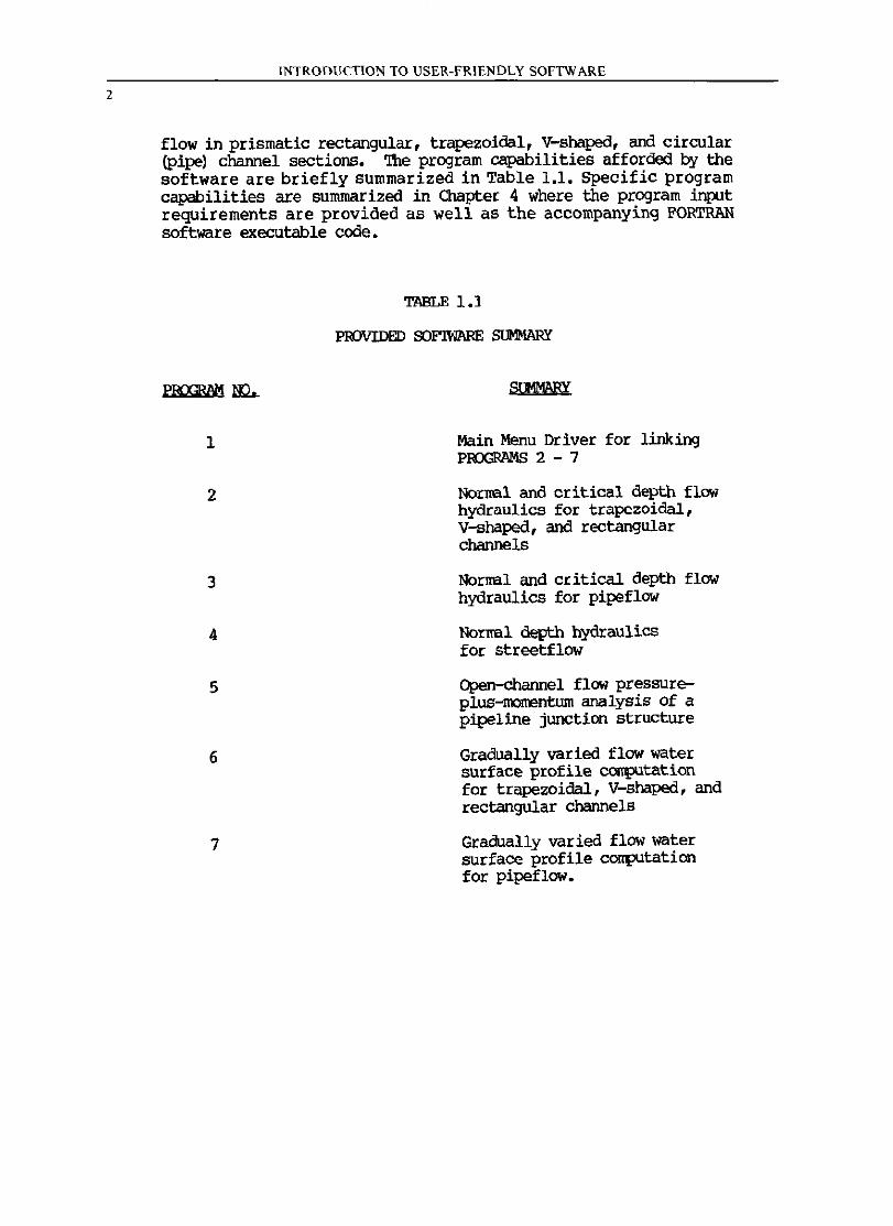
flow in prismatic rectangular, trapezoidal, V-shaped, and circular (Pipe) channel sections. '!he program capabilities afforded by the software are briefly summarized in Table 1.1. Specific program capabilities are summarized in Chapter 4 where the program input requirements are provided as well as the accompanying FORTRAN software executable code.
1
2
3
4
5
6
7
TABLE 1.1
PROVIDED SOFlWARE SUMMARY
Main Menu Driver for linking POOGRl-IMS 2 - 7
Normal and critical depth flow hydraulics for trapezoidal, V-shaped, and rectangular channels
Normal and critical depth flow hydraulics for pipeflow
Normal depth hydraulics for streetflow
Open-channel flow pressureplUS-IOOrrentum analysis of a pipeline junction structure
Gradually varied flow water surface profile computation for trapezoidal, V-shaped, and rectangular channels
Gradually varied flow water surface profile computation for pipeflow.
INTRODUCTION TO USER-FRIENDLY SOFTWARE
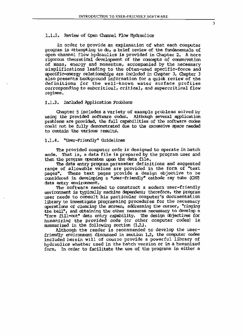
1.1.2. Review of Open Channel Flow Hydraulics
In order to provide an explanation of what each computer program is attempting to do, a brief review of the fundamentals of open channel flow hydraulics is provided in Chapter 2. A more rigorous theoretical development of the concepts of conservation of mass, energy and momentum, accompanied by the necessary simplifications leading to the often-used specific-force and specific-energy relationships are included in Chapter 3. Chapter 3 also presents background information for a quick review of the definitions for the well-known water surface profiles corresponding to subcritical, critical, and supercritical flow regimes.
1.1.3. Included Application Problems
Chapter 5 includes a variety of example problems solved by using the provided software codes. Although several application problems are provided, the full capabilities of the software codes could not be fully demonstrated due to the excessive space needed to contain the various results.
1.1.4. "User-Friendly" Guidelines
The provided computer code is designed to operate in batch mode. That is, a data file is prepared by the program user and then the program operates upon the data file.
The data entry program parameter definitions and suggested range of allowable values are provided in the form of "text pages". These text pages provide a deSign objective to be considered in developing a ·user-friendly" cathode ray tube (CRI') data entry environment.
The software needed to construct a modern user-friendly environment is typically machine dependent; therefore, the program user needs to consult his particular computer's documentation library to investigate programming procedures for the necessacy opecations of clearing the screen, addressing the cursor, "ringing the bell", and obtaining the other measures necessary to develop a "form fill-out" data entry capability. The design objectives for humanizing the provided code (or other computer codes) is summarized in the following section (1.2.).
Although the reader is recommended to develOp the userfriendly enVironment discussed in section 1.2, the computer codes included hecein will of course provide a powerful library of hydraulics whether used in the batch version or in a humanized form. In order to facilitate the use of the programs in either a
3
4
INTRODUCTION TO USER-FRIENDLY SOFTWARE
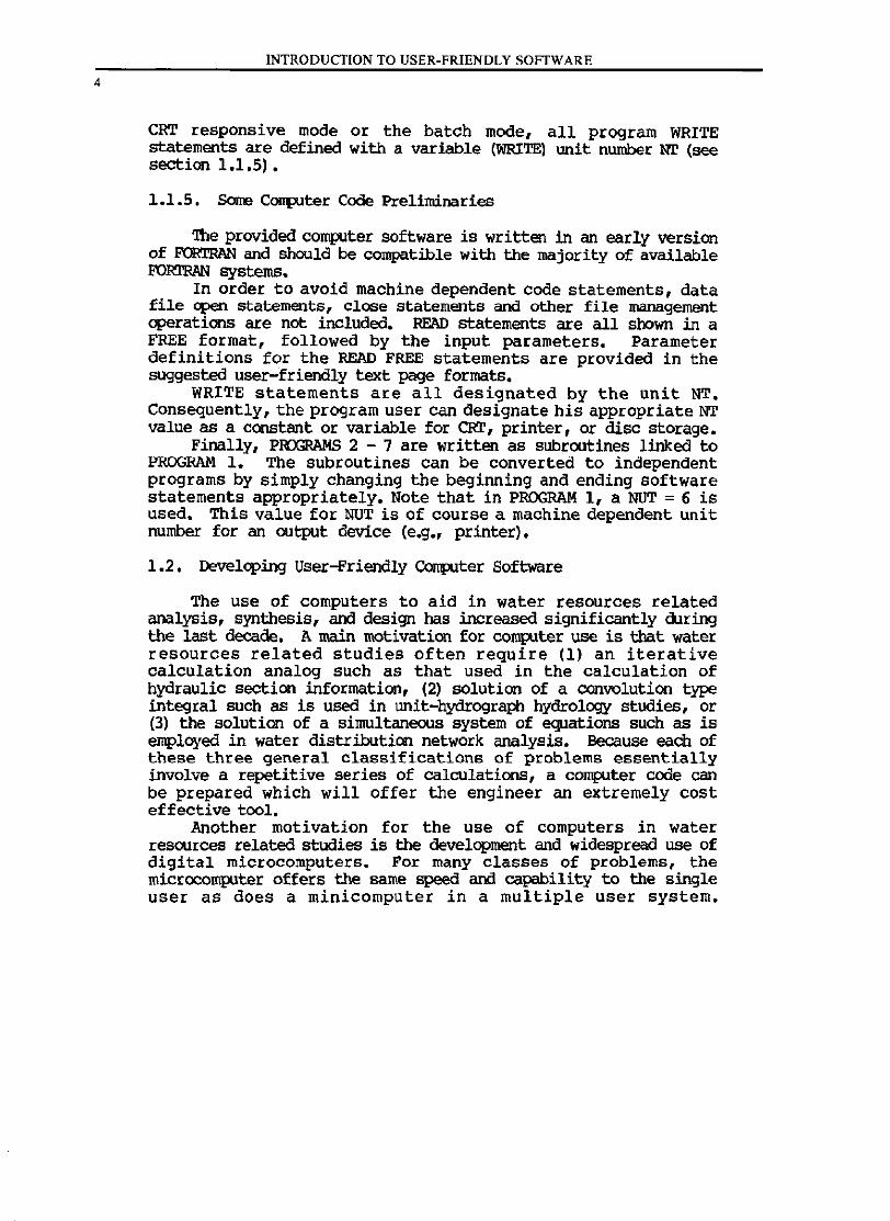
CRT responsive mode or the batch mode, all program WRITE statements are defined with a variable (WRITE) unit number Nr (see section 1.1.5) •
1.1.5. Some C<JIIIlUter Code Preliminaries
':the provided computer software is written in an early version of FORTRAN and should be compatible with the majority of available FORI'Rl\N systems.
In order to avoid machine dependent code statements, data file open statements, close statements and other file management operations are not included. READ statements are all shown in a FREE format, followed by the input parameters. Parameter definitions for the READ FREE statements are provided in the suggested user-friendly text page formats.
WRITE statements are all designated by the unit NT. Consequently, the program user can designate his appropriate NT value as a constant or variable for CRT, printer, or disc storage.
Finally, PROGRAMS 2 - 7 are written as subroutines linked to PROGRAM 1. The subroutines can be converted to independent programs by simply changing the beginning and ending software statements appropriately. Note that in PROGRAM 1, a NUT = 6 is used. This value for NUT is of course a machine dependent unit number for an output device (e.g., printer).
1.2. Developing user-Friendly ~ter Software
The use of computers to aid in water resources related analysis, synthesis, and design has increased significantly during the last decade. A main motivation for cornplter use is that water resources related studies often require (1) an iterative calculation analog such as that used in the calculation of hydraulic section information, (2) solution of a convolution type integral such as is used in unit-hydrograph hydrology studies, or (3) the solution of a simultaneous system of equations such as is employed in water distribution network analysis. Because each of these three general classifications of problems essentially involve a repetitive series of calculations, a computer code can be prepared which will offer the engineer an extremely cost effective tool.
Another motivation for the use of computers in water resources related studies is the development and widespread use of digital microcomputers. For many classes of problems, the microcomputer offers the same speed and capability to the single user as does a minicomputer in a multiple user system.
INTRODUCTION TO USER-FRIENDLY SOFTWARE
Consequently, programming teclmiques which were once limited to the minicomputer or the mainframe class of computers is now available at low cost by means of a microcomputer system.
Such programming techniques include 'humanized' computer interaction and detailed, easy to read computer results which are explicit, fit the requirements of a reviewing agency, and yet are understandable to the first-time reviewer of the product.
By making the program humanized, the learning curve is essentially minimized in that all program information is prompted and scanned for acceptability and can be rejected if data is not within program specified limits. In general, the user's manuals associated with a wide variety of batch programs are eliminated because the humanized program guides the user through every possible logic path, providing the user with various checks and controls in order to further reduce parameter selection errors and an unreasonable choice of design options.
The development of the humanized software may be defined as a uniform communication/ presentation (C/P) to the program user. There are several CjP requirements for computer software which are described as follows:
1. For a sequence of data entry prompts, the page number and calculation model description awears at the top of the page.
2. All words are written in their entirety, with abbreviations avoided whenever possible.
3. All units should be given for the information requested.
4. Allowable values are identified which limit the data entries to reasonable quantities.
5. Should there exist standardized criteria for parameter values, the recommendations are included on the display.
6. Any program operation commands should be consistently and uniformly displayed so that the user can operate the interaction or special data editing features without confusion.
7. A 'failsafe' line appears on the CRT screen for each page. This line is located near the bottom of the screen and appears in the same position on each page. Below the failsafe line occurs all program operating instructions. These instructions can be typed by the program user at any time and will cause the program to respond instantly.
5
6
INTRODUCTION TO USER-FRIENDLY SOFTWARE
8. All computer-dependent requirements (such as data file manipulation) for data management should be interior of the software so the program user need not be knowledgeable of computer operations in order to utilize the program.
9. The C/p should be uniform between software products. By requiring uniformity of software interaction, individual programmer personality traits can be avoided. The result is a library of software wherein each program O£l9rate5, interacts, and responds identically. Consequently, the user learning curve is minimized.
By using a program which provides an easy-to-read output product, the usual deSign review procedure is minimized which reduces total cost to both the design engineer and the design review team. Additionally, the computer product should be the actual fully prepared report which is to be submitted, containing the usual introductory pages, and the study results should be produced in the reviewing agency's required computer-printed forms or plotted graphs. The computer program then provides an actual engineering product, minimizing the need for secretarial and graphic efforts.
1.3. Data Entry Strategies
Typically, most water resources software uses a "batch moden
data entry where a data file is prepared using the computer's editor, and then the program executed. Due to data entry errors or errors in deSign judgement, this process is repeated several times until the final product is achieved. A more modern approach to data entry is by direct access to the program computations through cc:mrunication by means of the cathode ray tube (CRl').
The interactive display presented to the user on the terminal by the application program is usually of a type called scrolling. Scrolling is presenting a line of characters or text on the bottom of the terminal screen. This line moves upwards continually as new lines of information are added. This type of presentation differs from natural reading techniques such as reading a book in that the material moves upward instead of the eyes moving downward across a steady displaY.
When using the scroll technique for data entry, the program user is not aware of the next input requirements until it actually appears on the bottom of the screen. If errors occur while entering data, messages are displayed and scroll up while repeat prompts for user input are again requested by the program.
INTRODCCTION TO USER,rRlENDLY SOfTW ARE
Multiple occurrences of e~rors usually result in a screen full of scrolling error messages which often add to the confusion. Normally, scrolling interaction never allows a user to change a data entry once it is acceptea by the program unless the user restarts the prograrr. (thus losing all previously entered data) or edits the data if the capability exists within the prograrr .•
In contrast, humanized form-fill out display interaction closely simulates natural reading or viewing characteristics. Ml textual information or data entry requests are assembled in logically related groups to fit comfortably on text Pilges. These pages are presented to the user by clearing the eRr screen of all previous information before displaying the current page. '!be text information is displayed starting at the top of the screen and proceeds downward until the bottom limit of the screen is reached, enabling the user to observe a stable screen of related information. In the case of data entry, related requests for user input are displayed simultaneously, enabling the user to foresee subsequent data entry requests. The CRT cursor moves down the screen after each inplt request is satisfied. This cursor movement is the key to powerful screen interaction.
A typical terminal screen can be visualized as a matrix containing 24 lines by 80 columns or 1920 elements. One may individually address these elements by programmed movement of the cursor to the selected element. Textual sequences can be displayed anywhere on the screen at any time while retaining or erasing previOUS information. This allows warning signals or error messages to appear next to the data in question and disappear after the error has been corrected, thus leaving the original page of displayed information intact. Another powerful use of cursor movement is in the case of data entry on a page affecting the permiSSible values of subsequent data entries on the same page. The allowable values displayed under a subject data entry prompt can be cursor addressed, changed to new values, and the cursor returned to the previous selection instantly. This method employs full conversational awareness by the computer system at all times. Since the viewing displays are constructed in text pages, the user can manipulate the pages by a set of understandable interaction commands such as those listed in the following:
1. 'lOP: request to clear the screen, re-display the page and return the cursor to the first input request on the current page. This permits modification of data 00 the page.
2. BACK:returns to the previous page for corrections or changes.
7
8
INTRODUCTION TO USER-FRIENDLY SOFTWARE
3. MAIN: terminates the program function in progress, manipulates computer files as needed, and returns to the main program menu of available processes.
4. EXIT: terminates the program function in progress, closes all computer files as needed, and exits the program.
User directed page movements, coupled with the dynamic display qualities attained through programmed addressable cursor movements, provide a powerful and flexible interactive environment for expedenced as well as first time computer program users.
1.3.1. Requirements for Interactive COnpJter Software
An important consideration for selecting an interactive software strategy is compatibility among various computer hardware. Unfortunately, wide differences still exist between manufacturers of peripheral devices such as terminals and computer resident system programs called operating systems. !Jevelq;>ing an interactive design methodology that is dependent upon a particular type of hardware or the operating system of a certain computer generally promotes the eventual demise of the approach. The constant change of operating systems due to computer vendor upgrades may render the programming required to accomplish such a design incOllqlatible with the revised system.
More likely to occur is the typical change or upgrades of CRl' devices or terminals which may not accommodate some of the interactive features programmed for the previous device. The hardware or operating system dependent functions can be justified in the case where the application software and hardware are bundled together to form a functional package. These types of pad<ages normally deal with graphics awlications such as ClIDjCAM systems or elaborate word processing systems. 'lbe special purpose computers are mostly self-contained systems requiring certain hardware and operating system configurations.
An interactive design method has to merge comfortably with the major application systems that are already on the machine such as engineering, accounting information retrieval systems, and word processing. In order to accomplish this task and maintain compatability among a wide selection of terminals and operating systems, a certain sUbset or core group of interactive functions are developed which will perform all the major tasks of a humanized form-filled interactive method. The basic functions that are compatible with over 95% of the terminal hardware and computer systems available today are absolute cursor addressing, clearing the screen, and nringing the beU".
Another requirement is the ability of the computer system to send out what is called control characters which excite these
INTRODUCTION TO USER-FRIENDLY SOFTWARE
functions. Using these basic functions as building blocks, an entire sophisticated 'humanized' interactive approach can be accomplished while still retaining compatibility across vendor lines. Changes in terminal control character sequences for various terminals are accomplished by an easily accessible hardware table contained within the interactive application driver routines or by table files. These tables map the function to the device. There are many other functions available in terminals such as highlighting or dimming of certain groups of text, flashing of warning messages, and split screening for multiple tasks. These are not normally available in all terminals and are usually reserved for the higher priced models. In addition, the particular code sequences to start and stop these functions are widely different. These functions are just extensions of the basic three required to develop such a user friendly system. A well designed interactive system using the basic three functions of cursor addressing, clear screen, and bell satisfies fully the criteria required to produce a truly humanized interactive methodology •
1.3.2. Screen Layout Strategy
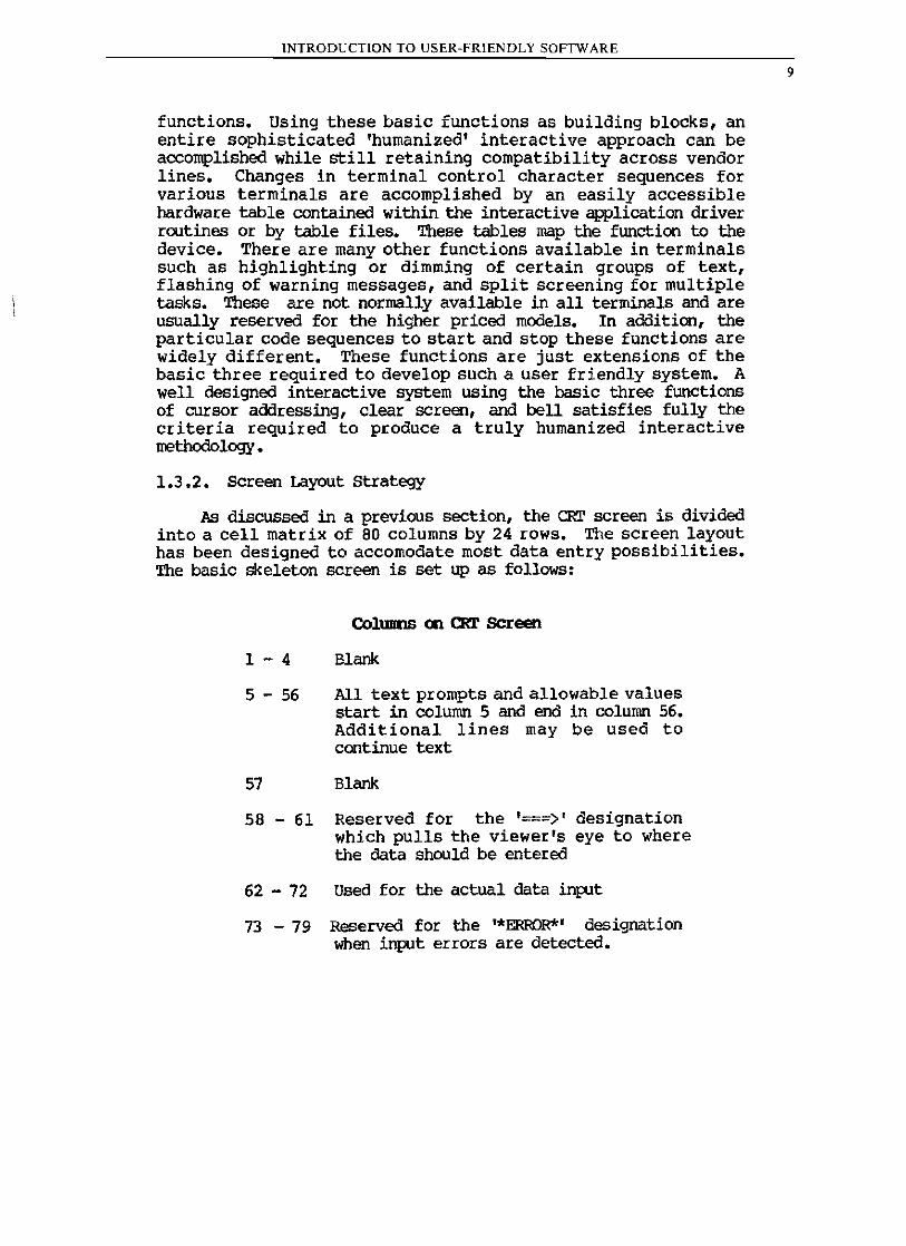
As discussed in a previous section, the CRT screen is divided into a cell matrix of 80 columns by 24 rows. The screen layout has been designed to accomodate most data entry possibilities. The basic skeleton screen is set up as follows:
COl.ums en eRr screen
1 - 4 Blank
5 - 56 All text prompts and allowable values start in column 5 and end in column 56. Additional lines may be used to continue text
57 Blank
58 - 61 Reserved for the '===) , designation which pulls the viewer's eye to where the data should be entered
62 - 72 Used for the actual data input
73 - 79 Reserved for the '*ERROR*' designation when input errors are detected.
9
10
INTRODUCTION TO USER-FRIENDLY SOFTWARE
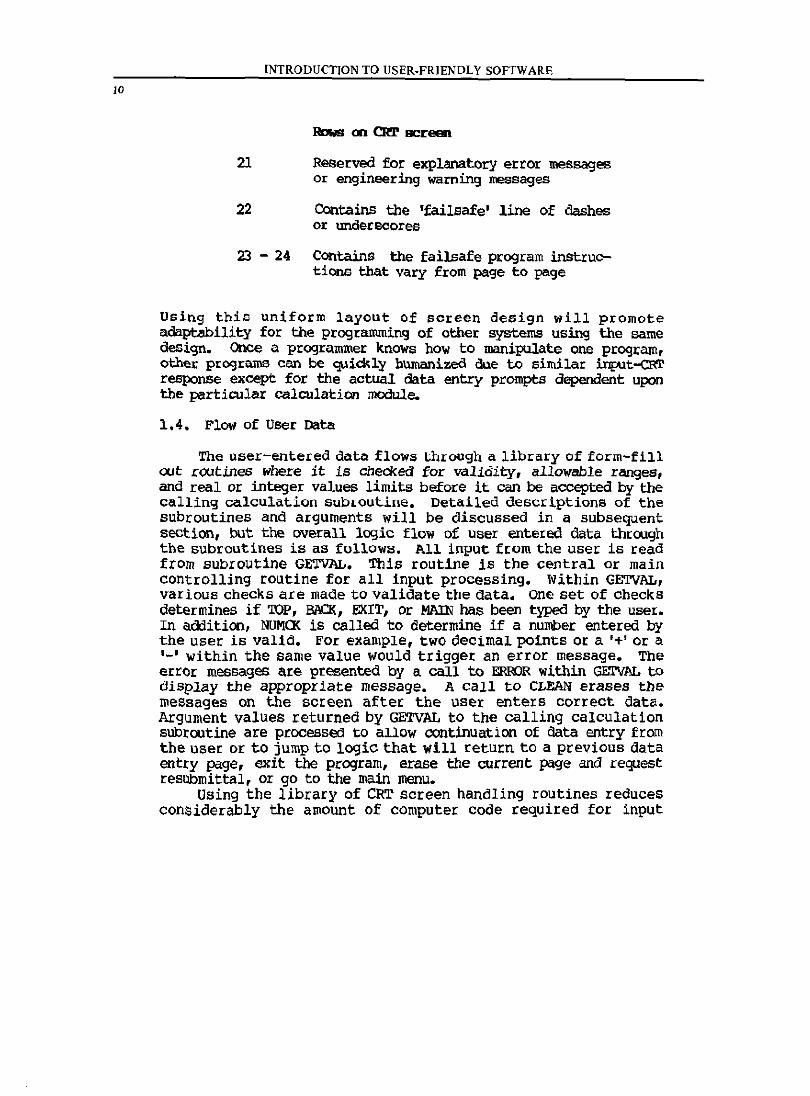
21 Reserved for explanatory error messages Or engineering warning messages
22 Contains the 'failsafe' line of dashes or undereoores
23 - 24 Contains the failsafe program instructions that vary from page to page
Using this uniform layout of soreen design will promote adaptability for the programming of other systems using the same design. Once a programmer knows how to manipulate one program, other programs can be quickly humanized due to similar i.rItAlt-cRl' response except for the actual data entry prompts dependent upon the particular calculation module.
1.4. Flow of User Data
The user-entered data flows through a library of form-fill out x:outines where it is checked for validity, allowable ranges, and real or integer values limits before it can be accepted by the calling calculation subloutine. Detailed descriptions of the subroutines and arguments will be discussed in a subsequent section, but the overall logic flow of user entered data through the subroutines is as follows. All input from the user is read from subroutine GETVAL. This routine is the central or main controlling routine for all input processing. Within GETVAL, various checks are made to validate the data. One set of checks determines if 'lOP, BIlCK, EXIT, or MAIN has been typed by the user. In addition, NUMCK is called to determine if a number entered by the user is valid. For example, two deci.mal points or a '+' or a '-' within the same value would trigger an error message. The error messages are presented by a call to ERROR within GEI'V1\L to display the appropriate message. A call to CLEAN erases the messages on the screen after the user enters correct data. Argument values returned by GETVAL to the calling calculation subroutine are processed to allow continuation of ctata entry from the user or to jump to logiC that will return to a previous data entry page, exit the program, erase the current pqge and request resllbmittal, or go to the main menu.
Using the library of CRT screen handling routines reduces considerably the amount of computer code required for input
INTRODUCTION TO USER-FRIENDLY SOFTWARE
processing. Since the arguments feeding GETVAL setup permissible ranges, and other parameters unique to a certain input item, the only READ statement for input (for all input it.ems) is contained within GETVAL. All the logic that processes errors and displays messages is contained within ERroR and CLEIIN. 'l11e area or columnrow address of the CRT screen where the current input item resides is passed through all the form-fill out routines in order that error messages and re-enter prompts can be addressed to the CRT correctly. In this general fashion, all input following the basic skeleton frame for the CRT 'pages' can be processed very efficiently.
1.5. Screen Design Method
The design of CRT interaction pages that will be presented to the program user for data entry requires a thorough design process in itself to be effective. An approach which has been used successfully in implementing production quality software is described in this section. The first step in the screen deSign process is to define all input entry prompts for a given function or calculation model. This is absolutely necessary in order that the screen designer may group related data entry prompts in a logical fashion. This global definition phase of prompts also helps to eliminate redundant data entries.
The wording of the prompt for single data items or value should start with 'Enter' followed by the information request text which is then followed by the 'units' designation. Data entry prompts which require a choice among several listed options demands a different strategy. The general title or description of the options is written first. The options are indented and listed below the title. Finally, the prompt starting with 'enter' or 'select' is written which describes the value being requested.
Any descriptive text that will precede prompts excluding the actual prompt must be defined for all input requests. The descriptive text is extremely helpful to first time or occasional users. The text should be very concise and offer a description of what is to follOW in the prompt. After additional explanatory text is defined, all prompts must be inspected and assigned allowable values. This range of values should be set to restrict each prompt to a typical or normal range of values that the user may enter. For option selection prompts which provide choices, only those stated values are permitted. A value outside this range represents an incorrect data response and will be handled by an error message and corresponding re-enter request for data. After all admissible values are defined, any suggested values that may help the user should be defined for each prompt. These values
11
12
INTRODUCTION TO USER-FRIENDLY SOFTWARE
may be typical values given a certain criteria or possibly a reviewing agency-dependent suggested value for a certain input item.
1.6. Subroutine Descriptions and Listings
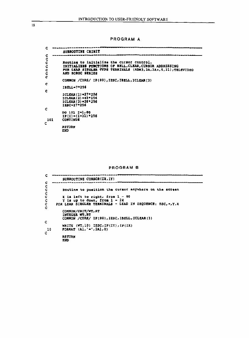
1.6.1. SUBROOTINE CRINIT
lIbstract
CRlNIT initializes the terminal control tables fo~ functions of clear screen, cursor addressing, and bell.
The routine contains all codes necessary to set up the screen functions. After the control codes have been determined for the terminal selected, these values are then loaded into the IP and ICLEAR arrays. The IP array contains the ASCII value required for positioning the cursor from I thru 80 on the CRT screen. ICLEAR array contains the ASCII codes to clear the screen. IESC is loaded with the lead-in character for the cursor addressing sequence. IBELL contains the code to exite the bell function on the terminal. The terminal codes set up in the listing are compatible with Lear Seigler, Televideo, and SOIlOC terminals. 'lbe ASCII values of the terminal functions are stored in common block CURS for availability throughout the library of screen subroutines. CRINIT is called once to set up the codes.
None.
1.6 .2 • SUBROOl'INE CUROOR
Abstract
positions the cursor anywhere on the CRT screen.
Description
Receives arguments of column, row from calling subroutine to position the cursor before a write is performed on the screen. 'l'he column, row argument is used as indices to the IP array table to select the appropriate ASCII codes. The write statement submits the ASCII string of characters to the screen for cursor
INTRODUCTION TO USER-FRIENDLY SOFTWARE
positioning. The Z (computer dependent) in the format statement holds the cursor after postioning for subsequent writes or prompts. SOme systems will not need the Z type of specification in the format statement.
(IN)
IY (IN)
ColllIIl'\ 11Ulli:>er (1-80)
Row Ill.IIlber (1-24)
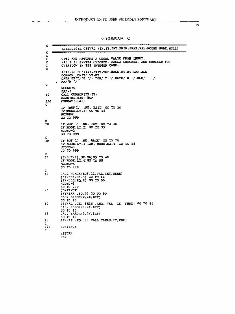
1.6.3. SUBROOTINE GE.TVAL
lIbstract
Central data inpJ.t capture routine which gets and returns a legal value from user input.
Input is received in an ll-character buffer (BUF) in Alpha format. The buffer is first checked for any legal function such as TOP, BACK, or EXIT. Depending on MODE, certain functions will not be legal at certain times. NUMCK is called to transform the alpha characters into a legal real value. If an error occurs, ERroR is called to display a message. The logic remains in GETVAL until the error is corrected, after which CLEAN is called to erase the previous error messages.
Arguments
IX (IN)
IY (IN)
INl' (IN)
FMIN (IN)
FMAY (IN)
VAL (~
ColllIIl'\ mmber to read on CBT screen
Row nUlltJer to read on CRI' screen
o = Read data input anticipated 1 = Integer data input anticipated
Mininum allowable value-passed to IUK:K
Maxinum allowable value-passed to NtJM(](
Legal, checked real value returned to calling routine
I3
14
NULL
INTRODUCTION TO USER-FRIENDLY SOFTWARE
(0Ul') 1 '" EXIT input by user
(IN)
(IN)
2 - TOP input by user 3 ~ BAa<: input by user 4 = MAIN input by user Values returned to calling routine for appropriate action
1 = allow EXIT 2 '" allow EXIT, TOP 3 = allow EXIT, TOP, BI\O{ 4 ~ allow EXIT, TOP, MAIN
o = do not allow blanks as input 1 = allow blanks as input, but set VPJ., = 0 at this occunence
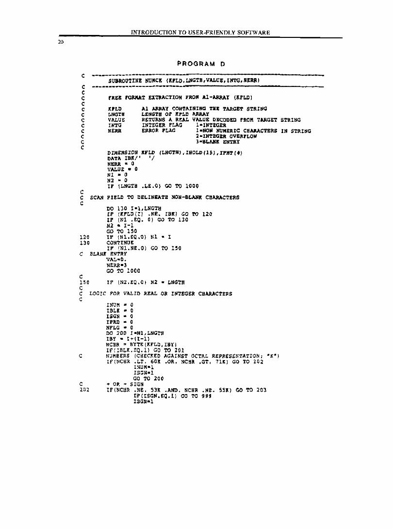
1.6.4. SUBRCUrINE NKl<
Abstract
Extensively checks a data inplt value (numeric) for legal syntax.
Descriptioo
The user data input is received in alpha format in buffer KFLD. !<FLD is then checked character by character to determine a legal numeric form. If the form is legal, KFLD is transformed by ENCODE and DECODE operations to a REPJ.. value. If an integer is expected, range chet%s are performed to assure an integer between -32767 and 32767.
KFLD
VAWE
INI'G
NERR
(IN)
(IN)
(our)
(IN)
(OO!?
Alpha buffer containing user data input
Length of KFID, usually 11
Real value returned to calling routine
Integer flag, 0 = floating point, 1 '" integer
Error flag, set to various values if an error occurs
INTRODUCTION TO USER-FRIENDLY SOFTWARE
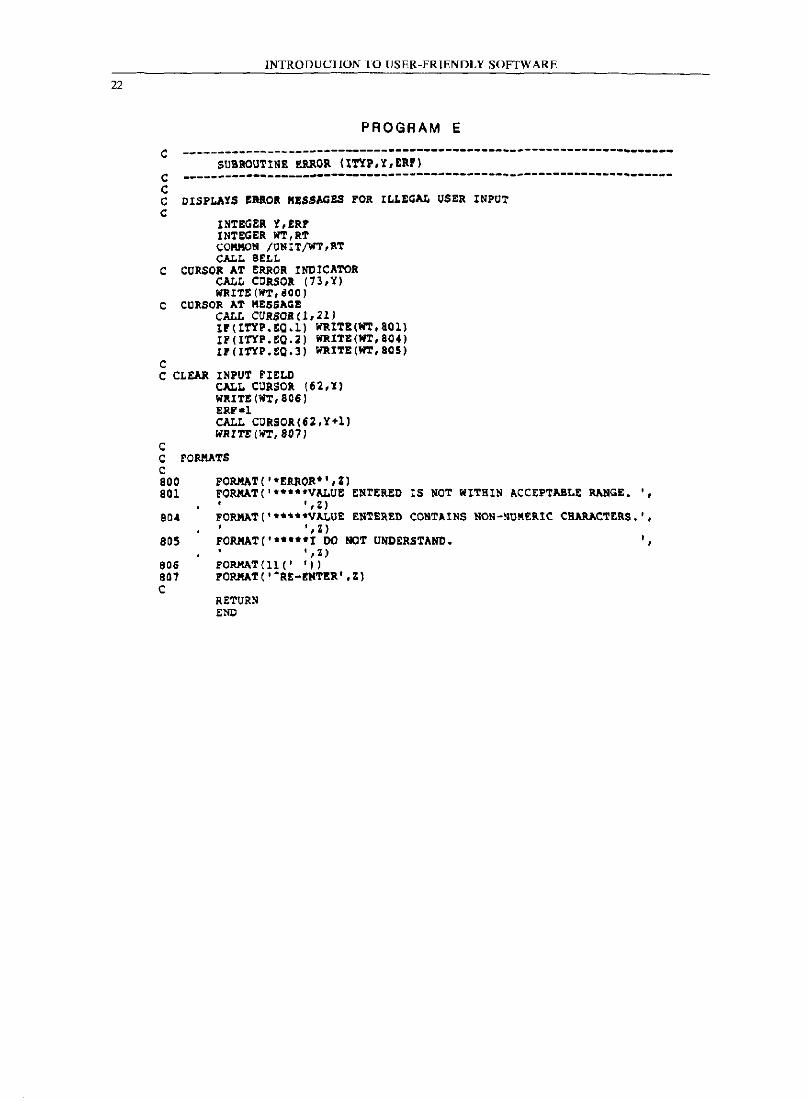
1.6.5. SUBROUTINE ERROR
Abstract
Contains a set of error messages which appear in a reserved row on the CRT sCreen for illegal data entries.
Descripti.cn
Displays any of three error messages in row 21. The '*ERROR*', and 'RE-ENl'ER' designations awear in columns 73-79 of the row of the data entry prompt and columns 62-70 of the row immediately below the input field. Selection of the particular error message displayed is controlled by GElVAL.
ITYP
y
ERF
(IN)
(IN)
(OUT)
Error message type to display
Row nll!lber of CUrrent data entry pronpt
Set to 1 when error message is displayed. CLEAN will reset it to 0 after the messages are erased.
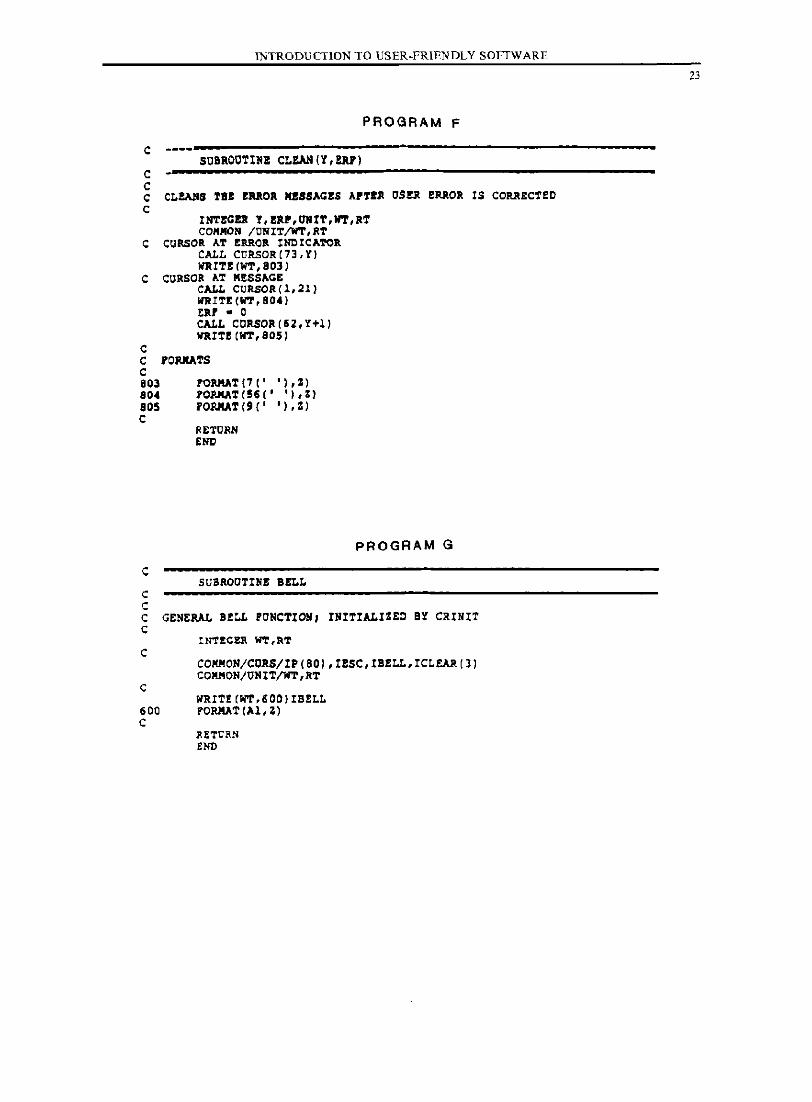
1.6.6. SUBlalTINE CLEAN
Abstract
Erases and cleans the sCreen of previous error messages.
Descriptim
Routine is called by GETVAL when user input error has been corrected. CLEAN clears the '*ERROR*' I 'RE-ENTER', and any message residing in row number 21 of the CRT screen.
MguDl!nts
Y
ERF
(IN)
(OUT)
Row number of current data entry prompt
Set to 0 upon exit to indicate messages have been cleared
15
16
INTRODUCTION TO USER-fRIENDLY SOFTWARE
1.6.7. SUBROOTINE BELL
Abstract
Produces an audible 'beep' to the terminal when user il1[lUt error is detected.
Descdption
Routine is called by ERROR. The ASCII bell code contained in lBELL is initialized by CRINIT.
None.
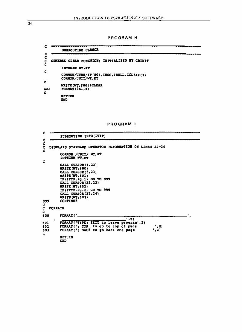
1. 6 • 8. SlJBR(.Ul'INE CLRSCR
Abstract:
Clears and erases all infomation on the CRr SCreen.
DeSCriptiCll
Routine is called throughout program whenever clearing the screen to blanks is required. ICLEAR is set to the ASCII clear screen codes initialized in ClU][rT.
1.6.9. SUBROUTINE INFO
lIbBtract
Displays failsafe information on last 3 rows of CRT screen.
DeSCription
Row number 22 is always filled with underscores to create a line an the screen. Rows 23 and 24 contain q>erator instructions that may vary depending on the value of ITYP. Within the program system, calls to place various text in this area are performed whenever additional or revised operator instructions are required.
ITYP (IN)
INTRODUCTION TO USER-FRIENDLY SOFTWARE
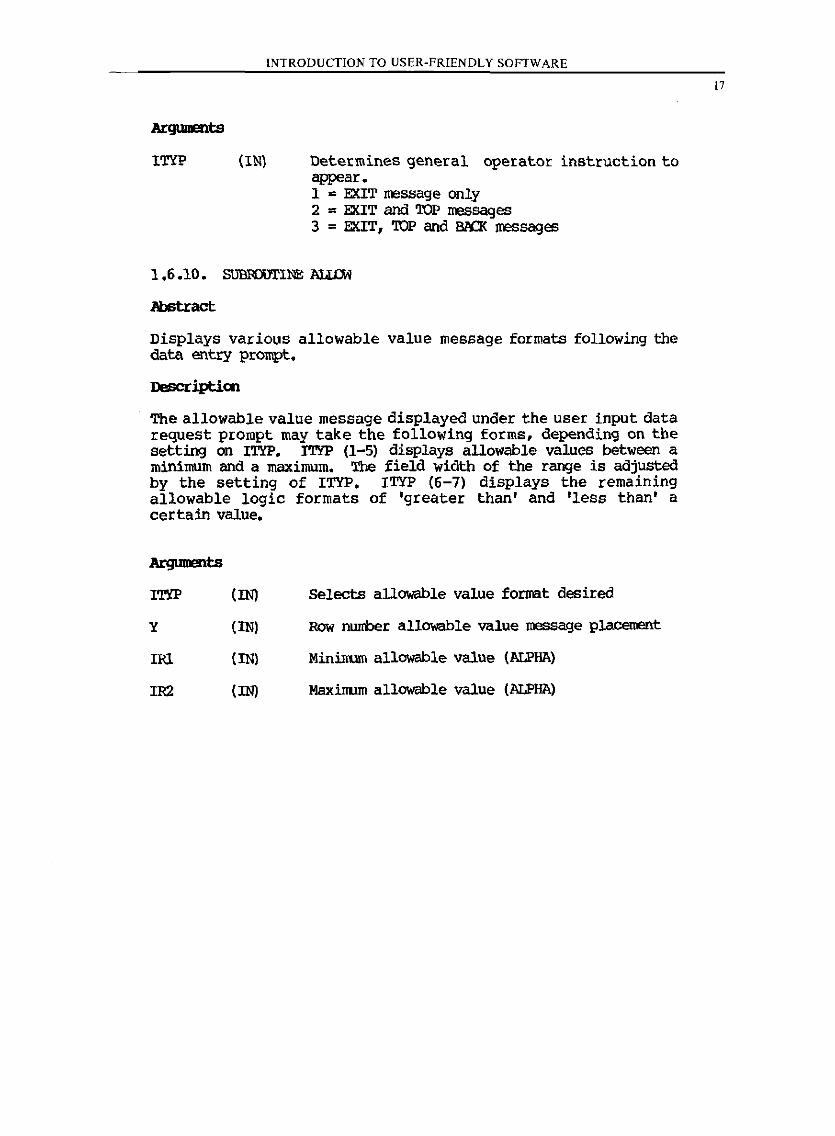
Determines general operator instruction to appear. 1 = EXIT message only 2 ., EXIT and TOP IreSSages 3 = EXIT, TOP and Bl\CK messages
1.6.10. SUBroUTINE lIIIDi
Displays various allowable value message formats following the data entry prompt.
Descriptioo
The allowable value message displayed under the user input data request prompt may take the following forms, depending on the setting on ITYP. ITYP (1-5) displays allowable values between a minimum and a maximum. The field width of the range is adjusted by the setting of ITYP. ITYP (6-7) displays the remaining allowable logic formats of 'greater than' and 'less than' a certain value.
y
IRl
IR2
(IN)
(IN)
(IN)
(IN)
Selects allowable value format desired
Row 1'lL1I£ber allowable value message pJ.acement
Minimum allowable value (ALPHA)
Maximum allowable value (ALPHA)
17
18
INTRODUCTION TO USER-FRIENDLY SOFTWARE
PROGRAM A
C -------------------------------------
C C C C c C C
c
C
C
SOIIOOTINI ClIMIT
--------------,----"-----------------------------------------------Routta, to inittalt •• IBITIALll18 raRCTtOKS POll LEAR IIIc:LU 'l'YPe A1IIl salce suus
the cur.or concrol. or BILL,CLEAR,CORaCl ADDRESSlNG fERIIINALS (ADM3.JA,JA+.S.31I,TELEVIDEO
CONNON ICORSI IP(SD),IESC,IIILL,ICLEAR(J)
IUU-7*25S
ICLEAR(1)-Z7*Z!. IC~EAa{Z)-41·:S' ICLEAa(l)-16*25& USC-27*256
DO 101 1-1,$0 IP(I)-(I+ll)*Z5&
101 COIITINDI C
C
C C C C C C C C
C
RETOaN END
PROGRAM B
-------,--------------------scalOUTINE CURSoaCIX.II)
x 1. left to r1jb~, from 1 - 80 Y i. up to down, froa 1 - 24
FOR LEAR SIIGLER TERMINALS - LEAD IN SEQOINCI: ESC,-,y.X
COKNON/~IT;wr,aT IlI'1'EGU 1I'r, aT CONNON ICURSI I.(BO).IESC.IB!LL.ICt!AR(3)
WRITE (WT.ID) IESC.I~(Iy),I.(IX) 10 POIUlAT (Al, '-'.2Al.t)
C RETORli END
c C C
INTRODUCTION TO USER-FRIENDLY SOFTW ARE
PROGRAM C
SUBROUTINE GETVAL CIX,Iy,INT,FKIN,FMAX,VAL,NCOND,MODE,NULLI
C G~S ANO RETURNS A LEGAL VALUE PROK INPUT. C VALUE IS SYNTAX CHEClED, ~GE CHEClED, AND CHEClED rOR C OVtllfl.OW IN TUB INTEGER eME. C
c
IN~EGER BOP(11),£XIT,TOP,8ACI,WT,RT,ERr,8L~ COHHON /UNITI WT,RT DA~A EXIT/'E 'I, TOP/'~ '/,BACKj'B '/.BL~/' 1/. W'K '/
NCOND-O ERt-O
1Q CALL CURSOR(IX,IY) READ(RT,520) eup
520 rORKATIIIA1) e
C
IF (BOI'(l) .NE. EXIT) GO TO 20 II'IMODE.LT.l) GO TO 55 KeaND-l GO TO 9U
20 IF(BUFtl) .NE. TOP) GO TO 30 Ir (MODE.U.2) GO .10 55 NCOND-2 GO TO 999
C 3D IF(BUP(l) .Nt. BAC!:) GO TO 70
IF(MOnE.LT.3 .01'.. MODE.EQ.4) GO TO S5 NeOND-3 GO TO 999
C 70 IF(BUf(l).NE.MA)GO TO 40
IF(MODE.LT.4IGO TO 55 ~COND·' GO TO 999
C 40 CALL NUMCX(BUr,ll,VAL,INT,NERR}
IF(NERR.NE.31 GO TO 42 tr(NULL-.EQ.O) GO TO 55 ~COND.S GO TO 1199
42 CONTINUE IF(NERR .EQ.O) GO TO 50 CALL ERROR(2,IY,ERP) GO TO 10
sa rrlVkr. .Gg. F!{HI .A!!D. VAL .LE. FMl<1 GO 'l'O 60 CALL ERROR(l,I~,!RF) GO TO 10
SS CALL ERROR(3,IY,ERFl GC TO 10
60 IF(tR? .EO. 11 CALL CLEAN(lY,ERf) C 999 CONTINUE C
19
20
INTRODUCTION TO USER-FRIENDLY SOFTWARE
PROGRAM 0
c ------------------------------c c c c c c c C C C C C
C
SUBROUTINE NUKCK (IPLD.~GT8,VALUB.INTG,HERR)
---------------------------rass rORKAT EXtaACTION FROM Al-ARRAY (lFLD)
Inn LNGTB VALU~ INTG NERR
Al ARRAY CONTAINING THE rARGEr STRING tE~GTa or KFLn ARRAr RETURNS A REAL VALUE DECODED FROK TARGET INTEGER FLAG I-INTEGER ERIIOR PLAG I-NON NUMERIC CHARACTERS
2-INTEGER OVERFLOW 3 -SLAliIt ENTRY
DIMENSION KFLD (LNGTH),IHOLn(lS),IPMT(f) DATA 11111' • / NERR • 0 VALUE - 0 HI • 0 N2 • 0 IF \tNGTH .LE.O) GO TO 1000
C SCAN PIELn TO DELINEATE NON-BtAHR CHARACTERS C
DO 130 I-I,LNGTH IF (IPLO(!) .NE. lSI} GO TO 120 IF (Nl .EQ. 0) GO TO 130 N2 - I-I GO 'l"o ISO
120 IF INl.Ee.O} Nl - I 130 CONTINUE
IF INl.NE.O} GO TO 150 C SLAHl!: EH'l'lIY
VAL-C. N!:lU\') GO TO 1000
C 150 IF IN~.EQ.O) N2 - LNGta c C LOGIC FOR VALID REAL OR IN'l"EGER caARACTE~S C
INUM - 0 I8U ·0 I5GN • 0 IPRI) • 0 NfLG • 0 DO 200 r-Nl,LNGTS ISY - I~(t-l) NCBR • 8YT£(XF~O.lBY) IfIIBLK.EO.l} GO TO 201
C N"MBERS IC~tCKEO AGAINST OCTAL REPRESENTATION; OK") IflNCHR .LX. GOl .OR. NCBa .<iT. 71K) GO TO zo~
I~UM·l ISGN·l GO ro .00
C + OR - SIGN 202 IF(NCHR .NE. 531 .AND. NCHR .NE. 551) GO TO 203
rr(rSGN.£Q.L) GO TO 999 ISGN-l
STRING
IN STRING
INTRODUCTION TO USER.FRIENDLY SOFfWARE
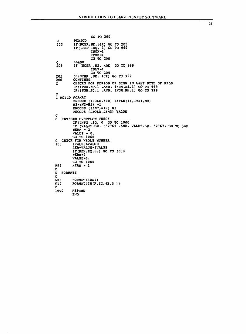
GO TO 200 C PERIOD 20l If(NCBR.NE.56Kl GO TO 20S
If(IPRD .EO. 1) GO TO 999 15GN-l I!'RI)-l GO TO 200
C BLAN! 205 If (NCER .NE. CO!l GO TO 999
IBLK-l GO TO 200
201 rF(HCHR .NE. COl) GO TO 999 200 CONTINUE C CHECKS FOR PERIOD OR SIGH IN LAST BYTE OF KFLD
IF(IPRO.EO.l .AND. IHUR.HE.l) GO TO 999 lr(IS0H.EQ.l .AND. lNUR.HE.l) 00 TO 999
c C BOILD fOIUtAT
c
tNCOOE (ISOLD,6DO) (KPLDII) ,I-Nl,N2) 1/3-(1/2-111) Tl ENCODE (IrMT,610) Nl DECODE (IBOLD,IFMTl VALOE
C INTEGER OVERFLOW CSEC! Ir(INTC .EO. 0) GO TO 1000 IF (VALUE.CE. -32167 .AND. VALUE.LE. 32161) GO TO 300 NERR - 2 II"LUE - O. GO TO 1000
C CSEC! FOR waOLE NUMBER 300 IVALOE-VALUE
REM-VALUE-IVALOE 11(II£M.£0.0.) GO TO 1000 NERR-2 VALOE-O. GO TO 1000
999 NI:RR - 1 C C FORMATS C 600 FORMAT {30All 610 FORMAT(2BIF,I2,CH.0 I) C 1000 R£TUIIN
END
21
22
c c c C C
C
c
C
INTRODUCIJON TO USER-FRIENDLY SOFTWARE
PROGRAM E
-----------------------------------------------~---------------------SUBROUTINE ERROR (ITYP,l,ERP) ------------------.--------------------------~-----------------------DISPLAYS ERROR MESSAGES FOR ILLEGAL USER INPUT
INTEGER r,ERr INTEGER liT,RT COMMON /UNIT/WT,RT CALL BELL
CORSOR AT ERROR INDICATOR CALL CORSOR (73,Y) WRITE (WT,dOO)
ceRSOR AT MESSAGE CALL CURSOR!l,'l) IF(ITYP.EQ.l) WRITE(WT.aOl) IP(ITYP.EQ.2) WRITE(WT,804) Il(ITYP.EQ.J) WRITE(WT,8QS)
C CLEAR INPUT rIELD
C
CALL CURSOR (62,l) WRITE(WT.806) EU-l CALL CORSOR(62.Y+l) WRITE (liT, 807)
C FORMATS C 800 FORMAT("ERROR",Z) 801 FORMAT('·····VALUE ENTERED IS NOT WITHIN ACCEPTABLE RANGE. "
f I , Z ) 804 FORMAT('.···.VALUE ENTERED CONTAINS NON-~UMERIC CBARACTERS.',
I I .. Z ) 80S FORMAT (. • .... 1 DO NOT UNDERSTAND.
, ! .. Z)
606 FORMAT (11 (' .» 807 FORMAT ( '"RE-EIITER' • Z I C
RETURN END
INTRODUCTION TO USER-FRIENDLY SOFTWARE
PROGRAM F
C SUSROC1IN! CLEAN(Y,tRP)
c C C CLEANS TBI rRaOR KBSSAC!S APTIR crS!R fRaOR IS CORRECTED C
INT!CER Y,!RP,OMIT,WT,RT COMMON ICNIT/WT,RT
C CORSOR AT ERROR INDICAi'Olt CALL CURSOR(73,1) WRITE (WT,80J)
C CORSOR AT K!SSACE CALL CORSOR(l,~l) IfRITE(W'l',804) ERr. 0
c
CALL CCRSOR(52,Y+l) WRIT! (W'l',805)
C rOIUlATS C 803 FOlUtAT {7 (' '), Z) 804 10lUtA'1'(56(' 'I,Z) 805 FOlUtA'1' (9( I ,), Z) C
c c c
SUBROOTINE BELL
PROGRAM G
C GENERAL BELL PONCTION, INITIALIZED BY CRINIT C
c
c
COKMON/CCRS/IP(BO),I!SC,IBELL,ICLEAR(3) COKMON/UNIT/WT,RT
WRITE (WT,600)IBELL 600 POlUtAT(Al,Z) C
RETCRN END
23
24
C
C C
INTRODUCflON TO USER-FRIENDLY SOFTW ARE
PROGRAM H
------------------------------------------------------... _------SOIlOOTI51 C~CR
----~~~~~~----------------------------------------------C GSREIAL CLIAa POIC!lON, INITIALIZeD IY CRINIT C
C
c:
I_a 1I'l',a1'
CORRON/Coas/I.(IO),IISC,IBILL,ICLEAR(3) COKRON/ONIT/WT,RT
WRITE(WT,'OO)IC~EAIt 100 rORRAT(3Al,l) C
C
C C
RrrDltH !ND
SOBROOTIN! IMPO(ITY')
PROGRAM
C OIS.LAYS STANDARD O.IRATOR INPORRATION OR LI.rs 22-2' C
C
CORRON /ONIT/ NT,aT IHTI!l1Ul lI'1',a'l:
CALL CORSOR(l,22) WRITE (11'1',600) CALL coasoaC5,23) waITICWT,I01) IP(ITYP.EQ.l) GO TO '" CAL~ CURSORC33,23) WRITE (11'1', 102) IPCITYP.EQ.2) GO TO '" CALL COSSOR(33,24) WRIT! CWT. 603)
'" CONTIND! C C PORRATS C 600 ruORRA:;~T~C~'~~~;;;;~:;::::~~~~~ ________________ __ '= I,Z) 601 rOlAATC'TYPE. EXIT to leave program',Z) 602 POlAATC', TOP to go to top of page ',ZI 603 POlAATC'; BACK to go back one page ',Z) C
aETO .. END
INTRODUCfION TO USER-FRIENDLY SOFTW ARE
PROGRAM J
c -----------,-------------------c c
SUBRODTINB ALLOW (ITYP, Y, IRl, IR2)
C D1SPLA%S ALLOWAiLI VALUE MESSAGES C
D1KII810N IRl(5),IR2(S) 1II'UGIR NT, R'1' COMMON /OIlI'1'/W'l',R'l'
C CORSOR AT PLACEKEN'1' OF ALLOWABLE MESSAGE CALL CORSOR(S,Y)
C
C
1P(ITYP.EQ.l) WRI'l'E(NT,aOl) 1R1(1),(IR2(1),1-1,J) IF (ITYP.EQ. 2) WRI'l'E (NT, a02) IR1 (1) dIa2 (I) ,1-1,5) 1P(I'l'YP.EQ.J) WRI'l'E(W'l',80J) (IR1(I),I-l,J),(IR2(I),I-l,J) IP(ITYP.EQ.4) WRI'l'E(W'l',a04) (IR1(I),I-l,1),(IR2(1),I-l,5) IP(ITYP.EQ.5) WR1'1'!(W'l',aos) (IR1(1),I-l,S),(IR2(1),I-l,S) 1P(ITYP.EQ.6) WR1'1'B(W'l',a06) (IR1(I),1-1,1) IF (ITYP.EQ.7) WRI'1'E(W'l',a07) (IRl(I),I-l,l)
C POIUlA'1'S C aOl POIUlA'1'('.ALLOWAILB VALOES ARE (',AI,') '1'0 (',lA2,"') 802 POIUlAT (' .ALLOWABLE VALOES ARB (' ,Al, '] '1'0 (', 5A2, " ') a03 POIUIA'1' (' .ALLOWABLE VALUES ARE ('. 3A2, '] '1'0 (', JA2,', ') 804 POIUlA'1'('.ALLOWABLE VALUES ARE (',3A2,'] '1'0 (',5A2,']') aos FOIUlAT('.ALLOWABLE VALUES ARE ('.SA2.'] '1'0 ('.5A2,']') 806 POIUlAT('.ALLOWABLE VALDES ARB GREATER THAN (',3A2,'I') a07 POIUlA'1'(':ALLOWABLE VALUES ARE LESS THAN (',JA2,'I') C
RE'l'UltN END
25
CHAPTER TWO
CLASSIFICATION
OF OPEN CHANNEL FLOW
2.1. Definitions
Several forms of open channel flow can be classified according to whether the flow is steady or unsteady, and uniform or nonuniform. For a sufficiently long channel of constant cross section (i.e., a regular or prismatic channel) and of constant channel slope, and where a constant flow enters the channel for all time, then a steady uniform flow typically occurs within some portion of the channel length. Where the flow regime stabilizes in the channel such that a terminal velocity is reached, the flowdepth corresponding to this stabilized steady uniform flow is called the normal depth. Consequently, steady uniform flow in a reach of channel is characterized by (1) a constant flow rate in the prismatic channel, and (2) the flow depth is everywhere constant in the channel reach. Several emperical equations have been developed to estimate normal depth; the Manning's equation is possibly the most widely used method (section 2.2).
Steady nonuniform flow occurs in a channel reach when the flow rate is a constant (i.e., steady flow) and the channel cross section is variable, or when the channel is prismatic but the flow depth is not stabilized and hence changes along the channel reach. When the flow depth variations are "gradual", gradually varied flow profiles can be developed which characterize the change in channel flowdepth along the channel reach.
26
CLASSIFICATIONS OF OPEN CHANNEL FLOW FUNDAMENTALS
In cootrast to steady flow, unsteady flow in an C9Erl channel occurs due to a time variable flowrate into a channel reach. '!be routing of a flood wave runoff hydrograph through a channel reach is an ~le of unsteady flow.
Open channel flow is further classified as subcritical, mild and tranquil, or as supercritical, steep and rapid. When channel flows occur at low velocities such that a disturbance wave can travel upstream on the water's surface, the flow is called subcritiCAl. Should the upstream portion of the disturbance wave remain stationary with respect to a fixed reference pOint, the flow 1s crIt1cal. Should the distumance wave be entirely washed downstream, the flow is called ~it1ca].
2.2. Manning's Equation
Based on experimental data obtained from studies on steady uniform flow, Manning's equation relates normal depth flow characteristics to the cbannel flow rate by (in English units)
(2.1)
where Q is the steady flow rate i~ cubic feet per second (cfs), A is the cross-section flow area (ft ), R is the hydraulic radius (A divided by the wetted perimeter, P), S is- the slope of the energy grade line, (which, when normal depth occurs, is equal to the channel slope) and n is the Manning's frictioo factor.
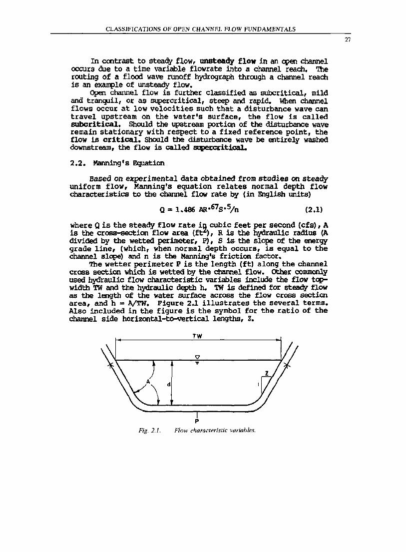
The wetter perimeter P is the length (ftl along the channel cross section which is wetted by the channel flow. other commonly used hydraulic flow characteristic variables include the flow tqlwidth TW and the hydraulic depth h. TW is defined for steady flow as the length of the water surface across the flow cross section area, and h = A/TW. Figure 2.1 illustrates the several terms. Also included in the figure is the symbol for the ratio of the channel side horizontal-to-vertical lengths, Z.
TW
d
p
Fig. 2.1. Flow characteristic variables.
27
28
CLASSIFICATIONS OF OPEN CHANNEL FWW FUNDAMENTALS
2.3. Froude NImtler
A convenient expression which represents the channel flow characteristics is the Froude nurrber F, where
(2.2)
In (2.2), V is the average velocity V = Q/A, g is 32.2 ft/sec2, and h is the hydraulic depth. Should a kinetic energy correction factor be included such as in Eq. (3.21), then (2.2) is modified accordingly.
The Froude number characterizes the flow regime by noting F > 1 for supercritical flow, F< 1 for subcritical flow, and F = 1 for critical flow.
2.4. Conputer Programs
Normal depth and critical depth flow calculations are provided in PROGRAM numbers 2 and 3 for steady uniform flow in trapezoidal, rectangular, V-shaped, and circular cross sections. Program features include the calculations for the several discussed variables, along with the estimation of specific energy and specific force values (sections 3.3.2. and 3.3.3.).
CHAPTER THREE
OPEN CHANNEL FLOW
3.1. Introduction
The study of open channel flow hydraulics requires an understanding of the fundamental principles embodied in the conservation of mass, momentum, and energy. Consequently, the basic definitions and equations need to be presented prior to developing the detailed computer software which can be applied to solving engineering problems. In the following, the necessary fundamentals of open channel flow hydraulics is briefly reviewed. These concepts will then be extended towards the development of comprehensive micl:ocomputer software for the analysis of steady flow in <:pen channels.
3.2. Conservation of Mass, Moirenturn, and Energy
The stUdy of open channel flow hydraulics is based upon the three cooservation laws of mass, momentum, and energy. These laws are applicable to a specified quantity of matter (or system) which preserves its identity while undergoing a change in pOSition, energy level, or other conditions.
The usual application of these laws is to develop integral equations which express the fundamental principles with respect to fluid flow through a control volume. The integral equations can be directly applied to flow problems or rewritten in terms of partial differential equations to analyze the assumed fluid continuum.
3.2.1. Conservation of Mass
For a fixed control volume II enclosed by the surface r , the integral form of the conservation of mass is given in vector
notation by J J pY • dA + a: p dll = 0 (3.1)
r II
where Y is the velocity vector with respect to the Cartesian coordinate system, and dA is the outward normal vector to r with magnitude dA. For steady flow the time derivative is zero, giving
29
30
For inconpressible flow
OPE'! CHANNEL FLOW
f pV • dA " 0
r
JV'dA=O
r
(3.2)
(3.3)
The differential ~tion form of mass conservation is often used in open channel flow hydraulics. This form 1s obtained by application of Gauss' theorem to (3.1) giving
ap 3 3 - + - (pu) + - (pvl at ax ay
a + - (pw) = 0
dZ
where (u,v,w) are the (x,y,z) directional flow velocities. steady, incOll1?ressible flow (3.4) reduces to
au all oW -+-+-"0 ax ay 3z
3.2.2. Conservation of Mo!rentum
(3.4)
For
(3.5)
Newton's second law of motion relates the net force upon a system to the change in l110llrantum M by
F acting
dM F= -
dt (3.6)
With respect to the fixed control volume n , (3.6) can be written in integral form as
J VpV • dA + a: J Vpdn = F
r n (3.7)
The F vector is composed of pressure and shear forces acting upon the surface of the system Fs ' and the body force vector
B which relates body forces (suen as gravity) per unit volume of the system. Using F 5 and B , (3.7) is rewritten as
dA + ~ J Vpdn " F 3t s
(3.8)
(l
For steady flow, (3.8)
OPEN CHANNEL FLOW
becorres
J VpV •
r
dA = Fs + J 8dll
\l (3.9)
An important application of (3.9) is when the fluid crosses r at only one point of entrance (point 1) and exit (point 2). JI.ssuming that the fluid density and flow velocity are constant over the entrance and exit areas, then (3.9) becomes
.
LFx = M(u z -u , )
l:Fy = M(V2
-v,)
LF "M(w - \'I ) z Z I
where M is the mass flowrate through \l.
3.2.3. Conservation of Energy
(3.10)
The first law of thermodynamics is used to develop the integral equation form of the conservation of energy. The conservation law is given by
dE " Q - W (3.11)
where dE is the change in the energy of the system, Q is the heat added to the system, and W is the work done by the system. The energy E is written in terI1f3 of several contributions by
E = U + imv2 + mgZ (3.12)
where U is the internal energy, m is the system mass, mV2/2 is the kinetic energy, and mgZ is the potential energy. For e = E;lm, (3.11) is written in integral equation form with respect to time by
dA + ~ J epdll :>t
Il
dQ dW =- --
dt dt (3.13)
31
32
OPEN CHANNEL FLOW
Flow work done on r due to normal stresses (hydrostatic pressure) can be isolated from the w term and (3.13) rewritten as
J a J dQ dW*
(e + pip) pV • dA + - epdn = -- - --at dt dt
(3.14)
r n where p is the fluid pressure and W* is the work term W less the flow work contribution.
For steady flow, (3.14) reduces to
f dQ dW*
(e + pip) pV • dA = -- - -dt dt
r
(3.15)
For one entrance (point 1) and exit (paint 2) associated to r , and coostant e.p,p over the entrance and exit areas,
(3.16)
Noting e = E;/m, and M being the mass flow rate through n gives
where i = U/m. Letting dQ • gH = (i - i ) - - I M
L 2 1 dt
dQ dW*
dt dt
(3.17)
(3.18)
further reduces (3.17) for zero system work and Pa= PI = p to
+ - Z ) + 9 H = 0 I L
(3.19)
p
Ot in terns of length units (or head)
( ) ( V2 _ V2) Pz - PI 2 I .......:~--=-- + --=~--=-- + (Zz - ZI) + HL = 0
y 29 (3.20)
whete Y is the fluid specific weight, and HL is the head loss.
OPEN CHANNEL FLOW
3.3 • Fundamentals of Hydraulics
3.3.1. Hydraulic Grade Line and Energy Grade Line
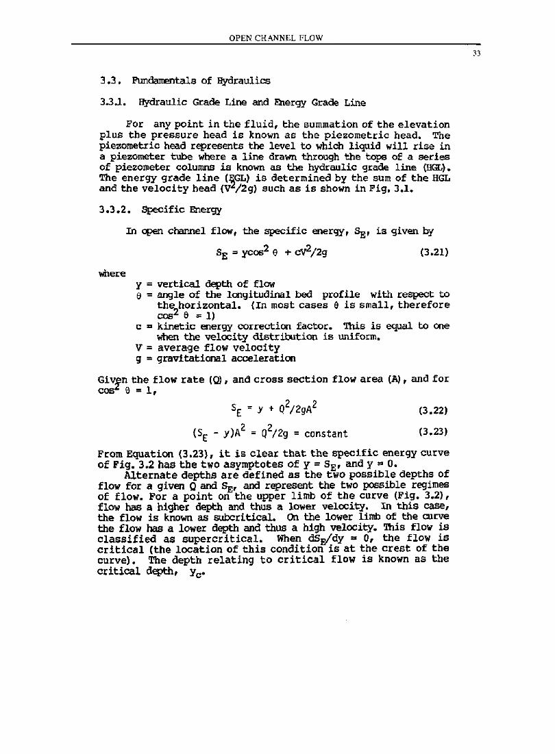
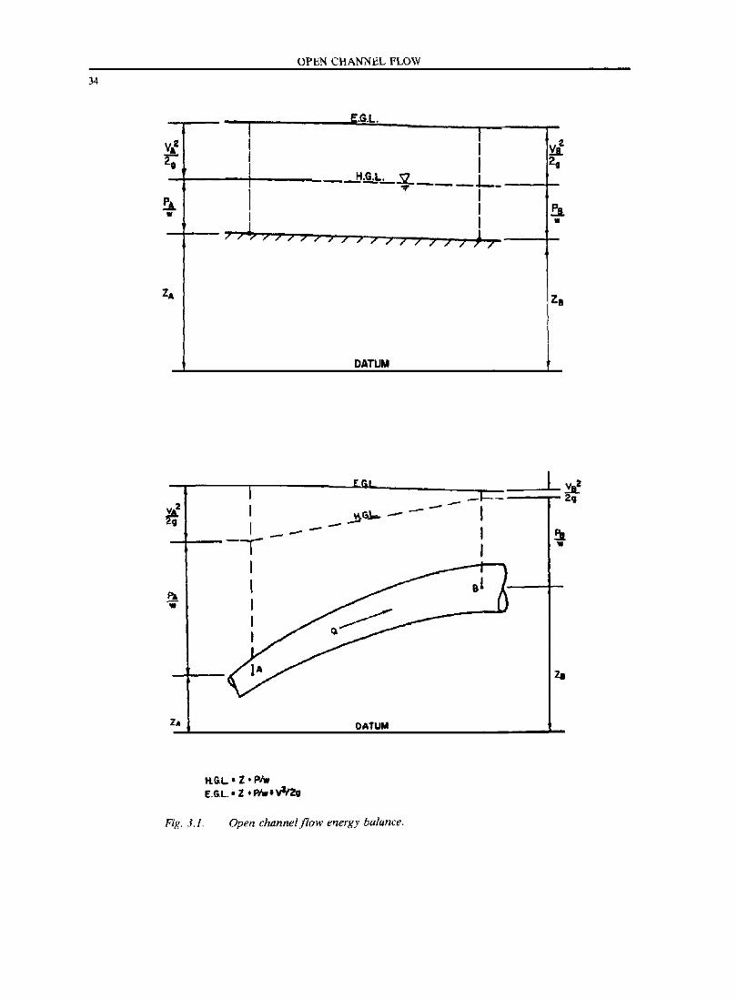
For any point in the fluid, the summation of the elevation plus the pressure head is known as the piezometric head. The piezometric head represents the level to which liquid will rise in a piezometer tube where a line drawn through the tops of a series of piezometer columns is known as the hydraulic grade line (HGL). The energy grade line (~GL) is determined by the sum of the HGL and the velocity head (V /2g) such as is shown in Fig. 3.1.
3.3.2. Specific Energy
where
In open channel flow, the specific energy, SE' is given by
(3.21)
y ; vertical depth of flow e " angle of the longitudinal bed profile with respect to
the2horizontal. (In most cases e is small, therefore
cos a = 1) c .. kinetic energy conection factor. '!his is equal to one
when the velocity distribution is uniform. V = average flow velocity g ; gravitational acceleration
GiV~m the flow rate (0), and cross section flow area (Al, and for cos e = 1,
SE : y + Q2/2gA2 (3.22)
(3.23)
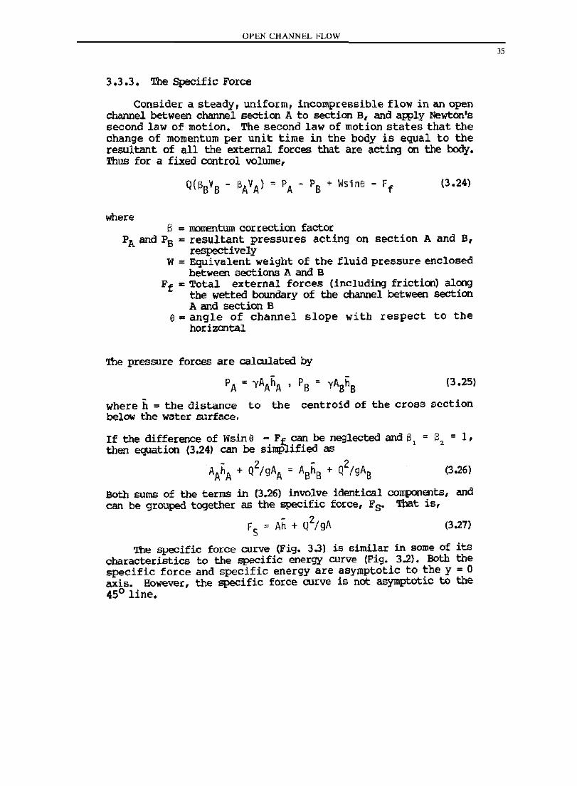
From Equation (3.23), it is clear that the specific energy curve of Fig. 3.2 has the two asymptotes of y = SE' and y = O.
Alternate depths are defined as the two possible depths of flow for a given Q and~, and represent the two possible regimes of flow. For a point on the upper limb of the curve (Fig. 3.2), flow has a higher depth and thus a lower velocity. In this case, the flow is known as subcritical. On the lower limb of the curve the flow has a lower depth and thus a high velocity. This flow is classified as supercritical. When dSEfdY ~ 0, the flow is critical (the location of this condition is at the crest of the curve). The depth relating to critical flow is known as the critical depth, Yc'
33
34
OPEN CHANNEL fLOW
E.G.l.
VA' I I V 0 I I 2,
i -ttg_. 5L L ... --- -
I • I I
L.. I • ;; ... ?;;;; ; ; ; 7 7 ; ; ) ; ) ) / )
z A ZB
DATUM
-lI------~-----------L~---------_=~:::====~~ 20
~02 I --
Fig. 3.1.
~~--I ------T I I I I I
H.~L.·Z·PIw E.~L' Z .P/wtvll2v
DATUM
Open channel flow energy balance.
OPEN CHANNEL FLOW
3.3.3. The Specific Force
Cons ide I: a steady, unifol:m, incompressible flow in an open channel between channel section A to section Bf and apply Newton's second law of motion. The second law of motion states that the change of momentum per unit time in the body is equal to the resultant of all the external forces that are acting on the body. Thus for a fixed control volume,
(3.24)
where S = momentum correction factor
PA and PB = resultant pressures acting on section A and B f
respectively W = Equivalent weight of the fluid pressure enclosed
between sections A and B F f = Total external forces (including friction) along
the wetted boundary of the channel between section A and section B
0= angle of channel slope with respect to the horizontal
The pressure forces are calculated by
PA = yAAhA ' PB = YAShS (3.25)
where h = the distance to the centroid of the cross section below the water surface.
If the difference of Wsin e - F f can be neglected and S 1 = then equaticn (3.24) can be simplified as
. - 2 - 2 AAhA + Q IgAA = ABhB + Q 19AB
S = 1, 2
(3.26)
BOth sums of the terms in (3.26) involve identical components, and can be grouped together as the specific force, Fs. That is,
F S = Ah + Q2/ gA (3.27)
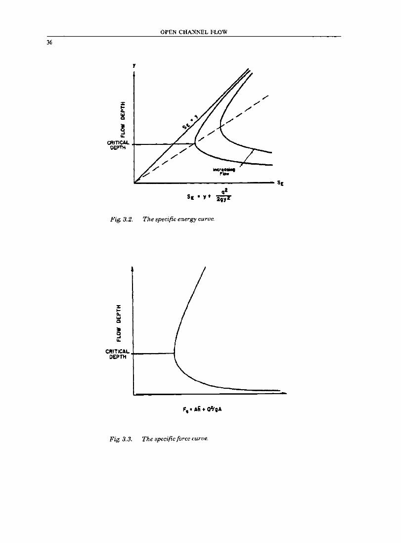
The specific force curve (Fig. 3.3) is similar in some of its characteristics to the specific energy curve (Fig. 3.2). Both the specific force and specific energy are asymptotic to the y = 0 axis. However, the specific force curve is not asymptotic to the 450 line.
35
36
:z: Ii: :!I
~
OPEN CHANNEL FLOW
y
CRITICAL +-----T~_::.{ DEPTH
~----------------------------SE
Fig. 3.2. The specific energy curve.
CRITICAL +-___ --1 DEPT"
Fig. 3.3. The specific force curve.
OPEN CHANNEL FLOW
3.3 .4. 'llle Hydraulic Jwrp in a Rectangular Channel
Solution of the continuity and momentum equations for the special case of a rectangular channel leads to the following relation for the initial (Yl) and sequential depths (Y2) of a hydraulic jump on a horizCCltaT floor:
(3.28)
and (3.29)
In the above, FI and F2 are the Froude numbers corresponding to depths Yl and Y2' respectively. Substituting these values into the energy equatl.on gives the energy loss in the jump
(3.30)
The junp efficiency E~l can be expressed as
E~El = «8F12 + ll3/2 - 4F12 + ll/8F1
2(2 + F12) (3.31)
'llle relative height of the jump (Y2 - YlllE:t can be expressed as
(Y2 - Y1)/E:t = «l + 8F12).5 - 3)/(2 + F12) (3.32)
The U.s. Bureau of Reclamation has classified various types of hydraulic jumps based on the Froude number, F. '!heir results are summarized below:
TABLE 3.1. HYDRAULIC JUMP CLASSIFICATIOR>
F
1 to 1.7 1.7 to 2.5 2.5 to 4.5 4.5 to 9.0
> 9.0
3.4. Gradually Varied Flow
Classification
undIIlar jwrp weak jwrp OSCillating jump steady jUIlp strong jUIll>
Gradually varied flow in a prismatic channel can be modeled by the one-dimensional differential equation
(3.33)
37
38
OPEN CHANNEL fLOW
Iohere y = flow depth
So = the bed slope Sf = the friction slape F = the Froude rumber x = coordinate along channel bottom
When Sf approaches So' dy/cix approaches zero. Therefore, water surface profiles approach the normal depth of flow asyrrptotically.
If F approaches unity, dy/dx awroaches infinity. 'lberefore, by (3.33), the water surface becomes nearly vertical.
3.4.1. S Profiles
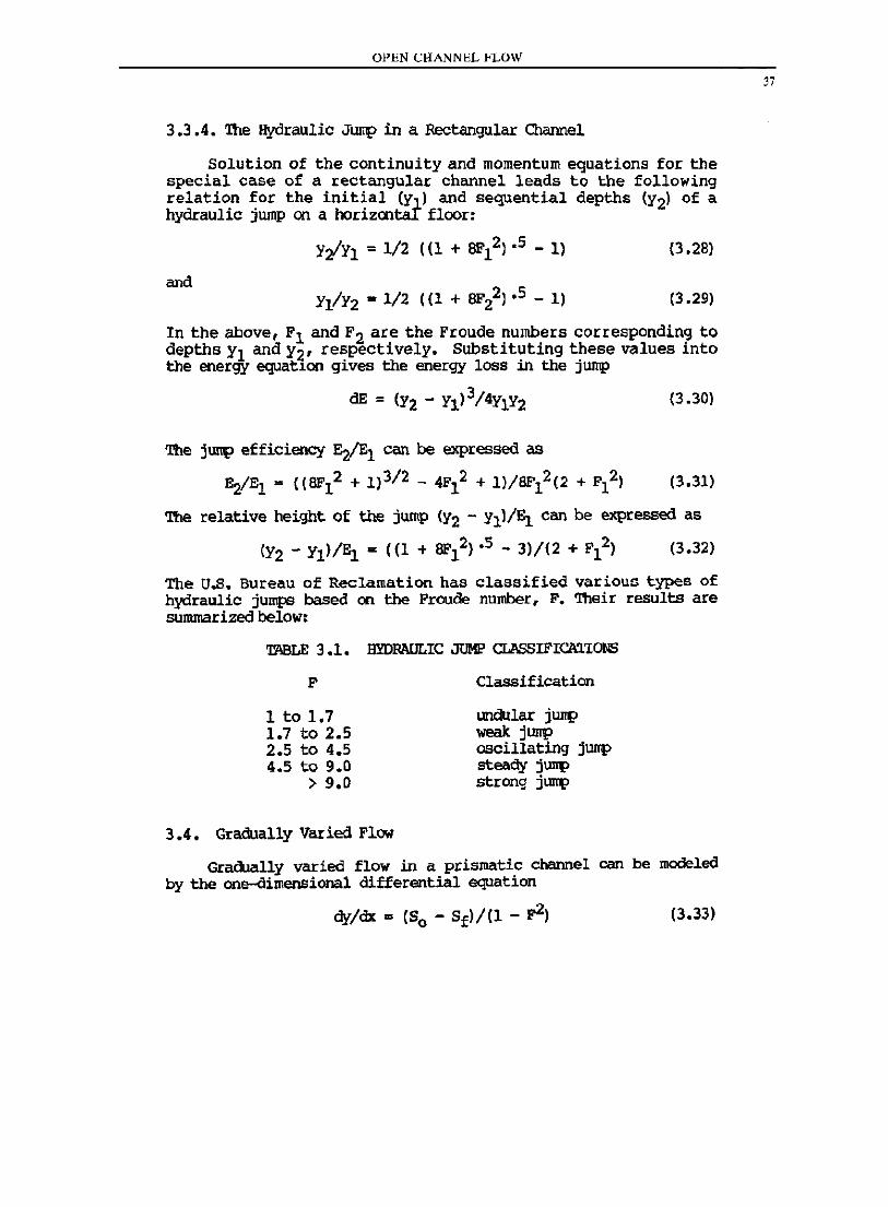
A channel is classified as steep for a discharge when the normal depth is less than the critical depth, and is mild when the normal depth is greater than the critical. When the normal flow is rapid (normal depth less than critical) in a channel, the resulting profiles Sl' S2 and ~ are known as the steep profiles. The Sl profile approximates gradUally varied flow which is above the normal and critical depths, S2 represents the flow profile occurring between the critical and normal depths, and S3 occurs below the normal depth, (Fig. 3.4).
For the Sl curve, both the numerator and denominator of (3.33) are positJ.ve and the depth increases downstream approaching a horizontal asymptote. An exazrple is a steep canal enptying into a pool of high elevation.
For the S2 curve, the numerator of (3.33) is negative and the denominator is positive (but approaches zero at y = yo). This curve approaches the normal depth asymptotically. An example is the profile formed on the downstream side of an enlargement of a channel sectioo.
In the ~ curve, both the numerator and denominator of (3.33) are negative. 1\0 example is the water surface profile as the slq.e changes from a steep to a milder (but steep) slq.e.
3.4.2. M Profiles
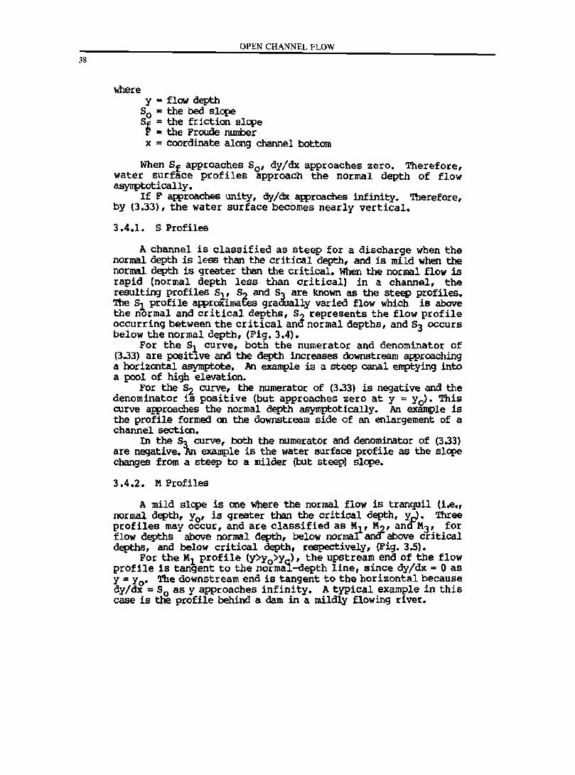
A mild slq.e is one where the normal flow is tranquil (i.e., normal depth, Yo' is greater than the critioal depth, y,.J. Three profiles may occur, and are classified as loll' M-2' anaM3 , for flow depths above normal depth, below normal anOiabove critical depths, and below critical depth, respectively, (Fig. 3.5).
For the Hl profile (y>yo>y ), the upstream end of the flow prOfile is tangent to the normal-depth line, since dy/dK - 0 as y = Yo' 'rile downstream end is tangent to the horizontal because dy/dX = So as y approaches infinity. A typical example in this case is the profile behind a darn in a mildly flowing river.
OPEN CHANNEL FLOW
39
Fig. 3.4. Gradually varied flow profiles for sleep slopes.
dy/dll' +
Fig. 3.5. Gradually varied }low profiles for mild sfopes.
40
OPEN CHANNEL FLOW
For the M2 profile (Yo>y>Yc)' the upstream end of the flow profile is tangent to the norma~ depth line, since dy/dx = 0 as y .. Yo' The downstream end of the flow profile is less than the normal depth but above (or equal t~ the critical depth. A typical exaJl{)le of this profile occurs at the upstream side of a sudden enlargement of a mild channel cross-section.
For the M3 profile (y<yc<yo)' the upstream flow depth is modeled to begin as an acute angle. The downstream flow terminates with a hydraulic jump. 'DIe most upstream flow depth is modeled as y = 0, and has an associated infinite flow velocity. The typical example of this profile is when a supercritical flow enters a mild channel.
3.4.3. C Profiles
When the normal depth and the critical depth are equal, the profiles resulting from this are labeled Cl.. and c3• C1 occurs when the flow depth is above the critical <lepth, and CJ occurs when the flow depth is below the critical depth. These profiles represent the transition conditions between M (mild) and S (steEp) flow profiles. 'lbe C-.2 profile is usually associated to the case of uniform critical flOW, (Fig. 3.6).
3.4.4. 'DIe Standard Step Method
Gradually varied flow profiles are generally computed by using any of three popular methods. Namely, the graphicalintegration method, the direct-integration method, and the standard step method. The standard step method continues to be the most commonly used.
In the standard step method, the computation of the flow depth is carried out on a station to station basiS where the hydraulic characteristics are known. The computation procedure is a trial and error method to balance the energy ecplticn.
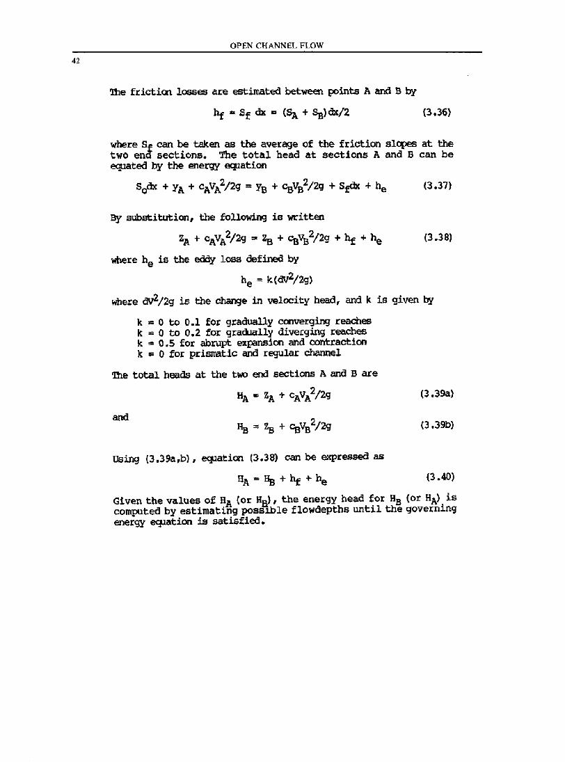
For convenience, the position of the water surface is measured with respect to a horizontal datum. The water surface elevations above the datum at the two end sections can be expressed (as is also shown in Figure 3.7)
(3.34)
and
(3.35)
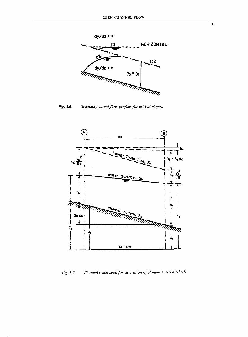
Fig. 3.6.
OPEN CHANNEL FLOW
dy/dll" +
_ ""","_ CI r .......... 0-C~ ::;;r
'~d •• +
-----
-0-Yo· )b
HORIZONTAL
Gradually varied flow profiles for critical slopes.
z.
1~ !~ ~
I J DATUM _ --'- _~--.-.L--l..-J-
Fig. 3.7. Channel reach used for derivation of standard step method.
41
42
OPEN CHANNEL FLOW
111e friction losses are estimated between points A and B by
(3.36)
where Sf can be taken as the average of the friction slq>es at the two end sections. The total head at sections A and B can be e<pated by the energy ecpation
Sodx + YA + cAVA2/ 29 = YB + CsVB2/29 + stdX + he (3.37)
By substitution, the following is written
zA + cAVA2;2g .. 2a + CsvB2/2g + ht + he
where he is the eddy loss defined by
he = k(dV2/2g)
(3.38l
where dV2/2g is the change in velocity head, and k is given by
k ,. 0 to 0.1 for gradually converging reaches k .. 0 to 0.2 for gracllally diverging reaches k ,. 0.5 for abrupt expansion and contraction k .. 0 for pri5llatic and regular channel
111e total heads at the tlllO end sections A ana B are
HA .. ZA + cAVA2/ 2g
and
Using (3.39a,b), equation (3.38) can be expressed as
HA=IIs+bt+ he
(3.39a)
(3.39b)
(3.40)
Given the values of HA (or Hal, the energy head for FIB (or HAl is computed by estimating posslble flowdepths until the governing energy e<pation is satisfied.
CHAPTER FOUR
HYDRAULIC ELEMENTS
4.1. Introduction
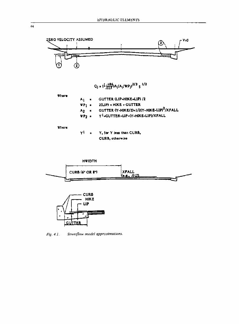
In this chapter, several complete computer programs will be presented which provide the computer capability of solving for the various channel flow dimensions associated with the normal depth. Because it is preferable to link together all of the programs presented in this chapter, PROGRAM 1 provides a MAIN MENU title page wherefrom the user may select the desired computational routine. For normal depth flow in prismatic channels, PROGRAM 2 solves for anyone of the variables: channel base, channel side slope or z-factor, flow depth, or flow rate given the remaining variables. Also included in ProGRAM 2 is the analysis of critical depth flow variables. Pipeflow normal and critical depth flow analysis is provided in PROGRAM 3. PROGRAM 4 provides for the normal depth flow analysis of a symmetrical roadway section. The program user enters values for the street halfwidth (the street section is assumed to be symmetrical about the roadway centerline), and dimensions of the gutter including curb depth, gutter lip and gutter hike (see Fig. 4.1). Given the specified flow r(lte, the streetflow analysiS considers both symmetrical flow and split flow effects using Manning's equation with a friction factor set at n = 0.015.
A powecful analysis routine for the study of open channel pipeflow effects through a junction structure is provided by PBOGRAM 5. Given an upstream and downstream pipe section, one or two lateral drains into the junction, the drop in elevation through the junction, flow rates and friction factors for each pipeline, and assumed hydraulic controls, ProGRAM 5 analyzes the junction hydraulics for the determination of the probable hydraulic control and then computes the appropriate upstream and downstream pipeline flow depths. The method of analysis used is based on a simple balance of steady flow specific force which relates the change in UGL to the pressure plus momentum variation through the junction with minor losses ignored. The program uses an iterative procedure to balance the pressure plus momentum relationships.
pflDGRAM 6 provides the computer capability for the analysis of gradually varied flow in regular trapezoidal channels. Similarly, PROGRAM 7 provides for the analysis of gradually varied flow in pipelines. Consequently, the complete water surface
43
44
ZERO VELOCITY ASSUMED I
Where
Where
yl •
HYDRAULIC ELEMENTS
,.,. (I ·~")A'(A'/VIP.)21J 5 1/1 ... " -.0lJ" " ,
GUTTER. (LIP+HIKE+LlP) 12 2(LIP) + HIK E • CUTTER
GUTTER (Y-HIKElZ)+1/2(Y-HIKE-LlP,Z/XFALL
Y l.c:;UTnR+UP+(Y -HIKE-LIPIIXFALL
Y, lor Y le51 than CURB,
CURB,otherwjse
HWIOTH
! CURB ('" OR I") I XFALL
----____ ~~================~(e~.I~ .. =.~O~IZ~I============ ______ ~ c::J
(/[lCURB
HIKE
L r--\ • • . .
I • . • . CL TTI!R
Fig. 4.1. Streetflow model approximations.
HYDRAULIC ELEMENTS
profile for pipeline storm drains can be developed by using PROGRAMS 5 and 7, with the program user determining the location and length of hydraulic jumps where appropriate.
4.2. l'BOGIWI 1. Hydraulic Elenents Main Menu
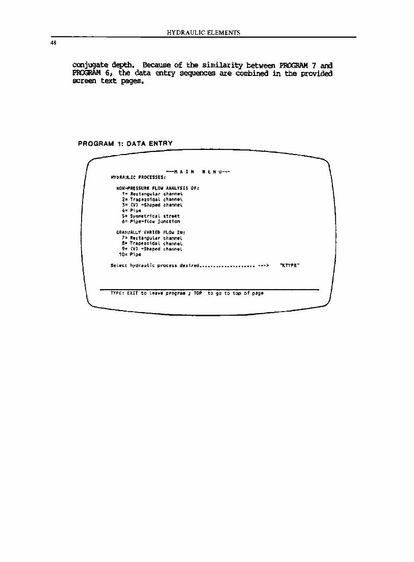
'!he necessary software and data entry sequence to formulate a package program is presented. The utility of this program is that PROGRAM 2 through PROGRAM 7 are combined into a single program system. The text page shown for the data entry of PROGRAM 1 provides an example of how to set up a user-friendly environment for the program user.
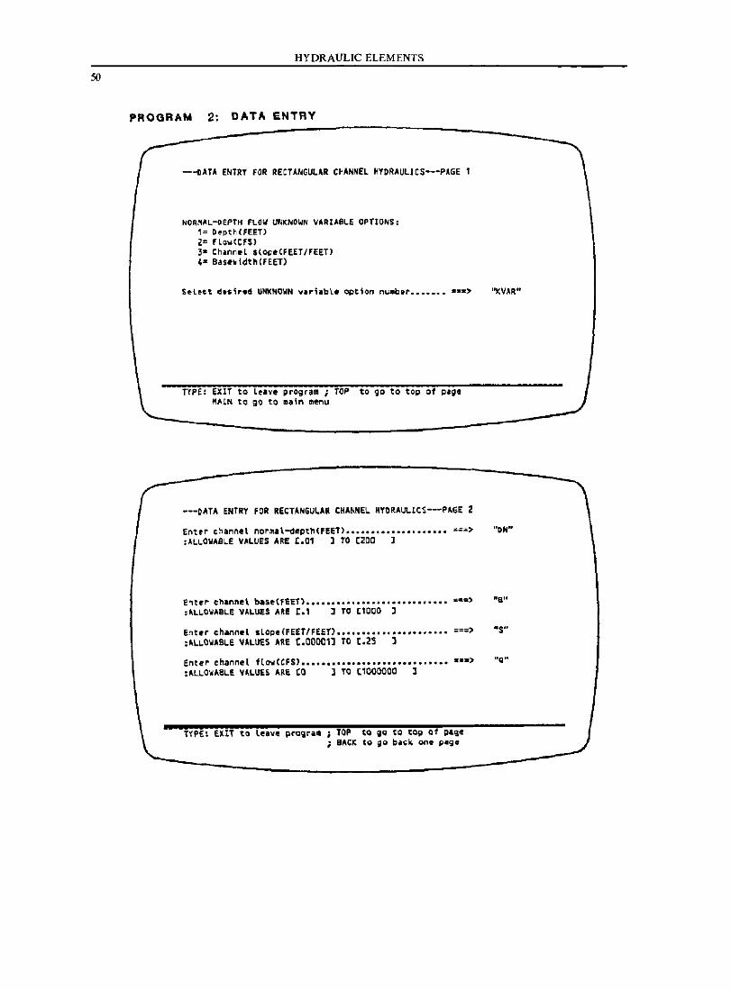
4.3. PRJGRJ\M 2. Channel Hydraulic Elements
Normal depth flow in regular open channels can be analyzed by use of Manning's equation
(4.1)
where Q " flowrate, in cfs A " area of flow, in square feet R " flow area divided by the wetted perimeter Sf " friction slC{le (or, for normal depth, the channel slope) n ~ friction factor
An unknown value for one of the variables used in Eq. (4J.) can be estimated by use of PROGRAM 2. The computer code is arranged for estimating the selected unknown variable by means of an iteration procedure until the unknown value is within a programmed tolerance of satisfying Manning's equation. Also included in the program is the computation of critical depth hydraulic information corresponding to the normal depth flow computed in Eq. (4J.).
4.4. PRJGRJ\M 3. Pipeflow Hydraulic Elements
Normal depth and critical depth estimation for pipeflow is provided by PROGRAM 3. Also included is the estimation of pipe capacity flows, friction slopes, and the computation of other hydraulic factOl::s such as specific energy, Froude number, pressure plus momentum, and flow velocity. The normal depth estimates correspond to the smallest possible value when flow depths exceed 0.82 of the pipe diameter.
4.5. PROORlIM 4. Streetflow Hydraulic Elements
The analysis of streetflow is a commonly occurring problem in civil engineering design. In this program, the engineer can analyze the speCial case of capacity flow on one side of the
45
HYDRAULIC ELEMENTS
street section with the remaining flows occurring on the other side of the street. The streetflow hydraulics are analyzed by using Manning's equation for normal depth flow. The street section is subdivided into two subreaches where one channel spans from the street centerline to the edge of the street gutter, and the second channel spans from the edge of the gutter to the inside edge of the street curb. lUI flows outside of the street curb are .assumed to be in a ponded condition with a negligible contribution to the total flow capacity of the system, (see Fig. 4.1).
The street section is assumed to be symmetr ical about the street centerline; consequently, data entry corresponds to both sides of the street section. The engineer ente~s the street curb height, gutter wioth, gutter hi~e (rise in elevation along the gutter width), gutter lip (difference in elevation between roadway section and top of gutter), street half width, and roadway crossfali (slope of the pavement to the gutter). Given a flowrate, p~ 4 computes the normal depth flow hydraulics for either the case of symmetrical streetflow or split flow.
4.6. P~ 5. Pipeflow Junction Analysis
A difficult problem which occurs in pipeflow hydraulics is the analysis of a junction where open channel flow effects need to be considered. p~ 5 provides the computer capability to estimate the hydraulic control at the junction and the corresponding flow depths at the ilownstream and upstream points of the junction.
The analysis of the junction hydraulics is by means of a simple balance of specific force which relates pipeflow pressure plus momentum to the change in the hydraulic grade line through the junction. In the case of open channel flow, however, the hydraulic parameters of flow depth, flow area, velocity, pressure plus momentum, and friction slope are all computational variables. In oroer to achieve a pressure plus momentum balance, an iterative pcocedure is used which sequentially halves the differences in flow depth until a balance is achieved.
An examination of the computer coOe reveals that several tests are performed in order to estimate the probable hydraulic control. For example, the pressure plus momentum function is usee to oetermine whether a hydraulic jump occurs at or near the junction, or whether sufficient momentum exists in the junction inflows to wash the hydraulic jump downstream. lIdditionally, it is noted that minor losses are ignored in the balance of pressure plus momentum. However, the computer coOe can be modified to include other energy losses. The engineer enters oata values of pipesizes, friction factors, pipe slopes, drop in elevation through the junction structure, angle of approach with respect to the downstream mainline pipe, flowrates, and estimates of the downstream and upstream flow depths, (see example). The program considers the ente~ed flowdepths in the computation of the
HYDRAULIC ELEMENTS
hydraulic control. Should computed flowdepths exceed 0.82 of the pipe diameter, then the program terminates and notifies the program user to consider a pressure flow analysis. Downstream pressure flow conditions may be considered in the program by entering the difference between the downstream pipe flowline and the assumed HGL as the downstream flowdepth. This type of analysis may be important in cases where sufficient inflow pressure plus momentum may force a hydraulic jump downstream of the junction structure.
4.7. ProGRAM 6. Gradually Var ied Flow in Open Channels
The calculation of backwater curves, drawdown curves, and other gradually varied flow profiles is an important analysis problem in open channel flow hydraulics. PROGRAM 6 provides a computer capability for the estimation of such water surface profiles for the case of rectangular, trapezoidal, and V-shaped channels. The program determines the normal and Critical depth, the hydraulic control, the governing water surface profile classification, and then computes the water surface profile. Flow depth, velocity, specific energy, and pressure plus momentum are included in the computation results. The program computes the specific energy difference between normal depth and critical depth; this available energy is then divided by the number of increments speCified by the program user. Using the resulting increment of available specific energy, the water surface profile is computed according to the balance of the energy equation.
4.8. PROORAM 7. Gradually Varied Flow in Pipelines
Similar to PROGRAM 6, this program provides the computer capability for the analysis of gradually varied flow in pipelines. Included in the program results are the determination of normal and critical depths, the hydraulic control, water surface profile, specific energy, pressure plus momentum, and flow depths.
It is noted that a combination of PROGRAMS 5 and 7 provides a complete computer capability for the analysis of open channel flow hydraulics in pipelines. However, the determination of the location and length of hydraulic jumps is not included in the programming. Rather, this type of information is currently indeterminate and is left to the engineer for special consideration on a case by case basis. A common approach is to assume the jump to occur as a shock whereby the conjugate depths are matched at a single paint, with the length of the jump being assumed as zero. This type of solution may be unacceptable in cases where a pipe lateral enters the main channel immediately upstream of such an assumed hydraulic jump shock, and the hydraulic control for the pipeline is assumed to be the lower
47
4S
HYDRAULIC ELEMENTS
conjugate depth. Because of the similarity between PBOGRAM 7 ard PROORAM 6, the data entry sequences are combined in the provided screen text pages.
PROGRAIvI 1: DATA ENTRY
---M A 1 N "E N U--HYD.A~lC PROCESSES:
NON-PRESSURI FLOW ANALYSIS Of: 1= R~ctangYl'r ;hanneL 2- Tra~el0id'l ehannel 3= ev) -Shap.d channel 4'" PilJ_ S. Symm@tric,l street 6= Pipe-flow junction
GRADUALLV VARI£D FLOW IN: 7= Rectangul.r channel 8- Trapezoidal ehannel 9,. (V) -Shaped channel
'0= Pip.
Select hydraulic process desired •••••••••••••••••••• ;;~>
TYPE: EXIT to le.~. ~rogra. ; TOP to go to top of page
c
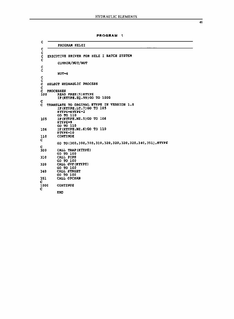
c c
PROGRAM BELEI
HYDRAULIC ELEMENTS
PROGRAM 1
C EXECUTIVE DRIVER FOR BELE I BATCH SYSTEM C
C C
C C
COMMON/NOT/NUT
C SELECT HYDRAULIC PROCESS C C PROCESSES 100 READ FREE(S)KTYPE
IF(K'1'YPE.EQ.99)GO '1'0 1000 C C ~NSLATE TO ORGINAL lTYPE IN VERSION 1.0
IP(KTYPE.LT.7)GO'1'0 lOS KTYU-KTYPE-2 GO TO 110
105 IP(KTYPE.NE.5)GO TO 106 K'l'YPE-' GO TO 110
106 IP(KTYPE.NE.6)GO TO 110 K'l'YPE-IO
110 CONTINUE C
GO TO(300.300.300.310.32D,320,320,32D,340,351).K'l'YP£ C 300 CALL TRAP(KTYPE)
GO TO 100 310 CALL PIPE
GO TO 100 320 CALL GVF (KTYPE)
GO TO 100 340 CALL STREET
GO TO 100 351 CALL OPCBlIN C 1000 CONTINUE C
END
49
50
HYDRAULIC ELEMENTS
PROGRAM 2: DATA ENTRY
--DATA ENTRY FOR RECTANGULAR C~ANNEL HYDRAULICS--.p.GE 1
NORMAL-OEPTH FLOW UNKNOWN VARIASLE OPTIONS: 1= DepthCFEETl 2= f'Low(CFU Ja ChanneL sl~.(FEET/FEET' 4- 9ase~idth(FEET)
TYPE: EXIT to leave ~rogram ; TOP to go to top of ~Ig. MAIN to go to ma;n menu
---DATA ENTRY FOR RECT,NGULAR CKANNE, KYO •• UCICS--PAGE 2
"KVAR"
Enttr channel nortlllll-depthCfEE"T) •••• o.o ••••••••••••• "'==> "DN" :~LLOWASle VALUES ARE C.01 ] TO (200 ]
Entrt" channel bast(f!:T) •••••••••••••••••••••••••••• =OJ=) "Btl :"L\..CWASL.E VALUES ARE [.1 1 TO [1000 ]
Ent,r channel slope(FE£T/,:EET) •••••••••••••••• u ..... ===> "s" :'~OWAB,E VALUES ARE C.OO~l] TO (.25 ]
Enter channel flo'olCCFS} ••••••••••••••••••••••••••••• _=a) "g" :AU .. <lWABLE ~M.U£S ARE to J TO ['000000 l
TYPE: EXIT to Leave prQ~ril!l TOP to iQ {Q tQg of g.aCSe BACK tg ~o b.~k one ~age
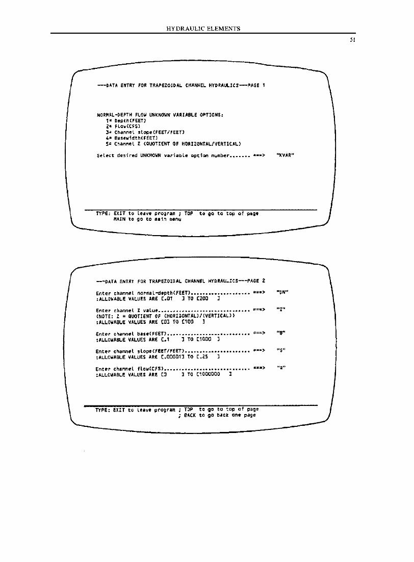
HYDRAULIC ELEMENTS
--OA.TA ENTRY fOR TRAPeZ01DAL. CHANNEL. HYDRAULICS-PAGE 1
NORMAL-DEPTH FLOW UNKNOWN VARIABLE OPTIONS: 1= fleQthCFEET) Z .. Flcw<CF$) 3- ChanneL slo~.(FEET/FEET) ,_ Saslwidth(FEET) 5: Co'nMel l (QUOTIENT OF HORIZONTAL/VERTICAL)
s~lect de~ired UNKNOYN variable option number ••••••• =~.>
TYPE: EXIT to Ltave Qro~ram ; TOP to ga to tap of pag. MAIN to go to ~ain menu
---DATA ENTRY fOR TRAPEZOIDAL CHANNeL. HYDRAU~ICS---PAGE Z
"KVAR"
Enter channeL normal-de~th(FE.eT) •••••••••••••• ....... :1=.> NON" :ALLOWABLE VALUES ARE [.01 ] TO [200 J
Enter ehannet Z valu ....... eO ...................................... ===> "z" (NOTE: Z = QUOTIENT OF (HORllONTALl/(VERTICALl) :ALLOWABLE VALUES ARE tOl TO tl00 l
Ente,. channlltl base(FEET) ............................................... ::::==> ·'S" :A~~OWABLE VA~UES ARE t.1 l TO tl000 J
Enter chaM.l slope(FEET/FEET) •••••••••••••••••••••• ~~=> US" :ALLOWABLE VALUES ARE C.00001] fO [.25 l
Enter cnannel floweCFS) .............................. ::1==> "a" :ALLOWAaL~ VALUES AR! [0 1 fa C1000000 1
TYPE: EXIT to le.ve prcgram ; TOP to go to to~ of page ; BACK to go back one page
51
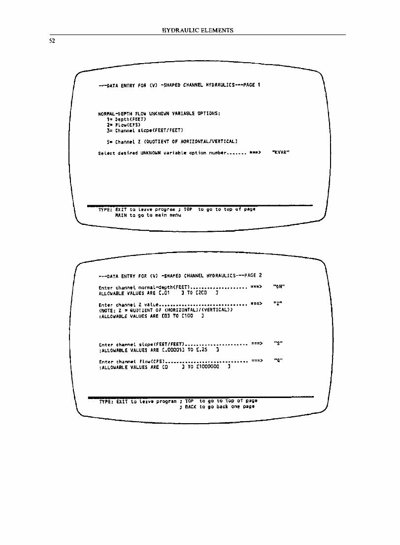
52
HYDRAULIC ELEMENTS
---DATA ENTRY FOR (V) -SHAPED CHANNEL HYDRAULICS---PAGE 1
NOR"AL~EPTH FLOW UNKNOWN VARIABLE OPTIONS: 1= Oepth(FEe:T) 2= FLo'lllCCP$) 3= ChanneL slcpe(FEer/FEET)
5- Channel Z (QUOTIE~T OF HORIZONTAL/VERTICAL)
TYPE: EXl1 to leave program ; TOP to go to top 01 p.ge MAIN to ga to main mtn~
---DATA ENTRY FOR (~) -SHAPED CHANNEL HYORAULICS---PAGE 2
"K.VA-R"
Enter cnanne!. normaL-dept.h(fEET) I ....................... ===> "nN" ALLOWABLE VALUES ARE [.01 l TO C200 l
Enter channel Z vaLue ••••••••••••••••••••••••••••••• ===> HZ" (NOTE: Z = QUOTIENT OF (HORIIONTALJ/(VERTICAL» :ALLOWABLE VALUES ARE [0] TO [100 l
Entel" cha""e-l slope(FEET/FEET' ........................ ===> "s" :ALLOWABLE VALUES ARE [.coaCt) TO t.25 ]
Ente,. I:hann~l flcMlCCfS) ••••••••••••••••••••••• • •• ••• ===> "Q" :ALLOWASLE VALUES ARE (0 l TO [1000000 1
TlPE: eXIT to tofiliV. program TOP to 90 10 19p of piglt ; BACK to go back one page
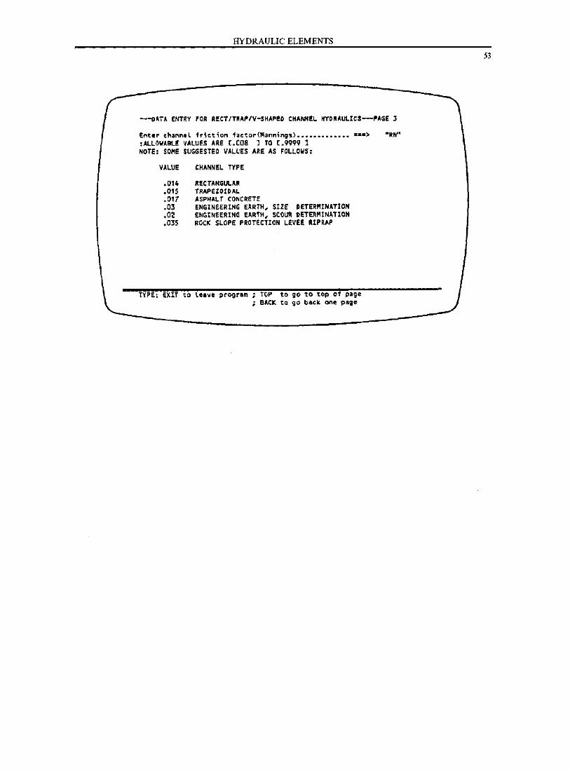
HYDRAULIC ELEMENTS
---oATA eNTRY FOR RECT/TRAP/V-$HAPEO CHANHE~ HYDRAULIC$---PAGE 3
Ent.r thannll fric.tion factor(ft1af'lnings) ................ ===) "RH" :ALLOWABlE VALUES ARE [.coa 1 TO [.9999 1 NOTE: SOME SUGGESTED VALUES ARE AS FOLLOWS:
VALUE
.014
.015
.017
.03
.02
.035
CHANNEL TYPE
R£CTANGUL.Afil TRAPEZOIDAL ASPHALT CONCRETE ENGINeERING EARTH. SIZE DETERMINATION ENGINEERING EARTH. SCOUR DETERMINATION ROCK SLOPE PROTECTION LEVEE RIP RAP
TYPE; eXIT to leave program; TOP to go to ~op of page ; BACK to go back one paie
53
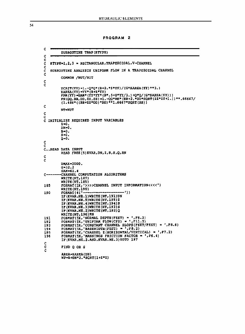
54
c
c c
HYDRAULIC ELEMENTS
PROGRAM 2
SUIIROtlTINE TaAP (~TYPE)
C KTYPE-1,2,3 - RECTANGULAR,TaAPEZOIOAL,V-CHANNEL C C SUBROUTINE ANALYSIS UNIFORM FLOW IN A TRAPEZOIDAL CHANNEL C
C C
C
c c
COMMON /NUT/NUT
YCRIT(YYj-l.-Q*Q* (B+2.*Z*YY)/(G*XAREA(YY) **3.) XAR&A(YY) -YY' (B+1*YY) FPK(Y1j-GAM*(YY·YY*(B·.5+Z*Y1/3.)+Q*O/(G*XAREA(YY») PN(QQ,BB,00,ZZ,SS)-1.-QQ*RN*(BB+2.*00*SQRT(ZZ*ZZ+1.»**.66667/ (1.486*((B8+ZZ*00)*OD)**1.6667*SQRT(SS»
C INITlALlZE REQUIRED INPUT VARIABLES z-o.
C C
ON-O. 8-0. s-o. 0-0.
C •• READ DATA INPUT
c c
READ rREE(5)KVAR,DN,z,B,S,Q,RN
DIWt-2000. G-32.2 GAM-52. 4
C-------CHANNEL CORPUTATION ALGORITHMS WRITE (NT,187) WRlTE (NT, 185)
185 FORMATCIX,'»»CBANNEL INPUT INFORMATION««') WR1TE(NT,190)
190 FORMATC4C'--------'» IF (KVAR.NE.1)WRITE(NT,191)DN IP(KVAR.NB.S)WRIT£(NT,195)Z IF(KVAR.NB.4)WRITE(NT,194)S IP(KVAR.NB.3)WRITE(NT,193)S IP(KVAR.NE.2)WRITE(NT,192)Q WRITE (NT,U6)RN
191 FORMAT (SX, 'NORMAL DEPTH(FEET) - ',PS.2) 192 PORMAT(5X,'UNIFORM PLaN(CFS) - ',Fll.2) 193 FORMAT(5X,'CONSTANT CHANNEL SLOPE (FEET/FEETI = ',F8.6) 194 FOaMAT(5X,'BASEWIDTH(PEET) - ',P8.2) 195 FORMAT(5X, 'CHANNEL Z(HORIZONTAL/VERTICAL) - ',F1.2) 196 FORMAT(5X,'MANNINGS FRICTION FACTOR - ',F6.4)
IF(KVAR.NE.2.AND.KVAR.NE.3)GOTO 197 c C FIND Q OR S C
AREA-KAR&A(DNI WP-B+DN*2.*SQRT(1+Z*Z)
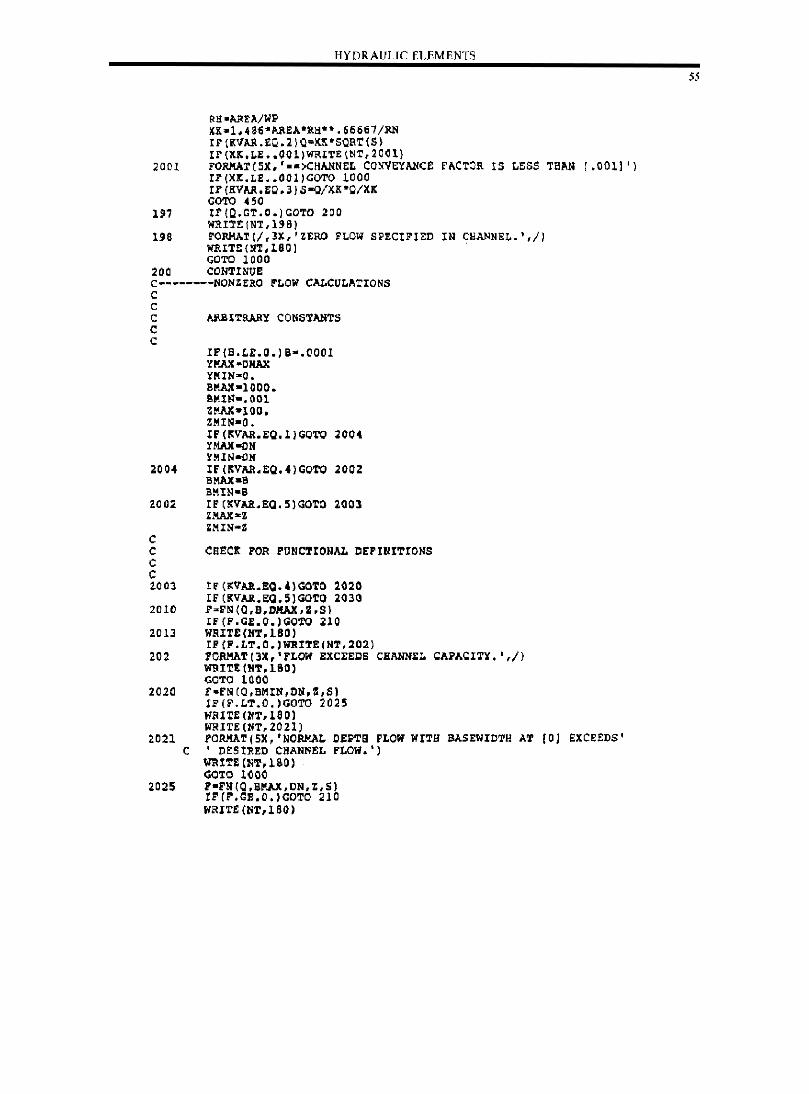
HYDRAULIC E],EMENTS
RaoAl<EA/IiP XX·1.4e~·AaEA"Ra"" •• 6661/RN rF(KVkR.£Q.2jQ=KK"SQRT(S) Ir(X~.~E •• 001)WRI~E(~T,20~lj
2001 FORMAT(SX"")CHANNEL CONVEYANCe fACTOR IS LESS TSAD [.001] 'j Ir(Xx.~E •• OOl)GOTO 1000 Ir(RVAR.EO.3j5-o/xK"O/X~ GOTO 450
1~7 tFtO.GT.C.jGOTD 200 WJ\IT~(NT,UB)
198 rORMAT(/,lX,'ZERO FLOW SPECIFIED IN CEANNEL.',/) WRIT!: (NT, no j GOTO 1000
200 CONTINUE C~"~-----NONZERO FLail CALCULATIONS c C C ARBI~RARY CONSTANTS C C
~OO4
2002
C C C C ~OO3
2010
2013
202
2020
2021 C
2025
IF{S.LE.O.)S-.OOOI YMAlI-DKAX X'MIN-O. SMAll-I 000. eMIN-.ODl ZMAX·1IJD. ZI!IN-O. If{~VAR.EQ.I1GO~O 2004 YMAX-ON YMIN-ON If(RVAR.£Q.4)GOTO 20DZ BMAX-a BMIN-a IF(KVAR.EQ.S)GO~O 200l ZMAX,2:Z ZMIN"'Z
CSEcr rOR PUNC!IONAL DEFINITIONS
IF (KVAa.!Q.')GOTO ~020 IE(KVAR.~Q.5)GOTO 203Q r-F~tO.9.DKAX,Z.S) IF{F.GE.O.lGOTO ~lO WRITE(IfT,L80l IP{P.LT.O.)WRITE(NT.202) rORMATI3X,'FLOW EXCEEgS CHANNE~ CAPACITY. ',I) mUTt(IIT,180) GOTO lOOO r-FN(O,BMtN,DN.S,S) IF(F.LT.O.lCOTO 2025 IIIU1:£(IfT.LSOl WIHTE(NT,2021) rORMATt5X,'NORMAL OEPTB FLOII IIITa BASEWIDTH AT rOJ EXCEEDS' , DeSIRED CHANNEL FLOW.')
mUTE (IIT,lSO) GOTO lOOO '-FN(Q,BKAX,DN,t,S} IF(r.GE.O.)GOTO 210 IIRIrE (NT,160)
55
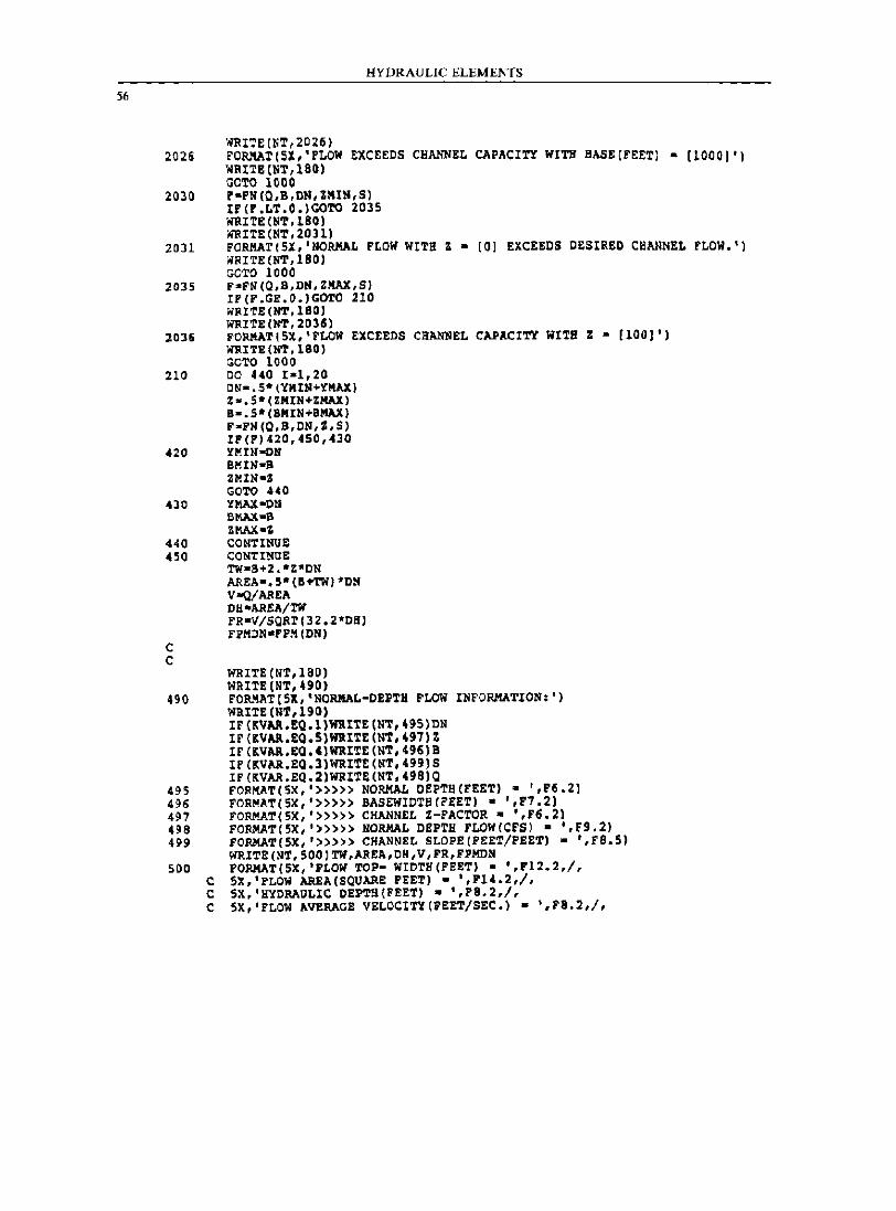
56
HYDRAULIC ELEMENTS
'NRI':'E(NT,202ti) 2025 rORMAT(SX,'FLOW EXCEEDS CHANNEL CAPACITY WITH 8AS~(rEETI - [10001')
WRITE (NT,180) aoTO 1000
2030 r·FH(O,B,DN,ZMIN,S) IF(P.LT.O.)GOTO 2035 'NRITE(NT,180) IiRITE(NT,2011)
2031 FORMAT (SX, 'NORMAL FLOW WITH Z • (01 EXCEEDS DESIRED CHANNEL FLOW.') WRITE(NT,180) GOTO 1000
2035 FoFN(Q,B,DN,ZMAX,S) IP(F.GE.O.)GOTO 210 li'RITE(NT,180J WRITE(NT,2035)
2036 FORMAT(5X,'FLOW EXCEEDS CHANNEL CAPACITY WITH Z - [lOOJ'J WRITE(NT,180J GOTO 1000
210 CO 440 r-l,20 CN-.S*(YMIN+YMAX) Zo.S*(ZMIN+ZMAX) a-.S*(BMIII+BMAX) FoFN(Q,B,OIl,I,S) IP(P)420,450,430
420 YMIN-OII BMIII-B ZMIN-' GOTO UO
430 YMAX-ON BMAX-B ZMAX,-Z
440 CONTINUE: 450 CONTINUE
C C
TW-S+2.*Z:·DN AREA-.5·(B+TW)-DN VoQ/AREA OH-AREA/TW FR-V/SQRT(32.2*OB) FPIIDN-FPII(ON)
WRITE (NT, 180J WRITE (NT, 490)
490 FO~~T(5X,'NORMAL-OEPTH FLOW INFORMATION:') WRITE (NT,190) IF (KVAR.EQ. l)WRITE (HT,495)DN IF(KVAA.EQ.5)WRITE(NT,497)Z IF (KVAA.EQ.4)WRITE(NT,496)B IF (KVAR.EQ.3)WRIT!(NT,499)S IF (KVAR.EQ.2)WRIT!(NT, 498)0
495 FORIlAT(5X,'»») NORMAL DEPTH(F!ET) a ',F6.2) 496 FORIlAT(5X,'»») BASEWIOTS(FEET) • ',F7.2) 497 FORI!AT(5X,'»») CHANNEL Z-FACTOR - ',F6.2) 498 FORI!AT(5X,'»») NORI!AL DEPTH FLOW (CFS) • ',F9.2) 499 FORI!AT(5X,'»») CHANNEL SLOPE(FEET/FEET) • ',FS.5)
WRITE(NT,500)TW,AREA,OH,V,FR,FPIIDN 500 FORMAT (SX, 'FLOW TOP- WIDTH(FEET) • ',F12.2,/,
c 5X,'FLOW AREA(SQVARE FEET) - ',F14.2,/, C 5X,'HYDRAULIC DEPTH(FEET) - ',F8.2,/, C 5X,'FLOW AVERACE VELOCtTY(FEET/SEC.) - ',F8.2,/,
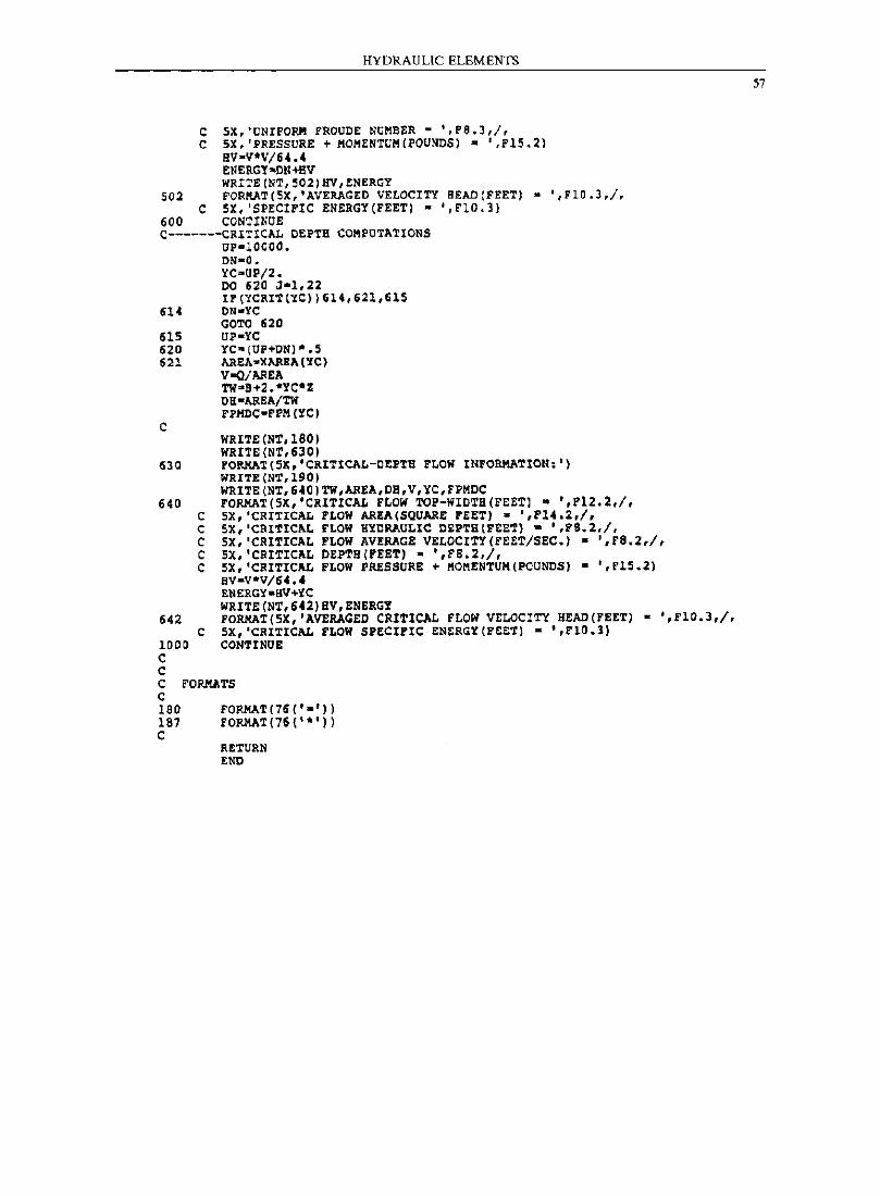
HYDRAULIC ELEMENTS
C 5X,'ONIPORM FROUDE NCMBER ~ ',Fe.3,1, C 5X, 'PRESSURE + ltOMENTUII(POUNDS) - ',FlS.2)
HV-V·V/64.4 ENERGY-CN+BV WRITE(NT,~02)BV,ENERGY
502 FORMAT(5X,'AVERAGED VELOCITY BEAD (FEET) - ',FlO.3,/, C SX, 'SPECIFIC ENERGY(FEET) - ',F10.3)
600 CONTINuE c-------CRITICAL DEPTH COMPOTATIONS
OP-IOOOO. DN-O-. "iC-UP/2. 00 620 J-l,22 IF(YCRIT(YC»)614,621,61S
614 DN-YC GOTO 620
615 UP-YC 620 YC-(UP+DN)·.5 621 AREA-XAREA(YC)
C
630
640
642
1000 C C
C C C C C
C
V-<l/AREA TW"S+2. *YC·Z DII-A!<EA/TW FPltDC-PPM(YC)
WRITE(NT,lSO) WRITE (NT,630) FOIUlAT (SX, 'CRITlCAIo-OEPTH "LOW INFORMATION;') WRITE(NT,190) WRITE (NT, 640)TW,AREA,DH,V,YC, FPMDC FORMAT(SX,'CRITICAt. FLOW TOP-WIDTH(FEETl - ',FI2.2,/, 5X,'CRITICAL FLOW A!<~A(SOUARE FEET) • ',Fl4.2,/, SX,'CRITICAL FLOW HYDRAULIC CEPTH(FEET) • ',F8.2,/, 5X,'CRITICAL FLOW AVERAGE VELOCITY(FEET/SEC.) - ',FB.2,/, 51, 'CRITICAL DEPTH(FEET) - ',PB.2,/, 5X,'CRITICAt. FLOW PRESSURE + MOIIENTUlt(PQUNOS) • ',r1S.~) BV·V*V/64.4 ENERGY.av+YC WRITE (NT,642) HV,ENERGY FORMAT(5X,'AVERAGED CRITICAL FLOW VELOCITY HEAD(rEET) - ',rlG.3,/, SX,'CRITICAL FLOW SPECIFIC ENERGY(FEET) - ·,~lO.3) CONTINUE
C FORMATS C lao 181 C
FORMAT (76 ('.'») FORMAT(76("')
RETURN END
57
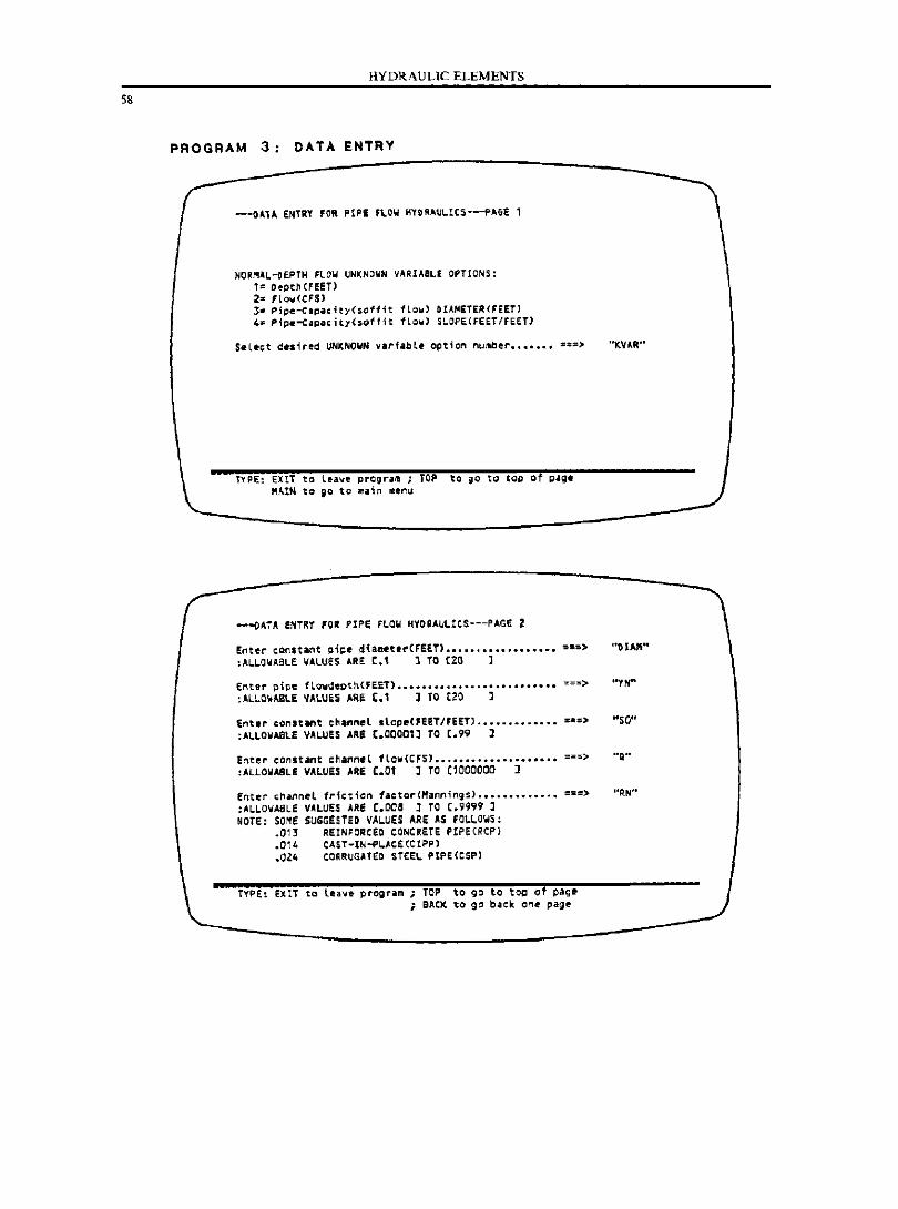
58
HYDRAULIC ELEMENTS
PROGRAM 3: DATA ENTRY
---OA1A EN1RY FOR PtPi FlOW HYOR~~~rCS---PAGe ,
NOR~.~-DEPTH flOW UNKNJWN vARIABLE OPTIONS: ,= O~~th (FEET) 2== Flow(CFS) 3- Pi~e-Capa(i~~(sot1;t flow) OIAMETER(FEETJ 4~ Pipe-Capacitl(50ffit f~ow) SLOPE(FEET/FEET)
TYPE: EXIT to lU'IIe J)rQOriilll ; TOP to ,,0 tQ cop of g.g. MAIN to iQ to ~~in menu
---oATA ENTRY fOR PIPE FLOW HYDQAULtCS---PAC£ 2
Enter cQnst&nt o;pe d;ameterCFEET) •••••••••••••••••• ;-=> ;ALLOWA8LE VALUES ARE C.1 1 TO (20 ]
Enter pipe flowdepth(FEST) •••••••••••••••••••••••••• ~::> :ALLO'ABL£ VAL~.$ AR£ t.1 1 TO tZO 1
"KV~R"
".,pro
(nUt' consunt e"a""el Ilopl!(FUT/FEETJ .............. =-=:> "SO" ;ALLOVAStE VALUES ARe t.COOC1J TO [.99 J
Ente,. c:onstilnt ~"a"n.~ flo ... '!;FS) ................... •• ="' .. > "Q"
:ALLOWABLE VALUES AR£ [.01 1 TO (1000000 1
Entlrr' ~/'I.a"nel fri~t1en facter{Hanning:s) .............. ===> "~N" :AL.1.0W'ABLf VALUES ARE (.008 .J TO C.99'79 J NOTE: 50'£ SUGGESTED VALUES ARe AS fOWL'.':
.013 REIN~O~CEO CONCRETE PIPECRCP)
.014 CAST"'lN-PL..J.CE(CIPP)
.OZ4 ca~RUGJTE~ STEEL PIPE(esP)
TYPE: EXIT to lea~~ program; TOP to go to tog of pagp ; BACK to go back o"'~ page
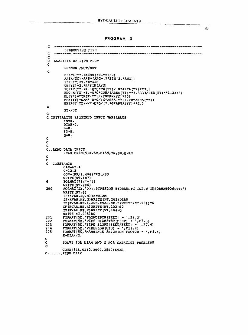
HYDRAULIC ELEMENTS
PROGRAM 3
c ---------------------------------------------------------------------SUBROUTINE UPE
c ---------------------------------------------------------------------C C ANALYSIS OF PIPE FLOW C
c
c
C
COIIMON /NUT/NUT
O£LTA(¥Y)~ACOSCC~-¥Y)/R) AREACYl)-R*P.*(ANG-.5*SIN(2.*ANG)) P£R(YY)-2.*P.*ANG TW(YYj-2.*R*SINCANGl YCRIT(YY)-1.-Q*0*TWCYl)/(G*AREACYY)·*3.) YNORK(YY)-1.-Q*O*CON/CAREA(YY)**3.3333/PER(lY)·*1.3333) DL(YY)-YCRIT(Yl)/(YNORK(YY)*SOj FPM(YY)-GAM*(O*Q/(G*AREA(YY))+YS*AREA(YY)) ENERGY(YY)·Yl+Q*Q/C2.*C*AREA(YY)·*2.)
C INITIALIZE RtOOIP.£D INPUT VARIABLES YN-a.
C C C
OIAl4"O. B""O .. SO-O. 0-0.
C •• READ DATA INPOT
c c
READ FREE(5)KVAR,OIAM,YN,SO,Q,RN
C CONSTAN'rS GAM-62.4 G-n.2 CON· (RN/l.486).*2./Sa WRITE (NT,187)
6 FORAAT(76 ('-')) WRITE (NT, 200)
200 FORAAT(lX,'»»PIPEFLOW HYDRAULIC INPUT INFORMATION««') WRl'l:E (NT, 6) IF (KVAR.EQ.4'YN-OIAM IF(KVAR.NB.3'WRITE(NT,202)DIAM IF(KVAR.NE.l.AND.KVAR.N£.3)WRITE(NT,201)YN IF (KVAR.NE.4'WRITE(NT,20J)SO IF(KVAR.NE.2)WRITE(NT,204)O WRITE (NT,20S)RN
201 FORAAT(SX,'FLOWDEPTR(PEET) - ',F7.3) 202 FORMAT(SX,'PIP£ DIAHETER(FEET) • ',F7.3) 203 FORMAT[SX,'PIP£ SLOPE[FEET/FEETl - ·,F7.4) 204 FORAAT [SK,' PlPEFLOW(CrS) • " F12. 2) 205 PORMAT[SX,'HANNINGS FRICTION FAC~OR - ',fS.ti)
R-OIAI!/2. C C SOLVE FOR DIAl! AND Q FOR CAPACI~Y PROBLEMS C
GOTO(Sll,SllO,lOOO,lSOO)lVAR C ••••••• FIND DIAM
59
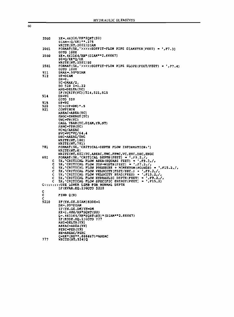
60
HYDRAULIC ELEMENTS
2000 XKa.46316/RN*SORT(SO) DIAK-IO/XK)**.375 WRITE(NT,2001)DIAK
2001 FORMAT(5X,'»»>SOFFIT-FLON PIPE CtAKETER(FEET) • ',F7.3) COW 1000
2500 XK-. 463164/RN* (CIAM**2.66667) SO-O/Xlt*O/XK WRITE(NT,2501)SO
2501 FORMAT(5X,'»»>SOFFIT-FLOW PIPE SLO?E(FEET/FEET) - ',F7.4) GOTO 1000
511 C!'\AX-.9S*DIAK 512 UP-DIAII
ON-O. YC~CMAX/2. CO 520 1-1,22 ANG-DELTA(YC) IP(YCRIT(YC)l514,521,515
514 ON-YC COTO 520
515 UP-YC 520 YC-(UP+DN) *.5 521 CONTINUE
AREAC -AREA IYC) tRGC-ENERGY (YC) TWC-TW(YCl CALL YBAR(YC,CIAM,YB,NT) FPMC-FPII (YC l "C-a/AREAC BYC-YC*VC/64.4 CHC-AREAC/'l:WC JoIRITE(NT,180) WRITE (NT, 781)
781 FORMAT(5X,'CRITlCAL-OEPTH FLOW INFORMATION.') JoIRITE(NT,6) WRITE (NT,601)YC,AREAC,TWC,FPMC,VC,HVC,OHC,ENGC
601 FORIIAT(5X, 'CRITICAL DEPTH(FEET) • ',F9.2,/, C 5X,'CRITICAL FLOW AREA (SQUARE FEET) • ',F9.3,/, C 5X,'CRITICAL FLOW TOP-WIDTH(FEET) - ',F7.3,/, C 5X,'CRITICAL FLOW PRESSURE + MOMENTUM(PQUNDS) • ·,F15.2,/, C 5X,'CRITICAL FLOW VELOCITY(FEET/SEC.) - ',F9.3,/, C 5X,'CRITICAL FLOW VELOCITY BEAC(FEET) - ',F15.2,/, C 5X,'CRITICAL FLOW HYDRAULIC DEPTH (FEET) • ',F9.2.1. C 5X,'CRITICAL FLOW SPECIFIC ENERGY(FEETI - ',F15.2)
C::::::::USE ~OWER LIMB FOR NORIIAL DEP~H IF(KVAR.EQ.l)GOTO 5220
c C C 5210
777
FIND Q (0)
IF (YN.GE.DIAMIKOOE-1 011". 99*OIAK IF{YN.GE.DK)YN-CK XK 3 1.486/RN*SQR1(SO) Q~.463164/RN·SORT(SO)·(DIAM·*2.6666i) IF(KOCE.EQ.l)GOTO 777 ANG-CELTA (YN) AREAC·AREA(YNI PERC-PER (YNI RS-AREAc/nRC O-XK*(RS**.666667)*AREAC WRITE (N'I', 534)Q
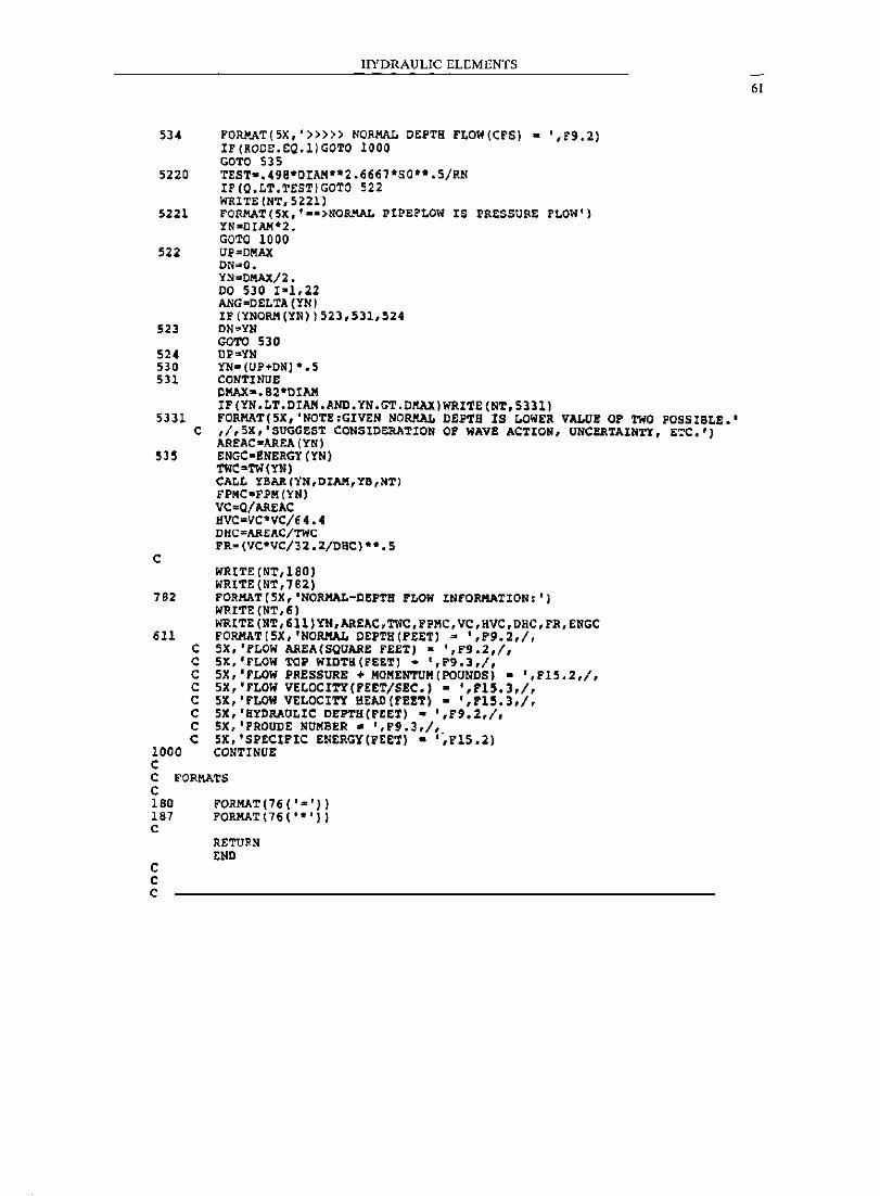
HYDRAULIC ELEMENTS
534 FORMAT(5X,'»»> NORMAL DEPTa FLOW(CFSI - ',r9,21 IF(KODE,EQ,1)GOTO 1000 GOTO 535
5220 TEST-.498*OIAM**2.6667*SO··.5/RN IF(O.LT.TEST)GOTO 522 WRITE(NT,5Z21)
5221 FORMAT(5X,'··>NORMAL PIPEFLOW IS PRESSURE FLOW') YN-OIAM*2 _ GOTO 1000
522 UP=DMAl( DN=O. YN-DMAX/2. 00 530 1-1,22 ANG=DELTA(YN) IF(YNORM(YN») 523,531,524
523 ON='iN GOTO 530
524 UP=YN 530 YN-(UP+ON) *.5 531 CONTINUE
OMAX-.82*DIM IF(YN.LT.DIM.AND.YN.GT.DMAX)WRITE(NT,S331)
5331 FORMAT(5X,'NOTE:GIVEN NORKAL DEPTH IS LOWER VALUE OF TWO POSSIBLE.' a ,I,SK,'SUGGEST CONSIDERATION OF WAVE ACTION, UNCERTAINTY, ETC.')
AREAC-AREA('iN) 535 ENGC-ENERGY(YN)
C
762
611
1000 C
c C C C C C C C
TWC-TW(YN) CALL YBAR(YN,DIAM,YD,NT) FPMC-FPII ('iN) VC=Q/AREAC BVC=VC'VC/6 4.4 DHC=AREAC/TWC FR-(VC*VC/32.2/DBC)**.5
WRITE (NT,1S0) WRITE (NT,782) FORHAT(5X,'NORMAL-DBPTH FLOW INFORMATION:') WRITE(NT,6) WRITE (NT,611)YN,AREAC,TWC,FPMC,VC,HVC,DHC,FR,ENGC FORHAT(SX,'NORIIAL DEPTH(FEETl s ',F9.2,I, SX,'FLOW AREA (SQUARE FEET) - ',r9.2,/, 5X,'FLOW TOP WIDTB(FEET) - ',F9.3,/, SX,'FLOW PRESSURE + MOIIENTUII(POUNDS) - ',FI5.2,/, SX,'FLOW VELOCITY(FEET/SEC.) - ',F15.3,I, SX,'rLOW VELOCITY HEAD[rE!T) - ',F15.3,I, 5X,'HYDRAULIC DEPTH(rEET) - ',F'.2,/, SX,IFROUDE NUMBER. I,P9.3,/, SK, 'SPECIFIC ENERGY(FEE"r) - '",F1S .2) CONTINOE
C FORMATS C 180 187 C
C C C
FORHAT(76('-')) FORHAT (76 ( '. 'll
RETURN END
61
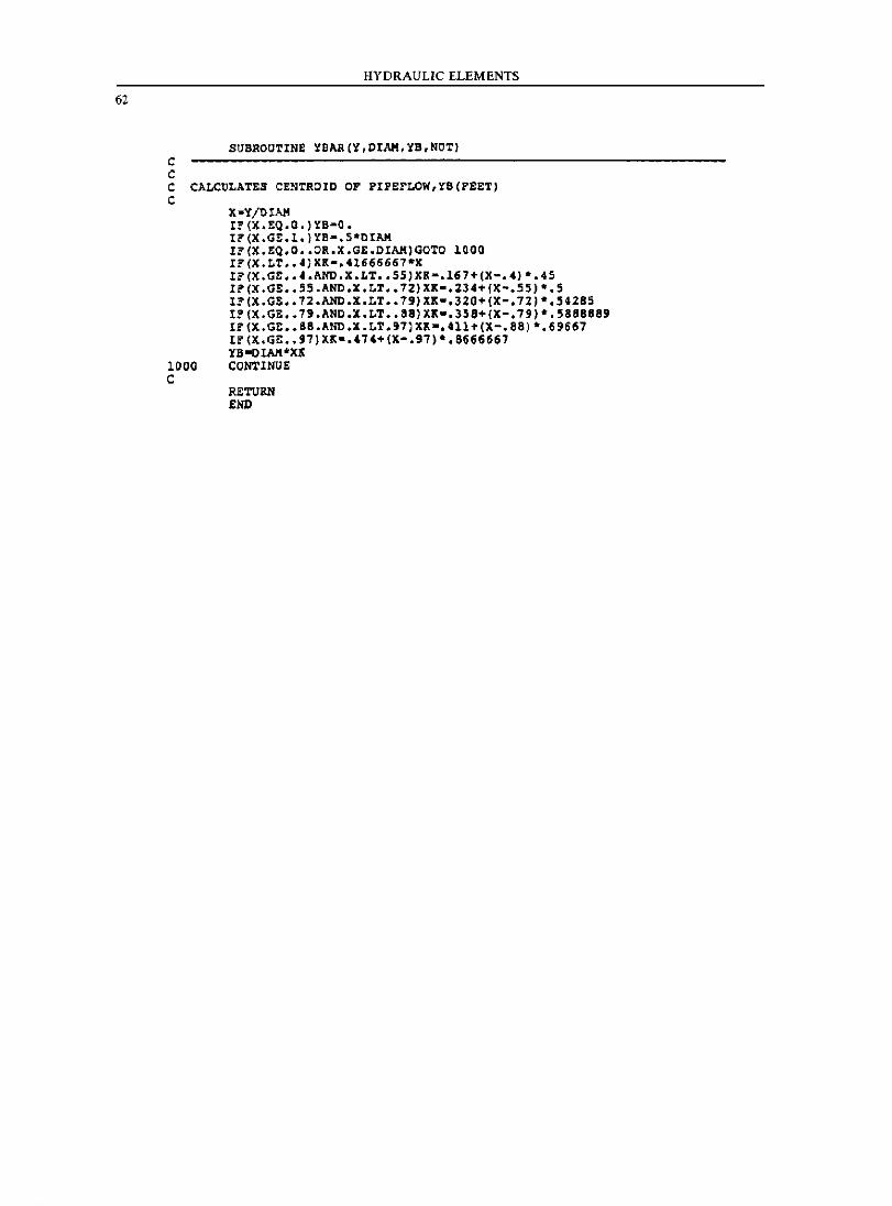
62
c c
HYDRAULIC ELEMENTS
SUBROUTINE YBAR(Y,DIAH,YB,NOT)
C CALCULATES CENTROID OF PIPEFLOW,lB(FEET) C
X-Y!DIAH IF(X.EQ.O.)lB-O. IF(X.GE.l.)lB-.S·DIAH IF(X.EQ.O •• OR.X.GE.DIAH)GOTO 1000 IF(X.LT •• 4)XK-.41666667·X IF(X.GE •• 4.AND.X.LT •• SS,XK-.167+(X-.4)·.4S IF(X.GE •• SS.AND.X.LT •• 72)XK-.2J4+(X-.SS)·.5 IF(X.GE •• 72.AND.X.LT •• 79)XK-.320+(X-.72,·.54285 IF(X.GE •• 79.AND.X.LT •• 88)XK-.358+(X-.79,·.5888889 If(X.GE •• 88.AND.X.LT.97)XX-.411+(X-.88)·.69667 If(X.GE •• 97)XX-.474+(X-.97)·.8666667 YB-DIA,VKlC
1000 CONTINUE C
RETUM END
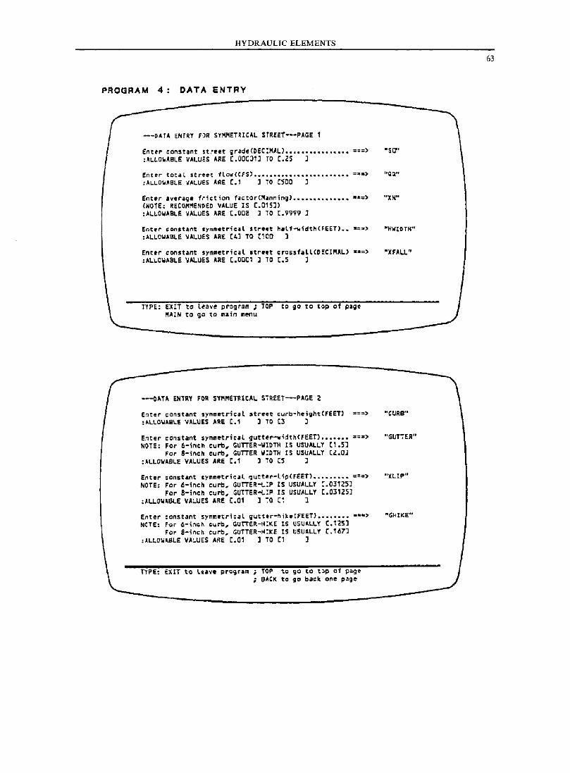
HYDRAULIC ELEMENTS
PROGRAM 4 DATA ENTRY
---DATA ENTRY FOR S~MMETRICAL STREET···PAGE 1
fnte,. constant strl!et grad'e(DEC!HALJ ................. ===) "SO" :'LLo.ABLE VALUES ARE C.00C01l TO C.'5 l
Enter tQt-il $tr~e-t 1low(CF$) ................................ ===> "Qil" :AL.LO\,jABLE ... .ALUES A.RE c., J TO (sao ;
Entl!r iveraq. friction f.ctor(~.nnin9) ................. ~a=) (NOTE: RECOMMENDED VALUE IS C.015) :Al~OWABlE VALUES ARE C.OD8 J TO [.9999 J
Ent"" c;onst."t symmetric4l street h.lf ..... idth(FEET) ... _=d :Al1..0WABLE VALuES ARE (4) 10 (100 ]
Enttr eonstant symlllet";cal Itre,t crossf.U(DECII"lAL) ===) :ALLOWABLE VALUES ARE C.00C1 l TO C.S l
TYPE: Uli to leave program; TOP to go to top of page ~AIN to go to ~ain al!nu
Enter constant symmetrical street cUib-neiihtCFEETl ~==) : IILLO\lA8\,.E VAlUES ARE 1:.1 J TO (3 J
Enter ccn5t~nt symm~tric'l gutte~~idth(FEET) ••••••• ~;=, NOTE: For 6-;neh curb, GUTTER-WIOTH IS USUALLY (1.5]
For 8-;l"Ich cut'b, GUTTER WIDTH IS USUAI..LT (Z .. QJ : ALLOWA81..E VAI..UES ARE 1:.1 ] TO (5 J
Enter :onst~nt symm.tr;cal ~utt@r-l;~(FEET) ••••••••• ==:> NOTE; Fer 6-inch cure, GUTTER-LIP IS USUALLY C.03125J
Fer B-inch curb, GUTTER-t,.IP IS USUALLY C.03125) :~LLow,eLE VACUES ARE C.Ol l TO Cl l
Enter :cnstant symmRtrical gutt.r-hik.{fEET) ••••••••• =.> NeTE: FiJi 6-i\\~1\ ;yrb, GUTIER.-HIKE IS USUAl.L.Y C.125]
F~r a-inch curb. GuTTER-H!kE IS USUALLY (.167] :ALLOW"SLE VAI..UES ARE C.01 ] TO (1 J
T'f'P£: EXIT to lou ..... pro9ri11'11 ; TOP to go to tOp 01 page ; BACK to go b~ck one pa;e
"XN.'·
"HWtDTH"
"XFAU"
"CURS"
"GIJTTEAU
")ClIP"
"G~IKE"
63
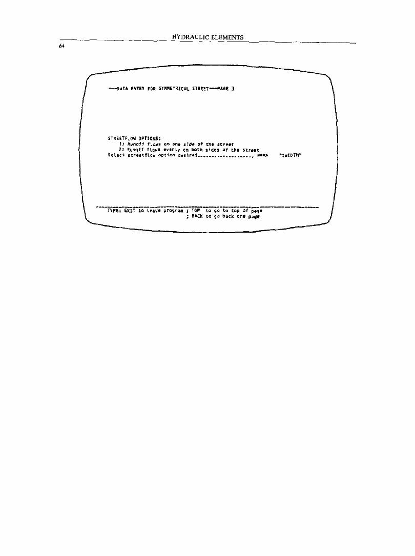
HYDRAULIC ELEMENTS
64
---OATA ENTRY FOR SY~ETRICAL STReET---PAGI l
STREETFLOY OPTIONS: 1: ~~nof1 f~Q~s Qn on. ,id~ 01 tbe 'trf~t 2: Runaf1 flQWI eVlnly on DOt~ Sid!S at th. street
SeL.~t street fLew o~tion desir@d~~ ..................... >
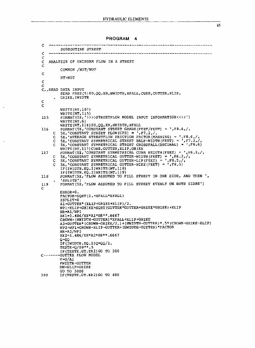
HYDRAULIC ELEMENTS
PROGRAM 4
C ---------------------------------------------------------------------SUBROUTINE STREET
c ---------------------------------------------------------------------C C ANALYSIS OF UNIFORM FLOW IN A STREET c
C
C C C •• READ
C C
115
116 C C C C
117 C C C
118
119 C
COMMON /NUT/NUT
NT;NUT
DATA INPUT READ fREE(5)SO,QQ,XN,HWIDTH,XFALL,CURB,GUTTER,XLIP, GBIKE, !WIDTH
WRITE (NT, 187) WRITE (NT, 115) FORMAT (IX, '»»STREETFLOW MODEL INPUT INFORMATION««') WRITE(NT,6) WRITE(NT,116)SO,QQ,XN,HWIDTH,XFALL fORMAT (5X, 'CONSTANT STREET GRADE (FEET/FEET) = ',F8.6,/, 5X,'CONSTANT STREET FLOW(CFS) = ',F7.2,/, 5X,'AVERAGE STREET FLOW FRICTION FACTOR(MANNING) ; ',FB.6,/, 5X,'CONSTANT SYMMETRICAL STREET HALF-WIDTH(FEET) ; ',F7.2,/, 5X,'CONSTANT SYMMETRICAL STREET CROSSFALL(DECIMAL) ; ',FB.6) WRITE (NT,117)CURB,GUTTER,XLIP,GBIKE FORMAT (5X, 'CONSTANT SYMMETRICAL CURB HEIGTH(FEET) ; ',F6.2,/, 5X,'CONSTANT SYMMETRICAL GUTTER-WIDTH(FEET) = ',F6.2,/, 5X,'CONSTANT SYMMETRICAL GUTTER-LIP(FEET) ; ',Fa.5,/, 5X,'CONSTANT SYMMETRICAL GUTTER-HIKE(FEET) = ',FB.5) IF(IWIDTH.EQ.1)WRITE(NT,l18) IF(IWIDTH.EQ.2)WRITE(NT,l19) FORMAT (5X, 'FLOW ASSUMED TO FILL STREET ON ONE SIDE, AND TEEN " r SPLITS')
FORMAT (5X, 'FLOW ASSUMED TO FILL STREET EVENLY ON BOTH SIDES')
ERROR~O. FACTOR;SQRT(l.+XFALL*XFALL) ISPLIT;O Al;GUTTER*(XLIP+GHIKE+XLIP)/2. WPl;XLIP+GEIKE+SQRT(GOTTER*GUTTER+GHIKE*GHIKE)+XLIP HR=Al/WPl XKl=1.486/XN*Al*HR**.6667 CROWN; (HWIDTH-GUTTER)*XFALL+XLIP+GHIKE A2=GUTTER* (CROWN-GHIKE/2.) + (HWIDTH-GUTTER) *.5* (CROWN-GHIKE -XLIP) WP2;vIPl +CROWN-XLIP-GUTTER + (HWIDTH-GUTTER) *F ACTOR HR=A2/WP2 XK2;1.486/XN*A2*SR**.6667 Q;QQ IF(IWIDTB.EQ.2)Q;QQ/2. TESTK=Q/SO**.5 IF(TESTK.GT.Y.Kl)GO TO 300
C-------GUTTER FLOI~ MODEL V=Q/Al FWIDTH -GUTTER DN~XL IP+GH IKE GO TO 3000
300 IF(TESTK.GT.XK2)GO TO 400
65
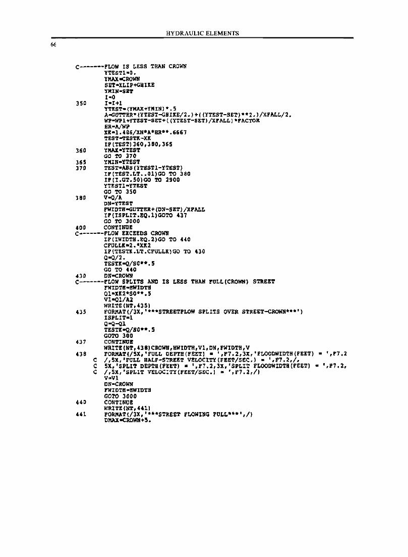
HYDRAULIC ELEMENTS
C-------FLOW IS LESS THAN CROWN YTES'l'l-a. YKAXoCROWN SET-XLIP+GBUE YHIN-SET 1-0
350 I-HI Y'l'ES'l'-(YMAX+YHINJ·.5 A-GU'l"l'ER·(YTEST-GBIKE/2.J.«YTEST-SET)··2.)/XFALL/2. WP-WPl+YTEST-SET+«YTEST-SETJ/XFALL1'FACTOR HR-A/WP XK-I.486/XN·A·HR··.6667 'l'ES'l'-TESTK-XK I1'(T£ST)360.380.365
360 YKAX-YTEST GO TO 370
355 YMIN-ITEST 370 TE5T-ABS(YTE5TI-YTEST)
I1'('l'EST.LT •• Ol)GO TO 380 I1'(I.GT.50)GO TO 2900 YTE5n-YTEST GO TO 350
380 V-o/A DN-Y'l'EST FWIDTllaGU'l"l'ER. (ON-SET) /XPALL IP(ISPLIT.EO.l)GOTO 437 GO TO 3000
400 CONTlNOE C-------FLOW EXCEEDS CROWN
IF(IWIDTH.EQ.2)GO TO 440 CFULLa:-2.·Xlt2 11(TESTl.LT.CFULL1)GO TO 430 0-0/2. TESTK-a/Sou .5 GO TO 440
430 DNaCROWN C-------FLOW SPLITS AND IS LESS THAN FULL(CROWN) STREET
FWIDTS-I!WIDTII Ql-X12·SO".5 VI-Ql/Al WRITE (NT,'3S)
435 FORMAT(/3X.····STREETFLOW SPLITS OVER STaEET-CROWN····) I5PLIT-l Q-o-Ql TESTlt-o/Sou.5 GOro 300
431 CONTINOE WNITE (NT. 438) CROWN,HWIDTH.Vl. DN,FWIDTH.V
438 FORMAT(/5X.·FULL DEPTH(PEET) - '.F7.2.3X,'FLOODWIDTH(FEET) - '.1'7.2 C /,SX,'FOLL HALF-STREET VELOCITY (FEET/SEC.) - ·,P7.2,/, C SX,'SPLIT DEPTB(FEET) - ·,F7.2,3X.·SPLIT FLOODWIDTB(FEET) - ·,P7.2, C /,SX, 'SPLIT VELOCITY(FEET/5EC.) - '.F1.2,/)
VaVl ON-CROWl! FWIDTH-I!WIDTH GO'l'O 3000
440 CONTINUE WRIT! (NT. 441)
441 FORMAT(/3X.·· •• STREET FLOWING FULL····./) DKAXoCROWN+5.
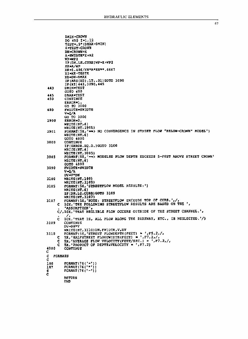
HYDRAULIC ELEMENTS
DKIN oCllOIlll DO 450 t-l, 12 ~tST-.S-(DKAX+DMIN) X -TEST-CROWN DNooCR01fH+K A-IIIIIDTlI t X+A2 WP-wP2 IP(CN.L!.CUllB)WP-X+WP2 HR-A/liP XK-l.'8~/XN·A·HR··.6667 XZ-JlII-T£:STIt XD-CN-C~ IP(ABS(XD).LT •• al)GOTC 3090 IP(XZ) "3,l090,44S
'43 DMIN-TESr GaTe HI!
445 DNAX.TEST 450 CONrINOE
ERROR-l. GO TO 3000
480 FWIoTH-ffWIDTB V~/A GO TO 3000
2900 ERROR-2. WIUTE(NT,6l WRITE (NT,2901)
2901 FORMAT(5X,' •• ) NO CO~RGENCE IN STREET FLOW "BELOW-CROWN' KaDEL') WRITE (NT,ti) GOTe 4000
3000 CONTINUE IP(ERROR.EQ.O.)GOTO 3100 WRIrE(NT,6) WRITE(NT,JOOS}
3005 FOllHAT(SX,"-> MODELED PLOW DEPTH EXCEEDS 5-FEET ABove ST~EET CROWN' WP.ITE(NT,61 COTe 4000
3090 FWIDTH-ffWIDTH "'-0/" OV-V-Dll
3100 WRITS(NT,180) WRITE(NT,JIOS)
3105 FQRMAT(SX,'STRE&Tr~OW KODEL RESULTS,') WRITE (NT,6J IF(DN.Lt.CgRB)GOTO 3109 WRITE: (NT, 3107)
l1a7 FORHAT(SX,'HOTE, STREE~rLOW EXCE~OS TOP OP CURB. ',1, C lOX,'THE FOL~OWING STREETFLOW REsUtTS ARE BASED ON TB~ " • 'USUKFTIOH'. CI,lOX, 'THAT NEGLIBt! FLOW OCCURS OUTSIDE OF THE STREET CBANNEt.',
I, e lOX, 'THAT IS, ALL FLOW ALONG THE PARKWAY, ETC., IS NEGLECTED. 'I)
3109 CONTINUE DV"DN-V WRITE(NT,3110)DN,FWIDTB,V,DV
3110 FORMAT(5X,'STREET FLOWDEPTH(FEET) - ',F5.2,f, e 5X,'KALFSTREET FLOODWIDTH(FEET) • ',E7.2,/, t SX,'AVERAGE rLOW ... !tOCITY(FEET/SEC., • ',F7.2,/, C SX,'PRODUCT OF DEPTH'VELOCITY • ',17.2)
4000 CONTlNUE: C C FORIIATS C 180 FQRMAT(H ('-') 187 PORMAT(76('·')) 6 FORMATI7G('-')) c
RETURN END
67
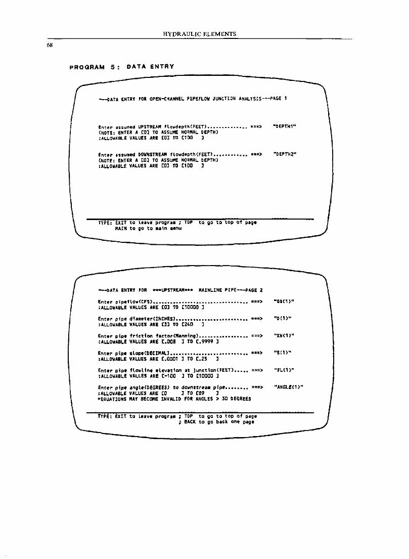
68
HYDRAULIC ELEMENTS
PROGRAM 5: DATA ENTRY
--CATA ENTRY FOR OPEN-(HANNEI. PIP£FLOW JUNCTION ANALYSIS---PAGE 1
Enter assym.d UPSTREAM flewdept~(FEET) •••••••••••••• z:z> (NOTE: ENlE' A (Ol TO ASSUME NORMAL DEPTH) :AI.LO\,lA.BL! VAlUES ARE [0] TO C100 J
ent.~ Issu~ed OOW"STR£AM flovde~tn(FEET) ••••••••••••••• > (NOTE: ENTiA A (Ol TO ASSUME NORMAL DEPTH) :ALLOWABLE VALUES ARE CO] TO Cl0a ]
TYPE: EXIT to tea.." prograll i TOoP to;o to' top of g~~. MAIN to go ta .~in aenu
--~ATA ENTRY 'OR ***UPSTAEAM". MAINLINE PIPE---PAGE 2
Ent~r pip.flov(CFS) ••••••••••••••••••••••••••••••••• -==> :ALLOWABLE VALUES AAE CO] TO C10000 ]
Enter pipe diameterCINCHES) •••••••••••••••••••••••••••• > :ALLOWABLE VALUES ARE C3l TO C240 J
Enter pipe friction f.ctor(Manning) ••••••••••••••••• ===> :ALLowABLE VALUES AAE [.OOS ] TO [.9999 ]
Enter pip. slope(CEClMAL' ••••••••••••••••••••••• ~ ••••• _) :ALLOWABLE VALUES ARE [.0001 ] TO [.25 J
Enttr p;~t flowltnt .le~.tiQn ~t junctianCFEET) ••••• ===> :ALLOW.BLE VALUES ARE [-100 J TO Cl0000 J
Entr~ pip •• n,t.COEGRE£S) to dovnstr.~. ~f~ ••••••••• ===> :AL"OWAS"E VALUES ARE CO ] TO [89 ] -eQUATIONS .AY BECOME INVALID FOR ANGLES ) 30 DEGREES
TYPE: EXIT to Leave pro;r~. ; TOP to qa to top of ~age ; BACK to go back ant page
·CEPTH1"
-DEPTH2"
··XN(1,"
"se,,"
"ANGLEC1 )"
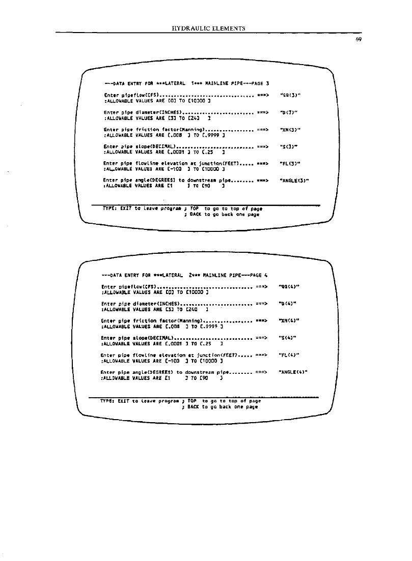
HYDRAULIC ELEMENTS
---oATA ENTRY FOR •• *LATERAL , ... MAIN~INE PtPE---PAGE 3
Enter p1~.flow(CFS) ••••••••••••••••••••••••••••••••• ~~.) :ALLO~ASL£ VALUES ARE CO] TO (10~OO 1
Ent~r ~tpe diamet.rCINCHES) ••••••••••••••••••••••••• ===> :ALLOW,eLE VALUES ARE ~l] TO ~Z40 ]
enter ~;~. 1r;~tien f.ctct'"ann'ng) ••••••••••••••••• ===> :ALLOWASl.E VALUES ARe [.OOS J TO [.9999 J
Enter gip, .Lop.CDfClMALJ ••••••••••••••••••••••••••• ==3> :ALLOWABLE VALUES ARE [.CC01 l TO C.Z5 l
ent~r ~ip. flowline elevation at juncticnCFEET) ••••••• a)
:AW-O.ABLE VALUES ARE [-lOa l TO [10000 ]
Enter pipe IngleCDEGREES) to do~nstre •• pip ............ > ;A~OWABLE VALUES ARI [1 1 TC C90 ]
TYPE: EXlT to lnve prOif ... ; TOP to go to top of page ; SACK to 90 ba~k one page
---DAU ENTRY FOR *-LATERAL 2 ... MAINLINE PIPE-P.GE 4
Enter p;g.fLc~(C'S) ••••••••••••••••••••••••••••••••• ===> :ALLOWAeLE VALUES ARE [OJ TO [10000 l
Enter pipe diameter(INCHeS) ••••••••••••••••••••••••• ===) :AlLOWABL! VALUES ARE e3l TO [240 1
Enter g;p. fr1ct1o" factor(Ma"n;ng) ••••••••••••••••• as.> :ALLOWABLE VALUES ARE [.ooa 1 TO [.9999 1
Enter pipe slop.(DECIMAL) ••••••••••••••••••••••••••• ===> ,ALLOWABLE VALUES ARE [.0001 ] TO [.25 J
Ent.r gipe flQ_Line .lev~tion It jun'tion(FEET) ••••• ==~> :ALLOWABLE VALUES ARE [-lOa ] TO Cl0000 1
Enter ~ipe ~ngleC~EGR!E$) to do~nstream pip ••••••••• ===~ :ALLOWASLE VALUES ARE [1 ] TO r90 J
TYPE: EXIT to l~.~e progr._ ; TOP to go to tap of page ; BACK to go back one- page
69
"QQ(3)"
",)(3)"
·XN(J)'·
"FL(3)"
·ANGLE(3)"
"0 (4)"
··5(4)"
"FL(4)"
".l.NGLE(4)"
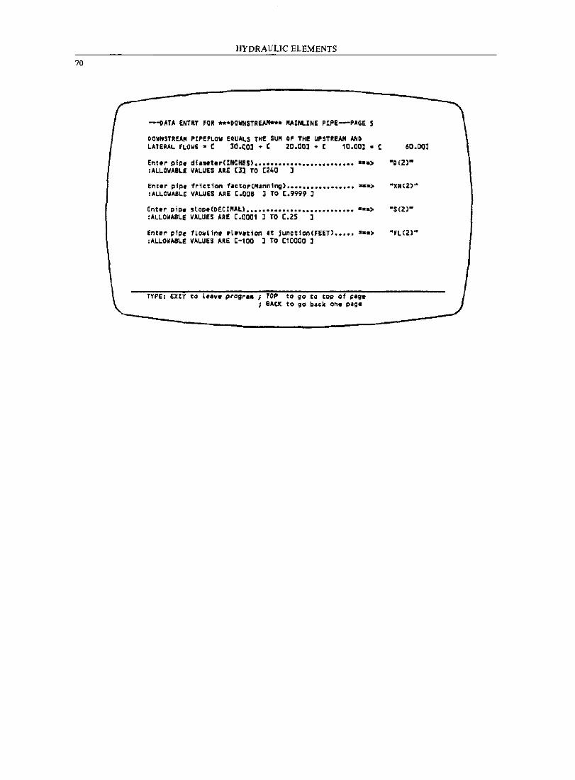
70
HYDRAULIC ELEMENTS
---oATA ENTRY FOR ••• DOWNSTREAM'" OAINLINE PIPE---PAGE 5
~OWNSTREAM PIPE FLOW EQUALS THE SUM OF TH! UPSTREAM AND LATERAL FLOWS' [ 30.00]. [ 20.00]. [ 10.00]. [ 60.00]
Ent.~ pi~f diam.t.rCINCHES) •••••••••••••••••••••••••••• ) -D(2)-,ALLOWABLE VALUES ARE Cll TO C240 ]
En~.r pf~. friction factor("jn~1ng> ••••••••••••••••• ... > -)N(Z)" :AlLOWASL! VALUES ARE t.QCa J TO [.9999 J
Ent.r gipe sLop.(DECIMlL) ••••••••••••••••••••••••••• a •• ) ·S(2)-,ALLOWA.LE VALUES ARE C.OOOl J TO [.25 ]
Enter pipe fLowLin. tL'~ltion It junction(fEET) ••••• a.a) "fl(2)" :ALLOWABLE VALUES .RE C-l00 ] TO [10000 ]
TYPE: EXIT to l~.v. p~agr •• ; TOP to go to tap af ~.g~ BACK to go b.ck one page
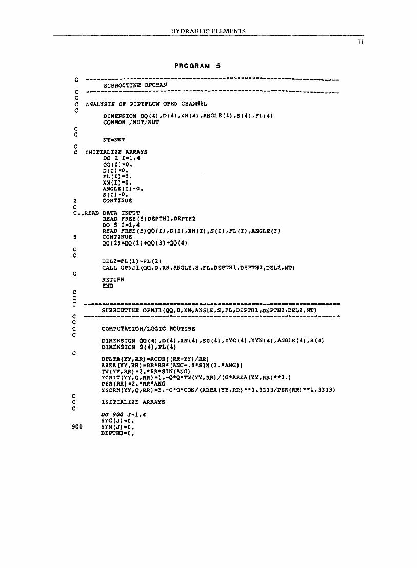
HYDRAULIC ELEMENTS
PROGRAM 5
C ---------------------------------------------------------------------SUBROUTINE OPCBAN C -----------------------------------------------------------------___ _ C C ANALYSIS OP PIPEPLOW OPEN CBANNEL C
C C
C C
2 C
DIMENSION OO(41,D(41,XN{4},ANGLE(41,S(4),FL(41 COIIMON /NUT/NUT
INITIALIZE ARRAYS 00 2 1-1,4 00(11-0. 0(1) -0. Ft(I)-O. XN(Il-O. ANGt£(Il-O. S(I)-O. CONTINUE
C •• READ DATA INPUT
5
C C
C
C C
READ FREE (5)OEPTHl,OEPTB2 DO 5 1-1,4 READ FREE(S)OO(I) ,0(1) ,XN(I),S(I) ,FL(I),ANGLE(I) CONTINUE 00(2)-00(1)+00(3)+00(4)
DEtZ-l't (1 J -Ft (2) CALL OPNJl(OO.D.XN,ANGLE.S.FL.OEPTH1,OEPTH2.0ELZ,NT)
RETURN END
C ---------------------------------------------------------------------SUBROUTINE OPNJl(OO,D,X~,ANGLE,S,FL.DEPTB1.DEPTB2,DELZ,NT) C ---------------------------------------------------------------------C C COMPUTATION/LOGIC ROUTINE C
C
C
OIMENSION OO(4),D(41,XN(4),SO(4l,YYC{4l,YYN(4),ANGLE(4J,R(41 OIMENSION S(41,FL(4)
DELTA(YY,RR)-ACOS((RR-YY)/RR) AREA(YY,RR)-RR·RR·(ANG-.S·SIN(2.*ANGl) TW(YY,RR)-2.*RR·SIN(ANG) YCRIT(YY,O,RR)-1.-o*O*TW(YY.RRl/(G*AREA(YY,RR)··3.} PER(RR)-2.·RR*ANG YNORM(YY,O,RR)-1.-O·O·CON/(AREA(YY,RR)··3.3333/PER(RR)··1.3333)
C INITIALIZE ARRAYS C
DO gOO J-l,4 YYC(J)·O.
900 YYN(J)-O. DEPTH3-0.
71
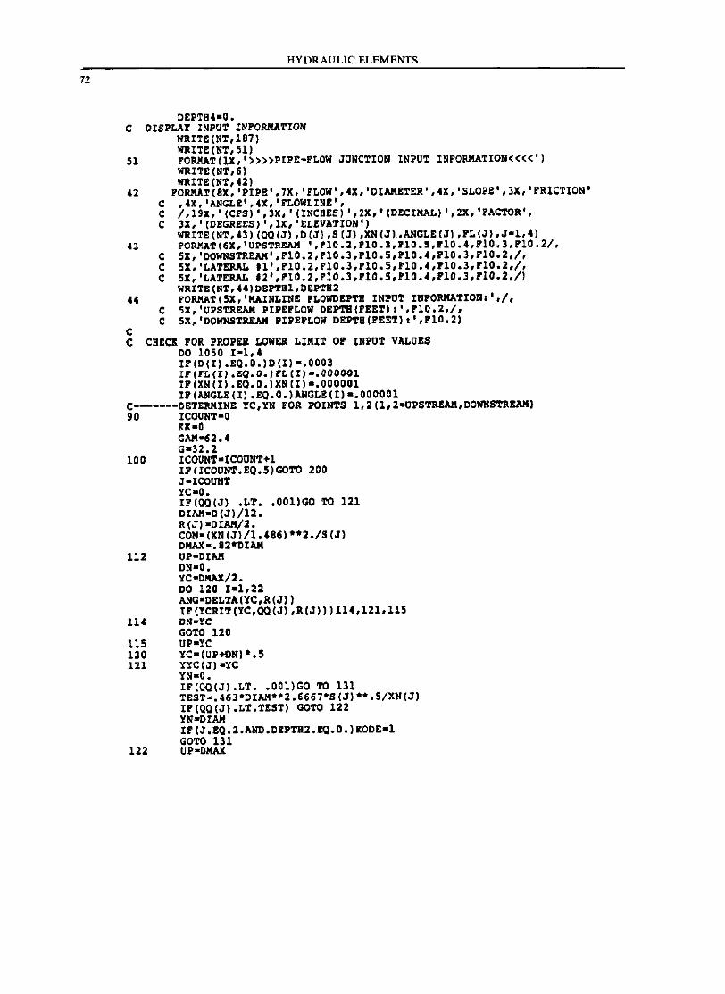
72
HYDRAULIC ELEMENTS
DEPTB4-0. C DISPLAY INPUT INFORMATION
WRIU (NT,187) WRn2(NT,51)
51 FORMAT(lX.'»»PIPE-FLOW JUNCTION INPUT INFORMATION««') WRITE (NT,6) WRITE (NT,42)
42 FORMAT(8X,'PIPE',7X,'FLOW',4X,'DIAM£TER',4X,'SLOP2',3X,'FRICTION' C ,~X,IANGLE',4X,lrLOWLINE', e / ,19x, , (CFS) " 3X, , (INCBES) ',2X.' (DECIMAL) " 2X, 'FACTOR', C 3X.' (DEGREES) , ,IX, , !LEVATION' )
WRITE (NT, 43) (Q(I (J), D (J) ,S (J),XN (J),ANGLE (J) ,FL (J) ,J-l, 4) 43 PORMAT(6X,'UPSTREAM ',P10.2,P10.3,F10.5,FI0.4,F10.3,'lO.2/.
C 5X,'DOWNSTR£AM',,10.2,'lO.3,'10.5,FI0 •• ,FI0.3,F10.2,1, e SX,'LATERAL '1','10.2,FI0.3,'10.5,PI0 •• ,'10.3,P10.2,1, C SX,'LATERAL .2','10.2,'10.3,'10.5,110 •• ,F10.3,F10.2,/)
WRITB(NT,44)DEPTB1,DEPTB2 44 FORMAT(5X,'MAINLINE PLOWD£PTB INPUT INFORMATIONa',I,
e 5X,'UPSTREAM PIPE'LOW DEPTB(F££T)a',PI0.2,/, e SX, 'DOWNSTREAM PIPEFLOW DEPTS(FEET) a ','10.2)
C C C8EeK FOR PROPER LOWER LIMIT 0' INPOT VALUBS
DO 1050 1-1,4 I'(D(I).EQ.O.)D(I)-.0003 IF(FL(II.EO.O.IF~(II·.OOOOOI IP(XN(I).EQ.O.)XN(I)-.OOOOOI IP(ANGLE(I).EQ.O.)ANGLE(I)-.OOOOOI
C-------DETERHINE YC,YN FOR POINTS 1,2(1,2-UPSTREAM,DOWNS'rRBAM) 90 ICOUNT-O
IIl-0 GAM-62.4 G-32.2
100 ICOUNT-ICOUNT+l IP(ICOUNT.EQ.5)GOTO 200 J-ICOUNT YC-O. IF (Q(I(J) .LT •• 001)00 TO 121 DIAM-D(J)/12. R(J}-DIAII/2. CON_(XN(J)/1.486)**2./S(J) DIIAX-.82*DIAM
112 UP-DIAM DN-O. YC-DMAX/2. DO 120 1-1,22 ANG-DELTA(YC,R(J)) IF(YCRIT(YC,Q(I(J),R(J)))11.,121,115
114 DN-rc GOTO 120
US UP-YC 120 YC-(UP+DN} *.5 121 YYC(J)-YC
YN-O. IF(QQ(J).LT •• 001)GO TO 131 TEsr-.463*DIAM**2.6667*S(J)**.5/XN(J) IP(QQ(J).LT.TEST) OOTO 122 YN-DIAH IF (J.EQ.2.AND.DEPTB2.EQ.0.)KDDE-l GOTO 131
122 UP-OIIAX
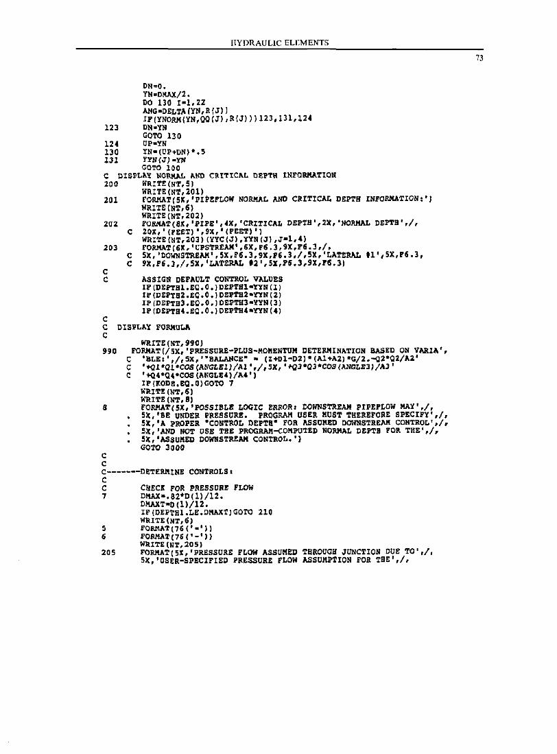
ON~O.
YN-DKAX/2. DO 130 1-1,22
HYDRAULIC ELEMENTS
ANG-OELTA(YN,R(J» IP(YNORK(YN,OQ(J),R(J»)123,131,124
123 ON-YN GOTO 130
124 UP-YN 130 YN-(UP+DN)*.S 131 YYN(J)-YN
COTO 100 C DISPLAY NORMAL AND CRITICAL DEPTH IN~ORMAT10N 200 IIR1T£(&T,5)
IIR11'E(&1',201) 201 rORKA1'(5K,'PIPEFLOW NORMAL AND CRITICAL DEPTH INFORMATION,')
IIR1'1'&(N1',6) lIRI'1'&(N1',202)
202 rOMAT(6X, 'iIPl!' ,4X, 'CRITICAL Dl!PTS',2X, 'NORMAL DEPTH' ,I, C 20X,' (FEn) ',9X,' (PEET)')
lIRITE(NT,203) (YYC(J),1YN(J) ,J-l,4) 203 rORKAT(&X,'UPSTREAM',6X,F6.3,9X,F6.3,1.
C 5X,'OOWNSTREAM',5X,F6.3,9X,P&.3.1,5X,'LATERAL'l',5X,P6.3, C 9X,F&.J.I,SX,'LATERAL '2',5X,P&.3,9X,16.3)
C C ASSIGN OEFAULT CONTROL VALUES
IF (DEFTBl.EO.O.)DEPTBl-1YN(ll IF(DEPTB2.EO.0.)DEPTUZ-1YN(Z) IP(DEPTS3.EO.O.)DEPTU3-YYN(3) IP(DEPTB4.EQ.O.)DEPTH4-1YN(4)
C C DISPLAY FORKU~ C
lIRITE(NT,990) 990 FORMAT(/SX,'PRESSURE-PLUS-MOMENTUM DETERMINATION UASED ON VARIA',
C 'ULE. ' ,/, 5X, "BALANCE' • (HOI-D2)' (Al+A2) ·G/2.-QZ*02/A2· C '+QI*Ol*COS(ANGLEll!AI',!,SX,'+QJ'OJ*COS/ANaLEJIIAJ' C '+Q'*Q'*COS(ANGLE4)/A")
IP(KODE.EQ.O)GOTO 7 WRITE (NT, 6) lIRITE (NT, 8)
8 FORKAT(5X, 'POSSIBLE LOGIC ERROR. OOWNSTREAM PIPEPLOW MAY'./, SX,'BB UNDER PRESSURB. PROGRAM USER MUST THEREFORE SPECIFY',I, SX,'A PROPER "CONTROL DEPTa" FOR ASSUMED DOWNSTRE~ CONTROL',I. SX,'AND NOT DSE THE PROGRAft-COKPU~ED NORMAL DEPTH FOR THE',/, 5X,'ASSUMED DOWNSTRE~ CONTROL.')
C C
<iOTO 3000
C-------OETERM!NE CONTROLS. C C 7
5 6
205
caECI POR PRESSORE FLOW D~a.a2*D(1)/12. D~T·D(1J/12. IF(DEPTB1.LE.D~T)GOTO 210 1I1UTE(NT.&) FORMAT(7S(' -'» FORMAT(7S ('-'» WIUTE (NT, 20 5) FORMAT(5X,'PRESSURE FLOW ASSUMED THROUGH JUNCTION DUE 1'0',1, 5X,'OSER-SPECIFIED PRESSURE FLOW ASSUMPTION FOR T9E',/,
73
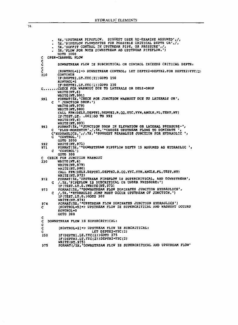
74
HYDRAULIC ELEMENTS
5X,'UPSTREAM PIPEFLOW. SUGGEST USiR as-EXAMINE ASSUMED',/, SX,'PIPEFLOW FLOWOEPTBS FOR POSSIBLE CRITICAL DEPTH OR',/, 5X,'SOPPIT CONTROL IN UPSTREAM PIPS, OR PRESSURE',I, SX,'PLOW POR BOTH DOWNSTREAM AD UPSTREAM PIPEFLOW.') GOTe 3000
C OPEN-CHANNBL PLOW C C DOWNSTREAM FLew IS SUBCRITICAL OR CONTROL EXCEEDS CRITICAL DEPTH, C C [KONTROL-ll-> DOWNSTREAM CONTROL; LET DEPTH2-DEPTHZ,FOR DEPTH2}YYC(21 210 CONTINUE
IP(DEPTB2.LT.YYC(2»GOTe 250 l{ONTROL-l IP(DEPTHl.LT.YYC(l»GOTO 230
C ••••••• CHECK FOR WASHOUT DUB TO LATERALS OR DELZ-DBCP WRITE (NT, 6) WRITE (lI'r, 99l)
991 FOllllAT( SX, 'CIIECK FOR JUNCTION WASHOUT DUB TO LATeRALS OR'. C 'JUNCTION DROP,')
WRr'!'! (NT, 979) WRITE (lI'r, 980) CALL PPM(DELZ,DEPTBl,DEPTB2,R,OO,YYC,YYH,ANGLE,PL,TEST,NT) IF (TESi'.Li' •• 001)GO TO 992 WRITE(tlT,6J WRITE (lI'r,993)
993 FOllllAT(5X,'*JUNCTION DROP IN ELEVAi'ION OR LATERAL PRESSURE-', C 'PLUS-MOMENTUM',I,5X,'·CAUSES UPSTREAM PLOWS TO DOKINATE " C'HYDRAULICS.',1,5X,'·SUGGEST REANALYZB JUNCi'ION FOR HYDRAULIC " C 'COll'rROL. ' J
GCTO 3000 992 WRITE(NT,911J 971 FORMAT(SX,'*DCWNSTREAK PIPEFLOW DEFTB IS ASSUKED AS HYDRAULIC "
C I CONTROL' ) GCTO 300
C CHECK FOR JUNCTION WASHOUT 230 WRITE (NT,5J
WRI'rE (lI'r, 979) WRITE(NT,980) CALL FPM(DELZ,DEPTS1,DEPTH2,R,QQ,YYC,YYN,ANGLE,FL,TESi',NT) WRITE (N'1',972)
97Z FORMAT(SX,'UPS'1'RE~ PIPEFLOW IS SUPERCRITICAL, AND DOWNSTREAM', C J,SX,'PIPEFLOW IS SOBCRITICAL OR UNDER PRESSURE,')
IF (TEST.LT.O.)WRITE (Ni', 973) 973 FORMAT (SX, "DOWNS'l'REAM FLOW DOMINAfES JUNCTION HYDRAULICS',
C /,SX,"SYDRAULIC JUMP MUST OCCUR UPSTREAM OF JUNCi'ION.') IF(TESi'.Li'.O.)GOTO 300 WRIT!! (NT, 974 J
974 FORMAT(5X,"UPSi'REAM FLOW DOMINATES JUNCTION HYDRAULICS') C [KONTRaL-51-> UPSTREAM FLOW IS SUPERCRITICAL AND WASHOUT OCCURS
KONTROL-5
<: C C C C 250
975
GOTO 300
DOWNSTREAM FLOW IS SUPERCRITICAL,
[~ONTROL-21-> UPSTREAM FLOW IS SUBCRITICAL; LET DEPTB2-YY<:(2)
IF(OEPTB1.LE.YYC(1»GOi'0 215 IF(OEPTB2.LT.rrC(Z»DEPTBZ-YYC(2) WRITE (N'l',975) FORMA'l'(/SX,'OOWNSi'REAM FLOW IS SUPERCRITICAL AND UPSTREAM FLOW'
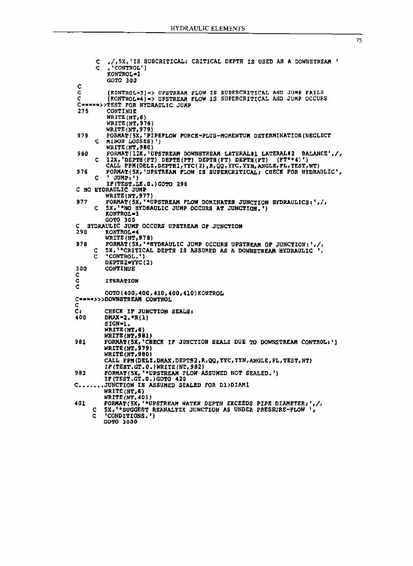
C
HYDRAULIC ELEMENTS
C ,1,5X,'IS SOBCRITICAL: CRITICAL DEPTH IS OSED AS A DOWNSTREAM ' C ,'CONTROL')
KONTROL-2 GOTO 300
c (~ONTnOL-J)-> UPSTREAM FLOW IS SOPERCRITICAL A~D JUMP FAILS C [KONTROL.4).> UPSTREAM FLOW IS SUPERCRITICAL AND JOMP OCCURS Cs···.»TEST rOR HYDRAULIC JUMP 275 CONTINUE
WRITE(NT,5) WRITE(NT,976) WRITE (NT,979)
979 FORKAT(5X,'PIPEFLOW FORCE-PLOS-MOMENTOM DETERMINATION(NEGLECT C MINOR LOSSES) 'J
WRITE(NT,980) 980 FORKAT(12X,'UPSTREAM DOWNSTREAM LATERAL.I LATERAL.2 BALANCE',I,
C 12X,'DEPTH(FT) OBPTB(PT) DEPTH(FT) DBPTH(FT) (FT"4) ') CALL FPM(DELZ,DEPTHl,lYC(2),R,QQ,lYC,lYN,ANGLE,FL,TEST,NT)
976 FORKAT(SX,'OPSTREAM FLOW IS SOPERCRITICALI CHECK FOR HYDRAULIC', C 'JUMP,')
IF(TEST.LE.O.)GOTO 290 C NO SYDRAULIC JUMP
WRITE (NT,977) 977 FORKAT(5X, "UPSTREAM PLOW DOMINATES JUNCTION HYDRAULICS,',/,
C SX,"NO HYDRAULIC JUMP OCCURS AT JUNCTION.') KONTROL·] GOTO 300
C HYORAULIC JUMP OCCURS UPSTREAM OF JUNCTION 290 KONTROL.4
WRITE (NT,978) 978 FORKAT(5X,"SYDRAULIC JUMP OCCURS UPSTREAM OF JUNCTION: ',/,
C 5X,"CRITICAL DEPTH [S ASSUMED AS A DOWNSTREAM HYDRAULIC " C 'CONTROL.')
DEPTHZ·'CtC(2) 300 CONTINUE C C ITERATION C
GOTO(400,4QO,410,400,410)KONTROL C····»>DOWNSTREAM CONTROL C C: 400
981
982
CHECK IF JUNCTION SEALS. DMAX·Z. 'R(l) SIGN·I. WRITE (NT,6) NRITE(NT,981) FORMAT(5X,'CBECK IP JUNCTION SEALS DUE TO DOWNSTREAM CONTROL,') WRITE (NT, 97 9) WRIT!: (NT,9QO) CALL FPM (DELZ ,DMAX,DEPTII2,R,QQ, Y'YC, YYN ,ANGLE, FL,TEST, NT) IF(TEST.GT.O.)WRITE(Nr,982) FORMAT (5X, "UPSTREAII PLOW ASSUMED NOT SEALED.') IF(TEST.GT.O.)GOTO 42Q
C ••••••• JUNCTION IS ASSUMED S~ALED FOR DI>DIAMI WRITE (NT ,6)
401 NRITE(NT,401) FORMAT(5X, "UPSTREAM ~ATER DEPTa EXCEEDS PIPE DIAMETER: ',/,
C SX,"SUGGEST REANALYZE JUNCTION AS UNDER PRESSURE-FLOW', C 'CONDITIONS. ')
GOTO 3000
75
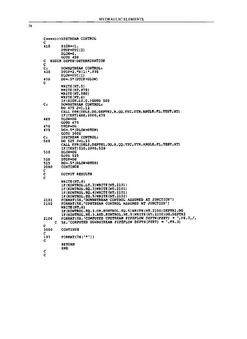
76
HYDRAULIC ELEMENTS
C •••• »>UPSTREAM CONTROL C 410 SIGN·-I.
DTOp·nc (2) DLOW·O. GaTO 450
c BEGIN DEPTH-DETERMINATION C C: 420
450 C
DOWNSTREAM CONTROL: DTOP·2.*RII)*.995 DLOW·nC(I) DG-. 5* (DTCP+DLOW)
WRITE(NT,S) WRITE (NT, 979) WRITE(NT,980) WRITE (NT, 6) IF(SIGN.LT.O.)GOTO 500
C. DOlrnSTREAM CONTROL. DO 475 J-l,ll CALL FPM(DELZ.DG.DEPTH2,R,CO,YYC,YYN,ANGLB,FL,TBST,NT) IF(TEST)460,2000,470
460 DLOW-CG GOTO 475
470 DTOP-DG 475 DG-.5*(DLOW+DTOP)
GOTO 2000 C: UPSTREAM CONTROL. 500 DO 525 J-l,13
CALL FPM(DELZ,DBPTHI,DG,R,QQ,YYC,YYN,ANGLE,FL,TEST,NT) IF (TEST) 510,2000,520
510 DLOW-DG GOTO 525
520 DTOP-DG 525 DG-.5*(DLOW+DTOP) 2000 CONTINOE C C OUTPUT RBSULTS C
2101 2102
2100 C
C 3000 C 187 C
C C
WRITE (NT,5) IF (KONTROL.LT.3)WRITE(NT.2101) IF (KONTROL.EO.3)WRITB(NT.2102) IF (KONTROL.EO.4)WRITE(NT.2101) IFIKONTROL.EO.5)WRITE{NT,2102) FORMAT(SX,'DOWNSTREAM CONTROL·ASSUMED AT JUNCTION') FORMAT(5X,'UPSTREAM CONTROL ASSUMED AT JUNCTION') WRITE (NT,6) IF {KONTROL.EQ.l.OR.KONTROL.EC.5)WRITE(NT.2100)DEPTHl,DG IF (KONTROL.NE.J.ANO.KONTROL.NE.5)WRITE(NT,2100)DG,DEPTH2 FORMAT(5X,'COMPUTBD UPSTREAM PIPEFLOW DEPTa(F!!T) _ ',F6.3,/, 5X,'COMPUTED DOWNSTREAM PIPBFLOW DEPTH(F!!T) • ',F6.3)
CONTINUE
FORMAT(16 (' *') )
RETURN END
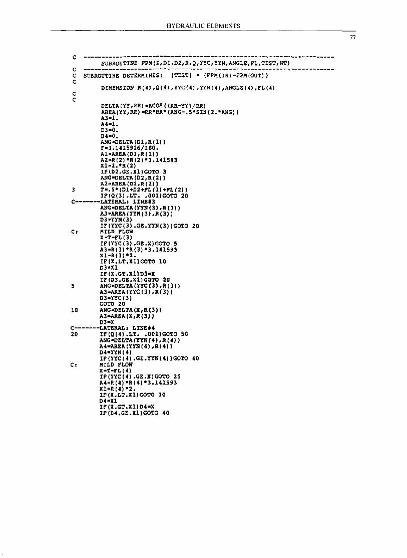
HYDRAULIC ELEMENTS
c ---------------------------------------------------------------------SUBROUTINE FPM(2,D1,D2,R,Q,YYC,!YN,ANGLE,FL,TEST,NT)
c ---------------------------------------------------------------------C SUBROUTINE DETERMINES, {TEST] - (FPM(IN)-FPM(OUTll c
C C
DIMENSION R(4),Q(4),YIC(4),YYN(4),ANGLE(41,FL(41
DELTA(YY,RR)-ACOS«RR-YI1/RRl AREA(YY,RRI-RR*RR*(ANG-.S*SIN(2.*ANG)) AJ-1. M-I. CJ-O. DC-a. ANG-CELTA (D1 ,R( I) I F-J .1415926/180. AI-AREA(D1,R(I)) AZ-R(2)*RI2)*3.141593 XI-Z. *R (21 IF(DZ.GE.Xl)GOTO J ANG-DELTA(D2,R(ZII A2-AREA(D2,R(2)I
l T-.5*(D1+D2+FL(1)+FL(2)) IF(Q(3).LT •• 001)GOTO 20
c-------LATERAL. LINE.3 ANG-DELTA(YYN(3),R(3» Al-AREA(YYN(3),R(3» D3-YIN(3) IF(YIC(3).GE.YYN(J»GOTO 20
C. MILD FLOW XoT-FL(J) IF(YYC(3).GE.X)GOTO 5 A3-R(3)*R(3)*3.141S93 Xl-R(3) *2. IF(X.LT.X1)GOTO 10 OJ-Xl IF(X.GT.xIIDJ-X IF(D3.GE.xl)GOTO 20
5 ANG-DELTA(YYc(3),R(3) A3=AREA(YYC(J),R(lll D3-YYC(3) GOTO 20
10 ANG-DELTA(X,R(l)) AJ-AREA(X,R(l)) DJ-X
C-------LATERAL. LINE.4 20 IF{O(4).LT •• 00I)COTO 50
ANG-DELTA(!YN(4),R(4" A4-AREA(YYN(4),R(C)1 D4-YIN(4) IF(YYC(4).CE.!YN(4)IGOTO 40
c: MILD FLOw X-T-Ft(4) IF(YYC(4) .CE.XIGOTO 25 A4=R(C)*R(4)*3.141593 X1=R(4)*Z. IF(X.LT.XIIGOTO 30 D4-XI IF(X.GT.Xl)D4-X IF(D4.GE.XIIGOTO 40
77
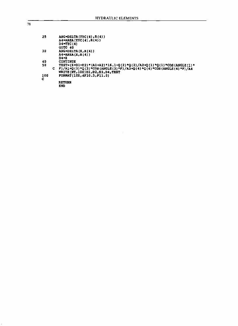
78
HYDRAULIC ELEMENTS
25 ANG-OELTA(YfC(4"R(4" A4-AREA[!YC(4),R(4» D4-ryC(4) GOTO 40
30 ANG-DELTA(X,R(4» U-AREA(X,R[4» D4-1
40 CONTINUE 50 TEST-(Z+DI-D2)"(Al+A2)"16.1-Q(2)"Q(2)/A2+Q(1)*Q[1)"COS(ANGLE(l)"
C F)/Al+Q[J)"Q[3) "COS (ANGLE [J) "P)/A3+Q(4, "Q(4)·COS(ANGL!(4) "P l/A4 WRITE(NT,lOO)Dl,D2,D3,04,TEST
100 PORKAT(10X,4PIO.3,Pll.O) C
RETURN END
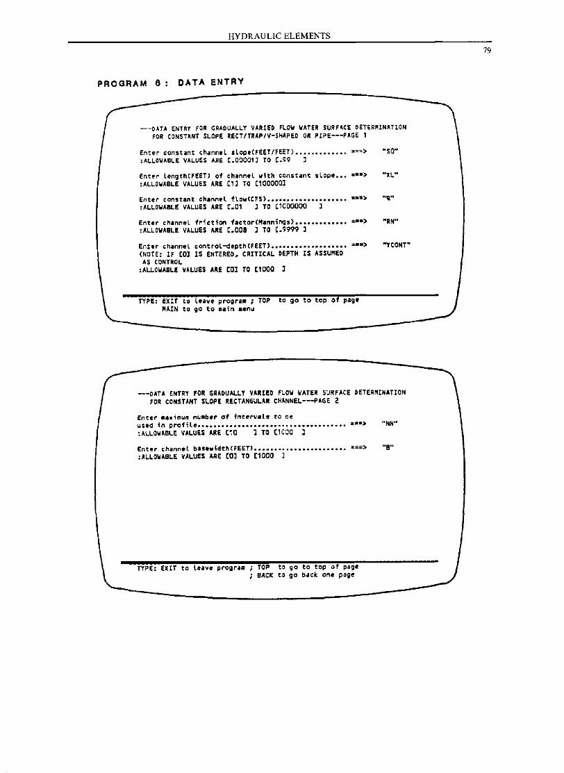
HYDRAULIC ELEMENTS
PROGRAM 6 DATA ENTRY
---OATA ENTRY FOR GRADUALLY VARIED FlOW WATER SURF~C£ OETeR~lNATION FOR CONSTANT SLOPE RECT/TRAP/V-SHAPED OR PIPE---PAGE 1
Ent~r consUnt channeL sloge<FEET/FEET) ............. ===> "SO" ;AL~O~Aele VALUES ARE t.00001) TO (.Q9 J
Ent!'r lengthCFEET) 01 channel with CQnsUnt sLoge ••• • ~W> "XL" :ALLO.ABLE VALUES ARE Cll TO Cl00000l
Enter constant cnannel ftow(CFS) •••••••••••••••••••• :sa> "1;." :ALLO.ABLE VALUES ARE C.Ol l TO Cl000000 J
Enter channeL fr1etion factorCMannings) ••••••••••••• :=*> "RN" :ALLO.ABLE VALUES ARE C.008 ] TO C.9999 l
Enter ,h.nneL control-depthCFEET) ••••••••••••••••••• 2#.)
(NOTE: IF COl IS ENTERED. CRITICAL DEPTH IS ASSU"ED AS CONTROL
:ALlO.ABLE VALUES ARE COl TO Cl00D l
TYPE: EXIT to leave progra_ ; TOP to go to top of page MAIN to go to maln .enu
"YcaNT"
---DATA ENTRY FOR GRADUALLY VARIED FLOW WATER SURFACE DETER~INATION FOR CONSTANT SLOPE RECTANGULAR CHANNEL---PAGE 2
Enter .ax1mu~ nuaber of i"t.~v.ls ta oe uSl!d in ~rofile ••••••• •••••••••••••••••••••••••••••• a._> "NN" :ALLOWABLE VALUES ARE C10 l TO (1COO 1
Ent .. ,h'nnot b .... idth(FEET) ••• _ ••••••••••••••••••• ===> "8" :ALLO.ABLE VALUES ARE COl TO Cl0DD l
TYPE: EXlT to leave progrilll ; TOP to go to top of page SACK to go back one page
79
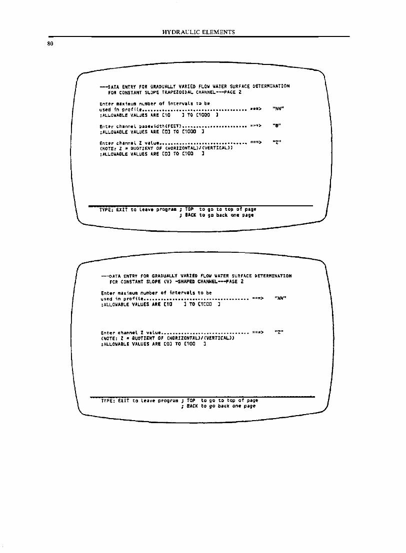
80
HYDRAULIC ELEMENTS
-~ATA ENTRY fOR •• ADUALLY VARIED fl.OW WATE. SURFACE DETER~INATION fOR CONSTANT SI..OP~ TRAPfZOIOAI.. (HANNEL--PAGE Z
Entfr m •• 1mum number of tnt~rVlll to b. used in pro1 i {e .......................................... a> "NN" :.ALLOWABLE VALUES U! C10 l TO (1000 l
Enter ,h.nnel ~ase'llidtn(FEET) ........................ ,."''''> "I" :AL.L.OWASL.E VAL.UES UE CO] TO (1000 ]
Enter chinnel Z v .. lu •••••••••••••••••••••••••••••••• ===> "t" (NOTE: Z • QUOTIENT OJ: (HOIllZONTAL)/ (VERTICAL>' :AL.L.OWASL.E VAL.UES UE [0] TO [100 J
TYPE; EXIT to lu'V. progr •• ; TOP to go to top of pol;. ; lACK to go blek one page
---oATA ENTRT FOI GRADUALLY VARIED FLOW WATER SU~F~CE OETERMINATIOH FOR CONSTA.T SL.OPE (Vl -SHAPED CH~EL---PAGE Z
Enter maximum number of i~tervils to be used in profi le ........................................... ::!Os> "NH" :'L.LOWASL.E VAL.UES ARE [10 J TO [ICeO J
Entel" cn.nn_l % v.lue ............................... .o • .o.o.o ... ===> .. z .. (NOrE: l • QUOTIENT 0' (HCRIlONTALJ/(VERTICALll :AL~OWAeL! VALUES ARE (0] TO [100 ]
TYPE: EXIT to leave prograla ; TOP ta gg to tcp of page ; SAC)( to 90 ba~k one p~g.
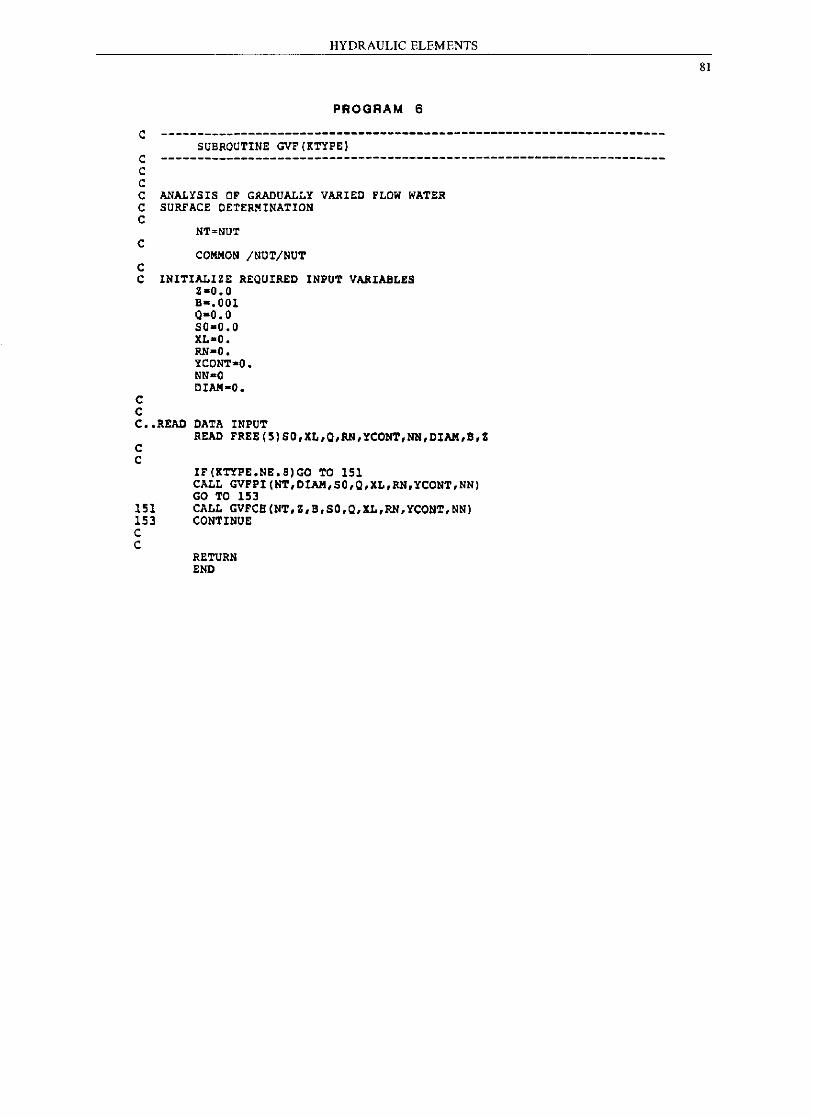
HYDRAULIC ELEMENTS
PROGRAM 6
C ---------------------------------------------------------------------SUBROUTINE GVF(KTYPEl C ---------------------------------------------------------------------C C C ANALYSIS OF GRADUALLY VARIED FLOW WATER C SURFACE DETERMINATION C
NT'NUT C
COMIION /NOT/NOT C C INITIALIZE REQUIRED INPUT VARIABLES
Z-O.O
C C
B-.OOl 0-0.0 50-0.0 XL-O. RN-O. YCONT-O. NN-O DlAM-O.
C •• READ DATA INPUT
C C
READ FREE(5lS0,XL,O,RN,YCONT,NN,DIAM,B,Z
IF(KTYPE.NE.B)GO TO 151 CALL GVFPI(NT,DIAM,SO,O,XL,RN,YCONT,NN) GO TO 153
151 CALL GVFCH(NT,Z,B,SO,O,XL,RN,YCONT,NN) 153 CONTINUE C C
RETURN END
81
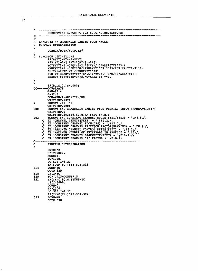
82
HYDRAULIC ELEMENTS
c ---------------------------------------------------------------------SUBROUTINE GVFCB(NT,Z,B,SO,Q,XL,RN,YXNT,NN}
c ---------------------------------------------------------------------C C ANALYSIS OP GRADUALLY VARIED PLOW WA~ER C SURFACE DETERMINATION C
COKKON/NU~P/NUTP,ISV C C FUNCTION O~PINITIONS
C C
AREA(YY)-YY*(B+Z*YY) PER(YY)-B+2.*YY*SQRT(1.+Z*Z) YCTP(YY)-1.-o*Q*(B+2.*Z*YY)/(o*AREA(YY) **3.) YNMP(YY)-I.-o*Q*CON/(AREA(YY)**l.llll/PER(YY)**1.l333) DL(YY)-YCTP(YY)/(YNMF(YY)*SO) FPM(YY)-GAM*(YY*YY*(S*.5+Z*YY/3.)+Q*Q/(o*AREA(YY») ENEROY(YY)-YY+Q*Q/(2.*G*ARSA(YY) **2.)
IF(B.LE.O.)S-.OOOl CC------CONSTANTS
GAM-02.4 G-n.l CON-(RNll.486)**2./SO WRI~E (NT, 187)
5 FORMAT(15('-'» WRITE (NT,200)
200 FORMAT(5X,'GRADOALLY VARIED FLOW PROFILE INPUT INFORMA~IONI') WRITE (NT,5) WRI~E(NT,202)SD,XL,Q,RN,YXNT,NN,B,Z
202 FORMAT(5X,'CONSTANT CHANNEL SLOPE(FEET/FEET) • ',F8.6,I, C 5X,'CHANNEL LENGTH(FEE~) - ',r12.2,I, C SX,'CONSTANT CHANNEL FLOW(CPS) • ',112.2,/, C 5X,'CONSTANT CBANNEL FRICTION FACTOR(MANNING) • ',F8.6,1, C 5X,'ASSUMED CHANNEL CON~ROL DEPTH(FEET) • ',F8.2,I, C 5X,'MAXIMUM NUMBER OF INTERVALS IN PROFILE· ',16,1, C SX,'CONS~ANT CHANNEL SASEWIDTB(PEET) - ',FI0.2,I, C 5X,'CONS~ANT CBANNEL 'Z' FACTOR - ',F10.4)
C-----------------------------------------------------------C PROFILE DETERMINATION C
NN-NN*2 UPIT-5000. DOWN-O. YC-IOOD. DO 520 1-1,22 IF(¥CTF(YC»514,521.515
514 DOWN-YC GCTO 520
515 UPIT-YC 520 YC-(UPIT+OOWN) *.5 521 IF(Y~NT.EQ.O.)YKN~~YC
UPI~~5000.
DOWN-O. YN-IOOO. DO 530 1-1,22 IF(YNMF(YN»523.531.524
523 OOWN-YN GOTO 530
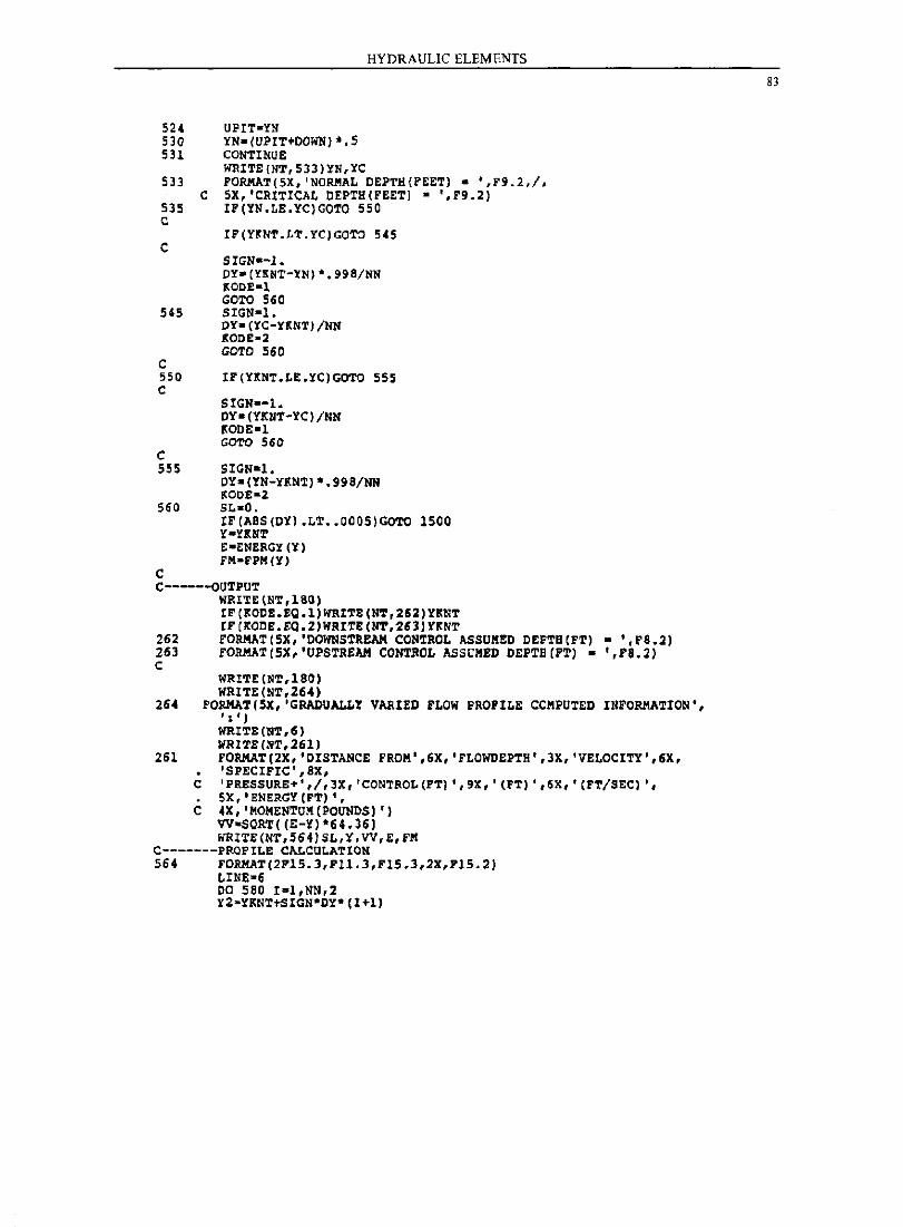
HYDRAULIC ELEMENTS
524 UPIT~,{!I
530 YNo(UPIT+OOWN) *,5 531 CONTINUE
~ITE{NT,533)YN,YC 533 FORMAT(5X, 'NORMAL OEPTH{FEET) 0 ',P9.2,/,
C 5X,'CRITICAL OEPTH(PEET) - ',F9,2) 535 IF(YN,LE,YC)GOTO 550 C
C IF(YKNT.LT.YC)GOTO 545
SIGN--l. DYo(YKNT-YN)·.99S/NN I<OOE-l GOTO 560
545 SIGN-l.
C
DY-(YC-YKNT)/NN 1':00£-2 GOTO 560
550 IF{YKNT.LE.YC)GOTO 555 C
C
SIGN--l. OY- (YKIIT-ICj /NN I<OOE-l GOTO 560
555 SIGN-l. DY-(YN-YKNT)*.99S/NN 1<00£-2
560 SL-O.
c
IF(ABS(OY) .LT •• 0005)GOTO 1500 YoUNT E-ENERGY(Y) FM-PPM(Y)
C-----oUTPUT WRITEINT,18Q) IF(KOCE.EQ.l)~ITE(NT,262)YKNT IF (KOCE.EQ,2)liRITE(NT,261)YKNT
262 rORMAT(5X,'COWNSTREAH CONTROL ASSUMEC DEPTB(FT) - ',FS •• ) 263 rORMAT(5X,'UPSTREAH CONTROL ASSOMED DEPTB(PT) - ',P8.2) c
WRITE (NT,ISO) WRITE (NT,264)
264 FORMAT(5X,'GRADUALLY VARIED FLOW PROFILE COMPUTED INFORMATION', I : ' » WRITE (NT,6) WRITE(NT,.61)
261 FORMAT(2X,'OISTANCE PROM',6X,'PLOWDEPTH',3X, 'VELOCITY ',6X, 'SPECIFIC·,ax,
C 'PRESSURE+',/,3X,'CONTRO~(FT) ',9K, '(PT)',6K, '(FT/SEC) " • 5X,'ENERGY(FT)', C 4X, 'MOMENTUlI(POUNDS) ')
VV·SQRT«E-~)·64.36) WRIT~(NT,S64)SL,y,VV,E,fH
c-------PROFI~E CA~CULATION
564 FORMAT(2F15.3,Fll,3,F15.3,2X,FJ5.2) LINE~6 DO 580 I~1,NN,2 y2-YKNT+SIGN*CY*(I+l)
83
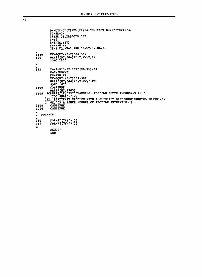
84
C
HYDRAULIC ELEMENTS
DX_DY*(DL(Y)+DL(Y2)+4.*DL(YINT+SIGN*I*DY»/3. SL-SL+DX IP(SL.GT.XL)GOTO 582 Y-Y2 E-ENERGY(Y) FH-PI'H(Y) IP(I.EQ.NN-l.AND.SL.LT.O.)SL-XL
1580 VV-SQRT«E-Y)*64.36) 580 WRITE(NT,564)SL,Y,VV,E,FH
C C
GOTO 1000
582 Y-Y2-SIGN·Z.·DY*(SL-XL)/DX E-ENERGY(Y) FH-FPII(Y) VV-SQRT«E-Y)·64.36) WRITE(NT.564)XL.Y,VV,E.PII GCTO 1600
1500 CONTINUE WRITE (NT,1505)
1505 FORMAT(/lX,'·····WARNING. PROFILE DEPTB INCREIIENT IS '. • 'TOO SHALL. ',j, C6X,'REATTEIIPT PROBLEII WITB A SLIGHTLY DIFFERENT CONTROL DEPTH',j, C 6X.'OR A FEWER NUIIBER OF PROFILE INTERVALS.')
1600 CONTINUE 1000 CONTINUE C C FORMATS C 180 FORMAT(76('·'») 187 FORMAT(76('·') C
RETURN END
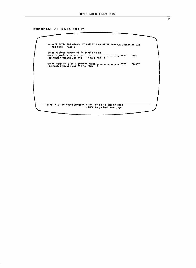
HYDRAULIC ELEMENTS
PROGRAM 7: DATA ENTRY
---oATA ENTRY FOR GRAOUALLY VARIED 'LOW WATER SURFACE DeTER~lNATI0N FOR PIPE--f'AGE Z
Enter •• xieu. nunber of intervals to bt u3ed ~n profi le ............................................ ==*> "NN" ,All.OWASCE VACUES ARE [10 J TO [1000 J
Enter CQnstant pi~e diam.t.rCINCHESJ •••••••••••••••• z=_> :ALLOWASLE VALUES ARE [3] TO (24Q l
TYPE; EXIT to le ..... pragr.a ; TOP to go to top of pa~e ; e.l.CK to go back ont pag,t
"orAM"
85
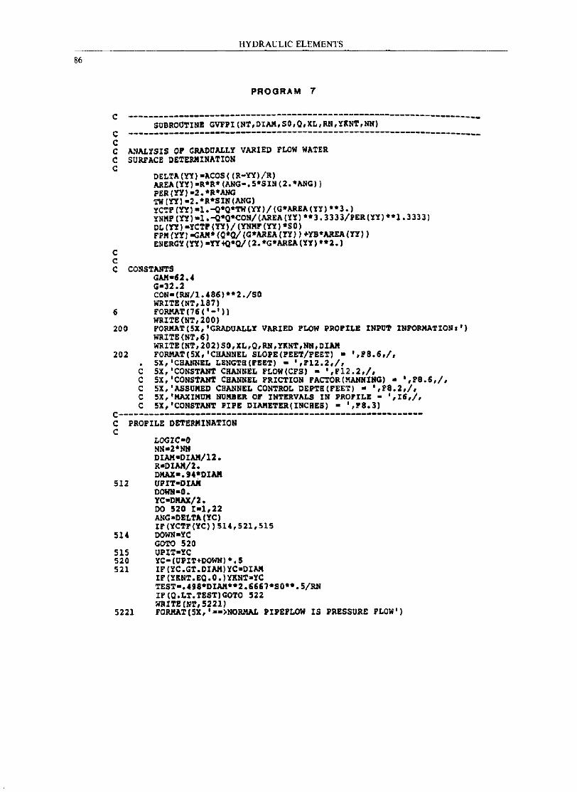
86
HYDRAULIC ELEMENTS
PROGRAM 7
C ---------------------------------------------------------------------SUBROOTINB GVFPI(NT,OIAM,SO,O,XL,RN,YINT,NN) C ---------------------------------------------------------------------C C ANALYSIS or GRADUALLY VARIED FLOW WATER C SURFACE DETERMINATION C
C C
OELTA(YY)-ACOS«R-YY)!R) AREA(YY)-R*R*(ANG-.5*SIN(2.*ANG» PER(YY,-2.*R*ANG TW(YY'-2.*R*SIN(ANG) YCTP(YY,-1.-o*O*TW(YY)!(GOAREA(YY) **3.) YNMP(YX)-1.-o*O*CON/(AREA(yy)*o3.3333/PER(yy)*o1.3333) OL(YY)-YCTP(YY)/(YNMF(YY)*SO) FPM(YX)aCAM*(O*O/(G*AREA(YX»+YBoAREA(YY) ENERGY (YX)-YY+QoO/(2.oG*AREA(YX)·*2.)
C CONSTANTS GAM-n •• G-32.2 CON-(RN/1 •• 86)·*2./S0 WRITE(NT,187)
6 FORMAT(16('-'I) WRITE (NT,200)
200 PORMAT(5X,'GRADOALLY VARIED FLOW PROFILE INPUT INFORMATION,') WRITE (NT.6) WRITE(NT,202)SO,XL,O,RN,YINT,NN,OIAM
202 FORMAT (5X, 'CHANNEL SLOPE(FEET/FEET) - ',p8.6./, 5X,'CBANNEL LENGTB(FEET) - ',F12.2.1.
C 5X,'CONSTANT CHANNEL FLOW(CFS) - ',F12.2,/, C 5X,'CONSTANT CBANNEL FRICTION PACTOR(MANNING) - '.F8.6,I, C 5X,'ASSUMED CHANNEL CONTROL DEPTB(PEET) - ',F8.2,1. C 5X,'MAXIMOM NUMBER OF INTERVALS IN PROFILE - ',16,1, C 5X,'CONSTANT PIPE DIAMETER(INCBES) - ',Fa.3)
C-----------------------------------------------------------C PROPILE DETERMINATION C
LOGIC-O NN-2*NN DIAM-DIAM/12. R-DIAN/l. DMAX-.94*DIAN
512 UPIT-DIAK DOWH-O .. YC-DMAX/2. DO 520 1-1,22 ANG-DELTA (YC) IF(YCTF(YC»514,521,515
514 DOWN-YC GOTe 520
515 UPIT-YC 520 YC-(OPIT+DOWN) *.5 521 IF (YC.GT.DIAN)YC-DIAM
IP(YKNT.EO.O.)YKNT·YC TEST-.49a*DIAM*o2.6667*SO**.5/RN IF(O.LT.TEST)GOTO 522 WRITE (Nt,5221)
5221 FORMAt(5X,'·-)NORMAL PIPEFLOW IS PRESSURE FLOW',
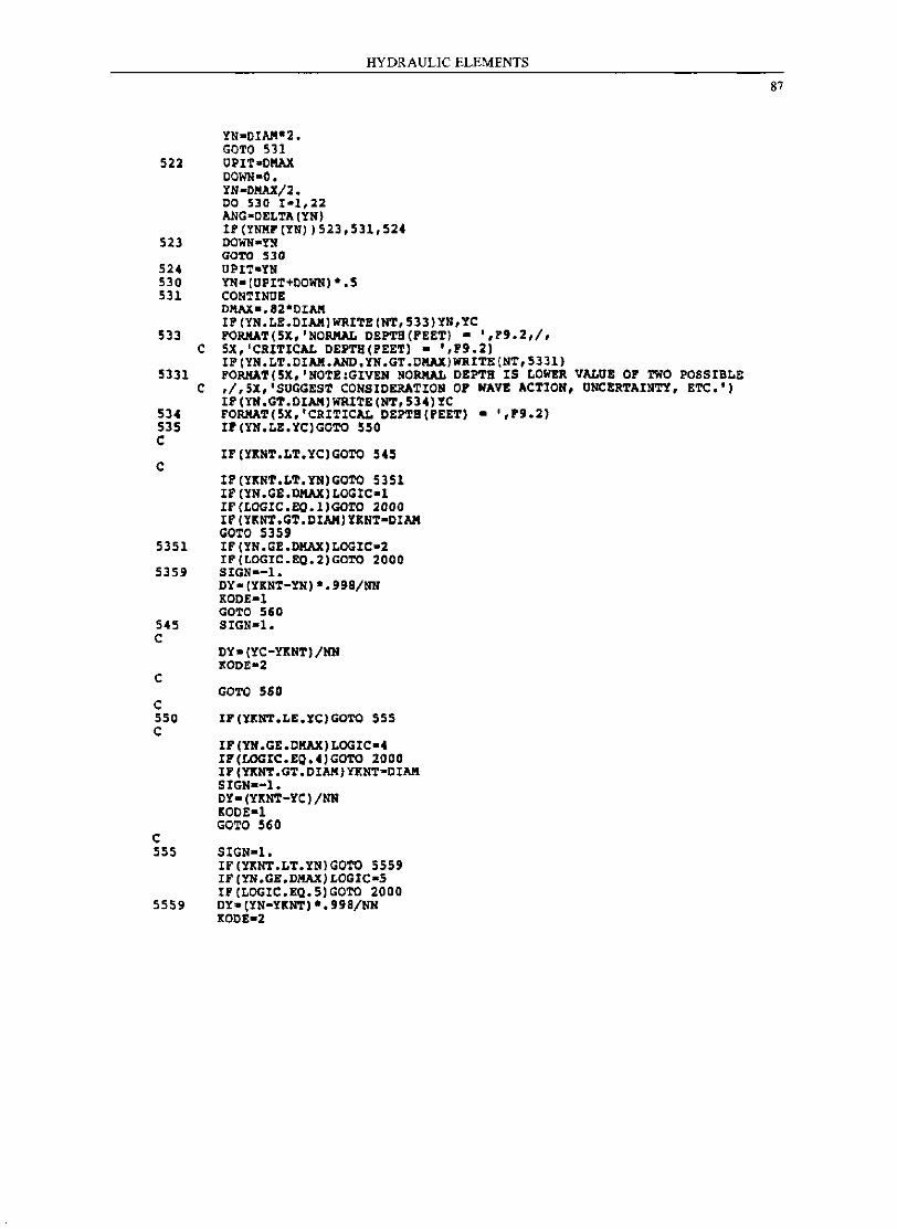
YN-DIAII"2. GOTO 531
HYDRAULIC ELEMENTS
522 UPIT-OMAX
523
524 530 531
533 C
5331 C
534 535 C
C
DOWN-D. YN-OMAX/2. 00 530 1-1,22 ANG-OELTA(YN) IP(YNMP(YN))523,531,524 DOWN-Yll GOTO 530 UPIT-YN YN-(UPIT+OOWN)-.5 CONTINUE Dl'lAX-.82*DIAM IP(YN.LE.DIAII)WRITE(NT,533)YN,YC PORMAT(5X.'NORMAL DEPTB(PEET) • ',P9.2,/, 5X. 'CRITICAL DEPTII(PEETI • '.F9.21 IP(YN.LT.DIAII.AND.YN.GT.OMAX)WRITE(NT,5331) PORMAT(5X.'NOTE.GIVEN NORMAL DEPTB IS LOWER VALUE or TWO POSSIBLE ,/,SX.'SUGGEST CONSIDERATION OP WAVE ACTION, UNCERTAINTY, ETC.') IF (YN.GT.DIAIII WRITE (NT. 5341 YC FORMAT(5X, 'CRITICAL DEPTB(PEETI • ',P9.2) IP(YN.LE.YC)GOTO 550
IF(YKNT.LT.YC)GOTO 545
IP(YKNT.LT.YN)GOTO 5351 IF (YN.GE.DMAXILOGIC-l IF(LOGIC.EQ.lIGOTO 2000 IF (YKNT.GT.DIAMIYENT-DIAM GOTO 5359
5351 IF (YN.GE.DMAX)LOGIC-2 IF(LOGIC.EQ.2)GOTO 2000
5359 SIGN--l. DY-(YKNT-YN) ".99B/NN KODE-l GOTO 560
545 SIGN-I. C
C
C
DY- (YC-YltNT) /NN KODE-2
GOTO 560
550 IP(YKNT.LE.YC)GOTO 555 C
C
IP(YN.GE.DMAX)LOGIC-. IP(LOGIC.EQ.4)GOTO 2000 IF (YltNT.GT.DIAII)YKNT-OIAII SIGN--l. DY- (YitNT-YCl/NN KOOE-l GOTO 560
555 SIGN-I. IF(YKNT.LT.YN)GOTO 5559 IF (YN.GE.DMAX)LOGIC-S IF(LOGIC.EQ.51GOTO 2000
5559 OY-(YN-YKNTl".99B/NN 11:00£-2
87
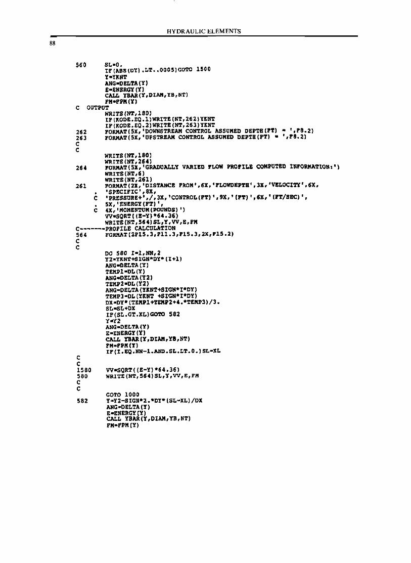
88
560
HYDRAULIC ELEMENTS
SL-O. IF(ABS(OY).LT •• 0005)GOTO 1500 Y-UNT ANG-DBLTA(Y) E-ENERGY(Y) CALL YBAR(y,DIAR,YB,NT) FM-Pl'M(Y)
C OUTPUT
262 263 C C
WRITE(NT,l80) IP(~ODE.EQ.lIWRIT£(NT,262)Y~NT IF(KODE.EQ.2)WRITE(NT,263)YKNT FORMAT(5X,'DOWNSTREAR CONTROL ASSOMED DEPTH(PT) - ',PS.2) FORMAT (5X, 'UPSTREAM CONTROL ASSUMED DEPTB(PT) - ',PS.2)
WRITE (NT ,180) WRITE (NT,254)
264 FORMAT(5X,'GRADOALLY VARIED PLON PROfILE COMl'UTED INPORMATION,') IIIIITS(NT,6) IIIIITS (NT, 2U)
261 PORMAT(2X,'DISTANCE PROM',6X,'PLOWDEPTB',3X,'V£LOCITY',6X, • 'SPECIFIC' ,8X, C 'PRESSORE+',/,3X,'CONTROL(PT)',9X,'(PT)',6X,'(PT/SEC), , • 5X, 'ENERGY CPT) " C 4X,'MOMENTOMCPOOHOS) ')
VV-SQRTC(E-Y)*64.J6) WRITECNT,564)SL,Y,VV,E,PM
C-------PROPILE CALCULATION 564 FORMATC2FI5.3,Pll.3,FlS.3,2X,PlS.2) C C
C C
DO 580 r-I,NN,2 YZ-YKNT+SIGN*OY*CI+I) ANG-DELTA (Y) TEMPI-DL(Y) ANG-DELTACY2) TEMl'2-DL(Y2) ANG-DELTACYBNT+SIGN*I*DY) TEMP3-DL(YBNT +SIGN*I*DY) DX-DY*(TEMPl+TEMl'2+4.*TEMl'3)/3. SL-SL+DX IF(SL.GT.XL)GOTO 582 Y-y2 ANG-DELTACY) E-ENERGY CY) CALL DAR(Y,DIAM,n,NT) FM-rPMCY) IFCI.EQ.NN-I.AND.SL.LT.O.)SL-XL
1580 VV-SQRT«(E-Y)*64.36) 580 WRITE(NT,564)SL,Y,VV,E,FM C C
GOTO 1000 5S2 Y-Y2-SIGN°2.*DY*CSL-XL)/DX
ANG-DELTACY) S-ENERGY(Y) CALL YBAR(Y,DIAM,YB,NT) FM-PPM(Y)
1000
1500
1505
2000
2005
2100 C
HYDRAULIC ELEMENTS
VV.SQRT( (E-lC) ·54,36) WRITE(NT,564)XL,Y,VV,E,FM CONTINUB GOTO 2100 CONTINUB WJtITE(NT.1505) FORKAT(/lX,······WARNING,PROFILE DEPTH INCRE~ENT IS TOO SMALL.',
C/6X,'REATTEMPT PROBLEM WITa A SLIGHTLY DIFFERENT CONTROL DEPTH',I. C 6X,'OR A FEWER NUMBER OF PROFILE INTERVALS,')
GOTO 2100 CONTINUE WRITE(NT,6) HIUTE(NT,200S) FORHAT(5X,'PLOW PROFILB OEPTBS ARB GREATBR THAN ,82·0IAME~ER,·.
C I,SX,'SUGGEST CONSIDERATION or SEALED FLOW IN THIS REACH DUE TO',I, C 5X,' WAVE ACTION, UNCERTAIN1'Y, ETC,')
CONTINUE
C FORIIATS C 180 187 C
FORIIAT (76 ( '.'» FOlUIAT (76 ( '.'))
RETURN IlNl)
89
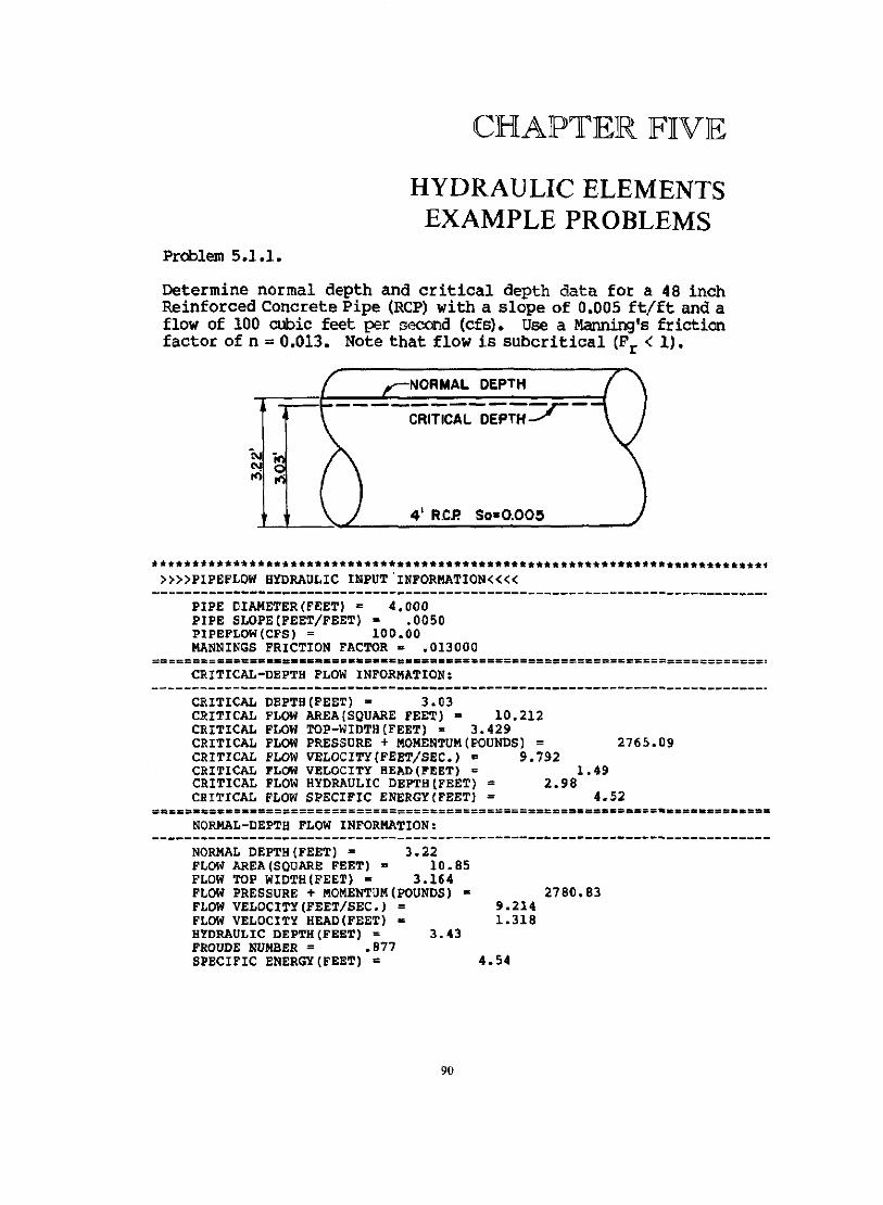
CHAPTER FIVE
HYDRAULIC ELEMENTS EXAMPLE PROBLEMS
Problem 5.1.1.
Determine normal depth and critical depth data for a 48 inch Reinforced Concrete Pipe (RCP) with a slope of 0.005 ft/ft and a flow of 100 cubic feet per second (cfs). Use a Manning's friction factor of n = 0.013. Note that flow is subcritical (F r < 1).
NORMAL DEPTH
-----------;--CRITICAL DEPTH--
4' R,CP' So·O.OO~
.*************.*************** •• ******************* ••• *********************1 »»PIPEFLOW HYDRAULIC INPUT'INFORMATION««
----------------------------------------------------------------------------PIPE DIAMETER (FEET) = 4.000 PIPE SLOPE(FEET/FEET). .OOSO PIPEFLOW(CFS) = 100.00 MANNINGS FRICTION FACTOR - .013000
CRITICAL-DEPTH FLOW INFORMATION:
CRITICAL DEPTH(PEET) - 3.03 CRITICAL FLOW AREA (SQUARE FEET) D 10.212 CRITICAL FLOW TOP-WIDTH(FEET) = 3.429 CRITICAL FLOW PRESSURE + MOMENTUM(POUNDS) = 2765.09 CRITICAL FLOW VELOCITY(FEET/SEC.). 9.792 CRITICAL FLOW VELOCITY HEAO(FEET) = 1.49 CRITICAL FLOW HYDRAULIC DEPTH(FEET) = 2.98 CRITICAL FLOW SPECIFIC ENERGY(FEET) = 4.52
=~sc= •• = •• = •• =======================================.== •• =~.== •• == ••• ==.===. NORMAL-DEPTH FLOW INFORMATION:
NORMAL DEPTH(FEET) = 3.22 FLOW AREA(SOUARE FEET) = 10.85 FLOW TOP WIDTH(FEET) - 3.164 FLOW PRESSURE + MOMENTUM(POUNDS) - 2780.B3 FLOW VELOCITY(FEET/SEC.) = 9.214 FLOW VELOCITY HEAD(FEET) K 1.318 HYDRAULIC DEPTH(FEET) = 3.43 FROUDE NUMBER = .B77 SPECIFIC ENERGY (FEET) ~ 4.54
90
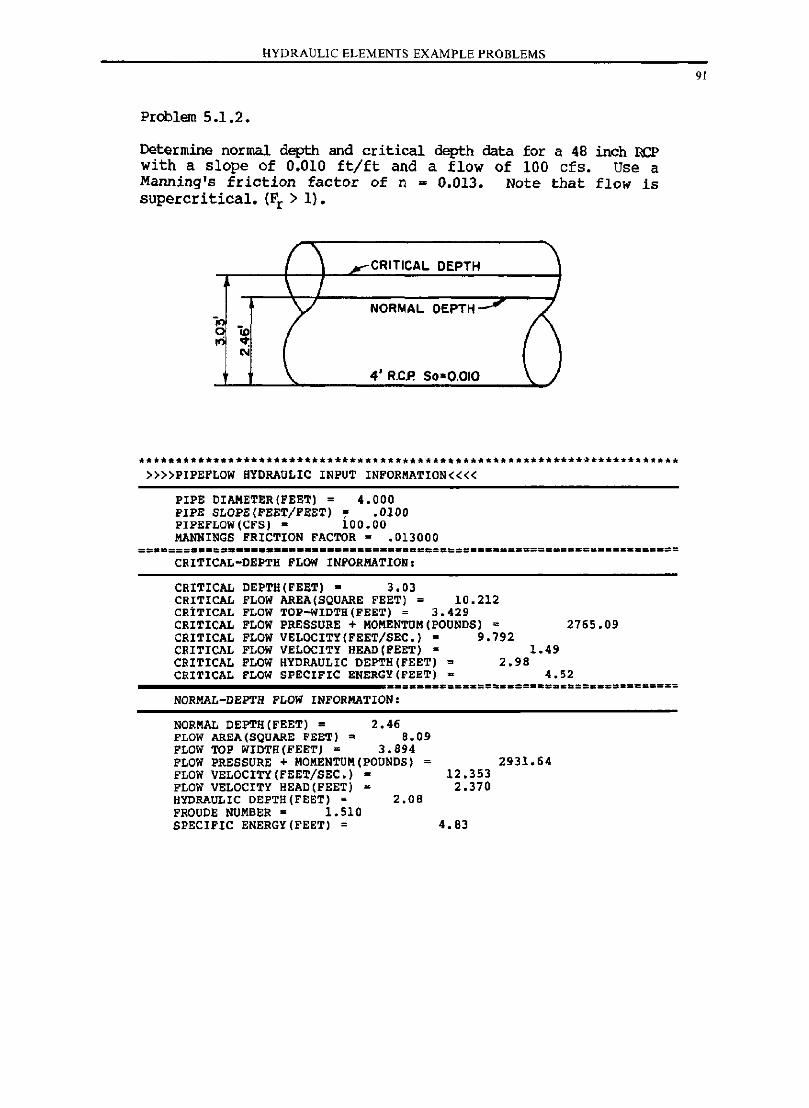
HYDRAULIC ELEMENTS EXAMPLE PROBLEMS
Proolem 5.1.2.
Determine normal depth and critical depth data for a 48 inch BCP with a slope of 0.010 ft/ft and a flow of 100 cfs. Use a Manning's friction factor of n = 0.013. Note that flow is supercritical. (Fr > 1).
CRITICAL DEPTH
NORMAL DEPTH
4' R.CP. $0-0.010
** ••• *** •• *** ••••••• *** •• ** •• ** •••••• ** •••••••• * •••••• * •••• ~ •••• ***.* ••• »»PIPEFLOW HYDRAULIC INPUT INFORMATION««
PIPE DIAMETER(FEET) = 4.000 PIPE SLOPE(FEET/FEET) ~ .0100 PIFEFLOW(CFS) = 100.00 MANNINGS FRICTION FACTOR = .013000
CRITICAL-DEPTH FLOW INFORMATION:
CRITICAL DEPTH(FEET) • 3.03 CRITICAL FLOW AREA (SQUARE FEET) = 10.212 CRITICAL FLOW TOP-WIDTH(FEET) = 3.429 CRITICAL FLOW PRESSURE + MOMENTUM(POUNDS) = 2765.09 CRITICAL FLOW VELOCITY(FEET/SEC.) ~ 9.792 CRITICAL FLOW VELOCITY HEAD(FEET) = 1.49 CRITICAL FLOW HYDRAULIC DEPTH(FEET) = 2.98 CRITICAL FLOW SPECIFIC ENBRGY(FEET) • 4.52
NORMAL-DEPTH FLOW INFORMATION:
NORMAL DEPTH(FEET) = 2.46 FLOW AREA (SQUARE FEET) = 8.09 FLOW TOP WIDTH(FEET) = 3.894 FLOW PRESSURE + MOMENTUM(POUNDS) = 2931.64 FLOW VELOCITY(FEET/SEC.) • 12.353 FLOW VELOCITY HEAD(FEET) = 2.370 HYDRAULIC DEPTB(FEET) = 2.08 FROUDE NUMBER· 1.510 SPECIFIC ENERGY(FEET) = 4.83
91
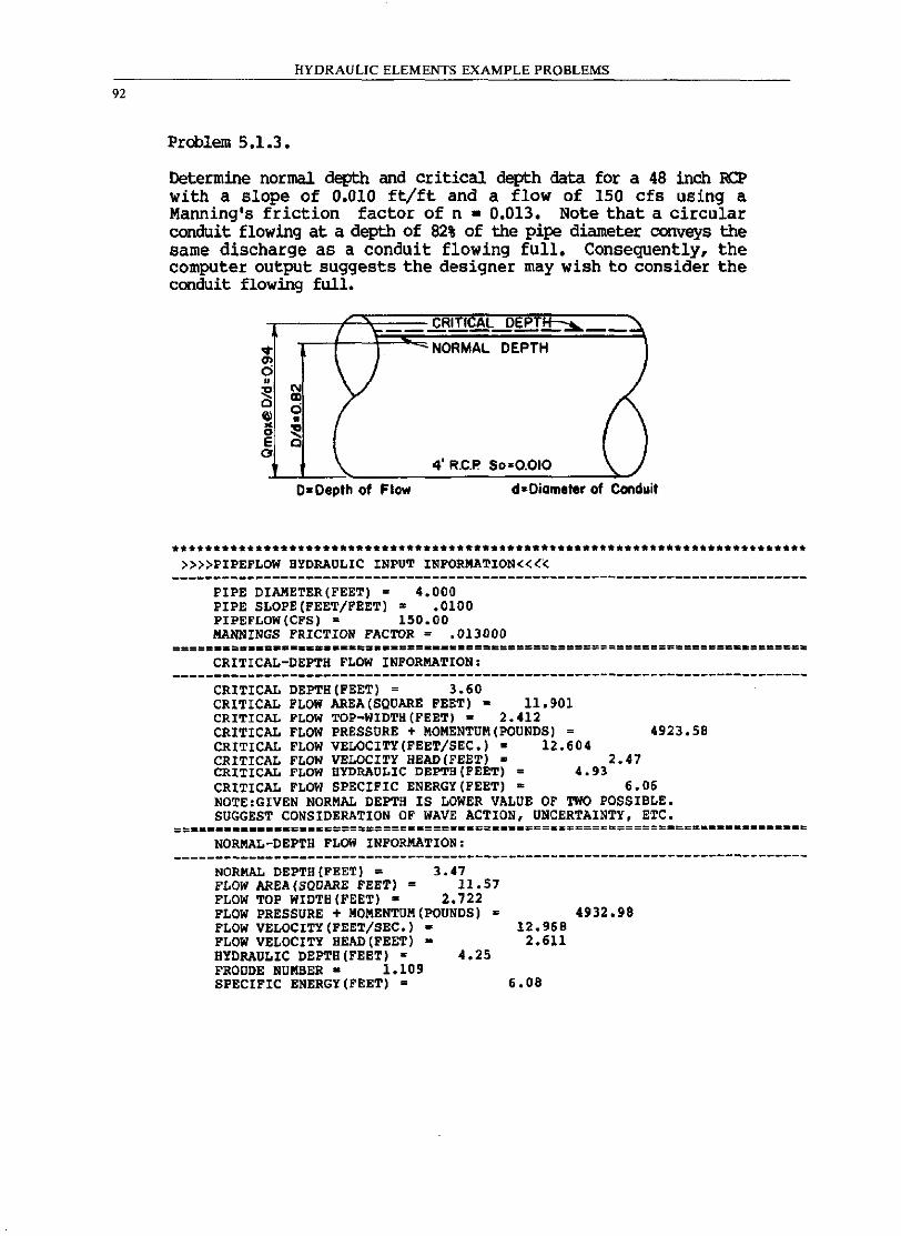
92
HYDRAULIC ELEMENTS EXAMPLE PROBLEMS
Problem 5.1.3.
Determine normal depth and critical depth data for a 48 inch RCP with a slope of 0.010 ft/ft and a flow of 150 cfs using a Manning's friction factor of n = 0.013. Note that a circular conduit flowing at a depth of 82% of the pipe diameter conveys the same discharge as a conduit flowing full. Consequently, the computer output suggests the designer may wish to consider the conduit flowing full.
.... <1> o »
" 0 E o
'" ell d • ~ Q
"-
CRITf~L Dill!:!:::"::!... -~ NORMAL DEPTH
4' R.C.P' $0=0.010 \. )
D-Depth of Flow d = Diameter of Conduit
********.*************.*.*************************************************** »»PIPEFLOW HYDRAULIC INPUT INFORMATION««
----------------------------------------------------------------------------PIPE DIAMETER(FEET) = 4.000 PIPE SLOPE(FEET/FEET)' .0100 PIPEFLOW(CFS) = 150.00 MANNINGS FRICTION FACTOR = .013000
CRITICAL-DEPTH FLOW INFORMATION:
CRITICAL DEPTH(FEET) = 3.60 CRITICAL FLOW AREA (SQUARE FEET) = 11.901 CRITICAL FLOW TOP-WIDTH(FEET) = 2.412 CRITICAL FLOW PRESSURE + MOMENTUM(POUNDS) = 4923.58 CRITICAL FLOW VELOCITY(FEET/SEC.)· 12.604 CRITICAL FLOW VELOCITY HEAD (FEET) • 2.47 CRITICAL FLOW HYDRAULIC DEPTH(FEET) = 4.93 CRITICAL FLOW SPECIFIC ENERGY(FEET) = 6.06 NOTE,GIVEN NORMAL DEPTH IS LOWER VALUE OF TWO POSSIBLE. SUGGEST CONSIDERATION OF WAVE ACTION, UNCERTAINTY, ETC.
==_== ••• _.c ... ===.====~==============:========_====================-======== NORMAL-DEPTH FLOW INFORMATION:
----------------------------------------------------------------------------NORMAL DEPTB(FEET) = 3.'7 FLOW AREA (SQUARE FEET) = 11.57 FLOW TOP WIDTH(FEET)· 2.722 FLOW PRESSURE + MOMENTUM(POUNDS) s 4932.98 FLOW VELOCITY (FEET/SEC.) - 12.968 FLOW VELOCITY HEAD (FEET) = 2.611 HYDRAULIC DEPTH(FEET) = 4.25 FROUDE NUMBER • 1.109 SPECIFIC ENERGY (FEET) = 6.08
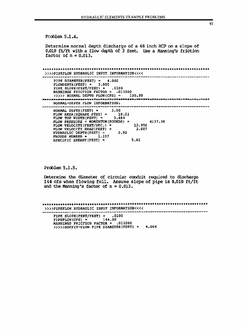
HYDRAULIC ELEMENTS EXAMPLE PROBLEMS
Problem 5.1.4.
Determine normal depth discharge of a 48 inch RCP on a slope of 0.010 ft/ft with a flow depth of 3 feet. Use a Manning's friction factor of n = 0.013.
***.**.*********************************************** •••• * ••• _ •• _-_._-----»»PIPEFLOW HYDRAULIC INPUT INFORMATION««
FIFE DIAMETER(FEET) = 4.000 FLOWDEPT8(FEET) s 3.000 PIPE SLOPE(FEET/FEET) = .0100 MANNINGS FRICTION FACTOR = .013000 »»> NORMAL DEPTH FLOW(CPS) = 130.99
NORMAL-DEFTH FLOW INFORMATION.
NORMAL DEPTH(FEET) • 3.00 FLOW AREA (SQUARE FEET) = 10.11 FLOW TOP WIDTH(FEET) = 3.464 FLOW PRESSURE + KOMENTUM(POUNDS) = 4137.36 FLOW VELOCITY (FEET/SEC.) = 12.956 FLOW VELOCITY READ (FEET) = 2.607 HYDRAULIC DEPTB(FEET) = 2.92 FROUDE NUMBER = 1.337 SPECIFIC ENERGY(FEET) a 5.61
Problem 5.1.5.
Determine the diameter of circular conduit required to discharge 144 cfs when flowing full. Assume slope of pipe is 0.010 ft/ft and the Manning's factor of n = 0.013 •
. _*----------*.- .. -----.. -._.---_ .... __ .. ---..... -... -***-. __ •• _ ••• _._-_.-»»PIPEFLOW HYDRAULIC INPUT INFORMATION««
--------------------------------------------------------------------------PIPE SLOPE(FEET/FEET) = .0100 PIPEFLOW(CFS) = 144.00 MANNINGS FRICTION FACTOR = .013000 »»>SOFFIT-FLOW PIPE DIAMETER(FEET) 4.004
93
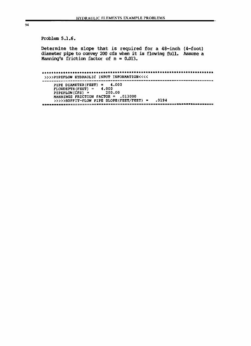
94
HYDRAULIC ELEMENTS EXAMPLE PROBLEMS
Problem 5.1.6.
Determine the slope that is required for a 48-inch diameter pipe to convey 200 cfs when it is flowing full. Manning's friction factor of n = 0.013.
(4-foot) Assume a
**********************************************.***.*.******************.* »»PIPEFLOW HYDRAULIC INPUT INFORMATION««
-------------------------------------------------------------------------PIPE DIAMETER(FEET) = 4.000 FLOWDEPTH(FEET) = 4.000 PIPEFLOW(CFS) = 200.00 MANNINGS FRICTION FACTOR = .013000 »»>SOFFIT-FLOW PIPE SLOPE(FEET/FEET) • .0194
== •••• ~==========================================~=.===== •••••••••••••• ==
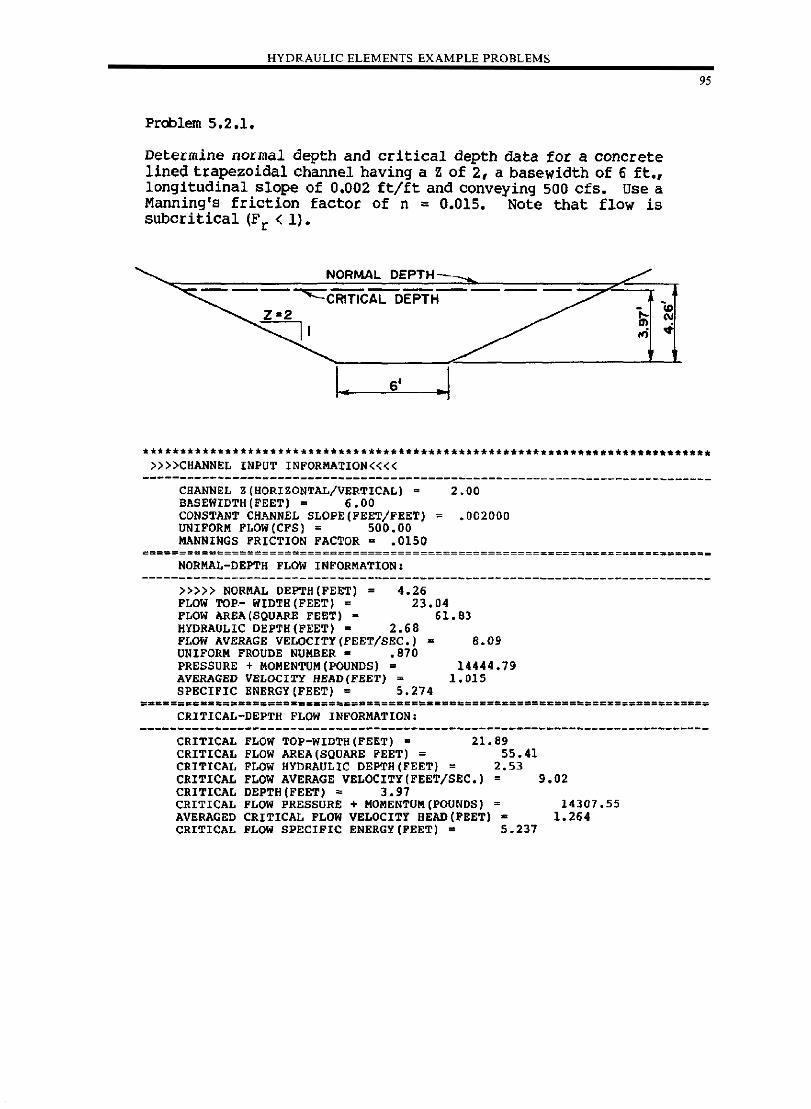
___ ____ . HYDRAULIC ELEMENTS EXAMPLE PROB.:L:::E"'M"'S'-______ . __ _
Problem 5.2.1.
Determine normal depth and critical depth data for a concrete lined trapezoidal channel having a Z of 2, a basewidth of 6 ft., longitudinal slope of 0.002 ft/ft and conveying sao cfs. Use a Manning's friction factor of n : 0.015. Note that flow is subcritical (F r < 1).
NORMAL DEPTH
---~CRITICAL DEPTH------
Z-2
I • 6' .1
9S
•• * •••••• _._ •••••• *.-............ _ ......... *. __ • __ ._ •• _ •••• _----._--*_ ... _--»»CHANNEL INPUT INFORMATION««
----------------------------------------------------------------------------CHANNEL Z(HORIZONTAL/VERTICAL) = 2.00 BASEWIDTH(FEET) = 6.00 CONSTANT CHANNEL SLOPE(FEET/FEET) ~ .002000 UNIFORM FLOW(CFS) = 500.00 MANNINGS FRICTION FACTOR· .0150
==========================================================~==========:=====-
NORMAL-DEPTH FLOW INFORMATION:
»»> NORMAL DEPTH(FEET) = 4.26 FLOW TOP.- WIDTH (FEET) = 23.04
61.83 FLOW AREA (SQUARE FEET) -HYDRAULIC DEPTH(FEET) = 2.68 FLOW AVERAGE VELOCITY(FEET/SEC.) UNIFORM FROUDE NUMBER - .870 PRESSURE + MOMENTUM (POUNDS) = AVERAGED VELOCITY HEAD(FEET) ~
SPECIFIC ENERGY(FEET) = 5.274
CRITICAL-DEPTH FLOW INFORMATION:
B.09
14444.79 1.015
CRITICAL FLOW TOP-WIDTH(FEET) • 21.89 CRITICAL PLOW AREA (SQUARE FEET) = 55.41 CRITICAL FLOW HYDRAULIC DEPTH(FEET) = 2.53 CRITICAL FLOW AVERAGE VELOCITY(FEET/SEC.) = 9.02 CRITICAL DEPTH(FEET) = 3.97 CRITICAL FLOW PRESSURE + MOMENTUM[POUNDS) = 14307.55 AVERAGED CRITICAL FLOW VELOCITY BEAD(PEET) • 1.264 CRITICAL FLOW SPECIFIC ENERGY(PEET) = 5.237
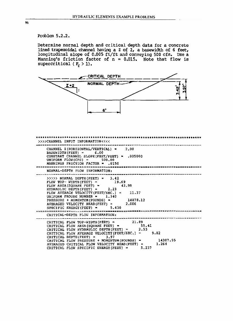
%
HYDRAULIC ELEMENTS EXAMPLE PROBLEMS
Problem 5.2.2.
Determine normal depth and critical depth data for a concrete lined trapezoidal channel having a Z of 2, a basewidth of 6 feet, longitudinal slope of 0.005 ft/ft and conveying 500 cfs. Use a Manning's friction factor of n = 0.015. Note that flow is supercritical ( Fr > 1).
NORMAL DEPTH :;..;;;r
I. 6' .I
****************************************************** ********************** »»CHANNEL INPUT INFORKATION««
CHANNEL Z(HORIZONTAL/VERTICAL) = 2.00 BASEWIDTH(FEET) = 6.00 CONSTANT CHANNEL SLOPE(FEET/FEET) = .005000 UNIFORM FLOW(CFS) = 500.00 KANNINGS FRICTION FACTOR = .0150
========================================================a=c================= NORMAL-DEPTH FLOW INFORMATION:
»»> NORMAL DEPTH{FEET) = FLOW TOP- WIDTH(FEET) = FLOW AREA(SQUARE FEET) =
3.42 19.69
43.99 HYDRAULIC DEPTH{FEET) = 2.23 FLOW AVERAGE VELOCITY{FEET/SEC.) = UNIFORM FROUDE NUMBER = 1.340 PRESSURE + MOMENTUM{POUNDS) = AVERAGED VELOCITY HEAD(FEET) = SPECIFIC ENERGY(FEET) = 5.430
11.37
14878.12 2.006
=================================~ •••• ====-•• =============================== CRITICAL-DEPTH FLO,I INFORMATION:
----------------------------------------------------------------------------CRITICAL FLOW TOP-WIDTH(FEET) = 21.89 CRITICAL FLOW AREA (SQUARE FEET) = 55.41 CRITICAL FLOW HYDRAULIC DEPTH(FEET) = 2.53 CRITICAL FLOW AVERAGE VELOCITY(FEET/SEC.) = 9.02 CRITICAL DEPTH(FEET) = 3.97 CRITICAL FLOii' PRESSURE + MOMEN,UH (POUNDS) - 14307.55 AVERAGED CRITICAL FLOW VELOCITY HEAD(FEET) 1.264 CRITICAL FLOW SPECIFIC ENERGY(FEET) = 5.237
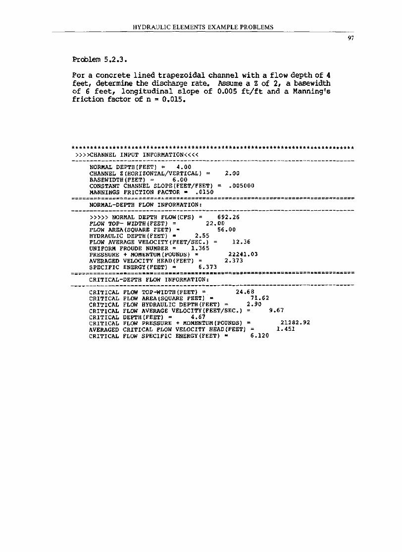
HYDRAULIC ELEMENTS EXAMPLE PROBLEMS
Problem 5.2.3.
For a concrete lined trapezoidal channel with a flow depth of 4 feet, determine the discharge rate. Assume a Z of 2, a basewidth of 6 feet, longitudinal slope of 0.005 ft/ft and a Manning's friction factor of n = 0.015.
97
******.********** ••• *.****************************************** •• ****.****. »»CHANNEL INPUT INFORMATION««
NORMAL DEPT8(FEET) = 4.00 CHANNEL Z(HORIZONTAL/VERTICAL) = 2.00 BASEWIDTH(FEET) = 6.00 CONSTANT CHANNEL SLOPE(FEET/FEET) = .005000 MANNINGS FRICTION FACTOR - .0150
============================================================================ NORMAL-DEPTH FLOW INFORMATION.
»»> NORMAL DEPTH FLOW(CFS) = FLOW TOP- WIDTH(FEET) =
692.26 22.00
FLOW AREA (SQUARE FEET) • HYDRAULIC DEPTH(FEET) = 2.55 FLOW AVERAGE VELOCITY(FEET/SEC.) UNIFORM FROUDE NUMBER = 1.365 PRESSURE + MOMENTUM(POUNDS) -AVERAGED VELOCITY HEAD(FEET) = SPECIFIC ENERGY(FEET) = 6.373
56. 00
12.36
22241.03 2.373
=================================E&E==S===================================== CRITICAL-DEPTH FLOW INFORMATION:
----------------------------------------------------------------------------CRITICAL FLOW TOP-WIDTH(FEET) = 24.68 CRITICAL FLOW AREA (SQUARE FEET) = 71.62 CRITICAL FLOW HYDRAULIC DEPTH(FEET) = 2.90 CRITICAL FLOW AVERAGE VELOCITY(FEET/SEC.) = 9.67 CRITICAL DEPTH(FEET) = 4.67 CRITICAL FLOW PRESSURE + MOMENTUM(POUNDS) = 21282.92 AVERAGED CRITICAL FLOW VELOCITY HEAD(FEET) 1.451 CRITICAL FLOW SPECIFIC ENERGY (FEET) m 6.120
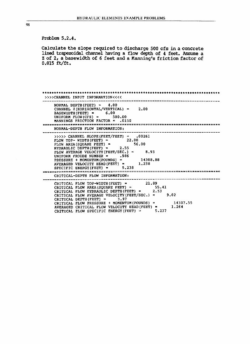
98
HYDRAULIC ELEMENTS EXAMPLE PROBLEMS
Prd:llem 5.2.4.
Calculate the slope required to discharge 500 cfs in a concrete lined trapezoidal channel having a flow depth of 4 feet. Assume a Z of 2, a basewidth of 6 feet and a Manning's friction factor of 0.015 ft/ft.
************************************** •• ****** •••• *** ••• *****.****** •••••••• »»CHANNEL INPUT INFORMATION««
NORMAL DEPTH(FEET) = 4.00 CHANNEL Z(HORIZONTAL/VERTICAL) = 2.00 BASEWIDTH(FEET). 6.00 UNIFORM FLOW(CFS) = 500.00 MANNINGS FRICTION FACTOR = .0150
===D~D=======S==============================================================
NORMAL-DEPTH FLOW INFORMATION:
»»> CHANNEL SLOPE(FEET/FEET) = .00261 FLOW TOP- WIDTH(FEET) = 22.00 FLOW AREA (SQUARE FEET) - 56.00 HYDRAULIC DEPTH(FEET) = 2.55 FLOW AVERAGE VELOCITY(FEET/SEC.) = 8.93 UNIFORM FROUDE NUMBER - .986 PRESSURE + MOMENTUM(POUNDS) = 14308.88 AVERAGED VELOCITY HEAD(FEET) = 1.238 SPECIFIC ENERGY (FEET) = 5.238
=========================================:================================== CRITICAL-DEPTH FLOW INFORMATION:
----------------------------------------------------------------------------CRITICAL FLOW TOP-WIDTH(FEET) = 21.89 CRITICAL FLOW AREA (SQUARE FEET) = 55.41 CRITICAL FLOW HYDRAULIC DEPTH(FEET) = 2.53 CRITICAL FLOW AVERAGE VELOCITY(FEET/SEC.)· 9.02 CRITICAL DEPTH(FEET) = 3.97 CRITICAL FLOW PRESSURE + MOMENTUM(POUNDS) = 14307.55 AVERAGED CRITICAL FLOW VELOCITY HEAD(FEET) = 1.264 CRITICAL FLOW SPECIFIC ENERGY(FEET) = 5.237
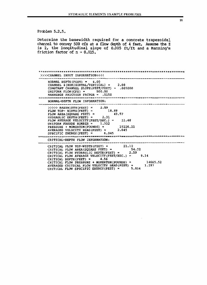
HYDRAULIC ELEMENTS EXAMPLE PROBLEMS
Problem 5.2.5.
Determine the basewidth required for a concrete trapezoidal channel to convey 500 cfs at a flow depth of 4 feet. Assume the Z is 2, the longitudinal slope of 0.005 ft/ft and a Manning's friction factor of n = 0.015.
»»CHANNEL INPUT INFORMATION««
NORMAL DEPTH(FEET) = 4.00 CHANNEL Z(HORIZONTAL/VERTICAL) = 2.00 CONSTANT CHANNEL SLOPE(FEET/FEET) = .005000 UNIFORM FLOW(CFS) = 500.00 MANNINGS FRICTION FACTOR = .0150
99
==================~===============~=========================================
NORMAL-DEPTH FLOW INFORMATION.
»»> BASEWIDTH(FEET) = 2.89 FLOW TOP- WIDTH(FEET) = 18.89
43.57 FLOW AREA(SQUARE FEET) = HYDRAULIC DEPTH(FEET) = 2.31 FLOW AVERAGE VELOCITY(FEET/SEC.) UNIFORM FROUDE NUMBER = 1.332 PRESSURE + MOMENTUM(POUNDS) = AVERAGED VELOCITY HEAD(FEET) = SPECIFIC ENERGY(FEET) = 6.045
11.48
15226.21 2.045
=======================sc=~=================_===============================
CRITICAL-DEPTH FLOW INFORMATION.
CRITICAL FLOW TOP-WIDTH(FEET) = 21.12 CRITICAL FLOW AREA (SQUARE FEET) = 54.72 CRITICAL FLOW HYDRAULIC DEPTB(FEET) = 2.59 CRITICAL FLOW AVERAGE VELOCITY(FEET/SEC.) = 9.14 CRITICAL DEPTH(FEET) = 4.56 CRITICAL FLOW PRESSURE + MOMENTUM(POUNDS) • 14665.52 AVERAGED CRITICAL FLOW VELOCITY BEAD (FEET) 1.297 CRITICAL FLOW SPECIFIC ENERGY(FEET) = 5.854
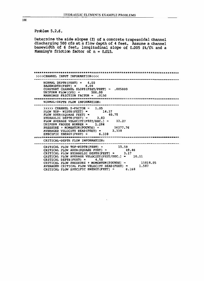
100
HYDRAULIC ELEMENTS EXAMPLE PROBLEMS
Prcblem 5.2.6.
Determine the side slopes (Z) of a concrete trapezoidal channel discharging 500 cfs at a flow depth of 4 feet. Assume a channel basewidth of 6 feet, longitudinal slope of 0.005 ft/ft and a Manning's friction factor of n = 0.015.
****************************** •• *******************************************. »»CBANNEL INPUT INFORMATION««
NORMAL DEPTB(FEET) = 4.00 BASEWIDTH(FEET) = 6.00 CONSTANT CHANNEL SLOPE(FEET/FEET) = .005000 UNIFORM FLOW(CFS) = 500.00 MANNINGS FRICTION FACTOR = .0150
======================~.====================================================
NORMAL-DEPTH FLOW INFORMATION:
1.05 »»> CHANNEL Z-FACTOR = FLOW TOP- WIDTH(FEET) = FLOW AREA(SQUARE FEET) =
14.37 40.75
HYDRAULIC DEPTH(FEET) = 2.83 FLOW AVERAGE VELOCITY(FEET/SEC.) = UNIFORM FROUDE NUMBER = 1.284 PRESSURE + MOMENTUM(POUNDS) = AVERAGED VELOCITY HEAD(FEET) K
SPECIFIC ENERGY(FEET) = 6.338
12.27
16277.76 2.338
======_=======.a.=================================================== •••••• a= CRITICAL-DEPTH FLOW INFORMATION:
CRITICAL FLOW TOP-WIDTH(FEET) = 15.59 CRITICAL FLOW AREA (SQUARE FEET) = 49.46 CRITICAL FLOW HYDRAULIC DEPTH(FEET) a 3.17 CRITICAL FLOW AVERAGE VELOCITY(FEET/SEC.) = 10.11 CRITICAL DEPTH(FEET) = 4.58 CRITICAL FLOW PRESSURE + MOMENTUM(POUNDS) = 15818.05 AVERAGED CRITICAL FLOW VELOCITY HEAD (FEET) = 1.587 CRITICAL FLOW SPECIFIC ENERGY(FEET) = 6.168
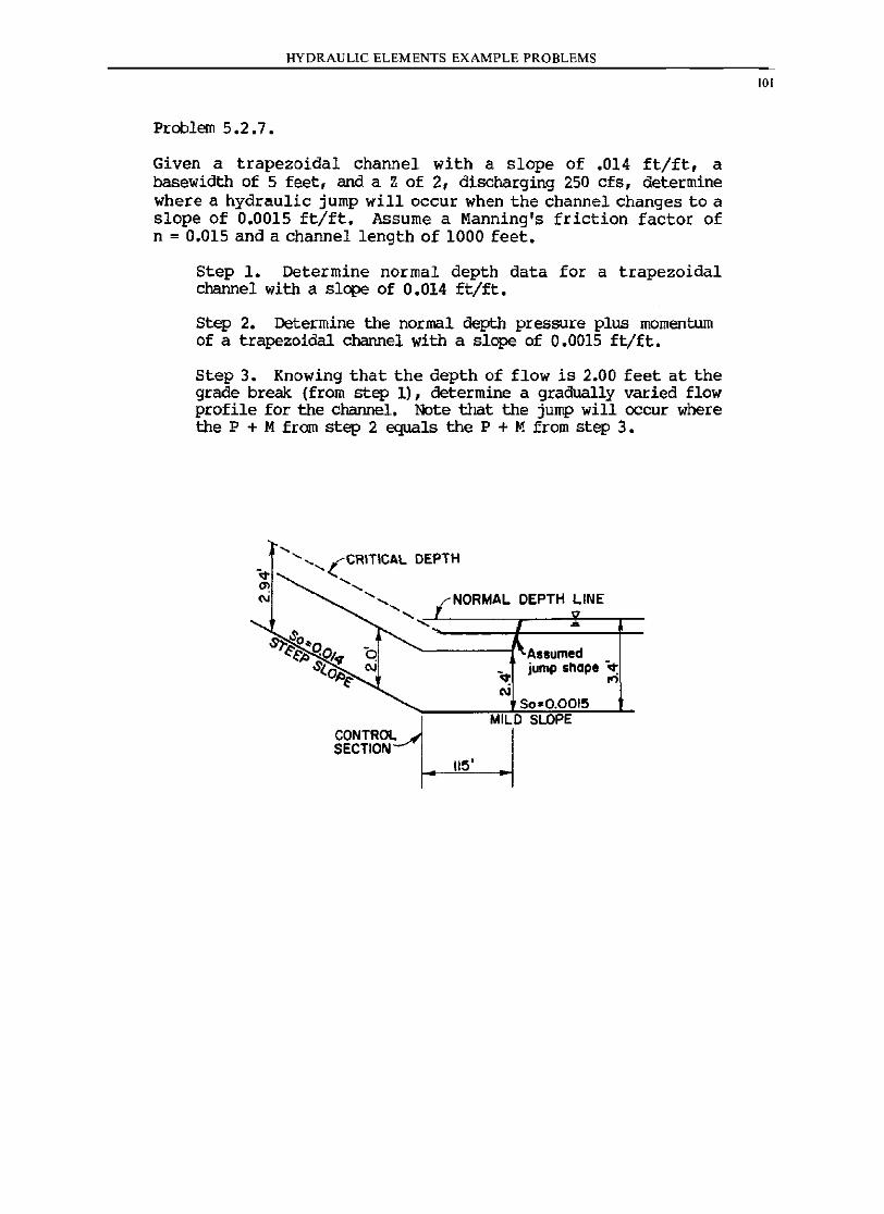
HYDRAULIC ELEMENTS EXAMPLE PROBLEMS
Problem 5.2.7.
Given a trapezoidal channel with a slope of .014 ft/ft, a basewidth of 5 feet, and a Z of 2, discharging 250 cfs, determine where a hydraulic jump will occur when the channel changes to a slope of 0.0015 ft/ft. Assume a Manning's friction factor of n = 0.015 and a channel length of 1000 feet.
Step 1. Determine normal depth data for a trapezoidal channel with a slope of 0.014 ft/ft.
step 2. Determine the normal depth pressure plus momentum of a trapezoidal channel with a slope of 0.0015 ft/ft.
Step 3. Knowing that the depth of flow is 2.00 feet at the grade break (from step 1), determine a gradually varied flow profile for the channel. Note that the jump will occur where the P + M from step 2 equals the P + ~l from step 3 •
.... .... , .... ,(CRITICAL DEPTH
'" ..... NORMAL DEPTH LINE .... ,,,~------,.---, .. --r-
CONTROL SECTION
-........-------if'-Assumed jump shape ":
": 10 C\I
SoaO.0015 MILD SLOPE
115'
101
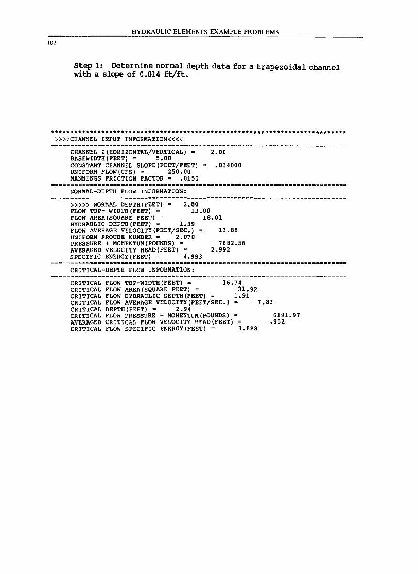
102
HYDRAULIC ELEMENTS EXAMPLE PROBLEMS
Step 1: Determine normal depth data for a trapezoidal channel with a slope of 0.014 ft/ft.
*************************************************************.* •• *.*.** ••• ** »»CHANNEL INPUT INFORMATION««
CHANNEL Z(HORIZONTAL/VERTICAL) = 2.00 BASEWIDTH(FEET) = 5.00 CONSTANT CHANNEL SLOPE(FEET/FEET) = .014000 UNIFORM FLOW(CFS) = 250.00 MANNINGS FRICTION FACTOR = .0150
=================================================-========================== NORMAL-DEPTH FLOW INFORMATION:
2.00 »»> NORMAL DEPTH(FEET) = FLOW TOP- WIDTH (FEET) = FLOW AREA (SQUARE FEET) =
13.00 18.01
HYDRAULIC DEPTB(FEET) = 1.39 FLOW AVERAGE VELOCITY(FEET/SEC.) = UNIFORM FROUDE NUMBER = 2.078 PRESSURE + MOMENTUM(POUNDS) = AVERAGED VELOCITY HEAD(FEET) • SPECIFIC ENERGY(FEET) = 4.993
13. B8
7682.56 2.992
=============== ••• ========================================================== CRITICAL-DEPTH FLOW INFORMATION:
CRITICAL FLOW TOP-WIDTB(FEET) = 16.74 CRITICAL FLOW AREA(SQUARE FEET) = 31.92 CRITICAL FLOW HYDRAULIC DEPTH(FEET) = 1.91 CRITICAL FLOW AVERAGE VELOCITY(FEET/SEC.) = 7.83 CRITICAL DEPTH(FEET) = 2.94 CRITICAL FLOW PRESSURE + MOMENTUM(POUNDS) = 6191.97 AVERAGED CRITICAL FLOW VELOCITY HEAD(FEET) = .952 CRITICAL FLOW SPECIFIC ENERGY(FEET) = 3.B88
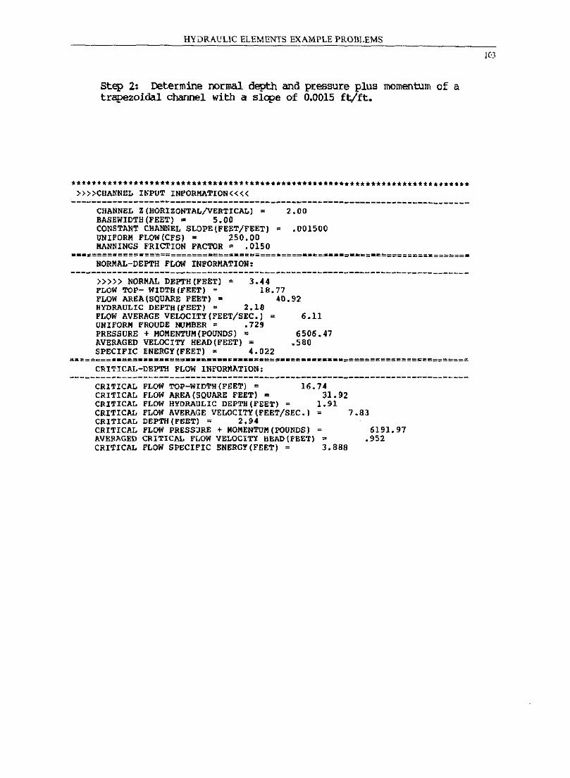
HYDRAULIC ELEMENTS EXAMPLE PROBLEMS
Step 2: Determine normal depth and pressure plus momentum of a trapezoidal channel with a slq;>e of 0.0015 ft/ft.
****.*************************************************.*.******************* »»CHANNEL INPUT INFORMATION««
----------------------------------------------------------------------------CHANNEL Z(HORIZONTAL/VERTICAL) = 2.00 BASEWIDTB(FEET) = 5.00 CONSTANT CHANNEL SLOPE{FEET/FEET) = .001500 UNIFORM FLOW(CFS) • 250.00 MANNINGS FRICTION FACTOR = .0150
===~==================================================-.=.~=================
NORMAL-DEPTH FLOW INFORMATION:
»») NORMAL DEPTH(FEET) = 3.44 FLOW TOP- WIDTH(FEET) = 18.77
40.92 FLOW AREA (SQUARE FEET) • HYDRAULIC DEPTH(FEET) = 2.l8 FLOW AVERAGE VELOCITY(FEET/SEC.) UNIFORM PROUDE NUMBER = .729 PRESSURE + MOMENTUM(POUNDS) = AVERAGED VELOCITY HEAD (FEET) = SPECIFIC ENERGY(FEET) = 4.022
6.11
6506.47 .580
=============================== __ ==_.==$ •••• ======================:========= CRITICAL-DEPTH FLOW INFORMATION:
CRITICAL FLOW TOP-WIDTH(FEET) = 16.74 CRITICAL FLOW AREA (SQUARE FEET) ~ 31.92 CRITICAL FLOW HYDRAULIC DEPTH(FEET) 1.91 CRITICAL FLOW AVERAGE VELOCITY(FEET/SEC.) = 7.83 CRITICAL DEPTH(FEET) = 2.94 CRITICAL FLOW PRESSURE + MOMENTUM(POUNDS) = 6191.97 AVERAGED CRITICAL FLOW VELOCITY HEAD{FEET) ~ .952 CRITICAL FLOW SPECIFIC ENERGY(FEET) = 3.888
103
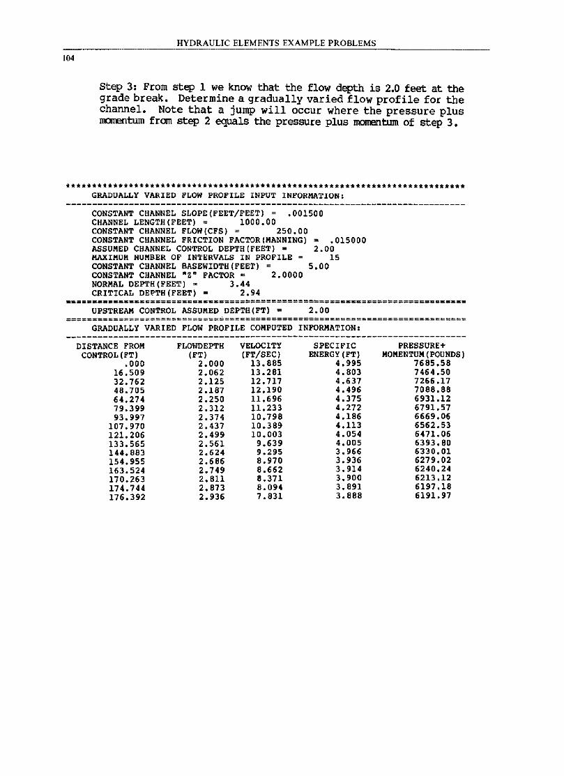
104
HYDRAULIC ELEMENTS EXAMPLE PROBLEMS
Step 3: From step 1 we know that the flow depth is 2.0 feet at the grade break. Determine a gradually varied flow profile for the channel. Note that a jump will occur where the pressure plus IIIOIlElltum from step 2 equals the pressure plus momentum of step 3.
************************************** •••• ************************* ••• *****. GRADUALLY VARIED FLOW PROFILE INPUT INFORMA1'ION,
CONSTANT CHANNEL SLOPE(FEET/FEET) = .001500 CHANNEL LENGTH(FEET) = 1000.00 CONSTANT CHANNEL FLOW(CFS) = 250.00 CONSTANT CHANNEL FRICTION FACTOR(MANNING) a .015000 ASSUMED CHANNEL CONTROL DEPTH (FEET) • 2.00 MAXIMUM NUMBER OF INTERVALS IN PROFILE = 15 CONSTANT CHANNEL BASEWIDTH(FEET) 5.00 CONSTANT CHANNEL ·Z· FACTOR D 2.0000 NORMAL DEPTH(FEET) = 3.44 CRITICAL DEPTH(FEET) = 2.94
UPSTREAM CONTROL ASSUMED DEPTH(FT) = 2.00 ============================================================================
GRADUALLY VARIED FLOW PROFILE COMPUTED INFORMATION,
DISTANCE FROM FLO~IDEPTH VELOCITY SPECIFIC PRESSURE+ CONTROL (FT) (FT) (FT/SEC) ENERGY (FT) MOMENTUM (POUNDSj
,000 2.000 13.885 4.995 7685.58 16,509 2.062 13.281 4.S03 7464.50 32.762 2.125 12.717 4.637 7266.17 4S.705 2.1S7 12.190 4.496 7088.88 64.274 2.250 11.696 4.375 6931.12 79.399 2.312 11.233 4.272 6791. 57 93.997 2.374 10.798 4.186 6669,06
107.970 2.437 10.389 4.113 6562,53 121.206 2.499 10.003 4.054 6471. 06 133.565 2.561 9.639 4.005 6393.80 144.883 2.624 9.295 3.966 6330,01 154.955 2.686 8.970 3.936 6279,02 163.524 2.749 8.662 3.914 6240.24 170.263 2. Sl1 8.371 3.900 6213.12 174.744 2.873 8.094 3.891 6197,18 176.392 2.936 7.831 3.888 6191. 97
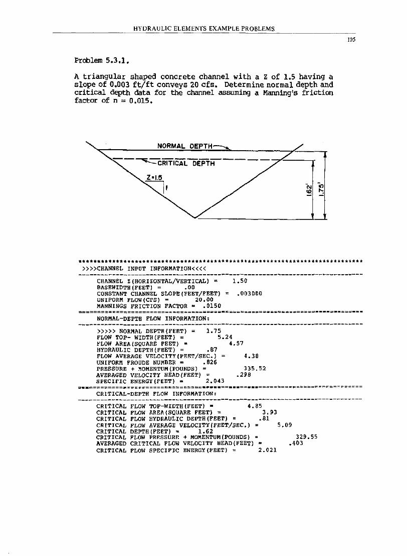
HYDRAULIC ELEMENTS EXAMPLE PROBLEMS
Problem 5.3.1.
A triangular shaped concrete channel with a z of 1.5 having a slope of 0.003 ft/ft conveys 20 cfs. Determine normal depth and critical depth data for the channel assuming a Manning's friction factor of n = 0.015.
NORMAL DEPTH
105
••• ***.**************.********************************A •• * ••• ******* •• *.* •• * »»CHANNEL INPUT INFORMATION««
CHANNEL Z(HORIZONTAL/VERTICAL) = 1.50 BASEWIDTH(FEET) = .00 CONSTANT CHANNEL SLOPE(FEET/FEET) = .003000 UNIFORM FLOW(CFS) = 20.00 MANNINGS FRICTION FACTOR = .0150
NORMAL-DEPTH FLOW INFORMATION: ----------------------------------------------------------------------------
»»> NORMAL DEPTH(FEET) 1. 75 FLOW TOP- WIDTH(FEET) = FLOW AREA(SQUARE FEET) = HYDRAULIC DEPTH(FEET) = .87 FLOW AVERAGE VELOCITY(FEET/SEC.) UNIFORM FROUDE NUMBER = .826 PRESSURE + MOHENTUH(POUNDS) = AVERAGED VELOCITY HEAD(FEET) =
5.24 4.57
SPECIFIC ENERGY(FEET) = 2.043
4.38
335.52 .298
===~======================~=======.============~============================
CRITICAL-DEPTH FLOW INFORMATION: ----------------------------------------------------------------------------
CRITICAL FLOW TOP-WIDTH(FEET) = 4.85 CRITICAL FLOW AREA (SQUARE FEET) = 3.93 CRITICAL FLOW HYDRAULIC DEPTH(FEET) = .81 CRITICAL FLOW AVERAGE VELOCITY(FEET/SEC.) = 5.09 CRITICAL DEPTH(FEET) = 1.62 CRITICAL FLOW PRESSURE + MOMENTUM(POUNDS) = 329.55 AVERAGED CRITICAL FLOW VELOCITY HEAD(FEET) = .403 CRITICAL FLOW SPECIFIC ENERGY(FEET) = 2.021
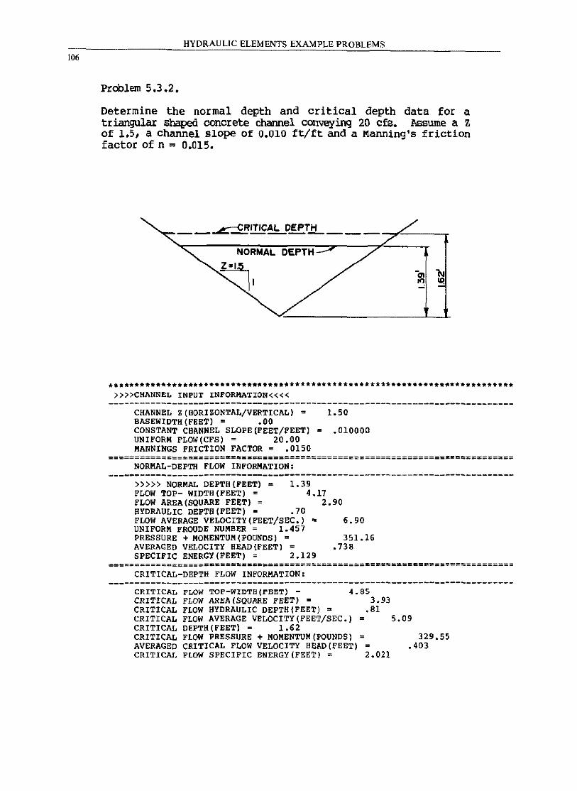
106
HYDRAULIC ELEMENTS EXAMPLE PROBLEMS
Problem 5.3.2.
Determine the normal depth and critical depth data for a triangular shaped concrete channel conveying 20 cfs. Assume a Z of 1.5, a channel slope of 0.010 ft/ft and a Manning's friction factor of n = 0.015.
__ ..L::CRITICAL OEPTlL ___ -,rr ___ --.-
NORMAL DEPTH
~,
**************************************************************************** »»CHANNEL INPUT INFORMATION««
CHANNEL Z(HORIZONTAL/VERTICAL) = 1.50 BASEWIDTH(FEET) = .00 CONSTANT CHANNEL SLOPE(FEET/FEET) = .010000 UNIFORM FLOW(CFS) = 20.00 MANNINGS FRICTION FACTOR = .0150
=====================~-= ••• =====================:============== •• ========~== NORMAL-DEPTH FLOW INFORMATION:
1.39 »»> NORMAL DEPTH(FEET) = FLOW TOP- WIDTH(FEET) = FLOW AREA (SQUARE FEET) =
4.17 2.90
HYDRAULIC DEPTH(FEET) = .70 FLOW AVERAGE VELOCITY(FEET/SEC.) ~ UNIFORM FROUDE NUMB~R = 1.457 PRESSURE + MOMENTUM(POUNDS) = AVERAGED VELOCITY BEAD(FEET) = SPECIFIC ENERGY(FEET) = 2.129
6.90
351.16 .738
===================.======.===========~=====================================
CRITICAL-DEPTH FLOW INFORMATION:
CRITICAL FLOW TOP-WIDTH(PEET) = 4.85 CRITICAL FLOW AREA (SQUARE FEET) = 3.93 CRITICAL FLOW HYDRAULIC DEPTH(FEET) = .81 CRITICAL FLOW AVERAGE VELOCITY(FEE~/SEC.) = 5.09 CRITICAL DEPTH (FEET) = 1.62 CRITICAL FLOW PRESSURE + MOMENTUM (POUNDS) = 329.55 AVERAGED CRITICAL FLOW VELOCITY HE~D(FEET) .403 CRITICAL FLOW SPECIFIC ENERGY(FEET) = 2.021
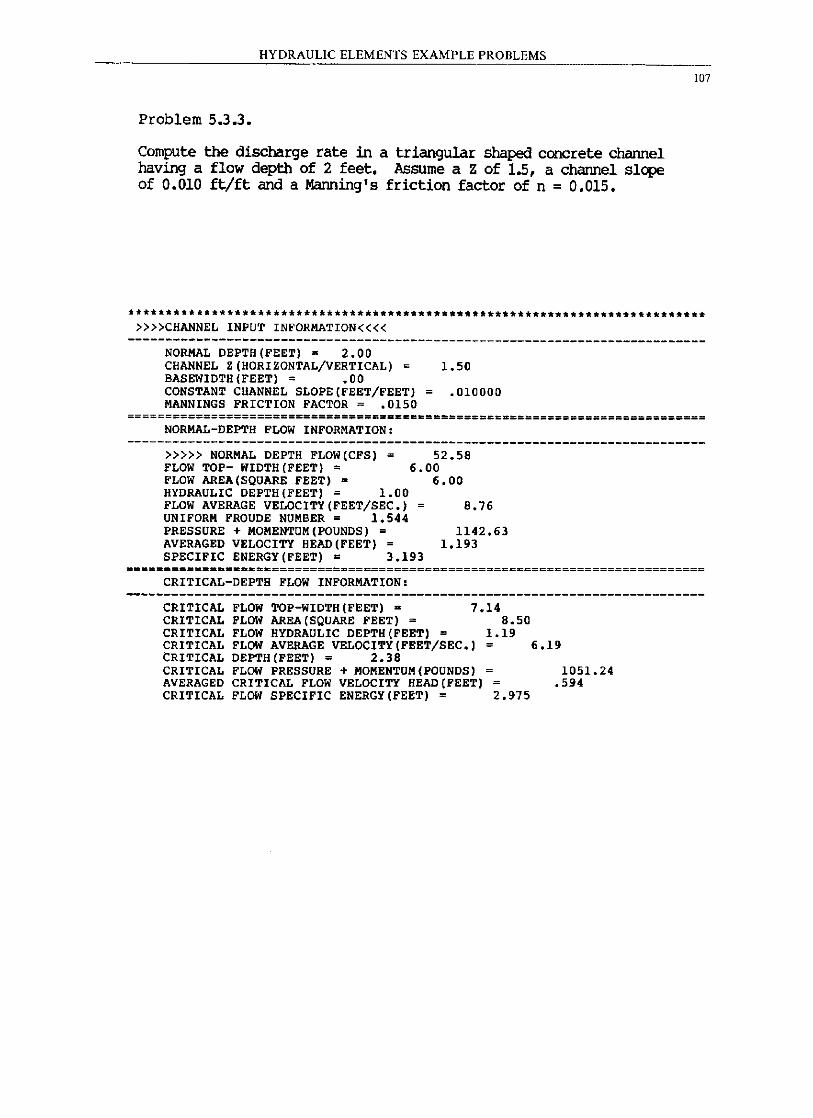
HYDRAULIC ELEMENTS EXAMPLE PROB=-::L=-::EccM:=:S=---________ _
Problem 5.3.3.
Compute the discharge rate in a triangular shaped concrete channel having a flow depth of 2 feet. Assume a Z of 1.5, a channel slope of 0.010 ft/ft and a Manning's friction factor of n = 0.015.
107
*******.*******************************************.*.**** •• ***** •••• * •••• ** »»CHANNEL INPUT INFORMATION««
----------------------------------------------------------------------------NORMAL DEPTH(FEET)· 2.00 CHANNEL Z(HORIZONTAL/VERTICAL) = 1.50 BASEWIDTH(FEET) = .00 CONSTANT CHANNEL SLOPE(FEET/FEET) = .010000 MANNINGS FRICTION FACTOR = .0150
=================================_==c======================================= NORMAL-DEPTH FLOW INFORMATION:
»»> NORMAL DEPTH FLOW(CFS) = FLOW TOP- WIDTH (FEET) = FLOW AREA (SQUARE FEET) a
HYDRAULIC DEPTH(FEET) = 1.00 FLOW AVERAGE VELOCITY(FEET/SEC.) UNIFORM FROUDE NUMBER = 1.544 PRESSURE + MOMENTUM(POUNDS) = AVERAGED VELOCITY HEAD (FEET) =
52.58 6.00
6.00
8.76
1142.63 1.193
SPECIFIC ENERGY(FEET) = 3.193 ============================================================================
CRITICAL-DEPTH FLOW INFORMATION:
CRITICAL FLOW TOP-WIDTH(FEET) • 7.14 CRITICAL FLOW AREA(SQUARE FEET) = 8.50 CRITICAL FLOW HYDRAULIC DEPTH(FEET) = 1.19 CRITICAL FLOW AVERAGE VELOCITY(FEET/SEC.) = 6.19 CRITICAL DEPTH(FEET) = 2.38 CRITICAL FLOW PRESSURE + MOMENTUM(POUNDS) = 1051.24 AVERAGED CRITICAL FLOW VELOCITY HEAD (FEET) .594 CRITICAL FLOW SPECIFIC ENERGY(FEET) = 2.975
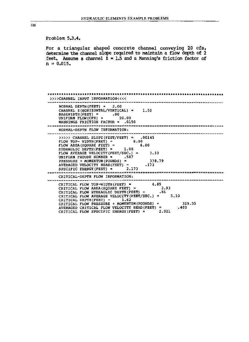
108
HYDRAULIC ELEMENTS EXAMPLE PROBLEMS
Problem 5.3.4.
For a triangular shaped concrete channel conveying 20 cfs, determine the channel slq:>e required to maintain a flow depth of 2 feet. Assume a channel Z = 1.5 and a Manning'S friction factor of n ,. 0.015.
************************************************************ ••• ***.********* »»CHANNEL INPUT INFORMATION««
NORMAL DEPTH(FEET) = 2.00 CHANNEL Z(HORIZONTAL/VERTICAL) = 1.50 BASEWIDTH(FEET) = .00 UNIFORM FLOW(CFS) = 20.00 MANNINGS FRICTION FACTOR ~ .0150
==~===============================~=========================================
NORMAL-DEPTH FLOW INFORMATION.
»»> CHANNEL SLOPE(FEET/FEET) = .00145 FLOI'l TOP- WIDTH (FEET) = 6.00 FLOW AREA (SQUARE FEET) = 6.00 HYDRAULIC DEPTH(FEET)· 1.00 FLOW AVERAGE VELOCITY(FEET/SEC.) 3.33 UNIFORM FROUDE NUMBER = .587 PRESSURE + MOMENTUM (POUNDS) = 378.79 AVERAGED VELOCITY HEAD(FEET) = .173 SPECIFIC ENERGY(FEET) • 2.173
===============================================~.==============-============
CRITICAL-DEPTH FLOW INFORMATION.
CRITICAL FLOW TOP-WIDTH(FEET) = 4.85 CRITICAL FLOW AREA (SQUARE FEET) = 3.93 CRITICAL FLOW HYDRAULIC DEPTH(FEET) = .81 CRITICAL FLOW AVERAGE VELOCITY(FEET/SEC.) = 5.10 CRITICAL DEPTH(FEET) = 1.62 CRITICAL FLOW PRESSURE + MOMENTUM(POUNDS) = 329.55 AVERAGED CRITICAL FLOW VELOCITY HEAD (FEET) = .403 CRITICAL FLOW SPECIFIC ENERGY(FEET) = 2.021
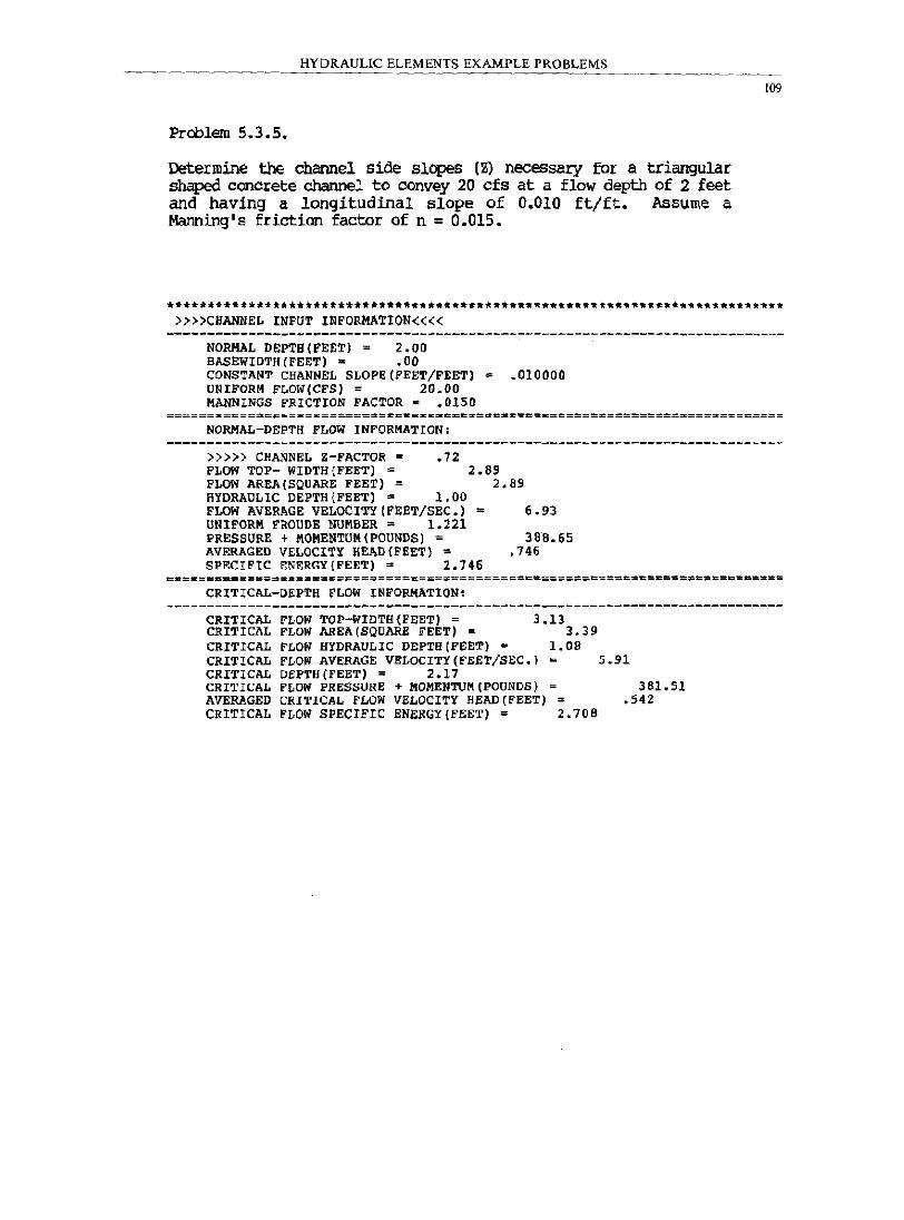
HYDRAULIC ELEMENTS EXAMPLE PROBLEMS
Problem 5.3.5.
Determine the channel side slopes (Z) necessary for a triangular shaped concrete channel to convey 20 efs at a flow aeptb of 2 feet and having a longitudinal slope of 0.010 ft/ft. Assume a Manning's friction factor of n = 0.015.
»»CHANNEL INFur INFORMATION««
NORMAL DEPTB(FEET) = 2.00 BASEWIDTH(FEET) ~ .00 CONSTANT CHANNEL SLOPE(FEET/FEET) = .010000 UNIFORM FLOW(CFS) = 20.00 MANNINGS FRICTION FACTOR. .0150
NORMAL-DEPTH FLOW INFORMATION,
»»} CHANNEL Z-FACTOR = .72 FLOW TOP- WIDTH (FEET) = 2.69 FLOW AR~(SQUARE FEET) = 2.89 HYDRAULIC DEPTH(FEET) = 1.00 FLOW AVERAGE VELOCITY (FEET/SEC.) = 6.93 UNIFORM FROUDE NUMBER = 1.221 PRESSURE + MOMENTUM (POUNDS) = 388.65 AVERAGED VELOCITY HEAD(FEET) = .746 SPECIFIC ENF.RGY{FEET) = 2.146
109
===_====_====$================================================_========c==== CRITICAL-DEPTH FLOW I~FORMATION:
CRITICAL FLOW TOP-WIDTH{FEET) = 3.13 CRITICAL FLOW AREA (SQUARE FEET) = 3.39 CRITICAL FLOW HYDRAULIC DEPTH{FEET) ~ 1.0B CRITICAL FLOW AVERAGE VELOCITY(FEET/SEC.) ~ 5.91 CRITICAL DEPTH{FEET) = 2.11 CRITICAL FLOW PRESSURE + MOMENTUM(POUNDS) = 381.51 AVERAGED CRITICAL FLOW VELOCITY HEAD (FEET) = .542 CRITICAL FLOW SPECIFIC ENERGY{FEET) = 2.70B
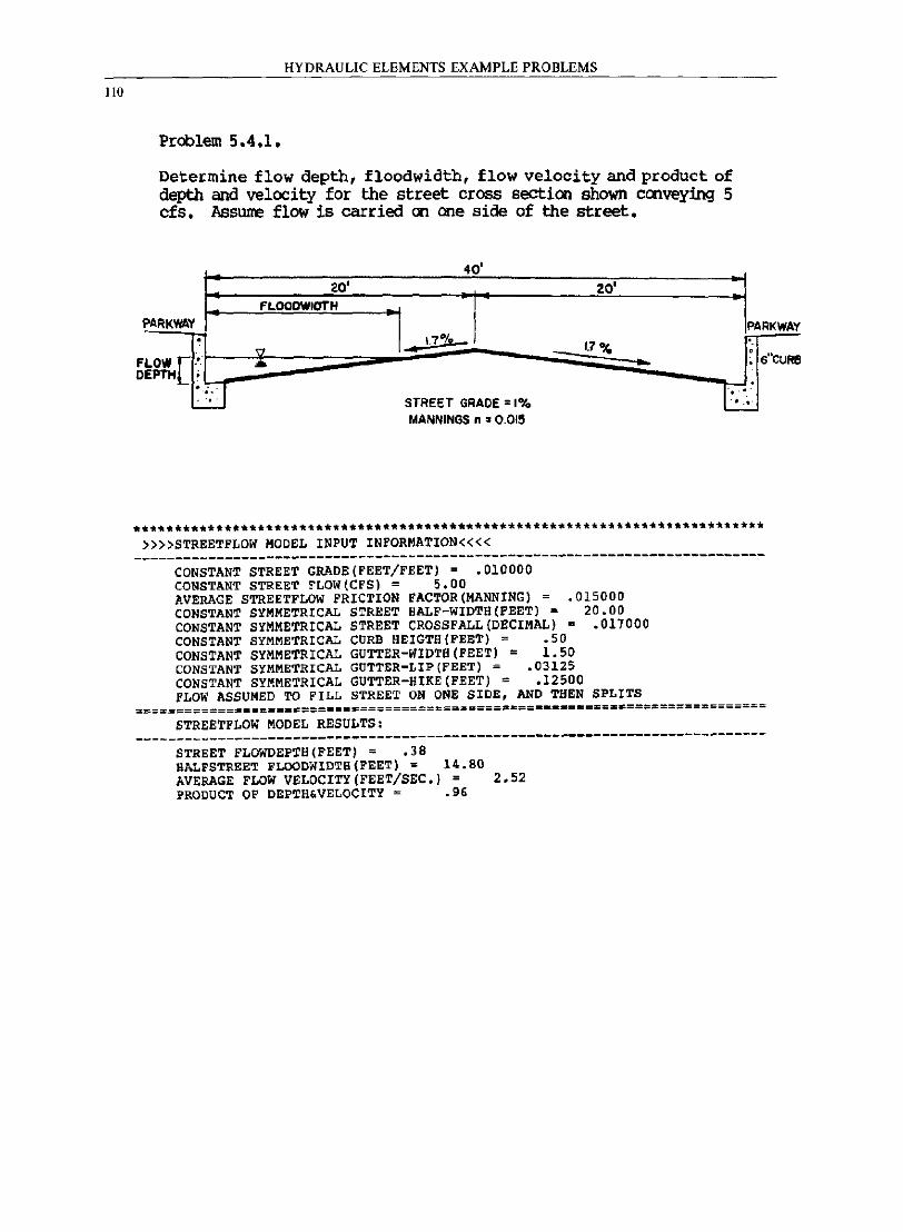
110
HYDRAULIC ELEMENTS EXAMPLE PROBLEMS
Problem 5.4.1.
Determine flow depth, floodwidth, flow velocity and product of depth and velocity for the street cross section shown cmveying 5 cfs. lIssurne flow is carried an me side of the street.
1=
40' 20'
17% ~ I' 20'
:1 PARKWAY:
fLOOOWIOTH
~I '<7 1.7 "4 .. .. ;;;; ...
DEPTH ;
PARKWAY '. ~ 6
ueUR! FLOW [.'.
l:lJ TI ' . , ... STREET GRADE = 1% .... MANNINGS n = 0.0115
.*~~*.*******.* •• *** •••• ***.** •••••• *.** ••• ** •••••• * •• •••••••••••••••••••••• »»STREETFLOW MODEL INPUT INFORMATION««
----------------------------------------------------------------------------CONSTANT STREET GRADE(FEET/FEET) = ,010000 CONSTANT STREET FLOW(CFS) = 5.00
.015000 20.00
.017000
AVERAGE STREETFLOW FRICTION FACTOR(MANNING) = CONSTANT SYMMETRICAL STREET HALF-WIDTH(FEET) -CONSTANT SYMMETRICAL STREET CROSSFALL(DECIMAL) • CONSTANT SYMMETRICAL CURB HEIGTH(FEET) = .50 CONSTANT SYMMETRICAL GUTTER-WIDTH(FEET) = 1.50 CONSTANT SYMMETRICAL GUTTER-LIP(FEET) = .03125 CONSTANT SYMMETRICAL GUTTER-HIKE(FEET) = .12500 FLOW ASSUMED TO FILL STREET ON ONE SIDE, AND THEN SPLITS
=~================s=========================.c==._ •• _.=~=.s======~========== STREETFLOW MODEL RESULTS:
----------------------------------------------------------------------------STREET FLOWDEPTH(FEET) = .38 RALFSTREET FLOODWIDTB(FEET) = 14.80 AVERAGE FLOW VELOCITY (FEET/SEC.) = 2.52 PRODUCT OF DEPTH&VELOCITY = .96
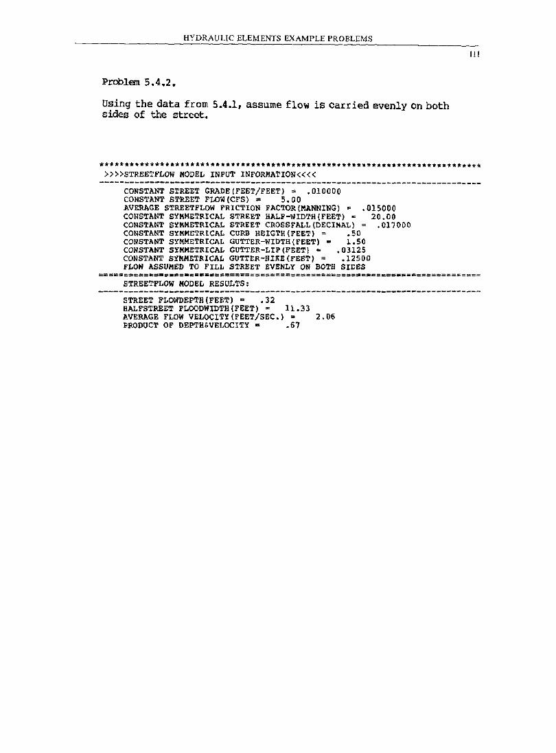
HYDRAULIC ELEMENTS EXAMPLE PROBLEMS
Problem 5.4.2.
Using the data from 5.4.1, assume flow is carried evenly on both sides of the street.
»»STREETFLOW MODEL INPUT INFORMATION««
III
---------------------------------------------------------------.------------CONSTANT STREET GRADE(FEET/FEET); .010000 CONSTANT STREET FLDW(CFS) $ 5.00 AVERAGE STREETFLOW FRICTION FACTOR[MANNING) ; CONSTANT SYMMETRICAL STREET HALF-WIDTH[FEET) ~ CONSTANT S~MMETRICAL STREET CROSSFALL[DECIMAL) CONSTANT S~MMETRICAL CURB HEIGrH[FEET); .50
.015000 20.00
.017000
CONSTANT S~MMETRICAL GUTTER-WIDTH[FEET) = 1.50 CONSTANT S~MMETRICAL GUTTER-LIP[FEET) = .03125 CONSTANT SYMMETRICAL GUTTER-HIKE(PEET) = .12500 FLOW ASSUMED TO FILL STREET EVENLY ON BOTH SIDES
STREETFLOW MODEL RESOLTS:
STREET FLOWDEPTB(FEET) = .32 HALFSTREET FLOODWIDTH(FEET) = 11.33 AVERAGE FLOW VELOCITY(FEET/SEC.) = 2.06 PRODUCT OF DEPTH&VELOCITY = .67
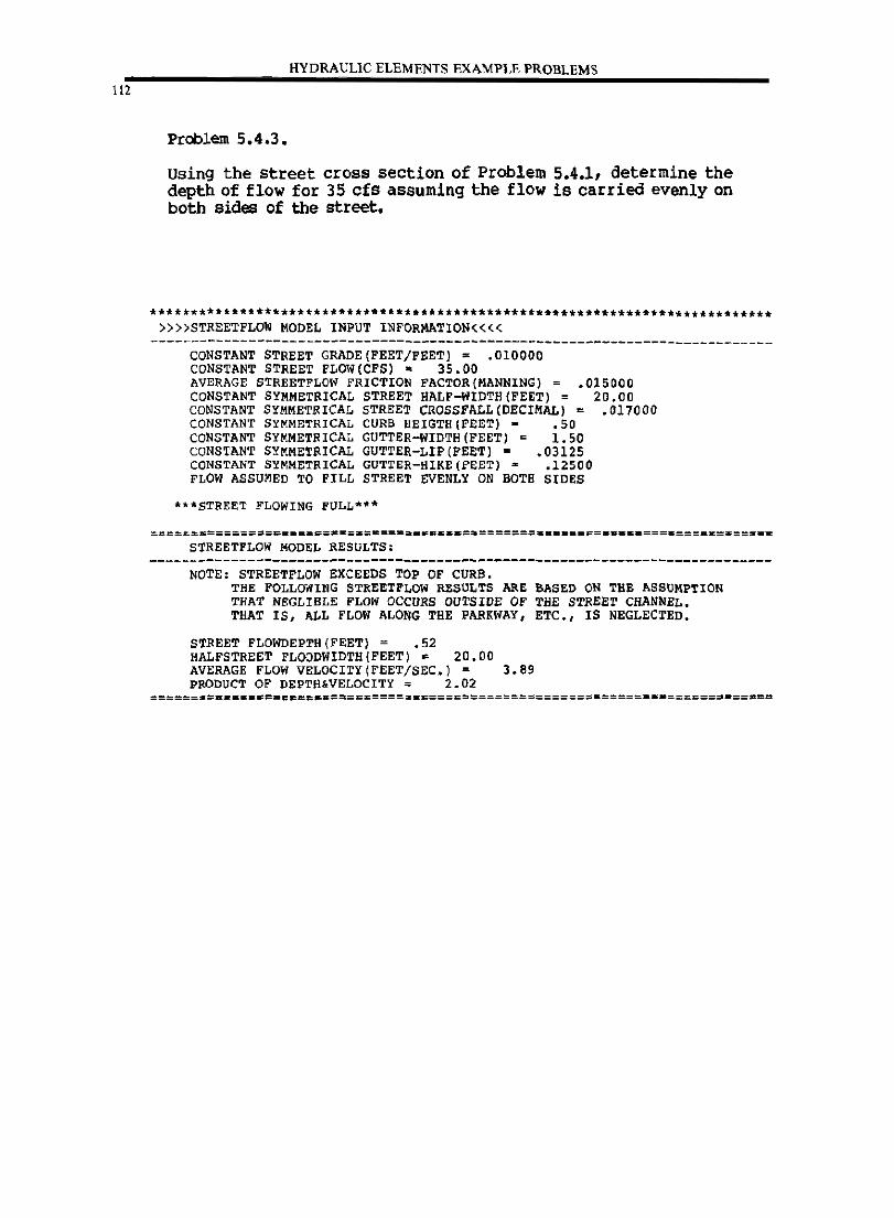
112
___ HYDRAULIC ELEMENTS EXAMPLE PROBLEMS
Problem 5.4.3.
Using the street cross section of Problem 5.4.1, determine the depth of flow for 35 cfs assuming the flow is carried evenly on both sides of the street •
• ********************.*********.*.*************.*.*************.************ »»STREETFLOW MODEL INPUT INFORMATION««
----------------------------------------------------------------------------CONSTANT STREET GRADE (FEET/FEET] = .010000 CONSTANT STREET FLOW(CFS]. 35.00
.015000 20.00
.017000
AVERAGE STREETFLOW FRICTION FACTOR(MANNING] CONSTANT SYMMETRICAL STREET HALF-WIDTH(FEET] = CONSTANT SYMMETRICAL STREET CROSSFALL(DECIMAL) = CONSTANT SYMMETRICAL CURB HEIGTH(FEET] - .50 CONSTANT SYMMETRICAL GUTTER-WIDTH(FEET] = 1.50 CONSTANT SYMMETRICAL GUTTER-LIP(FEET] - .03125 CONSTANT SYMMETRICAL GUTTER-HIKE(FEET) = .12500 FLOW ASSUMED TO FILL STREET EVENLY ON BOTH SIDES
***STREET FLOWING FULL*~*
~========================a=======_ •••• =.==================================== STREETFLOW MODEL RESULTS;
NOTE; STREETFLOW EXCEEDS TOP OF CURB. THE FOLLOWING STREET FLOW RESULTS ARE BASED ON THE ASSUMPTION THAT NEGLIBLE PLOW OCCURS OUTSIDE OP THE STREET CHANNEL. THAT IS, ALL PLOW ALONG THE PARKWAY, ETC., IS NEGLECTED.
STREET FLOWDEPTH(FEET] = .52 HALFSTREET FLOODWIDTH(FEET) = 20.00 AVERAGE FLOW VELOCITY(FEET/SEC.) = 3.89 PRODUCT OF DEPTH.VELOCITY = 2.02
:=====:======~==c~==.=====~===========================================-==_==
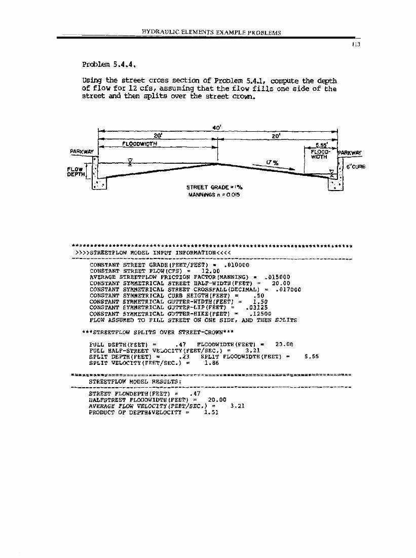
________ -=H-'-Y=-D=-=-R:c;AVLlC ELEMENTS EXAMPLE PROBLEMS
Prcblem 5.4.4.
Using the street cross section of Problem 5.4.1, compute the depth of flow for 12. cfs, assuming that the flow fills one side of the street and then splits over the street crown.
40' 20' zo'
FLOODWIOTfi 5,55'
113
PARKWAY FLOOD- PARK .... p,y
F o
• \1 WIDTH
LOW[: - l7% sUcu .... ,,' EPTH '.
D G ~, ,- STREET GRADE = I "I. . .
MANNtNGS n = 0.015
********.********~.**.*****~.*.**********.******.~*.~. ******** •• *._***.***** »»STREETFLOW MODEL INPUT INFORMATION««
----------------------------------------------------------------------------CONSTANT STREET GRADE(FEET/FEET). .010000 CONSTANT STREET FLOW(CFS) = 12.00
.015000 20.00
.017000
AVERAGE STREETFLOW FRICTION FACTORIMANNING) • CONSTANT SYMMETRICAL STREET 8ALF-WIDTH(FEET) = CONSTANT SYMMETRICAL STREET CROSSFALL(DECIMAL) = CONSTANT SYMMETRICAL CURB BEIGTH{FEET) = .50 CONSTANT SYMMETRICAL GUTTER-WIDTH(FEETJ = 1.50 CONSTANT SYMMETRICAL GUTTER-LIP(FEET) = .03125 CONSTANT SYMMETRICAL GOTTER-HIKE{FEET) - _12500 FLOW ASSUMED TO FILL STREET ON ONE SIDE, AND THEN
"'STREETFLDW SPLITS OVER STREET-CROWN'"
SPLITS
FULL DEPTH(rEET) - .47 FLOODWIDTH(FEET). 20.00 FULL HALF-STREET VELOCITY(FEET/SEC.) = 3.21 SPLIT OEPTH(FEET) ~ .23 SFLIT FLOODWIDTH(FEET) - 5.55 SPLIT VELOCITY(FEET/SEC.) = 1.86
STREETFLOW MODEL RESULTS: ----------------------------------------------------------------------------
STREET FLOWDEPTBIFEET) = .47 HALFSTREET FLOODWIDTH(FEET) = 20.00 AVERAGE FLOW VELOCITy/FEET/SEC.) = 3_21 PRODUCT OF DEPTH,VELOCITY = 1.51
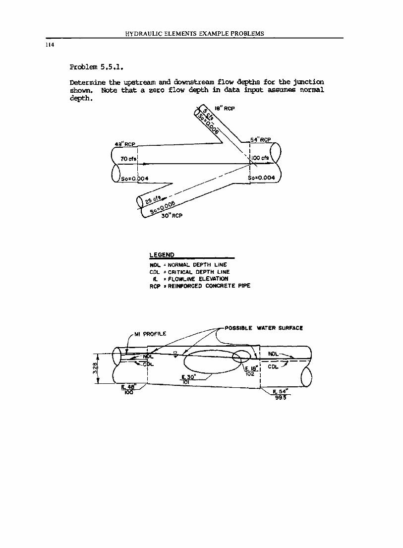
114
HYDRAULIC ELEMENTS EXAMPLE PROBLEMS
Problem 5.5.1.
Dete!:mine the upstJ:eam and downstJ:eam flow depths fo!: the jWlCtion shown. Note that a ze!:o flow depth in data input assumes normal depth.
LEGEND
54"RCP I I
71' IOOcfs _~ br
I I
~ So=0.004
NOL • NORMAL DEPTH LINE COL • CRITICAL DEPTH LINE Il • FLOWl.INE El.EVATION
RCP • REINfORCEO CONCRETE PIPE
loll PROfiLE ~--:;rPOSSI8LE WATER SURFACE
JE.3Q" / tOl
NIlL
--7--\ua:: COL IOZ I
I
'" 1l54" 99.5
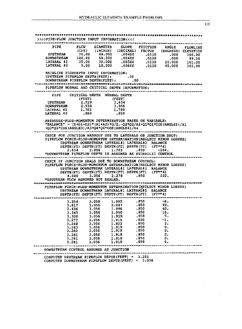
HYDRAULIC ELEMENTS EXAMPLE PROBLEMS
* •• *.** •• ***.*** •• ** ••• ***_* •• *_* __ ._ ••••• *** •• **.**.*t*t* __ *_ .. t ••••• *._*** »»PIPE-FLOW JUNCTION INPUT INFORMATION««
----------------------------------------------------------------------------PIPE
UPSTRElIlI DOWNSTREAM LATERAL tl LATERAL .2
FLOW (CFS) 70.00
100.00 25.00
5.00
DIAMETER (INCHES)
48.000 54.000 30.000 18.000
SLOPE (DECIMAL)
.00400
.00400
.00500
.00600
MAINLINE FLO"~EPTH INPUT INFORMATION: UPSTREAM PIPEFLOW DEPTH(FEET). .00 DOWNSTREAM PIPEFLOW DEPTB(FEET): .00
FRICTION FACTOR
.0130
.0130
.0130
.0130
PIPEFLOW NORMAL AND CRITICAL DEPTH INFORMATION.
ANGLE (DEGREES)
.000
.000 20.000 45.000
FLOWLINB ELEVATION
100.00 99.50
101.00 102.00
----------------------------------------------------------------------------PIPE
UPSTREAII DOWNSTREAM LATERAL tl LATERAL .2
CRI'J:ICAL DEPTi! (FEET) 2.529 2.938 1.703
.860
NORMAL DEP'ri! (FEET) 2.634 3.056 1. 790
.850
PRESSURE-PLUS-MOMENTUM DETERMINATION BASED ON VARIABLE. "BALANCE" = (Z+DI-D2)*(Al+A2)*G/2.-Q2*Q2/A2+Ql*Ql*COS(ANGLEl)/Al +Q3*Q3"COS(ANGLE3)/A3+Q4*Q4*COS(ANGLE4)/A4
CHECI FOR JUNCTION WASHOUT DUE TO LATERALS OR JUNCTION DROP, PIPEFLOW FORCE-PLUS-MOMENTUM DETERMINATION(NEGLECT MINOR LOSSES)
UPSTREAM DOWNSTREAM LATERAL.1 LATERAL.2 BALANCE DEPTH(FT) DEPTH (FT) DEPTH (FT) DEPTH (FT) (FT**4)
2.634 3.056 1.703 .850 -104. "DOWNSTREAM PIPE FLOW DEPTH IS ASSUMED AS HYDRAULIC CONTROL
CHECK IF JUNCTION SEALS DUE TO DOWNSTREAM CONTROL, PIPEFLOW FORCE-PLUS-MOMENTUM DETERMINATION(NEGLECT MINOR LOSSES)
UPSTREAM DOWNSTREAM LATERAL.l LATERAL'2 BALANCE DEPTH(FT) DEPTH (FT) DEPTH (FT) DEPTH (FT) (FT**4)
4.000 3.056 2.278 .850 222 • • UPSTREAM FLCW ASSUMED NOT SEALED.
PIPEFLOW FORCE-PLUS-MOMENTUM DETERMINATION(~EGLECT MINOR LOSSES) UPSTREAII DOWNSTREAM LATERALIl LATERAL.2 BALANCE DEPTH (FT) DEPTH (FT) DEPTH (FT) DEPTH(FT} (FT**4)
---------.------------------------------------------------------------------3.254 3.056 1.905 .850 -6. 3.617 3.056 2.087 .850 92. 3.436 3.056 1.996 .850 40. 3.345 3.056 1.950 .850 16. 3.300 3.056 1.928 .850 5. 3.277 3.056 1.916 .650 -1. 3.288 3.056 1.922 .850 2. 3.283 3.056 1.919 .850 o. 3.280 3.056 1.918 .850 O. 3.281 3.056 1.919 .850 o. 3.281 3.056 1.918 .850 o. 3.281 3.056 lo9l6 • 850 o •
------------------------------------------------------.---------------------DOWNSTREAM CONTROL ASSUMED AT JUNCTION
----------------------------------------------------------------------------COMPUTED UPSTREAM PIPEFLOW DEPTH(FEET) = 3.281 COMPUTED DOWNSTREAM PIPEFLOW DEPTH(FEET) = 3.056
115
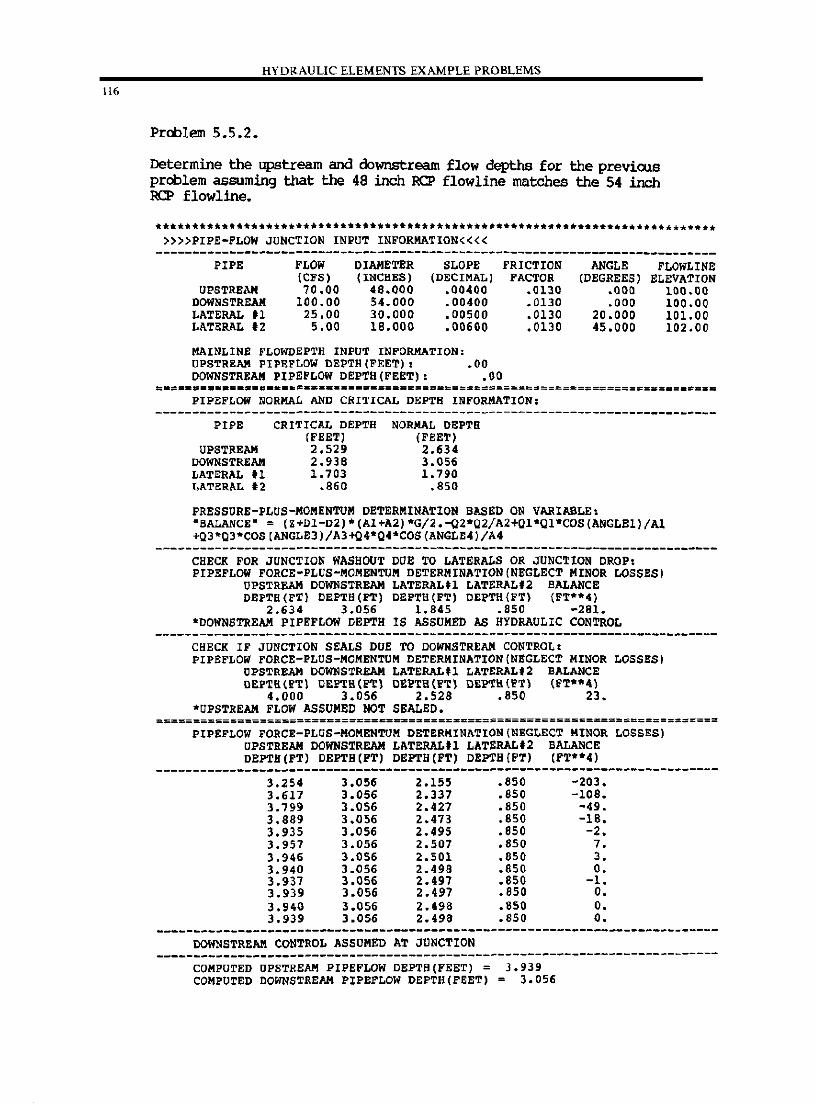
116
HYDRAULIC ELEMENTS EXAMPLE PROBLEMS
Problem 5.5.2.
Determine the upstream and downstream flow depths for the previous problem assuming that the 48 inch RCP flowline matches the 54 inch RCP flowline.
»»PIPE-FLOW JUNCTION INPUT INFORMATION«« ----------------------------------------------------------------------------
PIPE
UPSTREAM DOWNSTREAM LATERAL tl LATERAL 12
FLOW (CFS) 70.00
100.00 25.00
5.00
DIAMETER (INCHES)
48.000 54.000 30.000 18.000
SLOPE (DECIMAL)
.00400
.00400
.00500
.00600
MAINLINE FLOWDEPTH INPUT INFORMATION: UPSTREAM PIPEFLOW DEPTH (FEET) , .00 DOWNSTREAM PIPEFLOW DEPTH(FEET): .00
FRICTION FACTOR
.0130
.0130
.0130
.0130
ANGLE (DEGREES)
.000
.000 20.000 45.000
FLOWLINE ELEVATION
100.00 100.00 101. 00 102.00
=.= •• = •••• =-= •• -••• ~.~.= .•..•. ===============~=======================.=.==~= PIPEFLOW NORMAL AND CRITICAL DEPTH INFORMATION,
PIPE
UPSTREAM DOWNSTREAM LATERAL tl LATERAL 12
CRITICAL DEPTH (FEET) 2.529 2.938 1.703
.860
NORMAL DEPT!! (FEET) 2.634 3.056 1. 790
.850
PRESSURE-PLUS-MOMENTUM DETERMINATION BASED ON VARIABLE, "BALANCE" = (Z+DI-D2)*(Al+A2)*G/2.-Q2*02/A2+01*Ol*COS(ANGLEl)/Al +Q3*Q3*COS[ANGLE3)/A3+Q'*Q4*COS[ANGLE4)/A4
CHECK FOR JUNCTION WASHOUT DOE TO LATERALS OR JUNCTION DROP, PIPEFLOW FORCE-PLUS-MOMENTUM DETERMINATION (NEGLECT MINOR LOSSES)
UPSTREAM DOWNSTREAM LATERAL.1 LATERAL.2 BALANCE DEPTB(FT) DEPTB(FT) DEPTB(FT) DEFTH(FT) (FT'*4)
2.634 3.056 1.845 .850 -281. "DOWNSTREAM PIPEFLOW DEPTH IS ASSUMED AS HYDRAULIC CONTROL
CHECK IF JUNCTION SEALS DUE TO DOWNSTREAM CONTROL. PIPEFLOW FORCE-PLUS-MOMENTUM DETERMINATION (NEGLECT MINOR LOSSES)
UPSTREAM DOWNSTREAM LATERAL.l LATERAL.2 BALANCE DEPTB(FTl DEFTH(FTl DEPTH(FT) DEPTH(FT) (FT*'41
4.000 3.056 2.528 .850 23. 'UPSTREAM FLOW ASSUMED NOT SEALED.
PIPEFLOW FORCE-PLUS-MOMENTUM DETERKINATION(NEGLECT MINOR LOSSES) UPSTREAM DOWNSTREAM LATERAL.l LATERALf2 BALANCE DEPTH (FT) DEFTH(PT) DEPTH (FT) DEPTH (FT) (PT"'4)
------------------------------------------.--------.------------------------3.254 3.056 2.155 • 850 -203 • 3.617 3.056 2.337 • 850 -108 • 3.799 3.056 2.427 • 850 -49 • 3.889 3.056 2.473 • 850 -18 • 3.935 3.056 2.495 .850 -2. 3.957 3.056 2.507 .850 7. 3.946 3.056 2.501 • 850 3 • 3.940 3.056 2.498 • 850 O • 3.937 3.056 2.497 .850 -l. 3.939 3.056 2.497 • 850 O • 3.940 3.056 2.498 • 850 O • 3.939 3.056 2.498 • 850 O •
--------------------------.-----------------------------.-------------------DOWNSTREAM CONTROL ASSUMED AT JUNCTION
----------------------------------------------------------------------------COMPUTED UPSTREAM PIPEFLOW DEPTH(FEET) = 3.939 COMPUTED DOWNSTREAM PIPEFLOW DEPTH(FEET) = 3.056
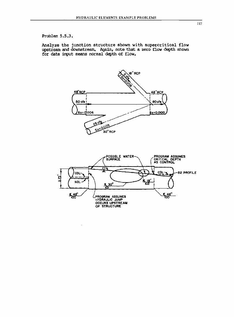
HYDRAULIC ELEMENTS EXAMPLE PROBLEMS
Problem 5.5.3.
Analyze the junction structure shown with supercritical flow upstIeam and downstream. 1\gain, note that a zero flow depth shown for data input means normal depth of flow.
POSSIBLE WATER 5URF"ACE
30"
PROGRAM ASSUMES HYDRAULIC JUMP OCCURS UPSTREAM OF STRUCTURE
PROGRAM ASSUMES CRITICAL DEPTH AS CONTROL
52 PROF"ILE
117
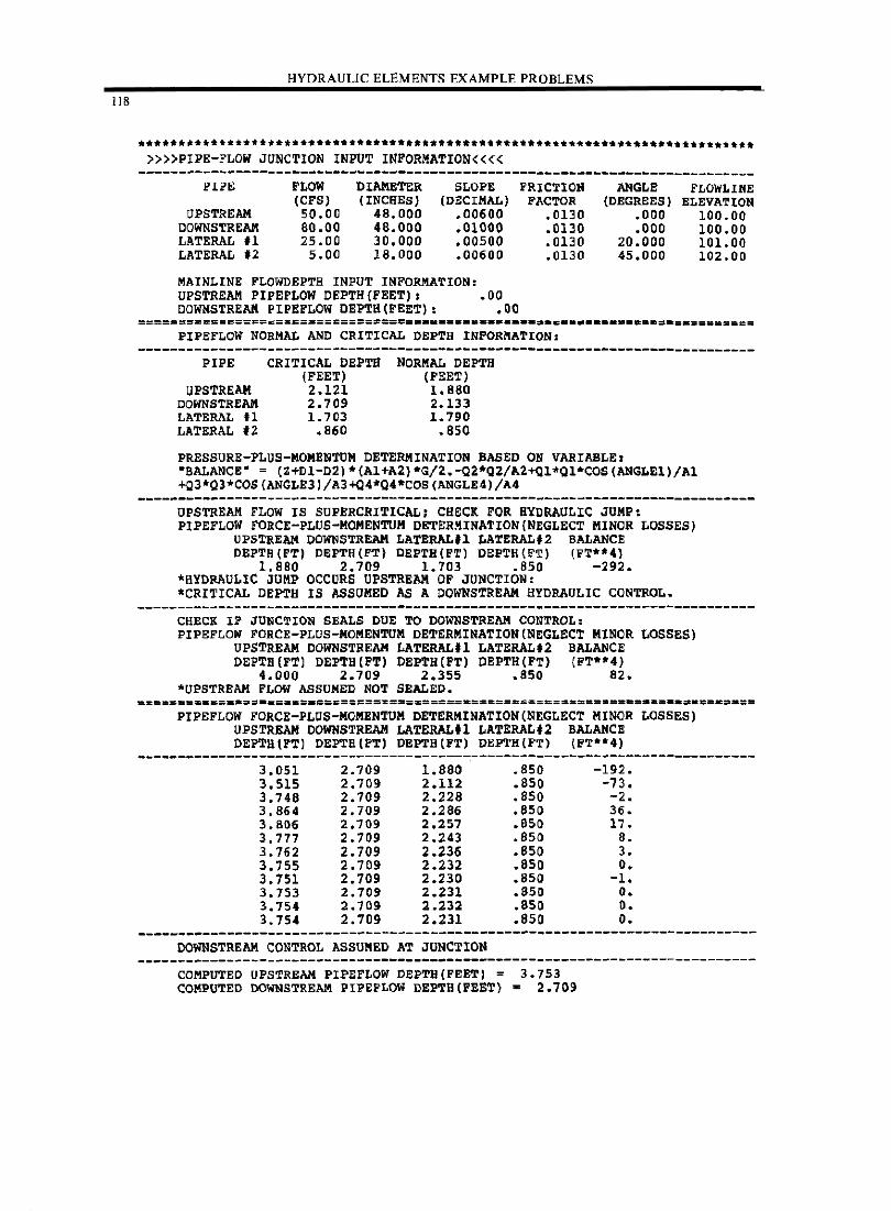
118
HYDRAULIC ELEMENTS EXAMPLE PROBLEMS
**************************************************************************** »»PIPE-FLOW JUNCTION INPUT INFORMATION««
----------------------------------------------------------------------------PIPE
UPSTREAM DOWNSTREAK LATERAL U LATERAL .2
PLOW (CPS) 50.00 80.00 25.00
5.00
DIAMETER (INCHES)
48.000 48.000 30.000 18.000
SLOPE (DECIMAL)
.00600
.01000
.00500
.00600
MAINLINE FLOWDEPTH INPUT INFORMATION: UPSTREAM PIPEFLOW DEPTH(FEET). .00 DOWNSTREAK PIPEFLOW DEPTH (FEET) , .00
FRICTION FACTOR
.0130
.0130
.0130
.0130
ANGLE (DEGREES)
.000
.000 20.000 45.000
FLOWLINE ELEVATION
100.00 100.00 10l.00 102.00
=================================~~.=.=#.=-••• -.-•• ~ ••••• _ •••••• =-:.======== PIPEFLOW NORMAL AND CRITICAL DEPTH INFORMATION:
PIPE
UPSTREAM DOWNSTREAM LATERAL tl LATERAL .2
CRITICAL DEPTH (FEET) 2.121 2.709 1.703
.860
NORMAL DEPTH (FEET) 1.880 2.133 1.790
.850
PRESSURE-PLUS-MOMENTUM DETERMINATION BASED ON VARIABLE. "BALANCE" = (Z+DI-D2)*CA1+A2l*G!2.-QZ*Q2!A2+Ql*Q1*COS(ANGLE1)!A1 +Q3*Q3*COS (ANGLE3)!A3+Q4*Q4*COS (ANGLE4,!A4
UPSTREAM FLOW IS SUPERCRITICAL; CHECK FOR HYDRAULIC JUMP, PIPEFLOW FORCE-PLUS-MOMENTUM DETERMINATION(NEGLECT MINOR LOSSES)
UPSTREAM DOWNSTREAM LATERAL.l LATERAL,2 BALANCE DEPTH(FT) DEPTH(FT) DEPTHCFTl DEPTH(FT) (FT*-4)
1.880 2.709 1.703 .850 -292. 'HYDRAULIC JUMP OCCURS UPSTREAM OF JUNCTION: -CRITICAL DEPTH IS ASSUMED AS A DOWNSTREAM HYDRAULIC CONTROL.
CHECK IF JUNCTION SEALS DUE TO DOWNSTREAM CONTROL: PIPEFLON FORCE-PLUS-MOMENTUM DETERMINATION(NEGLECT MINOR LOSSES)
UPSTREAM DOWNSTREAM LATERAL.l LATERAL.2 BALANCE DEPTH (FTl DEPTH(FT) DEPTH(FT) DEPTH(FT) (FT**4)
4.000 2.709 2.355 .850 82. *UPSTREAM FLOW ASSUMED NOT SEALED.
PIPEFLOW FORCE-PLUS-MOMENTUM DETERMINATION(NEGLECT MINOR LOSSES) UPSTREAM DOWNSTREAM LATERAL.1 LATERAL.2 BALANCE DEPTHIFTJ DEPTB(FT) DEPTH(FT) DEPTH(FT) (FT**4)
3.051 2.709 1.880 .850 -192. 3.515 2.709 2.112 .850 -73. 3.748 2.709 2.228 .850 -2. 3.864 2.709 2.286 .850 36. 3.806 2.709 2.2S7 .eso 17. 3.777 2.709 2.243 .850 8. 3.762 2.709 2.236 .850 3. 3.755 2.709 2.232 .8S0 O. 3.751 2.709 2.230 .850 -1. 3.753 2.709 2.231 .850 O. 3.754 2.709 2.232 .8S0 O. 3.754 2.709 2.231 .850 O.
-----------------------------------------------~----------------------------DOWNSTREAM CONTROL ASSUMED AT JONCTION
----------------------------------------------------------------------------COMPUTED UPSTREAM PIPEFLOW DEPTHCFEETI ~ 3.753 COMPUTED DOWNSTREAM PIPEFLOW DEPTB(FEET) z 2.709
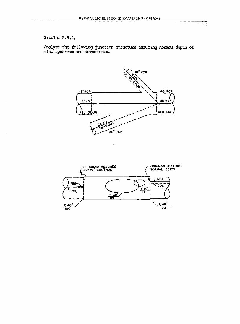
HYDRAULIC ELEMENTS EXAMPLE PROBLEMS
Proolem 5.5.4.
Analyze the following junction structure assuming normal depth of flow upstream and downstream.
I I
60cll : lao I
(
PROGRAM ASSUMES SOFFIT CONTROL.
4S"RCP
PROGRAM ASSUMES NORMAL OEPTH
"" IE. 48" 100
119
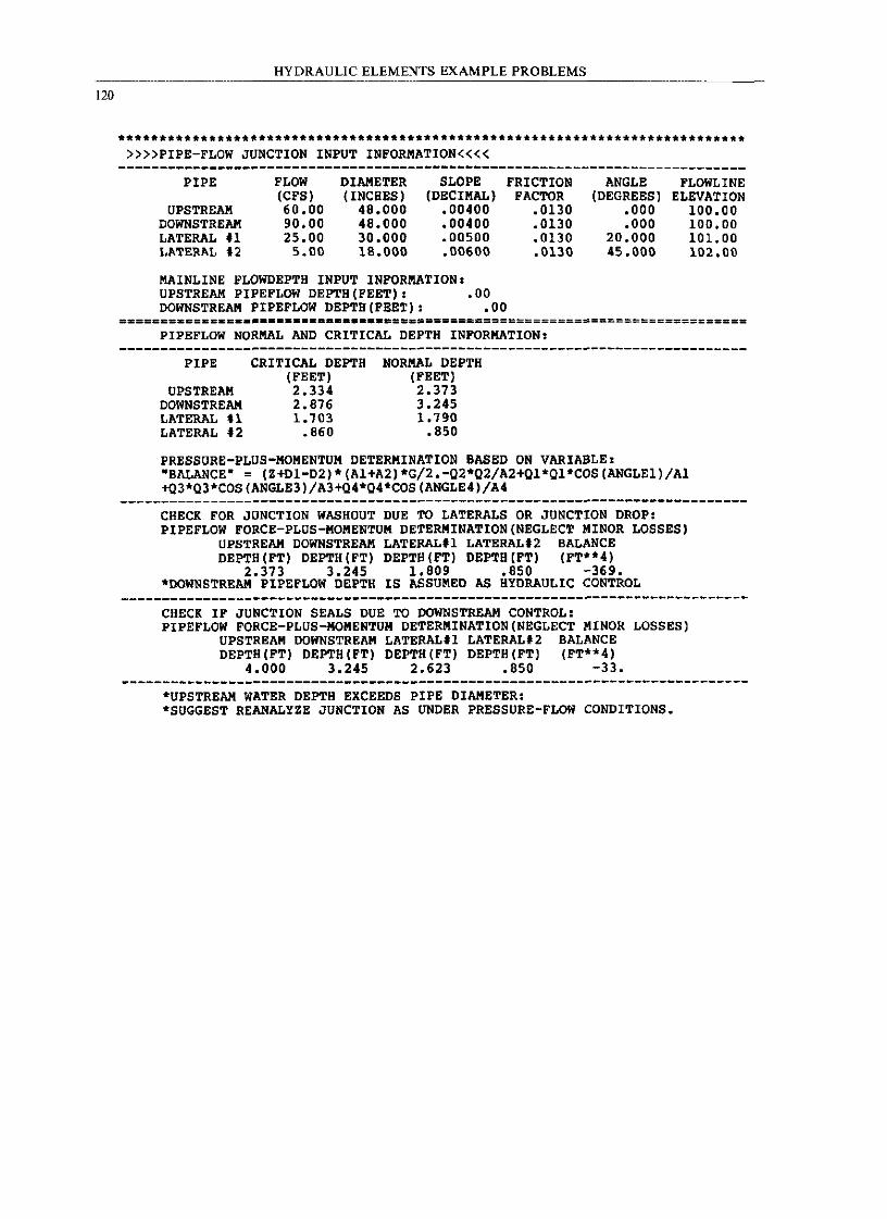
120
HYDRAULIC ELEMENTS EXAMPLE PROBLEMS
***********************.*****.*************** •••• *** •• **** •• **************** »»PIPE-FLOW JUNCTION INPUT INFORMATION««
----------------------------------------------------------------------------PIPE
UPSTREAM DOWNSTREAM LATERAL fl LATERAL 12
FLOW (CFS) 60.00 90.00 25.00
5.00
DIAMETER (INCHES)
48.000 48.000 30.000 18.000
SLOPE (DECIMAL)
.00400
.00400
.00500
.00600
MAINLINE FLOWDEPTH INPUT INFORMATION: UPSTREAM PIPEFLOW DEPTH(FEET). .00 DOWNSTREAM PIPEFLOW DEPTH(FEET): .00
FRICTION FACTOR
.0130
.0130
.0130
.0130
ANGLE (DEGREES)
.000
.000 20.000 45.000
FLOWLINE ELEVATION
100.00 100.00 101. 00 102.00
============ ••••••••••••••••••••• =========================================== PIPEFLOW NORMAL AND CRITICAL DEPTH INFORMATION:
PIPE
UPSTREAM DOWNSTREAM LATERAL H LATERAL t2
CRITICAL DEPTH (FEET) 2.334 2.876 1. 703
.860
NORMAL DEPTH (FEET) 2.373 3.245 1.790
.850
PRESSURE-PLUS-MOMENTUM DETERMINATION BASED ON VARIABLE. "BALANCE" = (Z+DI-D2)*(Al+A2)*G/2.-02*02/A2+01*Ol*COS(ANGLEl)/Al +Q3*03*COS(ANGLE3)/A3+04*04*COS(ANGLE4)/A4
CHECK FOR JUNCTION WASHOUT DUE TO LATERALS OR JUNCTION DROP: PIPEFLOW FORCE-PLUS-MOMENTUM DETERMINATION(NEGLECT MINOR LOSSES)
UPSTREAM DOWNSTREAM LATERAL.l LATERALt2 BALANCE DEPTH (FT) DEPTH (FT) DEPTH (FT) DEPTB(FT) (FT·*4)
2.373 3.245 1.809 .850 -369. ·DOWNSTREAM PIPEFLOW DEPTH IS ASSUMED AS HYDRAULIC CONTROL
----------------------------------------------------------------------------CHECK IF JUNCTION SEALS DUE TO DOWNSTREAM CONTROL: PIPEFLOW FORCE-PLUS-MOMENTUM DETERMINATION(NEGLECT MINOR LOSSES)
UPSTREAM DOWNSTREAM LATERALtl LATERALt2 BALANCE DEPTH (FT) DEPTH(FT) DEPTH (FT) DEPTH (FT) (FT··4)
4.000 3.245 2.623 .850 -33.
·UPSTREAM WATER DEPTH EXCEEDS PIPE DIAMETER: .SUGGEST REANALYZE JUNCTION AS UNDER PRESSURE-FLOW CONDITIONS.
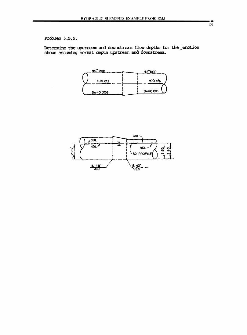
HYDRAULIC ELEMENTS EXAMPLE PROBLEMS
Prcblem 5.5.5.
Determine the upstream and downstream flow depths for the junction shown assuming norml depth upstream and downstream.
-",
'" N
4S"RCP
100 cIs a-
50=0.006
IL 48" 100
/
COL
\L42" 99.5
42"RCP
IOOch •
So=O.OIO
-., ~ en N N
121
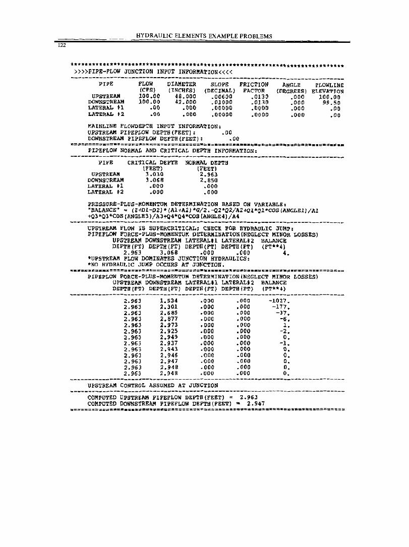
122
HYDRAULIC ELEMENTS EXAMPLE PROBLEMS
****~********.*****.******w***********.*************.* ***************_****** »»PIPE-FLOW JUNCTION INPUT INFORMATION«« ----------------------------------------------------~-----------------------PIPE
UPSTREAII DOlrnSTREAII LATERAL n LA'l"ERAL .2
FLOW (CFS) 100.00 100.00
.00
.00
DIAMETER (INCHES)
48.000 41.000
.000
.000
SLOPE (DECIMAL)
.00600
.01000
.00000
.00000
MAINLINE FLOWDEPTR INPUT INFORMATION; UPSTREAM PIPEFLOW DEPTB(FEET); .00 DO!OliSTREAII PIPEFLOW DEPTH(FEET): .00
FRICTION FACTOR
.0130
.0130
.0000
.0000
PIPEFLOW NORMAL AND CRITICAL DEPTH INFORMATION;
ANG~E (DI!GREES I
.000
.000
.000
.000
FLOWLIN~ ELEVATION
100.00 99.50
.00
.00
------------------------------------------------------------.---------------PIPE
UPSTREAM DOlrnSTREAII LATERAL H LATERAL t2
CRITICAL DEPTH (FEET) 3.030 3.068
.000
.000
NORMAL DEPTH (FEET) 2.963 2.850
.000
.000
PRESSORE-PLOS-MOMENTUM DETERMINATION BASED ON VARIABLE. "BALANCE" ~ (Z+D1-D2)·(Al+A2)·G/2.-Q2·Q2/A2~1·Ql·COS(ANGLE1)/Al +Q3*Q3*C05(ANGLE3)/A3+Q4*04*COS(ANGLE4)/A4
--------------------------------------------~-------------------------------UPS~REAM FLOW lS SUPERCRITICAL: CHECK FOR HYDRAULIC JUMp; PIPEFLOW FORCE'PLUS-MOMENTU~ DETERMINATION(NEGLECT MINOR LOSSES)
UPSrEEAM DOWNSTREAM LATERAL.l LATERALi2 BALANCE DEPTH (FT) DEPTH (FT) DEPTB(FT) DEPTR(FT) (FT**4)
2.963 3.068 .000 .000 4. *UPSTRE~ FLOW DOMINATES JUNCTION HYDRAULICS: "NO HYDRAULIC JUMP OCCURS AT JUNCTION.
PIPEP~OW FORCE-PLUS-MOMENTUM DETERMINATION/NEGLECT MINOR LOSSES) UPSTREAIoI DOWNSTREAIoI LATEIlALU LATERALt2 BALANCE DEPTR(F~) DEPTH (FT) DEPTH{FTj DEPTH/FTj (FT"')
~---------------------------------------------------------------------------2.963 1.534 .000 .000 -1027 • 2.963 2.301 .000 • 000 -177 • 2.96, 2.685 .000 • 000 -37 • 2.963 2.877 .000 .000 -6. 2.963 2.973 • 000 • 000 1 • 2.963 2.925 .000 • 000 -2 • 2.963 2.949 .000 • 000 O • 2.963 2.937 .000 • 000 -1 • 2.963 2.943 .000 .000 O. 2.963 2.946 .000 • 000 O • 2.963 2.947 .000 • 000 O • 2.963 2.948 • 000 .000 O • 2.963 2.948 .000 • 000 O •
UPSTREAM CONTROL hSSUMED AT JUNCTION -----------------------------~----------------------------------------------
COMPUTED UPSTREAM PIFEfLOW DEPTP(FEET) = 2.963 COMPUTED DOWNSTREAM PIPEFLOW DEPTH(fEET) - 2.947
=======~====.= •• =.=~.~.==~==============~======~=====%=.==.=====~===========
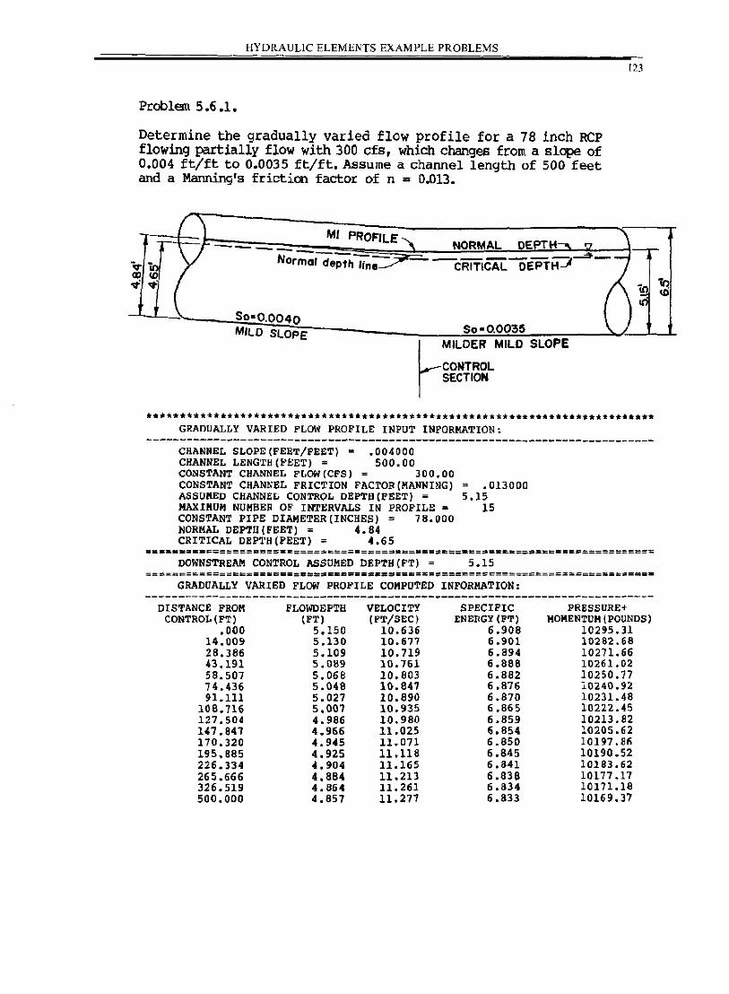
HYDRAULIC ELEMENTS EXAMPLE PROBLEMS
123
Problem 5.6.1.
Determine the gradually varied flow profile for a 78 inch RCP flowing partially flow with 300 cfs, which changes from a slope of 0.004 ft/ft to 0.0035 ft/ft. Assume a channel length of 500 feet and a Manning's friction factor of n = 0.013.
.,. Q) ..,:
/ ...:--:. 1 MI PROFILE,
DEPTH---.. '" -F ____ NORMAL
Nor~' de;th/;';,~--cRi'i'iCAL OEPTH:::;t-~ -''ll: CD ..,:
! SO-0.0040 MILO SLOPE So-0.0035
~MILoER MILD SLOPE
CONTROL SECTION
iQ I III
)
•••••• * •••••••••••••••• **.** ••• ********** ••• * ••••• ****** •• ***.********.***** GRADUALLY VARIED FLOW PROFILE INPUT INFORMATION,
----------------------------------------------------------------------------CHANNEL SLOPE(FEET/FEET) = .004000 CHANNEL LENGTH (FEET) = 500.00 CONSTANT CHANNEL FLOW(CFS) = 300.00 CONSTANT CHANNEL FRICTION FACTOR(MANNING) ASSUMED CHANNEL CONTROL DEPTB(FEET) = MAXIMUM NUMBER OF INTERVALS IN PROFILE = CONSTANT PIPE DIAHETER(INCHES) = 78.000 NORMAL DEPTH(FEET) = 4.84 CRITICAL DEPTH(FEET) = 4.65
.013000 5.15
15
==~================~=============_==========~==.~===E=_====_================
DOWNSTREAM CONTROL ASSOMED DEPTH{FT) = 5.15 ===:==::=~=:===:====.==.====~=====~.=======~===============================-
GRADUALLY VARIED FLOW PROFILE COMPUTED INFORMATION:
DISTANCE FROM CONTROt. (FT)
.000 14.009 28.386 43.191 58.507 74.436 91.111
108.716 127.504 147.B41 170.320 195.B85 226.334 265.666 326.519 500.000
FLOWDEPTB (FT)
5.150 5.130 5.109 5.089 5.068 5.048 5.027 5.007 4.986 4.966 4.945 4.925 4.904 4.884 4.864 4.857
VELOCITY (FT/SEC)
10.636 10.671 10.719 10.761 10.803 1t).841 10.890 10.935 10.980 11.025 11.071 11.11B 11.165 11.213 11.261 11.277
SPECIFIC ENERGY (FT)
6.908 6.901 6.894 6.888 6.882 6.876 6.870 6.865 6.859 6.854 6.850 6.845 6.841 6.838 6.834 6.833
PRESSURE+ MOMENTUM (POUNDS)
10295.31 10282.68 10271.66 10261. 02 10250.77 10240.92 10231. 48 10222.45 10213. ~2 10205.62 10197.86 10190.52 10183.62 10177.17 10171.18 10169.37
in <D
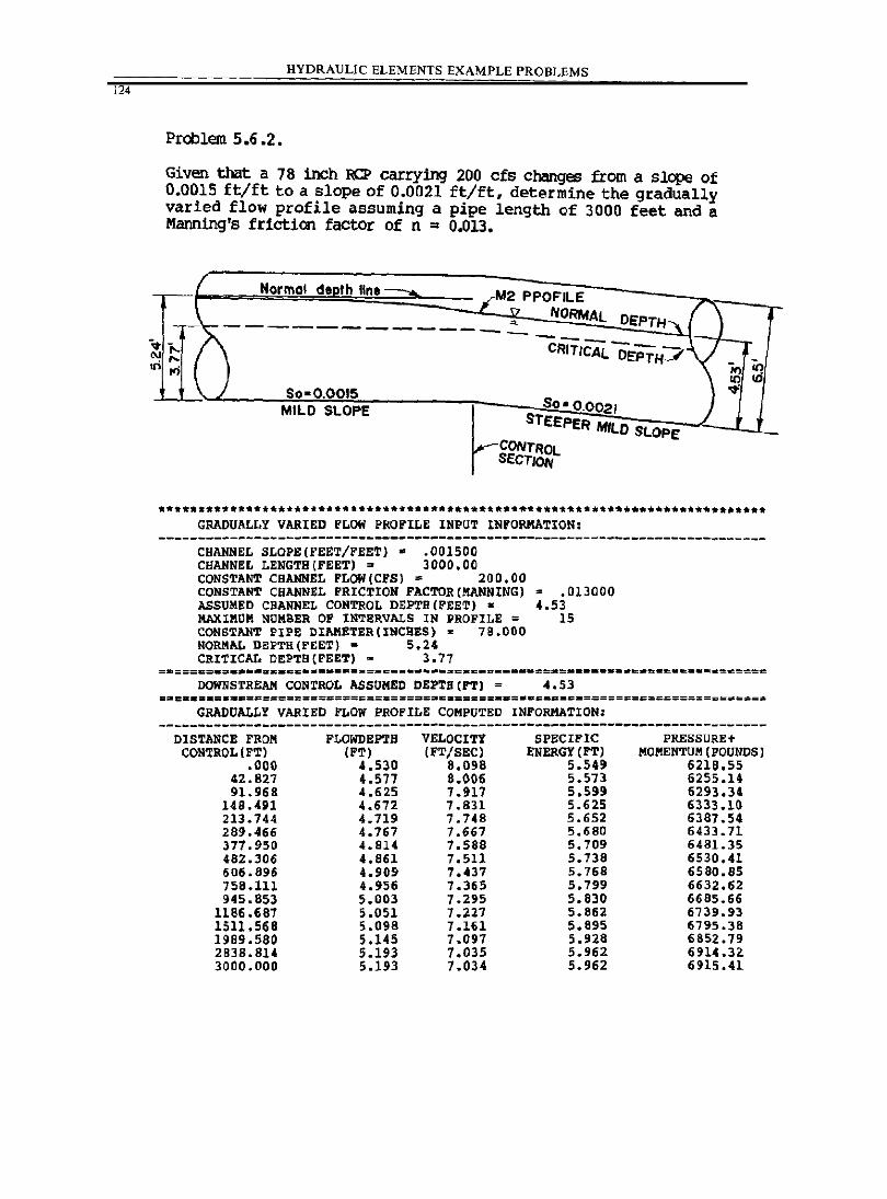
124
HYDRAULIC ELEMENTS EXAMPLE PROBLEMS
Problem 5.6 .2 •
Given that a 78 inch RCP carrying 200 cfs changes from a slc:pe of 0.0015 ft/ft to a slope of 0.0021 ft/ft, determine the gradually varied flow profile assuming a pipe length of 3000 feet and a Manning's friction factor of n = 0.013.
/ Normal deDth IIne __ "M2 PPOFILE
,., NORMAL DEPTH,
/ "\ '" I --- --/\ v- cRiT,CAL DEPTH"""'· ru"" '-...
r<j H) I()
10 iii So-0.0015 I ~
MILO SLOPE SO-0.0021 .I STEEPER MILO S 1 LOPE
-************.*.*.********.*.******** ••• ***-********.***** •• * ••••••••••••• ** GRADUALLY VARIED FLOW PROFILE INPUT INFORMATION:
----------------------------------------------------------------------------CHANNEL SLOPE(FEET/FEET)· .001500 CHANNEL LENGTH(FEET) ~ 3000.00 CONSTANT CHANNEL FLOW (CFS) = 200.00 CONSTANT CHANNEL FRICTION FACTOR(MANNING) = .013000 ASSUMED CHANNEL CONTROL DEPTH(FEET) - 4.53 MAXIMUM NUMBER OF INTERVALS IN PROFILE = 15 CONSTANT PIPE DIAMETER(INCHES) = 78.000 NORMAL DEPTH(FEET) = 5.24 CRITICAL DEPTB{FEET) - 3.77
DOWNSTREAM CONTROL ASSUMED DEPTB{FT) = 4.53
GRADUALLY VARIED FLOW PROFILE COMPUTED INFORMATION:
DISTANCE FROII FLOWDEPTB VELOCITY SPECIFIC CON'lROL{FT) (FT) (PT/SEC) ENERGY (FT)
.000 4.530 8.098 5.549 42.827 4.577 8.006 5.513 91.968 4.625 7.917 5.599
148.491 4.672 7.831 5.625 213.744 4.719 7.748 5.652 289.466 4.767 7.667 5.680 377.950 4.814 7.588 5.709 482.306 4.861 7.511 5.738 606.896 4.909 7.437 5.768 758.111 4.956 7.365 5.799 945.853 5.003 7.295 5.830
ll86.687 5.051 7.227 5.862 1511.568 5.098 7.IU 5.895 1989.580 5.145 7.097 5.928 2838.8U 5.193 7.035 5.962 3000.000 5.193 7.034 5.962
PRESSURE ... MOMENTUM (POUNDS)
621S.55 6255.14 6293.34 6333.10 6387.54 6433.71 6481.35 6530.41 6580.85 6632.62 6685.66 6739.93 6795.38 6852.79 6914.3Z 6915.41
•
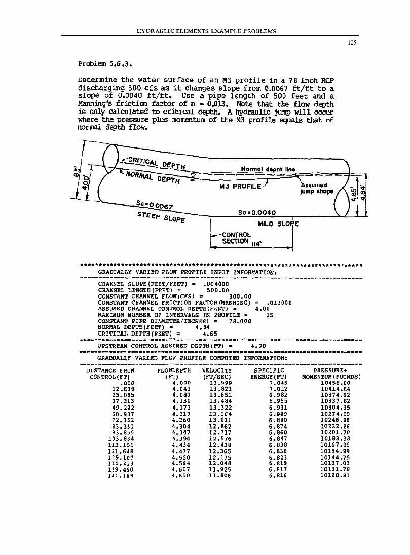
HYDRAULIC ELEMENTS EXAMPLE PROBLEMS
Pt:oblern 5.6.3.
Determine the water surface of an M3 profile in a 78 inch RCP discharging 300 cfs as it changes slope from 0.0067 ft/ft to a Slope of 0.0040 ft/ft. Use a pipe length of 500 feet and a Manning's friction factor of n = 0.013. Note that the flow depth is only calculated to critical depth. A hydraulic jUmp will occur where the pressure plus momentum of the M3 profile equals that of normal depth flow.
# /
.J ).r...E..R.!!!.CAl DEI' "in t - ""-"'_-IH Normal dOPth IIno <ti b .... NORItfAl.. DEPTH -y--- -- - ---
125
"' ~ ( M~ FROFII..E)
jump Ihope ~ "~-'(. ;r
J CIl
50-0.0067 ~
STEEP SLOPE 50-0.0040
MILD SLOP.E
~CONTROL SECTION 114'
*** •• -*****._ •••• ***.-.* •••• -*.*.-** ••• *****.*_.-••• ** **********~*********** GRADUALLY VARIED FLOW PROFILE INFUT INFORMATION.
----------------------------------------------------------------------------CHANNEL SLOPE(FEET/FEET)· .004000 CHANNEL LENGTH(FEET) = 500.00 CONSTANT CHANNEL FLOW(CFS) = 300.00 CONSTANT CHANNEL FRICTION FACTOR(MANNING) ASSUMED CHANNEL CONTROL DEPTE(FEeT) • MAXIMUM NUMBER OF INTERVALS IN PROFILE = CONSTANT prp~ DrAMETtR(INCH~SJ = 7B.OOO NORMAL DEPTH(FEET) • 4.84 CRITICAL DEPTH (FEET) = 4.65
= .013000 4.00
IS
~_= __ =_: ____ =============z=;==========~============~======================== UPSTREAM CONTROL ASSUMED DEP~H(FTI - 4.00
GRADUALLY VARIED FLOW PROFILE COMPUTED INFORKATION:
DISTANCE FROM CONTROL (FT)
.000 12.639 25.085 37.313 49.292 60.987 72.352 83.331 93.855
103.834 113.151 121.648 129.107 135.213 139.490 141.169
fLOfiDEPTll (FT)
4.000 4.043 4.087 4.130 4.173 4.217 4.260 4.304 4.347 4.390 4.434 4.477 4.520 4.564 4.607 4.650
VELOCITY (fT/SEC)
13.999 13 .823 13 .651 13.484 13.322 13.164 13 .011 12.862 12.717 12.576 12.438 12.305 12.175 12.048 11.925 11.806
SPECII'IC ENERGY (FT)
7.045 7.012 6.982 6.955 6.931 6.909 6.890 6.814 6.860 6.847 6.838 5.830 6.823 6.819 5.817 Ii. 816
PRESSURE+ MOIlENTUM(POUNDS)
10459.60 10414.64 10374.62 10337.62 10304.35 10274.09 10246.96 10222.86 10201. 70 10183.36 10167.85 10154.99 10144.75 10137 .03 10131. 78 10128.91
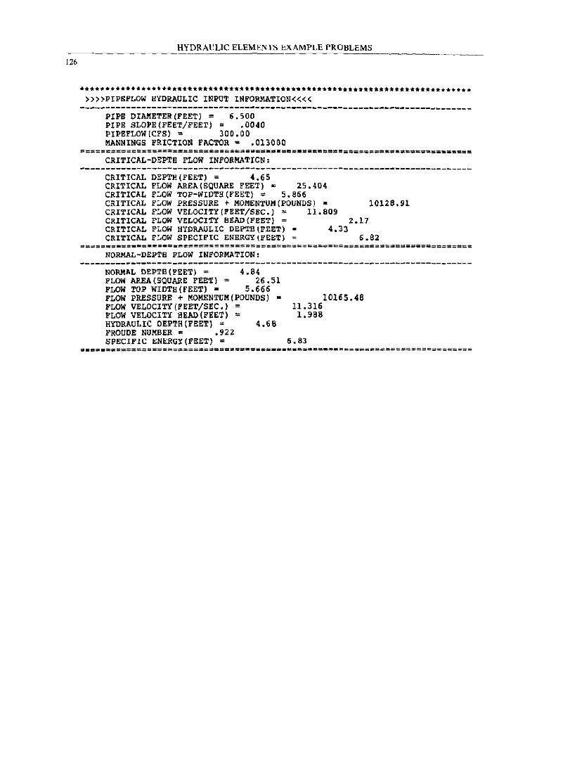
126
HYDRAULIC ELEMENTS EXAMPLE PROBLEMS --------
••• **.*.* •• *.*.~.***.******~***~.***.***.***.***.******.*.**.***********+.*. »»PIPEFLOW HYDRAULIC INPUT INFORMATION««
------------------.------------------------.---.---.------------------------PIPE DIAMETER(FEET) = 6.500 PIPE SLOPE(FEET/FEET)' .0040 PIPEFLOW(CFS) = 300.00 MANNINGS FRICTION FACTOR a .013000
CRITICAL-DEPTH FLOW INFORMATION:
CRITICAL DEPTH(FEET) = 4.65 CRITICAL FLOW AREA (SQUARE FEET) = 25.404 CRITICAL FLOW TOP-WIDTH (FEET) = 5.866 CRITICAL FLOW PRESSURE + MOMENTUM (POUNDS) • 10128.91 CRITICAL FLOW VELOCITY (FEET/SEC.) = 11.809 CRITICAL FLOW VELOCITY BEAD (FEET) = 2.17 CRITICAL FLOW HYDRAULIC DEPTH(FEET) • 4.33 CRITICAL FLOW SPECIFIC ENERGY(FEET) = 6.82
=====-=-==--=-~=-===================================~=======================
NORMAL-DEPTH FLOW INFORMATION:
NORMAL DEPTB(PEET) = 4.84 FLOW AREA (SQUARE FEET) = 26.51 FLOW TOP WIDTH(FEET)· 5.666 FLOW PRESSURE + MOMENTUM(PDUNDS) = FLOW VELOCITY(FEET/SEC.) = FLOW VELOCITY BEAD (FEET) = HYDRAULIC DEPTB(FEET) ~ 4.68 FROUOE NUMBER = .922 SPECIFIC ENERGY(FEET) =
10165.48 11.316 1.988
6.83
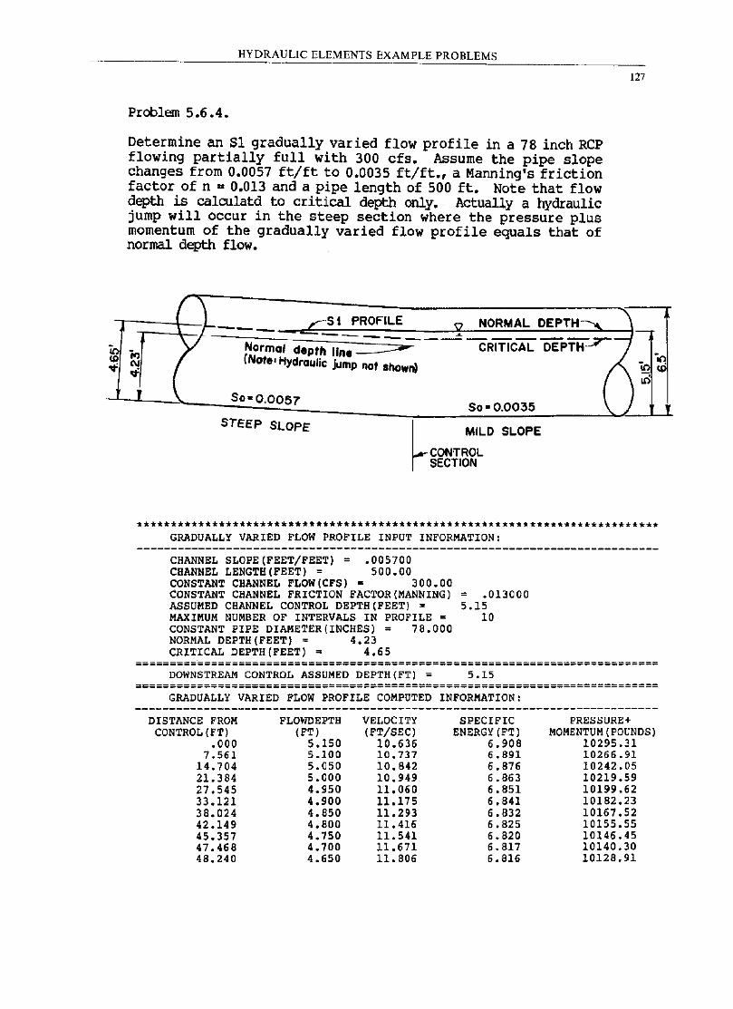
It) <D
'"
HYDRAULIC ELEMENTS EXAMPLE PROBLEMS
Problem 5.6.4.
Determine an Sl gradually varied flow profile in a 78 inch Rep flowing partially full with 300 cfs. Assume the pipe slope changes from 0.0057 ft/ft to 0.0035 ft/ft., a Manning's friction factor of n = 0.013 and a pipe length of 500 ft. Note that flow depth is calculatd to critical depth only. Actually a hydraulic jump will occur in the steep section where the pressure plus momentum of the gradually varied flow profile equals that of normal depth flow.
/"'1 I I ,-5 t PROFILE
'" NORMAL DEPTH---..... ---7 - -- . - ~-
'" Norma' depth line ====- CRITICAL DEPTH (Note. Hydraulic jump nol shown) '" '" I (
127
I-
it>
lit) 50-0.0057
50'0.0035 \. ) STEEP SLOPE
~ MILD SLOPE
CONTROL SECTION
I-~
**************************************************************************** GRADUALLY VARIED FLOW PROFILE INPUT INFORMATION:
CHANNEL SLOPE(FEET/FEET) = .005700 CHANNEL LENGTH(FEET) = 500.00 CONSTANT CHANNEL FLOW(CFS) ~ 300.00 CONSTANT CHANNEL FRICTION FACTOR(MANNING) ASSUMED CHANNEL CONTROL DEPTH (FEET) = MAXIMUM NUMBER OF INTERVALS IN PROFILE = CONSTANT PIPE DIAMETER(INCHES) = 78.000 NORMAL DEPTH(FEET) = 4.23 CRITICAL DEPTH(FEET) = 4.65
= .013000 5.15
10
DOWNSTREAM CONTROL ASSUMED DEPTH(FT) = 5.15 ============================================================================
GRADUALLY VARIED FLOW PROFILE COMPUTED INFORMATION:
DISTANCE FROM FLOWDEPTH VELOCITY SPECIFIC PRESSURE+ CONTROL (FT) (FT) (FT/SEC) ENERGY (FT) MOMENTUM (POUNDS)
.000 5.150 10.636 6.908 10295.31 7.561 5.100 10.737 6.891 10266.91
14.704 5.050 10.842 6.876 10242.05 21. 384 5.000 10.949 6.863 10219.59 27.545 4.950 11. 060 6.851 10199.62 33.121 4.900 11.175 6.841 10182.23 38.024 4.850 11.293 6.832 10167.52 42.149 4.BOO 11.416 6.825 10155.55 45.357 4.750 11.541 6.820 10146.45 47.468 4.700 11.671 6.817 10140.30 48.240 4.650 11.806 6.816 10128.91
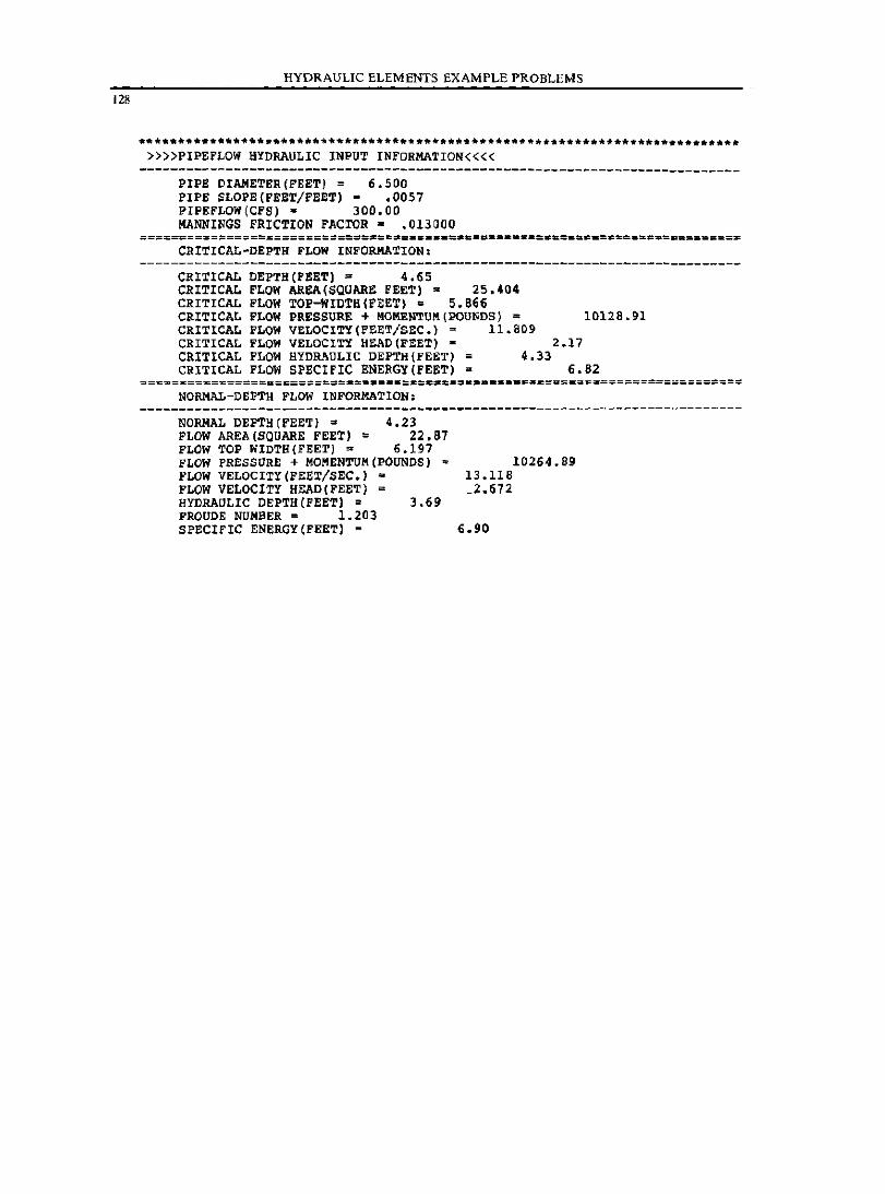
HYDRAULIC ELEMENTS EXAMPLE PROBLEMS ---------
128
.**** •• ************* ••• ~**~**.**~***** ••••• **.* •• *.***** •• ****.* •• *.**.***** »»PIPEFLOW HYDRAULIC INPUT INFORMATIO~««
----------------------------------------------------------------------------PIPE DIAMETER(FEET) = 6.500 PIPE SLOPE(FEBT/FEET)· .0057 PIPEFLOW(CFS) = 300.00 MANNINGS FRICTION FACTOR = .013000
CRITICAL-DEPTH FLOW INFORMATION:
CRITICAL DEPTH(FEET) = 4.65 CRITICAL FLOW AREA (SQUARE FEET) = 25.404 CRITICAL FLOW TOP-WIDTH(FEET\ = 5.866 CRITICAL FLOW PRESSURE + ~O~ENTU~(POUNDS) = 10128.91 CRITICAL FLOW VELOCITY(FEET/SEC.) = 11.809 CRITICAL FLOW VELOCITY HEAD(FEET) • 2.17 CRITICAL FLOW HYDRAULIC DEPTH(FEET) = 4.33 CRITICAL FLOW SPECIFIC ENERGY(FEET) = 6.62
NORMAL-DEPTa FLOW INFORMATION,
NORMAL DEPTB(FEET) = 4.23 FLOW AREA (SQUARE FEET) = 22.67 FLOW TOP WIDTH(FEET) = 6.197 FLOW PRESSURE + MOMENTUM (POUNDS) = FLUW VELOCITY(FEET/SEC.) = FLOW VELOCITY HEAD(FEETJ = HYDRAULIC OEPTH(FEETI • 3.69 FROUDE NUMBER = 1.203 SPECIFIC ENERGY(FEETI =
10264.89 13.118 _2.672
6.90
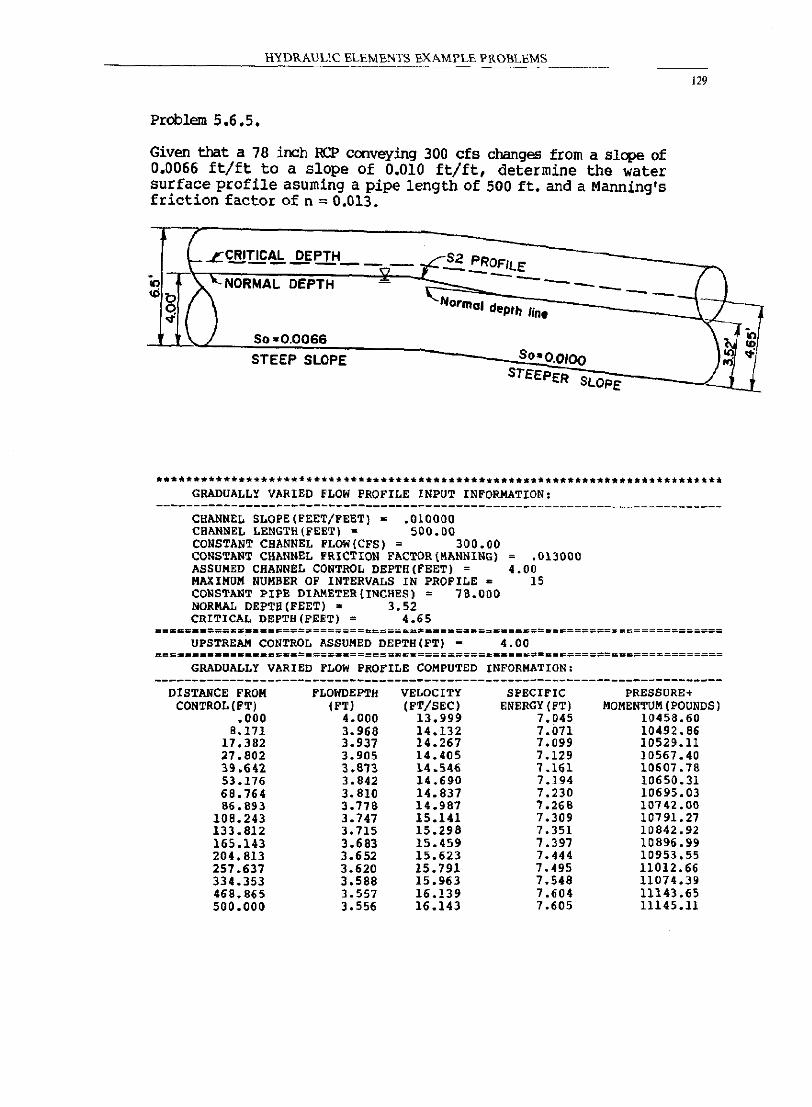
HYDRAULIC ELEMENTS EXAMl'L£ l'ROBLEMS
129
Problem 5.6.5.
Given that a 78 inch RCP conveying 300 cfs changes from a slope of 0.0066 ft/ft to a slope of 0.010 ft/ft, determine the water surface profile asuming a pipe length of 500 ft. and a Manning's friction factor of n = 0.013.
I
LLCRITICAL DEPTH_
~~~NORMAL DEPTH <D-
8. ) ""( ) So-0.0066
STEEP SLOPE
-n-
GRADUALLY VARIED fLOW PROFILE INPUT INFORMATION:
CHANNEL SLOPE(FEET/FEET) = .010000 CHANNEL LENGTH(FEETJ = 500.00 CONSTANT CHANNEL FLOW{CFS) = 300.00 CONSTANT CHANNEL FRICTION FACTOR(~ANNINGI ASSUMED CHANNEL CONTROL DEPTH(FEET) = MAXIMUM NUMBER OF INTERVALS IN PROFILE • CONSTANT PIPE DI~ETER(INCHES) = 78.000 NORMAL DEPTB(FEET) • 3.52 CRITICAL DEPTH(FEET) = 4_65
.013000 4.00
15
== •• = •• ===K.====~==================~C====~.=======;========================= UPSTREAM CONTROL ASSUMED DEPTH(FT) = 4.00
GRADUALLY VARIED FLOW PROFILE COMPUTED INFORMATION:
DISTANCE FROM CONTROL (FT)
.000 8.171
17.382 27.802 39.642 53.176 68.764 86.893
108.243 133.812 165.143 204.813 257.637 334.353 468.865 500.000
f'LOWDEPTH (FT)
4.000 3.968 3.937 3.905 3.an 3.842 3.810 3.778 3.747 3.115 3.683 3.652 3.620 3.588 3.557 3.556
VELOCITY (FT/SEC)
13.999 14.132 14.267 14.405 14.546 14.690 14.837 14.987 15.141 15.298 15.459 15.623 15.791 15.963 16.139 16.143
SPECIFIC ENERGY (FT)
7.045 7.071 7.099 7.129 1.161 7.194 7.230 7.268 7.309 7.351 7.397 7.444 7.495 7.548 7.604 7.605
PRESSURE+ MOMENTUM (POUNDS)
10458.60 10492.86 10529.ll 10567.40 10607.78 10650.31 10695.03 10742.00 10791.27 10842.92 10896.99 10953.55 11012.66 11074.39 11143.65 11145.11
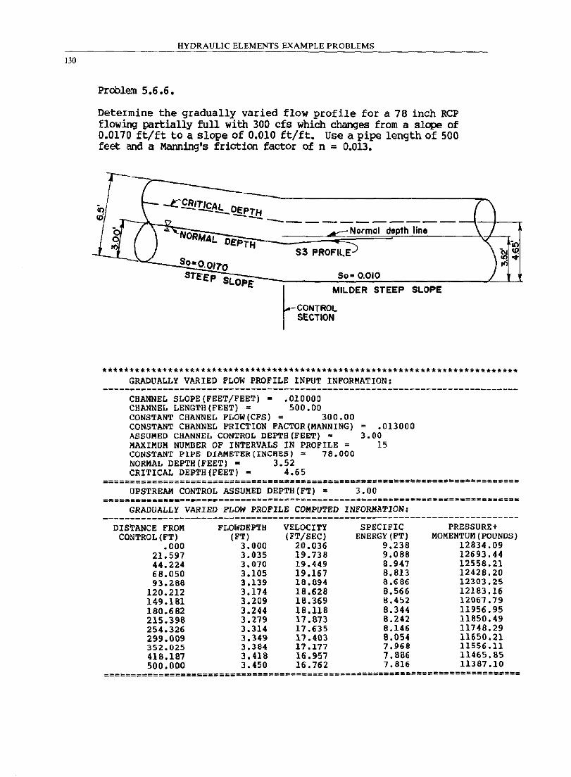
130
HYDRAULIC ELEMENTS EXAMPLE PROBLEMS
Problem 5.6.6.
Determine the gradually varied flow profile for a 78 inch Rep flowing partially full with 300 cfs which changes from a slope of 0.0170 ft/ft to a slope of 0.010 ft/ft. Use a pipe length of 500 feet and a Manning's friction factor of n = 0.013.
-1 f
in ~ -CfBJ!!£Al OE "\ <D \ _-!,TH ( "T"- {'? -...... ___
~.f f \ "" ~Normal depth line \ .... NORMAl OEPTH \'" "*
"i 53 PROFIL.E ./ SooO.OI7'O }:!l of"
So· 0.010 J STEEP SLOP E
~ MILDER STEEP SLOPE
CONTROL SECTION
•••• * ••• ***** •• **** •• **** ••••• *.**** ••••• * ••••••••• * •••• *.* •• *.**.* ••• ****** GRADUALLY VARIED FLOW PROFILE INPUT INFORMATION:
CHANNEL SLOPE(FEET/FEET) = .010000 CHANNEL LENGTH(FEET) = 500.00 CONSTANT CHANNEL FLOW(CFS) = 300.00 CONSTANT CHANNEL FRICTION FACTOR(MANNING) ASSUMED CHANNEL CONTROL DEPTB(FEET) = MAXIMUM NUMBER OF INTERVALS IN PROFILE = CONSTANT PIP~ DIAM~T~R(INCHES) = 78.000 NORMAL DEPTH(FEET) = 3.52 CRITICAL DEPTB(FEET) = 4.65
.013000 3.00
15
==========================================================Z~=.B==.==========
UPSTREAM CONTROL ASSUMED DEPTH(FT) = 3.00
GRADUALLY VARIED FLOW PROFILE COMPUTED INFORMATION:
DISTANCE FROM CONTROL (FT)
.000 21.597 44.224 68.050 93.288
120.212 149.181 180.682 215.398 254.326 299.009 352.025 418.187 500.000
FLOWDEPTH (FT)
3.000 3.035 3.070 3.105 3.139 3.174 3.209 3.244 3.279 3.314 3.349 3.364 3.418 3.450
VELOCITY (FT/SEC)
20.036 19.738 19.449 19.167 18.694 18.628 18.369 18.118 17.873 17.635 17.403 17.177 16.957 16.762
SPECIFIC ENERGY (FT)
9.238 9.088 8.947 8.813 8.686 8.566 8.452 8.344 B.242 8.146 B.054 7.969 7. BB6 7.616
PRESSURE+ MOMENTUM (POUNDS)
12834.09 12693.44 12558.21 12428.20 12303.25 12183.16 12067.79 11956.95 11850.49 11748.29 11650.21 11556.11 11465.85 11387.10
;=========================a===~======================&======================
REFERENCES
Brater, E.F. and King, H.W., "Handbook of Hydraulics for the Solution of Hydraulic Engineering Problems, Sixth Edition,· Md;raw-Hill Book Co., New York, (1976).
Daugherty, R.L. and Franzini, J.B., "Fluid Mechanics with Engineering AWlicat1ons,· McGraw-Hill Book Co., New York, (1977).
Hromadka II, T.V., Clements, J.N., and Saluja, H., ·Computer Methods in Urban Watershed Hydraulics", Lighthouse Publications, Mission Viejo, California, 1984.
Hromadka II, T.V., Clements, J.N., and Guymon, G.L., -Guidelines for Interactive Software in Water Resources Engineering,- Water Resources Bulletin, Feb. (1983c) •
Hromadka II, T.V., Durbin, T.J. and DeVries, J.J., "Computer Methods in Water Resources", Lighthouse Publications, Mission ViejO, California, (1985).
Koutitas, C.G., "Elements of Computational Hydraulics" r Pentech Press, (1983).
131