Embed Size (px)
Citation preview

Computational modeling and Constructal Design
method applied to the geometric optimization of
stiffened steel plates subjected to uniform transverse
load
Marcelo Langhinrichs Cunha, Grégori da Silva Troina, Elizaldo
Domingues dos Santos, Luiz Alberto Oliveira Rocha, Liércio André
Isoldi
Online Publication Date: 20 Jan 2018
URL: http://dx.doi.org/10.17515/resm2017.18st1118
DOI: http://dx.doi.org/10.17515/resm2017.18st1118
Journal Abbreviation: Res. Eng. Struct. Mat.
To cite this article
Cunha ML, Troina GS, Santos ED, Rocha LAO, Isoldi LA. Computational modeling and
Constructal Design method applied to the geometric optimization of stiffened steel plates
subjected to uniform transverse load Res. Eng. Struct. Mat., 2018; 4(3): 139-149.
Disclaimer
All the opinions and statements expressed in the papers are on the responsibility of author(s) and are
not to be regarded as those of the journal of Research on Engineering Structures and Materials (RESM)
organization or related parties. The publishers make no warranty, explicit or implied, or make any
representation with respect to the contents of any article will be complete or accurate or up to date. The
accuracy of any instructions, equations, or other information should be independently verified. The
publisher and related parties shall not be liable for any loss, actions, claims, proceedings, demand or
costs or damages whatsoever or howsoever caused arising directly or indirectly in connection with use
of the information given in the journal or related means.
*Corresponding author: [email protected] DOI: http://dx.doi.org/10.17515/resm2017.18st1118
Res. Eng. Struct. Mat. Vol. 4 Iss. 3 (2018) 139-149 139
Research Article
Computational modeling and Constructal Design method applied to the geometric optimization of stiffened steel plates subjected to uniform transverse load
Marcelo Langhinrichs Cunha1, Grégori da Silva Troina1, Elizaldo Domingues dos Santos1, Luiz Alberto Oliveira Rocha2, Liércio André Isoldi*,1
1 Federal University of Rio Grande - FURG, Rio Grande, RS, Brazil. 2University of Vale do Rio dos Sinos - UNISINOS, São Leopoldo, RS, Brazil.
Article Info Abstract
Article history: Received 18 Nov 2017 Revised 10 Jan 2018 Accepted 15 Jan 2018
The present paper shows a geometric evaluation of stiffened plates subjected to a uniformly distributed transverse loading. For that, it was proposed a set of different geometric configurations through the Constructal Design method, which were numerically simulated. Then, by means of the Exhaustive Search technique, a geometric optimization was performed aiming to minimize the central deflection of the plate. A non-stiffened plate measuring 2.00 m x 1.00 m x 0.02 m was used as reference, then a constant volume ratio ϕ, equals to 0.5, was taken from the reference plate and transformed into longitudinal and transverse stiffeners. The geometric parameters considered as degrees of freedom were: the number of longitudinal (Nls) and transverse (Nts) stiffeners and hs/ts, which is defined by the ratio between the stiffener’s height and thickness. In order to elaborate the computational model, it is used ANSYS Mechanical APDL®, a software based on the Finite Element Method (FEM). From the results, it was possible to determine a power function for each combination of Nls and Nts that accurately described the relation between the central deflection and hs/ts. Furthermore, it was noticed a substantial influence of the geometric parameters under analyses regarding the studied structural element’s mechanical behavior. Even though the volume was kept constant, the optimized geometry has shown a result 9110 % better compared to the one shown by the reference plate.
© 2018 MIM Research Group. All rights reserved.
Keywords: Numerical simulation, Stiffened plates, Constructal design, Finite element method
1. Introduction
Thin plates are defined as being structural components where the transverse dimension, called thickness, is considerably smaller than the planar dimensions, called width and length [1]. Stiffeners are reinforcement beams attached to the plates longitudinally, transversally or both. The main advantage of incorporating stiffeners into plates is the reduction of the structure’s displacements due to the increase of its moment of inertia, thus avoiding the need to use a thicker plate. Stiffened thin plates are widely used to resist distributed and/or concentrated transverse loads in many structural systems such as bridges, ship hulls, vehicles, oilrigs, buildings and aircraft, among others, mainly due to its great strength-weight ratio [2].
In the past years, many researches have been performed seeking to analyze the behavior of plates reinforced with stiffeners under transverse loading. Yousif et al. [3] presented the relation between the height of one lengthwise stiffener and the strength of a given set of

Cunha et al. / Research on Engineering Structures & Materials 4(3) (2018) 139-149
140
plates clamped on its four edges subjected to a pressure load. Virág [4] by using strength calculation methods investigated the minimum cost geometry of various stiffened plates with different loads, types and even stiffener shapes. Tanaka and Bercin [5] used the Boundary Element Method (BEM) in order to analyze the effect of different cross-sections stiffeners in plates subjected to bending. Bedair [6] investigated the stiffener positioning influence on the stability of thin plate structures under bending and compression combined loads through the Sequential Quadratic Programming (SQP) method. Finally, Silva [7] made a numerical study about ribbed slabs, idealizing it as a plate-beam system and using ANSYS® software to model the slab (with SHELL63 element type) and the ribs (with BEAM44 element type).
Since there are no analytical solutions that effectively describe the stiffened plate’s behavior when subjected to transverse loads, computational models are helpful and important tools in order to analyze these structural components. Therefore, the present study uses the software ANSYS Mechanical APDL®, based on the Finite Element Method (FEM), to build the computational model to numerically simulate the behavior of the different stiffened plates’ geometries derived from the application of the Constructal Design method. Considering the Fig. 1 and starting from a non-stiffened reference plate, the set of geometric configurations of stiffened plates to be analyzed were obtained through a variation of the number of longitudinal stiffeners (Nls), the number of transverse stiffeners (Nts) and the ratio between the stiffeners’ height and thickness (hs/ts), always keeping the total steel volume constant. In addition, for each stiffened plate configuration an equal longitudinal stiffener spacing (Sls) and an equal transverse stiffener spacing (Sts) were adopted. All results were compared through Exhaustive Search technique aiming to obtain the optimum geometry that minimizes the deflection at the center of the plate.
Fig. 1 Stiffened plate P(2,3)
2. Constructal Design Method
The Constructal Design method is based on the Constructal Law: “For a finite-size flow system to persist in time (to survive) its configuration must evolve in such a way that it provides an easier access to the currents that flow through it” [8]. This principle might be used for both predicting natural systems configurations such as river basins, animal design and earth climate; as well as yielding updated designs for engineering applications, for example in the areas of heat transfer, fluid mechanics and mechanic of materials [9].
According to Bejan [10], Constructal Design is a methodology that enables to determine a geometry that leads to the best performance of a system when subjected to a flow. For that, the flow should be malleable and the geometry is deduced from a principle of global performance maximization. Specifically in mechanic of materials problems, as explained in

Cunha et al. / Research on Engineering Structures & Materials 4(3) (2018) 139-149
141
Bejan and Lorente [11], this flow is related with the flow of stresses in the structure. Besides that, it should be imposed global restrictions to the geometry and vary the degrees of freedom.
The goal in the present work is to improve the mechanical behavior of stiffened plates regarding the deflection at its center by varying geometric parameters, yet without changing the plate total volume. In order to do so, it is used a non-stiffened plate as reference, then a fraction 𝜙 of volume is taken from this reference plate and transformed into stiffeners. The volume fraction 𝜙 is given by:
𝜙 = 𝑉𝑠
𝑉𝑟=
𝑁𝑙𝑠(𝑎ℎ𝑠𝑡𝑠)+ 𝑁𝑡𝑠[(𝑏− 𝑁𝑙𝑠𝑡𝑠)ℎ𝑠𝑡𝑠]
𝑎𝑏𝑡 (1)
where, Vs is the reference plate’s volume transformed into stiffeners, Vr is the reference non-stiffened plate’s total volume, Nls and Nts are, respectively, the number of longitudinal and transverse stiffeners, hs represents the height and ts the thickness of the stiffeners. Lastly, a, b and t are, respectively, the length, width and thickness of the reference plate. Thus, all analyzed geometries have the same amount of material, enabling performing a comparative evaluation of their structural performance regarding the transversal deflections.
Seeking to determine the optimal geometry, it was investigated the influence of the degrees of freedom Nls, Nts and hs/ts. It were analyzed 36 combinations of longitudinal and transverse stiffeners equally spaced (see Fig. 1), with the following variation: Nls = 2,3,4,5,6 and 7 and Nts = 2,3,4,5,6 and 7. So, these plates were nominated accordingly with the notation P(Nls , Nts), such as the plate P(2,3) presented in Fig. 1. In addition, it were used sizes of stiffeners’ thickness ranging from 3.75 mm (1/8 in) to 76.2 mm (3 in), therefore the hs/ts ratio derives from these predefined ts sizes. Moreover, the height hs complies two geometric constraints: it should not be higher than 300 mm, in order to avoid a substantial disproportionality between the stiffener’s height and the plate’s dimensions; and the ratio hs/ts should be greater than 1 to avoid the thickness from being greater than the height.
3. Computational Modeling
The present work uses computational models based on the Finite Element Method (FEM) in order to numerically simulate the mechanical behavior of plates under a distributed transverse load. Basically, a finite element analysis consists of four steps: creation of the model geometry, mesh generation, application of the load and boundary conditions and the solution of the problem [12].
When analyzing the linear elastic behavior of mechanical structures through the FEM, it is used the virtual work principle in order to solve the problem. Concerning static analysis, the effects of damping and inertial forces are not taken into account when estimating the magnitude of displacements and internal forces at any part of the system, which are obtained through the algebraic equation [13]:
[𝐾] . {𝑈} = {𝐹} (2)
where, [K] is the stiffness matrix, {U} is the unknown nodal displacement vector and {F} is the external forces vector. The stiffness matrix [K] is defined by the stress-strain and strain-deflection relations of the structure.
Nowadays, a wide variety of software adopt a FEM approach to analyze engineering problems, for instance the ANSYS Inc. software package, whose applications range from static structural to fluid dynamics problems. Since it is suitable for solving structural

Cunha et al. / Research on Engineering Structures & Materials 4(3) (2018) 139-149
142
problems, this work uses the SHELL281 finite element of the ANSYS Mechanical APDL® software for all studied cases.
The SHELL281 has six degrees of freedom (rotation and translation on x, y and z directions) for each of its eight nodes, being indicated for linear, large rotation and large strain nonlinear applications. It is also appropriate to analyze thin to moderately thick structural components. When using SHELL281, two relevant assumptions are made: the normal stress varies linearly through the thickness and the transverse shear strains are constant through the thickness [14].
3.1. Computational Model Verification
To verify the computational model it was simulated two simply supported plates with one longitudinal stiffener subjected to a 10 kN/m2 uniform load, as shown in Fig. 2. The Poison’s ratio and Young’s modulus are 0.154 and 30 GPa, respectively. It was analyzed two different stiffener’s heights: hs = 1.25 m and hs = 2.00 m, both cases were previously studied by Silva [7].
Fig. 2 Retangular plate with one longitudinal stiffener: (a) physical model (adapted from [7]) and (b) boundary and load conditions
A comparison between the obtained numerical results for the transverse displacements at the plate’s center and the results presented by Silva [7], as well as a mesh convergence test for hs = 1.25 m and hs = 2.00 m is shown in Fig. 3. The structure was discretized by SHELL281 finite element with quadrilateral format, generating regular meshes.
It can be seen in Fig. 3 that the mesh convergence is reached in the second refinement in both cases. Moreover, there is a great approximation between the obtained numerical results and those presented by Silva [7]. Therefore, the computational model using the finite element SHELL281 was properly verified. Besides, from Fig. 3 one can note that the proposed model has a better agreement with Silva [7] for hs = 2.00 m. In other words, the decrease of hs value promotes a slight difference between the numerical results of the present work and those obtained by Silva [7].
4. Results and Discussion
As earlier mentioned, a non-stiffened plate was adopted as reference. This steel plate has modulus of elasticity E = 200 GPa, Poisson's ratio 𝝂 = 0.3, length a = 2.00 m, width b = 1.00 m and thickness t = 0.02 m, being considered simply supported in its four edges. Using a converged mesh with 800 quadrilateral shaped SHELL281 elements and applying a transverse uniform load of 10 kPa, a central deflection of Uzr = 0.698 mm was numerically obtained for the reference plate.

Cunha et al. / Research on Engineering Structures & Materials 4(3) (2018) 139-149
143
Fig. 3 Convergence mesh and computational model verification
Thereafter, the stiffened plates’ configurations were defined by turning a material portion of the reference plate’s thickness into stiffeners, which was the only imposed modification. In other words, a volume fraction of 𝜙 = 0.5 from the reference plate was transformed into stiffeners, while all other parameters (E, 𝜈, a, b, support conditions and loading) were kept the same as those of the reference plate.
So it was conducted a mesh convergence test seeking to determine the minimum number of finite elements to be used in stiffened plates simulations. For that test, it was used the most complex geometry studied in this work, which is the plate P(7,7) with ts = 4.75 mm and hs/ts = 42.68. It was performed five numerical simulations using different element sizes and mesh densities. Table 1 shows the results of these five simulated meshes, highlighting the convergence between the obtained results for the out-of-plane displacements at the center of the stiffened plate.
Table 1. Mesh independence test
Mesh Element’s size
(m) No of finite elements
Displacement UZ (mm)
Relative difference between meshes (%)
M1 0.2000 464 0.020114 0.124
M2 0.1000 1224 0.020139 0.055
M3 0.0500 3200 0.020150 0.020
M4 0.0375 5488 0.020154 0.009
M5 0.0250 9064 0.020156 -------
The mesh that leads to an independent result is the mesh M3 (see Table 1), whose relative difference with the following mesh is 0.02 %. Thus, all analyzed plates were modeled using the mesh M3, i.e., a regular mesh generated by quadrilateral SHELL281 elements with edge length of 0.05 m. Figure 4 shows the plate’s discretization using the mesh M3, which is the independent mesh for the configuration P(7,7).
Cunha et al. / Research on Engineering Structures & Materials 4(3) (2018) 139-149
144
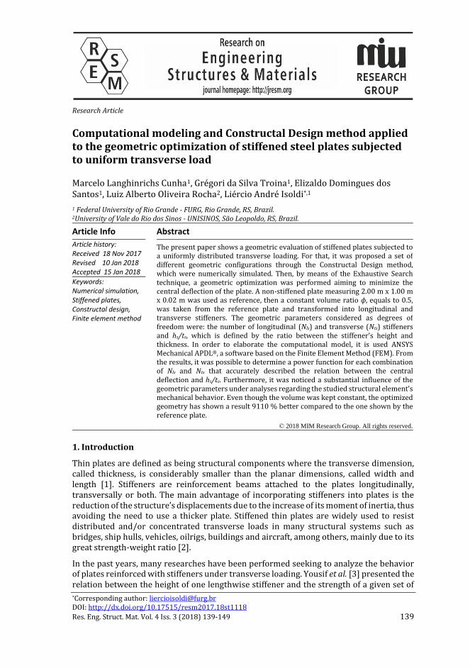
Fig. 4 Plate P(7,7) with ts = 4.75 mm and hs/ts = 42.68 using the converged mesh M3
After that, all proposed stiffened plate configurations were numerically simulated. As expected, it was noted that the redistribution of the reference plate’s material, by turning a portion of its thickness into stiffeners, improves the mechanical behavior regarding the deflection at the center since all analyzed configurations presented a lower deflection than the reference plate, where the worst analyzed geometry P(7,2) with hs/ts = 1.27 presented a displacement (Uz = 0.448 mm) 35.81% smaller than the reference plate (Uzr = 0.698 mm).
To exemplify how the variation of the hs/ts ratio influences in the central deflection of the stiffened plates, a scatter plot for the numerical results of the plates P(2,2) and P(2,7) is shown in Fig. 5. One can note that the hs/ts increase promotes a reduction in the central deflection value, being this a coherent behavior. It was also observed that it is possible to estimate a power function, which describes mathematically the relation between the variables under analysis with great accuracy. In addition to the scattered data for P(2,2) and P(2,7), in Fig. 5 it is presented a power trendline as well as the curve function and the coefficient of determination (R2) for each plate.
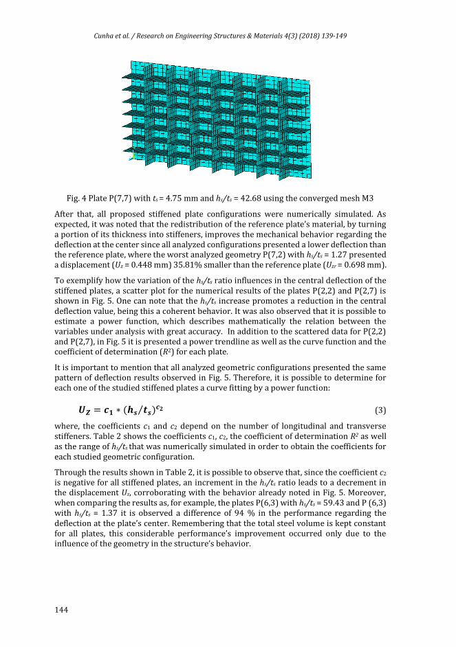
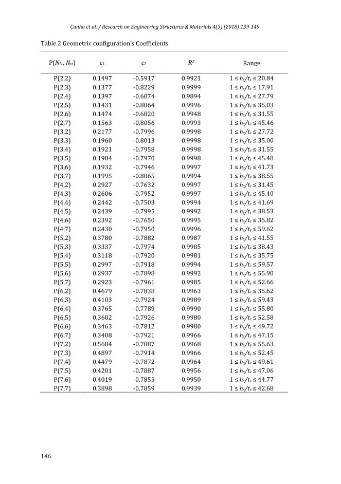
It is important to mention that all analyzed geometric configurations presented the same pattern of deflection results observed in Fig. 5. Therefore, it is possible to determine for each one of the studied stiffened plates a curve fitting by a power function:
𝑼𝒁 = 𝒄𝟏 ∗ (𝒉𝒔 𝒕𝒔⁄ )𝒄𝟐 (3)
where, the coefficients c1 and c2 depend on the number of longitudinal and transverse stiffeners. Table 2 shows the coefficients c1, c2, the coefficient of determination R2 as well as the range of hs/ts that was numerically simulated in order to obtain the coefficients for each studied geometric configuration.
Through the results shown in Table 2, it is possible to observe that, since the coefficient c2 is negative for all stiffened plates, an increment in the hs/ts ratio leads to a decrement in the displacement Uz, corroborating with the behavior already noted in Fig. 5. Moreover, when comparing the results as, for example, the plates P(6,3) with hs/ts = 59.43 and P (6,3) with hs/ts = 1.37 it is observed a difference of 94 % in the performance regarding the deflection at the plate’s center. Remembering that the total steel volume is kept constant for all plates, this considerable performance’s improvement occurred only due to the influence of the geometry in the structure’s behavior.

Cunha et al. / Research on Engineering Structures & Materials 4(3) (2018) 139-149
145
Fig. 5 Scatter plot of the relation between Uz and hs/ts of the plates P(2,2) and P(2,7) with their respectives power trendlines
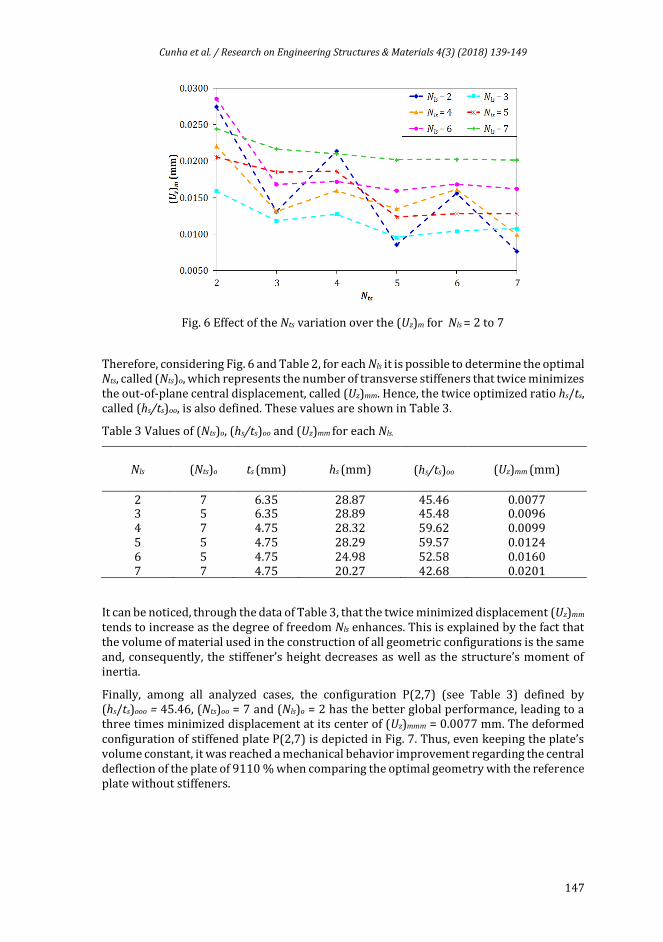
The Constructal Design method enables to perform an influence analysis of the degrees of freedom in the proposed stiffened plates’ mechanical behavior. In this context, to obtain the global minimum deflection at the center among all analyzed configurations, it was evaluated the influence of Nls, Nts and hs/ts. Based on the Eq. (3) and the coefficients presented in Table 2, for each combination of longitudinal and transverse stiffeners, it was determined the optimal hs/ts called (hs/ts)o , i.e., the hs/ts ratio that minimizes the plate’s central displacement, called (Uz)m. The graph in Fig. 6 shows the minimized displacement at the plates’ center (Uz)m for each combination of the number of transverse stiffeners Nts and the number of longitudinal stiffeners Nls.
From Fig. 6, contrary to the common sense, it is not possible to affirm that an increase in the number of stiffeners always will generate an improvement in the plate stiffness. This is because the volume of material is constant, so an increase in the number of stiffeners entails a reduction in their height and hence the cross-sectional moment of inertia becomes smaller. Another important observation about Fig. 6 is that the results have an oscillating trend, which demonstrates that plates with an odd number of transverse stiffeners (Nts) present better results when compared with those with an even number of transverse stiffeners. This can be explained by the fact that plates with an odd Nts have a stiffener at its very center, reducing its central deflection.
Cunha et al. / Research on Engineering Structures & Materials 4(3) (2018) 139-149
146
Table 2 Geometric configuration’s Coefficients
P(Nls , Nts) c1 c2 R2
Range
P(2,2) 0.1497 -0.5917 0.9921 1 ≤ hs/ts ≤ 20.84
P(2,3) 0.1377 -0.8229 0.9999 1 ≤ hs/ts ≤ 17.91
P(2,4) 0.1397 -0.6074 0.9894 1 ≤ hs/ts ≤ 27.79
P(2,5) 0.1431 -0.8064 0.9996 1 ≤ hs/ts ≤ 35.03
P(2,6) 0.1474 -0.6820 0.9948 1 ≤ hs/ts ≤ 31.55
P(2,7) 0.1563 -0.8056 0.9993 1 ≤ hs/ts ≤ 45.46
P(3,2) 0.2177 -0.7996 0.9998 1 ≤ hs/ts ≤ 27.72
P(3,3) 0.1960 -0.8013 0.9998 1 ≤ hs/ts ≤ 35.00
P(3,4) 0.1921 -0.7958 0.9998 1 ≤ hs/ts ≤ 31.55
P(3,5) 0.1904 -0.7970 0.9998 1 ≤ hs/ts ≤ 45.48
P(3,6) 0.1932 -0.7946 0.9997 1 ≤ hs/ts ≤ 41.73
P(3,7) 0.1995 -0.8065 0.9994 1 ≤ hs/ts ≤ 38.55
P(4,2) 0.2927 -0.7632 0.9997 1 ≤ hs/ts ≤ 31.45
P(4,3) 0.2606 -0.7952 0.9997 1 ≤ hs/ts ≤ 45.40
P(4,4) 0.2442 -0.7503 0.9994 1 ≤ hs/ts ≤ 41.69
P(4,5) 0.2439 -0.7995 0.9992 1 ≤ hs/ts ≤ 38.53
P(4,6) 0.2392 -0.7650 0.9995 1 ≤ hs/ts ≤ 35.82
P(4,7) 0.2430 -0.7950 0.9996 1 ≤ hs/ts ≤ 59.62
P(5,2) 0.3780 -0.7882 0.9987 1 ≤ hs/ts ≤ 41.55
P(5,3) 0.3337 -0.7974 0.9985 1 ≤ hs/ts ≤ 38.43
P(5,4) 0.3118 -0.7920 0.9981 1 ≤ hs/ts ≤ 35.75
P(5,5) 0.2997 -0.7918 0.9994 1 ≤ hs/ts ≤ 59.57
P(5,6) 0.2937 -0.7898 0.9992 1 ≤ hs/ts ≤ 55.90
P(5,7) 0.2923 -0.7961 0.9985 1 ≤ hs/ts ≤ 52.66
P(6,2) 0.4679 -0.7838 0.9963 1 ≤ hs/ts ≤ 35.62
P(6,3) 0.4103 -0.7924 0.9989 1 ≤ hs/ts ≤ 59.43
P(6,4) 0.3765 -0.7789 0.9990 1 ≤ hs/ts ≤ 55.80
P(6,5) 0.3602 -0.7926 0.9980 1 ≤ hs/ts ≤ 52.58
P(6,6) 0.3463 -0.7812 0.9980 1 ≤ hs/ts ≤ 49.72
P(6,7) 0.3408 -0.7921 0.9966 1 ≤ hs/ts ≤ 47.15
P(7,2) 0.5684 -0.7887 0.9968 1 ≤ hs/ts ≤ 55.63
P(7,3) 0.4897 -0.7914 0.9966 1 ≤ hs/ts ≤ 52.45
P(7,4) 0.4479 -0.7872 0.9964 1 ≤ hs/ts ≤ 49.61
P(7,5) 0.4201 -0.7887 0.9956 1 ≤ hs/ts ≤ 47.06
P(7,6) 0.4019 -0.7855 0.9950 1 ≤ hs/ts ≤ 44.77
P(7,7) 0.3898 -0.7859 0.9939 1 ≤ hs/ts ≤ 42.68
Cunha et al. / Research on Engineering Structures & Materials 4(3) (2018) 139-149
147
Fig. 6 Effect of the Nts variation over the (Uz)m for Nls = 2 to 7
Therefore, considering Fig. 6 and Table 2, for each Nls it is possible to determine the optimal Nts, called (Nts)o, which represents the number of transverse stiffeners that twice minimizes the out-of-plane central displacement, called (Uz)mm. Hence, the twice optimized ratio hs/ts, called (hs/ts)oo, is also defined. These values are shown in Table 3.
Table 3 Values of (Nts)o, (hs/ts)oo and (Uz)mm for each Nls.
Nls (Nts)o ts (mm) hs (mm)
(hs/ts)oo (Uz)mm (mm)
2
7 6.35 28.87 45.46 0.0077 3 5 6.35 28.89 45.48 0.0096 4 7 4.75
28.32 59.62 0.0099 5 5 4.75 28.29 59.57 0.0124 6 5 4.75 24.98 52.58 0.0160 7 7 4.75 20.27 42.68 0.0201
It can be noticed, through the data of Table 3, that the twice minimized displacement (Uz)mm
tends to increase as the degree of freedom Nls enhances. This is explained by the fact that the volume of material used in the construction of all geometric configurations is the same and, consequently, the stiffener’s height decreases as well as the structure’s moment of inertia.
Finally, among all analyzed cases, the configuration P(2,7) (see Table 3) defined by (hs/ts)ooo = 45.46, (Nts)oo = 7 and (Nls)o = 2 has the better global performance, leading to a three times minimized displacement at its center of (Uz)mmm = 0.0077 mm. The deformed configuration of stiffened plate P(2,7) is depicted in Fig. 7. Thus, even keeping the plate’s volume constant, it was reached a mechanical behavior improvement regarding the central deflection of the plate of 9110 % when comparing the optimal geometry with the reference plate without stiffeners.

Cunha et al. / Research on Engineering Structures & Materials 4(3) (2018) 139-149
148
Fig. 7 Deformed configuration of the optimal global plate P(2,7), in mm
5. Conclusion
By using the software ANSYS® to analyze the computational models of the plates derived from the application of the Constructal Design method, it was possible to perform an evaluation about the influence of different geometric parameters on the mechanical behavior of stiffened plates, which are important components widely used in the structural engineering.
It was observed that a rearrangement of material, even without changing the total material’s volume of the studied structural component, can entail an improvement in the structural stiffness. It was also shown that besides the number of transverse and longitudinal stiffeners, the ratio hs/ts has a significant influence in the plates’ stiffness.
Moreover, for each combination of the degrees of freedom Nts and Nls, it was possible to define a regression equation, which describes the relation between the central displacement and the degree of freedom hs/ts with great accuracy, presenting a coefficient of determination R2 greater than 99 %. Therefore, through these equations, it is possible to infer the displacements at the center of the plates for values of the ratio hs/ts within the simulated range and even to extrapolate these results, being this an unpublished scientific contribution of the present work.
Through the obtained results, it was observed that since all studied plates have the same volume, an increment in the number of stiffeners does not mean a reduction in the deflection at the plate’s center, emphasizing the significance of performing studies regarding the geometric optimization of structural components. In addition, it was noticed that the geometry has a great influence in the structural behavior of the plates, where, for example, the plate P(6,3) with hs/ts = 59.43 presented a displacement 94 % smaller when compared with the plate P(6,3) with hs/ts = 1.37. The optimal geometry, among all analyzed configurations, was the plate P(2,7) with the degree of freedom hs/ts = 45.46, whose deflection at the center was 9110 % better than the plate without stiffeners used as reference.
Therefore, through the application of computational modeling along with Constructal Design it is possible to make recommendations about the suitable geometry to be used as well as to draw conclusions about the structural behavior of varied plates’ geometries,
Cunha et al. / Research on Engineering Structures & Materials 4(3) (2018) 139-149
149
thereby enabling to optimize these structures regarding the minimization of the displacement at the center when subjected to uniform transverse loads.
6. Acknowledgements
The authors thank FAPERGS (Research Support Foundation of Rio Grande do Sul), CNPq (Brazilian National Council for Scientific and Technological Development) and CAPES (Brazilian Coordination for Improvement of Higher Education Personnel) for the financial support.
References
[1] Timoshenko S, Woinowsky-Krieger S. Theory of Plates and Shells, McGraw-Hill, New York, NY, USA, 1976.
[2] Shanmugan N E, Liew J Y R, Thevendran V. Thin-walled Structures – Research and Development, Elsevier, Singapore, 1998.
[3] Yousif M Z, Naief N K M, Hamada Y M. Optimum height of plate stiffener under pressure effect. The 1st Regional Conference of Eng. Sci. NUCEJ Spatial ISSUE; 11(3): 459 – 468, 2008.
[4] Virág Z. Optimum design of stiffened plates for different loads and shapes of ribs. Journal of Computational and Applied Mechanics, 2004; 5(1): 165-179.
[5] Tanaka M, Bercin A N. Static bending analysis of stiffened plates using the boundary element method. Engineering Analysis with Boundary Elements, 1998; 21: 147 -154. https://doi.org/10.1016/S0955-7997(98)00002-2
[6] Bedair O K. Influence of stiffener location on the stability of stiffened plates under compression and in-plane bending. Int. J. Mech. Sci, 1997; 39(1): 33 – 49. https://doi.org/10.1016/0020-7403(96)00017-3
[7] Silva H B S. Análise numérica da influência da excentricidade na ligação placa-viga em pavimentos usuais de edifícios. Master Thesis, Federal University of São Carlos, São Paulo, Brazil, 2010.
[8] Bejan A. Advanced Engineering Thermodynamics 2nd Ed, Willey, New York, NY, USA, 1997.
[9] Bejan A, Lorente S. Constructal theory of generation of configuration in nature and engineering. Journal of Applied Physics 100, 041301. https://doi.org/10.1063/1.2221896
[10] Bejan A. Shape and Structure, from Engineering to Nature, Cambrigde University Press, Cambridge, England.
[11] Bejan A, Lorente S. Design with Constructal Theory, John Wiley Sons, Hoboken, NJ, USA, 2008. https://doi.org/10.1002/9780470432709
[12] Zienkiewicz O C. Finite Element Method in Engineering Science 2nd Edition, McGraw-Hill, London, England, 1971.
[13] Marinho I J P. Projeto ótimo de estruturas metálicas de arquibancadas reutilizáveis via ANSYS. Master Thesis, PUC-Rio, Rio de Janeiro, Brazil, 2002.
[14] ANSYS Inc. ANSYS User's Manual: Analysis Systems, 2009.