Embed Size (px)
Citation preview
International Journal of Emerging Technologies in Engineering Research (IJETER)
Volume 5, Issue 12, December (2017) www.ijeter.everscience.org
ISSN: 2454-6410 ©EverScience Publications 24
Computational Fluid Dynamic Analysis of Boiler
Feed Pump by Varying Blade Numbers
Kanjarla Shyam Kumar
Assistant Professor, Department of MECH, WITS warangal, oorugonda, warangal, T.S, India,Pin:506342
Ashok Govindu
PG Scholar, Department of MECH, WITS warangal, oorugonda, warangal, T.S, India,Pin:506342
Abstract - Feed pumps are an essential subsystem of boilers used
in industrial process plants and called as boiler feed pump (BFP).
Normally, BFP is high pressure unit that takes suction from
condensate return system and can be of the centrifugal type pump.
In centrifugal pump, water enters axially through the impeller
eyes and exits radially. Generally, electric motor is used as prime
mover to run the feed pump. To force water into boiler, the pump
must generate sufficient pressure to overcome steam pressure
developed by boiler. In the present study, design and analysis of
boiler feed pump having a flow of 50kg/s, rotational velocity of
2000Rpm and operating at 70 deg C has been taken up. The
various pump parameters are obtained from design and pump
model is developed using modeling software solid works to
evaluate the results at given operating conditions, CFD analysis is
carried out using Solid works flow simulations module. Blade
number has great influence on the pump performance. Therefore,
CFD analyses are carried out for the pump with 6, 7 and 8 blades.
Based on performance of every pump model, the best feed pump
design is selected. A steady state CFD analysis is carried out using
the K-ε turbulence model to solve for the Navier-Stroke’s
equation.
Three different geometry of 6,7,8 no’s of impeller blade is
modelled in solid works 2016 software, Computational fluid
dynamic analysis is performed in solid works 2016 module.
Index Terms - CFD, Solid Works, boiler feed pump, centrifugal,
turbulence.
1. INTRODUCTION
Pumps have continued to grow in size, speed and energy level,
revealing new problems that are being addressed by innovative
materials and mechanical and hydraulic design approaches.
Pump and its components must have reliable performance
without any leakage. Centrifugal pumps are used in a wide
range of applications and they can handle a variety of liquids
like boiler feed water at relatively high pressures and/or
temperatures. The present work focuses on high energy, double
volute pump, it should be operating without leakage while
subjected simultaneously maximum allowable working
pressure (M.A.W.P.) and maximum operating temperature.
However, due to the high energies involved these pumps tend
to suffer more pressure pulsations than single stage pumps.
Hence for satisfactory performance it is intended to do the
various analyses like structural analysis, Seismic analysis. So
that the important part of pump shall be designed and
possibility of failure would be examined and necessary
geometric modification will be applied to the model.
The design and arrangement of boiler feed pumps has a
significant impact on overall unit availability, In determining
the optimum arrangement of feed-pumping plant, the economic
assessment needs to take account of capital costs, capitalized
running costs, repair and maintenance costs, and the likely
effects of loss of availability.
The provision of sufficient pumping capacity to meet flow
requirements under all operational circumstances. It is normal
practice to include a flow margin to accommodate additional
demand by the turbine above its design rating during transient
flow disturbances. A margin on pump generated head is also
appropriate to cover for deterioration resulting from internal
wear during periods between overhaul. In the interests of
keeping pump set sizes and powers to a reasonable minimum,
consistent with maintaining the pump best efficiency close to
the duty point operation, these margins have been optimized as
5% on flow and 3% on generated head.
Constraints should be considered
The need to ensure that failure of a single pump set does
not impair the start-up of the main unit or affect output
capability. Standby capacity equivalent to the largest duty
pump set is indicated with a rapid start-up capability,
sufficient to prevent the loss of boiler drum level and
consequent unit trip.
The need to ensure that the plant is able to operate
satisfactorily during and after a large load rejection by the
turbine-generator unit. This requires that the drives for the
duty pumps and their power supplies must be suitable for
this operating condition. Alternatively, a suitable rapid
start/standby pump set is necessary.
The need to provide adequate NPSH margins, taking into
account that the pumps are supplied from a direct contact
heater (de-aerator), which can be subject to pressure
decay following a reduction in turbine load.
International Journal of Emerging Technologies in Engineering Research (IJETER)
Volume 5, Issue 12, December (2017) www.ijeter.everscience.org
ISSN: 2454-6410 ©EverScience Publications 25
There should be at least two pump sets capable of starting
the unit. If a turbine drive is to fulfill this function, then a
steam supply independent of the main boiler (i.e., an
auxiliary boiler) is required.
If two or more pumps are required to operate in parallel,
then the pump sets should be able to accommodate run-
out duties following loss of an operating pump.
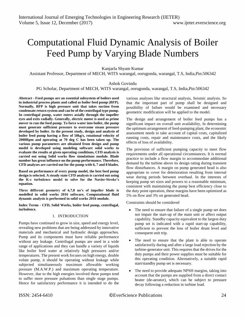
Fig: Boiler feed pump working
PUMP
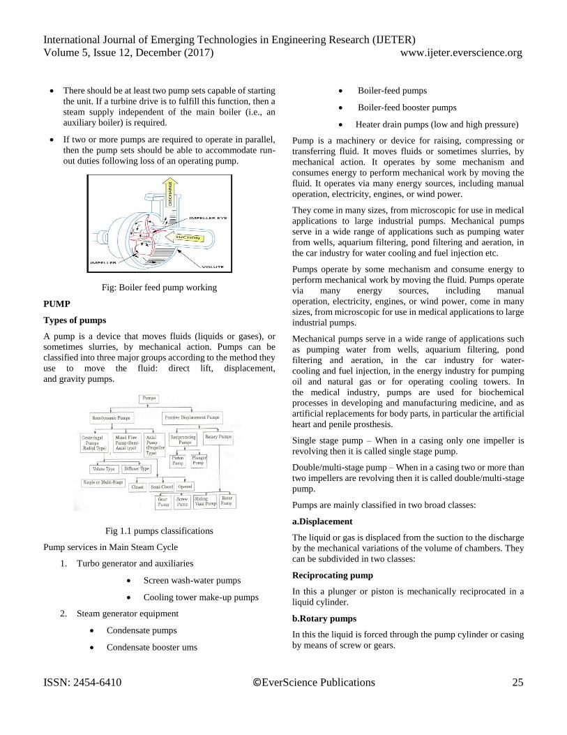
Types of pumps
A pump is a device that moves fluids (liquids or gases), or
sometimes slurries, by mechanical action. Pumps can be
classified into three major groups according to the method they
use to move the fluid: direct lift, displacement,
and gravity pumps.
Fig 1.1 pumps classifications
Pump services in Main Steam Cycle
1. Turbo generator and auxiliaries
Screen wash-water pumps
Cooling tower make-up pumps
2. Steam generator equipment
Condensate pumps
Condensate booster ums
Boiler-feed pumps
Boiler-feed booster pumps
Heater drain pumps (low and high pressure)
Pump is a machinery or device for raising, compressing or
transferring fluid. It moves fluids or sometimes slurries, by
mechanical action. It operates by some mechanism and
consumes energy to perform mechanical work by moving the
fluid. It operates via many energy sources, including manual
operation, electricity, engines, or wind power.
They come in many sizes, from microscopic for use in medical
applications to large industrial pumps. Mechanical pumps
serve in a wide range of applications such as pumping water
from wells, aquarium filtering, pond filtering and aeration, in
the car industry for water cooling and fuel injection etc.
Pumps operate by some mechanism and consume energy to
perform mechanical work by moving the fluid. Pumps operate
via many energy sources, including manual
operation, electricity, engines, or wind power, come in many
sizes, from microscopic for use in medical applications to large
industrial pumps.
Mechanical pumps serve in a wide range of applications such
as pumping water from wells, aquarium filtering, pond
filtering and aeration, in the car industry for water-
cooling and fuel injection, in the energy industry for pumping
oil and natural gas or for operating cooling towers. In
the medical industry, pumps are used for biochemical
processes in developing and manufacturing medicine, and as
artificial replacements for body parts, in particular the artificial
heart and penile prosthesis.
Single stage pump – When in a casing only one impeller is
revolving then it is called single stage pump.
Double/multi-stage pump – When in a casing two or more than
two impellers are revolving then it is called double/multi-stage
pump.
Pumps are mainly classified in two broad classes:
a.Displacement
The liquid or gas is displaced from the suction to the discharge
by the mechanical variations of the volume of chambers. They
can be subdivided in two classes:
Reciprocating pump
In this a plunger or piston is mechanically reciprocated in a
liquid cylinder.
b.Rotary pumps
In this the liquid is forced through the pump cylinder or casing
by means of screw or gears.
International Journal of Emerging Technologies in Engineering Research (IJETER)
Volume 5, Issue 12, December (2017) www.ijeter.everscience.org
ISSN: 2454-6410 ©EverScience Publications 26
Centrifugal
Flow through the pump is induced by the centrifugal force
imparted to the liquid by the rotation of an impeller or impellers
Pump Selection
From the information supplied in the data sheet, a pump can
normally be selected from the pump manufacturer’s sales book.
These are normally divided into sec- tions, each representing a
particular construction. Performance maps show the range of
capacity and head available, while individual performance
curves show efficiency and NPSHR. If the pump requirements
fall within the performances shown in the sales book, the
process of selection is relatively simple. When the re- quired
pumping conditions, however, are outside the existing range of
perfor- mance, selection is no longer simple and becomes the
responsibility of the pump designer.
Definition of Pump Specific Speed and Suction Specific
Speed
Pump specific speed (Ns) as it is applied to centrifugal pumps
is defined in U.S. unitsas:
Specific speed is always calculated at the best efficiency point
(BEP) with maximum impeller diameter and single stage only.
As specific speed can be calculated in any consistent units, it is
useful to convert the calculated number to some other
sys- tem of units. See Table 2-
1. The suction specific speed (Nss) is calculated by the same f
ormula as pump specific speed (Ns) but uses NPSHR values i
n feet in place of head (H) in feet. To calculate pump specific
speed (Ns) use full capacity (GPM) for either single- or double-
suction pumps. To calculate suction specific
speed (Nss) use one half of capacity (GPM) for double-
suction pumps.
Table Specific Speed Conversion
It is well known that specific speed is a reference number that
describes the hy- draulic features of a pump, whether radial,
semi-axial (Francis type), or propeller type.
BOILER FEED PUMP
Boiler feed pumps are also referred to as feed pumps
(see Reactor pump) and designed as multistage radial flow
pumps. (Also see Multistage pump.)
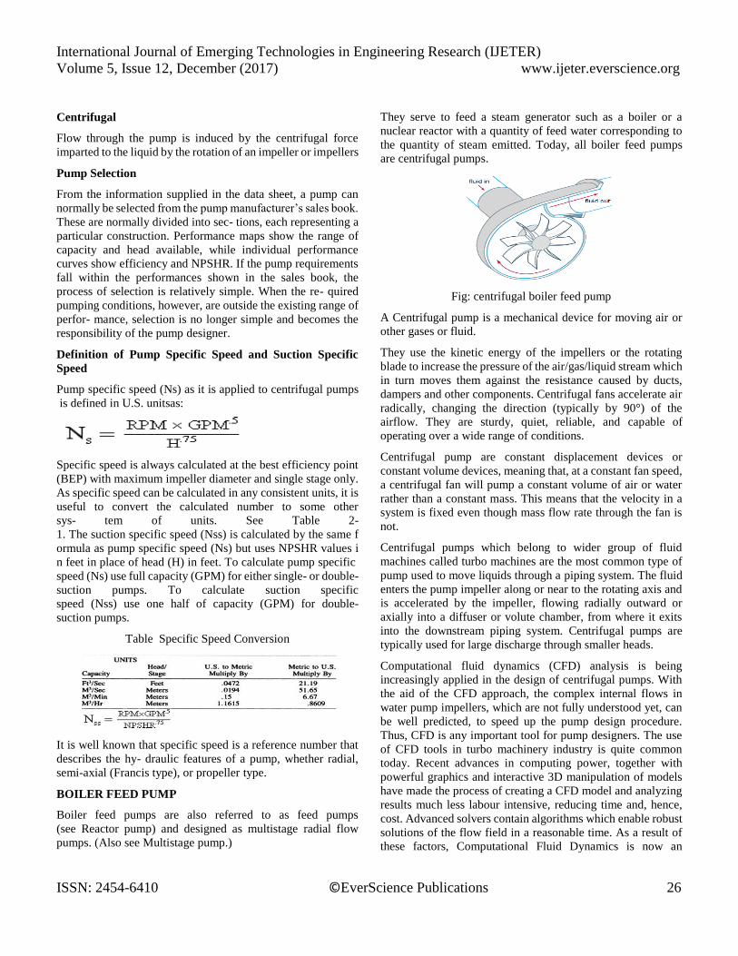
They serve to feed a steam generator such as a boiler or a
nuclear reactor with a quantity of feed water corresponding to
the quantity of steam emitted. Today, all boiler feed pumps
are centrifugal pumps.
Fig: centrifugal boiler feed pump
A Centrifugal pump is a mechanical device for moving air or
other gases or fluid.
They use the kinetic energy of the impellers or the rotating
blade to increase the pressure of the air/gas/liquid stream which
in turn moves them against the resistance caused by ducts,
dampers and other components. Centrifugal fans accelerate air
radically, changing the direction (typically by 90°) of the
airflow. They are sturdy, quiet, reliable, and capable of
operating over a wide range of conditions.
Centrifugal pump are constant displacement devices or
constant volume devices, meaning that, at a constant fan speed,
a centrifugal fan will pump a constant volume of air or water
rather than a constant mass. This means that the velocity in a
system is fixed even though mass flow rate through the fan is
not.
Centrifugal pumps which belong to wider group of fluid
machines called turbo machines are the most common type of
pump used to move liquids through a piping system. The fluid
enters the pump impeller along or near to the rotating axis and
is accelerated by the impeller, flowing radially outward or
axially into a diffuser or volute chamber, from where it exits
into the downstream piping system. Centrifugal pumps are
typically used for large discharge through smaller heads.
Computational fluid dynamics (CFD) analysis is being
increasingly applied in the design of centrifugal pumps. With
the aid of the CFD approach, the complex internal flows in
water pump impellers, which are not fully understood yet, can
be well predicted, to speed up the pump design procedure.
Thus, CFD is any important tool for pump designers. The use
of CFD tools in turbo machinery industry is quite common
today. Recent advances in computing power, together with
powerful graphics and interactive 3D manipulation of models
have made the process of creating a CFD model and analyzing
results much less labour intensive, reducing time and, hence,
cost. Advanced solvers contain algorithms which enable robust
solutions of the flow field in a reasonable time. As a result of
these factors, Computational Fluid Dynamics is now an
International Journal of Emerging Technologies in Engineering Research (IJETER)
Volume 5, Issue 12, December (2017) www.ijeter.everscience.org
ISSN: 2454-6410 ©EverScience Publications 27
established industrial design tool, helping to reduce design time
scales and improve processes throughout the engineering
world.
Purpose of Boiler feed pump:
BFP supply feed water for boiler drum in a power plant. In our
case BFP supply feed water mainlyfor HP and IP drum. Feed
water also required for:
HP Bypass Spray water
HP attemperator spray
HRH attemperator spray
Gland Steam/ Aux steam de-super heating.
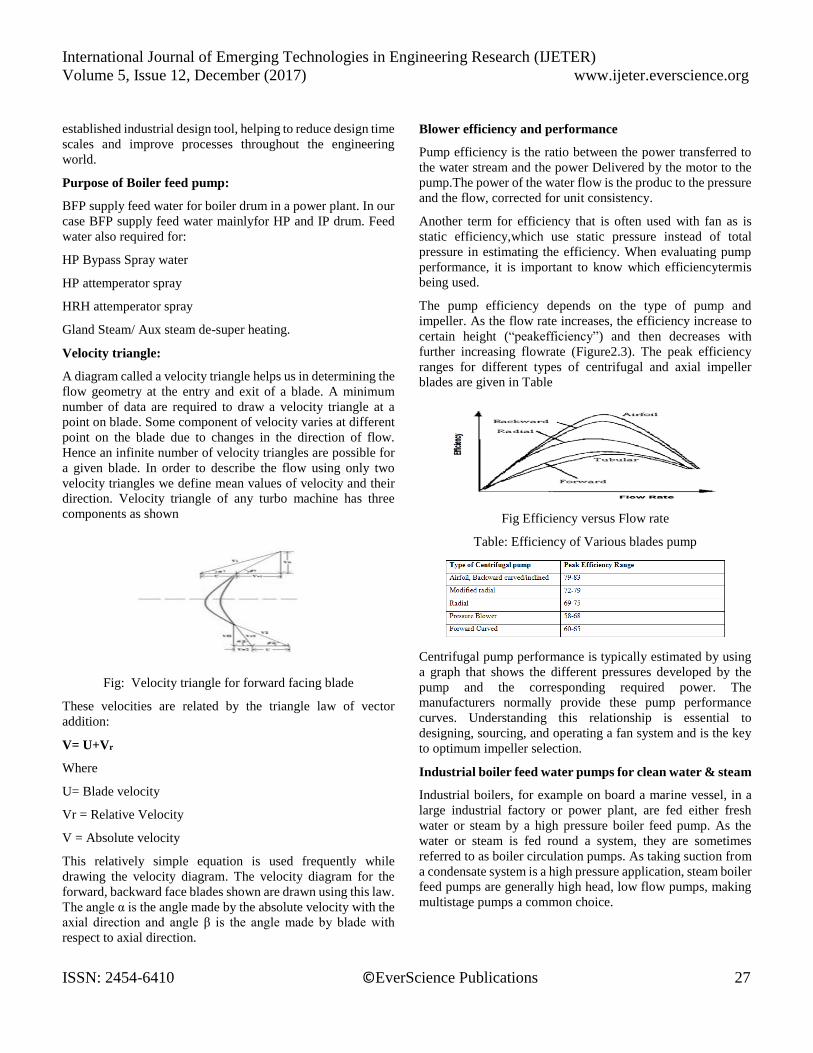
Velocity triangle:
A diagram called a velocity triangle helps us in determining the
flow geometry at the entry and exit of a blade. A minimum
number of data are required to draw a velocity triangle at a
point on blade. Some component of velocity varies at different
point on the blade due to changes in the direction of flow.
Hence an infinite number of velocity triangles are possible for
a given blade. In order to describe the flow using only two
velocity triangles we define mean values of velocity and their
direction. Velocity triangle of any turbo machine has three
components as shown
Fig: Velocity triangle for forward facing blade
These velocities are related by the triangle law of vector
addition:
V= U+Vr
Where
U= Blade velocity
Vr = Relative Velocity
V = Absolute velocity
This relatively simple equation is used frequently while
drawing the velocity diagram. The velocity diagram for the
forward, backward face blades shown are drawn using this law.
The angle α is the angle made by the absolute velocity with the
axial direction and angle β is the angle made by blade with
respect to axial direction.
Blower efficiency and performance
Pump efficiency is the ratio between the power transferred to
the water stream and the power Delivered by the motor to the
pump.The power of the water flow is the produc to the pressure
and the flow, corrected for unit consistency.
Another term for efficiency that is often used with fan as is
static efficiency,which use static pressure instead of total
pressure in estimating the efficiency. When evaluating pump
performance, it is important to know which efficiencytermis
being used.
The pump efficiency depends on the type of pump and
impeller. As the flow rate increases, the efficiency increase to
certain height (“peakefficiency”) and then decreases with
further increasing flowrate (Figure2.3). The peak efficiency
ranges for different types of centrifugal and axial impeller
blades are given in Table
Fig Efficiency versus Flow rate
Table: Efficiency of Various blades pump
Centrifugal pump performance is typically estimated by using
a graph that shows the different pressures developed by the
pump and the corresponding required power. The
manufacturers normally provide these pump performance
curves. Understanding this relationship is essential to
designing, sourcing, and operating a fan system and is the key
to optimum impeller selection.
Industrial boiler feed water pumps for clean water & steam
Industrial boilers, for example on board a marine vessel, in a
large industrial factory or power plant, are fed either fresh
water or steam by a high pressure boiler feed pump. As the
water or steam is fed round a system, they are sometimes
referred to as boiler circulation pumps. As taking suction from
a condensate system is a high pressure application, steam boiler
feed pumps are generally high head, low flow pumps, making
multistage pumps a common choice.
International Journal of Emerging Technologies in Engineering Research (IJETER)
Volume 5, Issue 12, December (2017) www.ijeter.everscience.org
ISSN: 2454-6410 ©EverScience Publications 28
2. DESIGN
There is no rigorous procedure to be followed in designing a
pump. Lot of approaches have been developed and, although
each has a slightly different method of calculation, the broad
underlying principles of all are similar. The velocity limitations
and proportions are also there to which it requires to adhere;
but these may be exceeded in certain instances to meet
competition with regard to cost or performance. The usual
design is based upon a certain desired head and capacity at
which the pump is operated most of time [4]. In design of
centrifugal pump, the parts to be designed are: shaft, impeller,
vane, casing, and selection of bearing. To design these parts
different methodologies can be obtained through literature
survey. From the given conditions, the specific speed is
obtained [5].
According to required head, the flow rate and from specific
speed, pump of double volute, double suction and single stage
type is selected. The minimum shaft diameter can be obtained
by using maximum shear stress theory. Impeller and vane are
designed according to methodology provided by Church [6].
To design the vane empirical relations are used. API standard
[7] is used to design the volute and for bearing selection. There
are different methods for volute design, but “throat area from
graph of ratio of throat velocity to impeller peripheral speed vs.
specific speed” method is used to design a volute. The
conversion of KE to PE is very important in pump and that can
be achieved with the fine shape of volute. According to
selection criterions stated in API standard [7], selection of
bearing has been done.
Specifications of feed pump are cited in table I,
Table I. Specifications of Feed Pump
3. DESCRIPTION OF THE EQUIPMENT
BOILER FEED PUMP 4B Boiler Feed Pump (BFP) is used to
pump the feed water (chemically treated water) in to the boiler.
The FK6D30 type BFP consists of FAiB56 Booster Pump (BP)
directly driven from one end of the shaft of an electric motor.
BFP is driven from the opposite end of Motor shaft through a
spacer type flexible coupling. The BP is a single stage,
horizontal, axial split casing type, having the suction and
discharge branches on the casing bottom half, thus allowing the
pump internals to be removed without disturbing the suction
and discharge pipe work or the alignment between the pump
and the driving motor.
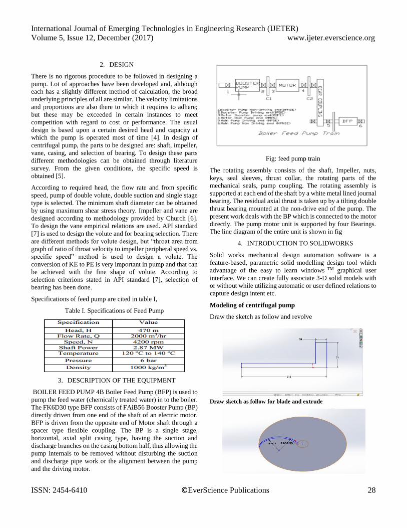
Fig: feed pump train
The rotating assembly consists of the shaft, Impeller, nuts,
keys, seal sleeves, thrust collar, the rotating parts of the
mechanical seals, pump coupling. The rotating assembly is
supported at each end of the shaft by a white metal lined journal
bearing. The residual axial thrust is taken up by a tilting double
thrust bearing mounted at the non-drive end of the pump. The
present work deals with the BP which is connected to the motor
directly. The pump motor unit is supported by four Bearings.
The line diagram of the entire unit is shown in fig
4. INTRODUCTION TO SOLIDWORKS
Solid works mechanical design automation software is a
feature-based, parametric solid modelling design tool which
advantage of the easy to learn windows TM graphical user
interface. We can create fully associate 3-D solid models with
or without while utilizing automatic or user defined relations to
capture design intent etc.
Modeling of centrifugal pump
Draw the sketch as follow and revolve
Draw sketch as follow for blade and extrude
International Journal of Emerging Technologies in Engineering Research (IJETER)
Volume 5, Issue 12, December (2017) www.ijeter.everscience.org
ISSN: 2454-6410 ©EverScience Publications 29
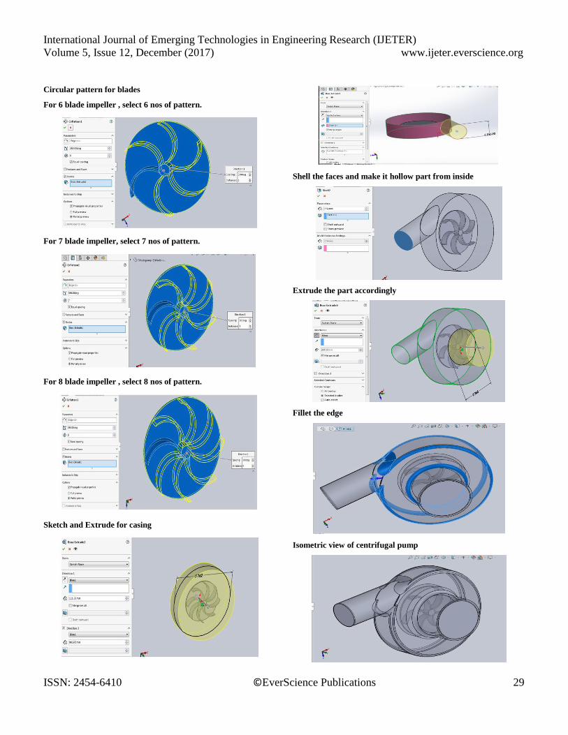
Circular pattern for blades
For 6 blade impeller , select 6 nos of pattern.
For 7 blade impeller, select 7 nos of pattern.
For 8 blade impeller , select 8 nos of pattern.
Sketch and Extrude for casing
Shell the faces and make it hollow part from inside
Extrude the part accordingly
Fillet the edge
Isometric view of centrifugal pump
International Journal of Emerging Technologies in Engineering Research (IJETER)
Volume 5, Issue 12, December (2017) www.ijeter.everscience.org
ISSN: 2454-6410 ©EverScience Publications 30
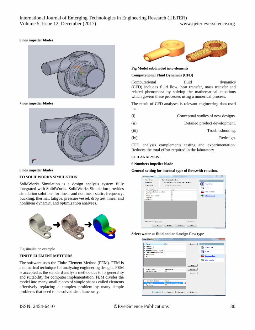
6 nos impeller blades
7 nos impeller blades
8 nos impeller blades
TO SOLIDWORKS SIMULATION
SolidWorks Simulation is a design analysis system fully
integrated with SolidWorks. SolidWorks Simulation provides
simulation solutions for linear and nonlinear static, frequency,
buckling, thermal, fatigue, pressure vessel, drop test, linear and
nonlinear dynamic, and optimization analyses.
Fig simulation example
FINITE ELEMENT METHODS
The software uses the Finite Element Method (FEM). FEM is
a numerical technique for analyzing engineering designs. FEM
is accepted as the standard analysis method due to its generality
and suitability for computer implementation. FEM divides the
model into many small pieces of simple shapes called elements
effectively replacing a complex problem by many simple
problems that need to be solved simultaneously.
Fig Model subdivided into elements
Computational Fluid Dynamics (CFD)
Computational fluid dynamics
(CFD) includes fluid flow, heat transfer, mass transfer and
related phenomena by solving the mathematical equations
which govern these processes using a numerical process.
The result of CFD analyses is relevant engineering data used
in:
(i) Conceptual studies of new designs.
(ii) Detailed product development.
(iii) Troubleshooting.
(iv) Redesign.
CFD analysis complements testing and experimentation.
Reduces the total effort required in the laboratory.
CFD ANALYSIS
6 Numbers impeller blade
General setting for internal type of flow,with rotation.
Select water as fluid and and assign flow type
International Journal of Emerging Technologies in Engineering Research (IJETER)
Volume 5, Issue 12, December (2017) www.ijeter.everscience.org
ISSN: 2454-6410 ©EverScience Publications 31
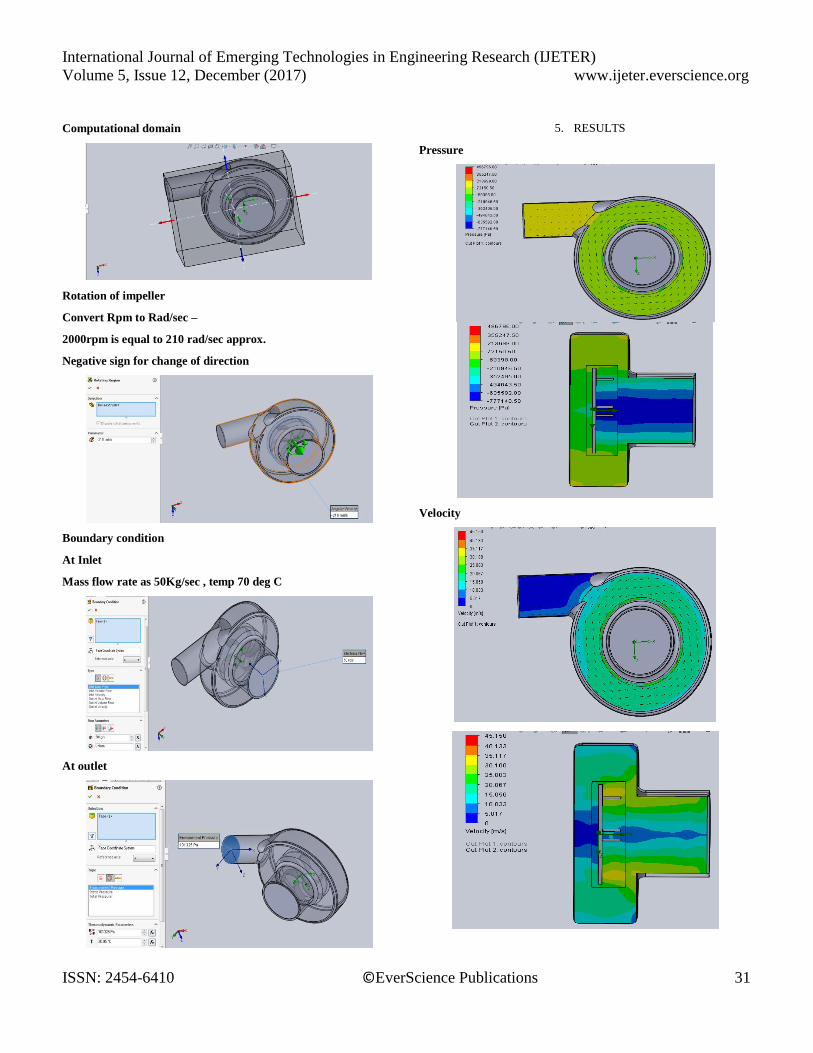
Computational domain
Rotation of impeller
Convert Rpm to Rad/sec –
2000rpm is equal to 210 rad/sec approx.
Negative sign for change of direction
Boundary condition
At Inlet
Mass flow rate as 50Kg/sec , temp 70 deg C
At outlet
5. RESULTS
Pressure
Velocity
International Journal of Emerging Technologies in Engineering Research (IJETER)
Volume 5, Issue 12, December (2017) www.ijeter.everscience.org
ISSN: 2454-6410 ©EverScience Publications 32
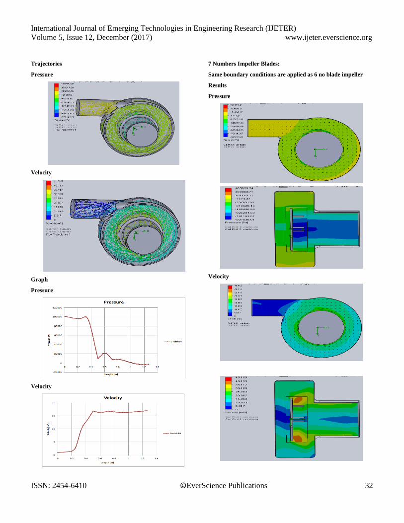
Trajectories
Pressure
Velocity
Graph
Pressure
Velocity
7 Numbers Impeller Blades:
Same boundary conditions are applied as 6 no blade impeller
Results
Pressure
Velocity
International Journal of Emerging Technologies in Engineering Research (IJETER)
Volume 5, Issue 12, December (2017) www.ijeter.everscience.org
ISSN: 2454-6410 ©EverScience Publications 33
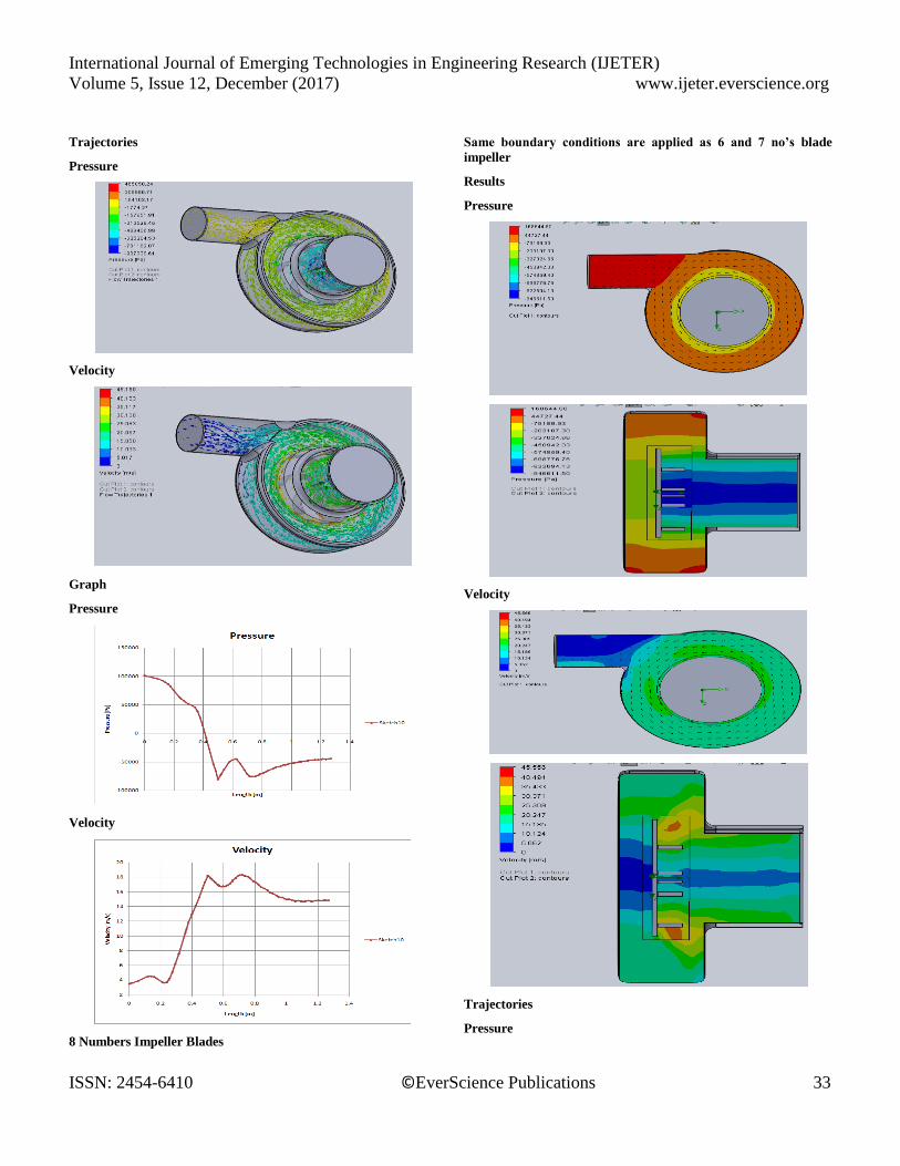
Trajectories
Pressure
Velocity
Graph
Pressure
Velocity
8 Numbers Impeller Blades
Same boundary conditions are applied as 6 and 7 no’s blade
impeller
Results
Pressure
Velocity
Trajectories
Pressure
International Journal of Emerging Technologies in Engineering Research (IJETER)
Volume 5, Issue 12, December (2017) www.ijeter.everscience.org
ISSN: 2454-6410 ©EverScience Publications 34
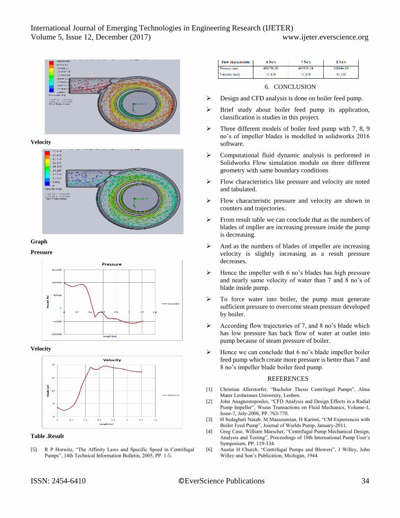
Velocity
Graph
Pressure
Velocity
Table .Result
6. CONCLUSION
Design and CFD analysis is done on boiler feed pump.
Brief study about boiler feed pump its application,
classification is studies in this project.
Three different models of boiler feed pump with 7, 8, 9
no’s of impeller blades is modelled in solidworks 2016
software.
Computational fluid dynamic analysis is performed in
Solidworks Flow simulation module on three different
geometry with same boundary conditions
Flow characteristics like pressure and velocity are noted
and tabulated.
Flow characteristic pressure and velocity are shown in
counters and trajectories.
From result table we can conclude that as the numbers of
blades of impller are increasing pressure inside the pump
is decreasing.
And as the numbers of blades of impeller are increasing
velocity is slightly increasing as a result pressure
decreases.
Hence the impeller with 6 no’s blades has high pressure
and nearly same velocity of water than 7 and 8 no’s of
blade inside pump.
To force water into boiler, the pump must generate
sufficient pressure to overcome steam pressure developed
by boiler.
According flow trajectories of 7, and 8 no’s blade which
has low pressure has back flow of water at outlet into
pump because of steam pressure of boiler.
Hence we can conclude that 6 no’s blade impeller boiler
feed pump which create more pressure is better than 7 and
8 no’s impeller blade boiler feed pump.
REFERENCES
[1] Christian Allerstorfer, “Bachelor Thesis Centrifugal Pumps”, Alma
Mater Leobeinses University, Leoben.
[2] John Anagnostopoulos, “CFD Analysis and Design Effects in a Radial Pump Impeller”, Wseas Transactions on Fluid Mechanics, Volume-1,
Issue-7, July-2006, PP. 763-770.
[3] H Sedaghati Nasab, M Massoumian, H Karimi, “CM Experiences with Boiler Feed Pump”, Journal of Worlds Pump, January-2011.
[4] Greg Case, William Marscher, “Centrifugal Pump Mechanical Design,
Analysis and Testing”, Proceedings of 18th International Pump User’s Symposium, PP. 119-134.
[5] R P Horwitz, “The Affinity Laws and Specific Speed in Centrifugal
Pumps”, 14th Technical Information Bulletin, 2005, PP. 1-5.
[6] Austin H Church, “Centrifugal Pumps and Blowers”, J Willey, John
Willey and Son’s Publication, Michigan, 1944.
International Journal of Emerging Technologies in Engineering Research (IJETER)
Volume 5, Issue 12, December (2017) www.ijeter.everscience.org
ISSN: 2454-6410 ©EverScience Publications 35
[7] “Centrifugal Pumps for Petroleum, Petrochemical and Natural Gas
Industries”, ANSI/API Standard-610, 7th Edition, API Publishing Services, Washington, September-2010.
[8] C R Mischke, “Design of Shaft”, Shaft and its Design Based on Strength,
Module-8, Lesson-1, Version-2, 1989. [9] Khin Cho Thin, Mya Mya khaing and Khin Maung Aye, “Design and
Performance Analysis of Centrifugal Pump”, World academy of
Science, Engineering and Technology, 2008, PP. 422-429. [10] Igor Karassik, J Messina, P cooper, C C Heald, “Pump Handbook”, 3rd
Edition, McGraw Hill Publication, New York, 2001.
[11] S R Shah, S V Jain, V J Lakhera, “CFD for Centrifugal Pumps: A Review of the State-of-the-Art”, Chemical, Civil and Mechanical
Engineering Tracks of 3rd Nirma University International Conference,
Ahmedabad , india, 2012, PP. 715-720. [12] M Mohammed Mohaideen, “Optimization of Backward Curved
Aerofoil Radial Fan Impeller using Finite Element Modelling”, 2012,
PP. 1592-1598.
[13] S R Shah, S V Jain, V J Lakhera, “CFD Based Flow Analysis of
Centrifugal Pump”, 4th International Conference on Fluid Mechanics and Fluid Power, Chennai, December-2010, PP. 435-441.
[14] S Chakraborty, K M Pandey, “Numerical Studies on Effect of Blade
Number Variations on Performance of Centrifugal Pumps at 4000 rpm”, International Journal of Engineering and Technology, Volume-3,
Number-4, August-2011, PP. 1-7.
Author
Kanjarla Shyam Kumar: Working as Assistant
Professor in warangal institute of technology &
science, warangal(R) in mechanical department.having many industrial relationships
with different oragansitations in and outside the state
of Telangana. Having industrial experience with thermal power plant. Now working as committee
member for R&D department for various research
projects of Post graduate & bachelor degree students.


![005014916 00171...KIRKPATRICK Francis [247] 7 May Probate of the Will of Francis Kirkpatrick late of 96 Henry Street Belfast Boiler Maker who died 5 April 1909 granted at Belfast to](https://img.pdfslide.us/doc/110x75/610d3bb60e9dc817b6071c4b/005014916-kirkpatrick-francis-247-7-may-probate-of-the-will-of-francis-kirkpatrick.jpg)