Embed Size (px)
Citation preview
Computational Design and Fabrication of Soft Pneumatic Objectswith Desired Deformations
LI-KE MA∗, Tsinghua University and Microsoft Research AsiaYIZHONG ZHANG∗, Microsoft Research AsiaYANG LIU, Microsoft Research AsiaKUN ZHOU, Zhejiang UniversityXIN TONG, Microsoft Research Asia
Rest shape
Target 1 Target 2 Material optimization
Rigid region Constructed chambers
Constructed frame structure Fabricated pneumatic soft object
(a) (b) (c) (d)
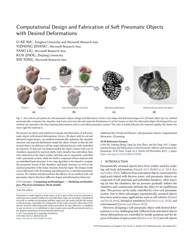
Fig. 1. Our end-to-end system for soft pneumatic objects design and fabrication. Given a rest shape and deformed shapes of a 3D heart object (a), our methodautomatically computes the chamber and frame structure (b) and material distribution (c) of the frames so that the fabricated object (d) designed by ourmethod can reproduce the heart beating deformations with a controlled pneumatic system. The color in (c&d) indicates the material rigidity, the darker themore rigid the material is.
We present an end-to-end solution for design and fabrication of soft pneu-matic objects with desired deformations. Given a 3D object with its rest anddeformed target shapes, our method automatically optimizes the chamberstructure and material distribution inside the object volume so that the fab-ricated object can deform to all the target deformed poses with controlledair injection. To this end, our method models the object volume with a set ofchambers separated by material shells. Each chamber has individual chan-nels connected to the object surface and thus can be separately controlledwith a pneumatic system, while the shell is comprised of base material withan embedded frame structure. A two-step algorithm is developed to computethe geometric layout of the chambers and frame structure as well as thematerial properties of the frame structure from the input. The design resultscan be fabricated with 3D printing and deformed by a controlled pneumaticsystem. We validate and demonstrate the efficacy of our method with softpneumatic objects that have different shapes and deformation behaviors.
CCS Concepts: • Computing methodologies → Modeling methodolo-gies; Physical simulation;Mesh models;
∗Joint first authors
Permission to make digital or hard copies of all or part of this work for personal orclassroom use is granted without fee provided that copies are not made or distributedfor profit or commercial advantage and that copies bear this notice and the full citationon the first page. Copyrights for components of this work owned by others than ACMmust be honored. Abstracting with credit is permitted. To copy otherwise, or republish,to post on servers or to redistribute to lists, requires prior specific permission and/or afee. Request permissions from [email protected].© 2017 Association for Computing Machinery.0730-0301/2017/11-ART239 $15.00https://doi.org/10.1145/3130800.3130850
Additional Key Words and Phrases: soft pneumatic objects, computationalfabrication, 3D printing
ACM Reference Format:Li-Ke Ma, Yizhong Zhang, Yang Liu, Kun Zhou, and Xin Tong. 2017. Compu-tational Design and Fabrication of Soft Pneumatic Objects with Desired De-formations. ACM Trans. Graph. 36, 6, Article 239 (November 2017), 12 pages.https://doi.org/10.1145/3130800.3130850
1 INTRODUCTIONPneumatically actuated objects have been widely used for realiz-ing soft body deformations [Majidi 2013; Rieffel et al. 2014; Rusand Tolley 2015]. Different from articulated objects constructed byrigid parts linked with discrete joints, soft pneumatic objects arecomposed of soft materials and embedded chambers. After inject-ing air into the chambers, the air pressure gradually inflates thechambers and continuously deforms the object to its equilibriumstate. This process can be easily controlled by a low-cost pneumaticsystem. Due to these advantages, pneumatically actuated objectshave been used in many applications, such as soft robotics [Deimeland Brock 2016], biological simulation [Marchese et al. 2014], andentertainment [Jamele and Ellison 2013].However, designing a soft pneumatic object with desired defor-
mations is a very challenging task. Different from articulated objectswhose deformations are controlled by handle positions and the de-grees of freedom of sparse joints [Bächer et al. 2012] and soft objects
ACM Transactions on Graphics, Vol. 36, No. 6, Article 239. Publication date: November 2017.

239:2 • Li-Ke Ma, Yizhong Zhang, Yang Liu, Kun Zhou, and Xin Tong
driven by external forces [Skouras et al. 2013], the deformation ofa pneumatically actuated object is affected by multiple factors: thegeometry (i.e., shape and layout) of the empty chambers, the ma-terial properties inside the object volume, and the air pressure ineach pneumatic chamber. All these factors are coupled together ina highly non-linear physical process to determine the deformationof the object surface, which makes the design of soft pneumatic ob-jects with desired deformations extremely difficult. Existing designefforts for soft pneumatic objects either focus on simple-shapedpneumatic actuators with 1D elasticity or bending [Elsayed et al.2014; Yap et al. 2016], or follow trial-and-error to manually designsoft pneumatic objects with specific deformations [Marchese et al.2014]. To the best of our knowledge, there is no end-to-end solutionfor designing soft pneumatic objects with desired deformations.In this paper, we take one step forward toward an end-to-end
method for designing and fabricating soft pneumatic objects withdesired deformations. Given a 3D object shape and a set of deformedtarget shapes that the object needs to achieve at its equilibriumstate (Fig. 1(a)), our method automatically computes the pneumaticchamber structure and the material properties inside the objectvolume structure, as well as the air pressure of each individualpneumatic chamber to generate a 3D printable object so that thesimulated deformations of the designed object volume can achieveall the target shapes (Fig. 1(b&c)). After fabrication, the object withdesigned internal structure can deform to each target pose after theair pressure in each chamber achieves the optimized value (Fig. 1(d)).The key observation of our solution is that in a soft pneumatic
object volume, the chamber and the surrounding material play dif-ferent roles in object deformation. The inflated chamber drivenby air pressure produces large and isotropic deformations, whilethe surrounding soft material provides fine scale and anisotropicconstraints for the chamber deformation. Based on this observa-tion, we model the object volume with a set of chambers separatedwith material shells (Fig. 1(b)). Each chamber has an individual airchannel to the model surface that is connected to the pneumaticsystem using an air tube, thus it can be separately controlled to ap-proximate the large scale volumetric deformation. The surroundingshells driven by the inflated chambers are used to simulate fine-scaleanisotropic deformations. Inspired by the fiber structure used formany soft objects [Connolly et al. 2017; Polygerinos et al. 2015b], wefurther simplify the material distribution in the shells by modelingthe shell with a homogeneous soft base material with embedded 2Dframes. Each frame segment is homogeneous while different framesegments are made of various materials and thus have differentphysical properties.
Our simplified internal structure model greatly reduces the num-ber of unknowns and makes the design optimization tractable. Tothis end, we develop an efficient algorithm to optimize the geometryand physical properties of the model in two separate steps. In thefirst step, we assume that the object volume is filled with the homo-geneous base material and compute the volumetric deformationsfrom the target poses with a physically based simulation. We thenidentify the volumetric regions sharing similar large deformationsand replace each of them with separate chambers. After that, weembed the frames around each chamber with their directions fol-lowing the principal Green strain directions as much as possible. In
the second step, we optimize the material properties of each framesegment in the shell as well as the air pressure in each chamber sothat the simulated deformation of the designed object can achievethe desired deformations.
We implemented our system and fabricated a set of soft pneumaticobjects that have different 3D shapes and deformation behaviors.Controlled by a pneumatic system, the 3D-printed objects success-fully reproduce all target poses. We also compare our method withother alternative solutions to validate the efficacy of our method.
2 RELATED WORK
2.1 Active deformable modelActive deformable models, also called soft robots, can mimic thephysical behavior of various objects and perform different taskssuch as grasping or moving on unknown surfaces. Compared torigid robotics, they are more suitable for medical, human interaction,and wearable applications as they reduce the potential harm to thehuman body and thus have gained much attention in both academiaand industry [Rus and Tolley 2015].
Design of active deformable models. Many active deformable mod-els have been proposed for different tasks, and most of them usedfluid control (i.e. pneumatic or hydraulic actuation) for achievingquick response and rapid motion due to the great output powerof fluid control systems. Marchese et al. [2014] construct a self-contained soft robotic fish with some tiny and compact pneumaticdevices. Polygerinos et al. [2015a] make a hydraulic actuated softrobotic glove to augment hand rehabilitation for individuals withfunctional grasp pathologies. Deimel et al. [2016] build a pneumati-cally actuated robotic hand that can perform grasping. This robot isfabricated using silicone rubber and embedded with inelastic fabricso that when the rubber actuator is inflated, it can bend to the direc-tion where the embedded inelastic fabric is. Moseley et al. [2016]design the chamber layout manually for soft pneumatic actuatorsand validate the result by the finite element method. However, theshape of actuators after injecting air can have many bumps, and itis not suitable for matching the desired target shapes.
Besides fluid control, there are also soft robots actuated by shapememory alloys and chemical reactions. Inspired by the motion ofan octopus, Laschi et al. [2012] build robotic octopus arms thatcan be bent and twisted by actuating a shape memory alloy, whichshrinks under electric heating. However, the speed of arm motionis relatively slow because the temperature of a shape memory alloycannot be suddenly changed. Wehner et al. [2016] use the activationof two chemical fluids to actuate the motion of fully-soft robots, butthe structure of the robot is difficult to fabricate due to its complexity.
Since most existing active deformable models are built for specifictasks, they are typically manually-designed with the aid of commer-cial CAD systems. However, current CAD systems cannot be spec-ified to deal with deformable models, resulting in difficulty in softrobot design. People have started to explore alternative methods forautomated design. Hiller et al. [2012] use an evolutionary algorithmfor design optimization, but their voxel representation of shapescannot preserve the rest shape of the model well. Rieffel et al. [2014]also use an evolutionary method but face manufacturing difficultiesbecause they do not take the fabrication process into consideration.
ACM Transactions on Graphics, Vol. 36, No. 6, Article 239. Publication date: November 2017.

Computational Design and Fabrication of Soft Pneumatic Objects with Desired Deformations • 239:3
Fabrication of active deformable models. Traditionally, active de-formable models are fabricated using 3D molding of silicone rubber.Recently, 3D printing has also been used in this area due to its con-venience and economy [Trimmer et al. 2015] since rigid componentscan be printed easily [Megaro et al. 2015] and flexible materials arealso available for some types of 3D printers. Bartlett et al. [2015]print the shell of a jumping robot with smoothly decreasing stiffnessfrom interior to exterior using a PolyJet 3D printer. Peele et al. [2015]print a pneumatic artificial muscle using an SLA 3D printer. Yap etal. [2016] print high force pneumatic actuators with an FDM 3Dprinter to take advantage of the large stretchability of 3D printing fil-aments. Although these active deformable models take 3D printingas the fabrication method, the models are still designed manually.
2.2 Computational fabricationAs dicussed in Sec. 2.1, the conflict between design and fabricationis the main obstacle in making active deformable models. Recentlywith the development of fast prototyping techniques, especially 3Dprinting, integrating design with fabrication has become easy, withso-called computational fabrication. Models with various physicalproperties can be designed and printed via computational fabri-cation: user-defined BRDF materials [Lan et al. 2013], subsurfacescattering [Dong et al. 2010], haptic feedback [Torres et al. 2015],deformation behavior [Bickel et al. 2010; Pérez et al. 2015], flexibleshells for molding [Malomo et al. 2016], articulated models [Bächeret al. 2012], linkage structures [Bächer et al. 2015], and mechanismswith desired motion [Zhu et al. 2012]. The data-driven method isalso used to reduce the computational cost of inverse design [Chenet al. 2015]. Various elasticity can be obtained using a single mate-rial with different microstructures as proposed by Schumacher etal. [2015]. Anisotropic physical properties can also be achieved bydesigning the pattern of microstructures [Panetta et al. 2015].
For active deformable models, there are a fewworks that integratedesign and fabrication into the computation. Bickel et al. [2012]build a face robot that performs the action of human speaking byusing the silicone rubber material and motors as actuators. Thethickness of the skin and the actuation parameters are optimized tomatch the input deformation sequence. However, for a pneumaticactuated model, their approach cannot be applied since the targetshape is hard to achieve by pneumatically actuating homogenoussoft material (see 2nd row of Fig. 7). Skouras et al. [2012] design andfabricate rubber balloons that approximate the user-specified shapewhen inflated. But their rubber balloon structure can only have asingle target shape because they use the isotropic thin shell modelwhich cannot mimic the anisotropic deformation behavior requiredfor fitting multiple target shapes. Stanley and Okamura [2017] com-bine the three actuation inputs of a haptic jamming surface – nodepinning, chamber pressurization, and chamber jamming to generatea sequence of actuation inputs that match the desired surface outputshape. However, their method also cannot handle different targetshapes and is limited to modeling functional surfaces. For deform-ing the shape to match targets under external forces, Skouras etal. [2013] optimize the distribution of two kinds of materials insidea model and the actuator positions. However, the number of un-knowns could be very large, which causes the solver to be slow and
easily trapped in poor local minima. Recently Musialski et al. [2016]propose a local subspace projection that can help to solve the shapeand material optimization problem more efficiently because it canreduce the underdetermined design space to a proper design space.To enable wider motions, winding frames around soft actuators isalso a good solution [Connolly et al. 2017; Polygerinos et al. 2015b],especially for bending. Our proposed frame structure could be seenas a more general and flexible frame pattern for achieving desireddeformation behaviors since its layout and material distribution areassociated with the desired deformations.
3 METHOD OVERVIEWGiven the rest shape of a 3D object and several target shapes rep-resented by triangle meshes, we generate a soft pneumatic modelwith embedded pneumatic chambers and optimized heterogenenousframes, as well as air pressures of pneumatic chambers, so that thefabricated object could physically realize the input deformation tar-gets with the designed air pressures. Our method consists of twomain computation steps and one fabrication step:
(1) Geometry setup. We generate the interior geometry of theobject by analyzing the deformation of the mesh. First, we as-sume that the object is full of soft homogenous material anddeform the object to the target shapes by physical simulation.By analyzing the changes in volumes of tetrahedral elements,we compute the layout of pneumatic chambers by a greedy clus-tering algorithm. We then construct the frame structure basedon a set of quadrilateral meshes on the boundaries of chamberswhose quad edges follow the principal Green strain directionsso that a frame structure with proper material properties canobtain the required anisotropic deformation behaviors.
(2) Material optimization. We compute the material propertiesof each frame segment and the air pressure in each pneumaticchamber. We formulate a nonlinear optimization problem thatminimizes the shape difference between the target shapes andthe simulated results with the equilibrium constraints. The op-timization problem can be efficiently solved since the solutionspace is reduced to the material space of the frame structure andthe air pressures in the chambers.
(3) Physical realization. The designed object is fabricated using3D printing, then connected to our customized pneumatic con-trol system via air channels. By controlling the inflation timeof each pneumatic chamber, the fabricated object can deform tothe target shapes, or perform a deformation sequence.
The technical details of these three steps are described in the fol-lowing sections.
4 GEOMETRY SETUPGiven a 3D model represented by a closed triangle surface meshM,the user can design a set of target shapes by deformingM using 3Dmodeling software. We denote the target shapes byM1, . . . ,MK ,which share the same mesh connectivity as M. The computationof the interior geometry of the soft pneumatic object for these in-puts includes three steps: (1) tetrahedralizing M and deformingthe resulting tetrahedral mesh S to the target shapes by physical
ACM Transactions on Graphics, Vol. 36, No. 6, Article 239. Publication date: November 2017.

239:4 • Li-Ke Ma, Yizhong Zhang, Yang Liu, Kun Zhou, and Xin Tong
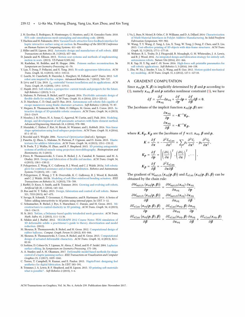
(a) (b) (c) (d)Rest shape Target shapes
Fig. 2. Geometry setup procedure, illustrated on a bending cylinder model with four target shapes. (a) The volume of the model is discretized using atetrahedral mesh, and segmented into regions with similar deformation behavior. (b) A pneumatic chamber is created for each region, and a directional field iscalculated along the principal Green strain directions. (c) A quad mesh is generated for each pneumatic chamber along the orientation field. (d) A framestructure is generated along the edges of every quad mesh, which will serve to stiffen the object.
simulation (Sec. 4.1); (2) constructing the penumatic chambers ac-cording to the simulation results S (Sec. 4.2); (3) generating theframe structure around the constructed pneumatic chambers suchthat the frame directions follow the principal Green strain directionsof deformations (Sec. 4.3).
4.1 Tetrahedral mesh generation and deformationWe first discretize the volume encompassed by M into a tetrahe-dral mesh S by a quality conforming Delaunay triangulation [Si2015]. For any boundary tetrahedron whose four vertices are on theboundary surface, to avoid tangling in the target shapes, we split itinto four tetrahedrons by inserting its center point, so that in thetarget shapes, the corresponding tetrahedrons have the freedom tobe untangled. Then we deform S to the target shapes to obtain thetarget tetrahedral meshes S1, . . . ,SK as follows.
Considering that the material used for soft robotics is hyperelasticand homogenous, we use the Neo-Hookean model [Sifakis andBarbič 2012] to guide the deformation. The strain energy densityon a single tetrahedron ti is defined as
Ψi =µi2
(tr(FTi F i ) − log
(det(FTi F i )
)− 3
)+λi8log2
(det(FTi F i )
).
Here F i is the deformation gradient, i.e., the linear transformationpart of the affine transformation from the resting-state tetrahedronti to its deformed version ti ; tr(·) the matrix trace operator. Theparameters of the Neo-Hookean model can be derived from Young’smodulus Ei and Poisson’s ratio νi associated with the material by(1):
µi =Ei
2(1 + νi ), λi =
Ei3(1 − 2νi )
. (1)
By summing the strain energy over the deformed tetrahedral mesh,the total elastic energy of the model is:
Eelas =∑ti ∈S
Ψi vol(ti ).
Here vol(ti ) is the volume of ti .For deforming S to the target poseMj , j ∈ {1, . . . ,K}, we assume
there exist exterior forces on the boundary vertices and the volumeis filled with the softest material available in our fabrication process.This artificial assumption gives us guidance for estimating the lay-out of chambers as shown in Sec. 4.2. The frame layout and materialoptimization in Sec. 4.3 and Sec. 5 also help the designed structureto reach the desired poses as closely as possible when real physical
simulation is taken into consideration. Thus by minimizing Eelaswith respect to the positions of interior tetrahedral vertices whileconstraining boundary vertices at their target positions inMj , wecan obtain the deformed tetrahedral mesh Sj . Note that when theminimum of Eelas is reached, the mesh is also at the force equi-librium state. In our implementation, we use the Newton methodto solve this minimization problem. During the optimization, weadd a multiple of the identity matrix to handle the non-positiveHessian [Nocedal and Wright 2006] and use linear search to avoidtangled tetrahedrons.
To accelerate the simulation, we use Laplacian smoothing to ob-tain the interior vertex positions while fixing the boundary verticesat the target shape and untangle the resulting mesh by a state-of-the-art tetrahedral untangling technique [Escobar et al. 2010], thenprovide the untangled mesh as the initialization to our optimization.By the above physical-based deformation, a series of tetrahedralmeshes S1, . . . ,SK can be obtained efficiently.
4.2 Chamber constructionThe tetrahedral meshes S1, . . . ,SK computed in Sec. 4.1 providethe deformation behaviors when the object is made of a single softmaterial and driven by exterior forces. By analyzing the volumechanges of each tetrahedron, we propose a segmentation-basedmethod to construct pneumatic chambers. The principles of chamberconstruction are simple: (1) regions with large volume changesshould become chambers; otherwise, the soft material on thoseregions cannot bear large stretch; (2) regions with increased volumesand decreased volumes should be clustered to different chambersfor separate pneumatic control.
Detecting rigid deformed regions. We first detect the tetrahedronsin S that undergo rigid motion in the deformations. A naïve way isto check whether the deformation of a tetrahedron is close to a rigidtransformation. However, this kind of detection is too local and itis hard to find continuous regions. We propose a greedy clusteringalgorithm to find rigid deformed regions:
(1) for every target tetrahedral mesh Sj , we randomly pick a seedtetrahedron tl and grow this region greedily by merging tetrahe-dron tm that is adjacent to this growing region if the Frobeniusnorm of the difference of the linear transformations betweenthem is smaller than a threshold, i.e., ∥F l − Fm ∥2F ≤ 0.03. Wekeep seeding and growing until no tetrahedron is left.
ACM Transactions on Graphics, Vol. 36, No. 6, Article 239. Publication date: November 2017.

Computational Design and Fabrication of Soft Pneumatic Objects with Desired Deformations • 239:5
(2) for each cluster inSj , if themean of its tetrahedron’s linear trans-formations F is close to a rotation transformation, i.e.max(|σ−1
min−1|, |σmax − 1|) ≤ rthres, we label the tetrahedron as rigid. Hereσmin,σmax are the minimal and maximal singular values of F .In our experiments, we set rthres = 0.01.
(3) For any tetrahedron inS, if all its deformed versions inS1, . . . ,SKhave the label rigid, we label it as always rigid and will use thehardest material to fill it in the fabrication.
Considering that in some cases parts of the boundary facets ofall the target shapes have no stretch or compression, we also needto keep them unchanged. So similar to the above tetrahedron clus-tering, we perform the same clustering on boundary triangle facets.For any triangle in S which is labeled as always rigid, we also labelthe tetrahedron that contains the triangle as always rigid and fill itwith the hardest material too. In Fig. 2(a), the detected always rigidregion is rendered in gray color for a bending cylinder model.
Chamber initialization. After identifying the rigid regions, we ini-tialize the chambers by clustering the tetrahedrons in the remainingregions according to their volume changes. To this end, for eachtetrahedron ti in S which is not labeled always rigid, we first com-pute its volume changes between the rest shape to each target shape:∆(j)i := vol(t(j)i ) − vol(ti ), j = 1, . . . ,K , where t (j)i is ti ’s correspond-
ing tetrahedron in Sj . We then assign a K-dimensional descriptorvector D(ti ) to ti whose k-th entry is chosen from {1, 0,−1}, where1 indicates that ti ’s volume increase is the largest at the k-th targetpose, −1 means that ∆(j)
i is negative, and 0 for others. For tetrahe-drons whose k-th entry of D are 1, their volume grows towardsthe k-th target shape and thus should be inflated and controlledseparately. Therefore, we group the tetrahedrons with the samelabel as a cluster. Since the deformation is smooth inside the objectvolume, the neighboring tetrahedrons always share the same labeland thus are grouped in one cluster. For a cluster that contains sev-eral isolated regions, we treat each isolated region as an individualcluster. In this way, we obtain a set of clusters, each of which is achamber candidate.In practice, we found that this cluster scheme generates many
small chamber candidates. Since an air tube needs to be connected toeach chamber, it is difficult to fabricate an object that includes manysmall chambers. We thus remove the small chamber candidates bymerging them to adjacent clusters. Specifically, for each cluster C ,we compute the ratio of its volume in the rest shape with respectto the total volume of all the non-rigid regions: Vr :=
∑t∈C vol(t)∑
t<r iдid vol(t) .
If Vr of a cluster is smaller than a threshold (0.02 in our currentimplementation), we merge it to a neighboring cluster that has themaximal volume among all the neighboring clusters. For all smallclusters, we execute this merging process according to descendingorder of Vr until no cluster can be merged.
Pneumatic deformation validation. Due to the pneumatic princi-ple, there must exist chambers whose volumes increase during thedeformation. We examine all the chamber clusters for whether oneof its volumes is increased from the rest state to the target state. Ifthere is no such cluster, the target deformations cannot be realizedby the soft pneumatic model and we ask the user to redesign the
target shapes. For example, a pure twisted cube (Fig. 8) cannot beachieved pneumatically, so we need to extrude the cube as wellwhen designing the target shape.
We also check the deformation on the boundary facets of S. For aboundary facet, denote its deformation gradients with respect to allthe targets by F 1, . . . , FK . If the principal Green strain directionsderived from these deformation gradients are very different (we setthe maximum angular deviation of directions to 20 degrees in ourexperiments), we label the facets as violated, since this would resultin a violation in frame structure generation (Sec. 4.3). If the totalarea of such violated facets is greater than 20% of the surface area,we also require the user to redesign the target shapes.
Chamber construction. Finally, we turn the resulting clusters intochambers. Regarding each cluster as a sub tetrahedral mesh, we ex-tract its boundary facets to form the boundary surface of the cham-ber. Since the extracted boundary surface is usually non-smooth andnon-manifold, we sample points from it and use Poisson reconstruc-tion [Kazhdan et al. 2006] to generate a relatively smooth manifoldmesh. The region surrounded by the mesh is the pneumatic chamber.
Chamber refinement. In practice, the thickness between chambersaffects the stretchability of the object. If the thickness is too small,the regions between chambers may easily break under pressure. Weexperimentally find that 6mm is a safe thickness value and is goodfor embedding the frame structure (which will be introduced later).We use Laplacian deformation [Sorkine et al. 2004] to refine theboundaries of the chambers. The refinement procedure is as follows.(1) For each boundary vertex v of a chamber, we find its nearest
point p on the neighboring chamber or the boundary surface S.If l := ∥v−p∥ ≤ 6mm (the safe thickness between chambers), welet v0 := v+ 6−l
2v−p∥v−p∥ be the target position of v in the Laplacian
deformation; otherwise the vertex is fixed in the deformation.(2) We apply Laplacian deformation to each chamber surface.(3) We repeat steps (1)&(2) until a safe thickness is achieved.Fig. 2(b) illustrates the four constructed chambers. Alternative
refinement strategies can be applied instead, such as computing aself-intersection free offset surface.
4.3 Frame structure generationIf a soft object is fabricated using a homogeneous material, whichreveals isotropic stretchability, it may become very fat locally wheninflated, which does not conform to the desired shape. To control thedeformation when inflating, it is necessary to use multiple materialsto achieve anisotropic behaviors. One way to determine the materialproperty is to treat the material properties of all the tetrahedronsas unknowns and solve a nonlinear optimization problem [Skouraset al. 2013]. However, the problem could contain a lot of variablesand the system is under-determined if there are no regularizationterms in the objective function, thus it would be costly to solve theproblem and regularization terms must be included. Inspired by thefiber structure used in soft robotics and the truss structure usedin architecture, we choose to embed a frame structure around thechamber boundary to achieve anisotropic deformation behaviors.As a design criterion of the frame structure, the frame should
follow the principal Green strain directions as much as possible
ACM Transactions on Graphics, Vol. 36, No. 6, Article 239. Publication date: November 2017.

239:6 • Li-Ke Ma, Yizhong Zhang, Yang Liu, Kun Zhou, and Xin Tong
so that it can support the major interior forces. Since the principalGreen strain directions are orthogonal, they naturally form a crossfield. We use a field-guided approach [Bommes et al. 2009; Ebke et al.2013] to generate a quad mesh as the base of our frame structure.Since there are possibly several target shapes, the Green straintensor associated with the boundary triangles of a chamber maybe not unique. But note that since the chamber region is formed bytetrahedrons with similar volume change behaviors across differentdeformations, the deformations on the chamber boundary cannothave a large difference. Therefore, we simply pick the one withthe largest eigenvalues. Fig. 2(b) shows cross fields on a bendingcylinder model.Once the quad mesh is generated, we offset it outwards to the
boundary by 1.5mm and build a solid wireframe on the quad meshwith thickness 1mm. The wireframe is generated as follows: for eachquad edge with length le , a rectangular solid shape with thickness1mm and length 0.8le along the edge is generated; on each quadvertex, the surrounding points of the rectangular solid shapes forma convex hull; the union of rectangular solid shapes and convexhulls form the frame structure. Fig. 2(c&d) show the quad mesh andthe generated frame structure. Here, note that there is no need togenerate frames on the region between chambers and always rigidregions.There are two parameters in our frame structure generation: (1)
the expected quad edge length le in quadmeshing defines the densityof the frames; (2) the wireframe radius r defines the thickness offrames. In practice, we find that le = 6mm and r = 1mm are goodchoices for minimizing shape distortion during deformation. InSec. 8 we provide comparisons with other choices.
5 MATERIAL OPTIMIZATIONWith the geometric structure of the soft pneumaticmodel introducedin the previous section, in the following we describe the materialspace and our soft pneumatic model in Sec. 5.1 and show how toassign proper material properties to the model for achieving thedesired deformations by a physically-based optimization in Sec. 5.2.
5.1 Material space and pneumatic modelTetrahedralmesh generation. Since the boundary surfaces of cham-
bers and the frame structure are not consistent with the originaltetrahedral mesh, we need to regenerate the tetrahedral mesh forthe model. With the TetGen software [Si 2015], we compute a qual-ity Delaunay triangulation conforming to the boundary surfacesof chambers, the boundary surface of the frame structure and thesurface of M. The generated tetrahedral mesh is denoted by S.We transfer the always rigid label from S to S by labeling tetra-hedrons of S whose centers are inside the labeled tetrahedrons ofS. The labeling process should leave the tetrahedrons inside theframe structure untouched since the material properties of thesetetrahedrons will be optimized.
Material model. To achieve the desired deformation behaviors, thematerial properties of all of tetrahedrons in S should be specified.Consider that the material used in actual fabrication is a blend oftwo base materials with the same Poisson ratio: the soft material(Young’s modulus Esoft) and the stiff material (Young’s modulus
Estiff), we classify the tetrahedrons into three categories and settheir material model as follows.• For always rigid tetrahedrons, we use the stiff material for them,i.e., the hardest material to avoid isometric distortion.
• Inside the frame structure, there are two types of tetrahedrons:tetrahedrons whose centers are in the rectangular solid regiondefined by a quad edge, and tetrahedrons whose centers are inthe convex hull region defined by a quad vertex. We group tetra-hedrons according to the quad edge index and quad vertex index.Each group is assigned to a same blended material whose Young’smodulus is defined as Eblend = (1− β)Esoft + βEstiff. Here eachgroup has its own β for the later optimization.
• For the remaining tetrahedrons, we use the soft material for them,i.e. make them as soft as possible.
Pneumatic model. We also use the Neo-Hookean model to studythe pneumatic model. Different from Sec. 4.1, there is no exteriorforce on the boundary surface and the model is deformed by injectedair. In our system, the air pressure can be controlled and is keptfixed for each target. For each pneumatic chamber Ci , we denote Vias its volume along a deformation and pi as the corresponding airpressure. Also, we denoteV0 as the volume surrounded by the outersurface and p0 the environment air pressure, which is a standardatmosphere in our experiments. Let X denote the rest positions ofthe vertices of the tetrahedral mesh, x the deformed vertex positions,and β the set of Young’s modulus interpolating parameters of theframe structure. Define p = [p1,p2, · · · ]T and V = [V1,V2, · · · ]T .The total elastic energy of our pneumatic system is:
Eelas(x , β) :=∑ti
Ψ(F i (x); β) vol(ti ).
The total potential energy of the system is:
Esys(x ,p, β) = Eelas(x , β) − pTV (x) + p0V0(x).
When the system is in quasi-equilibrium, x satisfies (2):
xeq = argminx
Esys(x ,p, β). (2)
Namely xeq, β and p satisfies nonlinear constraint (3):
f :=(− ∂Eelas∂x
+ pT∂V
∂x− p0∂V0∂x
) ����x=x eq(p,β )
= 0. (3)
For a given rest state X with material parameter β , the vertexpositions become xeq(p, β) when inflated with air pressure p atits equilibrium. The computation of xeq is similar to the physicalsimulation described in Sec. 4.1. In our work, we take the quasi-static assumption that the model is inflated gradually so that at anymoment the system is always at its equilibrium.
5.2 Numerical optimizationThe goal of our work to let the soft pneumatic model reach the de-sired shapes while maintaining a state of equilibrium. We formulatethe problem as a constrained optimization problem: the objectiveshould measure the difference between the deformed shape and thetarget, with the constraint of force equilibrium. Besides the basic
ACM Transactions on Graphics, Vol. 36, No. 6, Article 239. Publication date: November 2017.

Computational Design and Fabrication of Soft Pneumatic Objects with Desired Deformations • 239:7
objective, we also would like to minimize the total work of the pneu-matic device, to save energy and avoid large air pressure which maycause damage to the chambers. We design the objectives as follows.
Surface mismatch energy. We define the boundary mismatch en-ergyW (j)
match as the integration of the point-wise squared Euclideandistance between the deformed shape and the target shape Mjover the surface. Denote the boundary vertices of S by Xb , theirassociated areas by sb (1/3 area of their one-ring neighborhood),its deformed positions by x (j) |b , and its target positions by X (j) |b .W
(j)match can be formulated as:
W(j)match(x
(j)) := (x (j) |b −X (j) |b )T diag(sb )(x (j) |b −X (j) |b ).
Total work energy. For our pneumatically actuated model, all thework is done by air pumped into the pneumatic chambers. Assumethat during the inflation procedure, the air pressure changes alongpath p(s), s ∈ [0, 1]. Taking the quasi-equilibrium assumption, wecan get the deformation path with respect to the targetMj :
x (j)(s) = xeq(p(j)(s), β),
V (j)(s) = V (x (j)(s)),
E(j)elas(s) = Eelas(x (j)(s), β).
So the whole work accumulated is∫ 1
s=0(p(j) − p0)T dV (j)(s) =
∫ 1
s=0(p(j) − p0)T
∂V (j)
∂xdx (j)(s)
= E(j)elas(s) + p0
(V(j)0 (s) −
∑iV (j)i (s)
)�����10.
Here p0 := [p0,p0, · · · ]T denotes the initial air pressure on all thechambers. Since V (j)
0 (s) − ∑i V
(j)i (s) is the volume of the material,
which changes little since Poisson’s ratio effect can be ignored, sothe total pneumatic work is roughly equal to the total elastic energy.
Numerical optimization. We aggregate the mismatch energies andtotal work energies to form the objective function. Theminimizationis formulated as follows:
minβ,p (1), ...,p (K )
K∑j=1
W(j)match
(xeq(p(j), β)
)+
αK∑j=1
(Eelas
(xeq(p(j), β), β
))2.
Here,xeq(p(j), β) is plugged into the objective due to the quasi-staticassumption.
In our experiments, the default α is 0.001. Notice that since all theβs should be inside the interval [0, 1], we express them by the sig-moid function β := 1
1+e−t to make the above minimization problemunconstrained. The initial values of all the βs are set to 0.5 and theinitial air pressure is a standard atmosphere. We minimize the ob-jective by the Gauss-Newton method. Note that after each iterationof the Gauss-Newton method, x (j)eq should be updated by solving (2).In the appendix, we provide the details of gradient computation fornumerical optimization.
Air pressure pumpAir tank
Atmosphere
Micro-controller
Electric valve pair
Chamber
PC
Air tube
A B
Control signal
Fig. 3. The control scheme of one pneumatic chamber. A pneumatic chambercan inflate or exhaust air by changing the status of the electric valve pair,which can be controlled by PC.
6 PHYSICAL REALIZATIONAir channel setup. Once we have the interior geometry setup of
the object, we need to set channels for chambers so that they canconnect to the surface and are directed to air tubes for inflating orexhausting air. The thin channel (2mm radius) has little effect onthe deformation behavior of the resulting object based on our obser-vation, but the location of these channels may affect the appearanceand functionality of the soft object. We manually place the chan-nel for each chamber in our current implementation. The generalplacement guideline is to minimize its effects on object appearanceand make the channels pass through the hardest region as muchas possible. In the future we would like to develop a path findingalgorithm to construct channels automatically, similar to the workof [Savage et al. 2014].
Pneumatic control system. In our implementation, we adapt thepneumatic control system designed byHachisu and Fukumoto[2014],which contains an air pressure pump and an array of electric valvesthat are controlled by PC through micro-controllers. Fig. 3 showsthe control scheme of one pneumatic chamber. The compressedair of the pump is directed to an air tank, which serves as an airregulator. Then the regulated compressed air is connected to thepneumatic chamber through a 2 way-2 position electric inflationvalve (A in Fig. 3), controlled by PC through a micro-controllerinterface. When the valve is open, the pneumatic chamber will beinflated with high-pressure air quickly. The pneumatic chamberalso connects to the atmosphere directly through another valve, sothat when this valve is open, the pneumatic chamber will return toits rest state. To control objects with multiple pneumatic chambers,we connect each pneumatic chamber to a compressed air tank andatmosphere using an electric valve pair.The inflated volume of a pneumatic chamber is also determined
by the air pressure. Since the system has only one air pump, theair pressure should be no less than the highest pressure require-ment among the pneumatic chambers. So if a pneumatic chamberneeds lower air pressure, we need to switch the inflation valve offbefore the pressure exceeds the desired value. However, withoutthe help of pressure sensors, it is difficult to predict the transientpressure during the inflating process, because the speed of inflationis affected by many factors, such as air pressure, the volume of the
ACM Transactions on Graphics, Vol. 36, No. 6, Article 239. Publication date: November 2017.

239:8 • Li-Ke Ma, Yizhong Zhang, Yang Liu, Kun Zhou, and Xin Tong
Fig. 4. The heart model is split into three parts for gluing.
pneumatic chamber, the fractional volume of air tubes, and others.So in our current implementation, we do not control the air pressureexplicitly. Instead, we record the inflation time of the chambers thatcan achieve the target deformation and control the inflation timeto repeat the deformations. In the future, we would like to embedsensors inside each chamber, so that the pressure in each chambercan be controlled precisely and the target shape can be achievedwith high accuracy.
3D printing. For fabrication, we use a Stratasys Connex350 multi-material 3D printer with two base materials: VeroBlackPlus (rigid)and TangoPlus (flexible). The 3D printer provides ten materials (in-cluding two base materials and eight interpolated materials) andtheir physical parameters can be found in the literature [Bartlettet al. 2015]. Among the ten materials, we simply take the one closestto the optimized material property for printing. Since the pneumaticchambers will be filled with the support material during 3D print-ing, we split the object into several parts, and print and glue themtogether. The splitting is designed manually (via boolean opera-tions) and the basic rule is that every cut plane should pass throughchambers and regions filled with the hardest material as much aspossible, so that supporting material can be easily removed and thesoft material region is less affected by the glue. Fig. 4 shows thesplitting results of the heart model used in Fig. 1.
7 EXPERIMENTAL RESULTSWe evaluate our method in designing and fabricating six soft pneu-matic objects. The number of target shapes varies from one to four.The computation is executed on a desktop PC with an Intel CoreI7-6000 CPU and 16GB memory. The statistics of computing thesemodels are listed in Table 1. The video in our supplemental materialdemonstrates the dynamic behaviors of our models.
7.1 Objects with one target shapeCylinder model. We provide three target shapes for a cylinder
model, including vertical stretch, bending, and horizontal expan-sion (see Fig. 5). Since the principal Green strain directions of thesedeformations are similar, we use the same frame structure for thesemodels and compute three soft pneumatic cylinders that can suc-cessfully achieve the desired deformations as shown in the figure.We also scan the inflated cylinders and reconstruct the mesh andcompare it with the desired target shapes. The geometric differencebetween two surfaces are color-coded on the right of the figure. Wecan see that the shapes of our results are very close to the targets.
Breathing frog. We design a frog model whose target shape mim-ics frog breathing (Fig. 6). Our method automatically generates thebuccal cavity as an empty space inside the frog head, and the mate-rial distribution is optimized so that we can physically realize theshape of a frog breathing. Since the body part is a rigid region, wecan use a less expensive FDM 3D printer to print the rigid part inwhite color and glue all the parts together.
Gripper. A gripper-like object (Fig. 7) is made by our method. Therest shape and the target shape approximate the pick-up functionof the gripper. We also demonstrate the capability of our pneumaticgripper by grasping some lightweight objects.
Twisted cube. Fig. 8 shows the fabrication result on a cube with atwisted target shape which rotates along the z-axis by 10 degreesand expands the volume a little to allow pneumatic-driven deforma-tion. Due to the weak fatigue strength of the material, we can onlyproduce a slightly twisted deformation. If we keep injecting air, thecube will continue to twist but the chamber will break.
7.2 Objects with multiple target shapesBeating Heart. Pneumatic soft objects are good for simulating
organs such as the heart. We design a heart model with two targetshapes to mimic heart beating. Our method finds two chambersfor the model, and the fabricated model under pneumatic controlreplicates the desired motion vividly. The design process and thefabrication result are illustrated in Fig. 1.
Bending cylinder. We add bending deformations in four directionsas the target shapes for a cylinder model (see Fig. 2). Our methodfinds four chambers. For each target deformation, by injecting airinto two chambers and releasing air from two other chambers, thesetarget deformations can be easily achieved as shown in Fig. 9.
8 DISCUSSION ON THE FRAME STRUCTUREIn this section, we give an extended discussion on the layout ofthe frame structure and its material optimization. We answer thefollowing questions with the support of our experiments.
Whether the frame structure is necessary? It is known that theair chamber presents only isotropic deformation behaviors if itssurrounding material is homogenous and isotropic. When inflatingair to such a chamber, the shape would grow isotropically and thetarget shape cannot be achieved. The 2nd row of Fig. 7 shows an ex-ample where we replace the frame structure with the homogenousmaterial. We can see that the middle regions of the resulting grippermodel would grow to a ball-like shape. In our experiments, it alsofails to grasp other objects because it cannot reach the requireddeformation.
What is the optimal parameter setting for generating the framestructure? In Sec. 4.3 we provide our experimental optimal parame-ters le and r . Here we use an example to compare the results withother possible choices of these parameters. The model is a squaredtube with a vertically-stretched target. A chamber is embedded in-side the volume and the principal Green strain directions along theboundary of the chamber are the vertical and horizontal directions.
ACM Transactions on Graphics, Vol. 36, No. 6, Article 239. Publication date: November 2017.

Computational Design and Fabrication of Soft Pneumatic Objects with Desired Deformations • 239:9
0
4mm
Fig. 5. Cylinder model. From left to right: target shape, the frame structure whose color encodes the material type (for frame segments with the base softmaterial, they are not rendered), the fabricated object at the rest pose, the inflated object, the color coding of geometric errors between the inflated object andthe input target shape.
(a) (b)
(c) (d)
Fig. 6. A breathing frog. (a) is the rest shape of the frog and (b) is the targetshape. (c) is the fabricated object at rest pose and (d) is the inflated result.
We vary the expected quad edge length and the radius of the wire-frame to obtain several different frame structures. We then computetheir material properties and fabricate the model. Fig. 10 shows theinflated results. We can see that frame layouts which are too coarseor too narrow cannot constrain the expanded deformation betweenthe frames and the model with our optimal parameters has the leastshape deviation compared to others.
What is the advantage of restricting the material optimization inthe frame structure? As we discussed earlier, the restriction reduces
the large material space, and proper material properties in the framestructure is also effective for achieving anisotropic deformation be-haviors. Here we use the cylinder model as an the example to showthe advantage. We compare two approaches: (1) our method (resultsare in Fig. 5); (2) the full-space method: treat all the material prop-erties in the volume as unknowns and use our solver to optimize.This latter setting is similar to the work of [Skouras et al. 2013] inprinciple that all the material properties associated with tetrahe-drons are unknowns in the optimization. We choose the same initialvalues of material properties for both methods for fair comparison.Considering that the number of tetrahedrons is large on this exam-ple and makes the solver extremely slow, we uniformly cluster thetetrahedrons into 1862 groups and let tetrahedrons belonging tothe same group have only one material property, then optimize allthese materials. We found that the optimized result of the full-spacemethod has a larger deviation from the target than ours, and thecomputation time is much higher since the number of variablesis still larger than ours. The numerical results can be seen fromTable 1:Cylinder(stretch) II, Cylinder(bend) II, Cylinder(expand) II.Furthermore, for the expansion target deformation, the fabricatedCylinder(expand) II model cannot reach the desired shape by pneu-matic deformation because the chamber is broken by the pressuredue to the poor local minima found by the full-space method.
ACM Transactions on Graphics, Vol. 36, No. 6, Article 239. Publication date: November 2017.

239:10 • Li-Ke Ma, Yizhong Zhang, Yang Liu, Kun Zhou, and Xin Tong
Fig. 7. Gripper model. 1st row: the rest shape and the inflated shape withthe frame structure. 2nd row: the rest shape and the inflated shape withoutthe frame structure. The joint region is inflated to a ball-like shape due tothe loss of anisotropic control. 3rd row: the gripper model computed by ourmethod can grasp lightweight objects.
(a) (b)
Fig. 8. Twisted cube model: the fabricated rest shape (a) and the inflatedshape (b).
Fig. 9. Bending cylinder. From left to right: rest shape, bend-left, bend-right,bend-backward, bend-forward. The dynamic behavior of the model underpneumatic control can be observed clearly in the accompanying video.
We also examine the effects of randomized initializations. Wefound that the optimization based on our frame structure is very
Fig. 10. Varying the parameters for generating different frame structuresfor a vertically stretched model. 1st row: varying le ; 2nd row: varying r .The leftmost figures in the two rows are the same and are from our defaultparameter setting.
Fig. 11. Cylinder models computed by the full space method. 1st row: therest shapes; 2nd row: the corresponding inflated shapes. The expansioncylinder breaks before reaching the target pose.
robust to different initializations and the results are always similar,but the optimization with respect to the full space is easily trappedin poor local minima. We further tried to provide our optimizedresult as the initialization to the full space optimization, and foundthat it is very close to a local minimum. This fact reveals the efficacyof using the frame structure in the design and fabrication of softpneumatic objects.
9 CONCLUSIONSWe present a novel method for design and fabrication of soft pneu-matic objects with desired deformations. By analyzing the deforma-tions of the mesh, we generate pneumatic chambers and constructthe frame structure. The material properties and the air pressureare optimized by physically-based optimization for achieving de-sired deformation behaviors. We fabricate soft pneumatic objectsby 3D printing and reproduce the input deformations with a con-trolled pneumatic system. The efficacy of our method is validatedand demonstrated on a set of 3D objects with different target shapes.
ACM Transactions on Graphics, Vol. 36, No. 6, Article 239. Publication date: November 2017.

Computational Design and Fabrication of Soft Pneumatic Objects with Desired Deformations • 239:11
Model # vert # tet # bvert # target # chamber # var-mat # iteration Opt. timing Hausdorff distance(s)
Cylinder(stretch) 4173 12602 4400 1 1 661 86 8m42s 4.18e-3Cylinder(bend) 4173 12602 4400 1 1 661 100 8m28s 4.62e-3Cylinder(expansion) 4173 12602 4400 1 1 661 20 3m38s 2.92e-2
Cylinder(stretch) II 4173 12602 4400 1 1 1862 54 28m57s 2.22e-2Cylinder(bend) II 4173 12602 4400 1 1 1862 53 30m39s 1.21e-2Cylinder(expansion) II 4173 12602 4400 1 1 1862 27 23m49s 2.44e-2
Breathing Frog 5602 20270 7222 1 1 46 12 26s 1.44e-2Gripper 8426 41449 4400 1 1 235 36 3m24s 2.24e-2Twisted Cube 13369 67783 5074 1 1 606 45 29m04s 3.00e-2Beating Heart 13477 57859 9950 2 2 777 36 33m31s 6.27e-3, 1.03e-2Bending cylinder 14130 62847 6104 4 4 765 59 3h30m57s 1.95e-2, 1.99e-2, 1.99e-2, 1.98e-2Table 1. Statistics and timings for our test models. From left to right: name of model, vertex number of the tetrahedral mesh, number of tetrahedrons, vertexnumber of the boundary surface, number of target shapes, number of pneumatic chambers, number of unknown material properties, iteration number, timingfor optimization, Hausdorff distance between the target shape and the simulation result (with respect to bounding box diagonal). The computational time ofgeometry setup for each model is less than two minutes.
There are serveral research directions we would like to exploreto enhance our method.
Achievable deformations. In Sec. 4.2, we provide a method todetect whether the user-provided deformation can be realized bypneumatic soft robotics. However, the method does not provide afull characterization of valid deformations and the user needs someskill and manual work to modify the target shapes. An automaticmethod that can guide the design of target shapes would benefitusers. Another direction to improve our method is to enable activeair deflation which is not considered in our current approach.
Pneumatic system. As discussed earlier, using pressure sensorswill help us to control the pneumatic system automatically. It is alsointeresting to use small scale pneumatic devices and embed theminside the soft object, making it a self-contained soft robot.
Model fabrication. Currently we split the object into pieces toremove the supports from the 3D printed material and glue allthe pieces together manually. Since this manual step is tedious fornovice users, in the future, we would like to use water-dissolvablesupport material and wash away the support material through airchannels so that the splitting step can be reduced.
Frame structure. Our frame structure is based on the field-guidedquad meshing result whose edge orientations may have large de-viations from the input field. As an alternative, we can use ananisotropic quad-dominant mesh [Alliez et al. 2003; Lévy and Liu2010] for improvement. Microstructure [Schumacher et al. 2015]can also be applied to achieve more anisotropic properties.
Material blending. In our fabrication we choose from among tenavailable materials the one that is closest to the computed materialproperties. It would be possible to mix the ten materials to moreclosely approximate the computed material properties by halftone-like techniques.
Soft material. We find that the TangoPlus material cannot with-stand large stress and may crack after repeated deformation due toits weak fatigue strength [Vu et al. 2014]. Silicone rubber has betterfatigue strength than TangoPlus and our embedded frame structure
can help it to achieve anisotropy property. However, in practice,we find that the frame structure may penetrate or detach from thesurrounding silicone rubber after repeated deformation. These prac-tical issues need to be addressed, and the simulation should alsotake the fatigue strength into the consideration.
ACKNOWLEDGMENTSWe thank Taku Hachisu and Masaaki Fukumoto for sharing thepneumatic control system for adaption, Stephen Lin for proofread-ing the paper and the anonymous reviewers for their constructivefeedback. Kun Zhou is supported by the National Program for Spe-cial Support of Eminent Professionals of China.
REFERENCESP. Alliez, D. Cohen-Steiner, O. Devillers, B. Lévy, and M. Desbrun. 2003. Anisotropic
polygonal remeshing. ACM Trans. Graph. 22, 3 (2003), 485–493.M. Bächer, B. Bickel, D. L. James, and H. Pfister. 2012. Fabricating articulated characters
from skinned meshes. ACM Trans. Graph. 31, 4 (2012), 47:1–47:9.M. Bächer, S. Coros, and B. Thomaszewski. 2015. LinkEdit: interactive linkage editing
using symbolic kinematics. ACM Trans. Graph. 34, 4 (2015), 99:1–99:8.N. W. Bartlett, M. T. Tolley, J. T. B. Overvelde, J. C. Weaver, B. Mosadegh, K. Bertoldi,
G. M. Whitesides, and R. J. Wood. 2015. A 3D-printed, functionally graded soft robotpowered by combustion. Science 349, 6244 (2015), 161–165.
B. Bickel, M. Bächer, M. A. Otaduy, H. R. Lee, H. Pfister, M. Gross, and W. Matusik. 2010.Design and fabrication of materials with desired deformation behavior. ACM Trans.Graph. 29, 4 (2010), 63:1–63:10.
B. Bickel, P. Kaufmann, M. Skouras, B. Thomaszewski, D. Bradley, T. Beeler, P. Jackson,S. Marschner, W. Matusik, and M. Gross. 2012. Physical face cloning. ACM Trans.Graph. 31, 4 (2012), 118:1–118:10.
D. Bommes, H. Zimmer, and L. Kobbelt. 2009. Mixed-integer quadrangulation. ACMTrans. Graph. 28, 3 (2009), 77:1–77:10.
D. Chen, D. I. W. Levin, S. Sueda, and W. Matusik. 2015. Data-driven finite elements forgeometry and material design. ACM Trans. Graph. 34, 4 (2015), 74:1–74:10.
F. Connolly, C. J. Walsh, and K. Bertoldi. 2017. Automatic design of fiber-reinforcedsoft actuators for trajectory matching. PNAS 114, 1 (2017), 51–56.
R. Deimel and O. Brock. 2016. A novel type of compliant and underactuated robotichand for dexterous grasping. The International Journal of Robotics Research 35, 1-3(2016), 161–185.
Y. Dong, J. Wang, F. Pellacini, X. Tong, and B. Guo. 2010. Fabricating spatially-varyingsubsurface scattering. ACM Trans. Graph. 29, 4 (2010), 62:1–62:10.
H.-C. Ebke, D. Bommes, M. Campen, and L. Kobbelt. 2013. QEx: robust quad meshextraction. ACM Trans. Graph. 32, 6 (2013), 168:1–168:10.
Y. Elsayed, A. Vincensi, C. Lekakou, T. Geng, C. M. Saaj, T. Ranzani, M. Cianchetti, and A.Menciassi. 2014. Finite element analysis and design optimization of a pneumaticallyactuating silicone module for robotic surgery applications. Soft Robotics 2 (2014),255–262.
ACM Transactions on Graphics, Vol. 36, No. 6, Article 239. Publication date: November 2017.
239:12 • Li-Ke Ma, Yizhong Zhang, Yang Liu, Kun Zhou, and Xin Tong
J. M. Escobar, E. Rodriguez, R. Montenegro, G. Montero, and J. M. Gonzalez-Yuste. 2010.SUS code: simultaneous mesh untangling and smoothing code. (2010).
T. Hachisu andM. Fukumoto. 2014. VacuumTouch: attractive force feedback interface forhaptic interactive surface using air suction. In Proceedings of the SIGCHI Conferenceon Human Factors in Computing Systems. 411–420.
J. Hiller and H. Lipson. 2012. Automatic design and manufacture of soft robots. IEEETransactions on Robotics 28, 2 (2012), 457–466.
D. Jamele and N. Ellison. 2013. Motion seat systems and methods of implementingmotion in seats. (2013). US Patent 8,585,142.
M. Kazhdan, M. Bolitho, and H. Hoppe. 2006. Poisson surface reconstruction. InSymposium on Geometry Processing. 61–70.
Y. Lan, Y. Dong, F. Pellacini, and X. Tong. 2013. Bi-scale appearance fabrication. ACMTrans. Graph. 32, 4 (2013), 145:1–145:12.
C. Laschi, M. Cianchetti, B. Mazzolai, L. Margheri, M. Follador, and P. Dario. 2012. Softrobot arm inspired by the octopus. Advanced Robotics 26, 7 (2012), 709–727.
B. Lévy and Y. Liu. 2010. Lp centroidal Voronoi tessellation and its applications. ACMTrans. Graph. 29, 4 (2010), 119:1–119:11.
C. Majidi. 2013. Soft robotics: a perspective–current trends and prospects for the future.Soft Robotics 1 (2013), 5–11.
L. Malomo, N. Pietroni, B. Bickel, and P. Cignoni. 2016. FlexMolds: automatic design offlexible shells for molding. ACM Trans. Graph. 35, 6 (2016), 223:1–223:12.
A. D. Marchese, C. D. Onal, and D. Rus. 2014. Autonomous soft robotic fish capable ofescape maneuvers using fluidic elastomer actuators. Soft Robotics 1 (2014), 75–87.
V. Megaro, B. Thomaszewski, M. Nitti, O. Hilliges, M. Gross, and S. Coros. 2015. In-teractive design of 3D-printable robotic creatures. ACM Trans. Graph. 34, 6 (2015),216:1–216:9.
P. Moseley, J. M. Florez, H. A. Sonar, G. Agarwal, W. Curtin, and J. Paik. 2016. Modeling,design, and development of soft pneumatic actuators with finite element method.Advanced Engineering Materials 18, 6 (2016), 978–988.
P. Musialski, C. Hafner, F. Rist, M. Birsak, M. Wimmer, and L. Kobbelt. 2016. Non-linearshape optimization using local subspace projections. ACM Trans. Graph. 35, 4 (2016),87:1–87:13.
J. Nocedal and S. Wright. 2006. Numerical Optimization (2nd ed.). Springer.J. Panetta, Q. Zhou, L. Malomo, N. Pietroni, P. Cignoni, and D. Zorin. 2015. Elastic
textures for additive fabrication. ACM Trans. Graph. 34, 4 (2015), 135:1–135:12.B. N. Peele, T. J. Wallin, H. Zhao, and R. F. Shepherd. 2015. 3D printing antagonistic
systems of artificial muscle using projection stereolithography. Bioinspiration andBiomimetics 10, 5 (2015).
J. Pérez, B. Thomaszewski, S. Coros, B. Bickel, J. A. Canabal, R. Sumner, and M. A.Otaduy. 2015. Design and fabrication of flexible rod meshes. ACM Trans. Graph. 34,4 (2015), 138:1–138:12.
P. Polygerinos, Z. Wang, K. C. Galloway, R. J. Wood, and C. J. Walsh. 2015a. Soft roboticglove for combined assistance and at-home rehabilitation. Robotics and AutonomousSystems 73 (2015), 135 – 143.
P. Polygerinos, Z. Wang, J. T. B. Overvelde, K. C. Galloway, R. J. Wood, K. Bertoldi,and C. J. Walsh. 2015b. Modeling of soft fiber-reinforced bending actuators. IEEETransactions on Robotics 31, 3 (2015), 778–789.
J. Rieffel, D. Knox, S. Smith, and B. Trimmer. 2014. Growing and evolving soft robots.Artificial life 20, 1 (2014), 143–162.
D. Rus and M. T. Tolley. 2015. Design, fabrication and control of soft robots. Nature521, 7553 (2015), 467–475.
V. Savage, R. Schmidt, T. Grossman, G. Fitzmaurice, and B. Hartmann. 2014. A Series ofTubes: adding interactivity to 3d prints using internal pipes. In UIST. 3–12.
C. Schumacher, B. Bickel, J. Rys, S. Marschner, C. Daraio, and M. Gross. 2015. Mi-crostructures to control elasticity in 3D printing. ACM Trans. Graph. 34, 4 (2015),136:1–136:13.
H. Si. 2015. TetGen, a Delaunay-based quality tetrahedral mesh generator. ACM Trans.Math. Softw. 41, 2 (2015), 11:1–11:36.
E. Sifakis and J. Barbič. 2012. SIGGRAPH 2012 Course Notes: FEM simulation of3D deformable solids: a practitioner’s guide to theory, discretization and modelreduction. (2012).
M. Skouras, B. Thomaszewski, B. Bickel, and M. Gross. 2012. Computational design ofrubber balloons. Comput. Graph. Forum 31 (2012), 835–844.
M. Skouras, B. Thomaszewski, S. Coros, B. Bickel, and M. Gross. 2013. Computationaldesign of actuated deformable characters. ACM Trans. Graph. 32, 4 (2013), 82:1–82:10.
O. Sorkine, D. Cohen-Or, Y. Lipman, M. Alexa, C. Rössl, and H.-P. Seidel. 2004. Laplaciansurface editing. In Symposium on Geometry Processing. 175–184.
A. A. Stanley and A. M. Okamura. 2017. Deformable model-based methods for shapecontrol of a haptic jamming surface. IEEE Transactions on Visualization and ComputerGraphics 23, 2 (2017), 1029–1041.
C. Torres, T. Campbell, N. Kumar, and E. Paulos. 2015. HapticPrint: designing feelaesthetics for digital fabrication. In UIST. 583–591.
B. Trimmer, J. A. Lewis, R. F. Shepherd, and H. Lipson. 2015. 3D printing soft materials:what is possible? . Soft Robotics 2 (2015), 3–6.
I. Vu, L. Bass, N. Meisel, B. Orler, C. B.Williams, and D. A. Dillard. 2014. Characterizationof Mutli-Material Interfaces in PolyJet Additive Manufacturing. In Solid FreeformFabrication Symposium. 959–982.
W. Wang, T. Y. Wang, Z. Yang, L. Liu, X. Tong, W. Tong, J. Deng, F. Chen, and X. Liu.2013. Cost-effective printing of 3D objects with skin-frame structures. ACM Trans.Graph. 32, 5 (2013), 177:1–177:10.
M. Wehner, R. L. Truby, D. J. Fitzgerald, B. Mosadegh, G. M. Whitesides, J. A. Lewis,and R. J. Wood. 2016. An integrated design and fabrication strategy for entirely soft,autonomous robots. Nature 536 (2016), 451–466.
H. K. Yap, H. Y. Ng, and C.-H. Yeow. 2016. High-force soft printable pneumatics forsoft robotic applications. Soft Robotics 3, 3 (2016), 144–158.
L. Zhu, W. Xu, J. Snyder, Y. Liu, G. Wang, and B. Guo. 2012. Motion-guided mechanicaltoy modeling. ACM Trans. Graph. 31, 6 (2012), 127:1–127:10.
A GRADIENT COMPUTATIONSince xeq(p;X , β) is implicitly determined by β and p according to(2), namely xeq, β and p satisfies nonlinear constraint (3), we have
df =∂ f
∂xeqdxeq +
∂ f
∂pdp +
∂ f
∂βdβ = 0.
The Jacobians of the implicit function xeq(p, β) are:∂xeq∂p= −K−1Kp ,
∂xeq∂β= −K−1Kβ ,
where K ,Kp ,Kβ are the Jacobians of f w.r.t. xeq, β and p,
K =∂ f
∂x= − ∂
2Eelas∂x2
+∑ipi∂2Vi∂x2
− p0∂2V0∂x2,
Kp =∂ f
∂p=
[(∂V1∂x
)T,
(∂V2∂x
)T, · · ·
],
Kβ =∂ f
∂β= − ∂
2Eelas∂x∂β
.
The gradient ofWmatch(xeq(p, β)
)and Eelas
(xeq(p, β), β
)can be
obtained by the chain rule:∂Wmatch
(xeq(p, β)
)∂p
=∂Wmatch(xeq)∂xeq
∂xeq∂p
;
∂Wmatch(xeq(p, β)
)∂β
=∂Wmatch(xeq)∂xeq
∂xeq∂β
;
∂Eelas(xeq(p, β), β
)∂p
=∂Eelas(xeq, β)∂xeq
∂xeq∂p
;
∂Eelas(xeq(p, β), β
)∂β
=∂Eelas(xeq, β)∂xeq
∂xeq∂β+∂Eelas(xeq, β)
∂β.
ACM Transactions on Graphics, Vol. 36, No. 6, Article 239. Publication date: November 2017.