Embed Size (px)
Citation preview

Computational Analyses of Quasi-Isolated Bridges with Fusing Bearing Components
Evgueni T. Filipov – Graduate Research Assistant , Department of Civil & Environmental Engineering (CEE), University of Illinois
Jerome F. Hajjar – Professor, and Chair, CEE, Northeastern University
Joshua S. Steelman – Graduate Research Assistant , CEE, University of Illinois
Larry A. Fahnestock – Professor, CEE, University of Illinois
James M. LaFave – Professor, CEE, University of Illinois
Douglas A. Foutch – Professor Emeritus, CEE, University of Illinois
2011 ASCE SEI Structures CongressApril 16, 2011 - Las Vegas, Nevada
Illinois Departmentof Transportation
Illinois Centerfor Transportation
Computational Analyses of Quasi-Isolated Bridges with Fusing Bearing Components
Introduction IDOT Earthquake Resisting System (ERS): Recently developed & adopted design approach
tailored to typical Illinois bridge types (and in part addressing increased hazard levels in AASHTO) Primary objective: Prevention of span loss Three levels of design and performance:
» Level 1: Connections between super- and sub-structures designed to provide a nominal fuse capacity
» Level 2: Provide sufficient seat widths at substructures to allow for unrestrained superstructure motion
» Level 3: Plastic deformations in substructure and foundation elements (where permitted)
04/14/2011 2
Computational Analyses of Quasi-Isolated Bridges with Fusing Bearing Components
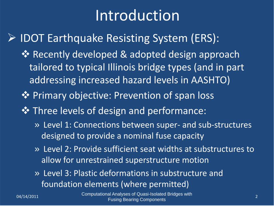
Quasi-Isolation for Bridges Typical bridge bearing systems designed to act as fuses to
limit the forces transmitted from the superstructure to the substructure Type I bearings: bearings with an elastomer to concrete sliding surface Type II bearings: elastomeric bearings with PTFE sliding surface L-shaped retainers: designed to limit service load deflections Low-profile bearings with steel pintles and anchorbolts
04/14/2011 3
Elastomeric bearing on concrete Elastomeric bearing with PTFE sliding surface
Low-profile fixed bearing
BRIDGE BEAM
STEEL TOP PLATE
TYPE I ELASTOMERICBEARING WITH STEELSHIMS
RETAINER
CONCRETESUBSTRUCTURE
ANCHOR BOLT
BRIDGE BEAM
TOP PLATE WITH POLISHEDSTAINLESS STEEL SURFACE
PTFE SURFACE
CONCRETESUBSTRUCTURE
RETAINER
ANCHOR BOLT
TYPE II ELASTOMERICBEARING WITH STEEL SHIMS
BRIDGE BEAM
PINTLE
LOW-PROFILE FIXEDBEARING
ANCHOR BOLT
CONCRETESUBSTRUCTURE
Computational Analyses of Quasi-Isolated Bridges with Fusing Bearing Components
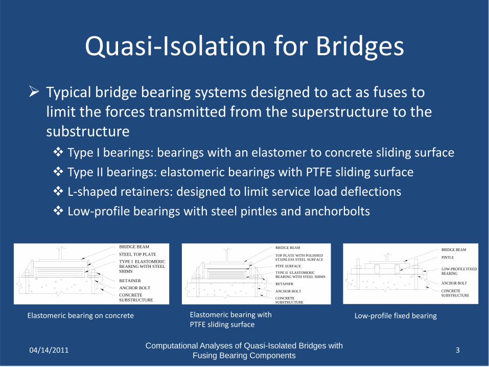
Bridge Prototype Model Three 50’ spans with six W27x84 Gr. 50 composite girders and
8” concrete deck 15’ Tall multi-column intermediate substructures Concrete abutments with backwalls and 2” gap from deck Pile foundations for all substructures
04/14/2011 4
Bridge Prototype Plan
Mesh Representation of OpenSees Model Bridge Prototype Elevation
42'-0
"
50'-0" 50'-0" 50'-0"
15'-0
"
LOW-PROFILEFIXED BEARINGS
TYPE I - ISOLATIONBEARINGS
W27x84
ABUTMENT
MULTI-COLUMNPIER
Type I - Bearings
Low-profile fixed bearings
Computational Analyses of Quasi-Isolated Bridges with Fusing Bearing Components
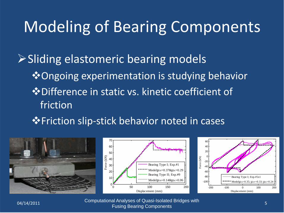
Modeling of Bearing Components
Sliding elastomeric bearing modelsOngoing experimentation is studying behaviorDifference in static vs. kinetic coefficient of
frictionFriction slip-stick behavior noted in cases
04/14/2011 5
-200 -100 0 100 200
-100
-80
-60
-40
-20
0
20
40
60
Displacement (mm)
Forc
e (k
N)
Bearing Type I; Exp.#5x1
Model:µSI=0.35; µSP=0.33; µK=0.24
0 50 100 150 2000
10
20
30
40
50
60
70
Displacement (mm)
Forc
e (k
N)
Bearing Type I; Exp.#1
Model:µSI=0.37&µK=0.29Bearing Type II; Exp.#9
Model:µSI=0.14&µK=0.06
Computational Analyses of Quasi-Isolated Bridges with Fusing Bearing Components
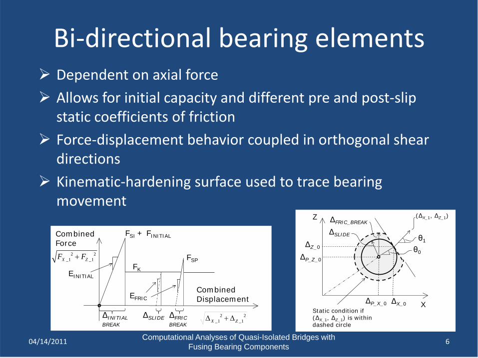
Bi-directional bearing elements Dependent on axial force Allows for initial capacity and different pre and post-slip
static coefficients of friction Force-displacement behavior coupled in orthogonal shear
directions Kinematic-hardening surface used to trace bearing
movement
04/14/2011 6
Combined Force
Combined Displacement
FK
ΔINITIALBREAK
ΔSLIDE
EINITIAL
ΔFRICBREAK
FSI + FINITIAL
2 2_1 _1X ZF F+ FSP
2 2_1 _1X Z∆ + ∆
EFRIC
Z
XStatic condition if (ΔX_1, ΔZ_1) is within dashed circle
ΔP_X_0 ΔX_0
ΔP_Z_0
ΔZ_0
ΔSLIDE
ΔFRIC_BREAK
θ0
θ1
(ΔX_1, ΔZ_1)
Computational Analyses of Quasi-Isolated Bridges with Fusing Bearing Components
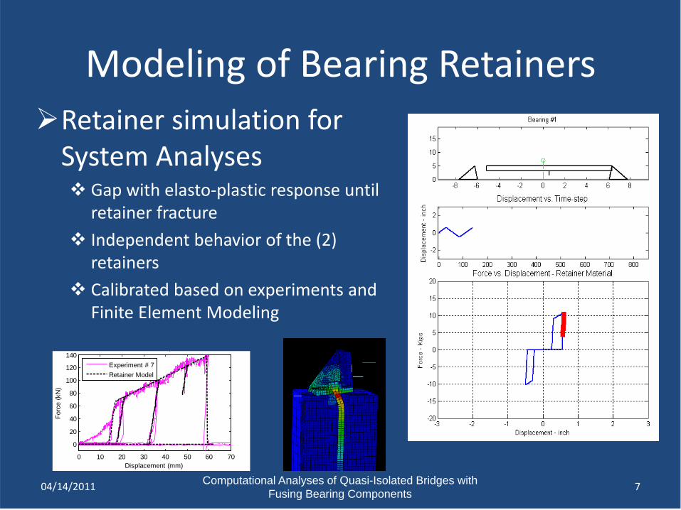
Retainer simulation for System Analyses Gap with elasto-plastic response until
retainer fracture Independent behavior of the (2)
retainers Calibrated based on experiments and
Finite Element Modeling
04/14/2011 7
0 10 20 30 40 50 60 70
0
20
40
60
80
100
120
140 p
Displacement (mm)
Forc
e (k
N)
Experiment # 7Retainer Model
Modeling of Bearing Retainers
Computational Analyses of Quasi-Isolated Bridges with Fusing Bearing Components
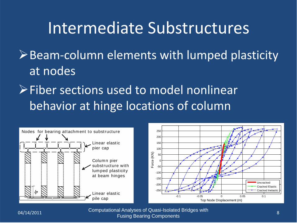
Intermediate SubstructuresBeam-column elements with lumped plasticity
at nodesFiber sections used to model nonlinear
behavior at hinge locations of column
04/14/2011 8
-0.1 -0.05 0 0.05 0.1
-250
-200
-150
-100
-50
0
50
100
150
200
250
Top Node Displacement (m)
Forc
e (K
N)
UncrackedCracked ElasticCracked Inelastic
Column pier substructure with lumped plasticity at beam hinges
Linear elastic pier cap
Nodes for bearing attachment to substructure
Linear elastic pile cap
lp
Computational Analyses of Quasi-Isolated Bridges with Fusing Bearing Components
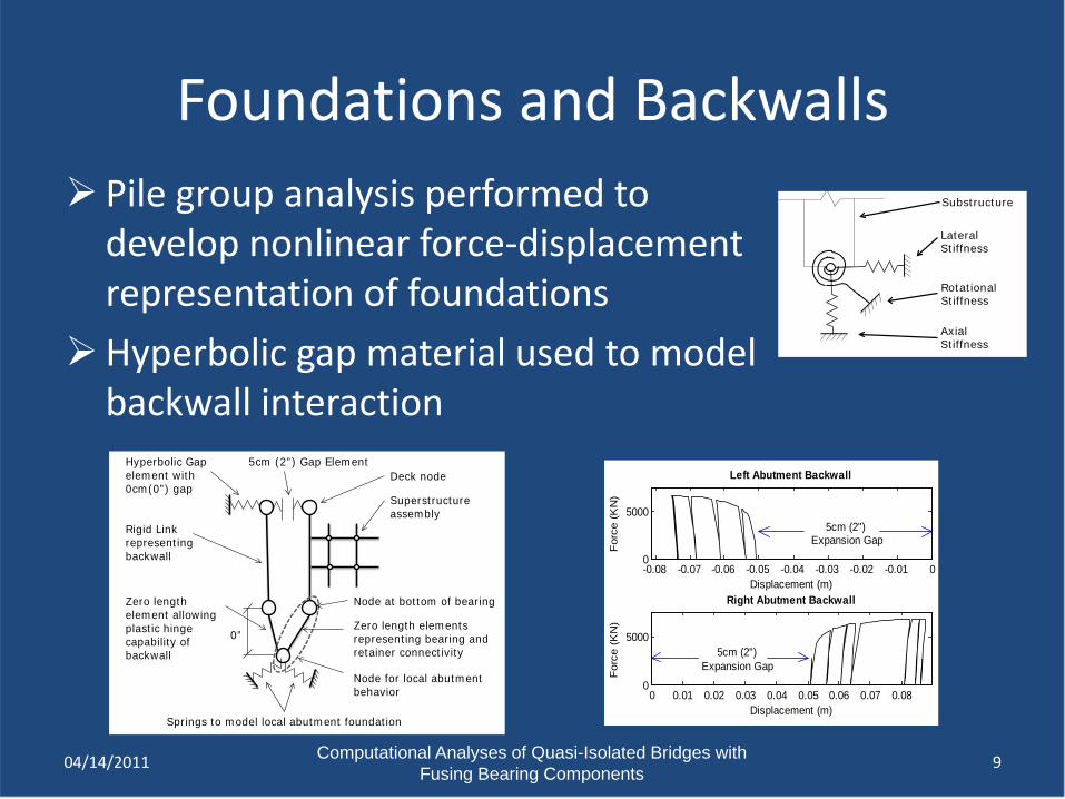
Foundations and Backwalls
04/14/2011 9
-0.08 -0.07 -0.06 -0.05 -0.04 -0.03 -0.02 -0.01 00
5000
Left Abutment Backwall
Displacement (m)
For
ce (
KN
)
5cm (2") Expansion Gap
0 0.01 0.02 0.03 0.04 0.05 0.06 0.07 0.080
5000
Right Abutment Backwall
Displacement (m)
For
ce (
KN
)
5cm (2") Expansion Gap
Substructure
Lateral Stiffness
Rotational Stiffness
Axial Stiffness
0”
Springs to model local abutment foundation
5cm (2”) Gap Element
Rigid Link representing backwall
Zero length element allowing plastic hinge capability of backwall
Hyperbolic Gap element with 0cm(0”) gap
Node at bottom of bearing
Zero length elements representing bearing and retainer connectivity
Node for local abutment behavior
Superstructure assembly
Deck node
Pile group analysis performed to develop nonlinear force-displacement representation of foundations
Hyperbolic gap material used to model backwall interaction
Computational Analyses of Quasi-Isolated Bridges with Fusing Bearing Components
Limit State Identification Longitudinal
Bearings Elastomer deformation & nonlinear behavior Yielding and fracture in anchor bolts & pintles of fixed bearings Sliding of bearings on substructure
Column and wall piers Cracking of concrete Yielding of reinforcement Crushing of concrete
Foundations Plastic deformation of backwall & backfill Plastic deformation of pile groups & pile caps
1004/14/2011
Computational Analyses of Quasi-Isolated Bridges with Fusing Bearing Components
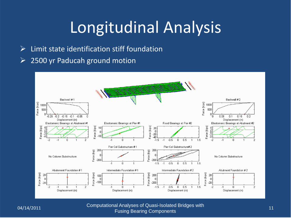
Longitudinal Analysis
11
Limit state identification stiff foundation 2500 yr Paducah ground motion
04/14/2011
Computational Analyses of Quasi-Isolated Bridges with Fusing Bearing Components
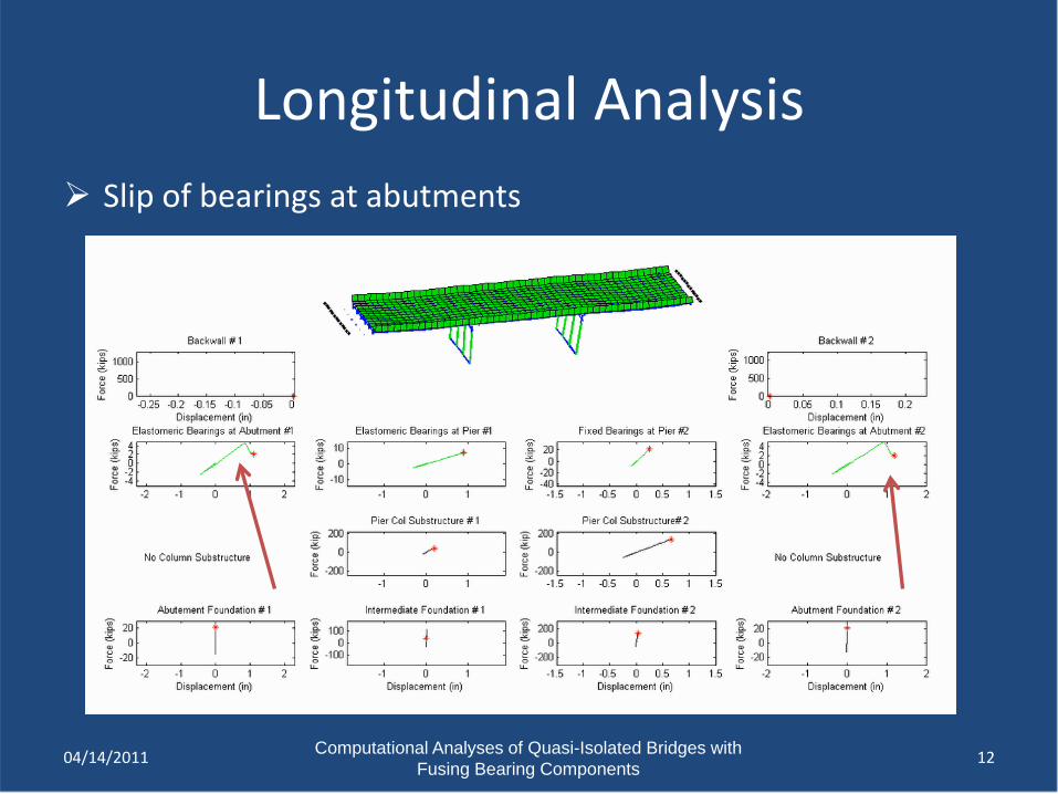
Longitudinal Analysis Slip of bearings at abutments
1204/14/2011
Computational Analyses of Quasi-Isolated Bridges with Fusing Bearing Components
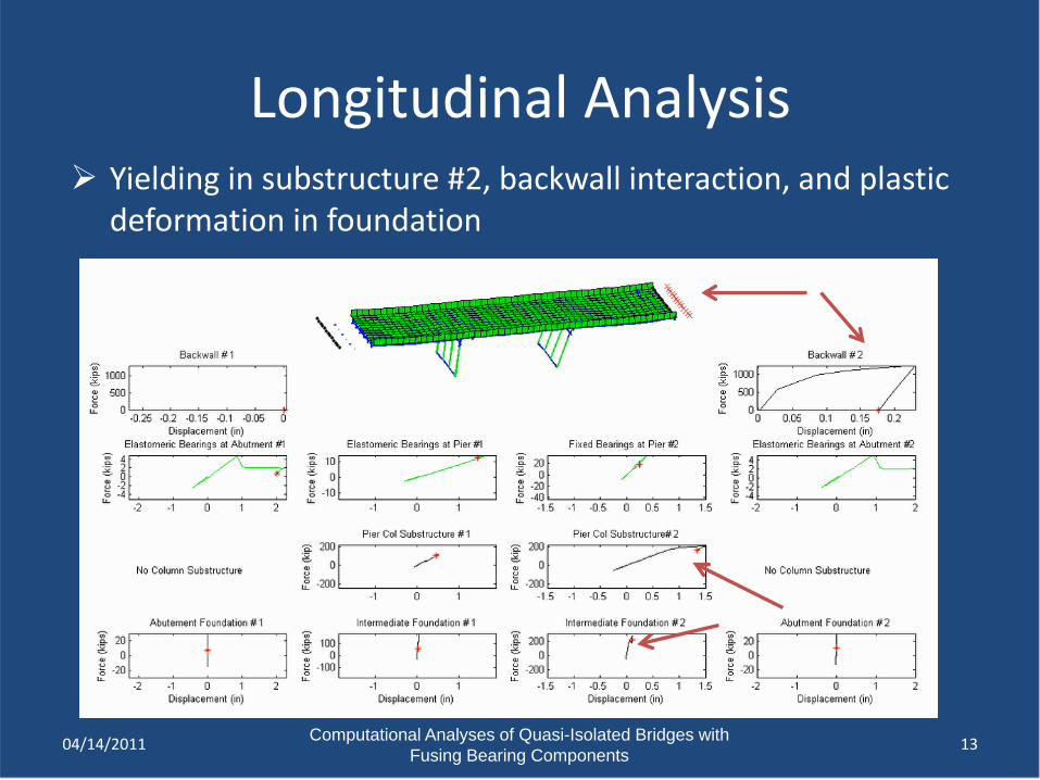
Longitudinal Analysis Yielding in substructure #2, backwall interaction, and plastic
deformation in foundation
1304/14/2011
Computational Analyses of Quasi-Isolated Bridges with Fusing Bearing Components
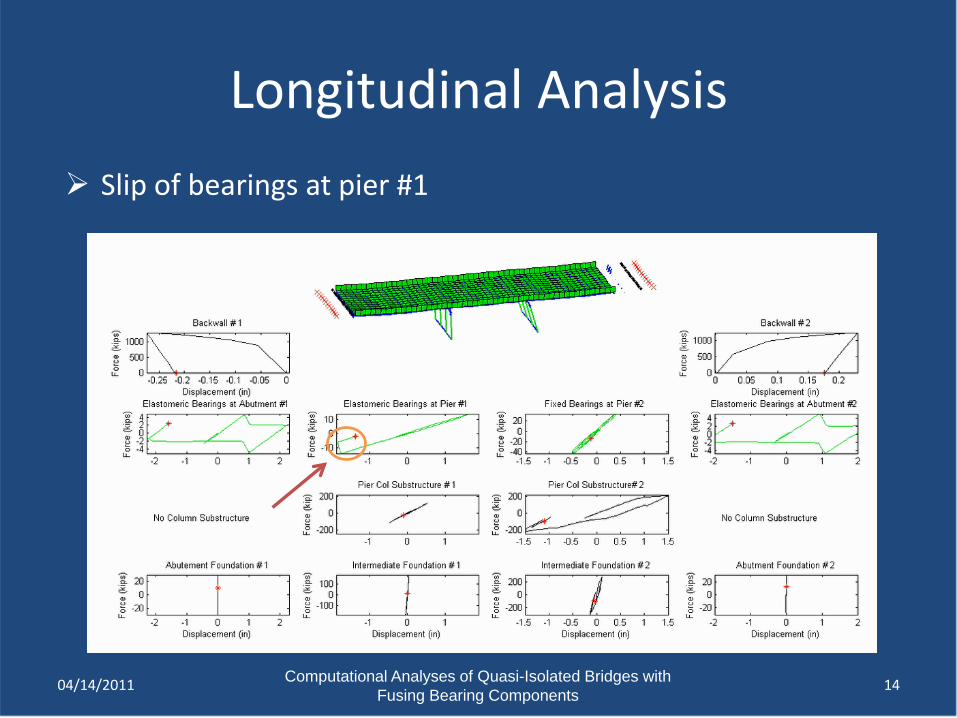
Longitudinal Analysis Slip of bearings at pier #1
1404/14/2011
Computational Analyses of Quasi-Isolated Bridges with Fusing Bearing Components
Limit State Identification Transverse
Bearings Elastomer deformation, retainer deformation with fracture &
nonlinear bearing behavior Yielding and fracture in anchor bolts & pintles of fixed bearings Sliding of bearings on substructure
Column and wall piers Cracking and/or crushing of concrete Yielding of reinforcement
Foundations Plastic deformation of pile groups & pile caps Possible interaction with backwall & backfill
1504/14/2011
Computational Analyses of Quasi-Isolated Bridges with Fusing Bearing Components
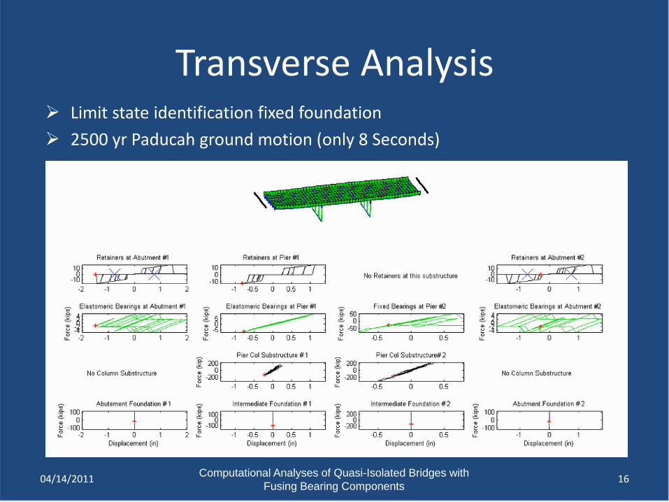
Transverse Analysis
16
Limit state identification fixed foundation 2500 yr Paducah ground motion (only 8 Seconds)
04/14/2011
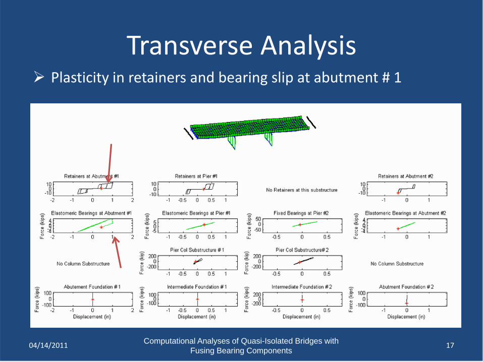
Computational Analyses of Quasi-Isolated Bridges with Fusing Bearing Components
Transverse Analysis Plasticity in retainers and bearing slip at abutment # 1
1704/14/2011
Computational Analyses of Quasi-Isolated Bridges with Fusing Bearing Components
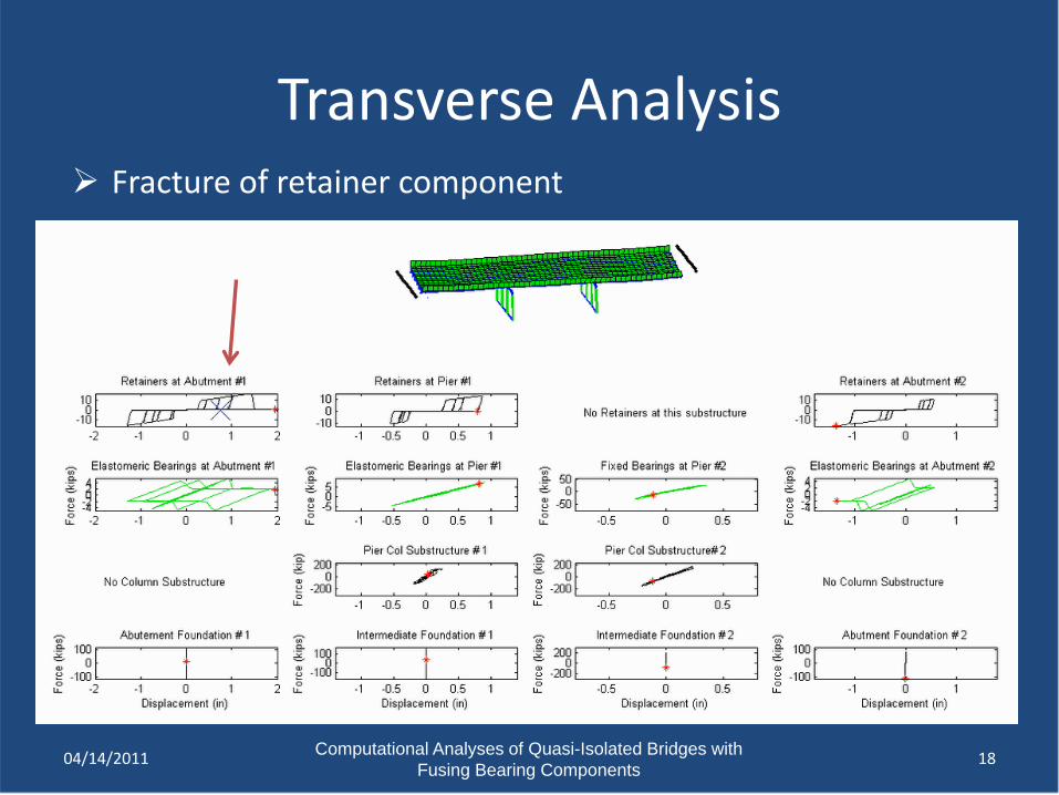
Transverse Analysis
18
Fracture of retainer component
04/14/2011
Computational Analyses of Quasi-Isolated Bridges with Fusing Bearing Components
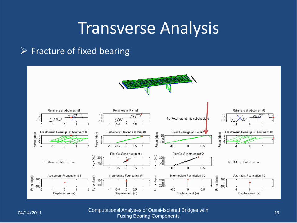
Transverse Analysis
19
Fracture of fixed bearing
04/14/2011
Computational Analyses of Quasi-Isolated Bridges with Fusing Bearing Components
System Analyses ObjectivesQuantification of expected value and dispersion for:Peak & residual bearing displacements Peak force demands on fuse componentsPeak force demands on sub-structuresSequence of fuse & systems failure
Parametric study to investigate influence of: Superstructure length and typeSubstructure height and type (column pier & wall)Isolation bearings (Type I & Type II) Foundation characteristics (stiff & soft soils)
04/14/2011 20
Computational Analyses of Quasi-Isolated Bridges with Fusing Bearing Components
Summary & ConclusionsNew element models represent key aspects of local
bearing behaviorsGlobal bridge model captures limit states for a
realistic three dimensional analysis Flexibility of elastomeric bearings and sliding of
bearings allows for quasi-isolated response Retainer elements and low-profile bearings need to
be carefully detailed to limit forces on substructures Backwalls have a significant contribution in limiting
longitudinal displacements
04/14/2011 21