Embed Size (px)
Citation preview

AIAA 2002-1369Computation of Wrinkle Amplitudesin Thin MembranesY.W. Wong and S. PellegrinoDepartment of Engineering, University of Cambridge,Cambridge CB2 1PZ, UK
43rd AIAA/ASME/ASCE/AHS/ASCStructures, Structural Dynamics, and
Materials Conference22-25 April 2002
Denver, COFor permission to copy or republish, contact the American Institute of Aeronautics and Astronautics1801 Alexander Bell Drive, Suite 500, Reston, VA 20191–4344

Computation of Wrinkle Amplitudes in ThinMembranes
Y.W. Wong∗ and S. Pellegrino†
Department of Engineering, University of Cambridge, Cambridge CB2 1PZ, UK
There is an increasing number of space missions in which it is proposed to use highaccuracy membrane structures and it is envisaged that some of these membranes will re-main partially wrinkled in their operational configuration. Previous studies have focussedonly on the stress distribution in wrinkled membranes, but for high accuracy applicationsthe amplitude and wavelength of the wrinkles becomes important. This paper presentsa non-linear finite-element simulation technique, where the membrane is modelled inABAQUS with S4R5 shell elements, which accurately predicts the wrinkle details. For arectangular membrane in shear it is found that the wrinkled pattern varies abruptly whenthe load magnitude is changed gradually. This simulation technique makes it possible to“look inside” a membrane and thus identify features of the complex behaviour of thinmembranes that need to be included in simple models, which can be very useful.
IntroductionThere is an increasing number of space missions in
which it is proposed to use high accuracy membranestructures with a variety of shapes and sizes. Examplesare sunshields for low-temperature telescopes, spacebased radars, inflatable reflector antennas and solarsails.Some of these membrane structures will remain par-
tially wrinkled in their operational configuration, andthis could potentially cause problems. For example,large wrinkles would compromise the performance ofa sunshield or reflector, and could make a solar sailuncontrollable. However, wrinkles of smaller magni-tude may be acceptable and, indeed, may even havebeneficial effects, such as increasing the out-of-planestiffness or the vibration damping of the membrane.This paper presents a computational study of a
wrinkled membrane in shear, a problem for which sev-eral solutions and experimental results have alreadybeen published. Initially the aim of this study wasto explore the accuracy and robustness of a numericalsimulation in which the membrane is modelled witha fine mesh of shell elements. It was later discov-ered that —due to the finite length of the membrane—the number of wrinkles varies abruptly with the sheardisplacement and this behaviour has the effect of in-troducing a certain amount of hysteresis in the system.The same numerical tools were then used to studythe mode-jumping instability associated with this be-haviour. Apart from being an interesting exampleof complex post-buckling response, it is possible thatin future this behaviour could be exploited, e.g. fordesigning membrane structures with high vibration
∗Research Student.†Professor of Structural Engineering, Associate Fellow
AIAA. [email protected] c© 2002 by S. Pellegrino. Published by the American
Institute of Aeronautics and Astronautics, Inc. with permission.
damping.The paper begins with a brief review of previous
studies of wrinkled membranes, which so far have fo-cussed mainly on identifying the wrinkled regions anddetermining the magnitude of the tensile principalstresses. An analytical study by the current authors—leading to approximate expressions for the wrinklewavelength and amplitude of infinitely long, uniformlysheared membranes— and an experimental study ofsquare membranes subject to tension and shear, areparticularly relevant to the present study.Next, a non-linear finite-element simulation tech-
nique is presented, where the membrane is modelledin ABAQUS with S4R5 shell elements. The simula-tion consists of three main parts, namely (i) setting upan initial, lightly prestressed membrane; (ii) carryingout an eigenvalue analysis leading to the imperfectionmodes that are seeded into the membrane; and (iii)a post-wrinkling analysis with hand-tuned numericalstabilisation to go past the instabilities associated withmode jumping.The following section presents a detailed numerical
study of a particular rectangular membrane. Its over-all behaviour is bilinear, depending on whether themembrane is flat or wrinkled, and is determined purelyby the tensile principal stresses in the membrane.However, a more in-depth study of the ABAQUS re-sults shows a complex variation in the shape of themembrane and the associated compressive stresses.Also, cycling the shear displacement back and forthproduces an envelope of response curves —not a sin-gle one— thus indicating that any particular solutionis unlikely to be unique.Two separate validation studies are then presented,
for a rectangular membrane in shear and a squaremembrane in tension and shear.A discussion concludes the paper.
1 of 11
American Institute of Aeronautics and Astronautics Paper 2002-1369

L
H
2λ
x
y δ
Fig. 1 Sheared Kapton foil with extensive wrin-kling.
BackgroundConsider a thin, rectangular membrane of length L
and height H. Let the horizontal edges be attached torigid blocks held at a fixed distance and the verticaledges be free, and impose a purely horizontal transla-tion of one of the two blocks. After only a very smalldisplacement, wrinkles start to form in the membraneand, as the displacement is increased, the number ofwrinkles increases and the out-of-plane deformationalso increases.Figure 1 shows a photograph of such a membrane.
In the central part the wrinkles form a regular pattern,and the wavelength of the wrinkles, i.e. the separationbetween two consecutive troughs or crests, will be de-noted by 2λ, see Figure 1.Much work has already been done on the wrin-
kling of membranes; this work can be broadly dividedinto three different categories, which will be briefly re-viewed next.
Analytical Approach
Most analytical studies so far have assumed thatmembranes have negligible bending stiffness and henceare unable to carry any compressive stresses.The classical approach is the tension field theory,
first introduced in 1929[1] for the analysis of thin websin I-beams that are allowed to go much beyond theirinitial buckling load. In its original form, this the-ory considered a set of parallel wrinkle lines but latera simpler geometrical formulation was proposed,[2]
which allowed for non-parallel tension rays. A furthergeneralization[3, 4] of this theory showed that the di-rection of the tension rays maximizes the (stretching)strain energy in the membrane. Closed form solutionsfor membranes with different shapes and anisotropicmembranes were developed.An alternative approach has been proposed for
partly wrinkled membranes,[5] such as a pressurizedcylindrical tube in pure bending. In this case the mem-brane can be divided into taut regions and wrinkledregions, and in the wrinkled region a variable Poisson’sratio can be defined such that there are no compres-sive stresses anywhere. Computer implementations of
this approach will be mentioned in the next section.A further approach considers finite elastic deforma-
tions of membranes with a special kind of strain energydensity function, known as a relaxed strain energy.This function is zero if at least one principal stress iscompressive.[6, 7] A formulation of this type has beenincorporated into standard finite-element schemes formembranes,[8] however only the in-plane deformationin the wrinkled regions can be predicted with this ap-proach. A generalisation of this theory in the contextof a saturated elasticity theory has been recently pro-posed.[9]
In the above solutions the membrane is alwaysmodelled as a no-compression material with negligiblebending stiffness, which amounts to assuming that awrinkled membrane will form an infinite number of in-finitesimally small wrinkles. Inspired by an analyticalsolution of the gravity-induced wrinkling in a hangingblanket,[10] which for the first time had considered acritical compressive stress in the membrane, we haverecently proposed a simple theory[11] to predict wrinklewavelengths and amplitudes for a rectangular mem-brane in uniform shear.This theory assumes that a membrane with Young’s
Modulus E, Poisson’s ratio ν, and thickness t carriesa uniform, compressive principal stress, σ2, equal tothe buckling stress of an infinitely wide, thin plate oflength λ
σ2 = − π2Et2
12(1− ν2)λ2 (1)
Based on this assumption, it can then be shown thatthe wrinkle half-wavelength, λ, of a membrane subjectto a shear displacement δ, as shown in Figure 1, andhence to a shear angle, γ, defined by
γ = δ/H (2)
is accurately predicted by
λ =
√πHt√
3(1− ν2)γ(3)
The wrinkle amplitude, A, is given by
A =
√2(1− ν)Ht
√γ
π√3(1− ν2)
(4)
Hence, λ is inversely proportional and A directly pro-portional to the fourth root of the shear angle, andboth of them are directly proportional to the squareroots of the length and thickness of the membrane.Note that both quantities are independent of theYoung’s Modulus of the membrane.
Numerical Approach
Closed-form solutions based on the theoretical ap-proaches described in the previous section exist onlyfor simple boundary conditions. For more complex
2 of 11
American Institute of Aeronautics and Astronautics Paper 2002-1369

geometries, numerical solutions are the only viable op-tion. The first finite element algorithm to incorporatewrinkling theory[12, 13] iteratively modified the mem-brane stiffness until all compressive stresses had beeneliminated. Three different states of the membrane,namely taut, wrinkled, and slack were considered. Arecent extension of this approach[14] has implementeda user subroutine that exploits the powerful numericalsolvers currently available in commercial FE packages,e.g. ABAQUS and NASTRAN, and obtained success-ful predictions of the shape and pattern of the wrinkleregions in a square membrane subjected to point loadsand inflated balloons of different shapes.A different scheme that models the membrane as a
no compression material in a non-linear geometricalanalysis has been successful in simulating the shapesof inflated air-bags,[15] including the formation of somelarge “folds” in the surface and also of extensive wrin-kled regions.A penalty tension field parameter has been used to
approximate the stress state in a parachute during de-ployment; modelling issues, including the influence ofthe order of integration and local remeshing in thewrinkled regions, have been discussed.[16] A discretebar network model of simple membrane structures hasbeen proposed.[17]
After testing many different wrinkling criteria, sev-eral authors have concluded that a combined stress-strain criterion is the best way of modelling real wrin-kled membrane.A general feature of all of these numerical studies is
that they adopt a purely two-dimensional model of themembrane. This approach can accurately predict thestress distribution in the membrane, including wrin-kled regions, and also the extent of these regions, butit can provide no information on wrinkle details. Webelieve that the only way of addressing this shortcom-ing in full is by modelling the membrane with shellelements instead of membrane elements. Of course,this considerably increases the complexity of carryingout a successful simulation.
Experimental Approach
Early experiments on wrinkled membranes focussedon the measurement of overall response parameters,such as the end rotation of a pressurized cylinder inpure bending[5] or the torque-rotation relationship ofa stretched circular membrane attached to a centralhub.[5, 18]
Performing detailed measurements on thin mem-branes is not easy, mainly because high accuracynon-contact measurement apparatus is needed. A setof carefully planned experiments, including accuratemeasurements of wrinkle details, were carried out veryrecently on a square membrane subjected to differentcombinations of shear and tension forces.[19] These ex-periments showed that both the wrinkle amplitude and
the number of wrinkles increase with the applied shearforce, but decrease with the tension force. The reverserelationship was found between the wrinkle wavelengthand the applied forces. Selected results from these ex-periments will be used to validate our solution method,in the section Validation of Finite Element Results:Comparison with an Experiment.The measurement technique introduced by Jenkins
et al.[19] has been extended to square membranes sub-jected to four corner point loads, to include the effectof thermal gradients within the membrane.[20]
Finite Element Modelling TechniqueThe bending stiffness of a membrane, although very
small, plays a key role in determining the shape andamplitude of the wrinkles. It is essential to includethis stiffness in any model that aims to capture thiskind of detail, hence the obvious choice is to modelthe membrane with shell elements.All analyses presented in this paper were carried
out with the ABAQUS[21] commercial package. Thispackage offers several different shell elements, and pre-liminary runs were carried out with 3-node triangularand 4-node quadrilateral full integration general pur-pose elements (S3, S4); these elements have six degreesof freedom at each node. 4-node and 9-node reducedintegration thin shell elements (S4R5, S9R5), with fivedegrees of freedom per node, were also investigated.The S3 element uses constant bending and mem-
brane strain approximations, therefore a very finemesh is required to capture the bending deformationdue to wrinkling. Note that the fineness of the dis-cretisation that is required is related to the expectedwrinkling wavelength. The formulation of element S4is similar to S3 for bending, but the in-plane strainfield has been enhanced to eliminate shear locking ef-fects. This, however, has the effect of making theelement too stiff in-plane. Both S4R5 and S9R5 arethin shell elements with three in-plane translationsand two in-plane rotation components, and use re-duced integration with hourglass control to avoid shearlocking. Both elements can model thin shells fairlyaccurately and S4R5 was chosen since it is computa-tionally more economical. Also, in general it is bestto avoid higher-order elements in highly geometricallynon-linear problems.A wrinkling analysis is typically performed in three
stages, as follows, after —of course— defining the finiteelement mesh, type of elements, and material proper-ties.
Initial Conditions
The initial stage consists in applying a small uni-form prestress to the membrane, to stabilize it. Theshell elements are very thin and hence their bendingstiffness is so small that obtaining meaningful resultswhen in-plane loads are applied can be a real challenge.
3 of 11
American Institute of Aeronautics and Astronautics Paper 2002-1369

It is important that the amount of prestress applied atthis stage should be large enough to successfully steerthe subsequent buckling mode analysis, but withoutsignificantly affecting the final results.After applying the initial prestress, a static, geomet-
rically non-linear equilibrium check (*STATIC, NL-GEOM) is carried out, to allow a small re-distributionof the state of prestress, together with small in-planedisplacements.
Eigenvalue Buckling Analysis
The next step of the analysis consists in determiningthe buckling mode shapes of this lightly stressed mem-brane. These modes are then used to seed small im-perfections that will trigger the formation of wrinklesin the subsequent geometrically non-linear analysis.An eigenvalue buckling analysis (*BUCKLE) is used
to predict the possible wrinkling modes of the mem-brane subjected to its actual boundary conditions andloading. The loading is typically defined in terms of aset of applied forces or displacements at the edge of themembrane, and has to represent the loads on the realstructure. It is important that both the initial stressesand displacements from the previous stage of the anal-ysis, as well as those due to the applied load, shouldbe included in the calculation of the tangent stiffnessmatrix; this is done by default in ABAQUS. The eigen-values and eigenvectors of the tangent stiffness matrixcorrespond to the load magnitudes and shapes of thepossible wrinkling modes of the membrane.After computing the possible wrinkling modes, a lin-
ear combination of some selected eigenmodes is intro-duced as a geometrical imperfection into the structure.The eigenvectors corresponding to the lowest eigenval-ues are often those of greatest interest, and so normallythe imperfections that are seeded in a structure areobtained as linear combinations of these particulareigenvectors. However, the lowest eigenvalue corre-sponds to the first buckling load, i.e. the load whichcauses the first wrinkle to form; this is not the objec-tive of our study. The first wrinkle forms almost assoon as the load is applied, but we are interested infollowing the evolution of this first wrinkle, leading tothe formation of a second one, and so on until a largenumber of wrinkles is obtained. Therefore, we base ourchoice of the imperfection modes that are introducedin the membrane on the expected, final wrinkling pat-tern and so we choose those eigenmodes which moreclosely resemble the diagonal wrinkle pattern that weaim to predict.Once the appropriate eigenmodes shapes have been
chosen, geometrical imperfections in the form of out-of-plane deformations are introduced (*IMPERFEC-TION):
∆z = Σiwiφi (5)
where wi is the ith eigenmode and φi is a scaling fac-tor whose magnitude is chosen as a proportion of the
thickness of the membrane. Values between 1% and100% of the thickness have been used, considering dif-ferent imperfection magnitudes to test the sensitivityof the predicted response.
Post-wrinkling Analysis
A geometrically non-linear (*NLGEOM) incremen-tal analysis is carried out under edge displacementincrementation, using the Newton-Raphson solutionmethod. Since the equilibrium path of the wrinkledmembrane includes many unstable branches, each cor-responding to a localised snap-through due to theformation of an additional wrinkle, the only type ofsolution algorithm able —in theory— to compute theresponse of the structure in full is the Riks method.The response of the structure cannot be computedin full if the displacement is increased monotonically.However, all attempts to use the arc-length solutionmethod in ABAQUS (*RIKS) were unsuccessful —possibly because wrinkling is a highly localized typeof instability— and hence monotonic displacement in-crementation was the only remaining option.Automatic stabilization was provided through the
STABILIZE function available in ABAQUS. Thisoption automatically introduces pseudo-inertia andpseudo-viscous forces at all nodes when an instabil-ity is detected. Then, instead of continuing with thequasi-static analysis, ABAQUS automatically switchesto a dynamic integration of the equations of motion forthe structure, thus reducing the likelihood of numeri-cal singularities.The fictitious viscous forces that are introduced by
the stabilize function are calculated on the basis of themodel’s response in the first increment of the analysisstep, by assuming that the energy to be dissipated isa fraction of the strain energy during the first step.This fraction is called damping intensity and has adefault value of 2 × 10⁻⁴. To achieve good accuracy,it is generally desirable to set this parameter to thelowest possible value for which convergence can stillbe achieved.
Analysis of Membrane in ShearA rectangular membrane with the dimensions de-
fined in the section Background, see Figure 1 andTable 1, has been analysed for a 3 mm translationof the upper edge. Figure 2 shows the finite elementmesh; each element has approximately unit aspect ra-tio.The initial step stabilized the membrane by apply-
ing a uniform prestress σy = 1.7 N/mm2, which wasachieved by moving the upper edge by 0.05 mm in they-direction.Next, an eigenvalue buckling analysis was carried
out with a prescribed horizontal displacement of 3 mmat the upper edge. Earlier analyses had shown that theeigenmodes corresponding to eigenvalues smaller than
4 of 11
American Institute of Aeronautics and Astronautics Paper 2002-1369

Table 1 Properties of Kapton foil
Length, L (mm) 380Height, H (mm) 128Thickness, t (µm) 25Young’s Modulus, E (N/mm2) 3530Poisson’s ratio, ν 0.3Density, ρ (kg/mm3) 1.5× 10⁻⁶
δ = 3 mm
H = 128 mm
L = 380 mm
xy
z
Fig. 2 Finite element mesh.
Table 2 Effect of imperfection magnitudes
φ1, . . . , φ4 wmax (mm) wmin (mm)
0.025t 1.12 -1.490.125t 1.09 -1.490.250t 1.14 -1.51
0.2 correspond to local deformation modes of the mem-brane, and hence are of no interest for the wrinklinganalysis. Hence, the Lanczos solver in ABAQUS wasset to produce only eigenmodes whose eigenvalues aregreater than 0.2; the first four are presented in Figure3. Note that all of these modes closely resemble theexpected wrinkled pattern.In order to test the sensitivity of the model to the
amplitude of the prescribed imperfections, many dif-ferent combinations of eigenmodes and scaling factorswere considered. For each set, a complete wrinklingsimulation was carried out and the maximum andminimum out-of-plane displacements, wmax and wmin,were computed; some sample values are given in Ta-ble 2. Note that the out-of-plane displacements arepractically unchanged when the magnitude of the im-perfection is increased by a factor of 10. Also note thatthe particular displacements listed in the table corre-spond to the largest two wrinkles, on either side ofthe membrane, but the smaller wrinkles between theselarge ones were also found to have the same amplitudeand wavelength, regardless of the size of imperfection.It was thus concluded that the particular magnitude
of the imperfection that is chosen is not critical andit was decided to use a “standard” imperfection con-sisting of the first four eigenmodes corresponding toeigenvalues greater than 0.2, normalised by ABAQUS,each multiplied by a scaling factor φi = 0.125t.
Mode 1: Eigenvalue = 0.20423
Mode 2: Eigenvalue = 0.20428x
y
Mode 3: Eigenvalue = 0.20437
Mode 4 : Eigenvalue = 0.20449
z
x
y
z
x
y
z
x
y
z
Fig. 3 First four eigenmodes with eigenvalue > 0.2.
The parameter that controls the amount of numeri-cal damping introduced by ABAQUS in case of an in-stability has the default value 2×10⁻⁴. It was reducedto 1× 10⁻⁸ using *STABILIZE, FACTOR = 1× 10⁻⁸
to minimize the deviation between the computed equi-librium path and the actual path.Finally, three different mesh sizes were used to inves-
tigate the effect of mesh density on the final wrinkledshape. It was observed that there is no change in thenumber of wrinkles when, starting from a referencemesh with 6950 elements, the number of elements isroughly doubled. However, if the number of elementsis halved a smaller number of wrinkles is predicted,see Table 3, which suggests that the reference mesh issufficiently fine to produce mesh-independent results.Since the computational time increases roughly pro-portionally to the number of elements, it would bepointless to use a mesh finer than the reference one.
Overall Behaviour
Figure 4 shows a plot of the total shear force ap-plied to the membrane versus the shear displacementimposed. Note that the global behaviour of the mem-
5 of 11
American Institute of Aeronautics and Astronautics Paper 2002-1369
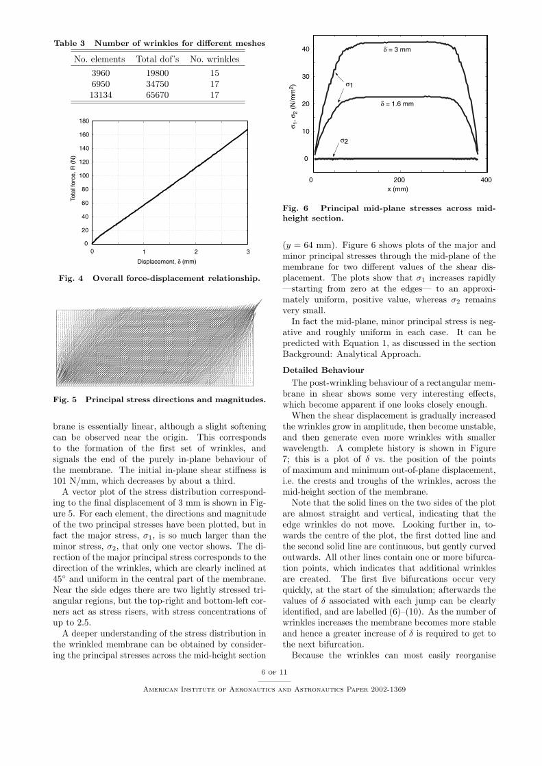
Table 3 Number of wrinkles for different meshes
No. elements Total dof’s No. wrinkles
3960 19800 156950 34750 1713134 65670 17
0 1 2 30
20
40
60
80
100
120
140
160
180
Displacement, δ (mm)
Tota
l for
ce, R
(N
)
Fig. 4 Overall force-displacement relationship.
Fig. 5 Principal stress directions and magnitudes.
brane is essentially linear, although a slight softeningcan be observed near the origin. This correspondsto the formation of the first set of wrinkles, andsignals the end of the purely in-plane behaviour ofthe membrane. The initial in-plane shear stiffness is101 N/mm, which decreases by about a third.A vector plot of the stress distribution correspond-
ing to the final displacement of 3 mm is shown in Fig-ure 5. For each element, the directions and magnitudeof the two principal stresses have been plotted, but infact the major stress, σ1, is so much larger than theminor stress, σ2, that only one vector shows. The di-rection of the major principal stress corresponds to thedirection of the wrinkles, which are clearly inclined at45◦ and uniform in the central part of the membrane.Near the side edges there are two lightly stressed tri-angular regions, but the top-right and bottom-left cor-ners act as stress risers, with stress concentrations ofup to 2.5.A deeper understanding of the stress distribution in
the wrinkled membrane can be obtained by consider-ing the principal stresses across the mid-height section
0 200 400
0
10
20
30
40 δ = 3 mm
δ = 1.6 mm
x (mm)
σ 1, σ
2 (N
/mm
2 )
σ2
σ1
Fig. 6 Principal mid-plane stresses across mid-height section.
(y = 64 mm). Figure 6 shows plots of the major andminor principal stresses through the mid-plane of themembrane for two different values of the shear dis-placement. The plots show that σ1 increases rapidly—starting from zero at the edges— to an approxi-mately uniform, positive value, whereas σ2 remainsvery small.In fact the mid-plane, minor principal stress is neg-
ative and roughly uniform in each case. It can bepredicted with Equation 1, as discussed in the sectionBackground: Analytical Approach.
Detailed Behaviour
The post-wrinkling behaviour of a rectangular mem-brane in shear shows some very interesting effects,which become apparent if one looks closely enough.When the shear displacement is gradually increased
the wrinkles grow in amplitude, then become unstable,and then generate even more wrinkles with smallerwavelength. A complete history is shown in Figure7; this is a plot of δ vs. the position of the pointsof maximum and minimum out-of-plane displacement,i.e. the crests and troughs of the wrinkles, across themid-height section of the membrane.Note that the solid lines on the two sides of the plot
are almost straight and vertical, indicating that theedge wrinkles do not move. Looking further in, to-wards the centre of the plot, the first dotted line andthe second solid line are continuous, but gently curvedoutwards. All other lines contain one or more bifurca-tion points, which indicates that additional wrinklesare created. The first five bifurcations occur veryquickly, at the start of the simulation; afterwards thevalues of δ associated with each jump can be clearlyidentified, and are labelled (6)–(10). As the number ofwrinkles increases the membrane becomes more stableand hence a greater increase of δ is required to get tothe next bifurcation.Because the wrinkles can most easily reorganise
6 of 11
American Institute of Aeronautics and Astronautics Paper 2002-1369

0 200 400
0
1
2
3
x (mm)CrestTroughTransition
(1-5)
(6)(7)
δ (m
m)
(8)
(9)
(10)
Fig. 7 Trajectories of wmax and wmin.
-1
0
1
-1
0
1
0 100 200 300 400
-1
0
1
0 100 200 300 400
(δ = 0.1 mm) (δ = 0.2 mm)
(δ = 1.4 mm) (δ = 2.6 mm)
(δ = 0.6 mm)(δ = 0.5 mm)
Fig. 8 Mid-height cross-sections for different δ’s.
themselves in the middle of the membrane, new wrin-kles tend to appear in this region. The large wrinkleson the sides do not move, as they are “pinned” by thecorner supports.Figure 8 shows different shapes of the mid-height
section of the membrane, as δ is increased. The par-ticular shapes shown here were obtained immediatelyafter the bifurcations labelled (2), (4), (6), (7), (9)and (10) in Figure 7. The number of wrinkles, definedas the number of crests in each plot, is 9, 11, 13, 14,16 and 17 respectively. Note that the wrinkle ampli-tude in the central region increases from 0.13 mm to0.33 mm in these plots, while the wavelength obviouslydecreases.The transition from one shape to the next is not
smooth, but is triggered by a local instability thatleads to mode jumping; this behaviour can also be ob-served in an experiment. The sequence of jumps is seen
0 1 2 30
0.02
0.04
0.06
0.08
0.1
(6)
(7) (8)
(9)
(10)
(1- 5)
−σ2
(N/m
m2 )
Displacement, δ (mm)
Fig. 9 Plot of minor principal stresses, showingevidence of mode jumping.
most clearly in a plot of the minor principal stress, σ2,at a representative point of the membrane vs. the sheardisplacement, as shown in Figure 9. Here the stressesat three points near the centre of the membrane havebeen plotted. Which particular point is chosen is notsignificant, but jumps that are associated with an in-stability that is far away from the chosen point maynot show; therefore, it is useful to monitor the stressat several points. Note that σ2 is always compressive;also note that it would have been pointless to plot themajor principal stress, which is too large for the jumpsto show.Figure 9 clearly shows ten jumps, numbered (1)–
(10). Jump (1) occurred almost immediately afterdisplacing the upper edge. This indicates that thebending stiffness of the membrane is so small thatwrinkles start forming immediately. Due to the ge-ometric imperfections introduced in the membrane,the first jump is directly to a configuration with sevenwrinkles. This is followed in rapid sequence by jumps(2)–(5); then the membrane settles in a more stablestate. It is interesting to note that, as the membranebecomes more stable, σ2 remains almost constant be-tween consecutive jumps.From a numerical simulation viewpoint, it should
be noted that jumps (1)–(6) occur at almost equalstress levels, hence it is likely that secondary bifur-cation paths exist in this region. In some cases itwas found that the solution diverges, then the anal-ysis had to be restarted after increasing the dampingintensity factor to 1× 10⁻⁷. This allowed the analysisto continue, but then the damping intensity had to bedecreased before the next jump. Varying the numeri-cal damping in a simulation has the effect of creating acertain amount of hysteresis, whose effects can be seenby cyclically loading and unloading the membrane.Now, let’s look more carefully into the mode-
jumping. Figure 10 shows an enlarged view of the
7 of 11
American Institute of Aeronautics and Astronautics Paper 2002-1369

0.6 0.62 0.64
0.03
0.032
0.034
0.036
0.038
(a)
(b)
(c)
(d) (e)
(f)
(g)
(h)
−σ2
(N/m
m2 )
Displacement, δ (mm)
Fig. 10 Compressive stress during jump (6).
0.5
0
0.5
0.5
0
0.5
0.5
0
0.5
0 100 200 300 400
0.5
0
0.5
0 100 200 300 400
(a) (b)
(c) (d)
(e)
(g)
(f)
(h)
Fig. 11 Variation of mid-height cross section dur-ing jump (6).
stress-displacement plot near jump (6); eight points—labelled (a)–(h)— have been marked on the equi-librium path and the corresponding mid-height cross-sections are shown in Figure 11.This sequence of cross sections shows that the 13
wrinkles that had formed previously remain stable un-til σ2 has almost reached a peak, at point (c). Herea small asymmetry begins to appear in the cross-sectional plot, which rapidly grows into a new wrinkle(d)–(e). Thus, the transition from 13 to 14 wrinklesoccurs over a very small displacement increment andthen the new mode stabilizes itself while the magni-tude of σ2 rapidly decreases.It is also interesting to investigate the behaviour of
the membrane during a simulated loading–unloadingcycle. Figure 12 shows the variation in the numberof wrinkles when the shear displacement is increasedfrom 0 to 3 mm, and then decreased to 0, and finallyincreased again to 3 mm. Figure 13 shows the cor-responding plot of the stress σ2 at an element in the
0 1 2 30
2
4
6
8
10
12
14
16
18
Num
ber
of w
rinkl
es
First loadingUnloading Reloading
Displacement, δ (mm)
Fig. 12 Number of wrinkles during load cycling.
0 1 2 30
0.02
0.04
0.06
0.08
First loadingUnloading Reloading
−σ2
(N/m
m2 )
Displacement, δ (mm)
Fig. 13 Compressive stress during load cycling.
middle of the membrane. Note that during unloadingthe wrinkles tend to stay on, thus the final number ofwrinkles does not start decreasing until the shear dis-placement has been reduced to δ = 0.8 mm, at whichpoint the number of wrinkles suddenly decreases from17 to 14. Thus, the behaviour on unloading is differ-ent from loading. The stress variation is also muchsmoother during unloading, see Figures 12–13.
During reloading the membrane generally followsthe same path as during first loading, however, the fi-nal configuration with 17 wrinkles is achieved slightlyearlier this time. This may be due to the effect ofthe geometrical imperfections left in the membraneat the end of the first load cycle, which may havefacilitated the formation of the “correct” pattern ofwrinkles. Also note that the stabilisation factor variesduring each simulation, and also during load reversal;it is difficult to quantify the effect of this variation.
8 of 11
American Institute of Aeronautics and Astronautics Paper 2002-1369

0 0.005 0.01 0.015 0.02 0.0254
6
8
10
12
14
16
18
20
Shear angle,
Hal
f-w
avel
engt
h, λ
(m
m)
Eq. 3 ABAQUS
Fig. 14 Comparison of wrinkle wavelengths.
0 0.005 0.01 0.015 0.02 0.0250
0.1
0.2
0.3
0.4
0.5
Shear angle, γ
Am
plitu
de, A
(m
m)
Eq. 4 ABAQUS
Fig. 15 Comparison of wrinkle amplitudes.
Validation of Finite Element ResultsThe results obtained from the ABAQUS simulation
will be compared to the predictions from (i) the ap-proximate analytical model of Wong and Pellegrino[11]
and (ii) a recently published experiment.[19]
Comparison with Analytical Solution
Figures 14 to 16 compare the variation of the wrin-kle half-wavelength and amplitude, and of the minorprincipal stress with the shear angle in a rectangularmembrane with the properties listed in Table 1. Eachfigure shows both an analytically predicted curve, fromEquation 1, 3, and 4, respectively, plus 13 results froman ABAQUS simulation.The wrinkle wavelength and amplitude were ex-
tracted from the ABAQUS output by plotting the mid-height cross section, selecting visually the uniformlywrinkled region, and finally measuring the averagewavelength and amplitude off each plot. The stressvalues were obtained by averaging over the the centralhalf of the cross section.
0 0.005 0.01 0.015 0.02 0.0250
0.02
0.04
0.06
0.08
0.1
Shear angle, γ
−σ2
(N/m
m2 )
Eqs. 1, 3 ABAQUS
Fig. 16 Comparison of mid-plane compressivestresses.
It can been seen that the half-wavelengths λ ob-tained from ABAQUS agree extremely closely with theanalytical predictions made over the whole range of γ.The wrinkle amplitudes are very close for γ < 0.005,but then diverge by up to 0.05 mm although they fol-low similar trends.The variation of the minor principal stress predicted
by ABAQUS also follows the same trend as the ana-lytical model. The two predictions are very close forγ < 0.004. For larger shear angles discrepancies ofup to 30% are observed, particularly for intermediatevalues of γ.
Comparison with an Experiment
The next test of the finite element modelling tech-nique presented in this paper was based on an experi-mental study of a square Mylar foil with side length of228.6 mm, subjected to a combination of tension andshear forces.[19] The experimental setup, shown in Fig-ure 17, consisted of two straight edges (grippers), oneattached to a rigid foundation, the other controlledby two stepper motors. The axial and shear forcesapplied to the membrane, in the x and y-directionsrespectively, are measured by force transducers andmonitored by a computer-controlled system. A capac-itance displacement sensor was used to measure theprofile of the membrane at a distance of 100 mm fromthe stationary gripper.A variety of experiments were conducted, with shear
loads in the range 0–5 N and axial loads in the range1–5 N.[19] The load case chosen to test our simulationconsists of a shear load of 4 N and a tension load of5 N.An ABAQUS model of the membrane was set up,
consisting of 9900 S4R5 shell elements; the gripperswere assumed to be made of Aluminium and modelledwith beam elements, type B21. The beam elementswere connected to the edge of the shell elements usingthe Multi Point Constraint (*MPC, TIE) option in
9 of 11
American Institute of Aeronautics and Astronautics Paper 2002-1369

x
yz
Fig. 17 Experimental set-up.[19]
0 50 100 150 200 250-0.8
-0.6
-0.4
-0.2
0
0.2
0.4
0.6
0.8
y (mm)
z (m
m)
ABAQUSMeasurements
Fig. 18 Comparison between ABAQUS resultsand measurements by Jenkins et al.[19]
ABAQUS. The same loading conditions as in the ex-periment were simulated, by first stretching the mem-brane in the x-direction until the full axial load hadbeen applied and by then applying the shear load as aseparate step while the axial force was kept constant.During the first step, translation in the x-directiononly was allowed, whereas in the second step both xand y-translations of the moving edge were allowed.Figure 18 compares the measured out-of-plane de-
formation for this load case,[19] with the ABAQUSresults.It can be seen that away from the edges the
ABAQUS model predicts the wrinkle wavelength andamplitudes very accurately. Near the edges there is amismatch, mainly because the out-of-plane translationof the free edges had to be restrained in the simula-tion, to avoid singularities, whereas in the experimentthey were left unrestrained. Also, in the experimenta small, unknown prestress had been applied to elim-inate initial wrinkling; in the simulation an arbitraryprestress of 0.25 N was applied, i.e. 5% of the totaltension, during the first stage.A more detailed comparison of experiment and sim-
ulation is presented in Table 4.
Table 4 Comparison of simulation and experiment
Jenkins ABAQUS
No. of wrinkles 8 8Amplitudes (mm) 0.18–0.42 0.23–0.42Half-wavelength (mm) 7.94 10.7Wrinkle angles∗ 35.5◦ 36◦
Discussion and ConclusionsThe finite element simulation technique presented
in this paper has been shown to be robust and ca-pable of producing good quality results. Regardingthe validation that has been presented, a key point tonote is that neither the analytical solution is exact —indeed, it is only a simple approximate solution— northe experimental comparison can be guaranteed to beabsolutely error free. Of the two, the latter is likely tobe the most accurate and, disregarding the differencesassociated with the side edges, the results from theABAQUS simulation in Fig. 18 agree almost perfectly.The detailed implementation of our simulation pro-
cedure is not straightforward but, with the detailsprovided in this paper, it is hoped that anybody suf-ficiently familiar with ABAQUS will be able to repro-duce and extend our results.The potential usefulness of our simulation technique
goes beyond the computation of the wrinkle details.Having been able to “look inside” the membrane andplot —for example— the compressive stress across thewrinkles has provided a convincing backing for theassumption, made in our earlier study,[11] that theaverage principal compressive stress in a uniformlywrinkled membrane is approximately given by Equa-tion 1. Being able to do this sort of thing makes itpossible to identify features of the complex behaviourof thin membranes that need to be included in simplemodels, which can be very useful.
AcknowledgmentsWe thank Professor C.R. Calladine for many use-
ful suggestions. Financial support for Y.W.W. fromthe Cambridge Commonwealth Trust is gratefully ac-knowledged.
References1Wagner, H., “Flat sheet metal girder with very thin metal
web”. Zeitschrift fur Flugtechnik Motorlurftschiffahrt, Vol. 20,1929.
2Reissner, E., “On tension field theory”, Proc. V Interna-tional Congress of Applied Mechanics, pp. 88–92, 1938.
3Mansfield, E.H., “Tension field theory, a new approachwhich shows its duality with inextensional theory”, Proc.XII International Congress of Applied Mechanics, pp. 305–320,1968.
4Mansfield, E.H., The Bending and Stretching of Plates.Cambridge University Press, Cambridge, Second edition, 1989.
∗Maximum wrinkle angles measured from side edge.
10 of 11
American Institute of Aeronautics and Astronautics Paper 2002-1369

5Stein, M. and Hedgepeth, J.M., “Analysis of partly wrin-kled membranes”, NASA TN D-813, 1961.
6Pipkin, A.C., “The relaxed energy density for isotropicelastic membranes”, IMA Journal of Applied Mathematics, Vol.36, pp. 85–99, 1986.
7Steigmann, D.J., “Tension field theory”, Proceedings of theRoyal Society of London, A, Vol. 429, pp. 141–173, 1990.
8Barsotti, R. and Ligaro, S.S., “An accurate wrinkled mem-brane model for analysing the post-critical behaviour of stiff-ened plate-girders”, In Proc. IASS-IACM 2000 ComputationalMethods for Shells and Spatial Structures, (Edited by M. Pa-padrakakis, A. Samartin and E. Onate), pp. 1–16.
9Epstein, M. and Forcinito, M.A., “Anisotropic membranewrinkling: theory and analysis”, International Journal of Solidsand Structures, Vol. 38, pp. 5253–5272, 2001.
10Rimrott, F.P.J. and Cvercko, M., “Wrinkling in thin platesdue to in-plane body forces”, IUTAM Symposium on Inelasticbehaviour of Plates and Shells, Rio De Janeiro, 1985.
11Wong, Y.W. and Pellegrino, S., “Amplitude of wrinklesin thin membrane”. To be published in: New Approaches toStructural Mechanics, Shells and Biological Structures, (Editedby H. Drew and S. Pellegrino), Kluwer Academic Publishers,2002.
12Miller, R.K. and Hedgepeth, J.M., “An algorithm for finiteelement analysis of partly wrinkled membranes”, AIAA Journal,Vol. 20, pp. 1761–1763, 1982.
13Miller, R.K., Hedgepeth, J.M., Weingarten, V.I., Das, P.and Kahyai, S., “Finite element analysis of partly wrinkled mem-branes”, Computers and Structures, Vol. 20, pp. 631–639, 1985.
14Adler, A.L., Mikulas, M.M., and Hedgepeth, J.M., “Staticand dynamic analysis of partially wrinkled membrane struc-tures”. Proc. 41st AIAA/ASME/ASCE/AHS/ASC Structures,Structures Dynamics, and Material Conference and Exhibit, At-lanta, GA, 3-6 April 2000, AIAA-2000-1810.
15Contri, P. and Schrefler, B.A., “A geometrically non-linearfinite element analysis of wrinkled membrane surfaces by ano-compression material model”, Communications in AppliedNumerical Methods, Vol. 4, pp. 5–15, 1988.
16Liu, X, Jenkins, C.H. and Schur, W.W., “Computationalissues in the modelling of wrinkling during parachute deploy-ment”, In IUTAM-IASS Symposium on Deployable Structures:Theory and Applications, (Edited by S. Pellegrino and S.D.Guest), Kluwer Academic Publishers, pp. 239–250, 2000.
17Yang, B., Ding, H., Lou, M. and Fang, H., “A new ap-proach to wrinkling prediction for space membrane structures”,Proc. 42nd AIAA/ASME/ASCE/AHS/ASC Structures, Struc-tural Dynamics, and Materials Conferenceand Exhibit, Seattle,WA, 6-19 April 2001, AIAA-2001-1348.
18Mikulas, M.M., “Behavior of a flat stretched membranewrinkled by the rotation of an attached hub”, NASA TN D-2456, 1964.
19Jenkins, C.H., Haugen, F. and Spicher, W.H., “Experimen-tal measurement to wrinkling in membranes undergoing planardeformation”, Experimental Mechanics, Vol. 38, pp. 147–152,1998.
20Blandino, J.R., Johnston, J.D., Miles, J.J. and Soplop,J.S., “Thin-film membrane wrinkling due to mechanical andthermal loads”, Proc. 42nd AIAA/ASME/ASCE/AHS/ASCStructures, structural Dynamics, and Materials Conference andExhibit, Seattle, WA, 16-19 April 2001, AIAA-2001-1345.
21Hibbit, Karlsson and Sorensen, Inc., ABAQUS Theory andStandard User’s Manual, Version 6.2, Pawtucket, RI, USA,2001.
11 of 11
American Institute of Aeronautics and Astronautics Paper 2002-1369