Embed Size (px)
Citation preview

20/08/14
1
Computer Science 210 Computer Systems 1
Credits: Slides prepared by Gregory T. Byrd, North Carolina State University
Assembly Language
Lecture 12
Problems with Machine Language
• Opcodes are in binary, hard to remember
• Immediate operands, registers are in binary
• DesBnaBons of branches are in binary and must be calculated by hand
• Memory locaBons (variables) are in binary
Problems with Machine Language
• When an instrucBon is inserted or removed, many fields in other instrucBons must be updated
• Easy to get the format of an instrucBon wrong
20/08/14
2
Needed Improvements
• Mnemonic symbols (ADD, BRp) for opcodes
• Mnemonic symbols (count, endwhile) for data variables in memory and desBnaBons of branches
• AutomaBc update of addresses aNer modificaBons to code
Needed Improvements
• Use of decimal or hex numeric literals for immediate operands
• #101, x3A0B
• Simple syntax checking (format of instrucBons, undeclared labels, etc.)
• Reserve memory and iniBalize it
Program Development
Assembler
Linker
Loader
RunBme System
Editor Translate to machine code
Add library code
Place code in appropriate memory locaBons
Execute code
Create source code
/opt/lc3tools/lc3as usage: ./lc3as <ASM filename>

20/08/14
3
An Assembly Language Program ; ; Program to multiply a number by the constant 6 ; Author: John Smith ;
.ORIG x3050 ; Beginning address of code LD R1, SIX LD R2, NUMBER AND R3, R3, #0 ; Clear R3. It will ; contain the product.
; The loop ; AGAIN ADD R3, R3, R2
ADD R1, R1, #-1 ; R1 keeps track of BRp AGAIN ; the iteration.
; HALT
; NUMBER .BLKW 1 ; Data for the program SIX .FILL x0006 ;
.END
LC-‐3 Assembly Language Syntax • Each line of code is
– An instrucBon – An assembler direcBve (or pseudo-‐op) – A comment
• Whitespace is ignored • InstrucBon format:
LABEL OPCODE OPERANDS ; COMMENTS
op#onal mandatory
Opcodes and Operands
• Opcodes are reserved symbols like AND, ADD, etc.
• Operands – Registers: specified by Ri – Numbers: indicated by # (decimal) or x (hex) – Label: symbolic name of memory locaBon
• Separated by a comma

20/08/14
4
Labels and Comments
• Placed at the beginning of a line or included as an operand within an instrucBon
LOOP ADD R1,R1,#-1 BRp LOOP
• A comment begins with ; and extends to the end of that line
Assembler DirecBves
Opcode Operand Meaning .ORIG address starting address of program .END end of program .BLKW n allocate n words of storage
.FILL n allocate one word, initialize with value n
.STRINGZ n-character string
allocate n+1 locations, initialize w/characters and null terminator
Tell the assembler what to do at assembly Bme, start with a dot (.)
Trap Codes Pseudo-‐instrucBons for trap codes:
Code Equivalent Description HALT TRAP x25 Halt execution and print message to
console. IN TRAP x23 Print prompt on console,
read (and echo) one character from keybd. Character stored in R0[7:0].
OUT TRAP x21 Write one character (in R0[7:0]) to console.
GETC TRAP x20 Read one character from keyboard. Character stored in R0[7:0].
PUTS TRAP x22 Write null-terminated string to console. Address of string is in R0.

20/08/14
5
Style Guidelines Use the following style guidelines to improve the readability and understandability of your programs:
• Provide a program header, with author’s name, date, etc., and purpose of program.
• Start labels, opcode, operands, and comments in same column for each line (unless enBre line is a comment).
• Use comments to explain what each register does. • Give explanatory comment for most instrucBons.
Style Guidelines Use the following style guidelines to improve the readability and understandability of your programs: • Use meaningful symbolic names. • Mixed upper and lower case for readability ASCIItoBinary, InputRouBne, SaveR1
• Provide comments between program secBons. • Each line must fit on the page -‐-‐ no wraparounds • Long statements split in aestheBcally pleasing manner
Human-‐Readable Machine Language
Computers like 1s and 0s: 0001001001100001
People like symbols: ADD R1, R1, #1 ; Increment R1
The assembler makes this happen!

20/08/14
6
Example: diff = first - second ;; Author: John Smith ;; This program subtracts the number in the variable SECOND from FIRST ;; and stores the result in DIFF ;; Pseudocode design: ; diff = first - second .ORIG x3000 ;; Register usage: ; R0 = first ; R1 = second ; R2 = diff ; Program code LD R0, FIRST LD R1, SECOND NOT R1, R1 ADD R1, R1, #1 ADD R2, R0, R1 ST R2, DIFF HALT ; Data variables FIRST .BLKW 1 SECOND .BLKW 1 DIFF .BLKW 1 .END
The Assembly Process Convert the program in the source (.asm) file to an executable file (.obj) for the LC-‐3 simulator
First pass: • Scan program file • Find all labels and calculate their addresses, creaBng a symbol table
Second pass: • Convert instrucBons to machine language, using the symbol table
First Pass: Construct the Symbol Table 1. Find the .ORIG statement,
which tells us the address of the first instrucBon. • IniBalize locaBon counter (LC), which keeps track of the
current instrucBon. 2. For each non-‐empty line in the program:
a) If line begins with label, add label and LC to symbol table. b) Increment LC.
– NOTE: If statement is .BLKW or .STRINGZ, increment LC by the number of words allocated.
3. Stop when .END statement is reached. NOTE: A line that contains only a comment is considered an empty line.

20/08/14
7
Example Symbol Table
Code in subtract.asm Table in subtract.sym
LD R0, FIRST LD R1, SECOND NOT R1, R1 ADD R1, R1, #1 ADD R2, R0, R1 ST R2, DIFF HALT FIRST .BLKW 1 SECOND .BLKW 1 DIFF .BLKW 1
// Symbol table // Scope level 0: // Symbol Name Page Address // -‐-‐-‐-‐-‐-‐-‐-‐-‐-‐-‐-‐-‐-‐-‐-‐ -‐-‐-‐-‐-‐-‐-‐-‐-‐-‐-‐-‐ // FIRST 3007 // SECOND 3008 // DIFF 3009
Second Pass: Generate Machine Code
For each executable assembly language statement, generate the corresponding machine language instrucBon
If operand is a label, look up the address from the symbol table
PotenBal errors to detect and flag:
Improper number or type of arguments ex: NOT R1,#7
ADD R1,R2 ADD R3,R3,NUMBER
Immediate argument too large
ex: ADD R1,R2,#1023
Address (associated with label) more than 256 from instrucBon; can’t use PC-‐relaBve addressing mode
Object File Format
An LC-‐3 object file contains • StarBng address (locaBon where program must be loaded)
• followed by…
• Machine language instrucBons

20/08/14
8
MulBple Object Files An object file is not necessarily a complete program.
• system-‐provided library rouBnes • code blocks wriken by mulBple developers
For LC-‐3 simulator, we can load mulBple object files into memory, then start execuBng at a desired address.
• system rouBnes, such as keyboard input, are loaded automaBcally loaded into “system memory,” below x3000
• user code should be loaded between x3000 and xFDFF • each object file includes a starBng address • be careful not to load overlapping object files • In LC-‐3, first file contains the program • Remaining files contain data
The Loader
Loading is the process of copying an executable image into memory
• more sophisBcated loaders are able to relocate images to fit into available memory
• must readjust branch targets, load/store addresses
The Linker Linking is the process of resolving symbols between independent object files • suppose we define a symbol in one module, and want to use it in another
• the notaBon.EXTERNAL, is used to tell assembler that a symbol is defined in another module
• linker will search the symbol tables of other modules to resolve symbols and complete code generaBon before loading

20/08/14
9
CS210 25
Using Branch Instructions
Compute sum of 12 integers. Numbers start at location x3100. Program starts at location x3000.
R1 ← x3100 R3 ← 0
R2 ← 12
R2=0?
R4 ← M[R1] R3 ← R3+R4 R1 ← R1+1 R2 ← R2-1
NO
YES
Sample Program
CS210 26
Address Instruction Comments
x3000 1 1 1 0 0 0 1 0 1 1 1 1 1 1 1 1 R1 ← x3100 (PC+0x0FF)
x3001 0 1 0 1 0 1 1 0 1 1 1 0 0 0 0 0 R3 ← 0
x3002 0 1 0 1 0 1 0 0 1 0 1 0 0 0 0 0 R2 ← 0
x3003 0 0 0 1 0 1 0 0 1 0 1 0 1 1 0 0 R2 ← 12
x3004 0 0 0 0 0 1 0 0 0 0 0 0 0 1 0 1 If Z, goto x300A (PC+5)
x3005 0 1 1 0 1 0 0 0 0 1 0 0 0 0 0 0 Load next value to R4
x3006 0 0 0 1 0 1 1 0 1 1 0 0 0 1 0 0 Add to R3
x3007 0 0 0 1 0 0 1 0 0 1 1 0 0 0 0 1 Increment R1 (pointer)
x3008 0 0 0 1 0 1 0 0 1 0 1 1 1 1 1 1 Decrement R2 (counter)
x3009 0 0 0 0 1 1 1 1 1 1 1 1 1 0 1 0 Goto x3004 (PC-6)
CS210 27
JMP (Register) Jump is an unconditional branch -- always taken.
– Target address is the contents of a register. – Allows any target address.

20/08/14
10
CS210 28
TRAP
Calls a service routine, identified by 8-bit “trap vector.”
When routine is done, PC is set to the instruction following TRAP (We’ll talk about how this works later.)
vector routine
x23 input a character from the keyboard
x21 output a character to the monitor
x25 halt the program
CS210 29
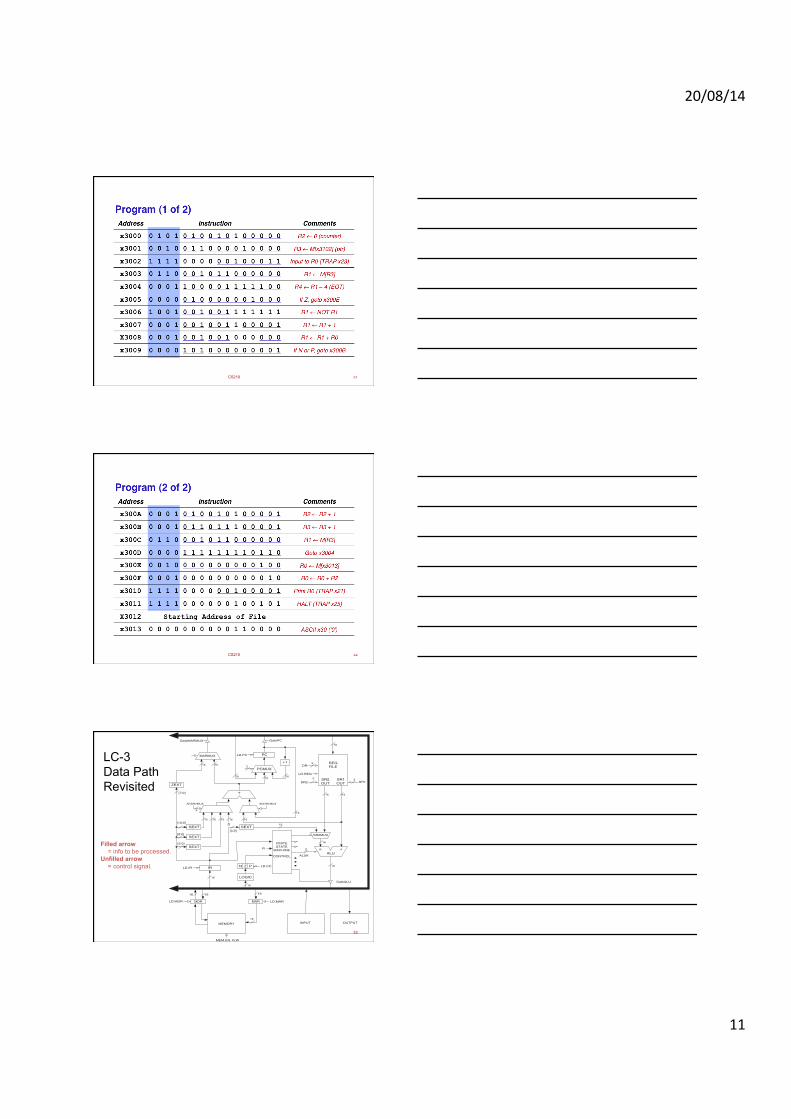
Another Example
Count the occurrences of a character in a file – Program begins at location x3000 – Read character from keyboard – Load each character from a “file”
• File is a sequence of memory locations • Starting address of file is stored in the memory location
immediately after the program
– If file character equals input character, increment counter – End of file is indicated by a special ASCII value: EOT (x04) – At the end, print the number of characters and halt
(assume there will be less than 10 occurrences of the character)
• A special character used to indicate the end of a sequence is often called a sentinel
– Useful when you don’t know ahead of time how many times to execute a loop.
CS210 30
20/08/14
11
CS210 31
CS210 32
33
Filled arrow = info to be processed.
Unfilled arrow = control signal.
LC-3 Data Path Revisited
MDR
MEMORY
MAR
INPUT OUTPUT
16 16 16
16
16
1616
16
SR2MUX
16
16LD.IR
16
1616
16
GateMARMUX
+1
[10:0]
[8:0]
[5:0]
16
16
SEXT
SEXT
SEXT SEXT
MEM.EN, R.W
FINITESTATE
MACHINE
CONTROL
16
16
1616
PC
+
IR
ZEXT
SR2OUT
SR1OUT
REGFILE
[7:0]
2
PCMUX
GatePC
LD.PCMARMUX
ALUK
16 16
163
3 3
2
[4:0]
0
ADDR1MUX
2
ADDR2MUX
SR1SR2
R
LD.REG
DR
LD.MDR
GateALU
ALUAB
LD.MAR
N Z P
LOGIC
LD.CC

20/08/14
12
CS210 34
Data Path Components Global bus
– special set of wires that carry a 16-bit signal to many components
– inputs to the bus are “tri-state devices,” that only place a signal on the bus when they are enabled
– only one (16-bit) signal should be enabled at any time
• control unit decides which signal “drives” the bus
– any number of components can read the bus
• register only captures bus data if it is write-enabled by the control unit
Memory – Control and data registers for
memory and I/O devices – memory: MAR, MDR (also
control signal for read/write)
MDR
MEMORY
MAR
INPUT OUTPUT
16 16 16
16
16
1616
16
SR2MUX
16
16LD.IR
16
1616
16
GateMARMUX
+1
[10:0]
[8:0]
[5:0]
16
16
SEXT
SEXT
SEXT SEXT
MEM.EN, R.W
FINITESTATE
MACHINE
CONTROL
16
16
1616
PC
+
IR
ZEXT
SR2OUT
SR1OUT
REGFILE
[7:0]
2
PCMUX
GatePC
LD.PCMARMUX
ALUK
16 16
163
3 3
2
[4:0]
0
ADDR1MUX
2
ADDR2MUX
SR1SR2
R
LD.REG
DR
LD.MDR
GateALU
ALUAB
LD.MAR
N Z P
LOGIC
LD.CC
5-35
Data Path Components
• ALU – Accepts inputs from register file
and from sign-extended bits from IR (immediate field). – Output goes to bus.
• used by condition code logic, register file, memory
• Register File – Two read addresses (SR1, SR2), one write address (DR) – Input from bus
• result of ALU operation or memory read – Two 16-bit outputs
• used by ALU, PC, memory address • data for store instructions passes through ALU
5-36
Data Path Components
• PC and PCMUX – Three inputs to PC, controlled by PCMUX
1. PC+1 – FETCH stage 2. Address adder – BR, JMP 3. bus – TRAP (discussed later)
• MAR and MARMUX
– Two inputs to MAR, controlled by MARMUX 1. Address adder – LD/ST, LDR/STR 2. Zero-extended IR[7:0] -- TRAP (discussed later)

20/08/14
13
5-37
Data Path Components • Condition Code Logic
– Looks at value on bus and generates N, Z, P signals – Registers set only when control unit enables them
(LD.CC) • only certain instructions set the codes
(ADD, AND, NOT, LD, LDI, LDR, LEA)
• Control Unit – Finite State Machine – On each machine cycle, changes control signals for next
phase of instruction processing
• who drives the bus? (GatePC, GateALU, …) • which registers are write enabled? (LD.IR, LD.REG, …) • which operation should ALU perform? (ALUK) • …
– Logic includes decoder for opcode, etc.

![Servidor SPARC T32 - Oracle · date machinename scsi: [ID 243001 kern.info] smp: smp_do_attach: failed to allocate softstate, device unit-address @w508002000000377f date machinename](https://img.pdfslide.us/doc/110x75/606d389d8bb68b137e280226/servidor-sparc-t32-oracle-date-machinename-scsi-id-243001-kerninfo-smp-smpdoattach.jpg)