Embed Size (px)
Citation preview
1
Compressive characteristics of metal matrix syntactic foams
Imre Norbert ORBULOVa,1, János GINSZTLERa
aResearch Group for Metals Technology of Hungarian Academy of Sciences,
Bertalan Lajos utca 7., 1111, Budapest, Hungary
1Corresponding author
E-mail: [email protected]
Phone: +36 1 463 2386
Fax: +36 1 463 1366
Cell: +36 70 513 9944
Postal address: Research Group for Metals Technology of Hungarian Academy of
Sciences, Bertalan Lajos utca 7., 1111, Budapest, Hungary
Published in: Composites Part A 43 (2012) 553-561,
doi:10.1016/j.compositesa.2012.01.008
Keywords: A: Foams, A: Metal-matrix composites (MMCs), B: Mechanical
properties, B: Strength
2
Abstract
The compressive behaviour of eight different metal matrix syntactic foams (MMSFs)
are investigated and presented. The results showed that the engineering factors as
chemical compositions of the matrix material, the size of the microballoons, the
previously applied heat treatment and the temperature of the compression tests have
significant effects on the compressive properties. The smaller microballoons with
thinner wall ensured higher compressive strength due to their more flawless
microstructure and better mechanical stability. According to the heat treatments, the
T6 treatments were less effective than expected; the parameters of the treatment
should be further optimized. The elevated temperature tests revealed ~30% drop in
the compressive strength. However, the strength remained high enough for structural
applications; therefore MMSFs are good choices for light structural parts working at
elevated or room temperature. The chemical composition – microballoon type – heat
treatment combinations give good potential for tailoring the compressive
characteristics of MMSFs.
Keywords: A. Foams; A. Metal-matrix composites (MMCs); B. Mechanical
properties; B. Strength
1 Introduction
Nowadays metallic foams become more and more important and this is confirmed by
the increasing number of papers published on this topic. The ‘conventional’ metallic
foams, which consist of a metal structure, a gas phase and stabilising particles, have
3
wide spread literature thanks to their potential application possibilities as automotive
parts, energy absorbers etc. or blast and collision damping elements in buildings or
vehicles etc. However there are still existing problems for example in the foaming
process [1, 2]. The metallic foams have a special class, namely the metal matrix
syntactic foams (MMSFs). The MMSFs have numerous perspective applications as
covers, hulls, walls, castings, or in automotive and electromechanical industry sectors
because of their high energy absorbing and damping capability (both blasts and
vibrations) and due to their low density. In the MMSFs the porosity is ensured by the
incorporation of ceramic microballoons [3, 4]. The microballoons are commercially
available and they contain mainly various oxide ceramics [5, 6]. The quality of the
microballoons (uniform wall thickness and flawless wall) has a strong effect on the
mechanical and other properties of the foams.
The MMSFs can be produced by pressure infiltration or by stir casting; both ways are
common in the literature. The main mechanical loading mode of MMSFs is
compression; therefore the compression characteristics have been investigated in
some aspects. Palmer et al. studied the pressure infiltration process and mechanical
behaviour of various microballoon and metal matrix combinations. Compressive
stress-strain data were gathered for foams prepared from combinations of Al1350,
Al5083 and Al6061 alloys for both 45 μm and 270 μm spheres [7]. Balch et al
fabricated aluminium matrix MMSFs by liquid metal infiltration of commercially pure
(cp-Al) and Al7075 aluminium. The cp-Al foam exhibited peak strengths in
compression of over 100 MPa, with a uniform densification plateau of 60% strain.
The Al7075 matrix foams had significantly higher peak strengths (up to 230 MPa)
than cp-Al based ones, up to 230 MPa [8, 9]. Rohatgi et al investigated the pressure
4
infiltration technique of nickel coated and uncoated microballoons. In their other work
loose beds of microballoons (cenospheres) were pressure infiltrated with A356 alloy
melt to fabricate MMSFs. The volume fractions of microballoons in the composites
were in the range of 20–65%, the processing variables included melt temperature,
gas pressure and the size of microballoons. The effect of these processing variables
on the microstructure and compressive properties of the synthesized composites was
characterized [10, 11]. Kiser et al performed investigations on the mechanical
response of a family of MMSFs under both uniaxial compression and constrained die
compression loadings. The key material parameters that varied were the matrix
strength and the ratio of wall thickness to radius of the microballoons. They observed
that the energy absorption capacity was extremely high in comparison with values
that are typical of metal foams [12]. Wu et al established a new method to predict the
compressive strength of MMSFs, showing the relation between the relative wall
thickness of the microballoons and the compressive strength of such foams. The
tests indicated that MMSFs can deform plastically at a relatively higher stress (45-75
MPa); the deformation mechanisms of syntactic foams had also been discussed [13].
Tao et al investigated the mechanical properties of MMSFs with monomodal and
bimodal distribution of microballoons. By combining fine and coarse microballoons,
the density of bimodal MMSFs can be decreased by up to 25%. The bimodal foams
have the advantages of a flat plateau regime, high plateau stress and good ductility.
In next step Al matrix syntactic foams with additional Al particles embedded were
fabricated by pressure infiltration. With the introduction of Al particles, the ductility of
the syntactic foams was significantly increased and the compressive strength also
increased by up to 30% [14, 15]. Zhang et al manufactured aluminium matrix
syntactic foams with low-cost porous ceramic spheres of diameters between 0.25

5
and 4 mm by pressure infiltration casting. The mechanical response of the syntactic
foamsMMSFs with different sphere sizes and densities under static and dynamic
conditions was investigated. They found that the plateau strength and thus the
amount of energy absorption of the syntactic foamMMSFs were largely determined
by the volume fraction of Al and to a lesser extent by the mechanical properties of the
ceramic spheres in the foam [16]. In the works of Mondal et al microballoons in the
range of 30–50 vol% were used as space holders for making syntactic aluminium
foam using stir-casting technique. The synthesized MMSF was characterized in
terms of microstructures, hardness and compressive deformation behaviour. The
compressive deformation behaviour was similar to those of conventional low density
aluminium foam. However, theThey found the plateau stress of these MMSFs is
considerably higher than those of conventional aluminium foams. The dry sliding
wear behaviour of MMSFs has been also studied using a pin-on-disc apparatus [17,
18]. Rabiei and O’Neill produced MMSFs reinforced by hollow steel spheres using
gravity casting techniques. The foam was comprised of steel hollow spheres packed
into a random dense arrangement, with the interstitial space between spheres
infiltrated with a casting aluminium alloy. The aluminium composite foam developed
in the study displayed superior compressive strength and energy absorption capacity
[19]. Ramachandra and Radhakrishna synthesized aluminium based MMSFs
containing up to 15 wt% of microballoons by stir casting method. The properties like
density, hardness, microhardness, ductility and ultimate tensile strength were
investigated. The MMSFs produced was also subjected to corrosion, dry sliding wear
and slurry erosive wear test. The addition of microballoons reduced the density of
composites while increased some of their mechanical properties. The results of wear
studies have shown that the resistance to wear increased with increase in
6
percentage of microballoons [20, 21]. Daoud used different, not aluminium based
matrix materials to produce MMSFs. For example MMSFs with ZnAl22 matrix was
produced by stir casting method. The foam composites containing microballoons
showed superior compressive properties and energy absorption compares to those of
the conventional foams [22]. In the work of Couteau and Dunand aluminium syntactic
foams with densities of 1.2-1.5 g/cm3 were deformed at 500°C under constant
uniaxial compressive stresses ranging from 5 to 14 MPa. The foam’s creep behaviour
was characterized by a short primary stage and a long secondary stage where the
strain rate was constant and minimum, followed by a tertiary stage at high stresses
[23].
The modelling of the MMSFs has been also studied. Bardella and Genna proposed a
complex numerical method to predict the elastic properties of the MMSFs. Explicit
formulae for the homogenized values of the elastic moduli of the MMSFs were
derived [24, 25]. A similar model was used by Marur to compute the effective elastic
moduli of syntactic foams. having perfect adhesion between the inclusion and the
matrix. The computed effective elastic moduli are between the bounds, but usually
overestimate the experimental data. Due to this the assumption of perfect adhesion
between the inclusion and the matrix is relaxed to allow possible localized slip and
separation at the particle interface. The analytical results obtained considering
imperfect interface between microballoons and matrix well agree with the measured
elastic modulus reported in the literature [26, 27]. Sanders and Gibson presented
models for the mechanical properties of foams suggest that closed-cell foams should
have significantly higher modulus and strength than open-cell foams, especially at
low relative densities. The elastic moduli and initial yield strength of MMSFs were

7
analysed too. The results indicated that their theoretical values of moduli and
strength are intermediate to those for open- and closed-cell foams [28].
Most of the MMSFs are produced by pressure infiltration; therefore the infiltration
parameters (like required threshold pressure) have been also studied. Trumble
presented an analysis of spontaneous infiltration of model non-cylindrical pores. The
approach is based on the simple notion that the liquid will penetrate non-cylindrical
pores until the contact angle with the pore surface is established coincident with a flat
liquid surface [29]. Bárczy and Kaptay developed a new infiltration model for “closely
packed equal sphere - CPES” structure. In their study the threshold pressure, the
threshold contact angle and the equilibrium height of penetration has been
determined. All these parameters are significantly different from those, obtained from
the traditional capillary penetration model, but similar to Carman model. The
experiments demonstrated the reliability of the theoretical results [30]. Asthana et al
also overviewed some fundamental materials phenomena relevant to infiltration
processing of metal-matrix composites. They stated that the lack of comprehensive
theoretical framework induce further research efforts to be done [31].
The aim of this paper is to extend the knowledge about MMSFs by analysing and
characterizing new matrix materials, the effect of the microballoon size, the effects of
heat treatment and elevated test temperature.
2 Investigated materials and production methods
Overall eight types of MMSFs were produced by pressure infiltration from the
combination of four matrix materials (Al99.5, AlSi12, AlMgSi1 and AlCu5) and two

8
ceramic microballoons (SL150 and SL300). The chemical compositions of the
matrices are listed in Table 1, in which the approximated ultimate tensile strengths of
the materials in annealed (O) and heat treated (T6) conditions are also presented
only for rough strength comparison. The SL150 and SL300 microballoons were
manufactured and provided by Envirospheres Pty. Ltd. [6]. The main differences
between the two types are in the average diameter, density and wall thickness. Their
main parameters are summarized in Table 2. The MMSFs were produced by
pressure infiltration in a special infiltration chamber (Fig. 1). In the first step the
microballoons were poured into a 360 mm height carbon steel mould to the half and
they were densified by gentle tapping and knocking to get randomly closed pack
structure (RCPS). The cross-section of the mould was 40×60 mm and its inner
surface was coated by a thin graphite layer in order to easier specimen removal. The
maximal volume fraction can be reached with quasi-equal diameter spheres is 64
vol%, as it is published in [32]. After this a layer of alumina mat separator was placed
on the top of the microballoons and a block of matrix material was put on the mat.
The mould was situated into the infiltration chamber, the chamber was closed and the
whole system was evacuated by a vacuum pump (rough vacuum). The proper
heating was ensured by three heating zones and the temperatures of the matrix
block and the microballoons were continuously monitored by two thermocouples.
After the melting of the matrix the molten material formed a liquid cork in the mould
above the separator layer. Tthe vacuum pump was switched off and argon gas was
let into the chamber with a previously set pressure. Due to this a pressure difference
was built up between the inner space of the mould (vacuum under the liquid cork)
and the chamber (argon pressure). This pressure difference forced the molten metal
to infiltrate into the space between the microballoons. After complete solidification the

9
mould was removed from the chamber and water cooled to room temperature. Then
the complete MMSF block (~40×60×180 mm) could be removed from the mould. For
further details about the production process please refer to [4].The blocks were
designated by their constituents: for example Al99.5-SL150 stands for an MMSF
block with Al99.5 matrix and with ~64 vol% SL150 microballoons. The main physical
properties, such as density and porosity are presented in Table 3. The theoretical
densitiesy were calculated by the rule of mixtures (eq. 1).
mmbmbmbt VV 1 (1)
Where Vmb is the volume fraction of the microballoons (64 vol% in every case), ρmb is
the density of the microballoons (from Table 2) and ρm is the density of the matrix
material (from Table 1). The measured densities (ρmeas) were determined by
Archimedes’ method. andThe microballoon-porosity (the porosity in the MMSF
blocks ensured by the hollow microballoons, Pmb) were can be calculated from the
average geometrical parameters of the microballoonsas the original porosity of one
average microballoon (P1mb) multiplied by the volume fraction of the microballoons
(Vmb). The original porosity of one microballoon (P1mb) is its inner volume divided by
its whole volume. Thus
3
3
3
3
43
4
o
imb
o
i
mbmbr
rV
r
r
VP
(2)
Where Vmb is the volume fraction of the microballoons (64 vol% in our case), ri and ro
are the average inner and outer radii of the microballoon respectively (from Table 2).
The matrix porosities porosity (Pm, the volume of the pores in the matrix material, (for
Formázott: Betűtípus: (Alapérték)Arial, 12 pt
Formázott: Tabulátorok: 16 cm,Jobbra zárt
Formázott: Tabulátorok: 16 cm,Jobbra zárt
Formázott: Betűtípus: (Alapérték)Arial, 12 pt
10
example between the microballoons, due to insufficient infiltration) can be calculated
for the whole volume as:
t
meastmP
(3)
divided by the volume of the whole specimen) were calculated as the difference
between theoretical and measured density divided by the theoretical density. The
negative matrix porosity refers to infiltrated microballoons (the microballoon-porosity
should be decreased). The values of matrix porosity are always remained below
7.2%, so the infiltration can be qualified as a suitable one. The total porosity (Pt) is
the sum of the microballoon porosity and the matrix porosity.
3 ExperimentsMeasurements
The main loading mode of foam materials is the compression; therefore compression
tests were performed on cylindrical specimens. The diameter and the height of the
specimens were 14 and 21 mm respectively (H/D=1.5). The compression tests were
performed on a MTS 810 type universal testing machine in a four pillar tool at room
temperature. The surfaces of the tool were grinded and polished. The specimens and
the tool were lubricated with anti-seize material. The test speed was 0.15 mm/s,
which ensured quasi-static compression. Six specimens were compressed until 50%
engineering strain from each MMSF type to get representative results.
Annealed specimens were compressed in the case of all matrix and microballoon
combination (8×6=48 specimens). In the case of heat-treatable matrix materials
(AlMgSi1 and AlCu5) T6 heat treatment was done (according to ASM, see Table 4
Formázott: Betűtípus: (Alapérték)Arial, 12 pt
Formázott: Tabulátorok: 16 cm,Jobbra zárt
11
[33]) and heat treated specimens were also compressed (+4×6=+24 specimen). The
annealed and heat treated results were compared to get information about the effect
of heat treatment. In the case of not heat-treatable matrices (Al99.5 and AlSi12) the
compression tests were performed both at room and elevated temperature (220°C,
above the 0.5 homologous temperature, again +4×6=+24 specimens). The aim of
these tests was to figure out, how the MMSFs would perform as structural elements
at higher temperature.
In summary 96 compression tests were performed and evaluated in accordance with
the ruling standard about the compression tests of cellular materials [34]. This gives
sufficient data for statistical evaluation of the results and trends.
The phase composition of MMSFs was determined by X-ray diffraction
measurements (XRD). For this purpose a Phillips X-Pert type diffractometer with 35
mA cathode heating current and copper anode (CuKα, λ=0.154186 nm) with 40 kV
voltage was used. The rotating speed of goniometer was 0.04 degree/s.
For the investigation of the interface zone between microballoons and the matrix
material line energy dispersive X-ray spectroscopy (line-EDS) was performed by a
Phillips XL-30 type scanning electron microscope equipped with an EDAX Genesis
EDS analyser. The excitation voltage was 20 kV, one hundred points were measured
along the lines, each point was excited for 20 s with 35 µs detector acquisition rate.
4 Results and discussion
The load bearing capacity of MMSFs depends on many parameters, such as the
chemical composition of the matrix, the type of the microballoons, the test
Formázott: Betűtípus: 12 pt
Formázott: Betűtípus: 14 pt
12
temperature or the previous heat treatments. In order to characterize these effects
we have done numerous compression tests as described in the previous section.
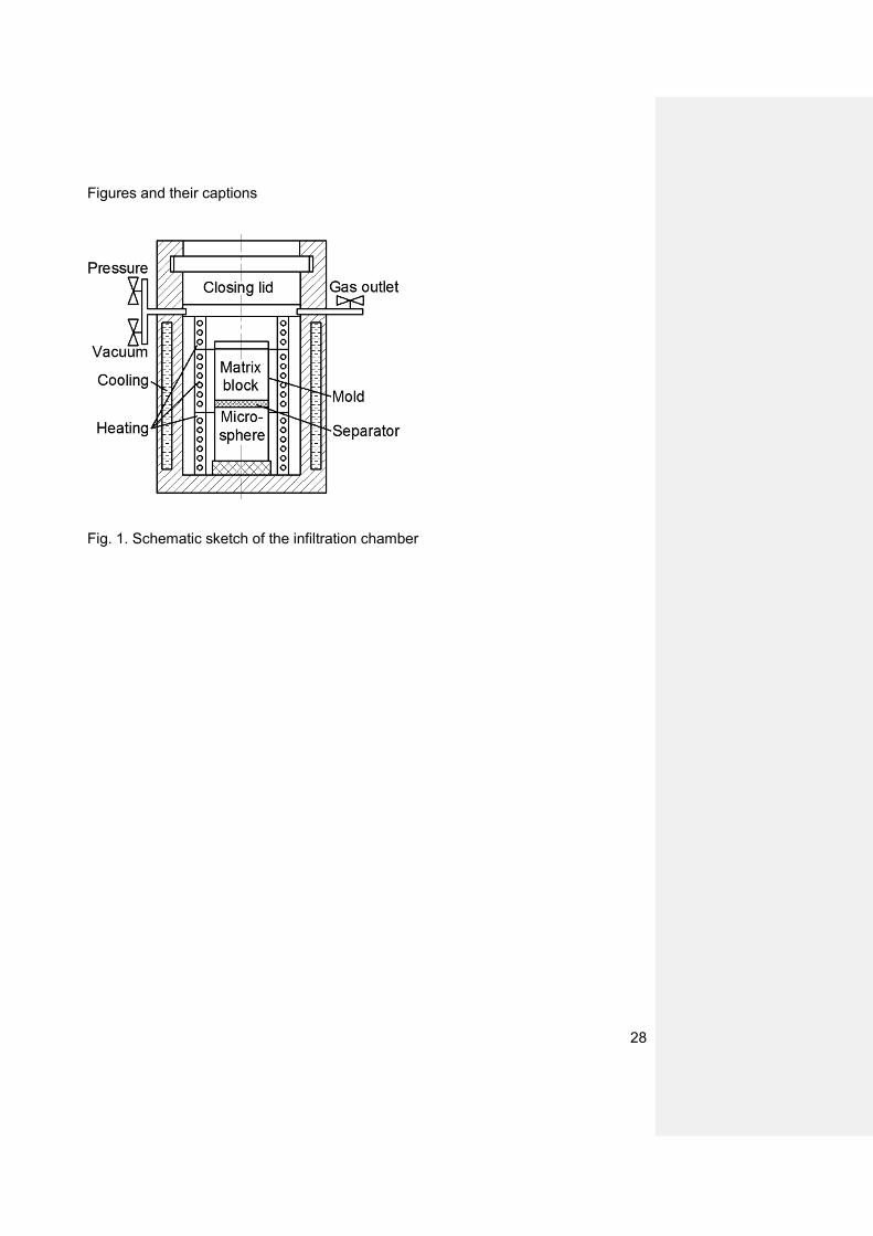
During the tests the engineering stress – engineering deformation curves were
plotted like in Fig. 2. As an example Fig. 2 shows the graph for an AlMgSi1-SL150
MMSF specimen tested at room temperature and in annealed condition. Gupta et al
[35] and Bunn and Mottram [36] have investigated polymer matrix syntactic foams
with similar stress – strain diagrams. According to the results of Gupta et al the
general stress – strain curves were divided into three parts [35]. Based on their idea
the diagram of MMSFs can be divided into three main parts containing overall five
sections. In the first section (from point A to B) the specimens were deformed
elastically only. In this section the microballoons remained unharmed as it can be
observed in Fig. 2a and 2b; there are no cracks at all. The overall deformation is
related to the elastic deformation of the composite. The slope of the first part is
defined as structural stiffness (S (MPa), see [34] about the standardized compression
test of cellular materials). The stiffness is one of the characterizing properties of the
MMSFs. In the vicinity of point A the deviation from the fitted dashed line can be
caused by the internal sliding of the material or by the springs and the natural
movement of the sliding parts of the tool. Due to this it should be distracted from the
measured strain. In the second section from point B to C the plastic deformation of
the matrix began. The load transfer between the matrix and the microballoons
increased to its maximum, but the microspheres remained still unharmed. At the end
of this section at point C the stress reached the compressive strength (σc (MPa)) at
the fracture strain (εc (%)). These parameters are also important characterizing
properties, because they show the load bearing capacity of the MMSFs directly. At
point C the first crack appeared in the specimen. This first rupture was very thin and
13
very sharp and only one row of the microballoons was cracked as it is shown in Fig.
2c. The plane of the crack closed ~45° with the horizontal direction, because in the
case of uniaxial loading the maximum shear load appears in this direction. The stress
suddenly dropped to point D due to the reduced load bearing capacity caused by the
fracture of the microballoons and the movement of the recently formed specimen
halves. From point D to E the fracture band expanded and the crack became thicker.
The neighbouring microballoons broke and the load bearing capacity decreased
further, but more slowly due to the friction between the specimen halves (Fig. 2d).
This deformation phenomenon consumed significant strain and mechanical energy
due to the fracture of the ceramic microballoons and due to the plastic deformation of
the matrix. The absorbed mechanical energy is the fourth main characterizing
parameter of the MMSFs, as it indicates the damping and protecting capability of the
MMSFs against a blast, collision or simple vibration. The absorbed energy is equal to
the area under the recorded stress-strain curve and can be integrated numerically.
From point E the complete densification of the specimens took place. At the end of
this process the cavities of the broken microballoons were filled up by the matrix
material due to its plastic deformation (Fig. 2e). This part – also called plateau region
– absorbs lot of energy, because it is relatively long and has high stress value. The
shape of the diagrams after point E can be ascending or constant (usually ascending
because the densifying material needs higher force to be deformed). It may contain
larger drops or local maximums due to secondary cracks. The process ended at 50%
engineering strain when the test stopped (point F in Fig. 2). One of the compressed
specimens was grinded to its half diameter and shown in Fig. 3a. The fracture band
appeared under ~45° as it is expected from the maximum shear stress theory,
mentioned above. One can observe the shear band was rather wide and very well

14
defined. However the remaining part of the specimen was unharmed and this part
would be able to absorb further energy if the compression was continued. In Fig. 3b a
magnified picture about the sharp margin between the densified and unharmed
region is shown. In summary the structural stiffness, compressive strength, fracture
strain and the area under the whole curve – which gives the total absorbed energy
(W (J/m3)) during the test – is used to characterize the compressive behaviour of the
MMSFs. Therefore the effect of the chemical composition of the matrix material, the
effect of the applied microballoons and the influence of the heat treatment and test
temperature on the characterizing properties mentioned above were investigated,
pursued and detailed in the next paragraphs. The averages of the measured
properties and their scatterings are listed in Table 5, in the following sections the
trends of the effects are shown by average graphs for better understanding and for
cleaner presentation.
4.1 The effect of the chemical composition of the matrix and the influence of
the type of microballoons
During the compression tests in annealed condition and at room temperature the
MMSFs with Al99.5 matrix showed the smallest strength. The lack of alloying caused
low strength, high fracture strain, low structural stiffness and in overall: more plastic
behaviour (see Fig. 4). The AlCu5 matrix SFs proved to be the strongest and showed
the highest compressive strength compared to the Al99.5 matrix SFs (+37 % and +47
% in the case of SL150 and SL300 microballoons, respectively) due to the existing
solid-solution strengthening mechanism. Beside the highest strength the AlCu5
matrix SFs have the highest structural stiffness and the lowest fracture strain;

15
therefore they behaved the most rigid way. This can be also traced on their graphs
containing numerous smaller drops in the plateau region, suggesting that many
smaller cracks appeared during the compression. The next strongest were AlMgSi12
and AlSi12 with almost the same strength. In the case of AlMgSi1 alloy the hardening
effect was similar to the Cu alloying (solid-solution strengthening) and caused some
increment in the strength (+11 % and +16 % compared to Al99.5-SL150 and Al99.5-
SL300 respectively), but not as much as the more effective Cu. The AlMgSi1 based
MMSFs showed almost as rigid behaviour as the AlCu5 matrix SFs and because of
their lower compressive and plateau strength they absorbed significantly lower
mechanical energy (about -13% in the case of both microballoon types). In the case
of Si alloying the increment was caused by the relatively high amount of Si alloying,
however the result became almost the same as in the case of AlMgSi1 matrix (+7 %
and +14 % compared to Al99.5-SL150 and Al99.5-SL300 respectively). This proved
that pure Si alloying is not as much effective than Mg and Si alloying together. This
main difference between the two strengthening mechanisms was also confirmed by
the fracture strain. In the case of AlMgSi1 matrix the fracture strain was small due to
the stronger strengthening mechanism, while in the case of AlSi12 larger fracture
strain was recorded, despite the higher amount of alloying elements. In summary the
compressive strength followed the trend that is shown by the UTS of the matrix
materials (see Table 1). The matrix has decisive effect on the compressive properties
of the MMSFs, but not as significant as in the case of pure metals: the changes were
much more moderate (compare the differences in Tables 1 and 5). The fracture strain
was inversely proportional; it was decreased if the compressive strength increased.
The structural stiffness varied in accordance to the strength and strain: if the strength
was high and the strain was low the stiffness became higher. The absorbed

16
mechanical energy varied between wide ranges due to the different shapes of the
plateau region (between point E and F in Fig. 2.) corresponding to the different
fracture histories. Therefore it is hard to tell any thumb rule about its trend but in
general the higher compressive strength resulted in higher plateau strength and
higher absorbed energy. According to the results detailed above, the application of
alloyed matrix is justified and gives the advantage to tailor the compressive
properties of the MMSFs. It is worth to mention here that the ceramic microballoons
with proper coating could be used as a source of alloying elements in MMSF
systems. The appropriate choice and concentration of alloying element in the surface
coating of the microballoons can enhance the properties of the MMSFs economically.
The type of the microballoons influenced the compressive strength, the fracture strain
and the structural stiffness only. Compared to the larger SL300 type, the smaller
SL150 type microballoons gave higher compressive strength (+3-10 %), lower
fracture strain (-4-20 %) and usually higher structural stiffness (+5-25 %, except in
the case of AlCu5 matrix: -5 %). As it is shown in Table 2 the SL150 microballoons
are significantly smaller and they also have thinner wall. The smaller diameter and
higher curvature give higher compressive strength and mechanical stability to the
microballoons. Moreover, smaller wall thickness ensures lower probability for
deflections (see Fig. 5a); therefore the small SL150 microballoons have higher
strength than the larger, SL300 type microballoons with thicker walls and more
defects (see Fig. 5b.).
17
4.2 The effect of heat treatment
In the case of heat treatable aluminium alloys the T6 treatment ensures much higher
strength compared to the annealed condition. This would be very useful in the case
of MMSFs too, because stronger MMSFs can absorb higher amount of mechanical
energy and they can be more effective as collision dampers or vehicle hulls. The
recorded diagrams are shown in Fig. 6a and 6b. The T6 heat treatment caused ~10
% and ~15 % higher compressive strength in the case of AlMgSi1 and AlCu5 matrix
respectively, which is significantly less than expected. This could be caused by some
chemical reactions between the microballoons and matrix materials, detailed in
another papers [8, 9, 37]. For example the liquid aluminium can reduce the SiO2
content of the microballoons, the exchange reaction is:
4Al(liq)+3SiO2(sol)→2Al2O3(sol)+3Si(sol), (4)
aAs a result the wall of the microballoon was damaged and pure Si is dissolved and
precipitated into the matrix material (the maximal solubility of Si in Al is ~1,5 wt% at
~577 °C [38]). This phenomenon was confirmed by the results of XRD
measurements (Table 6). From Table 6 the presence of the above mentioned
chemical exchange reaction is clear. The amorphous SiO2 content was reduced and
Al2O3 was formed as α-Al2O3 os as γ-Al2O3, while Si was dissolved and precipitated
in the matrix material. This diffusion reaction is induced by the Si concentration
mismatch between the material of microballoons and the matrix. However, the
reaction has not taken place in the case of AlSi12 matrix, because its high Si content.
This small example shows that these reactions can seriously modify the chemical
composition of the matrix, and therefore the applied T6 heat treatment parameters
were not the best, they should be further optimized (about the interfacial reactions in
Formázott: Tabulátorok: 16 cm,Jobbra zárt
Formázott: Nem Felső index/ Alsóindex
18
details refer to our previous paper [37]). The interfacial reaction also confirmed by
line-EDS measurements. For example the results of AlMgSi1-SL150 MMSF are
shown in Fig. 7. The BSE image on the left shows a part of a microballoon (right side
in the image). The measuring line was perpendicular to the outer surface of the
microballoon. Near to the microballoon’s surface (for example in the vicinity of point
A) Si precipitations can be observed. The graph on the right in Fig. 7 shows the
chemical element composition along the measured line. Between point B and C a
relatively wide 2-4 µm zone can be observed, within this zone the Al and the O
content changed smoothly (about the interfacial reactions in details refer to our
previous paper [37]). As the strength increased the fracture strain and the structural
stiffness also increased a little bit (less than +5 % in all cases). Due to the higher
fracture strain, the MMSFs became more ductile, the first crack appears later and this
can be useful in numerous applications. Beside the strengthening mechanism due to
heat treatment the dissolved and precipitated Si particles also have effect on the
mechanical properties, mainly on the stiffness.
Considering microballoon size Tthe SL300 microballoons performed less again,
exactly as it is detailed in the previous section.
4.3 The effect of elevated temperature
In Fig. 7 8 the diagrams of Al99.5 and AlSi12 MMSFs compressed at room and at
elevated (220°C) temperature are shown and compared. Due to the elevated
temperature the compressive strength dropped by ~30-35 % in the case of all
matrices and microballoon types. The formability increased significantly and due to
19
this dual effect the transformed strength between the matrix and the microballoons
increased slower than at room temperature and the first fracture appeared only later.
In one word: the fracture strain increased by ~5-10 % in all cases. The MMSFs
became more ductile, but they remained strong enough and can be applied as
structural elements: the compressive strengths were still above 120 MPa. This
capability at elevated temperature is a serious advantage compared to the
conventional metal and polymer foams and makes the MMSFs good choice for
structural parts in the neighbourhood of combustion engines or other heat producing
systems. The absorbed energies were also decreased, due to the lower compressive
strength induced lower plateau strength.
The effect of the microballoons’ type was the same at elevated temperature too. The
MMSFs with SL300 type microballoons showed ~5% lower compressive strength.
5 Conclusions
From the results of the above mentioned and discussed measurements the following
conclusions can be drawn:
The typical compression diagram of the MMSFs can be divided into three main
parts containing five sections. The peak strength (compressive strength), its
strain (fracture strain), the structural stiffness and the area below the graph
(the absorbed mechanical energy) can be applied as characterizing values of
the compressive behaviour.
The smaller, SL150 type microballoons ensured higher compressive strength,
higher fracture strain and higher structural stiffness than the larger SL300

20
microballoons in any circumstances. Beside the higher curvature and therefore
higher compressive strength, the thinner wall of the smaller microballoons
contains fewer defects, than the thicker wall of the larger ones. The difference
between the properties of MMSFs with SL150 and SL300 microballoons is
about 5-10%.
The T6 heat treatment of AlMgSi1 and AlCu5 matrix syntactic foams was
successful, but the strength increment was much smaller than expected (~5-
10% instead of 50-100%). This could be caused by chemical reactions
between the constituents, which modified the composition of the matrix and
therefore the applied temperature parameters during T6 treatment were not
the best and they should be optimized.
The increased test temperature caused ~30% drop in the compressive
strength, while the fracture strain increased by ~10%. The structural stiffness
decreased, thus the MMSF was more ductile than at room temperature. The
decrease of compressive strength is significant, but not too large; therefore the
MMSFs can be applied as structural elements at elevated temperatures.
In summary the compressive properties of MMSFs can be tailored by proper
selection of the materials and by careful design for individual and unique
applications.
Acknowledgements
The Metal Matrix Composites Laboratory is supported by Grant # GVOP 3.2.1-2004-
04-0145/3.0. This paper was supported by the János Bolyai Research Scholarship of
21
the Hungarian Academy of Sciences. The investigations were supported by The
Hungarian Research Fund, NKTH-OTKA PD 83687. This work is connected to the
scientific program of the " Development of quality-oriented and harmonized R+D+I
strategy and functional model at BME" project. This project is supported by the New
Széchenyi Plan (Project ID: TÁMOP-4.2.1/B-09/1/KMR-2010-0002). Thanks to C. H.
Erbslöh Hungaria Ltd. and R. Tóth for providing the E-spheres.
References
[1] Babcsan N, Leitlmeier D, Banhart J. Metal foams—high temperature colloidsPart
I. Ex situ analysis of metal foams. Colloids and Surfaces A: Physicochemical and
Engineering Aspects. 2005;261(1-3):123-30.
[2] Babcsán N, Moreno FG, Banhart J. Metal foams—High temperature colloidsPart
II: In situ analysis of metal foams. Colloids and Surfaces A: Physicochemical and
Engineering Aspects. 2007;309(1-3):254-63.
[3] Erikson R. A survey of current technology. 5th Aerospace Materials. Von Braun
Center, Huntsville, Alabama2002.
[4] Orbulov IN, Dobránszky J. Producing metal matrix syntactic foams by pressure
infiltration. Periodica Polytechnica Mechanical Engineering. 2008;52(1):35-42.
[5] Sphere Services Inc, http://wwwsphereservicescom/, last accessed: 25th March
2011.
[6] Envirospheres Ltd, http://wwwenvirospherescom/productsasp, last accessed: 28th
November 2011.
22
[7] Palmer R, Gao K, Doan T, Green L, Cavallaro G. Pressure infiltrated syntactic
foams—Process development and mechanical properties. Materials Science and
Engineering: A. 2007;464(1-2):85-92.
[8] Balch D, Odwyer J, Davis G, Cady C, Grayiii G, Dunand D. Plasticity and damage
in aluminum syntactic foams deformed under dynamic and quasi-static conditions.
Materials Science and Engineering A. 2005;391(1-2):408-17.
[9] Balch D, Dunand D. Load partitioning in aluminum syntactic foams containing
ceramic microspheres. Acta Materialia. 2006;54(6):1501-11.
[10] Rohatgi PK, Guo RQ, Iksan H, Borchelt EJ, Asthana R. Pressure infiltration
technique for synthesis of aluminum–fly ash particulate composite. Materials Science
and Engineering A. 1998;244:22-30.
[11] Rohatgi P, Kim J, Gupta N, Alaraj S, Daoud A. Compressive characteristics of
A356/fly ash cenosphere composites synthesized by pressure infiltration technique.
Composites Part A: Applied Science and Manufacturing. 2006;37(3):430-7.
[12] Kiser M, He MY, Zok FW. The mechanical response of ceramic microballoon
reinforced aluminum matrix composites under compressive loading. Acta Materialia.
1999;47(9):2685-94.
[13] Wu G, Dou Z, Sun D, Jiang L, Ding B, He B. Compression behaviors of
cenosphere–pure aluminum syntactic foams. Scripta Materialia. 2007;56(3):221-4.
[14] Tao XF, Zhang LP, Zhao YY. Al matrix syntactic foam fabricated with bimodal
ceramic microspheres. Materials & Design. 2009;30(7):2732-6.
[15] Tao XF, Zhao YY. Compressive behavior of Al matrix syntactic foams toughened
with Al particles. Scripta Materialia. 2009;61(5):461-4.

23
[16] Zhang LP, Zhao YY. Mechanical Response of Al Matrix Syntactic Foams
Produced by Pressure Infiltration Casting. Journal of Composite Materials.
2007;41(17):2105-17.
[17] Mondal DP, Das S, Ramakrishnan N, Uday Bhasker K. Cenosphere filled
aluminum syntactic foam made through stir-casting technique. Composites Part A:
Applied Science and Manufacturing. 2009;40(3):279-88.
[18] Mondal DP, Das S, Jha N. Dry sliding wear behaviour of aluminum syntactic
foam. Materials & Design. 2009;30(7):2563-8.
[19] Rabiei A, Oneill A. A study on processing of a composite metal foam via casting.
Materials Science and Engineering: A. 2005;404(1-2):159-64.
[20] Ramachandra M, Radhakrishna K. Synthesis-microstructure-mechanical
properties-wear and corrosion behavior of an Al-Si (12%)—Flyash metal matrix
composite. Journal of Materials Science. 2005;40(22):5989-97.
[21] Ramachandra M, Radhakrishna K. Effect of reinforcement of flyash on sliding
wear, slurry erosive wear and corrosive behavior of aluminium matrix composite.
Wear. 2007;262(11-12):1450-62.
[22] Daoud A. Synthesis and characterization of novel ZnAl22 syntactic foam
composites via casting. Materials Science and Engineering: A. 2008;488(1-2):281-95.
[23] Couteau O, Dunand D. Creep of aluminum syntactic foams. Materials Science
and Engineering: A. 2008;488(1-2):573-9.
[24] Bardella L, Genna F. Elastic design of syntactic foamed sandwiches obtained by
filling of three-dimensional sandwich-fabric panels. International Journal of solids and
Structures. 2001;38:307-33.
[25] Bardella L, Genna F. On the elastic behavior of syntactic foams. International
Journal of solids and Structures. 2001;38:7235-60.
24
[26] Marur P. Effective elastic moduli of syntactic foams. Materials Letters.
2005;59(14-15):1954-7.
[27] Marur PR. Influence of imperfect interface on the elastic moduli of syntactic
foams. Computational Materials Science. 2009;46(2):327-32.
[28] Sanders WS, Gibson LJ. 2003-Mechanics of hollow sphere foams. Materials
Science and Engineering A. 2003;347:70-85.
[29] Trumble KP. Spontaneous infiltration of non-cylindrical porosity Close packed
spheres. Acta Materialia. 1998;46(7):2363-7.
[30] Bárczy T, Kaptay G. Modelling the infiltration of liquid metals unto porous
ceramics. Materials Science Forum. 2005;473-474:297-302.
[31] Asthana R, Rohatgi PK, Tewari N. Infiltration processing of metal - matrix
composites: a review. Processing of Advanced MAterials. 1992;2:1-17.
[32] Jaeger HM, Nagel SR. Physics of the granular state. Science. 1992;5051:1523-
31.
[33] ASM Handbook Volume 4, Heat Treating, Third printing, ASM International,
1995, p 1861-1960.
[34] Testing of metallic materials - Compression test of metallic cellular materials,
DIN50134 standard, October 2008.
[35] Gupta N, Kishore, Woldesenbet E, Sankaran S. Studies on compressive failure
features in syntactic foam material. Journal of Materials Science. 2001;36:4485-91.
[36] Bunn P, Mottram JT. Manufacture and compression properties of syntactic
foams. Composites. 1993;24(7):565-71.
[37] Orbulov IN, Dobranszky J, Nemeth A. Microstructural characterisation of
syntactic foams. Journal of Materials Science. 2009;44(15):4013-9.

25
[38] Binary Alloys Phase Diagrams, Second Edition, ASM International, 1990, p 211-
213.
26
Table captions
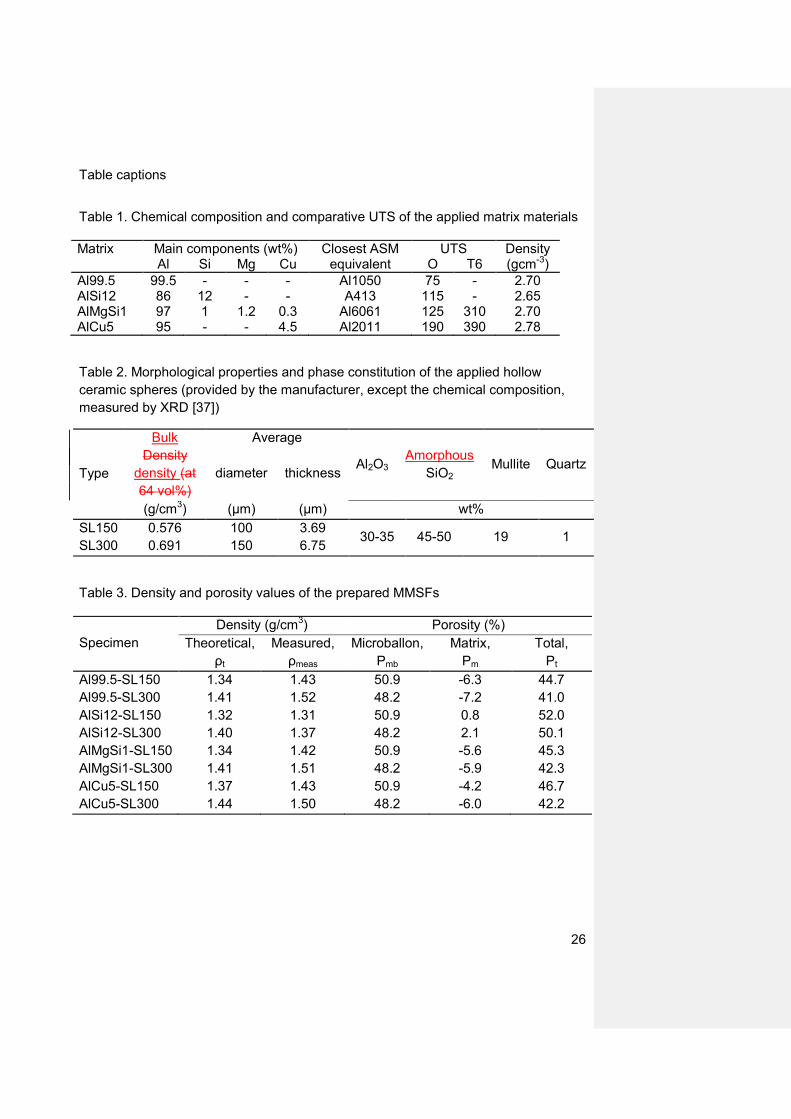
Table 1. Chemical composition and comparative UTS of the applied matrix materials
Matrix Main components (wt%) Closest ASM equivalent
UTS Density Al Si Mg Cu O T6 (gcm-3)
Al99.5 99.5 - - - Al1050 75 - 2.70 AlSi12 86 12 - - A413 115 - 2.65 AlMgSi1 97 1 1.2 0.3 Al6061 125 310 2.70 AlCu5 95 - - 4.5 Al2011 190 390 2.78
Table 2. Morphological properties and phase constitution of the applied hollow
ceramic spheres (provided by the manufacturer, except the chemical composition,
measured by XRD [37])
Type
Bulk
Density
density (at
64 vol%)
Average
Al2O3 Amorphous
SiO2 Mullite Quartz
diameter thickness
(g/cm3) (μm) (μm) wt%
SL150 0.576 100 3.69 30-35 45-50 19 1
SL300 0.691 150 6.75
Table 3. Density and porosity values of the prepared MMSFs
Specimen
Density (g/cm3) Porosity (%)
Theoretical,
ρt
Measured,
ρmeas
Microballon,
Pmb
Matrix,
Pm
Total,
Pt
Al99.5-SL150 1.34 1.43 50.9 -6.3 44.7
Al99.5-SL300 1.41 1.52 48.2 -7.2 41.0
AlSi12-SL150 1.32 1.31 50.9 0.8 52.0
AlSi12-SL300 1.40 1.37 48.2 2.1 50.1
AlMgSi1-SL150 1.34 1.42 50.9 -5.6 45.3
AlMgSi1-SL300 1.41 1.51 48.2 -5.9 42.3
AlCu5-SL150 1.37 1.43 50.9 -4.2 46.7
AlCu5-SL300 1.44 1.50 48.2 -6.0 42.2
27
Table 4. Parameters of the applied T6 heat treatments
Matrix Solution treatment Cooling
medium Aging
temperature (˚C) time (h) temperature (˚C) time (h)
AlMgSi1 520 1 water 170 14 AlCu5 500 1 water 160 14
Table 5. Properties of the investigated MMSFs
Designation
Compressive
strength
Fracture
strain
Structural
stiffness
Absorbed
energy
(MPa) (%) (MPa) (J/m3)
Al99.5-SL150-O-20 169±6.5 6.83±0.099 29.6±0.56 3765±50.7
Al99.5-SL300-O-20 154±1.7 6.57±0.219 23.9±0.06 4681±80.6
AlSi12-SL150-O-20 181±6.7 6.60±0.318 28.4±0.21 5805±75.3
AlSi12-SL300-O-20 176±3.1 6.45±0.054 22.1±0.48 3226±110.8
AlMgSi1-SL150-O-20 187±5.9 3.65±0.195 67.8±2.92 5132±133.7
AlMgSi1-SL300-O-20 179±3.3 3.05±0.104 63.9±3.95 3461±132.8
AlCu5-SL150-O-20 232±0.3 3.20±0.078 82.3±0.21 5761±122.6
AlCu5-SL300-O-20 227±3.9 3.00±0.222 86.3±3.33 4776±119.1
AlMgSi1-SL150-T6-20 199±2.4 4.13±0.322 71.3±1.91 3861±113.7
AlMgSi1-SL300-T6-20 184±6.2 3.62±0.234 64.0±0.95 3521±149.7
AlCu5-SL150-T6-20 248±7.9 3.25±0.225 85.3±2.68 5587±129.5
AlCu5-SL300-T6-20 244±5.9 3.15±0.189 88.3±1.76 6380±133.6
Al99.5-SL150-O-220 127±6.8 7.30±0.212 21.8±0.84 4320±77.9
Al99.5-SL300-O-220 123±4.4 6.60±0.297 22.4±0.36 4316±26.1
AlSi12-SL150-O-220 136±1.6 7.03±0.161 21.5±0.40 3439±73.6
AlSi12-SL300-O-220 130±7.8 7.12±0.520 21.3±0.77 2766±78.8
Table 6. Phase constitution of MMSFs according to XRD measurements (wt%)
Specimen Al Si Mullite α-Al2O3 γ-Al2O3 Amorphous
SiO2
CuAl2
Al99.5-SL150 67 8 11 3 11 0 -
Al99.5-SL300 70 7 11 2 10 0 -
AlSi12-SL150 72 7 13 0 0 8 -
AlSi12-SL300 72 7 12 0 0 9 -
AlMgSi1-SL150 60 7 8 0 25 0 -
AlMgSi1-SL300 60 6 6 0 28 0 -
AlCu5-SL150 60 6 8 8 12 0 6
AlCu5-SL300 60 5 10 7 12 0 6
28
Figures and their captions
Fig. 1. Schematic sketch of the infiltration chamber
29
Fig. 2. Typical compressive diagram of AlMgSi1-SL150 MMSF specimen and the
broken specimen (bottom right corner)
30
Fig. 3. Grinded specimen after compressed to 50% engineering strain showing wide
shear band (between dashed lines) (a) and magnified optical microscopy image
about the margin between the densified and unharmed regions (b)
31
Fig. 4. The effect of the matrix material and microballoon type on the (a) compressive
strength, (b) fracture strain and (c) structural stiffness of MMSFs in annealed
condition
32
Fig. 5. Representative optical microscopic images about AlSi12 matrix SFs
containing (a) SL150 type microballoons with very thin and flawless walls and (b)
SL300 type microballoons with thicker wall and many defects (arrows)

33
Fig. 6. The effect of heat treatment on the (a) compressive strength, (b) fracture
strain and (c) structural stiffness of MMSFs (O = annealed, T6 = T6 heat treated).

34
Fig. 7. BSE image and EDS line-scan profiles of the AlMgSi-SL150 syntactic foam Formázott: Balra zárt
35
Fig. 78. The effect of test temperature on the (a) compressive strength, (b) fracture
strain and (c) structural stiffness of MMSFs


![arXiv.org e-Print archive - Modelling hollow thermoplastic ...and revealing an extremely lightweight alternative to other syntactic foams (i.e., [6]). 3.5. Poisson’s ratio Fig. 5(a)](https://img.pdfslide.us/doc/110x75/607ba1dae63b441ecf7fcba6/arxivorg-e-print-archive-modelling-hollow-thermoplastic-and-revealing-an.jpg)