Embed Size (px)
Citation preview

COMPRESSION TUBE FITTINGS


TABLE OF CONTENTS
All Rotarex compression tube fittings are produced in Europe in accordance with international standards (ISO; CGA..) and are guaranteed to provide safe and reliable performance in operation. All locations are ISO 9001.
Certificate
R-110
PRODUCT RANGE OVERVIEW P.004
TECHNOLOGY OVERVIEW P.006
SELECTING THE RIGHT FITTING P.008
- Materials P.008
- Thread & End Connections P.009
- Visual Identification P.010
- Cleaning & Packaging P.011
- Ordering Codes & Options P.011
- Tube Selection Guide P.012
PRODUCTS P.014
- Straight Unions P.014
- Elbow Unions P.028
- Tee & Cross Unions P.035
- Adaptors P.042
- Chromatograph Fittings P.053
- Components & Accessories P.055
ASSEMBLY GUIDELINES P.062
REFERENCE CHARTS P.064
- Gas Compatibility Table P.064
- Conversion Guide P.065
ASTMF
1387

4 PRODUCT RANGE OVERVIEW
ALL RIGHTS OF CHANGE RESERVED
STRAIGHT UNIONS
US P. 014Straight union
USMOD P. 014 Conversion union
URS P. 015Reducing union
UCS P. 015Bulkhead union
UMS AN P. 021Straight union «AN»
UCMS AN P. 021 Bulkhead union «AN»
UMOMS P. 022Male O-ring connector
UMOMSS P. 022Male O-ring connector «UN»
UMS NPT / BSPT / BSPP G / BSPP K / METRIC / THERMOCOUPLE CONNECTOR P. 016Male union
UCMS NPT / BSPT P. 020Male bulkhead union
UCOMS NPT / BSPT P. 020Male bulkhead union with O-ring
UFS NPT / BSPT / BSPP P. 023Female union
UCFS NPT / BSPT / BSPP P. 026Female bulkhead union
UMSWS P. 027Tube socket weld union
UMBWS P. 027Male pipe weld connector
TEE & CROSS UNIONS
TS P. 035Union tee
TRS P. 036Reducing tee
TRS P. 036Reducing run tee
TMS NPT / BSPT P. 037Male branch tee
TMRS NPT / BSPT P. 038Male run tee
TFS NPT / BSPT / BSPP P. 039Female branch tee
TFRS NPT / BSPT / BSPP P. 040Female run tee
CS P. 041Cross
ELBOW UNIONS
EQS P. 028Elbow
EQM45S P. 028 45° male elbow
EQMS NPT / BSPT / BSPP P. 029 Male elbow
EQFS NPT / BSPT / BSPP P. 031Female elbow
EQSWS P. 034Socket weld elbow
EQBWS P. 034Male pipe weld elbow

5PRODUCT RANGE OVERVIEW
ALL RIGHTS OF CHANGE RESERVED
CHROMATOGRAPH FITTINGS
USFVM P. 053Straight union - low dead volume
TSFVM P. 053Union tee - low dead volume
UMSFVM P. 053Male connector - low dead volume
URSFVM P. 054Column end reducing union - low dead volume
URSZVM P. 054Column end reducing union - zero dead volume
UFSFVM P. 054Column end female connector - low dead volume
EDS P. 054Male nut
ADAPTORS
APS P. 042Port connector
APRS P. 042Reducing port connector
ADRS P. 043Reducer
ADTS P. 043Heat exchanger reducer
UCAS P. 044Bulkhead reducer
AMOD P. 044Converting reducer
ADS NPT / BSPT / BSPP G / BSPP K P. 045Male adaptor
ADS AN P. 048Male adaptor «AN»
AOMSS P. 048Male O-ring adaptor «UN»
AOMS P. 049Male O-ring adaptor «NPSM»
AFS NPT / BSPT / BSPP P. 050Female adaptor
AFS AN P. 052Female adaptor
PRE-ASSEMBLY P. 058
TOOLGASKETS P. 059 TUBE BENDER P. 060 DEBURRING P. 060
TOOLTUBE CUTTER P. 060 PTFE TAPE P. 060
COMPONENTS & ACCESSORIES
BPS P. 055Cap
OBS P. 055Plug
FF P. 056Front ferrule
BF P. 056Back ferrule
SET P. 056Ferrule set (10 of each)
ES P. 057Nut
EMS P. 057Knurled nut
ECS P. 057Bulkhead locknut
INS P. 058Insert for plastic tube
CCS P. 058Gauge

6
ALL RIGHTS OF CHANGE RESERVED
INTRODUCTION
ROTAREX COMPRESSION TUBE FITTINGS TECHNOLOGY
BEST PRACTICE:
For best results minimize the use of threaded connections in your instal-lation. Compression fittings have a higher pressure rating, are quicker and easier to install and are much more resistant to vibration.
Rotarex double-ring compression tube fitting technology combines leak-free confidence and strength with maximum ease and flexibility… and is the recommended technology for all instrumentation applications maxi-mizing safety, control and productivity.
Rotarex offers one of the largest selections of fittings in the industry – and specializes in non-standard dimensions with over 100 unique configura-tions not available from other supplies, and a choice of over 12 material types representing the cutting edge alloy technologies.
Rotarex ferrules utilize an advanced design geometry where the ferrule force-displacement vectors are optimized to deliver an exceptionally efficient double-grip compression into the tube’s outer surface when tightened.
Exceptionally precise machining tolerances ensures a leak-tight grip around the entire tube circumference.
All Rotarex stainless steel alloy back ferrules are hardened by a low temper-ature carburization process that significantly increases surface hardness,
increases compression strength and improves resistance to wear and gall-ing. This back ferrule differential hardness is essential to tightly grip into the tube and provide a robust leak-tight compression seal.
Reusable: The Rotarex compression tube fitting is re-usable several times, making possible configuration changes and quicker servicing of the system.
Fitting body
Front ferrule
Nut
Back ferrule
Tightening the nut exerts radial compression around the tube in two places creating an excep-tional grip – able to withstand very high working pressure – and vibration.
Easy to install: just insert the tube and tighten
TECHNOLOGY OVERVIEW

7
ALL RIGHTS OF CHANGE RESERVED
INTRODUCTION
INTERCHANGEABILITY
Rotarex compression tube fittings are designed and certified interchang-able with double-ferrule components from other leading manufacturers. That means superior choice, flexibility and productivity for your operations.
DESIGNED FOR BETTER OPERATING RESULTS
SAFETY: - Leak-tight confidence - Exceptional tube grip - Gaugeable to ensure proper tightness - Stays tight even with vibration - High temperature resistant
CONTROL: - A vast range of sizes and shapes enables your optimal installation configuration
PRODUCTIVITY: - Fast & Easy to install - Long lasting and reusable - Quicker maintenance
GAUGEABILITY
Rotarex compression tube fittings allow installers to verify the proper tightness using a gap inspection gauge – for greater safety and leak-free confidence.
When properly tightened, the gauge should not be able to fit between the body and shoulder of the nut.
The inspection gauge is only to be used on the first assembly.
TRACEABILITY
Each stainless steel component is compliant with high and ultra-high purity traceability requirements, and most stringent applications such as automotive. For greater quality assurance, a material-specific identification
code is visible on every component in addition to the Rotarex 3-star quality assurance symbol.
Properly tightened, the gauge will not fit
New material coding system (from September 2011)
3-star quality assurance symbol on forged bodies
Not tight enough if the gauge fits
Former material coding system(before September 2011)
3-star quality assurance symbol on hex flats and nuts
BEST PRACTICE:
Although you can intermix components, it is strongly recommended to use exclusively Rotarex components throughout your entire gas installation. Rotarex fittings are designed and manufactured to the same demanding specifications as our leading valves and regula-tors for maximum warrantied performance. Certified by TüV Rheinland – a leading independent 3rd party testing
& certification facility based in Germany.
TECHNOLOGY OVERVIEW (CONTINUED)

8
ALL RIGHTS OF CHANGE RESERVED
INTRODUCTION
O-RINGS
STANDARD MATERIALS
All Rotarex compression fittings are standardly available in stainless steel 316L and raw brass, covering most major application needs. In addition, ten other speciality alloy materials are available upon request for specific applications. Which material is best for your installation?
Stainless steel 316L: The recommended option for corrosive gases and high purity applications due to its superior resistance, non-reactivity, exceptional durability and high-surface finish properties. It is compatible with most gas types and low-velocity oxygen applications.
Rotarex uses stainless steel type 316L, an austentic chromium nickel stainless steel containing Molybdenum. It offers:
- Exceptional corrosion resistance - particularly against sulfuric, hydrochloric, acetic, formic and tartaric acids, acid sulfates and alkaline chlorides;
- resistance to pitting from chloride-ion solutions; and - outstanding strength even at elevated temperatures
Raw brass: The most commonly used material for industrial and high velocity oxygen applications due to its cost effectiveness versus stainless steel, good strength, resistence and low-friction flow properties.
All raw brass fittings can be chrome plated on request (see page 11).
Materials compliant with enforcable norms
Status Fitting MaterialRotarex
codeBar stock Forging
Standard Brass L ASTM B16, ASTM B453
ASTM B124
Standard Stainless steel 316L I ASTM A276, ASME SA 479, EN 1.4404
ASTM A182, ASME SA182, EN 1.4404
Upon request Stainless steel 904L WASTM A182, EN 1.4539
ASTM A182
Upon requestSuper duplex stainless steel 2507
SD ASTM A479 ASTM A182
Upon request Alloy 400 M ASTM B164 ASTM B564
Upon request Alloy 600 O ASTM B166 ASTM B564
Upon request Alloy 625 Q ASTM B446 ASTM B564
Upon request Alloy 825 Y ASTM B425 ASTM B564
Upon request Alloy C-276 H ASTM B574 ASTM B564
Upon request Steel C ASTM A108 -
Upon request Alloy 20 R ASTM B473 ASTM B462, ASTM B472
Upon request Titanium T ASTM B348 ASTM B381
Need more information? One of our material engineers would be happy to discuss the pros and cons of each option to help you choose the best solution.
Gas Compatibility: make sure the body material is compatible with the gas type you will be using. Consult the gas compatibility reference chart on page 64.
Rotarex O-ring fittings with elastomer sealing technology are delivered with the O-ring specification as per the below chart. Special cleaning of the parts in the manufacturing process might modify the performances. Other materials are available upon request.
Rotarex Fittings in Stainless Steel 316L with O-rings, for connections up to 25 mm and 1 inch, are to be used up to 206 bars or 3000 psi.
UNIFORM DASH NUMBERING,
ACCORDING TO AEROSPACE STANDARD AS568B
Straight thread type (inch) NBR FPM
5⁄16"-24 -011 -902
3⁄8"-24 -012 -903
7⁄16"-20 -013 -904
½"-20 -112 -905
9⁄16"-18 -113 -906
¾"-16 -116 -908
1 1⁄16"-12 -121 -912
TYPE DESIGNATION TEMPERATURE RATING HARDNESS
Nitrile rubber NBR -30 to 100°C -22 to 212°F 79 (± 5)
Fluorocarbon rubber* FPM -28 to 204°C -18 to 400°F 78 (± 5)
Ethylene propylene rubber EPDM -50 to 140°C
-58 to 284°F 83 (± 5)
*Fluorocarbon rubber designation: - FPM is the international abbreviation according to DIN/ISO - FKM is the short form for the fluoroelastomer category to ASTM.
SELECTING THE RIGHT FITTING
9
ALL RIGHTS OF CHANGE RESERVED
INTRODUCTION
To apply, wrap the tape clockwise starting from under the first thread to avoid potential contact between the PTFE and the gas.
THREADS AND END CONNECTIONS
Rotarex offers a complete range of thread options compliant with world-wide norms & standards. Please ask us if you do not see what you require.
Family thread configurationRotarex thread
identifcation code
DescriptionInternational standards
for threads and end connections
NPT-BSPTTapered Pipe Thread
N
National Pipe Tapered thread (NPT)
- Seal is made on the thread. - Thread angle 60°- Thread sealant is required.
ASME B1.20.1(part1)
ASME B1.20.1(part2)
T
British Standard Pipe Tapered thread (BSPT) (Whitworth Conical)
- Seal is made on the thread. - Thread angle 55°- Thread sealant is required.
ISO 7/1
EN 10226-1/2
DIN 3852-2, Form C
BSPP Parallel Pipe Thread
K
British Standard Pipe Parallel thread (BSPP)(Whitworth Cylindrical)
- Must be used with the sealing gasket according to DIN 3852-2, form A. Used with a GBS gasket (sealing gasket sold separately).
ISO 228/1
DIN 3852-2 Form A
JIS B0202
G
British Standard Pipe Parallel thread (BSPP)(Whitworth Cylindrical)
- Seals with a sealing gasket according to DIN 3852-2, form B. Used with a GCU gasket (sealing gasket sold separately).
ISO 228/1
BS 2779
JIS B0202
DIN 3852-2 Form B
G
British Standard Pipe Parallel thread (BSPP)(Whitworth Cylindrical)
- Seals with a sealing gasket according to DIN 3852-2, form B. Used with a GKF or GTE gasket (sealing gasket sold separately).
- Compatible with all BSPP male threads.- Flat bottom for manometer connection
ISO 228/1
BS 2779
JIS B0202
EN 837-1 & EN 837-3
Unified Screw thread
UNUnified Screw Thread (UN)
- Straight thread with a groove for an-O-ring (included)ASME B1.1
AN37
Army and Navy application (AN)
- Seals on the tapered face- Tube must be flared to 37°, according to SAE standard
ASME B1.1
SAE J514
NPSM
National Pipe Straight Mechanical (NPSM)
- American Standard for straight pipe threads- Straight thread with a groove for an O-ring (included)
ASME B1.20.1
Metric Thread MB
Metric Parallel Thread
- Seals using a sealing gasket to DIN 3852-1, form B. - Used with a GCU gasket (sealing gasket sold separately).
DIN13
ISO 261
DIN 3852-1 Form B
Sealants - When assembling tapered pipe thread, it is mandatory to use pipe thread sealant. This will ensure a leak free seal, as well as prevent thread galling.
- Rotarex recommends using PTFE tape due to its ease of application (see page 60 for PTFE tape).
SELECTING THE RIGHT FITTING (CONTINUED)

10
ALL RIGHTS OF CHANGE RESERVED
INTRODUCTION
NPT Thread NPT Thread
Male Threads Female Threads
Metric compression tube fittings (mm)
BSPT Thread BSPT Thread BSPP ThreadFractional compression tube fittings (inch)
Small shoulder No shoulder
Chamfer No Chamfer Flat Small shoulder Small groove
SELECTING THE RIGHT FITTING (CONTINUED)
FOR NPT AND BSPT(ISO 7/1) TAPERED PIPE THREADS:
Pressure ratings change according to thread size, thread type (male or female thread) and material type. Be certain to use the right threads for your application.
The chart on the right represents the pressures rates for male and female threads in Brass and SS 316L.
Pressure ratings are based on the ASME code for pressure piping B31.3, process piping at ambient temperature
MAXIMUM ALLOWABLE STRESS (PRESSURE)
BRASS STAINLESS STEEL 316L
Thread Size Male Female Male Female
1⁄16" bar 379 227 717 434
psi 5500 3300 10400 6300
1⁄8" bar 345 221 648 420
psi 5000 3200 9400 6100
¼" bar 276 200 517 427
psi 4000 3000 7500 6200
3⁄8" bar 269 179 503 345
psi 3900 2600 7300 5000
½" bar 262 165 496 317
psi 3800 2400 7200 4600
¾" bar 248 159 469 296
psi 3600 2300 6800 4300
1" bar 179 152 345 283
psi 2600 2200 5000 4100
to determine the pressure in Mpa, multiply bar value by 0.10
Visual Differences of Metric vs. Fractional Fittings: Components for metric tube dimensions have visible shoulders. Fractional dimension fittings do not.
Visual Differences between NPT and BSPT threads:Male NPT end connections have a chamfer at the inside diameter. Female BSPT end connections have a small shoulder on the outside face and BSPP G connections have a groove on the outside face.
Allowable stress values are based on the standard ASME B31.3 (ambient temperature)
Material bar psi
Stainless Steel 316L 1378 20000
Brass 689 10000
FOR SAE STRAIGHT THREADS :
Pressure ratings are based on connector SAE J1926. Depending on the ref-erence, Rotarex fittings with SAE threads might have lower pressure rates.
bar psi
5⁄16-24 315 4568
7⁄16-20 315 4568
½-20 315 4568
9⁄16-18 315 4568
¾-16 315 4568
7⁄8-14 250 3626
1 1⁄16-12 250 3626
1 3⁄16-12 200 2900
1 5⁄16-12 200 2900
Female thread pressure ratings are lower than those for male threads of the same diameter. Take the lower female thread ratings into account when choosing thread dimensions.
FOR NPT AND BSPT(ISO 7/1) TAPERED PIPE THREADS:

A
D P
H
D2
E2E
A
D P
H
E
*Specify material when ordering. See page 8 for materials and codes.
CONVERSION UNION | USMOD
STRAIGHT UNION | US
14
ALL RIGHTS OF CHANGE RESERVED
STRAIGHT UNIONS 15
ALL RIGHTS OF CHANGE RESERVED
STRAIGHT UNIONS
*Specify material when ordering. See page 8 for materials and codes.
APPLICATION
Join a metric tube to a fractional tube.
Special requirements on request
APPLICATION
Connects tubes of the same dimension in a straight configuration.
Special requirements on request
TUBE SIZE - FRACTIONAL (inch)
D Reference A E H (mm) P
1⁄16” US*1⁄16 0.99 0.34 8 3⁄64”
1⁄8” US* 1⁄8 1.39 0.54 12 3⁄32”
3⁄16” US* 3⁄16 1.47 0.60 12 1⁄8”
¼” US* ¼ 1.61 0.64 14 3⁄16”
5⁄16” US* 5⁄16 1.70 0.68 14 ¼”
3⁄8” US* 3⁄8 1.77 0.90 17 9⁄32”
½” US* ½ 2.02 0.96 22 1 3⁄32”
5⁄8” US* 5⁄8 2.05 0.96 24 ½”
¾” US* ¾ 2.11 0.96 37 5⁄8”
7⁄8” US* 7⁄8 2.17 1.02 30 ¾”
1” US* 1” 2.56 1.23 36 7⁄8”
TUBE SIZE-METRIC TO FRACTIONAL (mm to inch)
D D2 Reference A E E2 H P
3 1⁄8” USMOD* 3 1⁄8 35.2 12.9 12.8 12 2.4
4 1⁄8” USMOD* 4 1⁄8 36.5 13.7 12.8 12 2.4
4 3⁄16” USMOD* 4 3⁄16 38.6 13.7 13.7 12 2.4
4 ¼” USMOD* 4 ¼ 39.4 13.7 15.3 14 2.4
6 1⁄8” USMOD* 6 1⁄8 38.5 15.3 12.8 14 2.4
6 3⁄16” USMOD* 6 3⁄16 39.8 15.3 13.7 14 3.2
6 ¼” USMOD* 6 ¼ 41.0 15.3 15.3 14 4.8
6 5⁄16” USMOD* 6 5⁄16 42.3 15.3 16.2 14 4.8
6 3⁄8” USMOD* 6 3⁄8 43.7 15.3 17.2 17 4.8
8 ¼” USMOD* 8 ¼ 42.3 16.2 15.3 14 6.4
8 5⁄16” USMOD* 8 5⁄16 43.2 16.2 16.2 14 6.4
8 3⁄8” USMOD* 8 3⁄8 44.3 16.2 16.9 17 6.4
D D2 Reference A E E2 H P
10 1⁄8” USMOD*10 1⁄8 41.8 17.2 12.8 17 2.4
10 ¼” USMOD*10 ¼ 44.5 17.2 15.3 17 4.8
10 5⁄16” USMOD*10 5⁄16 45.1 17.2 16.2 17 6.4
10 3⁄8” USMOD* 10 3⁄8 45.9 17.2 17.2 17 7.1
12 ¼” USMOD* 12 ¼ 47.3 22.8 15.3 22 4.8
12 3⁄8” USMOD* 12 3⁄8 48.4 22.8 16.9 22 7.1
12 ½” USMOD* 12 ½ 51.2 22.8 22.8 22 9.5
16 5⁄8” USMOD* 16 5⁄8 52 24.4 24.4 24 12.7
18 ¾” USMOD* 18 ¾ 53.5 24.4 24.4 27 15.1
20 ½” USMOD* 20 ½ 55 26 22.8 30 10.3
25 1” USMOD* 25 1 65 31.3 31.3 36 21.8
TUBE SIZE - METRIC (mm)
D Reference A E H P
3 US*3 35,3 12,9 12 2,4
4 US*4 37,3 13,7 12 3,2
6 US*6 41,0 15,3 14 4,8
8 US*8 43,2 16,2 14 6,4
10 US*10 46,2 17,2 17 7,9
12 US*12 51,2 22,8 22 9,5
14 US*14 52,0 24,4 24 11,1
16 US*16 52,0 24,4 24 12,7
18 US*18 53,5 24,4 27 15.1
20 US*20 55,0 26,0 30 15,9
22 US*22 55,0 26,0 30 18.3
25 US*25 65,0 31,3 36 22,2
A
D d
E e
H
P
REDUCING UNION | URS
APPLICATION
Connects tubes of different dimensions.
Special requirements on request
TUBE SIZE - METRIC (mm)
D d Reference A E e H P
4 3 URS* 4 3 36,6 13,7 12,9 12 2,4
6 3 URS* 6 3 38,6 15,7 12,9 14 2,4
6 4 URS* 6 4 39,4 15,7 13,7 14 3,2
8 6 URS* 8 6 42,3 16,2 15,3 14 4,8
10 6 URS* 10 6 44,5 17,2 15,3 17 4,8
10 8 URS* 10 8 45,1 17,2 16,2 17 6,4
12 6 URS* 12 6 47,0 22,8 15,3 22 4,8
12 8 URS* 12 8 47.8 22.8 16.2 22 6.4
12 10 URS* 12 10 48,7 22,8 17,2 22 7.9
16 10 URS* 16 10 49,5 24,4 17,2 24 7.9
16 12 URS* 16 12 52,0 24,4 22,8 24 9,5
18 12 URS* 18 12 53.5 24.4 22.8 27 9.5
20 12 URS* 20 12 54,0 26,0 22,8 30 9,5
22 20 URS* 22 20 55,6 26,0 26,0 30 15,9
25 20 URS* 25 20 62,3 31,3 26,0 36 15,9
25 22 URS* 25 22 62,3 31,3 26,0 36 19,1
TUBE SIZE - FRACTIONAL (inch)
D d Reference A E e H (mm) P
1⁄8” 1⁄16” URS* 1⁄8 1⁄16 1.22 0.50 0.34 12 3⁄64”
3⁄16” 1⁄8” URS* 3⁄16 1⁄8 1.44 0.54 0.51 12 3⁄32”
¼” 1⁄16” URS* ¼ 1⁄16 1.35 0.60 0.34 14 3⁄64”
¼” 1⁄8” URS* ¼ 1⁄8 1.52 0.62 0.51 14 3⁄32”
¼” 3⁄16” URS* ¼ 3⁄16 1.55 0.62 0.54 14 1⁄8”
5⁄16” ¼” URS* 5⁄16 ¼ 1.67 0.64 0.60 14 3⁄16”
3⁄8” ¼” URS* 3⁄8 ¼ 1.75 0.68 0.60 17 3⁄16”
3⁄8” 5⁄16” URS* 3⁄8 5⁄16 1.78 0.68 0.64 17 ¼”
½” ¼” URS* ½ ¼ 1.85 0.90 0.60 17 3⁄16”
½” 3⁄8” URS* ½ 3⁄8 1.92 0.90 0.68 17 9⁄32”
5⁄8” 3⁄8” URS* 5⁄8 3⁄8 1.95 0.96 0.68 24 9⁄32”
5⁄8” ½” URS* 5⁄8 ½ 2.05 0.96 0.90 24 13⁄32”
¾” ½” URS* ¾ ½ 2.13 1.02 0.90 30 3⁄8”
¾” 5⁄8” URS* ¾ 5⁄8 2.13 1.02 0.96 30 ½”
1” ½” URS* 1" ½ 2.38 1.23 0.9 36 3⁄8”
1” ¾” URS* 1’’ ¾ 2.45 1.23 0.96 36 5⁄8”
Hex flats (H) are metric. Fractional upon request*Specify material when ordering. See page 8 for materials and codes.
Hex flats (H) are metric. Fractional upon request*Specify material when ordering. See page 8 for materials and codes.
Hex flats (H) are metric. Fractional upon request*Specify material when ordering. See page 8 for materials and codes.
A
H
E
P D
TUBE SIZE - METRIC (mm)
D Reference A E H PB’Head Hole
Drill SizeMA. B’Head
Thick.
3 UCS* 3 51,3 12,9 12 2,4 8,3 12,7
4 UCS* 4 53,6 13,7 14 3,2 9,8 12,7
6 UCS* 6 57,7 15,3 17 4,8 11,5 10,3
8 UCS* 8 61,0 16,2 17 6,4 13,1 11,1
10 UCS* 10 63,7 17,2 19 7,9 16,3 11,1
12 UCS* 12 71,0 22,8 24 9,5 19,5 12,7
14 UCS* 14 72,5 24,4 27 11,1 21,0 12,7
16 UCS* 16 72,5 24,4 27 12,7 22,5 12,7
18 UCS* 18 78,9 24,4 30 15,1 26,0 16,7
20 UCS* 20 84,5 26,0 36 15,9 29,0 19,1
22 UCS* 22 84,9 26,0 36 19,1 29,0 20,6
25 UCS* 25 95,8 31,3 41 22,2 33,8 23,8
BULKHEAD UNION | UCS
APPLICATION
Join tubes of the same dimension through a wall panel.
Special requirements on request
TUBE SIZE - FRACTIONAL (inch)
D Reference A E H (mm) PB’Head Hole
Drill SizeMA. B’Head
Thick.
1⁄8” UCS* 1⁄8 2.02 0.51 12 3⁄32” 21⁄64” ½”
3⁄16” UCS* 3⁄16 2.11 0.54 14 1⁄8” 25⁄64” ½”
¼” UCS* ¼ 2.27 0.60 17 3⁄16” 29⁄64” 17⁄32”
5⁄16” UCS* 5⁄16 2.40 0.64 17 ¼” 33⁄64” 9⁄16”
3⁄8” UCS* 3⁄8 2.45 0.68 19 9⁄32” 37⁄64” 9⁄16”
½” UCS* ½ 2.80 0.90 24 13⁄32” 49⁄64” 19⁄32”
5⁄8” UCS* 5⁄8 2.85 0.96 27 ½” 57⁄64” 19⁄32”
¾” UCS* ¾ 3.11 0.96 27 5⁄8” 1 1⁄64” 25⁄32”
1” UCS* 1’’ 3.77 1.23 41 7⁄8” 1 21⁄64” 15⁄16”
Hex flats (H) are metric. Fractional upon request*Specify material when ordering. See page 8 for materials and codes.
*Specify material when ordering. See page 8 for materials and codes.
*Specify material when ordering. See page 8 for materials and codes.
11
ALL RIGHTS OF CHANGE RESERVED
INTRODUCTION
SELECTING THE RIGHT FITTING (CONTINUED)
For further information, please refer to Rotarex Cleaning Standard STQ/01 on our web site: www.rotarex.com
CLEANING AND PACKAGING
To maintain the proper purity of the fluid system, every Rotarex fitting is thoroughly cleaned of oil and metal particles from the machining process.
For special applications where higher purity is warranted, Rotarex offers the following additional cleaning and packaging options:
- individual packaging: fittings can be delivered individually packaged to maintain extra purity during transport and storage. For ordering, please add PKG at the end of the reference
(example : USI 6 PKG)
- For oxygen systems, Rotarex offers a specific cleaning to meet the stringent international safety standards for oxygen applications. For more information, please refer to Rotarex Special Cleaning and Packag-ing STQ/02 For ordering, please add DO at the end of the reference
(example : USI 6 DO)
- For Absolute Cleaning (all parts are lubricant free), please refer to Rotarex Special Cleaning and Packaging STQ/02 For ordering, please add DA at the end of the reference
(example : USI 6 DA)
Example: To order a fitting oxygen clean in an individual packaging, mention as following: USI 6 DO PKG
CHROME PLATING
All Rotarex raw brass fittings are available in chrome plated brass as an option: For ordering: please add CHR at the end of the reference
(example: USI 6 CHR)
ORDERING CODES & OPTIONS
Rotarex makes it easy to choose the exact material, diameter, thread size and thread type to meet your specific needs. Each product page has a configuration table where you can quickly find the available dimensions, thread types and the corresponding reference number. Where you see an asterisk (*), you will need to specify the material. See page 8 for avail-able materials and codes.
Example: Product number: UCMS I 6 ¼ N
Don’t see what you want? We can custom-manufacture any product to your exact specifications. Just ask one of our engineers.
Need help choosing the optimal solution? One of our engineers will be happy to discuss your project in more detail and help you choose the best solution.
www.rotarex.com

OK for all fluid services using pre-assembly tool
12
ALL RIGHTS OF CHANGE RESERVED
INTRODUCTION
TUBE SELECTION GUIDE - Stainless Steel tubing
Different tube diameters, wall thicknesses and material types have dif-ferent pressure ratings. Please confirm that you are using the correct materials for your intended operating pressure.
The below pressure rates are to be considered for annealed stainless steel tubing (304, 316, etc.) in compliance with:
- ASTM 269 - for Seamless and welded Austenitic Stainless Steel Tubing (General service).
- ASTM 213 - for Seamless Ferric and Austentic Alloy Steel Boiler, Superheated and Heat Exchanger Tubes (General Service) or equivalent specifications.
- EN ISO 1127 - Stainless Steel tubes: Dimensions, tolerances and conventional mass per unit length For diameters ≤ 14 mm: Tolerance D4 = outside diameter T4 = thickness.
For diameters > 14 mm: Tolerance D4 = outside diameter T3 = thickness.
Following ASME B31.3, the temperature range to be considered is -28°C to 37°C (-20°F to100°F). Recommended tube hardness 80 HRB(50HV). Maximum acceptable hardness 90 HRB (200HV).
PRESSURE ADJUSTMENT FOR HIGHER TEMPERATURES (FACTOR K)
At operating temperatures above 93º C / 200º F, multiply the pressure ratings by the appropriate Factor K.
F° C° Factor K
-4 - 200 -20 - 93 1,00200 - 250 93 - 121 0,99250 - 300 121 - 149 0,98300 - 350 149 - 177 0,97350 - 400 177 - 204 0,96400 - 450 204 - 232 0,95450 - 500 232 - 260 0,94550 - 600 288 - 316 0,93600 - 650 316 - 343 0,91650 - 700 343 - 371 0,90700 - 750 371 - 399 0,89750 - 800 399 - 427 0,88800 - 850 427 - 454 0,87850 - 900 454 - 482 0,86900 - 950 482 - 510 0,85
950 - 1000 510 - 538 0,84
SELECTING THE RIGHT FITTING (CONTINUED)
Welded joints do not have the same pressure resiliency as the tube. Reduce the pressure by the following factors:
STAINLESS STEEL - METRIC
Ø (mm)
Unit Wall thickness (mm)
0.8 1,0 1,2 1,5 1,8 2,0 2,2 2,5 3,0 3,5
3 bar 670
psi 9715
6 bar 310 420 540 710
psi 4495 6090 7830 10295
8 bar 310 390 520
psi 4495 5655 7540
10 bar 240 300 440 510 580
psi 3480 4350 6380 7395 8410
12 bar 200 250 330 410 470
psi 2900 3625 4785 5945 6815
14 bar 160 200 270 340 380 430
psi 2320 2900 3915 4930 5510 6235
15 bar 150 190 250 310 360 400
psi 2175 2755 3625 4495 5220 5800
16 bar 170 230 290 330 370 400
psi 2465 3335 4205 4785 5365 5800
18 bar 150 200 260 290 320 370
psi 2175 2900 3770 4205 4640 5365
20 bar 140 180 230 260 290 330 380
psi 2030 2610 3335 3770 4205 4785 5510
22 bar 180 200 200 230 260 300 340
psi 2610 2900 2900 3335 3770 4350 4930
25 bar 180 200 230 260 290 320
psi 2610 2900 3335 3770 4205 4640
STAINLESS STEEL - FRACTIONAL
Ø (inch) Unit Wall thickness (inches)
0.010 0.012 0.014 0.016 0.020 0.028 0.035 0.049 0.065 0.083 0.095 0.109 0.120
1⁄16" psi 5600 6800 8100 9400 12000
bar 386 469 559 648 828
1⁄8" psi 8500 9000
bar 586 621
3⁄16" psi 5400 7000 10200
bar 372 483
¼" psi 4000 5100 7500 10200
bar 276 352 517 703
5⁄16" psi 4000 5800 8000
bar 276 400 552
3⁄8" psi 3300 4800 6500 7500
bar 228 331 448
½" psi 2600 3700 5100 6700
bar 179 255 352 462
5⁄8" psi 2900 4000 5200 6000
bar 200 276 359 414
¾" psi 2400 3300 4200 4900 5800
bar 166 228 290 338 400
7⁄8" psi 2000 2800 3600 4200 4800
bar 138 193 248 290 331
1" psi 2400 3100 3600 4100 4900
bar 166 214 248 283 338
OK for all fluid services - standard assembly OK for all fluid services using pre-assembly too Not recommended for gas service

13
ALL RIGHTS OF CHANGE RESERVED
INTRODUCTION
TUBE SELECTION GUIDE - Copper – annealed seamless tubing (ASTM B-75 or equivalent)
The below pressure rates are to be considered for copper tubing in compliance with:
- ASTM B75 - for seamless round copper tube suitable for general engineering applications.
- ASTM B88 - Standard specification for seamless copper water tube
- EN ISO 1057- seamless round bar copper and copper alloy tubes for water and heating applications.
- other equivalent specifications
Following ASME B31.3 and B31.1, the standard temperature range is -28°C to 37°C (-20°F to100°F)
PRESSURE ADJUSTMENT FOR HIGHER TEMPERATURES (FACTOR K)
At operating temperatures above 38° C / 100° F, multiply the above pres-sure ratings by the appropriate Factor K.
F° C° Factor K
-20 - 100 -28 - 37 1,00100 - 150 38 - 66 0,85150 - 200 66 - 93 0,80200 - 250 93 - 121 0,80250 - 300 121 - 149 0,78300 - 350 149 - 177 0,67350 - 400 177 - 204 0,50
400 + 204 +
SELECTING THE RIGHT FITTING (CONTINUED)
Apply Factor K when operating at higher temperatures (see chart above)
COPPER - METRIC
Ø (mm) Unit Wall thickness (mm)
0,8 1,0 1,2 1,5 1,8 2,0 2,2 2,5 2,8 3,0
6 bar 110 140 170 220
psi 1595 2030 2465 3190
8 bar 100 120 160
psi 1450 1740 2320
10 bar 80 100 130
psi 1160 1450 1885
12 bar 60 80 100 130 140
psi 870 1160 1450 1885 2030
14 bar 50 60 90 110 120
psi 725 870 1305 1595 1740
15 bar 60 80 100 110 120
psi 870 1160 1450 1595 1740
16 bar 70 90 100 110 120
psi 1015 1305 1450 1595 1740
18 bar 60 80 90 100 110
psi 870 1160 1305 1450 1595
20 bar 60 70 80 90 100 110
psi 870 1015 1160 1305 1450 1595
22 bar 50 60 70 80 90 100
psi 725 870 1015 1160 1305 1450
25 bar 40 50 60 70 80 90 100
psi 580 725 870 1015 1160 1305 1450
COPPER - FRACTIONAL
Ø (inch) Unit Wall thickness (inches)
0.028 0.035 0.049 0.065 0.083 0.095 0.109 0.120
1⁄8" psi 2700 3600
bar 186 248
3⁄16" psi 1800 2300 3400 3750
bar 124 159 234 259
¼" psi 1300 1600 2500 3500
bar 90 110 172 241
5⁄16" psi 1300 1900 2700
bar 90 131 186
3⁄8" psi 1000 1600 2200
bar 69 110 152
½" psi 800 1100 1600 2100
bar 55 76 110 145
5⁄8" psi 900 1200 1600 1900
bar 62 83 110 131
¾" psi 700 1000 1300 1500 1800
bar 48 69 90 103 124
7⁄8" psi 600 800 1100 1300 1500
bar 41 55 76 90 103
1" psi 500 700 900 1100 1300 1400
bar 34 48 62 76 90 97
OK for all fluid services - standard assembly OK for all fluid services using pre-assembly too Not recommended for gas service

A
D P
H
D2
E2E
A
D P
H
E
14
ALL RIGHTS OF CHANGE RESERVED
STRAIGHT UNIONS
CONVERSION UNION | USMOD
STRAIGHT UNION | US
APPLICATION
Join a metric tube to a fractional tube.
Special requirements on request
APPLICATION
Connects tubes of the same dimension in a straight configuration.
Special requirements on request
TUBE SIZE - FRACTIONAL (inch)
D Reference A E H (mm) P
1⁄16” US*1⁄16 0.99 0.34 8 3⁄64”
1⁄8” US* 1⁄8 1.39 0.54 12 3⁄32”
3⁄16” US* 3⁄16 1.47 0.60 12 1⁄8”
¼” US* ¼ 1.61 0.64 14 3⁄16”
5⁄16” US* 5⁄16 1.70 0.68 14 ¼”
3⁄8” US* 3⁄8 1.77 0.90 17 9⁄32”
½” US* ½ 2.02 0.96 22 1 3⁄32”
5⁄8” US* 5⁄8 2.05 0.96 24 ½”
¾” US* ¾ 2.11 0.96 37 5⁄8”
7⁄8” US* 7⁄8 2.17 1.02 30 ¾”
1” US* 1” 2.56 1.23 36 7⁄8”
TUBE SIZE-METRIC TO FRACTIONAL (mm to inch)
D D2 Reference A E E2 H P
3 1⁄8” USMOD* 3 1⁄8 35.2 12.9 12.8 12 2.4
4 1⁄8” USMOD* 4 1⁄8 36.5 13.7 12.8 12 2.4
4 3⁄16” USMOD* 4 3⁄16 38.6 13.7 13.7 12 2.4
4 ¼” USMOD* 4 ¼ 39.4 13.7 15.3 14 2.4
6 1⁄8” USMOD* 6 1⁄8 38.5 15.3 12.8 14 2.4
6 3⁄16” USMOD* 6 3⁄16 39.8 15.3 13.7 14 3.2
6 ¼” USMOD* 6 ¼ 41.0 15.3 15.3 14 4.8
6 5⁄16” USMOD* 6 5⁄16 42.3 15.3 16.2 14 4.8
6 3⁄8” USMOD* 6 3⁄8 43.7 15.3 17.2 17 4.8
8 ¼” USMOD* 8 ¼ 42.3 16.2 15.3 14 6.4
8 5⁄16” USMOD* 8 5⁄16 43.2 16.2 16.2 14 6.4
8 3⁄8” USMOD* 8 3⁄8 44.3 16.2 16.9 17 6.4
D D2 Reference A E E2 H P
10 1⁄8” USMOD*10 1⁄8 41.8 17.2 12.8 17 2.4
10 ¼” USMOD*10 ¼ 44.5 17.2 15.3 17 4.8
10 5⁄16” USMOD*10 5⁄16 45.1 17.2 16.2 17 6.4
10 3⁄8” USMOD* 10 3⁄8 45.9 17.2 17.2 17 7.1
12 ¼” USMOD* 12 ¼ 47.3 22.8 15.3 22 4.8
12 3⁄8” USMOD* 12 3⁄8 48.4 22.8 16.9 22 7.1
12 ½” USMOD* 12 ½ 51.2 22.8 22.8 22 9.5
16 5⁄8” USMOD* 16 5⁄8 52 24.4 24.4 24 12.7
18 ¾” USMOD* 18 ¾ 53.5 24.4 24.4 27 15.1
20 ½” USMOD* 20 ½ 55 26 22.8 30 10.3
25 1” USMOD* 25 1 65 31.3 31.3 36 21.8
TUBE SIZE - METRIC (mm)
D Reference A E H P
3 US*3 35,3 12,9 12 2,4
4 US*4 37,3 13,7 12 3,2
6 US*6 41,0 15,3 14 4,8
8 US*8 43,2 16,2 14 6,4
10 US*10 46,2 17,2 17 7,9
12 US*12 51,2 22,8 22 9,5
14 US*14 52,0 24,4 24 11,1
16 US*16 52,0 24,4 24 12,7
18 US*18 53,5 24,4 27 15.1
20 US*20 55,0 26,0 30 15,9
22 US*22 55,0 26,0 30 18.3
25 US*25 65,0 31,3 36 22,2 Hex flats (H) are metric. Fractional upon request*Specify material when ordering. See page 8 for materials and codes.
Hex flats (H) are metric. Fractional upon request*Specify material when ordering. See page 8 for materials and codes.
*Specify material when ordering. See page 8 for materials and codes.
*Specify material when ordering. See page 8 for materials and codes.

A
D d
E e
H
P
A
H
E
P D
15
ALL RIGHTS OF CHANGE RESERVED
STRAIGHT UNIONS
*Specify material when ordering. See page 8 for materials and codes.
REDUCING UNION | URS
APPLICATION
Connects tubes of different dimensions.
Special requirements on request
TUBE SIZE - METRIC (mm)
D d Reference A E e H P
4 3 URS* 4 3 36,6 13,7 12,9 12 2,4
6 3 URS* 6 3 38,6 15,7 12,9 14 2,4
6 4 URS* 6 4 39,4 15,7 13,7 14 3,2
8 6 URS* 8 6 42,3 16,2 15,3 14 4,8
10 6 URS* 10 6 44,5 17,2 15,3 17 4,8
10 8 URS* 10 8 45,1 17,2 16,2 17 6,4
12 6 URS* 12 6 47,0 22,8 15,3 22 4,8
12 8 URS* 12 8 47.8 22.8 16.2 22 6.4
12 10 URS* 12 10 48,7 22,8 17,2 22 7.9
16 10 URS* 16 10 49,5 24,4 17,2 24 7.9
16 12 URS* 16 12 52,0 24,4 22,8 24 9,5
18 12 URS* 18 12 53.5 24.4 22.8 27 9.5
20 12 URS* 20 12 54,0 26,0 22,8 30 9,5
22 20 URS* 22 20 55,6 26,0 26,0 30 15,9
25 20 URS* 25 20 62,3 31,3 26,0 36 15,9
25 22 URS* 25 22 62,3 31,3 26,0 36 19,1
TUBE SIZE - FRACTIONAL (inch)
D d Reference A E e H (mm) P
1⁄8” 1⁄16” URS* 1⁄8 1⁄16 1.22 0.50 0.34 12 3⁄64”
3⁄16” 1⁄8” URS* 3⁄16 1⁄8 1.44 0.54 0.51 12 3⁄32”
¼” 1⁄16” URS* ¼ 1⁄16 1.35 0.60 0.34 14 3⁄64”
¼” 1⁄8” URS* ¼ 1⁄8 1.52 0.62 0.51 14 3⁄32”
¼” 3⁄16” URS* ¼ 3⁄16 1.55 0.62 0.54 14 1⁄8”
5⁄16” ¼” URS* 5⁄16 ¼ 1.67 0.64 0.60 14 3⁄16”
3⁄8” ¼” URS* 3⁄8 ¼ 1.75 0.68 0.60 17 3⁄16”
3⁄8” 5⁄16” URS* 3⁄8 5⁄16 1.78 0.68 0.64 17 ¼”
½” ¼” URS* ½ ¼ 1.85 0.90 0.60 17 3⁄16”
½” 3⁄8” URS* ½ 3⁄8 1.92 0.90 0.68 17 9⁄32”
5⁄8” 3⁄8” URS* 5⁄8 3⁄8 1.95 0.96 0.68 24 9⁄32”
5⁄8” ½” URS* 5⁄8 ½ 2.05 0.96 0.90 24 13⁄32”
¾” ½” URS* ¾ ½ 2.13 1.02 0.90 30 3⁄8”
¾” 5⁄8” URS* ¾ 5⁄8 2.13 1.02 0.96 30 ½”
1” ½” URS* 1" ½ 2.38 1.23 0.9 36 3⁄8”
1” ¾” URS* 1’’ ¾ 2.45 1.23 0.96 36 5⁄8”
Hex flats (H) are metric. Fractional upon request*Specify material when ordering. See page 8 for materials and codes.
TUBE SIZE - METRIC (mm)
D Reference A E H PB’Head Hole
Drill SizeMax. B’Head
Thickness
3 UCS* 3 51,3 12,9 12 2,4 8,3 12,7
4 UCS* 4 53,6 13,7 14 3,2 9,8 12,7
6 UCS* 6 57,7 15,3 17 4,8 11,5 10,3
8 UCS* 8 61,0 16,2 17 6,4 13,1 11,1
10 UCS* 10 63,7 17,2 19 7,9 16,3 11,1
12 UCS* 12 71,0 22,8 24 9,5 19,5 12,7
14 UCS* 14 72,5 24,4 27 11,1 21,0 12,7
16 UCS* 16 72,5 24,4 27 12,7 22,5 12,7
18 UCS* 18 78,9 24,4 30 15,1 26,0 16,7
20 UCS* 20 84,5 26,0 36 15,9 29,0 19,1
22 UCS* 22 84,9 26,0 36 19,1 29,0 20,6
25 UCS* 25 95,8 31,3 41 22,2 33,8 23,8
BULKHEAD UNION | UCS
APPLICATION
Join tubes of the same dimension through a wall panel.
Special requirements on request
TUBE SIZE - FRACTIONAL (inch)
D Reference A E H (mm) PB’Head Hole
Drill SizeMax. B’Head
Thickness
1⁄8” UCS* 1⁄8 2.02 0.51 12 3⁄32” 21⁄64” ½”
3⁄16” UCS* 3⁄16 2.11 0.54 14 1⁄8” 25⁄64” ½”
¼” UCS* ¼ 2.27 0.60 17 3⁄16” 29⁄64” 17⁄32”
5⁄16” UCS* 5⁄16 2.40 0.64 17 ¼” 33⁄64” 9⁄16”
3⁄8” UCS* 3⁄8 2.45 0.68 19 9⁄32” 37⁄64” 9⁄16”
½” UCS* ½ 2.80 0.90 24 13⁄32” 49⁄64” 19⁄32”
5⁄8” UCS* 5⁄8 2.85 0.96 27 ½” 57⁄64” 19⁄32”
¾” UCS* ¾ 3.11 0.96 27 5⁄8” 1 1⁄64” 25⁄32”
1” UCS* 1’’ 3.77 1.23 41 7⁄8” 1 21⁄64” 15⁄16”
Hex flats (H) are metric. Fractional upon request*Specify material when ordering. See page 8 for materials and codes.
*Specify material when ordering. See page 8 for materials and codes.

A
F
P
HE
D
16
ALL RIGHTS OF CHANGE RESERVED
STRAIGHT UNIONS
TUBE SIZE - FRACTIONAL (inch)
D F Reference A E H (mm) P
1⁄16” 1⁄16” UMS* 1⁄16 1⁄16 N 0.94 0.34 8 3⁄16”1⁄16” 1⁄8” UMS* 1⁄16 1⁄8 N 1.03 0.34 12 3⁄16”1⁄8” 1⁄16” UMS* 1⁄8 1⁄16 N 1.20 0.50 12 3⁄32”1⁄8” 1⁄8” UMS* 1⁄8 1⁄8 N 1.20 0.50 12 3⁄32”1⁄8” ¼” UMS* 1⁄8 ¼ N 1.40 0.50 14 3⁄32”3⁄16” 1⁄8” UMS* 3⁄16 1⁄8 N 1.23 0.54 12 1⁄8”3⁄16” ¼” UMS* 3⁄16 ¼ N 1.43 0.54 14 1⁄8”¼” 1⁄8” UMS* ¼ 1⁄8 N 1.29 0.60 14 3⁄16”¼” ¼” UMS* ¼ ¼ N 1.49 0.60 14 3⁄16”¼” 3⁄8” UMS* ¼ 3⁄8 N 1.51 0.60 19 3⁄16”¼” ½” UMS* ¼ ½ N 1.76 0.60 22 3⁄16”5⁄16” 1⁄8” UMS* 5⁄16 1⁄8 N 1.35 0.64 14 3⁄16”5⁄16” ¼” UMS* 5⁄16 ¼ N 1.52 0.64 14 ¼”3⁄8” 1⁄8” UMS* 3⁄8 1⁄8 N 1.43 0.66 17 3⁄16”3⁄8” ¼” UMS* 3⁄8 ¼ N 1.61 0.66 17 9⁄32”3⁄8” 3⁄8” UMS* 3⁄8 3⁄8 N 1.61 0.66 19 9⁄32”3⁄8” ½” UMS* 3⁄8 ½ N 1.83 0.66 22 9⁄32”3⁄8” ¾” UMS* 3⁄8 ¾ N 1.89 0.66 27 9⁄32”½” ¼” UMS* ½ ¼ N 1.71 0.90 22 9⁄32”½” 3⁄8” UMS* ½ 3⁄8 N 1.71 0.90 22 3⁄8”½” ½” UMS* ½ ½ N 1.93 0.90 22 3⁄8”½” ¾” UMS* ½ ¾ N 1.99 0.90 27 3⁄8”5⁄8” 3⁄8” UMS* 5⁄8 3⁄8 N 1.74 0.96 24 3⁄8”5⁄8” ½” UMS* 5⁄8 ½ N 1.93 0.96 24 3⁄8”5⁄8” ¾” UMS* 5⁄8 ¾ N 1.99 0.96 27 ½”¾” ½” UMS* ¾ ½ N 1.99 0.96 27 15⁄32”¾” ¾” UMS* ¾ ¾ N 1.99 0.96 27 5⁄8”¾” 1” UMS* ¾ 1’’ N 2.25 0.96 36 5⁄8”7⁄8” ¾” UMS* 7⁄8 ¾ N 2.06 1.02 30 5⁄8”7⁄8” 1” UMS* 7⁄8 1” N 2.25 1.02 36 ¾”1” ¾” UMS* 1’’ ¾ N 2.26 1.23 36 5⁄8”1” 1” UMS* 1’’ 1’’ N 2.45 1.23 36 7⁄8”
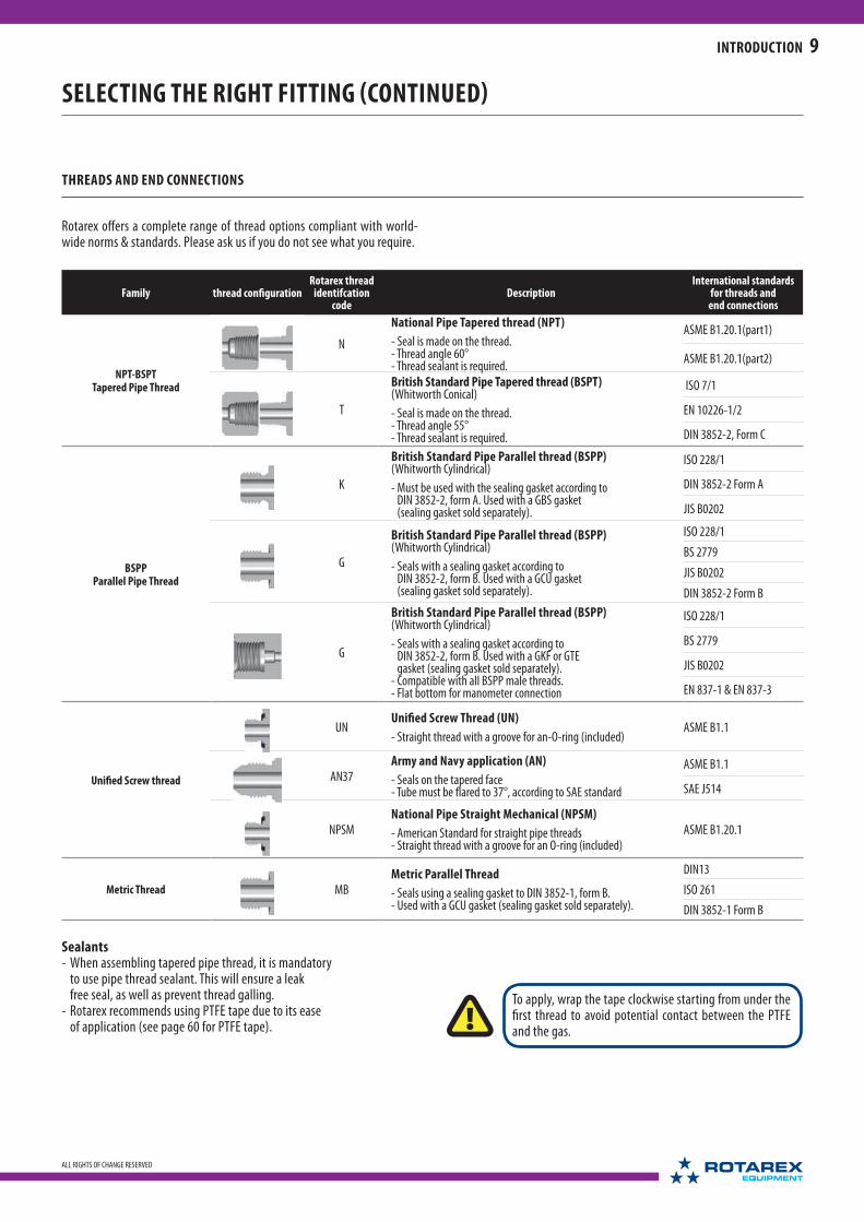
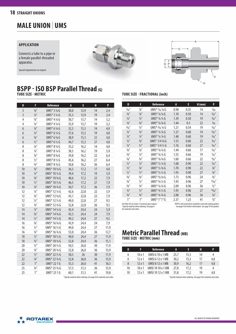
MALE UNION | UMS
APPLICATION
Connects a tube to a pipe or a female taper-threaded apparatus.
Special requirements on request
NPT (N)TUBE SIZE - METRIC (mm)
D F Reference A E H P
3 1⁄16” UMS* 3 1⁄16 N 30,5 12,9 12 2,43 1⁄8” UMS* 3 1⁄8 N 30,5 12,9 12 2,43 ¼” UMS* 3 ¼ N 35,6 12,9 14 2,44 1⁄8” UMS* 4 1⁄8 N 31,2 13,7 12 3,24 ¼” UMS* 4 ¼ N 36,3 13,7 14 3,26 1⁄8” UMS* 6 1⁄8 N 32,8 15,3 14 4,86 ¼” UMS* 6 ¼ N 37,9 15,3 14 4,86 3⁄8” UMS* 6 3⁄8 N 38,4 15,3 19 4,86 ½” UMS* 6 ½ N 44,7 15,3 22 4,88 1⁄8” UMS* 8 1⁄8 N 34,2 16,2 14 4,88 ¼” UMS* 8 ¼ N 38,7 16,2 14 6,48 3⁄8” UMS* 8 3⁄8 N 39.3 16.2 19 6.48 ½” UMS* 8 ½ N 45.6 16.2 22 6.4
10 1⁄8” UMS* 10 1⁄8 N 36,3 17,2 17 4,810 ¼” UMS* 10 ¼ N 40,9 17,2 17 7.910 3⁄8” UMS* 10 3⁄8 N 40,9 17,2 19 7.910 ½” UMS* 10 ½ N 46,5 17,2 22 7.910 ¾” UMS* 10 ¾ N 48,0 17,2 27 7.912 1⁄8” UMS* 12 1⁄8 N 38.8 22.8 22 4.812 ¼” UMS* 12 ¼ N 43,4 22,8 22 7.112 3⁄8” UMS* 12 3⁄8 N 43,4 22,8 22 9,512 ½” UMS* 12 ½ N 49,0 22,8 22 9,512 ¾” UMS* 12 ¾ N 50,5 22,8 27 9,514 ¼” UMS* 14 ¼ N 44,1 24,4 24 7,114 3⁄8” UMS* 14 3⁄8 N 44,1 24,4 24 9.514 ½” UMS* 14 ½ N 44,1 24,4 24 11.114 ¾” UMS* 14 ¾ N 49,0 24,4 27 11,115 3⁄8” UMS* 15 3/8 N 45,6 24,3 24 9,515 ½” UMS* 15 1/2 N 50,5 24,3 24 11,116 3⁄8” UMS* 16 3⁄8 N 44,1 24,4 24 7,116 ½” UMS* 16 ½ N 49,0 24,4 24 11,116 ¾” UMS* 16 ¾ N 50,5 24,4 27 12,718 ½” UMS* 18 ½ N 50,5 24,4 27 11,118 ¾” UMS* 18 ¾ N 50,5 24,4 27 15,918 1” UMS* 18 1’’ N 57,2 24,4 36 15,920 ½” UMS* 20 ½ N 52,3 26,0 30 11,120 ¾” UMS* 20 ¾ N 52,3 26,0 30 15,920 1” UMS* 20 1’’ N 56,4 26,0 36 15,922 ½” UMS* 22 ½ N 52,1 26 30 11,122 ¾” UMS* 22 ¾ N 52,3 26,0 30 15,922 1” UMS* 22 1’’ N 57,1 26,0 36 19,125 ½” UMS* 25 ½ N 56,9 31,3 36 11,125 ¾” UMS* 25 ¾ N 57,5 31,3 36 15,925 1” UMS* 25 1’’ N 62,3 31,3 36 22,2
Hex flats (H) are metric. Fractional upon request*Specify material when ordering. See page 8 for materials and codes.
*Specify material when ordering. See page 8 for materials and codes.

17
ALL RIGHTS OF CHANGE RESERVED
STRAIGHT UNIONS
TUBE SIZE - FRACTIONAL (inch)
D F Reference A E H (mm) P
1⁄16” 1⁄16” UMS* 1⁄16 1⁄16 T 0.94 0.34 8 3⁄16”
1⁄16” 1⁄8” UMS* 1⁄16 1⁄8 T 1.03 0.34 12 3⁄16”
1⁄8” 1⁄8” UMS* 1⁄8 1⁄8 T 1.20 0.50 12 3⁄32”
1⁄8” ¼ ” UMS* 1⁄8 ¼ T 1.40 0.50 14 3⁄32”
1⁄8” 3⁄8” UMS* 1⁄8 3⁄8 T 1.42 0.5 19 3⁄32
3⁄16” ¼ ” UMS* 3⁄16 ¼ T 1.43 0.54 14 1⁄8”
¼ ” 1⁄8” UMS* ¼ 1⁄8 T 1.29 0.60 14 3⁄16”
¼ ” ¼ ” UMS* ¼ ¼ T 1.49 0.60 14 3⁄16”
¼ ” 3⁄8” UMS* ¼ 3⁄8 T 1.51 0.60 19 3⁄16”
¼ ” ½ ” UMS* ¼ ½ T 1.76 0.60 22 3⁄16”
5⁄16” 1⁄8” UMS* 5⁄16 1⁄8 T 1.35 0.64 14 3⁄16”
5⁄16” ¼ ” UMS* 5⁄16 ¼ T 1.52 0.64 14 ¼ ”
3⁄8” 1⁄8” UMS* 3⁄8 1⁄8 T 1.43 0.66 17 3⁄16”
3⁄8” ¼ ” UMS* 3⁄8 ¼ T 1.61 0.66 17 9⁄32”
3⁄8” 3⁄8” UMS* 3⁄8 3⁄8 T 1.61 0.66 19 9⁄32”
3⁄8” ½ ” UMS* 3⁄8 ½ T 1.83 0.66 22 9⁄32”
3⁄8” ¾ ” UMS* 3⁄8 ¾ T 1.89 0.66 27 9⁄32”
½ ” ¼ ” UMS* ½ ¼ T 1.71 0.90 22 9⁄32”
½ ” 3⁄8” UMS* ½ 3⁄8 T 1.71 0.90 22 3⁄8”
½ ” ½ ” UMS* ½ ½ T 1.93 0.90 22 3⁄8”
½ ” ¾ ” UMS* ½ ¾ T 1.99 0.90 27 3⁄8”
5⁄8” 3⁄8” UMS* 5⁄8 3⁄8 T 1.74 0.96 24 3⁄8”
5⁄8” ½ ” UMS* 5⁄8 ½ T 1.93 0.96 24 3⁄8”
¾ ” ¾ ” UMS* ¾ ¾ T 1.99 0.96 27 5⁄8”
¾ ” 1” UMS* ¾ 1’’ T 2.25 0.96 36 5⁄8”
1” ¾ ” UMS* 1’’ ¾ T 2.26 1.23 36 5⁄8”
1” 1” UMS* 1’’ 1’’ T 2.45 1.23 36 7⁄8”
BSPT - ISO BSP Tapered Thread (T)TUBE SIZE - METRIC (mm)
D F Reference A E H P
3 1⁄8” UMS* 3 1⁄8 T 30,5 12,9 12 2,4
3 ¼ ” UMS* 3 ¼ T 35,6 12,9 14 2,4
4 1⁄8” UMS* 4 1⁄8 T 31,2 13,7 12 3,2
4 ¼ ” UMS* 4 ¼ T 36,3 13,7 14 3,2
6 1⁄8” UMS* 6 1⁄8 T 32,8 15,3 14 4,8
6 ¼ ” UMS* 6 ¼ T 37,9 15,3 14 4,8
6 3⁄8” UMS* 6 3⁄8 T 38,4 15,3 19 4,8
6 ½ ” UMS* 6 ½ T 44,7 15,3 22 4,8
8 1⁄8” UMS* 8 1⁄8 T 34,2 16,2 14 4,8
8 ¼ ” UMS* 8 ¼ T 38,7 16,2 14 6,4
8 3⁄8” UMS* 8 3⁄8 T 39.3 16.2 19 6.4
8 ½ ” UMS* 8 ½ T 45.6 16.2 22 6.4
10 1⁄8” UMS* 10 1⁄8 T 36,3 17,2 17 4,8
10 ¼ ” UMS* 10 ¼ T 40,9 17,2 17 7.9
10 3⁄8” UMS* 10 3⁄8 T 40,9 17,2 19 7.9
10 ½ ” UMS* 10 ½ T 46,5 17,2 22 7.9
10 ¾ ” UMS* 10 ¾ T 48,0 17,2 27 7.9
12 ¼ ” UMS* 12 ¼ T 43,4 22,8 22 7.1
12 3⁄8” UMS* 12 3⁄8 T 43,4 22,8 22 9,5
12 ½ ” UMS* 12 ½ T 49,0 22,8 22 9,5
12 ¾ ” UMS* 12 ¾ T 50,5 22,8 27 9,5
14 ¼ ” UMS* 14 ¼ T 44,1 24,4 24 7,1
14 3⁄8” UMS* 14 3⁄8 T 44,1 24,4 24 9.5
14 ½ ” UMS* 14 ½ T 44,1 24,4 24 11.1
14 ¾ ” UMS* 14 ¾ ’’ T 49,0 24,4 27 11,1
15 ½ ” UMS* 15 ½ T 50,5 24,3 24 11,1
16 3⁄8” UMS* 16 3⁄8 T 44,1 24,4 24 7,1
16 ½ ” UMS* 16 ½ T 49,0 24,4 24 11,1
16 ¾ ” UMS* 16 ¾ T 50,5 24,4 27 12,7
18 ½ ” UMS* 18 ½ T 50,5 24,4 27 11,1
18 ¾ ” UMS* 18 ¾ T 50,5 24,4 27 15,9
20 ½ ” UMS* 20 ½ T 52,3 26,0 30 11,1
20 ¾ ” UMS* 20 ¾ T 52,3 26,0 30 15,9
22 ¾ ” UMS* 22 ¾ T 52,3 26,0 30 15,9
22 1” UMS* 22 1’’ T 57,1 26,0 36 19,1
25 ¾ ” UMS* 25 ¾ T 57,5 31,3 36 15,9
25 1” UMS* 25 1’’ T 62,3 31,3 36 22,2
Hex fl ats (H) are metric. Fractional upon request*Specify material when ordering. See page 8 for materials and codes.
APPLICATION
Straight-through bore to join apparatus such as dip tubes and thermocouple sensors.
Special requirements on request
THERMOCOUPLE CONNECTOR | UMTS
For ordering use UMTS instead of UMS
*Specify material when ordering. See page 8 for materials and codes.
Depending on the UMTS reference, the operating pressure might be lower due to the lower wall thickness.
A
D P
H
E
F
18
ALL RIGHTS OF CHANGE RESERVED
STRAIGHT UNIONS
MALE UNION | UMS
APPLICATION
Connects a tube to a pipe or a female parallel-threaded apparatus.
Special requirements on request
BSPP - ISO BSP Parallel Thread (G)TUBE SIZE - METRIC
D F Reference A E H P
3 1⁄8” UMS* 3 1⁄8 G 30,0 12,9 14 2,4
3 ¼” UMS* 3 ¼ G 35,3 12,9 19 2,4
4 1⁄8” UMS* 4 1⁄8 G 30,7 13,7 14 3,2
4 ¼” UMS* 4 ¼ G 35,9 13,7 19 3,2
6 1⁄8” UMS* 6 1⁄8 G 32,3 15,3 14 4,0
6 ¼” UMS* 6 ¼ G 37,6 15,3 19 4,8
6 3⁄8” UMS* 6 3⁄8 G 38,9 15,3 22 4,8
6 ½” UMS* 6 ½ G 44,7 15,3 27 4,8
8 1⁄8” UMS* 8 1⁄8 G 33,2 16,2 14 4,8
8 ¼” UMS* 8 ¼ G 38,5 16,2 19 5,9
8 3⁄8” UMS* 8 3⁄8 G 39,8 16,2 22 6,4
8 ½” UMS* 8 ½ G 45,6 16,2 27 6,4
8 ¾” UMS* 8 ¾ G 50,8 16,2 36 6,4
10 1⁄8” UMS* 10 1⁄8 G 36,5 17,2 17 4,0
10 ¼” UMS* 10 ¼ G 39,4 17,2 19 5,9
10 3⁄8” UMS* 10 3⁄8 G 40,6 17,2 22 7,9
10 ½” UMS* 10 ½ G 46,5 17,2 27 7,9
10 ¾” UMS* 10 ¾ G 50,7 17,2 36 7,9
12 ¼” UMS* 12 ¼ G 42,6 22,8 22 5,9
12 3⁄8” UMS* 12 3⁄8 G 43,1 22,8 22 7,9
12 ½” UMS* 12 ½ G 49,0 22,8 27 9,5
12 ¾” UMS* 12 ¾ G 52,8 22,8 36 9,5
14 ¼” UMS* 14 ¼ G 43,4 24,4 24 5,9
14 3⁄8” UMS* 14 3⁄8 G 43,3 24,4 24 7,9
14 ½” UMS* 14 ½ G 49,2 24,4 27 9,5
16 3⁄8” UMS* 16 3⁄8 G 43,9 24,4 24 7,9
16 ½” UMS* 16 ½ G 49,0 24,4 27 11,9
16 ¾” UMS* 16 ¾ G 53,0 24,4 36 12,7
18 ½” UMS* 18 ½ G 49,0 24,4 27 11,9
18 ¾” UMS* 18 ¾ G 52,8 24,4 36 15,1
20 ½” UMS* 20 ½ G 50,5 26,0 30 11,9
20 ¾” UMS* 20 ¾ G 52,8 26,0 36 15,9
22 ½” UMS* 22 ½ G 50,5 26 30 11,9
22 ¾” UMS* 22 ¾ G 52,8 26,0 36 15,9
22 1” UMS* 22 1 G 55,3 26,0 41 18,3
25 ¾” UMS* 25 ¾ G 57,5 31,3 36 15,9
25 1” UMS* 25 1 G 60,1 31,3 41 19,8
TUBE SIZE - FRACTIONAL (inch)
D F Reference A E H (mm) P
1⁄16” 1⁄8” UMS* 1⁄16 1⁄8 G 0.98 0.35 14 3⁄64
1⁄8” 1⁄8” UMS* 1⁄8 1⁄8 G 1.18 0.50 14 3⁄32”
1⁄8” ¼” UMS* 1⁄8 ¼ G 1.39 0.50 19 3⁄32”
1⁄8” 3⁄8” UMS* 1⁄8 3⁄8 G 1.44 0.5 22 3⁄32
3⁄16” ¼” UMS* 3⁄16 ¼ G 1.21 0.54 19 3⁄32”
¼” 1⁄8” UMS* ¼ 1⁄8 G 1.27 0.60 14 5⁄32”
¼” ¼” UMS* ¼ ¼ G 1.48 0.60 19 3⁄16”
¼” 3⁄8” UMS* 1/4 3⁄8 G 1.53 0.60 22 3⁄16”
¼” ½” UMS* 1/4 ½ G 1.76 0.60 27 3⁄16”
3⁄8” 1⁄8” UMS* 3⁄8 1⁄8 G 1.44 0.66 17 5⁄32”
3⁄8” ¼” UMS* 3⁄8 ¼ G 1.55 0.66 19 7⁄32”
3⁄8” 3⁄8” UMS* 3⁄8 3⁄8 G 1.60 0.66 22 9⁄32”
½” ¼” UMS* ½ ¼ G 1.68 0.90 22 7⁄32”
½” 3⁄8” UMS* ½ 3⁄8 G 1.70 0.90 22 3⁄8”
½” ½” UMS* ½ ½ G 1.93 0.90 27 3⁄8”
5⁄8” 3⁄8” UMS* 5⁄8 3⁄8 G 1.73 0.96 24 3⁄8”
5⁄8” ½” UMS* 5⁄8 ½ G 1.93 0.96 27 15⁄32”
5⁄8” ¾” UMS* 5⁄8 ¾ G 2.09 0.96 36 ½”
¾” ½” UMS* ¾ ½ G 1.93 0.96 27 15⁄32”
¾” ¾” UMS* ¾ ¾ G 2.08 0.96 36 5⁄8”
1” 1” UMS* 1’’ 1’’ G 2.37 1.23 41 7⁄8”BSPP G end connections should be used with sealing gaskets.
See page 9 for further information. See page 59 for gaskets.
Metric Parallel Thread (MB)TUBE SIZE - METRIC (mm)
D F Reference A E H P
6 10 x 1 UMSI 6 10 x 1 MB 25,7 15,3 14 4
6 12 x 1 UMSI 6 12 x 1 MB 30,2 15,3 17 4,8
8 12 x 1 UMSI 8 12 x 1 MB 30,9 16,2 17 4,8
10 10 x 1 UMSI 10 10 x 1 MB 27,8 17,2 19 4
10 12 x 1 UMSI 10 12 x 1 MB 31,8 17,2 19 4,8
Hex flats (H) are metric. Fractional upon request*Specify material when ordering. See page 8 for materials and codes.
*Specify material when ordering. See page 8 for materials and codes. *Specify material when ordering. See page 8 for materials and codes.

A
E
D P
HF
A
D
F
H
19
ALL RIGHTS OF CHANGE RESERVED
STRAIGHT UNIONS
APPLICATION
Straight-through bore to join apparatus such as dip tubes and thermocouple sensors.
Special requirements on request
THERMOCOUPLE CONNECTOR | UMTS
For ordering use UMTS instead of UMS
MALE UNION | UMS
Hex flats (H) are metric. Fractional upon request*Specify material when ordering. See page 8 for materials and codes.
APPLICATION
Connects a tube to a pipe or a female parallel-threaded apparatus.
Special requirements on request
BSPP - ISO BSP Parallel Thread (K)TUBE SIZE - METRIC (mm)
D F Reference A E H P
3 1⁄8” UMS* 3 1⁄8 K 30,0 12,9 14 2,4
3 ¼” UMS* 3 ¼ K 35,3 12,9 19 2,4
4 1⁄8” UMS* 4 1⁄8 K 30,7 13,7 14 3,2
6 1⁄8” UMS* 6 1⁄8 K 32,3 15,3 14 4
6 ¼” UMS* 6 ¼ K 37,6 15,3 19 4,8
6 3⁄8” UMS* 6 3⁄8 K 38,9 15,3 22 4,8
6 ½” UMS* 6 ½ K 44,7 15,3 27 4,8
8 1⁄8” UMS* 8 1⁄8 K 33,2 16,2 14 4,8
8 ¼” UMS* 8 ¼ K 38,5 16,2 19 5,9
8 3⁄8” UMS* 8 3⁄8 K 39,8 16,2 22 6,4
8 ½” UMS* 8 ½ K 45,6 16,2 27 6,4
10 ¼” UMS* 10 ¼ K 39,4 17,2 19 5,9
10 3⁄8” UMS* 10 3⁄8 K 40,6 17,2 22 7,9
10 ½” UMS* 10 ½ K 46,5 17,2 27 7,9
12 ¼” UMS* 12 ¼ K 42,6 22,8 22 5,9
12 3⁄8” UMS* 12 3⁄8 K 43,1 22,8 22 7,9
12 ½” UMS* 12 ½ K 49,0 22,8 27 9,5
12 ¾” UMS* 12 ¾ K 52,8 22,8 36 9,5
14 3⁄8” UMS* 14 3⁄8 K 43,3 24,4 24 7,9
14 ½” UMS* 14 ½ K 49,2 24,4 27 9,5
16 3⁄8” UMS* 16 3⁄8 K 43,9 24,4 24 7,9
16 ½” UMS* 16 ½ K 49,0 24,4 27 11,9
16 ¾” UMS* 16 ¾ K 53,0 24,4 36 12,7
18 ½” UMS* 18 ½ K 49,0 24,4 27 11,9
18 ¾” UMS* 18 ¾ K 52,8 24,4 36 15,1
20 ½” UMS* 20 ½ K 50,5 26,0 30 11,9
20 ¾” UMS* 20 ¾ K 52,8 26,0 36 15,9
22 ¾” UMS* 22 ¾ K 52,8 26,0 36 15,9
22 1” UMS* 22 1 K 55,3 26,0 41 18,3
25 ¾” UMS* 25 ¾ K 57,5 31,3 36 15,9
25 1” UMS* 25 1 K 60,1 31,3 41 19,8
TUBE SIZE - FRACTIONAL (inch)
D F Reference A E H (mm) P
1⁄8” 1⁄8” UMS* 1⁄8 1⁄8 K 1.18 0.50 14 3⁄32”
1⁄8” ¼” UMS* 1⁄8 ¼ K 1.39 0.50 19 3⁄32”
3⁄16” 1⁄8” UMS* 3⁄16 1⁄8 K 1.21 0.54 14 3⁄32”
¼” 1⁄8” UMS* ¼ 1⁄8 K 1.27 0.60 14 5⁄32”
¼” ¼” UMS* ¼ ¼ K 1.48 0.60 19 3⁄16”
¼” 3⁄8” UMS* ¼ 3⁄8 K 1.53 0.60 22 3⁄16”
¼” ½” UMS* ¼ ½ K 1.76 0.60 27 3⁄16”
5⁄16” ¼” UMS* 5⁄16 ¼ K 1.52 0.64 19 7⁄32”
3⁄8” 1⁄8” UMS* 3⁄8 1⁄8 K 1.44 0.66 17 5⁄32”
3⁄8” ¼” UMS* 3⁄8 ¼ K 1.55 0.66 19 7⁄32”
3⁄8” 3⁄8” UMS* 3⁄8 3⁄8 K 1.60 0.66 22 9⁄32”
3⁄8” ½” UMS* 3⁄8 ½ K 1.83 0.66 27 9⁄32”
½” ¼” UMS* ½ ¼ K 1.68 0.90 22 7⁄32”
½” 3⁄8” UMS* ½ 3⁄8 K 1.70 0.90 22 3⁄8”
½” ½” UMS* ½ ½ K 1.93 0.90 27 3⁄8”
½” ¾” UMS* ½ ¾ K 2.08 0.90 36 3⁄8”
¾” ½” UMS* ¾ ½ K 1.93 0.96 27 15⁄32”
¾” ¾” UMS* ¾ ¾ K 2.08 0.96 36 5⁄8”
1” ¾” UMS* 1’’ ¾ K 2.26 1.23 36 5⁄8”
1” 1” UMS* 1’’ 1’’ K 2.37 1.23 41 7⁄8”BSPP K end connections must be used with sealing gaskets. See page 9 for further information. See page 59 for gaskets.
*Specify material when ordering. See page 8 for materials and codes.
Depending on the UMTS reference, the operating pressure might be lower due to the lower wall thickness.

A
E
D P
H
F
20
ALL RIGHTS OF CHANGE RESERVED
STRAIGHT UNIONS
MALE BULKHEAD UNION | UCMS
APPLICATION (NPT)
Connects a tube to a female taper-threaded apparatus or pipe through a wall or panel.
Special requirements on request
For ordering use UCOMSinstead of UCMS
APPLICATION
Connects a tube to a female taper-threaded apparatus or pipe through a wall or panel.
The O-ring ensures a perfect tightness for isolators.
Special requirements on request
MALE BULKHEAD UNION WITH O-RING | UCOMS
*Specify material when ordering. See page 8 for materials and codes.
*Specify material when ordering. See page 8 for materials and codes.
NPT (N)TUBE SIZE - METRIC (mm)
D F Reference A E H P
B’Head
Hole Drill
Size
Max.
B’Head
Thick.
3 1⁄8” UCMS* 3 1⁄8 N 46,5 12,9 12 2,4 8,3 12,7
4 1⁄8” UCMS* 4 1⁄8 N 47,2 13,7 12 3,2 9,8 12,7
6 1⁄8” UCMS* 6 1⁄8 N 49,5 15,3 17 4,8 11,5 10,3
6 ¼ ” UCMS* 6 ¼ N 49,5 15,3 17 4,8 11,5 10,3
6 3⁄8” UCMS* 6 3⁄8 N 53,3 15,3 17 4,8 11,5 10,3
8 1⁄8” UCMS* 8 1⁄8 N 51,9 16,2 17 4,8 13,1 11,1
8 ¼ ” UCMS* 8 ¼ N 56,6 16,2 17 6,4 13,1 11,1
10 ¼ ” UCMS* 10 ¼ N 57,4 17,2 19 7,9 16,3 11,1
12 3⁄8” UCMS* 12 3⁄8 N 63,2 22,8 24 9,5 19,5 12,7
12 ½ ” UCMS* 12 ½ N 68,8 22,8 24 9,5 19,5 12,7
TUBE SIZE - FRACTIONAL (inch)
D F Reference A EH
(mm)P
B’Head Hole Drill
Size
Max. B’Head
Thick.
1⁄8” 1⁄8” UCMS* 1⁄8 1⁄8 N 1.83 0.51 12 3⁄32” 21⁄64” ½ ”
3⁄16” 1⁄8” UCMS* 3⁄16 1⁄8 N 1.86 0.54 12 1⁄8” 25⁄64” ½ ”
¼ ” 1⁄8” UCMS* ¼ 1⁄8 N 1.95 0.60 17 3⁄16” 29⁄64” 17⁄32”
¼ ” ¼ ” UCMS* ¼ ¼ N 2.10 0.60 17 3⁄16” 29⁄64” 17⁄32”
3⁄8” ¼ ” UCMS* 3⁄8 ¼ N 2.26 0.68 19 9⁄32” 37⁄64” 9⁄16”
3⁄8” 3⁄8” UCMS* 3⁄8 3⁄8 N 2.26 0.68 19 9⁄32” 37⁄64” 9⁄16”
3⁄8” ½ ” UCMS* 3⁄8 ½ N 2.51 0.68 22 9⁄32” 37⁄64” 9⁄16”
½ ” 3⁄8” UCMS* ½ 3⁄8 N 2.49 0.90 24 3⁄8” 49⁄64” 19⁄32”
½ ” ½ ” UCMS* ½ ½ N 2.71 0.90 24 3⁄8” 49⁄64” 19⁄32”
¾ ” ¾ ” UCMS* ¾ ¾ N 3 0.96 30 5⁄8” 1 1⁄64” 25⁄32”
1” 1” UCMS* 1” 1” N 3.67 1.23 41 7⁄8” 1 21⁄64” 15⁄16”
Hex fl ats (H) are metric. Fractional upon request*Specify material when ordering. See page 8 for materials and codes.
BSPT - ISO BSP Tapered Thread (T)TUBE SIZE - METRIC (mm)
D F Reference A E H PB’Head
Hole Drill Size
Max.
B’Head
Thick.
3 1⁄8” UCMS* 3 1⁄8 T 46,5 12,9 12 2,4 8,3 12,7
4 1⁄8” UCMS* 4 1⁄8 T 47,2 13,7 12 3,2 9,8 12,7
6 1⁄8” UCMS* 6 1⁄8 T 49,5 15,3 17 4,8 11,5 10,3
6 ¼ ” UCMS* 6 ¼ T 49,5 15,3 17 4,8 11,5 10,3
8 3⁄8” UCMS* 8 3⁄8 T 56,6 16,2 19 6,4 13,1 11,1
TUBE SIZE - FRACTIONAL (inch)
D F Reference A EH
(mm)P
B’Head Hole Drill
Size
Max.
B’Head
Thick.
1⁄8” 1⁄8” UCMS* 1⁄8 1⁄8 T 1.83 0.51 12 3⁄32” 21⁄64” ½ ”
¼ ” ¼ ” UCMS* ¼ ¼ T 2.10 0.60 17 3⁄16” 29⁄64” 17⁄32”
3⁄8” ¼ ” UCMS* 3⁄8 ¼ T 2.26 0.68 19 9⁄32” 37⁄64” 9⁄16”Hex fl ats (H) are metric. Fractional upon request
*Specify material when ordering. See page 8 for materials and codes.

A
E
D P
HF
37°
A
D
E
P
FH
37°
21
ALL RIGHTS OF CHANGE RESERVED
STRAIGHT UNIONS
*Specify material when ordering. See page 8 for materials and codes.
STRAIGHT UNION «AN» | UMS AN
APPLICATION
Connects a tube to a female AN-threaded apparatus.
Special requirements on request
TUBE SIZE - METRIC (mm)
DAN tube
flare sizeReference A E P H F
4 3⁄16" UMS*4 3⁄16 AN 34,1 13,7 3,2 12 3⁄16” - 24
10 ¼" UMS* 10 ¼ AN 40,1 17,2 7,1 17 7⁄16” - 20
10 3⁄8" UMS* 10 3⁄8 AN 40,5 17,2 7,1 17 9⁄16” - 18
12 ½" UMS* 12 ½ AN 46,0 22,8 9,5 22 ¾” - 16
18 ¾" UMS* 18 ¾ AN 54,0 24,4 9,5 27 11⁄16” - 12
TUBE SIZE - FRACTIONAL (inch)
DAN tube
flare sizeReference A E P
H (mm)
F
1⁄8” 1⁄8 UMS* 1⁄8 1⁄8 AN 1.25 0.51 3⁄32 12 5⁄16” - 24
1⁄8” ¼" UMS* 1⁄8 ¼ AN 1.41 0.51 3⁄32 14 7⁄16” - 20
3⁄16” 3⁄16" UMS* 3⁄16 3⁄16 AN 1.34 0.54 1⁄8 12 3⁄16” - 24
¼” ¼" UMS* ¼ ¼ AN 1.50 0.60 3⁄16 14 7⁄16” - 20
5⁄16” 5⁄16" UMS* 5⁄16 5⁄16 AN 1.53 0.64 5⁄32 14 ½” - 20
3⁄8” ¼" UMS* 3⁄8 ¼ AN 1.58 0.68 9⁄32 17 7⁄16” - 20
3⁄8” 3⁄8" UMS* 3⁄8 3⁄8 AN 1.59 0.68 9⁄32 17 9⁄16” - 18
½” ½" UMS* ½ ½ AN 1.81 0.90 3⁄8 22 ¾” - 16
¾” ¾" UMS* ¾ ¾ AN 2.13 0.96 3⁄8 27 11⁄16” - 12
1” 1" UMS* 1” 1” AN 2.43 1.23 7⁄8 36 15⁄16” - 12Hex flats (H) are metric. Fractional upon request
*Specify material when ordering. See page 8 for materials and codes.
BULKHEAD UNION «AN» | UCMS AN
APPLICATION
Connects tubes to a female AN-threaded apparatus through a wall or panel.
Special requirements on request
TUBE SIZE - FRACTIONAL (inch)
DAN tube
flare sizeReference A E H (mm) P
B’Head Hole Drill
Size
Max. B’Head
Thick.F
¼” ¼" UCMS* ¼ ¼ AN 2.14 0.60 17 11⁄64” 29⁄64” 17⁄32” 7⁄16” - 20
3⁄8” 3⁄8" UCMS* 3⁄8 3⁄8 AN 2.28 0.68 19 19⁄64” 37⁄64” 9⁄16” 9⁄16” - 18
½” ½" UCMS* ½ ½ AN 2.59 0.90 24 25⁄64” 49⁄64” 19⁄32” ¾” - 16
¾” ¾" UCMS* ¾ ¾ AN 3.08 0.96 36 39⁄64” 1 1⁄64” 25⁄32” 11⁄16” - 12
1 1" UCMS* 1” 1” AN 3.63 1.23 41 27⁄32” 1 21⁄64” 15⁄16” 15⁄16” - 12Hex flats (H) are metric. Fractional upon request
*Specify material when ordering. See page 8 for materials and codes.

A
D P
E
HF
A
D P
E
HF
22
ALL RIGHTS OF CHANGE RESERVED
STRAIGHT UNIONS
MALE O-RING CONNECTOR (NPSM) | UMOMS
NPSM (NM)TUBE SIZE - METRIC (mm)
D F Reference A E H P
3 1⁄8” UMOMS* 3 1⁄8 32,8 12,9 19 2,46 1⁄8” UMOMS* 6 1⁄8 35,2 15,3 19 4,8
6 3⁄8” UMOMS* 6 3⁄8 39,9 15,3 30 4,8
8 ¼” UMOMS* 8 ¼ 39,3 16,2 24 6,4
10 ¼” UMOMS* 10 ¼ 40,1 17,2 24 7,1
10 ½” UMOMS* 10 ½ 47,3 17,2 36 7,1
12 ½” UMOMS* 12 ½ 49,8 22,8 36 9,5
16 ½” UMOMS* 16 ½ 49,8 24,4 36 13NPSM fittings are supplied with sealing O-rings in Nitrile (NBR). Fluorocarbon (FPM) O-rings are available upon request.
See page 8 for additional information.*Specify material when ordering. See page 8 for materials and codes.
Hex flats (H) are metric. Fractional upon request*Specify material when ordering. See page 8 for materials and codes.
TUBE SIZE - FRACTIONAL (inch)
D F Reference A E H (mm) P
1⁄16” 1⁄8” UMOMS* 1⁄16 1⁄8 1.13 0.34 19 3⁄64”1⁄8” 1⁄8” UMOMS* 1⁄8 1⁄8 1.29 0.5 19 3⁄32”
1⁄8” ¼” UMOMS* 1⁄8 ¼ 1.44 0.5 24 3⁄32”
3⁄16” 1⁄8” UMOMS* 3⁄16 1⁄8 1.34 0.54 19 1⁄8”
¼” 1⁄8” UMOMS* ¼ 1⁄8 1.41 0.60 19 3⁄16”
¼” ¼” UMOMS* ¼ ¼ 1.51 0.60 24 3⁄16”
¼” ½” UMOMS* ¼ ½ 1.81 0.6 36 3⁄16
¼” 3⁄8” UMOMS* ¼ 3⁄8 1.59 0.60 30 3⁄16”
3⁄8” 1⁄8” UMOMS* 3⁄8 1⁄8 1.47 0.68 19 3⁄16”
3⁄8” ¼” UMOMS* 3⁄8 ¼ 1.59 0.68 24 9⁄32”
3⁄8” 3⁄8” UMOMS* 3⁄8 3⁄8 1.66 0.68 30 9⁄32”
3⁄8” ½” UMOMS* 3⁄8 ½ 1.87 0.68 36 9⁄32”
½” ¼” UMOMS* ½ ¼ 1.69 0.90 24 9⁄32”
½” 3⁄8” UMOMS* ½ 3⁄8 1.75 0.90 30 3⁄8”
½” ½” UMOMS* ½ ½ 1.96 0.90 36 3⁄8”
5⁄8” ½” UMOMS* 5⁄8 ½ 1.97 0.96 36 ½”
5⁄8” ¾” UMOMS* 5⁄8 ¾ 2.06 0.96 41 ½”
¾” ½” UMOMS* ¾ ½ 1.97 1.02 36 ½”
¾” ¾” UMOMS* ¾ ¾ 2.06 1.02 41 5⁄8”
1” ¾” UMOMS* 1” ¾ 2.22 1.23 41 5⁄8”
1” 1” UMOMS* 1” 1” 2.37 1.23 46 7⁄8”
MALE O-RING CONNECTOR «UN» | UMOMSS
UN (UN)TUBE SIZE - METRIC (mm)
D F Reference A E H P
3 5⁄16” - 24 UMOMSS* 3 5⁄16 32,8 12,9 14 2,44 3⁄8” - 24 UMOMSS* 4 3⁄8 34,4 13,7 17 3,2
6 7⁄16” - 20 UMOMSS* 6 7⁄16 38,4 15,3 19 4,8
8 ½” - 20 UMOMSS* 8 ½ 40,9 16,2 22 6,4
10 9⁄16” - 18 UMOMSS* 10 9⁄16 42,4 17,2 24 8
12 9⁄16” - 18 UMOMSS* 12 9⁄16 45,7 22,8 24 9,5
12 ¾” - 16 UMOMSS* 12 ¾ 45,8 22,8 30 9,5
18 1 1⁄16”-12 UMOMSS* 18 1”1⁄16 50,6 24,4 38 15
20 1 1⁄16”-12 UMOMSS* 20 1” 1⁄16 52,2 26,0 38 16UN fittings are supplied with sealing O-rings in Nitrile (NBR). Fluorocarbon (FPM) O-rings are available upon request.
See page 8 for additional information.*Specify material when ordering. See page 8 for materials and codes.
TUBE SIZE - FRACTIONAL (inch)
D F Reference A E H (mm) P
1⁄16” 5⁄16” - 24 UMOMSS* 1⁄16 5⁄16 1.29 0.34 14 3⁄64”1⁄8” 5⁄16” - 24 UMOMSS* 1⁄8 5⁄16 1.29 0.51 14 3⁄32”
1⁄8” 9⁄16” - 18 UMOMSS* 1⁄8 9⁄16 1.59 0.51 24 3⁄16
3⁄16” 3⁄8” - 24 UMOMSS* 3⁄16 3⁄8 1.35 0.54 17 1⁄8”
¼” 7⁄16” - 20 UMOMSS* ¼ 7⁄16 1.51 0.60 19 3⁄16”
5⁄16” ½” - 20 UMOMSS* 5⁄16 ½ 1.61 0.64 22 ¼”
3⁄8” 9⁄16” - 18 UMOMSS* 3⁄8 9⁄16 1.67 0.66 24 5⁄8”
½” ¾” - 16 UMOMSS* ½ ¾ 1.80 0.90 30 3⁄8”
¾” 1 1⁄16”-12 UMOMSS* ¾ 1 1⁄16 1.98 0.96 38 19⁄32”Hex flats (H) are metric. Fractional upon request
*Specify material when ordering. See page 8 for materials and codes.
APPLICATION
Connects a tube to a female threaded apparatus with an O-ring face seal connection.
Special requirements on request
APPLICATION
Connects a tube to a female threaded apparatus with an O-ring face seal connection.
Do not mistake NPSM thread with BSPP threads

A
D P
H
F
E
23
ALL RIGHTS OF CHANGE RESERVED
STRAIGHT UNIONS
APPLICATION
Connects a tube to a male NPT-tapered apparatus or pipe.
Special requirements on request
NPT (N)TUBE SIZE - METRIC (mm)
D F Reference A E H P
3 1⁄8” UFS* 3 1⁄8 N 28,7 12,9 14 2,4
3 ¼” UFS* 3 ¼ N 33,5 12,9 19 2,4
4 1⁄8” UFS* 4 1⁄8 N 29,7 13,7 14 2,4
6 1⁄8” UFS* 6 1⁄8 N 31,3 15,3 14 4,8
6 ¼” UFS* 6 ¼ N 35,8 15,3 19 4,8
6 3⁄8” UFS* 6 3⁄8 N 37,6 15,3 22 4,8
6 ½” UFS* 6 ½ N 42,5 15,3 27 4,8
8 1⁄8” UFS* 8 1⁄8 N 32,1 16,2 14 6,4
8 ¼” UFS* 8 ¼ N 37,0 16,2 19 6,4
8 3⁄8” UFS* 8 3⁄8 N 38,5 16,2 22 6,4
8 ½” UFS* 8 ½ N 43,3 16,2 27 6,4
10 1⁄8” UFS* 10 1⁄8 N 33,3 17,2 17 7,9
10 ¼” UFS* 10 ¼ N 37,8 17,2 19 7,9
10 3⁄8” UFS* 10 3⁄8 N 39,4 17,2 22 7,9
10 ½” UFS* 10 ½ N 44,2 17,2 27 7,9
12 ¼” UFS* 12 ¼ N 40,3 22,8 22 9,5
12 3⁄8” UFS* 12 3⁄8 N 41,9 22,8 22 9,5
12 ½” UFS* 12 ½ N 46,7 22,8 27 9,5
12 ¾” UFS* 12 ¾ N 48,9 22,8 32 9,5
14 3⁄8” UFS* 14 3⁄8 N 42,1 24,4 24 11,1
14 ½” UFS* 14 ½ N 46,9 24,4 27 11,1
16 ¼” UFS* 16 ¼ N 41,7 24,4 24 9,5
16 3⁄8” UFS* 16 3⁄8 N 46,9 24,4 24 12,7
16 ½” UFS* 16 ½ N 46,9 24,4 27 12,7
16 ¾” UFS* 16 ¾ N 48,9 24,4 32 12,7
18 ½” UFS* 18 ½ N 46,9 24,4 27 12,7
18 ¾” UFS* 18 ¾ N 48,4 24,4 30 12,7
20 ½” UFS* 20 ½ N 47,9 26,0 30 15,9
20 ¾” UFS* 20 ¾ N 49,7 26,0 36 15,9
22 ¾” UFS* 22 ¾ N 49,7 26,0 36 18,5
22 1” UFS* 22 1” N 57,9 26,0 41 18,5
25 ¾” UFS* 25 ¾ N 53,4 31,3 36 22,2
25 1’’ UFS* 25 1” N 62,3 31,3 41 22,2
TUBE SIZE - FRACTIONAL (inch)
D F Reference A E H (mm) P
1⁄16” 1⁄16” UFS* 1⁄16 1⁄16 N 0.93 0.34 12 3⁄64”
1⁄16” 1⁄8” UFS* 1⁄16 1⁄8 N 0.96 0.34 12 3⁄64”
1⁄16” ¼” UFS* 1⁄16 ¼ N 1.15 0.34 19 3⁄64”
1⁄8” 1⁄8” UFS* 1⁄8 1⁄8 N 1.13 0.51 14 3⁄32”
1⁄8” ¼” UFS* 1⁄8 ¼ N 1.32 0.51 19 3⁄32”
3⁄16” 1⁄8” UFS* 3⁄16 1⁄8 N 1.17 0.54 14 1⁄8”
¼” 1⁄16” UFS* ¼ 1⁄16 N 1.23 0.6 14 3⁄16”
¼” 1⁄8” UFS* ¼ 1⁄8 N 1.23 0.60 14 3⁄16”
¼” ¼” UFS* ¼ ¼ N 1.41 0.60 19 3⁄16”
¼” 3⁄8” UFS* ¼ 3⁄8 N 1.48 0.60 22 3⁄16”
¼” ½” UFS* ¼ ½ N 1.67 0.60 27 3⁄16”
5⁄16” 1⁄8” UFS* 5⁄16 1⁄8 N 1.26 0.64 14 ¼”
5⁄16” ¼” UFS* 5⁄16 ¼ N 1.46 0.64 19 ¼”
3⁄8” 1⁄8” UFS* 3⁄8 1⁄8 N 1.31 0.68 17 9⁄32”
3⁄8” ¼” UFS* 3⁄8 ¼ N 1.49 0.68 19 9⁄32”
3⁄8” 3⁄8” UFS* 3⁄8 3⁄8 N 1.55 0.68 22 9⁄32”
3⁄8” ½” UFS* 3⁄8 ½ N 1.74 0.68 27 9⁄32”
3⁄8” ¾” UFS* 3⁄8 ¾ N 1.88 0.68 30 9⁄32”
½” 1⁄8” UFS* ½ 1⁄8 N 1.4 0.9 22 9⁄32
½” ¼” UFS* ½ ¼ N 1.59 0.90 22 13⁄32”
½” 3⁄8” UFS* ½ 3⁄8 N 1.65 0.90 22 13⁄32”
½” ½” UFS* ½ ½ N 1.84 0.90 27 13⁄32”
½” ¾” UFS* ½ ¾ N 1.9 0.90 30 13⁄32”
5⁄8” 3⁄8” UFS* 5⁄8 3⁄8 N 1.64 0.96 24 ½”
5⁄8” ½” UFS* 5⁄8 ½ N 1.85 0.96 27 ½”
5⁄8” ¾” UFS* 5⁄8 ¾ N 1.9 0.96 30 ½”
¾” ½” UFS* ¾ ½ N 1.85 0.96 27 5⁄8”
¾” ¾” UFS* ¾ ¾ N 1.91 0.96 30 5⁄8”
7⁄8” ¾” UFS* 7⁄8 ¾ N 1.96 1.02 30 ¾”
1” ¾” UFS* 1” ¾ N 2.10 1.23 36 7⁄8”
1” 1” UFS* 1” 1” N 2.45 1.23 41 7⁄8”Hex flats (H) are metric. Fractional upon request
*Specify material when ordering. See page 8 for materials and codes.
*Specify material when ordering. See page 8 for materials and codes.
FEMALE UNION | UFS

A
D P
H
F
E
24
ALL RIGHTS OF CHANGE RESERVED
STRAIGHT UNIONS
TUBE SIZE - FRACTIONAL (inch)
D F Reference A E H (mm) P
1⁄16” 1⁄8” UFS* 1⁄16 1⁄8 T 0.96 0.34 12 3⁄64”
1⁄8” 1⁄8” UFS* 1⁄8 1⁄8 T 1.13 0.51 14 3⁄32”
1⁄8” ¼” UFS* 1⁄8 ¼ T 1.32 0.51 19 3⁄32”
¼” 1⁄8” UFS* ¼ 1⁄8 T 1.23 0.60 14 3⁄16”
¼” ¼” UFS* ¼ ¼ T 1.41 0.60 19 3⁄16”
¼” 3⁄8” UFS* ¼ 3⁄8 T 1.48 0.60 22 3⁄16”
¼” ½” UFS* ¼ ½ T 1.67 0.60 27 3⁄16”
3⁄8” 1⁄8” UFS* 3⁄8 1⁄8 T 1.31 0.68 17 9⁄32”
3⁄8” ¼” UFS* 3⁄8 ¼ T 1.49 0.68 19 9⁄32”
3⁄8” 3⁄8” UFS* 3⁄8 3⁄8 T 1.55 0.68 22 9⁄32”
3⁄8” ½” UFS* 3⁄8 ½ T 1.74 0.68 27 9⁄32”
½” ¼” UFS* ½ ¼ T 1.59 0.90 22 13⁄32”
½” 3⁄8” UFS* ½ 3⁄8 T 1.65 0.90 22 13⁄32”
½” ½” UFS* ½ ½ T 1.84 0.90 27 13⁄32”
½” ¾” UFS* ½ ¾ T 1.9 0.90 30 13⁄32”
¾” ¾” UFS* ¾ ¾ T 1.91 0.96 30 5⁄8”
APPLICATION
Connects a tube to a male BSPT-tapered apparatus or pipe.
Special requirements on request
Hex flats (H) are metric. Fractional upon request*Specify material when ordering. See page 8 for materials and codes.
*Specify material when ordering. See page 8 for materials and codes.
FEMALE UNION |
BSPT - ISO BSP Tapered Thread (T)TUBE SIZE - METRIC (mm)
D F Reference A E H P
3 1⁄8” UFS* 3 1⁄8 T 28,7 12,9 14 2,4
4 1⁄8” UFS* 4 1⁄8 T 29,7 13,7 14 2,4
6 1⁄8” UFS* 6 1⁄8 T 31,3 15,3 14 4,8
6 ¼” UFS* 6 ¼ T 35,8 15,3 19 4,8
6 3⁄8” UFS* 6 3⁄8 T 37,6 15,3 22 4,8
6 ½” UFS* 6 ½ T 42,5 15,3 27 4,8
8 1⁄8” UFS* 8 1⁄8 T 32,1 16,2 14 6,4
8 ¼” UFS* 8 ¼ T 37,0 16,2 19 6,4
8 3⁄8” UFS* 8 3⁄8 T 38,5 16,2 22 6,4
8 ½” UFS* 8 ½ T 43,3 16,2 27 6,4
10 1⁄8” UFS* 10 1⁄8 T 33,3 17,2 17 7,9
10 ¼” UFS* 10 ¼ T 37,8 17,2 19 7,9
10 3⁄8” UFS* 10 3⁄8 T 39,4 17,2 22 7,9
10 ½” UFS* 10 ½ T 44,2 17,2 27 7,9
12 ¼” UFS* 12 ¼ T 40,3 22,8 22 9,5
12 3⁄8” UFS* 12 3⁄8 T 41,9 22,8 22 9,5
12 ½” UFS* 12 ½ T 46,7 22,8 27 9,5
14 3⁄8” UFS* 14 3⁄8 T 42,1 24,4 24 11,1
14 ½” UFS* 14 ½ T 46,9 24,4 27 11,1
16 3⁄8” UFS* 16 3⁄8 T 46,9 24,4 24 12,7
16 ½” UFS* 16 ½ T 46,9 24,4 27 12,7
16 ¾” UFS* 16 ¾ T 48,9 24,4 32 12,7
18 ½” UFS* 18 ½ T 46,9 24,4 27 12,7
20 ½” UFS* 20 ½ T 47,9 26,0 30 15,9
20 ¾” UFS* 20 ¾ T 49,7 26,0 36 15,9
22 ¾” UFS* 22 ¾ T 49,7 26,0 36 18,5
22 1” UFS* 22 1” T 57,9 26,0 41 18,5
25 ¾” UFS* 25 ¾ T 53,4 31,3 36 22,2
25 1’’ UFS* 25 1” T 62,3 31,3 41 22,2

25
ALL RIGHTS OF CHANGE RESERVED
STRAIGHT UNIONS
BSPP - ISO BSPP Parallel Thread (G)TUBE SIZE - METRIC (mm)
D F Reference A E H (mm) P
3 ¼” UFS* 3 ¼ G 35,3 12,9 19 2,4
4 1⁄8” UFS* 4 1⁄8 G 29,6 13,7 14 2,4
4 ¼” UFS* 4 ¼ G 35,9 13,7 19 2,4
4 3⁄8” UFS* 4 3⁄8 G 39,2 13,7 22 2,4
4 ½” UFS* 4 ½ G 40,6 13,7 27 2,4
6 1⁄8” UFS* 6 1⁄8 G 31,3 15,3 14 4,8
6 ¼” UFS* 6 ¼ G 37,6 15,3 19 4,8
6 3⁄8” UFS* 6 3⁄8 G 37,6 15,3 22 4,8
6 ½” UFS* 6 ½ G 43,5 15,3 27 4,8
8 1⁄8” UFS* 8 1⁄8 G 32,0 16,2 14 4,5
8 ¼” UFS* 8 ¼ G 38,5 16,2 19 5,5
8 3⁄8” UFS* 8 3⁄8 G 36,2 16,2 22 6,4
8 ½” UFS* 8 ½ G 41,0 16,2 27 6,4
10 1⁄8” UFS* 10 1⁄8 G 33,1 17,2 17 4,5
10 ¼” UFS* 10 ¼ G 39,4 17,2 19 5,5
10 3⁄8” UFS* 10 3⁄8 G 38,8 17,2 22 6,4
10 ½” UFS* 10 ½ G 42,1 17,2 27 7,0
12 ¼” UFS* 12 ¼ G 41,9 22,8 22 5,5
12 3⁄8” UFS* 12 3⁄8 G 44,4 22,8 22 6,4
12 ½” UFS* 12 ½ G 48,2 22,8 27 7,0
12 ¾” UFS* 12 ¾ G 48,9 22,8 32 9,5
14 3⁄8” UFS* 14 3⁄8 G 41,7 24,4 24 6,5
14 ½” UFS* 14 ½ G 46,5 24,4 27 7,1
16 ½” UFS* 16 ½ G 46,5 24,4 27 7,1
18 ½” UFS* 18 ½ G 46,5 24,4 27 7,1
18 ¾” UFS* 18 ¾ G 48,9 24,4 32 15
20 ½” UFS* 20 ½ G 54,3 26,0 30 7,0
22 ½” UFS* 22 ½ G 54,3 26,0 30 7,0
TUBE SIZE - FRACTIONAL (inch)
D F Reference A E H (mm) P
1⁄8” ¼” UFS* 1⁄8 ¼ G 1.39 0.51 19 3⁄32”
¼” 1⁄8” UFS* ¼ 1⁄8 G 1.25 0.6 14 3⁄16”
¼” ¼” UFS* ¼ ¼ G 1.48 0.60 19 3⁄16”
¼” 3⁄8” UFS* ¼ 3⁄8 G 1.48 0.60 22 3⁄16”
¼” ½” UFS* ¼ ½ G 1.61 0.60 27 3⁄16”
5⁄16” ¼” UFS* 5⁄16 ¼ G 1.52 0.64 19 7⁄32”
5⁄16” ½” UFS* 5⁄16 ½ G 1.61 0.64 27 9⁄32”
3⁄8” ¼” UFS* 3⁄8 ¼ G 1.55 0.66 19 7⁄32”
3⁄8” 3⁄8” UFS* 3⁄8 3⁄8 G 1.53 0.66 22 17⁄64”
3⁄8” ½” UFS* 3⁄8 ½ G 1.66 0.66 27 9⁄32”
½” 3⁄8” UFS* ½ 3⁄8 G 1.75 0.9 22 17⁄64”
½” ½” UFS* ½ ½ G 1.90 0.9 27 9⁄32”
½” ¾” UFS* ½ ¾ G 1.94 0.9 32 3⁄8”BSPP G end connections should be used with sealing gaskets.
See page 9 for further information. See page 59 for gaskets.
FEMALE UNION | UFS
APPLICATION
Connects a tube to a male BSPP parallel-threaded apparatus or pipe.
Special requirements on request
Hex flats (H) are metric. Fractional upon request*Specify material when ordering. See page 8 for materials and codes.
*Specify material when ordering. See page 8 for materials and codes.

A
D P F
H
E
A
D P F
H
E
26
ALL RIGHTS OF CHANGE RESERVED
STRAIGHT UNIONS
NPT (N)TUBE SIZE - METRIC (mm)
D F Reference A E H PB'head
Hole drill sizeMax. B'head
Thickness
4 ¼” UCFS* 4 ¼ N 50,3 13,7 19 2,4 9,8 12,7
6 1⁄8” UCFS* 6 1⁄8 N 47,1 15,3 17 4,8 11,5 10,3
6 ¼” UCFS* 6 ¼ N 51,9 15,3 19 4,8 11,5 10,3
10 ¼” UCFS* 10 ¼ N 54,3 17,2 19 7,9 16,3 11,1
12 ¼” UCFS* 12 ¼ N 60,0 22,8 22 9,5 19,5 12,7
12 3⁄8” UCFS* 12 3⁄8 N 61,7 22,8 22 9,5 19,5 12,7
12 ½” UCFS* 12 ½ N 66,5 22,8 27 9,5 19,5 12,7
16 ½” UCFS* 16 ½ N 67,1 24,4 27 12,7 22,5 12,7
TUBE SIZE - FRACTIONAL (inch)
D F Reference A E H (mm) PB'head
Hole drill sizeMax. B'head
Thickness
1⁄8” 1⁄8” UCFS* 1⁄8 1⁄8 N 1.76 0.51 14 3⁄32” 21⁄64” ½”
¼” 1⁄8” UCFS* ¼ 1⁄8 N 1.85 0.60 17 3⁄16” 29⁄64” 17⁄32”
¼” ¼” UCFS* ¼ ¼ N 2.04 0.60 19 3⁄16” 29⁄64” 17⁄32”
3⁄8” ¼” UCFS* 3⁄8 ¼ N 2.14 0.68 19 9⁄32” 37⁄64” 9⁄16”
3⁄8” ½” UCFS* 3⁄8 ½ N 2,43 0,68 27 9⁄32 37⁄64” 9⁄16”
½” 3⁄8” UCFS* ½ 3⁄8 N 2.43 0.90 24 3⁄8” 49⁄64” 19⁄32”
½” ½” UCFS* ½ ½ N 2.62 0.90 27 3⁄8” 49⁄64” 19⁄32”
BSPT - ISO BSP Tapered Thread (T)TUBE SIZE - METRIC (mm)
D F Reference A E H PB'head
Hole drill sizeMax. B'head
Thickness
3 1⁄8” UCFS* 3 1⁄8 T 44,6 12,9 14 2,4 8,3 12,7
6 ¼” UCFS* 6 ¼ T 51,9 15,3 19 4,8 11,5 10,3
10 ¼” UCFS* 10 ¼ T 54,3 17,2 19 7,9 16,3 11,1
12 ½” UCFS* 12 ½ T 66,5 22,8 27 9,5 19,5 12,7
TUBE SIZE - FRACTIONAL (inch)
D F Reference A E H (mm) PB'head
Hole drill sizeMax. B'head
Thickness
¼” ¼” UCFS* ¼ ¼ T 2.04 0.60 19 3⁄16” 29⁄64” 17⁄32”
3⁄8” ¼” UCFS* 3⁄8 ¼ T 2.14 0.68 19 9⁄32” 37⁄64” 9⁄16”
BSPP - ISO BSP Parallel Thread (G)TUBE SIZE - METRIC (mm)
D F Reference A E H PB'head
Hole drill sizeMax. B'head
Thickness
6 1⁄8” UCFS* 6 1⁄8 G 47,1 15,3 17 4,8 11,5 10,3
8 ¼” UCFS* 8 ¼ G 54,2 16,2 19 5,5 13,1 11,1
10 3⁄8” UCFS* 10 3⁄8 G 56,6 17,2 22 6,4 16,3 11,1
12 3⁄8” UCFS* 12 3⁄8 G 61,7 22,8 22 9,5 19,5 12,7
12 ½” UCFS* 12 ½ G 66,5 22,8 27 9,5 19,5 12,7BSPP G end connections should be used with sealing gaskets.
See page 9 for further information. See page 59 for gaskets.*Specify material when ordering. See page 8 for materials and codes.
Hex flats (H) are metric. Fractional upon request*Specify material when ordering. See page 8 for materials and codes.
Hex flats (H) are metric. Fractional upon request*Specify material when ordering. See page 8 for materials and codes.
*Specify material when ordering. See page 8 for materials and codes.
*Specify material when ordering. See page 8 for materials and codes.
FEMALE BULKHEAD UNION | UCFS
APPLICATION
Connects a tube to a male threaded apparatus or pipe through a wall or panel.
Special requirements on request

A
E
D P
H
SWD
J
A
E
D P
H
BW
37°
A
E
D P
H
SWD
J
A
E
D P
H
BW
37°
27
ALL RIGHTS OF CHANGE RESERVED
STRAIGHT UNIONS
TUBE SOCKET WELD UNION | UMSWS
APPLICATION
Connects a tube to another tube via a socket weld.
Special requirements on request
MALE PIPE WELD CONNECTOR | UMBWS
TUBE SIZE - METRIC (mm)
DNominal Pipe size
Reference A E H BW
3 1⁄8” UMBWS* 3 1⁄8 30,5 12,9 12 10,28
4 1⁄8” UMBWS* 4 1⁄8 31,2 13,7 12 10,28
6 1⁄8” UMBWS* 6 1⁄8 32,8 15,3 14 10,28
6 ¼” UMBWS* 6 ¼ 37,9 15,3 14 13,72
6 ½” UMBWS* 6 ½ 44,8 15,3 22 21,34
8 1⁄8” UMBWS* 8 1⁄8 34,2 16,2 14 10,28
8 ¼” UMBWS* 8 ¼ 38,7 16,2 14 13,72
8 3⁄8” UMBWS* 8 3⁄8 39,1 16,2 19 17,15
8 ½” UMBWS* 8 ½ 45,6 16,2 22 21,34
10 ¼” UMBWS* 10 ¼ 40,9 17,2 17 13,72
10 3⁄8” UMBWS* 10 3⁄8 40,9 17,2 19 17,15
10 ½” UMBWS* 10 ½ 46,5 17,2 22 21,34
12 3⁄8” UMBWS* 12 3⁄8 43,4 22,8 22 17,15
12 ½” UMBWS* 12 ½ 49,0 22,8 22 21,34
12 ¾” UMBWS* 12 ¾ 50,5 22,8 27 26,67
14 ¼” UMBWS* 14 ¼ 44,1 24,4 24 13,72
14 ½” UMBWS* 14 ½ 44,1 24,4 24 21,34
14 3⁄8” UMBWS* 14 3⁄8 44,1 24,4 24 17,15
16 ½” UMBWS* 16 ½ 49,0 24,4 24 21,34
TUBE SIZE - FRACTIONAL (inch)
DNominal Pipe size
Reference A E H (mm) BW
1⁄8” 1⁄8” UMBWS* 1⁄8 1⁄8 1.20 0.50 12 0.405
3⁄16” 1⁄8” UMBWS* 3⁄16 1⁄8 1.23 0.54 12 0.405
¼” 1⁄8” UMBWS* ¼ 1⁄8 1.29 0.60 14 0.405
¼” ¼” UMBWS* ¼ ¼ 1.49 0.60 14 0.540
5⁄16” 1⁄8” UMBWS* 5⁄16 1⁄8 1.35 0.64 14 0.405
5⁄16” ¼” UMBWS* 5⁄16 ¼ 1.56 0.64 14 0.540
3⁄8” ¼” UMBWS* 3⁄8 ¼ 1.61 0.66 17 0.540
3⁄8” 3⁄8” UMBWS* 3⁄8 3⁄8 1.61 0.66 19 0.675
3⁄8” ½” UMBWS* 3⁄8 ½ 1.83 0.66 22 0.840
½” 3⁄8” UMBWS* ½ 3⁄8 1.71 0.90 22 0.675
½” ½” UMBWS* ½ ½ 1.93 0.90 22 0.840
½” ¾” UMBWS* ½ ¾ 1.99 0.90 27 1.050
5⁄8” ½” UMBWS* 5⁄8 ½ 1.93 0.96 24 0.840
¾” ½” UMBWS* ¾ ½ 1.99 0.96 27 0.840
¾” ¾” UMBWS* ¾ ¾ 1.99 0.96 27 1.050
1” 1” UMBWS* 1’’ 1’’ 2.45 1.23 36 1.315
Hex flats (H) are metric. Fractional upon request*Specify material when ordering. See page 8 for materials and codes.
Hex flats (H) are metric. Fractional upon request*Specify material when ordering. See page 8 for materials and codes.
*Specify material when ordering. See page 8 for materials and codes.
TUBE SIZE - METRIC (mm)
D Reference A E H J P SW
3 UMSWS* 3 29,0 12,9 12 6,4 2,4 7,9
4 UMSWS* 4 31,4 13,7 12 7,1 3,2 9,5
6 UMSWS* 6 33,5 15,3 14 7,9 4,8 11,1
8 UMSWS* 8 35,5 16,2 14 8,7 6,4 12,7
10 UMSWS* 10 37,6 17,2 17 9,5 7,9 15,9
12 UMSWS* 12 41,1 22,8 22 12,7 9,5 19,1
14 UMSWS* 14 42,1 24,4 24 14,3 11 22,2
16 UMSWS* 16 42,1 24,4 24 14,3 13 22,2
20 UMSWS* 20 45,2 26,0 30 15,9 16 27,0
TUBE SIZE - FRACTIONAL (inch)
D Reference A E H (mm) J P SW
1⁄8” UMSWS* 1⁄8 1.14 0.5 12 0.25 3⁄32” 0.31
¼” UMSWS* ¼ 1.32 0.60 14 0.31 3⁄16” 0.44
3⁄8” UMSWS* 3⁄8 1.48 0.66 17 0.38 9⁄32” 0.63
½” UMSWS* ½ 1.62 0.90 22 0.50 13⁄32” 0.75
5⁄8” UMSWS* 5⁄8 1.66 0.96 24 0.56 ½” 0.88
¾” UMSWS* ¾ 1.71 0.96 27 0.56 5⁄8” 1.06
1” UMSWS* 1” 2.07 1.23 36 0.75 7⁄8” 1.31
APPLICATION
Connects a tube to a pipe via a butt weld.
Special requirements on request
*Specify material when ordering. See page 8 for materials and codes.

A
P
D
F
H
L
E
45°
A
D E
H
P
A
D
28
ALL RIGHTS OF CHANGE RESERVED
ELBOW UNIONS
ELBOW | EQS
APPLICATION
Connects two tubes of the same dimension at a 90º angle.
Special requirements on request
TUBE SIZE - METRIC (mm)
D Reference A E H P
3 EQS* 3 23,25 12,9 12 2,4
4 EQS* 4 24,05 13,7 12 3,2
6 EQS* 6 27,2 15,3 14 4,8
8 EQS* 8 28,1 16,2 14 6,4
10 EQS* 10 32,6 17,2 19 7,1
12 EQS* 12 36,3 22,8 22 9,5
14 EQS* 14 37,1 24,4 24 11,1
16 EQS* 16 37,1 24,4 24 12,7
18 EQS* 18 39,5 24,4 27 15,1
20 EQS* 20 41,9 26,0 30 15,9
22 EQS* 22 41,9 26,0 30 19,1
25 EQS* 25 45,6 31,3 36 22,2
TUBE SIZE - FRACTIONAL (inch)
D Reference A E H (mm) P
1⁄16” EQS* 1⁄16 0.70 0.34 12 3⁄64”
1⁄8” EQS* 1⁄8 0.91 0.51 12 3⁄32”
3⁄16” EQS* 3⁄16 0.94 0.54 12 1⁄8”
¼” EQS* ¼ 1.07 0.60 14 3⁄16”
5⁄16” EQS* 5⁄16 1.11 0.64 14 ¼”
3⁄8” EQS* 3⁄8 1.27 0.68 19 9⁄32”
½” EQS* ½ 1.43 0.90 22 13⁄32”
5⁄8” EQS* 5⁄8 1.46 0.96 24 ½”
¾” EQS* ¾ 1.56 0.96 27 5⁄8”
7⁄8” EQS* 7⁄8 1.62 1.02 30 ¾”
1” EQS* 1’’ 1.80 1.23 36 7⁄8”Hex flats (H) are metric. Fractional upon request
*Specify material when ordering. See page 8 for materials and codes.
Hex flats (H) are metric. Fractional upon request*Specify material when ordering. See page 8 for materials and codes.
*Specify material when ordering. See page 8 for materials and codes.
*Specify material when ordering. See page 8 for materials and codes.
45° MALE ELBOW | EQM45S
APPLICATION
Connects a tube with a female taper-threaded apparatus or pipe at a 45º angle.
Special requirements on request
NPT (N)TUBE SIZE - METRIC (mm)
D F Reference A E H L P
6 1⁄8” EQM45S* 6 1⁄8 N 27,2 15,3 14 19,1 4,8
6 ¼” EQM45S* 6 ¼ N 27,2 15,3 14 23,8 4,8
TUBE SIZE - FRACTIONAL (inch)
D F Reference A E H (mm) L P
¼” 1⁄8” EQM45S* ¼ 1⁄8 N 1.07 0.60 14 ¾” 3⁄16”
¼” ¼” EQM45S* ¼ ¼ N 1.07 0.60 14 15⁄16” 3⁄16”
3⁄8” 1⁄8” EQM45S* 3⁄8 1⁄8 N 1.27 0.68 19 7⁄8” 3⁄16”
3⁄8” ¼” EQM45S* 3⁄8 ¼ N 1.27 0.68 19 1 1⁄16” 9⁄32”
½” ¼” EQM45S* ½ ¼ N 1.43 0.90 22 1 1⁄8” 9⁄32”
½” 3⁄8” EQM45S* ½ 3⁄8 N 1.43 0.90 22 1 1⁄8” 3⁄8”

A
E
D
P
H
F
29
ALL RIGHTS OF CHANGE RESERVED
ELBOW UNIONS
*Specify material when ordering. See page 8 for materials and codes.
NPT (N)TUBE SIZE - METRIC (mm)
D F Reference A E H (mm) P
3 1⁄8” EQMS* 3 1⁄8 N 23,3 12,9 12 2,4
3 ¼” EQMS* 3 ¼ N 24,9 12,9 14 2,4
4 1⁄8” EQMS* 4 1⁄8 N 24,1 13,7 12 3,2
6 1⁄8” EQMS* 6 1⁄8 N 27,2 15,3 14 4,8
6 ¼” EQMS* 6 ¼ N 27,2 15,3 14 4,8
6 3⁄8” EQMS* 6 3⁄8 N 29,7 15,3 19 4,8
6 ½” EQMS* 6 ½ N 31.9 15,3 22 4,8
8 1⁄8” EQMS* 8 1⁄8 N 28,1 16,2 14 4,8
8 ¼” EQMS* 8 ¼ N 28,1 16,2 14 6,4
8 3⁄8” EQMS* 8 3⁄8 N 28.1 16.2 19 6.4
8 ½” EQMS* 8 ½ N 28.1 16.2 22 6.4
10 1⁄8” EQMS* 10 1⁄8 N 32,2 17,2 19 7,1
10 ¼” EQMS* 10 ¼ N 32,2 17,2 19 7.1
10 3⁄8” EQMS* 10 3⁄8 N 31,0 17,2 19 7,1
10 ½” EQMS* 10 ½ N 31,8 17,2 22 7,1
12 ¼” EQMS* 12 ¼ N 36,3 22,8 22 7,1
12 3⁄8” EQMS* 12 3⁄8 N 36,3 22,8 22 9,5
12 ½” EQMS* 12 ½ N 36,3 22,8 22 9,5
12 ¾” EQMS* 12 ¾ N 36.3 22.8 27 9.5
14 3⁄8” EQMS* 14 3⁄8 N 36,6 24,4 24 7,1
14 ½” EQMS* 14 ½ N 36,6 24,4 24 9,5
16 3⁄8” EQMS* 16 3⁄8 N 37,1 24,4 24 9,5
16 ½” EQMS* 16 ½ N 37,1 24,4 24 11,9
16 ¾” EQMS* 16 ¾ N 37.1 24.4 27 13
18 ½” EQMS* 18 ½ N 39,5 26,0 27 11,9
18 ¾” EQMS* 18 ¾ N 39,5 26,0 27 15,1
20 ½” EQMS* 20 ½ N 41,1 26,0 30 11,9
20 ¾” EQMS* 20 ¾ N 41,1 26,0 30 15,9
22 ¾” EQMS* 22 ¾ N 41,1 26,0 30 15,9
22 1” EQMS* 22 1’’ N 41.1 26.0 36 18.5
25 ¾” EQMS* 25 ¾ N 45,6 31,3 36 15,9
25 1” EQMS* 25 1’’ N 45,6 31,3 36 22,2
Hex flats (H) are metric. Fractional upon request*Specify material when ordering. See page 8 for materials and codes.
MALE ELBOW | EQMS
APPLICATION
Connects a tube to a female threaded apparatus or pipe on a 90º angle.
Special requirements on request
TUBE SIZE - FRACTIONAL (inch)
D F Reference A E H (mm) P
1⁄16” 1⁄16” EQMS* 1⁄16 1⁄16 N 0.70 0.34 8 3⁄16”
1⁄16” 1⁄8” EQMS* 1⁄16 1⁄8 N 0.92 0.34 12 3⁄16”
1⁄8” 1⁄8” EQMS* 1⁄8 1⁄8 N 0.92 0.51 12 3⁄32”
1⁄8” ¼” EQMS* 1⁄8 ¼ N 0.98 0.51 14 3⁄32”
3⁄16” 1⁄8” EQMS* 3⁄16 1⁄8 N 0.95 0.54 12 3⁄32”
¼” 1⁄8” EQMS* ¼ 1⁄8 N 1.46 0.96 14 3⁄16”
¼” ¼” EQMS* ¼ ¼ N 1.56 1.02 14 3⁄16”
¼” 3⁄8” EQMS* ¼ 3⁄8 N 1.17 0.60 19 3⁄16”
¼” ½” EQMS* ¼ ½ N 1.20 0.60 22 3⁄16”
5⁄16” 1⁄8” EQMS* 5⁄16 1⁄8 N 1.11 0.64 14 3⁄16”
5⁄16” ¼” EQMS* 5⁄16 ¼ N 1.11 0.64 14 ¼”
3⁄8” 1⁄8” EQMS* 3⁄8 1⁄8 N 1.80 1.23 19 3⁄16”
3⁄8” ¼” EQMS* 3⁄8 ¼ N 1.80 1.23 19 9⁄32”
3⁄8” 3⁄8” EQMS* 3⁄8 3⁄8 N 1.22 0.68 19 9⁄32”
3⁄8” ½” EQMS* 3⁄8 ½ N 1.25 0.68 22 9⁄32”
½” ¼” EQMS* ½ ¼ N 1.43 0.90 22 9⁄32”
½” 3⁄8” EQMS* ½ 3⁄8 N 1.43 0.90 22 3⁄8”
½” ½” EQMS* ½ ½ N 1.43 0.90 22 3⁄8”
½” ¾” EQMS* ½ ¾ N 1.56 0.90 22 3⁄8"
5⁄8” 3⁄8” EQMS* 5⁄8 3⁄8 N 1.46 0.96 24 3⁄8”
5⁄8” ½” EQMS* 5⁄8 ½ N 1.46 0.96 24 ½”
¾” ½” EQMS* ¾ ½ N 1.56 1.02 27 5⁄8”
¾” ¾” EQMS* ¾ ¾ N 1.56 1.02 27 5⁄8”
7⁄8” ¾” EQMS* 7⁄8 ¾ N 1.62 1.02 30 ¾”
1” ¾” EQMS* 1” ¾ N 1.80 1.23 36 5⁄8”
1” 1” EQMS* 1” 1’’ N 1.80 1.23 36 7⁄8”

30
ALL RIGHTS OF CHANGE RESERVED
ELBOW UNIONS
BSPT - ISO BSP Tapered Thread (T)TUBE SIZE - METRIC (mm)
D F Reference A E H (mm) P
3 1⁄8” EQMS* 3 1⁄8 T 23,3 12,9 12 2,4
3 ¼” EQMS* 3 ¼ T 24,9 12,9 14 2,4
4 1⁄8” EQMS* 4 1⁄8 T 24,1 13,7 12 3,2
6 1⁄8” EQMS* 6 1⁄8 T 27,2 15,3 14 4,8
6 ¼” EQMS* 6 ¼ T 27,2 15,3 14 4,8
6 3⁄8” EQMS* 6 3⁄8 T 29,7 15,3 19 4,8
6 ½” EQMS* 6 ½ T 31.9 15,3 22 4,8
8 1⁄8” EQMS* 8 1⁄8 T 28,1 16,2 14 4,8
8 ¼” EQMS* 8 ¼ T 28,1 16,2 14 6,4
8 3⁄8” EQMS* 8 3⁄8 T 28.1 16.2 19 6.4
8 ½” EQMS* 8 ½ T 28.1 16.2 22 6.4
10 1⁄8” EQMS* 10 1⁄8 T 32,2 17,2 19 7,1
10 ¼” EQMS* 10 ¼ T 32,2 17,2 19 7.1
10 3⁄8” EQMS* 10 3⁄8 T 31,0 17,2 19 7,1
10 ½” EQMS* 10 ½ T 31,8 17,2 22 7,1
12 ¼” EQMS* 12 ¼ T 36,3 22,8 22 7,1
12 3⁄8” EQMS* 12 3⁄8 T 36,3 22,8 22 9,5
12 ½” EQMS* 12 ½ T 36,3 22,8 22 9,5
12 ¾” EQMS* 12 ¾ T 36.3 22.8 27 9.5
14 3⁄8” EQMS* 14 3⁄8 T 36,6 24,4 24 7,1
14 ½” EQMS* 14 ½ T 36,6 24,4 24 9,5
16 3⁄8” EQMS* 16 3⁄8 T 37,1 24,4 24 9,5
16 ½” EQMS* 16 ½ T 37,1 24,4 24 11,9
18 ½” EQMS* 18 ½ T 39,5 26,0 27 11,9
18 ¾” EQMS* 18 ¾ T 39,5 26,0 27 15,1
20 ½” EQMS* 20 ½ T 41,1 26,0 30 11,9
20 ¾” EQMS* 20 ¾ T 41,1 26,0 30 15,9
22 ¾” EQMS* 22 ¾ T 41,1 26,0 30 15,9
22 1” EQMS* 22 1 T 41.1 26.0 36 18.5
25 ¾” EQMS* 25 ¾ T 45,6 31,3 36 15,9
25 1” EQMS* 25 1’’ T 45,6 31,3 36 22,2*Specify material when ordering. See page 8 for materials and codes.
BSPP - ISO BSP Parallel Thread (G)TUBE SIZE - METRIC (mm)
D F Reference A E H (mm) P
6 1⁄8” EQMS* 6 1⁄8 G 27,2 15,3 14 4,8
6 ¼” EQMS* 6 ¼ G 27,2 15,3 14 4,8
6 3⁄8” EQMS* 6 3⁄8 G 29,7 15,3 19 4,8
12 3⁄8” EQMS* 12 3⁄8 G 36,3 22,8 22 9,5
12 ½” EQMS* 12 ½ G 36,3 22,8 22 9,5
12 ¾” EQMS* 12 ¾ G 36.3 22.8 27 9.5
16 ½” EQMS* 16 ½ G 37,1 24,4 24 11,9BSPP G end connections should be used with sealing gaskets.
See page 9 for further information. See page 59 for gaskets.*Specify material when ordering. See page 8 for materials and codes.
MALE ELBOW | EQMS
Hex flats (H) are metric. Fractional upon request*Specify material when ordering. See page 8 for materials and codes.
Hex flats (H) are metric. Fractional upon request*Specify material when ordering. See page 8 for materials and codes.
TUBE SIZE - FRACTIONAL (inch)
D F Reference A E H (mm) P
1⁄16” 1⁄16” EQMS* 1⁄16 1⁄16 T 0.70 0.34 8 3⁄16”
1⁄16” 1⁄8” EQMS* 1⁄16 1⁄8 T 0.92 0.34 12 3⁄16”
1⁄8” 1⁄8” EQMS* 1⁄8 1⁄8 T 0.92 0.51 12 3⁄32”
1⁄8” ¼” EQMS* 1⁄8 ¼ T 0.98 0.51 14 3⁄32”
¼” 1⁄8” EQMS* ¼ 1⁄8 T 1.46 0.96 14 3⁄16”
¼” ¼” EQMS* ¼ ¼ T 1.56 1.02 14 3⁄16”
¼” 3⁄8” EQMS* ¼ 3⁄8 T 1.17 0.60 19 3⁄16”
¼” ½” EQMS* ¼ ½ T 1.20 0.60 22 3⁄16”
5⁄16” ¼” EQMS* 5⁄16 ¼ T 1.11 0.64 14 ¼”
3⁄8” 1⁄8” EQMS* 3⁄8 1⁄8 T 1.80 1.23 19 3⁄16”
3⁄8” ¼” EQMS* 3⁄8 ¼ T 1.80 1.23 19 9⁄32”
3⁄8” 3⁄8” EQMS* 3⁄8 3⁄8 T 1.22 0.68 19 9⁄32”
½” ¼” EQMS* ½ ¼ T 1.43 0.90 22 9⁄32”
½” 3⁄8” EQMS* ½ 3⁄8 T 1.43 0.90 22 3⁄8”
½” ½” EQMS* ½ ½ T 1.43 0.90 22 3⁄8”
¾” ½” EQMS* ¾ ½ T 1.56 1.02 27 5⁄8”
1” 1” EQMS* 1” 1’’ T 1.80 1.23 36 7⁄8”
TUBE SIZE - FRACTIONAL (inch)
D F Reference A E H (mm) P
1⁄8” ¼” EQMS* 1⁄8 ¼ G 0.98 0.51 14 3⁄32”
¼” 1⁄8” EQMS* ¼ 1⁄8 G 1.10 0.60 14 3⁄16”
¼” 3⁄8” EQMS* ¼ 3⁄8 G 1.17 0.60 19 3⁄16”
¼” ½” EQMS* ¼ ½ G 1.20 0.60 22 3⁄16”
3⁄8” 3⁄8” EQMS* 3⁄8 3⁄8 G 1.22 0.68 19 9⁄32”
½” 3⁄8” EQMS* ½ 3⁄8 G 1.43 0.90 22 3⁄8”
½” ½” EQMS* ½ ½ G 1.43 0.90 22 3⁄8”
¾” ¾” EQMS* ¾ ¾ G 1.56 1.02 27 5⁄8”

A
D
H
E
F
P
31
ALL RIGHTS OF CHANGE RESERVED
ELBOW UNIONS
TUBE SIZE - FRACTIONAL (inch)
D F Reference A E H (mm) P
1⁄16” 1⁄16” EQFS* 1⁄16 1⁄16 N 0,70 0.50 12 3⁄16”
1⁄8” 1⁄8” EQFS* 1⁄8 1⁄8 N 0.97 0.51 14 3⁄32”
1⁄8” ¼” EQFS* 1⁄8 ¼ N 1.09 0.51 19 3⁄32”
3⁄16” 1⁄8” EQFS* 3⁄16 1⁄8 N 0.95 0.54 14 5⁄16”
¼” 1⁄8” EQFS* ¼ 1⁄8 N 1.00 0.60 14 3⁄16”
¼” ¼” EQFS* ¼ ¼ N 1.17 0.60 19 3⁄16”
¼” 3⁄8” EQFS* ¼ 3⁄8 N 1.26 0.60 22 3⁄16”
¼” ½” EQFS* ¼ ½ N 1.44 0.60 27 9⁄32”
5⁄16” 1⁄8” EQFS* 5⁄16 1⁄8 N 1.11 0.64 14 ¼”
5⁄16” ¼” EQFS* 5⁄16 ¼ N 1.23 0.64 19 ¼”
3⁄8” 1⁄8” EQFS* 3⁄8 1⁄8 N 1.26 0.66 19 9⁄32”
3⁄8” ¼” EQFS* 3⁄8 ¼ N 1.26 0.66 19 9⁄32”
3⁄8” 3⁄8” EQFS* 3⁄8 3⁄8 N 1.32 0.66 22 9⁄32”
3⁄8” ½” EQFS* 3⁄8 ½ N 1.48 0.66 27 9⁄32”
½” ¼” EQFS* ½ ¼ N 1.46 0.90 22 3⁄8”
½” 3⁄8” EQFS* ½ 3⁄8 N 1.46 0.90 22 3⁄8”
½” ½” EQFS* ½ ½ N 1.56 0.90 27 3⁄8”
5⁄8” 3⁄8” EQFS* 5⁄8 3⁄8 N 1.45 0.96 24 ½”
5⁄8” ½” EQFS* 5⁄8 ½ N 1.56 0.96 27 ½”
¾” ½” EQFS* ¾ ½ N 1.55 0.96 27 5⁄8”
¾” ¾” EQFS* ¾ ¾ N 1.61 0.96 36 5⁄8”
7⁄8” ¾” EQFS* 7⁄8 ¾ N 1.68 1.02 36 47⁄64”
1” ¾” EQFS* 1” ¾ N 1.80 1.23 36 7⁄8”
1” 1” EQFS* 1” 1’’ N 2.04 1.23 41 7⁄8”
NPT (N)TUBE SIZE - METRIC (mm)
D F Reference A E H P
3 ¼” EQFS* 3 ¼ N 28.0 12,9 19 2,4
6 1⁄8” EQFS* 6 1⁄8 N 27,2 15,3 14 4,8
6 ¼” EQFS* 6 ¼ N 30,4 15,3 19 4,8
6 ½” EQFS* 6 ½ N 34,6 15,3 27 4,8
8 ¼” EQFS* 8 ¼ N 31,3 16,2 19 6,4
10 1⁄8” EQFS* 10 1⁄8 N 32,2 17,2 19 8
10 ¼” EQFS* 10 ¼ N 32,2 17,2 19 8
10 3⁄8” EQFS* 10 3⁄8 N 33,8 17,2 22 8
10 ½” EQFS* 10 ½ N 37,0 17,2 27 8
12 ¼” EQFS* 12 ¼ N 36,3 22,8 22 7,1
12 ½” EQFS* 12 ½ N 39,5 22,8 27 9,5
16 ½” EQFS* 16 ½ N 39,5 24,4 27 11,9
20 ¾” EQFS* 20 ¾ N 41,1 26,0 36 15,9
Hex flats (H) are metric. Fractional upon request*Specify material when ordering. See page 8 for materials and codes.
FEMALE ELBOW | EQFS
APPLICATION
Connects a tube to a male taper-threaded apparatus or pipe at a 90º angle.
Special requirements on request
*Specify material when ordering. See page 8 for materials and codes.

A
D
H
E
F
P
32
ALL RIGHTS OF CHANGE RESERVED
ELBOW UNIONS
FEMALE ELBOW | EQFS
BSPT - ISO BSP Tapered Thread (T)TUBE SIZE - METRIC (mm)
D F Reference A E H P
3 1⁄8” EQFS* 3 1⁄8 T 24,9 12,9 14 2,4
3 ¼” EQFS* 3 ¼ T 28,0 12,9 19 2,4
4 1⁄8” EQFS* 4 1⁄8 T 25,7 13,7 14 3,2
6 1⁄8” EQFS* 6 1⁄8 T 27,2 15,3 14 4,8
6 ¼” EQFS* 6 ¼ T 30,4 15,3 19 4,8
6 ½” EQFS* 6 ½ T 34,6 15,3 27 4,8
8 1⁄8” EQFS* 8 1⁄8 T 28,1 16,2 14 6,4
8 ¼” EQFS* 8 ¼ T 31,3 16,2 19 6,4
10 1⁄8” EQFS* 10 1⁄8 T 32,2 17,2 19 8
10 ¼” EQFS* 10 ¼ T 32,2 17,2 19 8
10 3⁄8” EQFS* 10 3⁄8 T 33,8 17,2 22 8
10 ½” EQFS* 10 ½ T 37,0 17,2 27 8
12 ¼” EQFS* 12 ¼ T 36,3 22,8 22 7,1
12 3⁄8” EQFS* 12 3⁄8 T 36,3 22,8 22 9,5
12 ½” EQFS* 12 ½ T 39,5 22,8 27 9,5
14 3⁄8” EQFS* 14 3⁄8 T 37,1 24,4 24 7,1
14 ½” EQFS* 14 ½ T 39,5 24,4 27 9,5
16 3⁄8” EQFS* 16 3⁄8 T 37,1 24,4 24 9,5
16 ½” EQFS* 16 ½ T 39,5 24,4 27 11,9
18 ½” EQFS* 18 ½ T 39,5 24,4 27 11,9
20 ½” EQFS* 20 ½ T 41,1 26,0 30 11,9
20 ¾” EQFS* 20 ¾ T 41,1 26,0 36 15,9
22 ¾” EQFS* 22 ¾ T 41,1 26,0 36 15,9
25 ¾” EQFS* 25 ¾ T 45,5 31,3 36 15,9
25 1” EQFS* 25 1” T 51,9 31,3 41 22,2
TUBE SIZE - FRACTIONAL (inch)
D F Reference A E H (mm) P
1⁄16” 1⁄16” EQFS* 1⁄16 1⁄16 T 0,70 0.50 12 3⁄16”
1⁄16” 1⁄8” EQFS* 1⁄16 1⁄8 T 0,70 0.50 12 3⁄16”
1⁄8” 1⁄8” EQFS* 1⁄8 1⁄8 T 0.97 0.51 14 3⁄32”
1⁄8” ¼” EQFS* 1⁄8 ¼ T 1.09 0.51 19 3⁄32”
3⁄16” 1⁄8” EQFS* 3⁄16 1⁄8 T 0.95 0.54 14 5⁄16”
¼” 1⁄8” EQFS* ¼ 1⁄8 T 1.00 0.60 14 3⁄16”
¼” ¼” EQFS* ¼ ¼ T 1.17 0.60 19 3⁄16”
¼” 3⁄8” EQFS* ¼ 3⁄8 T 1.26 0.60 22 3⁄16”
¼” ½” EQFS* ¼ ½ T 1.44 0.60 27 9⁄32”
5⁄16” 1⁄8” EQFS* 5⁄16 1⁄8 T 1.11 0.64 14 ¼”
5⁄16” ¼” EQFS* 5⁄16 ¼ T 1.23 0.64 19 ¼”
3⁄8” 1⁄8” EQFS* 3⁄8 1⁄8 T 1.26 0.66 19 9⁄32”
3⁄8” ¼” EQFS* 3⁄8 ¼ T 1.26 0.66 19 9⁄32”
3⁄8” 3⁄8” EQFS* 3⁄8 3⁄8 T 1.32 0.66 22 9⁄32”
3⁄8” ½” EQFS* 3⁄8 ½ T 1.48 0.66 27 9⁄32”
½” ¼” EQFS* ½ ¼ T 1.46 0.90 22 3⁄8”
½” 3⁄8” EQFS* ½ 3⁄8 T 1.46 0.90 22 3⁄8”
½” ½” EQFS* ½ ½ T 1.56 0.90 27 3⁄8”
5⁄8” 3⁄8” EQFS* 5⁄8 3⁄8 T 1.45 0.96 24 ½”
5⁄8” ½” EQFS* 5⁄8 ½ T 1.56 0.96 27 ½”
¾” ½” EQFS* ¾ ½ T 1.55 0.96 27 5⁄8”
¾” ¾” EQFS* ¾ ¾ T 1.61 0.96 36 5⁄8”
7⁄8” ¾” EQFS* 7⁄8 ¾ T 1.68 1.02 36 47⁄64”
1” ¾” EQFS* 1” ¾ T 1.80 1.23 36 7⁄8”
1” 1” EQFS* 1” 1’’ T 2.04 1.23 41 7⁄8”Hex flats (H) are metric. Fractional upon request
*Specify material when ordering. See page 8 for materials and codes.*Specify material when ordering. See page 8 for materials and codes.
APPLICATION
Connects a tube to a male taper-threaded apparatus or pipe at a 90º angle.
Special requirements on request

33
ALL RIGHTS OF CHANGE RESERVED
ELBOW UNIONS
FEMALE ELBOW | EQFS
BSPP - ISO BSP Parallel Thread (G)TUBE SIZE - METRIC (mm)
D F Reference A E H P
3 1⁄8” EQFS* 3 1⁄8 G 24,9 12,9 14 2,4
3 ¼” EQFS* 3 ¼ G 28,0 12,9 19 2,4
4 1⁄8” EQFS* 4 1⁄8 G 25,7 13,7 14 3,2
6 1⁄8” EQFS* 6 1⁄8 G 27,2 15,3 14 4,8
6 ¼” EQFS* 6 ¼ G 30,4 15,3 19 4,8
6 ½” EQFS* 6 ½ G 34,6 15,3 27 4,8
8 1⁄8” EQFS* 8 1⁄8 G 28,1 16,2 14 6,4
8 ¼” EQFS* 8 ¼ G 31,3 16,2 19 6,4
10 1⁄8” EQFS* 10 1⁄8 G 32,2 17,2 19 8
10 ¼” EQFS* 10 ¼ G 32,2 17,2 19 8
10 3⁄8” EQFS* 10 3⁄8 G 33,8 17,2 22 8
10 ½” EQFS* 10 ½ G 37,0 17,2 27 8
12 ¼” EQFS* 12 ¼ G 36,3 22,8 22 7,1
12 3⁄8” EQFS* 12 3⁄8 G 36,3 22,8 22 9,5
12 ½” EQFS* 12 ½ G 39,5 22,8 27 9,5
14 3⁄8” EQFS* 14 3⁄8 G 37,1 24,4 24 7,1
14 ½” EQFS* 14 ½ G 39,5 24,4 27 9,5
16 3⁄8” EQFS* 16 3⁄8 G 37,1 24,4 24 9,5
16 ½” EQFS* 16 ½ G 39,5 24,4 27 11,9
18 ½” EQFS* 18 ½ G 39,5 24,4 27 11,9
18 ¾” EQFS* 18 ¾ G 41,1 24,4 30 15,1
20 ½” EQFS* 20 ½ G 41,1 26,0 30 11,9
20 ¾” EQFS* 20 ¾ G 41,1 26,0 36 15,9
22 ¾” EQFS* 22 ¾ G 41,1 26,0 36 15,9
25 ¾” EQFS* 25 ¾ G 45,5 31,3 36 15,9
25 1” EQFS* 25 1” G 51,9 31,3 41 22,2
TUBE SIZE - FRACTIONAL (inch)
D F Reference A E H (mm) P
1⁄8” 1⁄8” EQFS* 1⁄8 1⁄8 G 0.97 0.51 14 3⁄32”
1⁄8” ¼” EQFS* 1⁄8 ¼ G 1.09 0.51 19 3⁄32”
3⁄16” 1⁄8” EQFS* 3⁄16 1⁄8 G 0.95 0.54 14 5⁄16”
¼” 1⁄8” EQFS* ¼ 1⁄8 G 1.00 0.60 14 3⁄16”
¼” ¼” EQFS* ¼ ¼ G 1.17 0.60 19 3⁄16”
¼” 3⁄8” EQFS* ¼ 3⁄8 G 1.26 0.60 22 3⁄16”
¼” ½” EQFS* ¼ ½ G 1.44 0.60 27 9⁄32”
5⁄16” 1⁄8” EQFS* 5⁄16 1⁄8 G 1.11 0.64 14 ¼”
5⁄16” ¼” EQFS* 5⁄16 ¼ G 1.23 0.64 19 ¼”
3⁄8” 1⁄8” EQFS* 3⁄8 1⁄8 G 1.26 0.66 19 9⁄32”
3⁄8” ¼” EQFS* 3⁄8 ¼ G 1.26 0.66 19 9⁄32”
3⁄8” 3⁄8” EQFS* 3⁄8 3⁄8 G 1.32 0.66 22 9⁄32”
3⁄8” ½” EQFS* 3⁄8 ½ G 1.48 0.66 27 9⁄32”
½” ¼” EQFS* ½ ¼ G 1.46 0.90 22 3⁄8”
½” 3⁄8” EQFS* ½ 3⁄8 G 1.46 0.90 22 3⁄8”
½” ½” EQFS* ½ ½ G 1.56 0.90 27 3⁄8”
5⁄8” 3⁄8” EQFS* 5⁄8 3⁄8 G 1.45 0.96 24 ½”
5⁄8” ½” EQFS* 5⁄8 ½ G 1.56 0.96 27 ½”
¾” ½” EQFS* ¾ ½ G 1.55 0.96 27 5⁄8”
¾” ¾” EQFS* ¾ ¾ G 1.61 0.96 36 5⁄8”
7⁄8” ¾” EQFS* 7⁄8 ¾ G 1.68 1.02 36 47⁄64”
1” ¾” EQFS* 1” ¾ G 1.80 1.23 36 7⁄8”
1” 1” EQFS* 1” 1’’ G 2.04 1.23 41 7⁄8”BSPP G end connections should be used with sealing gaskets.
See page 9 for further information. See page 59 for gaskets.Hex flats (H) are metric. Fractional upon request*Specify material when ordering. See page 8 for materials and codes.
*Specify material when ordering. See page 8 for materials and codes.
APPLICATION
Connects a tube to a male parallel-threaded apparatus or pipe at a 90º angle.
Special requirements on request

D
A
E H
SWD
P
A
E
BW
H
P
D
34
ALL RIGHTS OF CHANGE RESERVED
ELBOW UNIONS
TUBE SIZE - METRIC (mm)
D Reference A E H P SW
12 EQSWS* 12 36,3 22,8 22 9,5 19,1
TUBE SIZE - FRACTIONAL (inch)
D Reference A E H (mm) P SW
¼” EQSWS* ¼ 1.07 0.60 14 3⁄16” 0.44
5⁄16” EQSWS* 5⁄16 1.11 0.64 14 ¼” 0.50
3⁄8” EQSWS* 3⁄8 1.26 0.66 19 9⁄32” 0.63
½” EQSWS* ½ 1.42 0.90 22 13⁄32” 0.75
¾” EQSWS* ¾ 1.56 0.96 27 5⁄8” 1.06
1” EQSWS* 1” 1.79 1.23 36 7⁄8” 1.31Hex flats (H) are metric. Fractional upon request
*Specify material when ordering. See page 8 for materials and codes.
APPLICATION
Connects a tube to another tube of the same diameter at a 90º angle via a socket weld.
Special requirements on request
TUBE SIZE - METRIC (mm)
DNominal Pipe Size
Reference A E H P BW
6 1⁄8” EQBWS* 6 1⁄8 25,8 15,3 14 4,8 10,28
6 ¼” EQBWS* 6 ¼ 25,8 15,3 14 4,8 13,72
10 ¼” EQBWS* 10 ¼ 28,7 17,2 17 7,9 13,72
TUBE SIZE - FRACTIONAL (inch)
DNominal Pipe Size
Reference A E H (mm) P BW
¼” 1⁄8” EQBWS* ¼ 1⁄8 1.07 0.60 14 3⁄16” 0.405
¼” ¼” EQBWS* ¼ ¼ 1.07 0.60 14 3⁄16” 0.54
3⁄8” ¼” EQBWS* 3⁄8 ¼ 1.26 0.66 19 9⁄32” 0.54
½” ½” EQBWS* ½ ½ 1.42 0.90 22 3⁄8” 0.84
¾” ¾” EQBWS* ¾ ¾ 1.55 0.96 27 5⁄8” 1.05
1” ¾” EQBWS* 1” ¾ 1.79 1.23 36 7⁄8” 1.05Hex flats (H) are metric. Fractional upon request
*Specify material when ordering. See page 8 for materials and codes.
SOCKET WELD | EQSWS
MALE PIPE WELD ELBOW | EQBWS
APPLICATION
Connects a tube to a pipe at a 90º angle via a butt weld.
Special requirements on request
*Specify material when ordering. See page 8 for materials and codes.
*Specify material when ordering. See page 8 for materials and codes.

A
C
H
D
D
E
D
P
35
ALL RIGHTS OF CHANGE RESERVED
TEE & CROSS UNIONS
UNION TEE | TS
APPLICATION
Connects tubes of the same dimension in a T configuration.
Special requirements on request
TUBE SIZE - METRIC (mm)
D Reference A C E H P
3 TS* 3 46,5 23,25 12,9 12 2,4
4 TS* 4 48,1 24,05 13,7 12 3,2
6 TS* 6 54,4 27,2 15,3 14 4,8
8 TS* 8 56,2 28,1 16,2 14 6,4
10 TS* 10 65,2 32,6 17,2 19 7,9
12 TS* 12 72,6 36,3 22,8 22 9,5
14 TS* 14 74,2 37,1 24,4 24 11,1
16 TS* 16 74,2 37,1 24,4 24 12,7
18 TS* 18 79,0 39,5 24,4 27 15,1
20 TS* 20 83,7 41,85 26,0 30 15,9
22 TS* 22 82,1 41,85 26,0 30 19,1
25 TS* 25 91,1 45,55 31,3 36 22,2
TUBE SIZE - FRACTIONAL (inch)
D Reference A C E H (mm) P
1⁄16” TS* 1⁄16 1.40 0.70 0.34 12 3⁄64”
1⁄8” TS* 1⁄8 1.84 0.92 0.51 12 3⁄32”
3⁄16” TS* 3⁄16 1.90 0.95 0.54 12 1⁄8”
¼” TS* ¼ 2.04 1.02 0.60 14 3⁄16”
5⁄16” TS* 5⁄16 2.22 1.11 0.64 14 ¼”
3⁄8” TS* 3⁄8 2.26 1.13 0.68 19 9⁄32”
½” TS* ½ 2.74 1.37 0.90 22 3⁄8”
5⁄8” TS* 5⁄8 2.88 1.44 0.96 24 ½”
¾” TS* ¾ 3.12 1.56 0.96 27 5⁄8”
7⁄8” TS* 7⁄8 3.24 1.62 1.02 30 ¾”
1” TS* 1’’ 3.60 1.80 1.23 36 7⁄8”Hex flats (H) are metric. Fractional upon request
*Specify material when ordering. See page 8 for materials and codes.*Specify material when ordering. See page 8 for materials and codes.

A
D1
D3
E
P
L
P2
H
D2P
E2
D1 D2
D3P
P2
H
A
E E2P
L
36
ALL RIGHTS OF CHANGE RESERVED
TEE & CROSS UNIONS
TUBE SIZE - FRACTIONAL (inch)
D1 D2 D3 Reference A E P L E2 P2H
(mm)
1⁄8 " 1⁄8 " 1⁄16 " TRS* 1⁄8 1⁄8 1⁄16 1.84 0.51 3⁄32 " 0.75 0.34 3⁄64 " 12
¼ " ¼ " 1⁄16 " TRS* ¼ ¼ 1⁄16 2.04 0.6 3⁄16 " 0.82 0.34 3⁄64 " 14
¼ " ¼ " 1⁄8 " TRS* ¼ ¼ 1⁄8 2.04 0.6 3⁄16 " 0.99 0.51 3⁄32 " 14
¼ " ¼ " 5⁄16 " TRS* ¼ ¼ 5⁄16 2.04 0.6 3⁄16 " 1.10 0.64 ¼ " 14
¼ " ¼ " ½ " TRS* ¼ ¼ ½ 2.5 0.6 3⁄16 " 1.44 0.90 3⁄8 " 22
3⁄8 " 3⁄8 " ¼ " TRS* 3⁄8 3⁄8 ¼ 2.26 0.68 9⁄32 " 1.22 0.60 3⁄16 " 19
½ " ½ " ¼ " TRS* ½ ½ ¼ 2.74 0.9 3⁄8 " 1.28 0.90 3⁄16 " 22
½ " ½ " 3⁄8 " TRS* ½ ½ 3⁄8 2.74 0.9 3⁄8 " 1.33 0.68 9⁄32 " 22
¾ " ¾ " 3⁄8 " TRS* ¾ ¾ 3⁄8 3.12 0.96 5⁄8 " 1.46 0.68 9⁄32 " 27
¾ " ¾ " ½ " TRS* ¾ ¾ ½ 3.12 0.96 5⁄8 " 1.57 0.90 3⁄8 " 27
TUBE SIZE - METRIC (mm)
D1 D2 D3 Reference A E P L E2 P2 H
8 8 12 TRS* 8 8 12 64,0 16,2 6,4 36,2 22,8 9,5 22
10 10 6 TRS* 10 10 6 65,2 17,2 7,9 30,6 15,3 4,8 19
10 10 8 TRS* 10 10 8 65,2 17,2 7,9 31,2 16,2 6,4 19
12 12 6 TRS* 12 12 6 72,6 22,8 9,5 32,1 15,3 4,8 22
12 12 8 TRS* 12 12 8 72,6 22,8 9,5 32,8 16,2 6,4 22
12 12 10 TRS* 12 12 10 72,6 22,8 9,5 33,6 17,2 7,9 22
14 14 6 TRS* 14 14 6 74,2 24,4 11,1 32,1 15,3 4,8 24
14 14 10 TRS* 14 14 10 74,2 24,4 11,1 33,6 17,2 7,9 24
16 16 6 TRS* 16 16 6 74,2 24,4 12,7 32,9 15,3 4,8 24
16 16 8 TRS* 16 16 8 74,2 24,4 12,7 33,6 16,2 6,4 24
16 16 10 TRS* 16 16 10 74,2 24,4 12,7 34,4 17,2 7,9 24
16 16 12 TRS* 16 16 12 74,2 24,4 12,7 37 22,8 9,5 24
22 22 10 TRS* 22 22 10 82,1 26 19,1 38,4 17,2 7,9 30
APPLICATION
Connects tubes of different dimensions in a T configuration.
Special requirements on request
REDUCING TEE | TRS
REDUCING RUN TEE | TRS
Hex flats (H) are metric. Fractional upon request*Specify material when ordering. See page 8 for materials and codes. D1 D2
D3
*Specify material when ordering. See page 8 for materials and codes.
TUBE SIZE - METRIC (mm)
D1 D2 D3 Reference A E P L E2 P2 H
6 10 6 TRS* 6 10 6 62,6 15,3 4,8 30,6 17,2 7,9 19
6 12 6 TRS* 6 12 6 68,3 15,3 4,8 32,1 22,8 9,5 22
8 12 8 TRS* 8 12 8 69,0 16,2 6,4 32,8 22,8 9,5 22
10 6 10 TRS* 10 6 10 62,6 17,2 7,9 32 15,3 4,8 19
10 8 10 TRS* 10 8 10 63,2 17,2 7,9 32 16,2 6,4 19
10 14 10 TRS* 10 14 10 69,6 17,2 7,9 33,4 24,4 11,1 24
12 6 12 TRS* 12 6 12 68,3 22,8 9,5 36,2 15,3 4,8 22
12 8 12 TRS* 12 8 12 69,0 22,8 9,5 36,2 16,2 6,4 22
12 10 12 TRS* 12 10 12 69,8 22,8 9,5 36,2 17,2 7,9 22
22 10 22 TRS* 22 10 22 79,3 26,0 19,1 40,9 17,2 7,9 30
22 16 22 TRS* 22 16 22 81,9 26,0 19,1 40,9 24,4 12,7 30
Hex flats (H) are metric. Fractional upon request*Specify material when ordering. See page 8 for materials and codes.
TUBE SIZE - FRACTIONAL (inch)
D1 D2 D3 Reference A E P L E2 P2H
(mm)
1⁄8 " ¼ " 1⁄8 " TRS* 1⁄8 ¼ 1⁄8 2.08 0.51 3⁄32 " 0.99 0.6 3⁄16 " 14
3⁄8 " 1⁄8 " 3⁄8 " TRS* 3⁄8 1⁄8 3⁄8 2.38 0.68 9⁄32 " 1.27 0.51 3⁄32 " 19
3⁄8 " ¼ " 3⁄8 " TRS* 3⁄8 ¼ 3⁄8 2.49 0.68 9⁄32 " 1.27 0.6 3⁄16 " 19
1" ½ " 1" TRS* 1 ½ 1 3.40 1.24 7⁄8 " 1.79 0.9 3⁄8 " 36
APPLICATION
Connects tubes of different dimensions in a T configuration.
Special requirements on request
D1 D2
D3
*Specify material when ordering. See page 8 for materials and codes.

A
P
E
F
P
H
L
D
37
ALL RIGHTS OF CHANGE RESERVED
TEE & CROSS UNIONS
*Specify material when ordering. See page 8 for materials and codes.
MALE BRANCH TEE | TMS
APPLICATION
Connects a female taper-threaded apparatus or a pipe to a gas line of two tubes with the same dimension in a T configuration.
Special requirements on request
NPT (N)TUBE SIZE - METRIC (mm)
D F Reference A E H L P
3 1⁄8” TMS* 3 1⁄8 N 46,6 12,9 12 17,5 2,4
3 ¼” TMS* 3 ¼ N 49,8 12,9 14 23,8 2,4
4 1⁄8” TMS* 4 1⁄8 N 48,2 13,7 12 17,5 3,2
6 1⁄8” TMS* 6 1⁄8 N 54,4 15,3 14 19,1 4,8
6 ¼” TMS* 6 ¼ N 54,4 15,3 14 23,8 4,8
8 1⁄8” TMS* 8 1⁄8 N 56,2 16,2 14 19,1 4,8
8 ¼” TMS* 8 ¼ N 56,2 16,2 14 23,8 6,4
10 ¼” TMS* 10 ¼ N 64,4 17,2 19 27,0 7,1
12 ¼” TMS* 12 ¼ N 72,6 22,8 22 28,6 7,1
12 3⁄8” TMS* 12 3⁄8 N 72,6 22,8 22 28,6 9,5
12 ½” TMS* 12 ½ N 72,6 22,8 22 33,3 9,5
14 ½” TMS* 14 ½ N 73,2 24,4 24 34,1 9,5
16 ½” TMS* 16 ½ N 74,2 24,4 24 34,1 11,9
18 ¾” TMS* 18 ¾ N 79,0 26,0 27 36,5 15,1
22 ¾” TMS* 22 ¾ N 82,2 26,0 30 38,1 15,9
Hex flats (H) are metric. Fractional upon request*Specify material when ordering. See page 8 for materials and codes.
TUBE SIZE - FRACTIONAL (inch)
D F Reference A E H (mm) L P
1⁄16” 1⁄16” TMS* 1⁄16 1⁄16 N 1.88 0.34 8 21⁄32” 3⁄16”
1⁄8” 1⁄8” TMS* 1⁄8 1⁄8 N 1.84 0.51 12 11⁄16” 3⁄32”
1⁄8” ¼” TMS* 1⁄8 ¼ N 1.96 0.51 14 15⁄16” 3⁄32”
3⁄16” 1⁄8” TMS* 3⁄16 1⁄8 N 1.90 0.54 12 11⁄16” 3⁄32”
¼” 1⁄8” TMS* ¼ 1⁄8 N 2.14 0.60 14 ¾” 3⁄16”
¼” ¼” TMS* ¼ ¼ N 2.14 0.60 14 15⁄16” 3⁄16”
5⁄16” 1⁄8” TMS* 5⁄16 1⁄8 N 2.22 0.64 14 ¾” 3⁄16”
5⁄16” ¼” TMS* 5⁄16 ¼ N 2.22 0.64 14 15⁄16” ¼”
3⁄8” ¼” TMS* 3⁄8 ¼ N 2.54 0.68 19 1 1⁄16” 9⁄32”
½” ¼” TMS* ½ ¼ N 2.86 0.90 22 1 1⁄8” 9⁄32”
½” 3⁄8” TMS* ½ 3⁄8 N 2.86 0.90 22 1 1⁄8” 3⁄8”
½” ½” TMS* ½ ½ N 2.86 0.90 22 1 5⁄16” 3⁄8”
5⁄8” ½” TMS* 5⁄8 ½ N 2.92 0.96 24 1 11⁄32” ½”
¾” 3⁄8” TMS* ¾ 3⁄8 N 3.12 1.02 27 1 ¼ 5⁄8”
¾” ¾” TMS* ¾ ¾ N 3.12 1.02 27 1 ½” 5⁄8”
1” 1” TMS* 1” 1’’ N 3.60 1.23 36 1 11⁄16” 7⁄8”
*Specify material when ordering. See page 8 for materials and codes.
*Specify material when ordering. See page 8 for materials and codes.
BSPT - ISO BSP Tapered Thread (T)TUBE SIZE - METRIC (mm)
D F Reference A E H L P
3 1⁄8” TMS* 3 1⁄8 T 46,6 12,9 12 17,5 2,4
3 ¼” TMS* 3 ¼ T 49,8 12,9 14 23,8 2,4
6 1⁄8” TMS* 6 1⁄8 T 54,4 15,3 14 19,1 4,8
6 ¼” TMS* 6 ¼ T 54,4 15,3 14 23,8 4,8
8 1⁄8” TMS* 8 1⁄8 T 56,2 16,2 14 19,1 4,8
8 ¼” TMS* 8 ¼ T 56,2 16,2 14 23,8 6,4
10 ¼” TMS* 10 ¼ T 64,4 17,2 19 27,0 7,1
12 ¼” TMS* 12 ¼ T 72,6 22,8 22 28,6 7,1
12 3⁄8” TMS* 12 3⁄8 T 72,6 22,8 22 28,6 9,5
12 ½” TMS* 12 ½ T 72,6 22,8 22 33,3 9,5
14 ½” TMS* 14 ½ T 73,2 24,4 24 34,1 9,5
16 ½” TMS* 16 ½ T 74,2 24,4 24 34,1 11,9
TUBE SIZE - FRACTIONAL (inch)
D F Reference A E H (mm) L P
1⁄8” ¼” TMS* 1⁄8 ¼ T 1.96 0.51 14 15⁄16” 3⁄32”
3⁄16” 1⁄8” TMS* 3⁄16 1⁄8 T 1.90 0.54 12 11⁄16” 3⁄32”
¼” 1⁄8” TMS* ¼ 1⁄8 T 2.14 0.60 14 ¾” 3⁄16”
¼” ¼” TMS* ¼ ¼ T 2.14 0.60 14 15⁄16” 3⁄16”
5⁄16” 1⁄8” TMS* 5⁄16 1⁄8 T 2.22 0.64 14 ¾” 3⁄16”
5⁄16” ¼” TMS* 5⁄16 ¼ T 2.22 0.64 14 15⁄16” ¼”
3⁄8” ¼” TMS* 3⁄8 ¼ T 2.54 0.68 19 1 1⁄16” 9⁄32”
½” 3⁄8” TMS* ½ 3⁄8 T 2.86 0.90 22 1 1⁄8” 3⁄8”
½” ½” TMS* ½ ½ T 2.86 0.90 22 1 5⁄16” 3⁄8”
5⁄8” ½” TMS* 5⁄8 ½ T 2.92 0.96 24 1 11⁄32” ½”
¾” ¾” TMS* ¾ ¾ T 3.12 1.02 27 1 ½” 5⁄8”
7⁄8” ¾” TMS* 7⁄8 ¾ T 3.24 1.02 30 1 ½” ¾”
1” 1” TMS* 1” 1’’ T 3.60 1.23 36 1 11⁄16” 7⁄8”
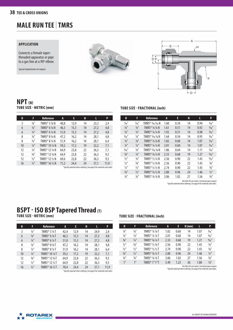
A
E
D P
L
D
F
H
38
ALL RIGHTS OF CHANGE RESERVED
TEE & CROSS UNIONS
TUBE SIZE - FRACTIONAL (inch)
D F Reference A E H L P
1⁄16” 1⁄16” TMRS* 1⁄16 1⁄16 N 1.60 0.34 14 0.94 3⁄16”
1⁄8” 1⁄8” TMRS* 1⁄8 1⁄8 N 1.61 0.51 14 0.92 3⁄32”
1⁄8” ¼” TMRS* 1⁄8 ¼ N 1.92 0.51 14 0.98 3⁄32”
3⁄16” 1⁄8” TMRS* 3⁄16 1⁄8 N 1.64 0.54 14 0.95 3⁄32”
¼” 1⁄8” TMRS* ¼ 1⁄8 N 1.82 0.60 14 1.07 3⁄16”
¼” ¼” TMRS* ¼ ¼ N 2.01 0.60 14 1.07 3⁄16”
5⁄16” 1⁄8” TMRS* 5⁄16 1⁄8 N 1.86 0.64 14 1.11 3⁄16”
3⁄8” ¼” TMRS* 3⁄8 ¼ N 2.33 0.68 19 1.27 9⁄32”
½” ¼” TMRS* ½ ¼ N 2.56 0.90 22 1.43 9⁄32”
½” 3⁄8” TMRS* ½ 3⁄8 N 2.56 0.90 22 1.43 3⁄8”
½” ½” TMRS* ½ ½ N 2.74 0.90 22 1.43 3⁄8”
5⁄8” ½” TMRS* 5⁄8 ½ N 2.80 0.96 24 1.46 ½”
¾” ¾” TMRS* ¾ ¾ N 3.06 1.02 27 1.56 5⁄8”Hex flats (H) are metric. Fractional upon request
*Specify material when ordering. See page 8 for materials and codes.
Hex flats (H) are metric. Fractional upon request*Specify material when ordering. See page 8 for materials and codes.
NPT (N)TUBE SIZE - METRIC (mm)
D F Reference A E H L P
3 1⁄8” TMRS* 3 1⁄8 N 40,8 12,9 14 23,3 2,4
6 1⁄8” TMRS* 6 1⁄8 N 46,3 15,3 14 27,2 4,8
6 ¼” TMRS* 6 ¼ N 51,0 15,3 14 27,2 4,8
8 1⁄8” TMRS* 8 1⁄8 N 47,2 16,2 14 28,1 4,8
8 ¼” TMRS* 8 ¼ N 51,9 16,2 14 28,1 6,4
10 ¼” TMRS* 10 ¼ N 59,2 17,2 19 32,2 7,1
12 ¼” TMRS* 12 ¼ N 64,9 22,8 22 36,3 7,1
12 3⁄8” TMRS* 12 3⁄8 N 64,9 22,8 22 36,3 9,5
12 ½” TMRS* 12 ½ N 69,6 22,8 22 36,3 9,5
16 ½” TMRS* 16 ½ N 71,2 24,4 24 37,1 11,9
TUBE SIZE - FRACTIONAL (inch)
D F Reference A E H (mm) L P
¼” 1⁄8” TMRS* ¼ 1⁄8 T 1.82 0.60 14 1.07 3⁄16”
¼” ¼” TMRS* ¼ ¼ T 2.01 0.60 14 1.07 3⁄16”
3⁄8” ¼” TMRS* 3⁄8 ¼ T 2.33 0.68 19 1.27 9⁄32”
½” 3⁄8” TMRS* ½ 3⁄8 T 2.56 0.90 22 1.43 3⁄8”
½” ½” TMRS* ½ ½ T 2.74 0.90 22 1.43 3⁄8”
5⁄8” ½” TMRS* 5⁄8 ½ T 2.80 0.96 24 1.46 ½”
¾” ¾” TMRS* ¾ ¾ T 3.06 1.02 27 1.56 5⁄8”
1” 1” TMRS* 1” 1’’ T 3.49 1.23 36 1.80 7⁄8”
BSPT - ISO BSP Tapered Thread (T)TUBE SIZE - METRIC (mm)
D F Reference A E H L P
3 ¼” TMRS* 3 ¼ T 42,4 12,9 14 24,9 2,4
6 1⁄8” TMRS* 6 1⁄8 T 46,3 15,3 14 27,2 4,8
6 ¼” TMRS* 6 ¼ T 51,0 15,3 14 27,2 4,8
8 1⁄8” TMRS* 8 1⁄8 T 47,2 16,2 14 28,1 4,8
8 ¼” TMRS* 8 ¼ T 51,9 16,2 14 28,1 6,4
10 ¼” TMRS* 10 ¼ T 59,2 17,2 19 32,2 7,1
12 3⁄8” TMRS* 12 3⁄8 T 64,9 22,8 22 36,3 9,5
12 ½” TMRS* 12 ½ T 64,9 22,8 22 36,3 9,5
16 ½” TMRS* 16 ½ T 70,4 24,4 24 37,1 11,9
*Specify material when ordering. See page 8 for materials and codes.
*Specify material when ordering. See page 8 for materials and codes.
MALE RUN TEE | TMRS
APPLICATION
Connects a female taper-threaded apparatus or pipe to a gas line at a 90º elbow.
Special requirements on request
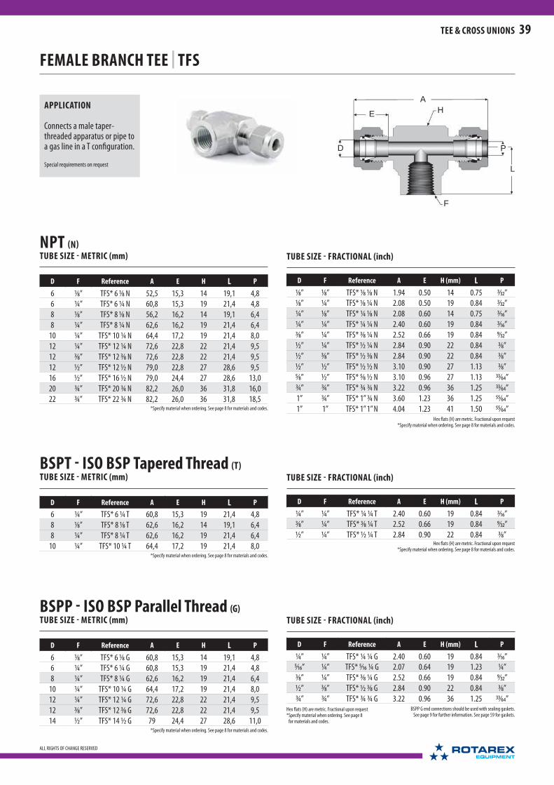
HE
D P
L
A
F
39
ALL RIGHTS OF CHANGE RESERVED
TEE & CROSS UNIONS
TUBE SIZE - FRACTIONAL (inch)
D F Reference A E H (mm) L P
1⁄8” 1⁄8” TFS* 1⁄8 1⁄8 N 1.94 0.50 14 0.75 3⁄32”
1⁄8” ¼” TFS* 1⁄8 ¼ N 2.08 0.50 19 0.84 3⁄32”
¼” 1⁄8” TFS* ¼ 1⁄8 N 2.08 0.60 14 0.75 3⁄16”
¼” ¼” TFS* ¼ ¼ N 2.40 0.60 19 0.84 3⁄16”
3⁄8” ¼” TFS* 3⁄8 ¼ N 2.52 0.66 19 0.84 9⁄32”
½” ¼” TFS* ½ ¼ N 2.84 0.90 22 0.84 3⁄8”
½” 3⁄8” TFS* ½ 3⁄8 N 2.84 0.90 22 0.84 3⁄8”
½” ½” TFS* ½ ½ N 3.10 0.90 27 1.13 3⁄8”
5⁄8” ½” TFS* 5⁄8 ½ N 3.10 0.96 27 1.13 33⁄64”
¾” ¾” TFS* ¾ ¾ N 3.22 0.96 36 1.25 33⁄64”
1” ¾” TFS* 1” ¾ N 3.60 1.23 36 1.25 55⁄64”
1” 1” TFS* 1” 1’’ N 4.04 1.23 41 1.50 55⁄64”
TUBE SIZE - FRACTIONAL (inch)
D F Reference A E H (mm) L P
¼” ¼” TFS* ¼ ¼ G 2.40 0.60 19 0.84 3⁄16”
5⁄16” ¼” TFS* 5⁄16 ¼ G 2.07 0.64 19 1.23 ¼”
3⁄8” ¼” TFS* 3⁄8 ¼ G 2.52 0.66 19 0.84 9⁄32”
½” 3⁄8” TFS* ½ 3⁄8 G 2.84 0.90 22 0.84 3⁄8”
¾” ¾” TFS* ¾ ¾ G 3.22 0.96 36 1.25 33⁄64”BSPP G end connections should be used with sealing gaskets.
See page 9 for further information. See page 59 for gaskets.Hex flats (H) are metric. Fractional upon request* Specify material when ordering. See page 8
for materials and codes.
Hex flats (H) are metric. Fractional upon request*Specify material when ordering. See page 8 for materials and codes.
Hex flats (H) are metric. Fractional upon request*Specify material when ordering. See page 8 for materials and codes.
*Specify material when ordering. See page 8 for materials and codes.
*Specify material when ordering. See page 8 for materials and codes.
*Specify material when ordering. See page 8 for materials and codes.
FEMALE BRANCH TEE | TFS
APPLICATION
Connects a male taper-threaded apparatus or pipe to a gas line in a T configuration.
Special requirements on request
NPT (N)TUBE SIZE - METRIC (mm)
D F Reference A E H L P
6 1⁄8” TFS* 6 1⁄8 N 52,5 15,3 14 19,1 4,8
6 ¼” TFS* 6 ¼ N 60,8 15,3 19 21,4 4,8
8 1⁄8” TFS* 8 1⁄8 N 56,2 16,2 14 19,1 6,4
8 ¼” TFS* 8 ¼ N 62,6 16,2 19 21,4 6,4
10 ¼” TFS* 10 ¼ N 64,4 17,2 19 21,4 8,0
12 ¼” TFS* 12 ¼ N 72,6 22,8 22 21,4 9,5
12 3⁄8” TFS* 12 3⁄8 N 72,6 22,8 22 21,4 9,5
12 ½” TFS* 12 ½ N 79,0 22,8 27 28,6 9,5
16 ½” TFS* 16 ½ N 79,0 24,4 27 28,6 13,0
20 ¾” TFS* 20 ¾ N 82,2 26,0 36 31,8 16,0
22 ¾” TFS* 22 ¾ N 82,2 26,0 36 31,8 18,5
BSPP - ISO BSP Parallel Thread (G)TUBE SIZE - METRIC (mm)
D F Reference A E H L P
6 1⁄8” TFS* 6 1⁄8 G 60,8 15,3 14 19,1 4,8
6 ¼” TFS* 6 ¼ G 60,8 15,3 19 21,4 4,8
8 ¼” TFS* 8 ¼ G 62,6 16,2 19 21,4 6,4
10 ¼” TFS* 10 ¼ G 64,4 17,2 19 21,4 8,0
12 ¼” TFS* 12 ¼ G 72,6 22,8 22 21,4 9,5
12 3⁄8” TFS* 12 3⁄8 G 72,6 22,8 22 21,4 9,5
14 ½” TFS* 14 ½ G 79 24,4 27 28,6 11,0
TUBE SIZE - FRACTIONAL (inch)
D F Reference A E H (mm) L P
¼” ¼” TFS* ¼ ¼ T 2.40 0.60 19 0.84 3⁄16”
3⁄8” ¼” TFS* 3⁄8 ¼ T 2.52 0.66 19 0.84 9⁄32”
½” ¼” TFS* ½ ¼ T 2.84 0.90 22 0.84 3⁄8”
BSPT - ISO BSP Tapered Thread (T)TUBE SIZE - METRIC (mm)
D F Reference A E H L P
6 ¼” TFS* 6 ¼ T 60,8 15,3 19 21,4 4,8
8 1⁄8” TFS* 8 1⁄8 T 62,6 16,2 14 19,1 6,4
8 ¼” TFS* 8 ¼ T 62,6 16,2 19 21,4 6,4
10 ¼” TFS* 10 ¼ T 64,4 17,2 19 21,4 8,0

A
E H
L
D
PF
D
40
ALL RIGHTS OF CHANGE RESERVED
TEE & CROSS UNIONS
BSPP - ISO BSP Parallel Thread (G)TUBE SIZE - METRIC (mm)
D F Reference A E H P L
6 1⁄8” TFRS* 6 1⁄8 G 54,4 15,3 14 4,8 19,1
10 ¼” TFRS* 10 ¼ G 67,4 17,2 19 7,1 21,4
22 ¾” TFRS* 22 ¾ G 82,2 26,0 36 18,5 31,8BSPP G end connections should be used with sealing gaskets.
See page 9 for further information. See page 59 for gaskets.*Specify material when ordering. See page 8 for materials and codes.
TUBE SIZE - FRACTIONAL (inch)
D F Reference A E H(mm) L P
1⁄16” 1⁄16” TFRS* 1⁄16 1⁄16 N 1.48 0.34 12 0.92 3⁄16”
1⁄8” 1⁄8” TFRS* 1⁄8 1⁄8 N 1.72 0.50 14 0.97 3⁄32”
3⁄16” 1⁄8” TFRS* 3⁄16 1⁄8 N 1.75 0.54 14 1,00 1⁄8”
¼” 1⁄8” TFRS* ¼ 1⁄8 N 1.82 0.60 14 1.07 3⁄16”
¼” ¼” TFRS* ¼ ¼ N 2.04 0.60 19 1.2 3⁄16”
3⁄8” ¼” TFRS* 3⁄8 ¼ N 2.16 0.66 19 1.32 9⁄32”
½” 3⁄8” TFRS* ½ 3⁄8 N 2.26 0.90 22 1.42 3⁄8”
½” ½” TFRS* ½ ½ N 2.68 0.90 27 1.55 3⁄8”
¾” ¾” TFRS* ¾ ¾ N 2.86 0.96 36 1.61 5⁄8”
1” ¾” TFRS* 1” ¾ N 3.04 1.23 36 1.79 7⁄8”
1” 1” TFRS* 1” 1’’ N 3.54 1.23 41 2.04 7⁄8”
TUBE SIZE - FRACTIONAL (inch)
D F Reference A E H(mm) L P
¼” 1⁄8” TFRS* ¼ 1⁄8 T 1.82 0.60 14 1.07 3⁄16”
¼” ¼” TFRS* ¼ ¼ T 2.04 0.60 19 1.2 3⁄16”
3⁄8” ¼” TFRS* 3⁄8 ¼ T 2.16 0.66 19 1.32 9⁄32”
½” 3⁄8” TFRS* ½ 3⁄8 T 2.26 0.90 22 1.42 3⁄8”
½” ½” TFRS* ½ ½ T 2.68 0.90 27 1.55 3⁄8”
5⁄8” ½” TFRS* 5⁄8 ½ T 2.68 0.96 27 1.55 33⁄64”
¾” ¾” TFRS* ¾ ¾ T 2.86 0.96 36 1.61 5⁄8”
1” 1” TFRS* 1” 1’’ T 3.54 1.23 41 2.04 7⁄8”
BSPTTUBE SIZE - METRIC (mm)
D F Reference A E H L P
6 1⁄8” TFRS* 6 1⁄8 T 54,4 15,3 14 19,1 4,8
6 ¼” TFRS* 6 ¼ T 60,8 15,3 19 21,4 4,8
8 1⁄8” TFRS* 8 1⁄8 T 56,2 16,2 14 19,1 6,4
8 ¼” TFRS* 8 ¼ T 62,6 16,2 19 21,4 6,4
10 ¼” TFRS* 10 ¼ T 67,4 17,2 19 21,4 7,1
12 3⁄8” TFRS* 12 3⁄8 T 72,6 22,8 22 21,4 9,5
12 ½” TFRS* 12 ½ T 79,0 22,8 27 21,4 9,5
Hex flats (H) are metric. Fractional upon request*Specify material when ordering. See page 8 for materials and codes.
Hex flats (H) are metric. Fractional upon request*Specify material when ordering. See page 8 for materials and codes.
*Specify material when ordering. See page 8 for materials and codes.
*Specify material when ordering. See page 8 for materials and codes.
FEMALE RUN TEE | TFRS
APPLICATION
Connects a male taper-threaded apparatus or pipe to a gas line at a 90º elbow.
Special requirements on request
NPT (N)TUBE SIZE - METRIC (mm)
D F Reference A E H L P
6 1⁄8” TFRS* 6 1⁄8 N 54,4 15,3 14 19,1 4,8
6 ¼” TFRS* 6 ¼ N 60,8 15,3 19 21,4 4,8
8 1⁄8” TFRS* 8 1⁄8 N 56,2 16,2 14 19,1 6,4
8 ¼” TFRS* 8 ¼ N 62,6 16,2 19 21,4 6,4
10 ¼” TFRS* 10 ¼ N 67,4 17,2 19 21,4 7,1
12 ¼” TFRS* 12 ¼ N 72,6 22,8 22 21,4 9,5
12 3⁄8” TFRS* 12 3⁄8 N 72,6 22,8 22 21,4 9,5
12 ½” TFRS* 12 ½ N 79,0 22,8 27 28,6 9,5
16 ½” TFRS* 16 ½ N 79,0 24,4 27 28,6 13,0

A
ED P
D
H
41
ALL RIGHTS OF CHANGE RESERVED
TEE & CROSS UNIONS
CROSS | CS
APPLICATION
Connects tubes of the same dimension in a cross configuration.
Special requirements on request
TUBE SIZE - METRIC (mm)
D Reference A E H P
3 CS* 3 46,5 12,9 12 2,4
4 CS* 4 48,1 13,7 12 3,2
6 CS* 6 54,4 15,3 14 4,8
8 CS* 8 56,2 16,2 14 6,4
10 CS* 10 65,2 17,2 19 7,9
12 CS* 12 72,6 22,8 22 9,5
14 CS* 14 74,2 24,4 24 11,1
16 CS* 16 74,2 24,4 24 12,7
18 CS* 18 79,0 24,4 27 15,1
20 CS* 20 83,7 26,0 30 15,9
22 CS* 22 82,1 26,0 30 19,1
25 CS* 25 91,1 31,3 36 22,2
TUBE SIZE - FRACTIONAL (inch)
D Reference A E H (mm) P
1⁄16” CS* 1⁄16 1.40 0.34 12 3⁄64”
1⁄8” CS* 1⁄8 1.84 0.51 12 3⁄32”
¼” CS* ¼ 2.04 0.60 14 3⁄16”
5⁄16” CS* 5⁄16 2.22 0.64 14 ¼”
3⁄8” CS* 3⁄8 2.26 0.68 19 9⁄32”
½” CS* ½ 2.74 0.90 22 3⁄8”
¾” CS* ¾ 3.12 0.96 27 5⁄8”
1” CS* 1’’ 3.60 1.23 36 7⁄8”Hex flats (H) are metric. Fractional upon request
*Specify material when ordering. See page 8 for materials and codes.
*Specify material when ordering. See page 8 for materials and codes.
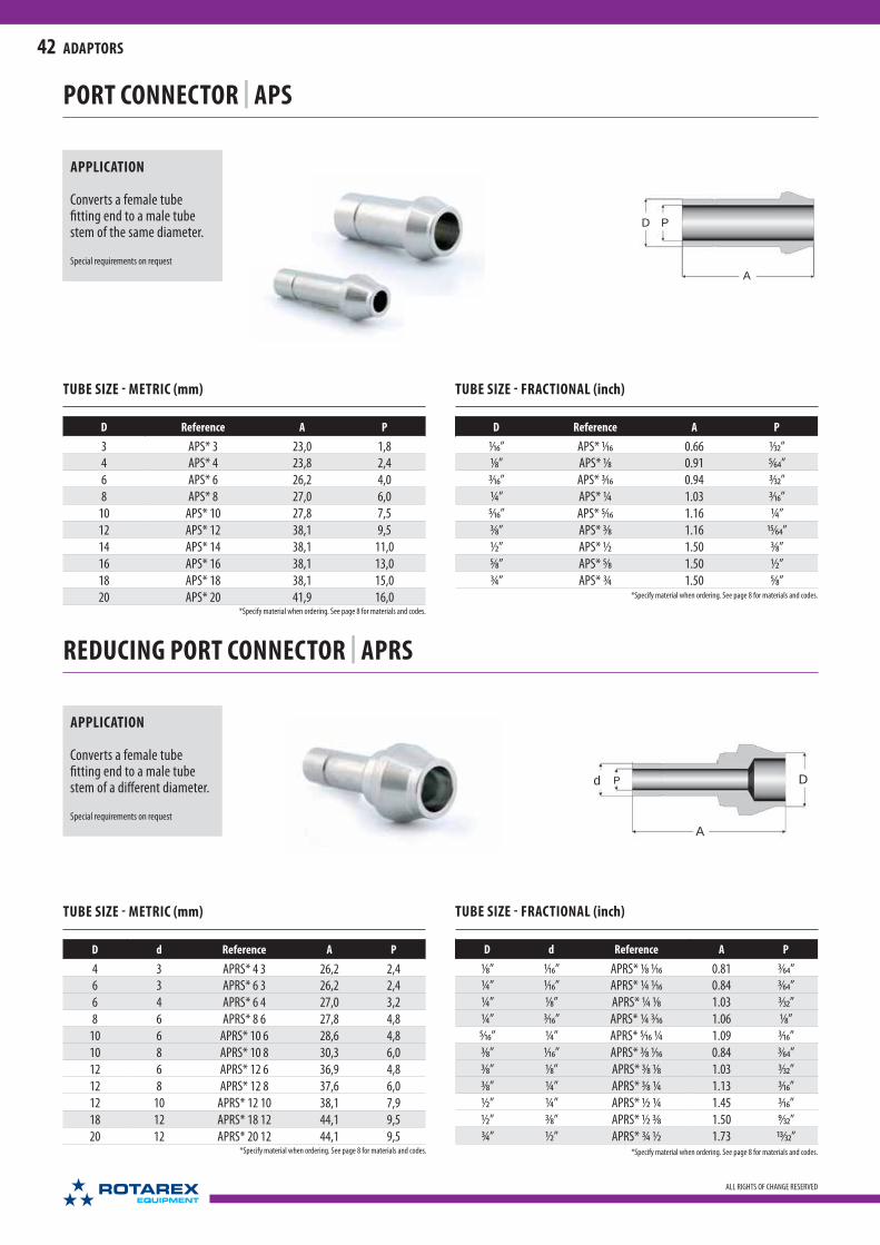
D P
A
DPd
A
42
ALL RIGHTS OF CHANGE RESERVED
ADAPTORS
PORT CONNECTOR | APS
TUBE SIZE - METRIC (mm)
D Reference A P
3 APS* 3 23,0 1,8
4 APS* 4 23,8 2,4
6 APS* 6 26,2 4,0
8 APS* 8 27,0 6,0
10 APS* 10 27,8 7,5
12 APS* 12 38,1 9,5
14 APS* 14 38,1 11,0
16 APS* 16 38,1 13,0
18 APS* 18 38,1 15,0
20 APS* 20 41,9 16,0
TUBE SIZE - FRACTIONAL (inch)
D Reference A P
1⁄16” APS* 1⁄16 0.66 1⁄32”
1⁄8” APS* 1⁄8 0.91 5⁄64”
3⁄16” APS* 3⁄16 0.94 3⁄32”
¼ ” APS* ¼ 1.03 3⁄16”
5⁄16” APS* 5⁄16 1.16 ¼ ”
3⁄8” APS* 3⁄8 1.16 15⁄64”
½ ” APS* ½ 1.50 3⁄8”
5⁄8” APS* 5⁄8 1.50 ½ ”
¾ ” APS* ¾ 1.50 5⁄8”
APPLICATION
Converts a female tube fi tting end to a male tube stem of the same diameter.
Special requirements on request
*Specify material when ordering. See page 8 for materials and codes.
*Specify material when ordering. See page 8 for materials and codes.
REDUCING PORT CONNECTOR | APRS
*Specify material when ordering. See page 8 for materials and codes.
TUBE SIZE - METRIC (mm)
D d Reference A P
4 3 APRS* 4 3 26,2 2,4
6 3 APRS* 6 3 26,2 2,4
6 4 APRS* 6 4 27,0 3,2
8 6 APRS* 8 6 27,8 4,8
10 6 APRS* 10 6 28,6 4,8
10 8 APRS* 10 8 30,3 6,0
12 6 APRS* 12 6 36,9 4,8
12 8 APRS* 12 8 37,6 6,0
12 10 APRS* 12 10 38,1 7,9
18 12 APRS* 18 12 44,1 9,5
20 12 APRS* 20 12 44,1 9,5
TUBE SIZE - FRACTIONAL (inch)
D d Reference A P
1⁄8” 1⁄16” APRS* 1⁄8 1⁄16 0.81 3⁄64”
¼ ” 1⁄16” APRS* ¼ 1⁄16 0.84 3⁄64”
¼ ” 1⁄8” APRS* ¼ 1⁄8 1.03 3⁄32”
¼ ” 3⁄16” APRS* ¼ 3⁄16 1.06 1⁄8”
5⁄16” ¼ ” APRS* 5⁄16 ¼ 1.09 3⁄16”
3⁄8” 1⁄16” APRS* 3⁄8 1⁄16 0.84 3⁄64”
3⁄8” 1⁄8” APRS* 3⁄8 1⁄8 1.03 3⁄32”
3⁄8” ¼ ” APRS* 3⁄8 ¼ 1.13 3⁄16”
½ ” ¼ ” APRS* ½ ¼ 1.45 3⁄16”
½ ” 3⁄8” APRS* ½ 3⁄8 1.50 9⁄32”
¾ ” ½ ” APRS* ¾ ½ 1.73 13⁄32”
APPLICATION
Converts a female tube fi tting end to a male tube stem of a diff erent diameter.
Special requirements on request
*Specify material when ordering. See page 8 for materials and codes.

A
E
H
D
P
d
43
ALL RIGHTS OF CHANGE RESERVED
ADAPTORS
APPLICATION
Converts a tube of one diameter to a tube stem of a larger or smaller diameter.
Special requirements on request
Same as the ADRS with a straight bore-through to accommodate heat exchanger and sensor apparatus.
Special requirements on request
Hex flats (H) are metric. Fractional upon request*Specify material when ordering. See page 8 for materials and codes.
TUBE SIZE - METRIC (mm)
d D Reference A E H P
3 4 ADRS* 3 4 34,4 12,9 8 2,0
3 6 ADRS* 3 6 36,1 12,9 8 2,0
3 8 ADRS* 3 8 36,8 12,9 12 2,0
3 10 ADRS* 3 10 37,6 12,9 12 2,0
4 6 ADRS* 4 6 36,8 13,7 12 3,0
4 8 ADRS* 4 8 37,6 13,7 12 3,0
6 3 ADRS* 6 3 36,8 15,3 14 1,8
6 4 ADRS* 6 4 37,6 15,3 14 2,4
6 6 ADRS* 6 6 39,2 15,3 14 4,0
6 8 ADRS* 6 8 40,1 15,3 14 4,0
6 10 ADRS* 6 10 40,7 15,3 14 4,5
6 12 ADRS* 6 12 46,3 15,3 14 4,5
8 6 ADRS* 8 6 40,4 16,2 14 4,0
8 10 ADRS* 8 10 42,0 16,2 14 6,4
8 12 ADRS* 8 12 47,6 16,2 14 9,5
10 6 ADRS* 10 6 42,4 17,2 17 4,0
10 8 ADRS* 10 8 42,5 17,2 17 6,0
10 12 ADRS* 10 12 48,9 17,2 17 8,0
10 18 ADRS* 10 18 51,3 17,2 22 8,0
10 22 ADRS* 10 22 52,1 17,2 24 8,0
12 6 ADRS* 12 6 45,0 22,8 22 4,0
12 10 ADRS* 12 10 46,6 22,8 22 7,5
12 16 ADRS* 12 16 53,8 22,8 22 9,5
12 18 ADRS* 12 18 53,8 22,8 22 9,5
12 25 ADRS* 12 25 60,1 22,8 24 9,5
16 12 ADRS* 16 12 53,0 24,4 24 13,0
16 18 ADRS* 16 18 54,6 24,4 24 13,0
18 12 ADRS* 18 12 55,4 24,4 27 9,5
18 16 ADRS* 18 16 56,9 24,4 27 13,0
18 22 ADRS* 18 22 56,9 24,4 27 15,0
18 25 ADRS* 18 25 64,1 24,4 27 15,0
22 20 ADRS* 22 20 61.7 24,4 30 19.1
22 25 ADRS* 22 25 64.9 24,4 30 19,1
REDUCER | ADRS
TUBE SIZE - FRACTIONAL (inch)
d D Reference A E H (mm) P
1⁄16” 1⁄8” ADRS* 1⁄16” 1⁄8” 1.10 0.34 8 1⁄16”
1⁄8” 1⁄8” ADRS* 1⁄8” 1⁄8” 1.29 0.50 8 1⁄16”
1⁄8” 3⁄16” ADRS* 1⁄8” 3⁄16” 1.32 0.50 8 5⁄64”
1⁄8” ¼” ADRS* 1⁄8” ¼” 1.39 0.50 8 5⁄64”
3⁄16” 1⁄8” ADRS* 3⁄16” 1⁄8” 1.31 0.54 12 1⁄16”
3⁄16” ¼” ADRS* 3⁄16” ¼” 1.41 0.54 12 1⁄8”
¼” 1⁄8” ADRS* ¼” 1⁄8” 1.41 0.60 14 1⁄16”
¼” 3⁄16” ADRS* ¼” 3⁄16” 1.44 0.60 14 3⁄16”
¼” ¼” ADRS* ¼” ¼” 1.50 0.60 14 5⁄32”
¼” 5⁄16” ADRS* ¼” 5⁄16” 1.54 0.60 14 3⁄16”
¼” 3⁄8” ADRS* ¼” 3⁄8” 1.57 0.60 14 3⁄16”
¼” ½ ” ADRS* ¼” ½” 1.79 0.60 14 3⁄16”
¼” ¾” ADRS* ¼” ¾” 1.97 0.60 22 3⁄16”
¼” 5⁄8” ADRS* ¼” 5⁄8” 1.89 0.60 17 3⁄16”
5⁄16” 3⁄8” ADRS* 5⁄16” 3⁄8” 1.58 0.64 14 ¼”
5⁄16” ½” ADRS* 5⁄16” ½” 1.80 0.64 14 ¼”
3⁄8” ¼” ADRS* 3⁄8” ¼” 1.59 0.66 17 5⁄32”
3⁄8” 3⁄8” ADRS* 3⁄8” 3⁄8” 1.65 0.66 17 9⁄32”
3⁄8” ½” ADRS* 3⁄8” ½” 1.87 0.66 17 9⁄32”
3⁄8” 5⁄8” ADRS* 3⁄8” 5⁄8” 1.94 0.66 19 9⁄32”
3⁄8” ¾” ADRS* 3⁄8” ¾” 2.02 0.66 22 9⁄32”
½” ¼” ADRS* ½” ¼” 1.78 0.90 22 5⁄32”
½” 3⁄8” ADRS* ½” 3⁄8” 1.83 0.90 22 9⁄32”
½” ½” ADRS* ½” ½” 1.96 0.90 22 3⁄8”
½” 5⁄8” ADRS* ½” 5⁄8” 2.13 0.90 22 3⁄8”
½” ¾” ADRS* ½” ¾” 2.13 0.90 22 3⁄8”
5⁄8” 3⁄8” ADRS* 5⁄8” 3⁄8” 1.88 0.96 24 9⁄32”
5⁄8” ½” ADRS* 5⁄8” ½” 2.10 0.96 24 3⁄8”
5⁄8” ¾” ADRS* 5⁄8” ¾” 2.16 0.96 24 ½”
5⁄8” 7⁄8” ADRS* 5⁄8” 7⁄8” 2.29 0.96 24 ½”
5⁄8” 1” ADRS* 5⁄8” 1” 2.45 0.96 27 ½”
¾” ½” ADRS* ¾” ½” 2.14 0.96 27 3⁄8”
¾” 1” ADRS* ¾” 1” 2.48 0.96 27 5⁄8”
HEAT EXCHANGER REDUCER | ADTS
For ordering use ADTS instead of ADRS
*Specify material when ordering. See page 8 for materials and codes.

A
E
D
H
P D
44
ALL RIGHTS OF CHANGE RESERVED
ADAPTORS
APPLICATION
Converts a metric tube to a fractional tube stem or vice-versa.
Special requirements on request
CONVERTING REDUCER | AMOD
Hex flats (H) are metric. Fractional upon request*Specify material when ordering. See page 8 for materials and codes.
Hex flats (H) are metric. Fractional upon request*Specify material when ordering. See page 8 for materials and codes.
TUBE SIZE - METRIC TO FRACTIONAL - (mm)
D d Reference A E H P
1⁄8” 3 AMOD* 3 1⁄8 33,6 12,9 12 2,4
¼” 3 AMOD* 3 ¼ 34,4 12,9 12 2,4
¼” 4 AMOD* 4 ¼ 36,8 13,7 12 3,2
1⁄8” 6 AMOD* 6 1⁄8 36,8 15,3 14 4,8
¼” 6 AMOD* 6 ¼ 37,6 15,3 14 4,8
5⁄16” 6 AMOD* 6 5⁄16 40,2 15,3 14 4,8
3⁄8” 6 AMOD* 6 3⁄8 40,7 15,3 14 4,8
½” 6 AMOD* 6 ½ 46,3 15,3 14 4,8
3⁄8” 8 AMOD* 8 3⁄8 42,0 16,2 14 7,9
½” 8 AMOD* 8 ½ 47,6 16,2 14 7,9
3⁄8” 10 AMOD* 10 3⁄8 43,1 17,2 17 7,9
½” 10 AMOD* 10 ½ 48,9 17,2 17 7,9
½” 12 AMOD* 12 ½ 52,2 22,8 22 9,5
¾” 12 AMOD* 12 ¾ 53,8 22,8 22 9,5
¾” 18 AMOD* 18 ¾ 56,1 24,4 27 12,7
1” 18 AMOD* 18 1” 62,4 24,4 27 12,7
1” 25 AMOD* 25 1” 70,1 31,3 36 19,1
TUBE SIZE - FRACTIONAL TO METRIC - (inch)
d D Reference A E H (mm) P
1⁄8” 6 AMOD* 1⁄8 6 1.46 0.5 8 2.4
*Specify material when ordering. See page 8 for materials and codes.
APPLICATION
Converts a tube fitting end to a tube stem through a wall panel. The tube stem is useful to set the direction through a panel construction.
Special requirements on request
TUBE SIZE - METRIC (mm)
D Reference A E H PB’Head Hole
Drill Size
MA. B’Head
Thick.
3 UCAS* 3 50,2 12,9 14 1,8 8,3 12,7
4 UCAS* 4 51,9 13,7 14 2,4 9,8 12,7
6 UCAS* 6 55,8 15,3 17 4,8 11,5 10,3
8 UCAS* 8 59,1 16,2 17 6,4 13,1 11,1
10 UCAS* 10 61,6 17,2 22 7,5 16,3 11,1
12 UCAS* 12 72,8 22,8 24 9,5 19,5 12,7
14 UCAS* 14 75,2 24,4 27 11,0 21,0 12,7
16 UCAS* 16 76,8 24,4 27 12,7 22,5 12,7
18 UCAS* 18 83,1 24,4 30 12,7 26,0 16,7
20 UCAS* 20 83,9 26,0 32 15,9 29,0 19,1
22 UCAS* 22 90,3 26,0 36 18,5 29,0 20,6
25 UCAS* 25 101,1 31,3 38 22,0 33,8 23,8
TUBE SIZE - FRACTIONAL (inch)
D Reference A E H (mm) PB’Head Hole
Drill SizeMA. B’Head
Thick.
1⁄8” UCAS* 1⁄8 1.98 0.50 14 1⁄32” 21⁄64” ½”
¼” UCAS* ¼ 2.20 0.60 17 3⁄16” 29⁄64” 17⁄32”
3⁄8” UCAS* 3⁄8 2.42 0.66 22 9⁄32” 37⁄64” 9⁄16”
½” UCAS* ½ 2.86 0.90 24 3⁄8” 49⁄64” 19⁄32”
5⁄8” UCAS* 5⁄8 3.02 0.96 27 ½” 57⁄64” 19⁄32”
¾” UCAS* ¾ 3.27 0.96 30 5⁄8” 1 1⁄64” 25⁄32”
1” UCAS* 1” 3.98 1.23 38 7⁄8” 1 21⁄64” 15⁄16”
*Specify material when ordering. See page 8 for materials and codes.
BULKHEAD REDUCER | UCAS

A
D P
F
H
45
ALL RIGHTS OF CHANGE RESERVED
ADAPTORS
MALE ADAPTOR | ADS
NPT (N)TUBE SIZE - METRIC (mm)
D F Reference A H P
4 1⁄8” ADS* 4 1⁄8 N 28,6 12 3,2
4 ¼” ADS* 4 ¼ N 34,1 14 3,2
6 1⁄8” ADS* 6 1⁄8 N 31,0 14 4,8
6 ¼” ADS* 6 ¼ N 35,7 14 4,8
6 3⁄8” ADS* 6 3⁄8 N 36,5 19 4,8
6 ½” ADS* 6 ½ N 42,1 22 4,8
8 1⁄8” ADS* 8 1⁄8 N 31,8 14 4,8
8 ¼” ADS* 8 ¼ N 37,3 14 6,4
8 3⁄8” ADS* 8 3⁄8 N 37,3 19 6,4
10 1⁄8” ADS* 10 1⁄8 N 33,3 17 4,8
10 ¼” ADS* 10 ¼ N 38,1 17 7,9
10 3⁄8” ADS* 10 3⁄8 N 38,1 19 7,9
10 ½” ADS* 10 ½ N 43,7 22 7,9
12 ¼” ADS* 12 ¼ N 42,9 14 7,1
12 3⁄8” ADS* 12 3⁄8 N 43,7 19 9,5
12 ½” ADS* 12 ½ N 49,2 22 9,5
14 3⁄8” ADS* 14 3⁄8 N 45,2 19 7,1
16 3⁄8” ADS* 16 3⁄8 N 45,2 19 9,5
16 ½” ADS* 16 ½ N 50,8 22 11,9
16 ¾” ADS* 16 ¾ N 50,8 27 12,7
20 ¾” ADS* 20 ¾ N 54,0 27 15,9
22 ¾” ADS* 22 ¾ N 54,0 27 15,9
25 ¾” ADS* 25 ¾*** 60,3 27 15,9
TUBE SIZE - FRACTIONAL (inch)
D F Reference A H (mm) P
1⁄8” 1⁄8” ADS* 1⁄8 1⁄8 N 1.16 12 3⁄32”
1⁄8” ¼” ADS* 1⁄8 ¼ N 1.38 14 3⁄32”
3⁄16” 1⁄8” ADS* 3⁄16 1⁄8 N 1.19 12 1⁄8”
3⁄16” ¼” ADS* 3⁄16 ¼ N 1.41 14 1⁄8”
¼” 1⁄8” ADS* ¼ 1⁄8 N 1.25 14 3⁄16”
¼” ¼” ADS* ¼ ¼ N 1.47 14 3⁄16”
¼” 3⁄8” ADS* ¼ 3⁄8 N 1.97 19 3⁄16”
¼” ½” ADS* ¼ ½ N 1.70 22 3⁄16”
5⁄16” 1⁄8” ADS* 5⁄16 1⁄8 N 1.30 14 3⁄16”
5⁄16” ¼” ADS* 5⁄16 ¼ N 1.50 14 ¼”
5⁄16” 3⁄8” ADS* 5⁄16 3⁄8 N 1.44 14 ¼
3⁄8” 1⁄8” ADS* 3⁄8 1⁄8 N 1.33 17 3⁄16”
3⁄8” ¼” ADS* 3⁄8 ¼ N 1.53 17 9⁄32”
3⁄8” 3⁄8” ADS* 3⁄8 3⁄8 N 1.56 19 9⁄32”
3⁄8” ½” ADS* 3⁄8 ½ N 1.78 22 9⁄32”
½” ¼” ADS* ½ ¼ N 1.75 14 9⁄32”
½” 3⁄8” ADS* ½ 3⁄8 N 1.78 19 3⁄8”
½” ½” ADS* ½ ½ N 2.00 22 13⁄32”
5⁄8” ½” ADS* 5⁄8 ½ N 2.06 22 15⁄32”
¾” ½” ADS* ¾ ½ N 2.06 22 15⁄32”
¾” ¾” ADS* ¾ ¾ N 2.06 27 5⁄8”
1” ¾” ADS* 1” ¾ N 2.31 36 5⁄8”
1” 1” ADS* 1” 1” N 2.61 36 7⁄8”Hex flats (H) are metric. Fractional upon request
*Specify material when ordering. See page 8 for materials and codes.
*Specify material when ordering. See page 8 for materials and codes.
APPLICATION
Converts a female tapered-thread (NPT) end to a tube stem.
Special requirements on request

A
D P
F
H
46
ALL RIGHTS OF CHANGE RESERVED
ADAPTORS
MALE ADAPTOR | ADS
BSPT - ISO BSP Tapered Thread (T)TUBE SIZE - METRIC (mm)
D F Reference A H P
3 1⁄8” ADS* 3 1⁄8 T 27,8 12 2,4
3 ¼” ADS* 3 ¼ T 33,3 14 2,4
4 1⁄8” ADS* 4 1⁄8 T 28,6 12 3,2
4 ¼” ADS* 4 ¼ T 34,1 14 3,2
6 1⁄8” ADS* 6 1⁄8 T 31,0 14 4,8
6 ¼” ADS* 6 ¼ T 35,7 14 4,8
6 3⁄8” ADS* 6 3⁄8 T 36,5 19 4,8
8 1⁄8” ADS* 8 1⁄8 T 31,8 14 4,8
8 ¼” ADS* 8 ¼ T 37,3 14 6,4
8 3⁄8” ADS* 8 3⁄8 T 37,3 19 6,4
10 1⁄8” ADS* 10 1⁄8 T 33,3 17 4,8
10 ¼” ADS* 10 ¼ T 38,1 17 7,9
10 3⁄8” ADS* 10 3⁄8 T 38,1 19 7,9
10 ½” ADS* 10 ½ T 43,7 22 7,9
12 ¼” ADS* 12 ¼ T 42,9 14 7,1
12 3⁄8” ADS* 12 3⁄8 T 43,7 19 9,5
12 ½” ADS* 12 ½ T 49,2 22 9,5
14 3⁄8” ADS* 14 3⁄8 T 45,2 19 7,1
16 3⁄8” ADS* 16 3⁄8 T 45,2 19 9,5
16 ½” ADS* 16 ½ T 50,8 22 11,9
16 ¾” ADS* 16 ¾ T 50,8 27 12,7
20 ½” ADS* 20 ½ T 51,6 22 11,9
20 ¾” ADS* 20 ¾ T 54,0 27 15,9
25 ¾” ADS* 25 ¾ T 60,3 27 15,9
TUBE SIZE - FRACTIONAL (inch)
D F Reference A H (mm) P
1⁄8” 1⁄8” ADS* 1⁄8 1⁄8 T 1.16 12 3⁄32”
1⁄8” ¼” ADS* 1⁄8 ¼ T 1.38 14 3⁄32”
¼” 1⁄8” ADS* ¼ 1⁄8 T 1.25 14 3⁄16”
¼” ¼” ADS* ¼ ¼ T 1.47 14 3⁄16”
¼” 3⁄8” ADS* ¼ 3⁄8 T 1.97 19 3⁄16”
¼” ½” ADS* ¼ ½ T 1.70 22 3⁄16”
5⁄16” ¼” ADS* 5⁄16 ¼ T 1.50 14 ¼”
3⁄8” ¼” ADS* 3⁄8 ¼ T 1.53 17 9⁄32”
3⁄8” 3⁄8” ADS* 3⁄8 3⁄8 T 1.56 19 9⁄32”
3⁄8” ½” ADS* 3⁄8 ½ T 1.78 22 9⁄32”
½” ¼” ADS* ½ ¼ T 1.75 14 9⁄32”
½” 3⁄8” ADS* ½ 3⁄8 T 1.78 19 3⁄8”
½” ½” ADS* ½ ½ T 2.00 22 13⁄32”
¾” ¾” ADS* ¾ ¾ T 2.06 27 5⁄8”
1” 1” ADS* 1” 1” T 2.61 36 7⁄8”
APPLICATION
Converts a female tapered-thread (BSPT) end to a tube stem.
Special requirements on request
Hex flats (H) are metric. Fractional upon request*Specify material when ordering. See page 8 for materials and codes.
*Specify material when ordering. See page 8 for materials and codes.

A
PD
F
H
47
ALL RIGHTS OF CHANGE RESERVED
ADAPTORS
MALE ADAPTOR | ADS
BSPP - ISO BSP Parallel Thread (G) TUBE SIZE - METRIC (mm)
D F Reference A H P
3 1⁄8” ADS* 3 1⁄8 G 31,0 14 1,8
3 ¼” ADS* 3 ¼ G 35,7 19 1,8
4 1⁄8” ADS* 4 1⁄8 G 31,8 14 2,4
6 1⁄8” ADS* 6 1⁄8 G 33,3 14 4,8
6 ¼” ADS* 6 ¼ G 38,1 19 4,8
6 3⁄8” ADS* 6 3⁄8 G 38,9 22 4,0
8 1⁄8” ADS* 8 1⁄8 G 34,2 14 4,0
8 ¼” ADS* 8 ¼ G 38,9 19 6,0
8 3⁄8” ADS* 8 3⁄8 G 39,7 22 6,0
8 ½” ADS* 8 ½ G 43,7 27 6,0
10 ¼” ADS* 10 ¼ G 39,7 19 6,0
10 3⁄8” ADS* 10 3⁄8 G 40,5 22 7,1
10 ½” ADS* 10 ½ G 43,7 27 7,1
12 ¼” ADS* 12 ¼ G 45,3 19 6,0
12 3⁄8” ADS* 12 3⁄8 G 46,0 22 7,9
12 ½” ADS* 12 ½ G 49,2 27 9,5
16 ¾” ADS* 16 ¾ G 54,8 36 13,0
TUBE SIZE - FRACTIONAL (inch)
D F Reference A H (mm) P
1⁄8” 1⁄8” ADS* 1⁄8 1⁄8 G 1.53 14 1⁄16”
1⁄8” ¼” ADS* 1⁄8 ¼ G 1.11 19 1⁄16”
¼” 1⁄8” ADS* ¼ 1⁄8 G 1.25 14 3⁄32”
¼” ¼” ADS* ¼ ¼ G 1.50 19 3⁄32”
¼” 3⁄8” ADS* ¼ 3⁄8 G 1.50 22 3⁄32"
3⁄8” ¼” ADS* 3⁄8 ¼ G 1.56 19 15⁄64”
3⁄8” 3⁄8” ADS* 3⁄8 3⁄8 G 1.59 22 9⁄32”
½” ¼” ADS* ½ ¼ G 1.78 19 9⁄32”
½” 3⁄8” ADS* ½ 3⁄8 G 1.81 22 3⁄8”
¾” ¾” ADS* ¾ ¾ G 1.78 36 5⁄8”BSPP G end connections should be used with sealing gaskets.
See page 9 for further information. See page 59 for gaskets.
BSPP - ISO BSP Parallel Thread (K)TUBE SIZE - FRACTIONAL (inch)
D F Reference A H P
6 1⁄8” ADS* 6 1⁄8 K 33,3 14 4,8
6 ¼” ADS* 6 ¼ K 38,1 19 4,8
8 ¼” ADS* 8 ¼ K 38,9 19 6
10 ¼” ADS* 10 ¼ K 39,7 19 6
10 3⁄8” ADS* 10 3⁄8 K 40,5 22 7,1
10 ½” ADS* 10 ½ K 43,7 27 7,1
12 ¼” ADS* 12 ¼ K 45,3 19 6
12 3⁄8” ADS* 12 3⁄8 K 46,0 22 7,9
12 ½” ADS* 12 ½ K 49,2 27 9,5
TUBE SIZE - FRACTIONAL (inch)
D F Reference A H (mm) P
¼” 1⁄8” ADS* ¼ 1⁄8 K 1.25 14 3⁄32”
¼” ¼” ADS* ¼ ¼ K 1.50 19 3⁄32”
¼” 3⁄8” ADS* ¼ 3⁄8 K 1.50 22 3⁄32"
¼” ½” ADS* ¼ ½ K 1.66 27 5⁄32"
3⁄8” 1⁄8” ADS* 3⁄8 1⁄8 K 1.38 14 1⁄8"
3⁄8” ¼” ADS* 3⁄8 ¼ K 1.56 19 15⁄64”
3⁄8” ½” ADS* 3⁄8 ½ K 1.72 27 9⁄32”
½” ¼” ADS* ½ ¼ K 1.78 19 9⁄32”
½” 3⁄8” ADS* ½ 3⁄8 K 1.81 22 3⁄8”BSPP K end connections must be used with sealing gaskets. See page 9 for further information. See page 59 for gaskets.
APPLICATION
Converts a female parallel thread (BSPP) end to a tube stem.
Special requirements on request
Hex flats (H) are metric. Fractional upon request* Specify material when ordering. See page 8
for materials and codes.
Hex flats (H) are metric. Fractional upon request* Specify material when ordering. See page 8
for materials and codes.
*Specify material when ordering. See page 8 for materials and codes.
*Specify material when ordering. See page 8 for materials and codes.

A
D P
HF
A
PD
H
F
48
ALL RIGHTS OF CHANGE RESERVED
ADAPTORS
MALE ADAPTOR «AN» | ADS AN
APPLICATION
Converts a female AN thread end to a male tube stem.
Special requirements on request
AN 37 (AN) TUBE SIZE - METRIC (mm)
DAN tube
flare sizeReference A H P F
6 ¼" ADS* 6 ¼ AN 37,3 14 4,8 7⁄16” - 20
10 ¼" ADS* 10 ¼ AN 38,9 14 7,1 7⁄16” - 20
10 3⁄8" ADS* 10 3⁄8 AN 39,7 17 7,1 9⁄16” - 18
12 ½" ADS* 12 ½ AN 48,4 22 9,5 ¾” - 16
18 ¾" ADS* 18 ¾ AN 56,4 27 9,5 1 1⁄16” - 12
25 1" ADS* 25 1” AN 65,5 36 21,4 1 5⁄16” - 12
TUBE SIZE - FRACTIONAL (inch)
DAN tube
flare sizeReference A H (mm) P F
¼” ¼" ADS* ¼ ¼ AN 1 15⁄32” 14 3⁄16” 7⁄16” - 20
3⁄8” ¼" ADS* 3⁄8 ¼ AN 1 17⁄32” 14 9⁄32” 7⁄16” - 20
3⁄8” 3⁄8" ADS* 3⁄8 3⁄8 AN 1 9⁄16” 17 9⁄32” 9⁄16” - 18
½” ½" ADS* ½ ½ AN 1 29⁄32” 22 3⁄8” ¾” - 16¾” ¾" ADS* ¾ ¾ AN 2 7⁄32” 27 3⁄8” 1 1⁄16” - 121” 1" ADS* 1” 1” AN 2 37⁄64” 36 7⁄8” 1 5⁄16” - 12
APPLICATION
Converts a female UN threaded end connection apparatus to a male tube stem.
Special requirements on request
MALE O-RING ADAPTOR «UN» | AOMSS
UN (UN)TUBE SIZE - METRIC (mm)
D F Reference A H P
3 5⁄16” - 24 AOMSS* 3 5⁄16 31,0 14 2,4
4 3⁄8” - 24 AOMSS* 4 3⁄8 32,5 17 3,2
6 7⁄16” - 20 AOMSS* 6 7⁄16 36,5 19 4,8
8 ½” - 20 AOMSS* 8 ½ 38,9 22 6,4
10 9⁄16” - 18 AOMSS* 10 9⁄16 40,5 24 8,0
12 ¾” - 16 AOMSS* 12 ¾ 46,8 30 9,5
16 7⁄8” - 14 AOMSS* 16 7⁄8 50,8 36 13,0
18 1 1⁄16”-12 AOMSS* 18 1 1⁄16 53,2 38 15,0
20 1 1⁄16”-12 AOMSS* 20 1 1⁄16 55,6 38 16,0
22 1 1⁄16”-12 AOMSS* 22 1 1⁄16 55,6 38 18,5
25 1 5⁄16”-12 AOMSS* 25 1 5⁄16 62,7 46 22,0
TUBE SIZE - FRACTIONAL (inch)
D F Reference A H (mm) P
1⁄8” 5⁄16” - 24 AOMSS* 1⁄8 5⁄16 1.22 14 3⁄32”
3⁄16” 3⁄8” - 24 AOMSS* 3⁄16 3⁄8 1.28 17 1⁄8”
¼” 7⁄16” - 20 AOMSS* ¼ 7⁄16 1.44 19 3⁄16”
5⁄16” ½” - 20 AOMSS* 5⁄16 ½ 1.53 22 ¼”
3⁄8” 9⁄16” - 18 AOMSS* 3⁄8 9⁄16 1.59 24 5⁄16”
½” ¾” - 16 AOMSS* ½ ¾ 1.84 30 13⁄32”UN fittings are supplied with sealing O-rings in Nitrile (NBR).
Fluorocarbon (FPM) O-rings are available upon request.See page 8 for additional information.
Hex flats (H) are metric. Fractional upon request*Specify material when ordering. See page 8 for materials and codes.
Hex flats (H) are metric. Fractional upon request* Specify material when ordering. See page 8
for materials and codes.
*Specify material when ordering. See page 8 for materials and codes.
*Specify material when ordering. See page 8 for materials and codes.

A
D P
H
F
49
ALL RIGHTS OF CHANGE RESERVED
ADAPTORS
APPLICATION
Converts a female NPSM threaded end connection apparatus to a male tube stem.
Special requirements on request
MALE O-RING ADAPTOR «NPSM» | AOMS
NPSM (NPSM)TUBE SIZE - METRIC (mm)
D F Reference A H P
6 1⁄8” AOMS* 6 1⁄8 33,3 19 4,8
6 ¼” AOMS* 6 ¼ 36,5 24 4,8
6 3⁄8” AOMS* 6 3⁄8 38,1 30 4,8
10 ¼” AOMS* 10 ¼ 38,1 24 7,1NPSM fittings are supplied with sealing O-rings in Nitrile (NBR). Fluorocarbon (FPM) O-rings are available upon request.
See page 8 for additional information.*Specify material when ordering. See page 8 for materials and codes.
TUBE SIZE - FRACTIONAL (inch)
D F Reference A H (mm) P
1⁄16” 1⁄8” AOMS* 1⁄8 1⁄16 1.03 19 3⁄64”
1⁄8” 1⁄8” AOMS* 1⁄8 1⁄8 1.22 19 3⁄32”
1⁄8” ¼” AOMS* 1⁄8 ¼ 1.34 24 3⁄32”
3⁄16” 1⁄8” AOMS* 3⁄16 1⁄8 1.25 19 1⁄8”
3⁄16” ¼” AOMS* 3⁄16 ¼ 1.38 24 1⁄8”
¼” 1⁄8” AOMS* ¼ 1⁄8 1.31 19 3⁄16”
¼” ¼” AOMS* ¼ ¼ 1.44 24 3⁄16”
¼” 3⁄8” AOMS* ¼ 3⁄8 1.50 30 3⁄16”
5⁄16” 1⁄8” AOMS* 5⁄16 1⁄8 1.34 19 3⁄16”
5⁄16” ¼” AOMS* 5⁄16 ¼ 1.47 24 ¼”
3⁄8” 1⁄8” AOMS* 3⁄8 1⁄8 1.38 19 3⁄16”
3⁄8” ¼” AOMS* 3⁄8 ¼ 1.50 24 9⁄32”
3⁄8” 3⁄8” AOMS* 3⁄8 3⁄8 1.56 30 9⁄32”
½” 3⁄8” AOMS* ½ 3⁄8 1.78 30 13⁄32”
5⁄8” ½” AOMS* 5⁄8 ½ 2.06 36 ½”
¾” ¾” AOMS* ¾ ¾ 2.16 41 5⁄8”
1” 1” AOMS* 1” 1” 2.56 46 7⁄8”
Hex flats (H) are metric. Fractional upon request*Specify material when ordering. See page 8 for materials and codes.

A
H
FD
50
ALL RIGHTS OF CHANGE RESERVED
ADAPTORS
FEMALE ADAPTOR | AFS
APPLICATION
Converts a male tapered-thread (NPT) end to a tube stem.
Special requirements on request
NPT (N)TUBE SIZE - METRIC (mm)
D F Reference A H
3 1⁄8” AFS* 3 1/8 N 27,0 14
3 ¼” AFS* 3 1/4 N 31,8 19
4 1⁄8” AFS* 4 1/8 N 27,8 14
4 ¼” AFS* 4 1/4 N 32,5 19
6 1⁄8” AFS* 6 1/8 N 29,4 14
6 ¼” AFS* 6 1/4 N 34,1 19
6 3⁄8” AFS* 6 3/8 N 35,7 22
6 ½” AFS* 6 1/2 N 40,5 27
8 1⁄8” AFS* 8 1/8 N 30,2 14
8 ¼” AFS* 8 1/4 N 34,9 19
8 3⁄8” AFS* 8 3/8 N 36,5 22
8 ½” AFS* 8 1/2 N 41,3 27
10 1⁄8” AFS* 10 1/8 N 31,0 14
10 ¼” AFS* 10 1/4 N 35,7 19
10 3⁄8” AFS* 10 3/8 N 37,3 22
10 ½” AFS* 10 1/2 N 42,1 27
12 ¼” AFS* 12 1/4 N 41,3 19
12 3⁄8” AFS* 12 3/8 N 42,9 22
12 ½” AFS* 12 1/2 N 47,6 27
14 3⁄8” AFS* 14 3/8 N 44,5 22
14 ½” AFS* 14 1/2 N 49,2 27
14 ¾” AFS* 14 3/4 N 51,6 32
16 3⁄8” AFS* 16 3⁄8 N 44,5 22
16 ½” AFS* 16 ½ N 49,2 27
16 ¾” AFS* 16 ¾ N 51,6 32
18 ½” AFS* 18 ½ N 49,2 27
18 ¾” AFS* 18 ¾ N 51,5 32
18 1” AFS* 18 1” N 60,3 41
22 ¾” AFS* 22 ¾ N 52,4 32
25 ¾” AFS* 25 ¾ N 58,8 32
25 1” AFS* 25 1” N 67,5 41
TUBE SIZE - FRACTIONAL (inch)
D F Reference A H (mm)
1⁄8” 1⁄8” AFS* 1⁄8 1⁄8 N 1.06 14
1⁄8” ¼” AFS* 1⁄8 ¼ N 1.25 19
3⁄16” 1⁄8” AFS* 3⁄16 1⁄8 N 1.09 14
3⁄16” ¼” AFS* 3⁄16 ¼ N 1.28 19
¼” 1⁄8” AFS* ¼ 1⁄8 N 1.16 14
¼” ¼” AFS* ¼ ¼ N 1.34 19
¼” 3⁄8” AFS* ¼ 3⁄8 N 1.41 22
¼” ½” AFS* ¼ ½ N 1.59 27
5⁄16” 1⁄8” AFS* 5⁄16 1⁄8 N 1.19 14
5⁄16” ¼” AFS* 5⁄16 ¼ N 1.38 19
5⁄16” 3⁄8” AFS* 5⁄16 3⁄8 N 1.44 22
5⁄16” ½” AFS* 5⁄16 ½ N 1.63 27
3⁄8” 1⁄8” AFS* 3⁄8 1⁄8 N 1.22 17
3⁄8” ¼” AFS* 3⁄8 ¼ N 1.41 19
3⁄8” 3⁄8” AFS* 3⁄8 3⁄8 N 1.47 22
3⁄8” ½” AFS* 3⁄8 ½ N 1.66 27
½” ¼” AFS* ½ ¼ N 1.63 22
½” 3⁄8” AFS* ½ 3⁄8 N 1.69 22
½” ½” AFS* ½ ½ N 1.88 27
5⁄8” 3⁄8” AFS* 5⁄8 3⁄8 N 1.75 24
5⁄8” ½” AFS* 5⁄8 ½ N 1.94 27
5⁄8” ¾” AFS* 5⁄8 ¾ N 2.03 32
¾” ½” AFS* ¾ ½ N 1.94 27
¾” ¾” AFS* ¾ ¾ N 2.03 32
¾” 1” AFS* ¾ 1” N 2.38 41
7⁄8” ¾” AFS* 7⁄8 ¾ N 2.06 32
1” ¾” AFS* 1” ¾ N 2.31 36
1” 1” AFS* 1” 1” N 2.66 41Hex flats (H) are metric. Fractional upon request
*Specify material when ordering. See page 8 for materials and codes.
*Specify material when ordering. See page 8 for materials and codes.

A
H
FD
51
ALL RIGHTS OF CHANGE RESERVED
ADAPTORS
APPLICATION
Converts a male tapered-thread (BSPT) end to a tube stem.
Special requirements on request
FEMALE ADAPTOR | AFS
BSPT - ISO BSP Tapered Thread (T)TUBE SIZE - METRIC (mm)
D F Reference A H
3 1⁄8” AFS* 3 1/8 T 27,0 14
3 ¼” AFS* 3 1/4 T 31,8 19
4 1⁄8” AFS* 4 1/8 T 27,8 14
4 ¼” AFS* 4 1/4 T 32,5 19
6 1⁄8” AFS* 6 1/8 T 29,4 14
6 ¼” AFS* 6 1/4 T 34,1 19
6 3⁄8” AFS* 6 3/8 T 35,7 22
6 ½” AFS* 6 1/2 T 40,5 27
8 1⁄8” AFS* 8 1/8 T 30,2 14
8 ¼” AFS* 8 1/4 T 34,9 19
8 3⁄8” AFS* 8 3/8 T 36,5 22
8 ½” AFS* 8 1/2 T 41,3 27
10 ¼” AFS* 10 1/4 T 35,7 19
10 3⁄8” AFS* 10 3/8 T 37,3 22
10 ½” AFS* 10 1/2 T 42,1 27
12 ¼” AFS* 12 1/4 T 41,3 19
12 3⁄8” AFS* 12 3/8 T 42,9 22
12 ½” AFS* 12 1/2 T 47,6 27
14 3⁄8” AFS* 14 3/8 T 44,5 22
16 3⁄8” AFS* 16 3⁄8 T 44,5 22
16 ½” AFS* 16 ½ T 49,2 27
18 ½” AFS* 18 ½ T 49,2 27
18 ¾” AFS* 18 ¾ T 51,5 32
22 ¾” AFS* 22 ¾ T 52,4 32
25 1” AFS* 25 1” T 67,5 41
TUBE SIZE - FRACTIONAL (inch)
D F Reference A H (mm)
1⁄8” 1⁄8” AFS* 1⁄8 1⁄8 T 1.06 14
1⁄8” ¼” AFS* 1⁄8 ¼ T 1.25 19
3⁄16” 1⁄8” AFS* 3⁄16 1⁄8 T 1.09 14
3⁄16” ¼” AFS* 3⁄16 ¼ T 1.28 19
¼” 1⁄8” AFS* ¼ 1⁄8 T 1.16 14
¼” ¼” AFS* ¼ ¼ T 1.34 19
¼” 3⁄8” AFS* ¼ 3⁄8 T 1.41 22
¼” ½” AFS* ¼ ½ T 1.59 27
5⁄16” 1⁄8” AFS* 5⁄16 1⁄8 T 1.19 14
5⁄16” ¼” AFS* 5⁄16 ¼ T 1.38 19
5⁄16” 3⁄8” AFS* 5⁄16 3⁄8 T 1.44 22
5⁄16” ½” AFS* 5⁄16 ½ T 1.63 27
3⁄8” 1⁄8” AFS* 3⁄8 1⁄8 T 1.22 17
3⁄8” ¼” AFS* 3⁄8 ¼ T 1.41 19
3⁄8” 3⁄8” AFS* 3⁄8 3⁄8 T 1.47 22
3⁄8” ½” AFS* 3⁄8 ½ T 1.66 27
½” ¼” AFS* ½ ¼ T 1.63 22
½” 3⁄8” AFS* ½ 3⁄8 T 1.69 22
½” ½” AFS* ½ ½ T 1.88 27
5⁄8” 3⁄8” AFS* 5⁄8 3⁄8 T 1.75 24
5⁄8” ½” AFS* 5⁄8 ½ T 1.94 27
5⁄8” ¾” AFS* 5⁄8 ¾ T 2.03 32
¾” ½” AFS* ¾ ½ T 1.94 27
¾” ¾” AFS* ¾ ¾ T 2.03 32
¾” 1” AFS* ¾ 1” T 2.38 41
7⁄8” ¾” AFS* 7⁄8 ¾ T 2.06 32
1” ¾” AFS* 1” ¾ T 2.31 36
1” 1” AFS* 1” 1” T 2.66 41Hex flats (H) are metric. Fractional upon request
*Specify material when ordering. See page 8 for materials and codes.
*Specify material when ordering. See page 8 for materials and codes.

52
ALL RIGHTS OF CHANGE RESERVED
ADAPTORS
FEMALE ADAPTOR | AFS
FEMALE ADAPTOR «AN» | AFS AN
AN 37 (AN)TUBE SIZE - METRIC (mm)
DAN tube
flare sizeReference A H P F
3 1⁄8" AFS* 3 1⁄8 AN 27,0 12 1,6 5⁄16” - 24
3 ¼" AFS* 3 ¼ AN 29,4 12 2,4 7⁄16” - 20
4 3⁄16" AFS* 4 3⁄16 AN 30,2 12 3,2 3⁄8” - 24
6 ¼" AFS* 6 ¼ AN 31,8 14 4,4 7⁄16” - 20
8 5⁄16" AFS* 8 5⁄16 AN 33,4 17 5,9 ½” - 20
10 3⁄8" AFS* 10 3⁄8 AN 35,8 19 9,9 9⁄16” - 18
12 ½" AFS* 12 ½ AN 44,4 22 9.9 ¾” - 16
16 5⁄8" AFS* 16 5⁄8 AN 49,2 27 12,3 7⁄8” - 14
25 1" AFS* 25 1” AN 60,4 38 21,4 1 5⁄16” - 12
TUBE SIZE - FRACTIONAL (inch)
DAN tube
flare sizeReference A (mm) H (mm) P F
1⁄8” 1⁄8" AFS* 1⁄8 1⁄8 AN 1.06 12 1⁄16” 5⁄16” - 24
1⁄8” ¼" AFS* 1⁄8 ¼ AN 1.16 12 3⁄32” 7⁄16” - 20
¼” ¼" AFS* ¼ ¼ AN 1.25 14 11⁄64” 7⁄16” - 20
3⁄8” 3⁄8" AFS* 3⁄8 3⁄8 AN 1.41 19 19⁄64” 9⁄16” - 18
½” ½" AFS* ½ ½ AN 1.75 22 25⁄64” ¾” - 16
1” 1" AFS* 1” 1” AN 2.38 38 27⁄32” 5⁄16” - 12
BSPP - ISO BSP Parallel Thread (G)TUBE SIZE - METRIC (mm)
D F Reference A H
3 ¼” AFS* 3 ¼ G 33,5 19
6 1⁄8” AFS* 6 1⁄8 G 29,4 14
6 ¼” AFS* 6 ¼ G 34,1 19
6 3⁄8” AFS* 6 3⁄8 G 35,7 22
6 ½” AFS* 6 ½ G 40,5 27
8 ¼” AFS* 8 ¼ G 34,9 19
8 3⁄8” AFS* 8 3⁄8 G 36,5 22
8 ½” AFS* 8 ½ G 41,3 27
10 1⁄8” AFS* 10 1⁄8 G 30,95 14
10 ¼” AFS* 10 ¼ G 35,7 19
10 3⁄8” AFS* 10 3⁄8 G 37,3 22
10 ½” AFS* 10 ½ G 42,1 27
12 ¼” AFS* 12 ¼ G 41,3 19
12 ½” AFS* 12 ½ G 47,6 27
14 3⁄8” AFS* 14 3⁄8 G 42,9 22
16 3⁄8” AFS* 16 3⁄8 G 44,5 22
16 ½” AFS* 16 ½ G 49,2 27
18 ½” AFS* 18 ½ G 49,2 27
18 ¾” AFS* 18 ¾ G 51,6 32
22 ¾” AFS* 22 ¾ G 52,4 32
TUBE SIZE - FRACTIONAL (inch)
D F Reference A H (mm)
1⁄8” ¼” AFS* 1⁄8 ¼ G 1.25 19
¼” ¼” AFS* ¼ ¼ G 1.34 19
¼” 3⁄8” AFS* ¼ 3⁄8 G 1.41 22
¼” ½” AFS* ¼ ½ G 1.59 27
5⁄16” ¼” AFS* 5⁄16 ¼ G 1.38 19
5⁄16” ½” AFS* 5⁄16 ½ G 1.63 27
3⁄8” ¼” AFS* 3⁄8 ¼ G 1.41 19
3⁄8” 3⁄8” AFS* 3⁄8 3⁄8 G 1.47 22
3⁄8” ½” AFS* 3⁄8 ½ G 1.66 27
½” ¼” AFS* ½ ¼ G 1.63 19
½” ½” AFS* ½ ½ G 1.88 27
5⁄8” ½” AFS* 5⁄8 ½ G 1.94 27
¾” ½” AFS* ¾ ½ G 1.94 27
1” ¾” AFS* 1 ¾ G 2.31 32BSPP G end connections should be used with sealing gaskets.
See page 9 for further information. See page 59 for gaskets.
Note that the ferrules are already pre-swaged on the fitting, that means you have to use the re-assembling instructions.
Hex flats (H) are metric. Fractional upon request*Specify material when ordering. See page 8 for materials and codes.
APPLICATION
Converts a male parallel thread (BSPP) end to a tube stem.
Special requirements on request
*Specify material when ordering. See page 8 for materials and codes.
Hex flats (H) are metric. Fractional upon request* Specify material when ordering. See page 8
for materials and codes.
*Specify material when ordering. See page 8 for materials and codes.

A
D
E
H
P
F
D
ACE
H
P
AE
H
D P
53
ALL RIGHTS OF CHANGE RESERVED
CHROMATOGRAPH FITTINGS
CHROMATOGRAPH FITTINGS
Rotarex chromatograph fittings are designed to cover a wide range of analytical applications.
Rotarex technology allows to maintain a laminar flow for liquid chroma-tography, where turbulences are not permitted. Also, to avoid impacting the resolution of the chromatograph, the design is minimizing internal cavities.
Rotarex chromatograph column end and union embodies the proven Rotarex high quality standards for production and quality control.
CHROMATOGRAPH MALE CONNECTOR - Low dead volume | UMSFVM
NPT (N)TUBE SIZE - FRACTIONAL (inch)
D F Reference A E H (mm) P
1⁄16" 1⁄8" UMSFVM I 1⁄16 1⁄8 N 0.75 0.61 12 0.013
1⁄16" ¼" UMSFVM I 1⁄16 ¼ N 1.35 0.61 14 0.013
1⁄16" 3⁄8" UMSFVM I 1⁄16 3⁄8 N 1.44 0.61 17 0.013Hex flats (H) are metric. Fractional upon requestSS 316L version only
CHROMATOGRAPH UNION TEE - Low dead volume | TSFVM
TUBE SIZE - FRACTIONAL (inch)
D Reference A E H (mm) P
1⁄16" TSFVM I 1⁄16 1.30 0.61 12 0.013SS 316L version only Hex flats (H) are metric. Fractional upon request
CHROMATOGRAPH STRAIGHT UNION - Low dead volume | USFVM
TUBE SIZE - FRACTIONAL (inch)
D Reference A E H (mm) P
1⁄16" USFVM I 1⁄16 1.25 0.61 8 0.013SS 316L version only Hex flats (H) are metric. Fractional upon request

d
A
D
H
e
E
P
A
E
Dd
H
A
E
D
H
Pd
e
A
D
H
54
ALL RIGHTS OF CHANGE RESERVED
CHROMATOGRAPH FITTINGS
MALE NUT | EDS
COLUMN END FEMALE CONNECTOR - Low dead volume | UFSFVM
TUBE SIZE - FRACTIONAL (inch)
d D Reference A E e H (mm) P
1⁄16" 1⁄8" UFSFVM I 1⁄8 1⁄16 1.17 0.51 0.61 12 0.013
1⁄16" ¼" UFSFVM I ¼ 1⁄16 1.25 0.60 0.61 14 0.013
1⁄16" 3⁄8" UFSFVM I 3⁄8 1⁄16 1.35 0.68 0.61 19 0.013
COLUMN END REDUCING UNION - Low dead volume | URSFVM
TUBE SIZE - FRACTIONAL (inch)
d D Reference A E H (mm) P
1⁄8" 1⁄16” (1.58) URSFVM I 1⁄8 1⁄16 1.22 0.73 12 0.013
¼" 1⁄16” (1.58) URSFVM I ¼ 1⁄16 1.35 0.82 14 0.013
3⁄8" 1⁄16”(1.58) URSFVM I 3⁄8 1⁄16 1.44 0.92 19 0.013
TUBE SIZE - FRACTIONAL (inch)
D Reference A H (mm)
1⁄16" EDS 1⁄16 0.38 8
1⁄8” EDS 1⁄8 0.53 12
¼" EDS ¼ 0.63 14
Hex flats (H) are metric. Fractional upon requestSS 316L version only
SS 316L version only
SS 316L version only
COLUMN END REDUCING UNION - Zero dead volume | URSZVM
TUBE SIZE - FRACTIONAL (inch)
d D Reference A E H (mm)
1⁄8" 1⁄16” (1.58) URSZVM I 1⁄8 1⁄16 1.22 0.73 12
¼" 1⁄16” (1.58) URSZVM I ¼ 1⁄16 1.35 0.82 14
3⁄8" 1⁄16”(1.58) URSZVM I 3⁄8 1⁄16 1.44 0.92 19Hex flats (H) are metric. Fractional upon requestSS 316L version only
Hex flats (H) are metric. Fractional upon request
Hex flats (H) are metric. Fractional upon request
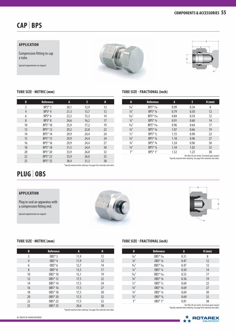
A
D
H
E
A
D
H
55
ALL RIGHTS OF CHANGE RESERVED
COMPONENTS & ACCESSORIES
CAP | BPS
TUBE SIZE - METRIC (mm)
D Reference A E H
3 BPS* 3 20,1 12,9 12
4 BPS* 4 21,3 13,7 12
6 BPS* 6 23,3 15,3 14
8 BPS* 8 24,6 16,2 17
10 BPS* 10 25,9 17,2 19
12 BPS* 12 29,2 22,8 22
14 BPS* 14 29,9 24,4 24
15 BPS* 15 29,9 24,4 24
16 BPS* 16 29,9 24,4 27
18 BPS* 18 31,5 24,4 30
20 BPS* 20 33,9 26,0 32
22 BPS* 22 33,9 26,0 32
25 BPS* 25 38,4 31,3 38
TUBE SIZE - FRACTIONAL (inch)
D Reference A E H (mm)
1⁄16” BPS* 1⁄16 0.99 0.34 8
1⁄8” BPS* 1⁄8 0.79 0.50 12
3⁄16” BPS* 3⁄16 0.84 0.54 12
¼” BPS* ¼ 0.91 0.60 14
5⁄16” BPS* 5⁄16 0.96 0.64 17
3⁄8” BPS* 3⁄8 1.07 0.66 19
½” BPS* ½ 1.15 0.90 22
5⁄8” BPS* 5⁄8 1.18 0.96 27
¾” BPS* ¾ 1.24 0.96 30
7⁄8” BPS* 7⁄8 1.34 1.02 32
1” BPS* 1” 1.52 1.23 38
APPLICATION
Compression fitting to cap a tube.
Special requirements on request
PLUG | OBS
TUBE SIZE - METRIC (mm)
D Reference A H
3 OBS* 3 11,9 12
4 OBS* 4 11,9 12
6 OBS* 6 12,7 14
8 OBS* 8 13,5 17
10 OBS* 10 15,1 19
12 OBS* 12 17,5 22
14 OBS* 14 17,5 24
16 OBS* 16 17,5 27
18 OBS* 18 17,5 30
20 OBS* 20 17,5 32
22 OBS* 22 17,5 32
25 OBS* 25 20,6 38
TUBE SIZE - FRACTIONAL (inch)
D Reference A H (mm)
1⁄16” OBS* 1⁄16 0.31 8
1⁄8” OBS* 1⁄8 0.47 12
3⁄16” OBS* 3⁄16 0.47 12
¼” OBS* ¼ 0.50 14
5⁄16” OBS* 5⁄16 0.53 17
3⁄8” OBS* 3⁄8 0.56 19
½” OBS* ½ 0.69 22
5⁄8” OBS* 5⁄8 0.69 27
¾” OBS* ¾ 0.69 30
7⁄8” OBS* 7⁄8 0.69 32
1” OBS* 1” 0.81 38
APPLICATION
Plug to seal an apparatus with a compression fitting end.
Special requirements on request
Hex flats (H) are metric. Fractional upon request*Specify material when ordering. See page 8 for materials and codes.
Hex flats (H) are metric. Fractional upon request*Specify material when ordering. See page 8 for materials and codes.
*Specify material when ordering. See page 8 for materials and codes.
*Specify material when ordering. See page 8 for materials and codes.

D
D
56
ALL RIGHTS OF CHANGE RESERVED
COMPONENTS & ACCESSORIES
FRONT FERRULE | FF
TUBE SIZE - FRACTIONAL (inch)
D Reference
1⁄16” FF* 1⁄16
1⁄8” FF* 1⁄8
3⁄16” FF* 3⁄16
¼” FF* ¼
5⁄16” FF* 5⁄16
3⁄8” FF* 3⁄8
½” FF* ½
5⁄8” FF* 5⁄8
¾” FF* ¾
7⁄8” FF* 7⁄8
1” FF* 1”
TUBE SIZE - METRIC (mm)
D Reference
3 FF* 3
4 FF* 4
6 FF* 6
8 FF* 8
10 FF* 10
12 FF* 12
14 FF* 14
15 FF* 15
16 FF* 16
18 FF* 18
20 FF* 20
22 FF* 22
25 FF* 25
APPLICATION
Spare part for a double ferrule compression tube fitting.
Special requirements on request
BACK FERRULE | BF
TUBE SIZE - METRIC (mm)
D Reference
3 BF* 3
4 BF* 4
6 BF* 6
8 BF* 8
10 BF* 10
12 BF* 12
14 BF* 14
15 BF* 15
16 BF* 16
18 BF* 18
20 BF* 20
22 BF* 22
25 BF* 25
TUBE SIZE - FRACTIONAL (inch)
D Reference
1⁄16” BF* 1⁄16
1⁄8” BF* 1⁄8
3⁄16” BF* 3⁄16
¼” BF* ¼
5⁄16” BF* 5⁄16
3⁄8” BF* 3⁄8
½” BF* ½
5⁄8” BF* 5⁄8
¾” BF* ¾
7⁄8” BF* 7⁄8
1” BF* 1”
APPLICATION
Spare part for a double ferrule compression tube fitting.
Special requirements on request
FERRULE SET (10 of each) | SET
TUBE SIZE - METRIC (mm)
D Reference
3 SET* 3
4 SET* 4
6 SET* 6
8 SET* 8
10 SET* 10
12 SET* 12
14 SET* 14
15 SET* 15
16 SET* 16
18 SET* 18
20 SET* 20
22 SET* 22
25 SET* 25
TUBE SIZE - FRACTIONAL (inch)
D Reference
1⁄16” SET* 1⁄16
1⁄8” SET* 1⁄8
3⁄16” SET* 3⁄16
¼” SET* ¼
5⁄16” SET* 5⁄16
3⁄8” SET* 3⁄8
½” SET* ½
5⁄8” SET* 5⁄8
¾” SET* ¾
7⁄8” SET* 7⁄8
1” SET* 1”
APPLICATION
Set of 10 front and back ferrules.
Special requirements on request
*Specify material when ordering. See page 8 for materials and codes.
*Specify material when ordering. See page 8 for materials and codes.
*Specify material when ordering. See page 8 for materials and codes.
*Specify material when ordering. See page 8 for materials and codes.
*Specify material when ordering. See page 8 for materials and codes.
*Specify material when ordering. See page 8 for materials and codes.

A
D
H
D
A
H
H
F
57
ALL RIGHTS OF CHANGE RESERVED
COMPONENTS & ACCESSORIES
NUT | ES
TUBE SIZE - METRIC (mm)
D Reference A H
3 ES* 3 11,9 12
4 ES* 4 11,9 12
6 ES* 6 12,7 14
8 ES* 8 13,5 17
10 ES* 10 15,1 19
12 ES* 12 17,5 22
14 ES* 14 17,5 27
15 ES* 15 17,5 27
16 ES* 16 17,5 27
18 ES* 18 17,5 30
20 ES* 20 17,5 32
22 ES* 22 17,5 32
25 ES* 25 20,6 38
TUBE SIZE - FRACTIONAL (inch)
D Reference A H (mm)
1⁄16” ES* 1⁄16 0.31 8
1⁄8” ES* 1⁄8 0.47 12
3⁄16” ES* 3⁄16 0.47 12
¼” ES* ¼ 0.50 14
5⁄16” ES* 5⁄16 0.53 17
3⁄8” ES* 3⁄8 0.56 19
½” ES* ½ 0.69 22
5⁄8” ES* 5⁄8 0.69 27
¾” ES* ¾ 0.69 30
7⁄8” ES* 7⁄8 0.69 32
1” ES* 1” 0.81 38
TUBE SIZE - METRIC (mm)
D Reference A H
3 EMS* 3 11,9 12
4 EMS* 4 11,9 12
6 EMS* 6 12,7 14
8 EMS* 8 13,5 17
10 EMS* 10 15,1 19
12 EMS* 12 17,5 22
14 EMS* 14 17,5 27
16 EMS* 16 17,5 27
18 EMS* 18 17,5 30
20 EMS* 20 17,5 32
22 EMS* 22 17,5 32
TUBE SIZE - FRACTIONAL (inch)
D Reference A H (mm)
1⁄16” EMS* 1⁄16 0.31 8
1⁄8” EMS* 1⁄8 0.47 12
3⁄16” EMS* 3⁄16 0.47 12
¼” EMS* ¼ 0.50 14
5⁄16” EMS* 5⁄16 0.53 17
3⁄8” EMS* 3⁄8 0.56 19
½” EMS* ½ 0.69 22
5⁄8” EMS* 5⁄8 0.69 27
¾” EMS* ¾ 0.69 30
7⁄8” EMS* 7⁄8 0.69 32
1” EMS* 1” 0.81 38
APPLICATION
Spare part for a double ferrule compression tube fitting.
Special requirements on request
KNURLED NUT | EMS
APPLICATION
Alternative knurled nut for a double ferrule compression tube fitting. Design for easier finger tightening.
Special requirements on request
BULKHEAD LOCKNUT | ECS
TUBE SIZE
Metric Fractional Reference H F (UNF)
3 1⁄8” ECS* H14 5⁄16 14 5⁄16” - 20
4 3⁄16” ECS* H14 3⁄8 14 3⁄8” - 20
6 ¼” ECS* H17 7⁄16 17 7⁄16” - 20
8 5⁄16” ECS* H17 ½ 17 ½” - 20
- 3⁄8” ECS* H19 9⁄16 19 9⁄16” - 20
10 - ECS* H19 5⁄8 19 5⁄8” - 20
12 ½” ECS* H24 ¾ 24 ¾” - 20
14-15-16 5⁄8” ECS* H27 7⁄8 27 7⁄8” - 20
18 ¾” ECS* H30 1 30 1” - 20
20-22 7⁄8” ECS* H36 11⁄8 36 11⁄8” - 20
25 1” ECS* H38 15⁄16 38 15⁄16” - 20
APPLICATION
Spare part for a double ferrule compression bulkhead fitting.
Special requirements on request
Hex flats (H) are metric. Fractional upon request*Specify material when ordering.
See page 8 for materials and codes.
*Specify material when ordering. See page 8 for materials and codes.
*Specify material when ordering. See page 8 for materials and codes.
*Specify material when ordering. See page 8 for materials and codes.
*Specify material when ordering. See page 8 for materials and codes.

D
D dP
D D2
58
ALL RIGHTS OF CHANGE RESERVED
COMPONENTS & ACCESSORIES
GAUGE | CCS
TUBE SIZE - FRACTIONAL & METRIC
D (inch) D2 (mm) Reference
1⁄8” 3 1⁄8 CCS 3
3⁄16” 4 3⁄16 CCS 4
¼” 6 ¼ CCS 6
5⁄16” 8 5⁄16 CCS 8
3⁄8” - 3⁄8 CCS
- 10 CCS 10
½” 12 ½ CCS 12
- 14 CCS 14
5⁄8” 16 5⁄8 CCS 16
¾” 18 ¾ CCS 18
- 20 CCS 20
7⁄8” 22 7⁄8 CCS 22
1” 25 1” CCS 25
PRE-ASSEMBLY TOOL | PSS
APPLICATION
Tool to pre-tighten compression tube fittings before first-time installation. Ideal for access restricted installations.
Special requirements on request
TUBE SIZE - METRIC (mm)
D Reference
3 PSS 3
4 PSS 4
6 PSS 6
8 PSS 8
10 PSS 10
12 PSS 12
14 PSS 14
16 PSS 16
18 PSS 18
20 PSS 20
22 PSS 22
25 PSS 25
TUBE SIZE - FRACTIONAL (inch)
D Reference
1⁄8" PSS 1⁄8
3⁄16" PSS 3⁄16
¼" PSS ¼
5⁄16" PSS 5⁄16
3⁄8" PSS 3⁄8
½" PSS ½
5⁄8" PSS 5⁄8
7⁄8" PSS 7⁄8
1" PSS 1"
TUBE SIZE - FRACTIONAL (inch)
D Reference d P
1⁄8” INS* 1⁄8 2 2 13⁄16”
3⁄16” INS* 3⁄16 1⁄8 1⁄8” 3⁄32”
¼” INS* ¼ 1⁄8 1⁄8” 3⁄32”
¼” INS* ¼ 3⁄16 3⁄16” 1⁄8”
5⁄16” INS* 5⁄16 3⁄16 3⁄16” 1⁄8”
5⁄16” INS* 5⁄16 ¼ ¼” 3⁄16”
3⁄8” INS* 3⁄8 3⁄16 3⁄16” 1⁄8”
3⁄8” INS* 3⁄8 ¼ ¼” 3⁄16”
½” INS* ½ ¼ ¼” 3⁄16”
½” INS* ½ 3⁄8 3⁄8” 5⁄16”
5⁄8” INS* 5⁄8 3⁄8 3⁄8” 5⁄16”
5⁄8” INS* 5⁄8 ½ ½” 7⁄16”
¾” INS* ¾ ½ ½” 7⁄16”
¾” INS* ¾ 5⁄8 5⁄8” 9⁄16”
1” INS* 1” ¾ ¾” 11⁄16”
TUBE SIZE - METRIC (mm)
D Reference d P
4 INS* 4 2 2 0,8
6 INS* 6 4 4 2
8 INS* 8 6 6 4
10 INS* 10 8 8 6,4
12 INS* 12 8 8 7,5
12 INS* 12 10 10 10,3
14 INS* 14 12 12 11,1
16 INS* 16 13 13 11,9
16 INS* 16 14 14 14,3
18 INS* 18 16 16 15,8
Dimensions D and D2 correspond to the tube dimension not to the gauge dimension
*Specify material when ordering. See page 8 for materials and codes.
*Specify material when ordering. See page 8 for materials and codes.
INSERT FOR PLASTIC TUBE | INS
APPLICATION
Hose connector insert. Allows connection of a flexible hose and/or to increase the rigidity.
Special requirements on request
APPLICATION
Gauge to measure correct tightness of compression tube fittings (see page 7).
Special requirements on request

59
ALL RIGHTS OF CHANGE RESERVED
COMPONENTS & ACCESSORIES
ISO/BSP PARALLEL THREAD
ISO thread size
ReferenceD
(mm / inch)P
(mm / inch)G
(mm / inch)
1⁄8" GBS 1⁄8 15,88 / 0.63 10,35 / 0.41 2,00 / 0.08¼" GBS ¼ 20,57 / 0.81 13,74 / 0.54
2,03 / 0.083⁄8" GBS 3⁄8 23,80 / 0.94 17,28 / 0.68½" GBS ½ 28,58 / 1.13 21,54 / 0.85
2,50 / 0.10¾" GBS ¾ 34,93 / 1.38 27,05 / 1.061" GBS 1" 42,80 / 1.69 33,89 / 1.33
ISO thread size
ReferenceD
(mm / inch)P
(mm / inch)G
(mm / inch)
1⁄8" GBS/FPM 1⁄8 15,88 / 0.63 10,35 / 0.41 2,00 / 0.08¼" GBS/FPM ¼ 20,57 / 0.81 13,74 / 0.54
2,03 / 0.083⁄8" GBS/FPM 3⁄8 23,80 / 0.94 17,28 / 0.68½" GBS/FPM ½ 28,58 / 1.13 21,54 / 0.85
2,50 / 0.10¾" GBS/FPM ¾ 34,93 / 1.38 27,05 / 1.061" GBS/FPM 1" 42,80 / 1.69 33,89 / 1.33
ISO/BSP PARALLEL THREAD
ISO thread size
ReferenceD
(mm / inch)P
(mm / inch)G
(mm / inch)
1⁄8" GCU 1⁄8 14,98 / 0.59 9,91 / 0.39 1,0 / 0.04¼" GCU ¼ 18,03 / 0.71 13,97 / 0.55
1,5 / 0.063⁄8" GCU 3⁄8 23,11 / 0.91 17,02 / 0.67½" GCU ½ 26,92 / 1.06 21,34 / 0.84
2,0 / 0.08¾" GCU ¾ 33,02 / 1.30 26,67 / 1.051" GCU 1" 38,10 / 1.50 33,53 / 1.32
GASKETS (steel/elastomer) | GBS
APPLICATION
- Provides a seal with male ISO/BSPP K parallel thread. The standard gasket is composed of a nitrile NBR inner ring bonded to a carbon steel outer ring. To order a fluorocarbon gasket, add FPM.
- See page 9 for details.
Special requirements on request
GASKETS (copper) | GCU
APPLICATION
- Provides a seal with male ISO/BSPP G parallel threads.
- The gasket material is copper. - See page 9 for details.
Special requirements on request
GASKETS (PTFE) | GTE
ISO/BSP PARALLEL THREAD
ISO thread size
Reference D P G
Regular gaskets
¼" GTE ¼ 11,0 5,2 2,03⁄8" GTE 3⁄8 14,7 8,0 2,0½" GTE ½ 18,3 14,0 2,5¾" GTE ¾ 23,8 18,0 3,0
Thin gaskets
¼" GTE ¼ 11,0 5,2 1,5¼" GTE ¼ 11,0 5,2 1,0¼" GTE ¼ 11,0 5,2 0,5
APPLICATION
- Provides a seal on stainless steel pressure gauges equipped with ISO/BSPP G parallel female threads. The gasket material is PTFE.
- See page 9 for details.
Special requirements on request
GASKETS (PCTFE) | GKF
ISO/BSP PARALLEL THREAD
ISO thread size
ReferenceD
(mm / inch)P
(mm / inch)G
(mm / inch)
Regular gaskets
¼" GKF ¼ 11,0 / 0.43 5,2 / 0.20 2,0 / 0.083⁄8" GKF 3⁄8 14,7 / 0.58 8,0 / 0.31 4,0 / 0.16½" GKF ½ 18,3 / 0.72 14,0 / 0.5 2,5 / 0.10
Thin gaskets
¼" GKF ¼ 11,0 / 0.43 5,2 / 0.20 1,5 / 0.06¼" GKF ¼ 11,0 / 0.43 5,2 / 0.20 1,0 / 0.04¼" GKF ¼ 11,0 / 0.43 5,2 / 0.20 0,5 / 0.023⁄8" GKF 3⁄8 14,7 / 0.58 8,0 / 0.31 1,5 / 0.063⁄8" GKF 3⁄8 14,7 / 0.58 8,0 / 0.31 1,0 / 0.043⁄8" GKF 3⁄8 14,7 / 0.58 8,0 / 0.31 0,5 / 0.02
APPLICATION
- Provides a seal on stainless steel pressure gauges equipped with ISO/BSPP G parallel female threads.
- The gasket material is PCTFE. - See page 9 for details.
Special requirements on request

60
ALL RIGHTS OF CHANGE RESERVED
COMPONENTS & ACCESSORIES
DEBURRING TOOL
APPLICATION
To deburr copper tubing. Deburrs the inside and outside diameters of 4 mm to 25 mm, and 1⁄8" to 1" inch tubing.
Reference: 47490000.
Special requirements on request
TUBE CUTTER
APPLICATION
The Rotarex tube cutter cuts stainless steel, soft copper and aluminium tubing from 3 to 25 mm and 1⁄8 to 1 inch outside diameter.
Special requirements on request
PTFE TAPE
APPLICATION
Tape 12 mm x 0,1 mm x 12 m Density: 1g/cm3
Reference 13008006.
Special requirements on request
MANUAL TUBE BENDER
Reference Tube Thickness
474900312 min. ≤ 1 mm 0 3 to 10 mm
474900409 min. ≤ 1 mm 0 ¼ to 5⁄8 mm R 3 - 3,5 D
474900610 min. ≤ 1 mm 0 6 to 10 mm R 3 - 3,5 D
474900611 min. ≤ 1 mm 0 ¼"- 5⁄16"- R 3 D
474900612 min. ≤ 1 mm 0 10 mm R 3,5 D
474900613 min. ≤ 1 mm 0 12 mm R 3,5 D
474901214 min. ≤ 1 mm 0 12 to 14 mm R 3 to 3,5 D
474901654 min. ≤ 1 mm 0 5⁄8" R 54 mm
APPLICATION
Enables reliable and high precision bends in tubing made from materials that can be used with Rotarex tube fittings. Bending range from 3 to 14 mm, and ¼ to 5⁄8 inch, according to the selected model, Perfect handling by pre-molded wrists.
Special requirements on request

61
ALL RIGHTS OF CHANGE RESERVED
NOTES

62
ALL RIGHTS OF CHANGE RESERVED
To disassemble:
Before disassembling, mark the exact position of the nut as shown in the Disassembly image. You will need these markings to return to the exact assembly position when reassembling:
a - Mark the depth of the nut on the tube (at the back of the nut) b - Mark the alignment between the nut and the body (use the flats).
To reassemble:
1. Insert the tube with the crimped ferrules into the fitting. Make sure the tube end sits squarely against the fitting seat and that the front ferrule realigns with the tube crimp. Hand tighten as far as possible. Then, tighten the nut with a wrench until the nut returns to its exact original position. The marks are now aligned and you feel a significant resistance in the torque.
2. Now, give a slight additional torque on the wrench to ensure tightness
N.B: Inspection gauges are not relevant when reassembling fittings.
ASSEMBLY GUIDELINES
INITIAL ASSEMBLY
Rotarex Compression Tube Fittings are quick & easy to assemble:
Initial Assembly in 4 easy steps
1. Insert the tube in the ready-to-use fitting so that the tube end rests squarely against the shoulder (a).
2. Finger-tighten the nut on the body. The tube should not be able to turn freely. If the tube turns by hand or axially in the fitting, tighten the nut lightly with a wrench until the tube stops turning.
3. Mark the initial position of the nut with a marking pen. This is necessary to control the exact rotation to achieve the proper tightness.
4. Use a wrench to tighten the nut clockwise: - Fittings for tubes ¼” / 6 mm and higher: 1 ¼ turns - Fittings for tubes 3⁄16” / 4 mm and lower: ¾ turn
Confirm proper tightness with the inspection gauge (see page 7).
DISASSEMBLY & REASSEMBLY
a
b
1
2 3
4
1
2
a
Disassembly
Reassembly
Reassemble back to the exact original position
Then apply a slight additional torque
Insert tubing
Hand or wrench tighten until the tube stops turning
Wrench tighten 1 ¼ turns (¾ turns for tubes < 4 mm / 3⁄16")
Mark the exact position before disassembly
Mark the position with a marker
Ensure tubing butts squarely on the fitting shoulder
ASSEMBLY GUIDELINES

63
ALL RIGHTS OF CHANGE RESERVED
Port connector
1. To assemble the conical ferrule into a compression fitting, use a wrench to tighten the nut clockwise:
- for Port connector ¼”(6 mm) and higher : ¼ turn from the hand tightening position.
- for port connector 3⁄16”(4 mm) and lower: 1⁄8 turn from the hand tightening position.
Adaptor
2. To assembly the tube adaptor end into a Rotarex compression tube fitting, use a wrench to tighten the nut clockwise:
- Fittings for tube ¼”(6 mm) and higher : 1 ¼ turn - Fittings for tube 3⁄16”(4 mm) and lower: ¾ turn
ASSEMBLY GUIDELINES (continued)
PLUGS
For plugs, use a wrench to tighten the nut clockwise: - for plugs ¼” (6 mm) and higher : Use ¼ turn from the hand tightening position.
- for plugs 3⁄16” (4 mm) and lower: 1⁄8 turn from the hand tightening position.
O-RING MALE CONNECTORS
To assembly an O-ring fitting: - Lubricate the O-ring with a lubricant compatible to both the O-ring material and the system fluid
- Tighten by hand the male end into the female connector - Tighten slightly with a wrench until the male and female faces creates a metal-to-metal sealing
- Give a slight extra effort with the wrench.
PORT CONNECTOR AND TUBE ADAPTORS
1 2
When using port connectors, assemble the conical ferrule end first, then the tube adaptor end.
We advise you to keep the fitting still during assembly and desassembly.
WELD CONNECTORS
INSERT FOR PLASTIC TUBE
For weld connectors, proceed as follows: - Remove the nut and ferrules from the tube fitting end - Protect the tube fitting end with an OBS plug (or other type of protection)
- Tack weld the fitting on the pipe or tube - You can control the alignement before completing the welding. - Remove the OBS.
An INS insert helps to support plastic tubing within the fitting to prevent it from collapsing:
- Fully insert the INS into the soft tube
- Place the INS against the shoulder within the body - Tighten the nut and the ferrules following the standard assembling instructions.
N.B.: A simple hand tightening of the OBS is enough
Wrench tighten only ¼ turn (1⁄8 turn for plugs < 4mm / 3⁄16")
ASSEMBLY GUIDELINES

64
ALL RIGHTS OF CHANGE RESERVED
REFERENCE CHARTS
GAS COMPATIBILITY
Best Practice requires that you always verify the gas compatiblilty of any gas handling equipment before installation and operation. The chart below can help you verify the right material for your gas type.
Rotarex Fittings are standardly available in 2 material types, Brass and Stainless Steel 316L, each with its own advantage in different applications. For highly specialized applications, we offer 10 additional materials on request (see page 8). Please go to www.rotarex.com for gas compatibility of these optional materials.
KEY TO GAS COMPATIBILITY:
Locate your gas type in the below chart and see the gas compatibility of each standard material type. Only select materials that are compatible with your gas type.
GAS COMPATIBILITY WITH MATERIALS
GAS Brass SS 316L PA 6.6 PTFE PCTFE NBR FPM EPDM
Acetylene C2H
2OK OK OK OK
Ammonia NH3
OK OK OK OK OK
Argon Ar OK OK OK OK OK OK OK OK
Butane C4H
10OK OK OK OK OK OK OK
Carbon dioxide CO2
OK OK OK OK OK OK OK
Carbon monoxide CO OK OK OK OK OK OK OK
Ethane C2H
6OK OK OK OK OK OK OK
Ethylene C2H
4OK OK OK OK OK
Helium He OK OK OK OK OK OK OK
Hydrogen H2
OK OK OK OK OK OK OK
Hydrogen Sulfide H2S OK OK OK OK OK OK
Krypton Kr OK OK OK OK OK OK OK
Methane CH4
OK OK OK OK OK OK OK
Nitric Oxide NO OK Please consult - depends on proportion of NO in the mixture
Nitrogen N2
OK OK OK OK OK OK OK OK
Nitrous Oxide N2O OK Please consult - depends on proportion of N2O in the mixture
Oxygen O2
OK OK < 30 bar / 435 psi OK OK
Propane C3H
8OK OK OK OK OK OK
Silane SiH4
OK OK OK OK
Sulphur Dioxide SO2
OK OK OK OK
Sulphur Hexafluoride SF6
OK OK OK OK OK OK OK OK

65
ALL RIGHTS OF CHANGE RESERVED
REFERENCE CHARTS
FLOW CONVERSION
m3/h l/h foot3/min l/s cm3/s
m3/h 1 1 x 10³ 0.589 0,2778 277,78
l/h 1 x 10⁻³ 1 5.885 x 10⁻⁴ 2,778 x 10-4 0,2778
foot3/min 1,69 1,699 x 103 1 0,4719 471,95
l/s 3,6 3,6 x 10³ 2.119 1 103
cm3/s 3,6 x 10⁻³ 3,6 2.119 x 10⁻³ 10-3 1
PRESSURE CONVERSION
bar mbar kPa MPa atm psi
bar 1 103 100 0,1 0,987 14.5
mbar 10-3 1 0,1 10-4 9,869 x 10-4 14.5 x 10⁻³
kPa 10-2 10 1 10-3 9,869 x 10-3 0.145
MPa 10 104 103 1 9,869 145
atm 1,013 1013 101,3 1,013 x 10-1 1 14.69
psi 6,89 x 10⁻² 68,9 6,89 6,89 x 10⁻³ 6,8 x 10⁻² 1
CONVERSION CHARTS
DIMENSION
metric inches inch fractional inch decimal metric (mm)
3 0.135 1⁄16" 0.063 1,59
6 0.270 1⁄8" 0.125 3,18
8 0.360 3⁄16" 0.188 4,76
10 0.450 ¼" 0.250 6,35
12 0.540 5⁄16" 0.313 7,94
14 0.630 3⁄8" 0.375 9,53
16 0.720 ½" 0.500 12,70
18 0.810 7⁄16" 0.438 11,11
20 0.900 5⁄8" 0.625 15,88
22 0.990 ¾" 0.750 19,05
25 1.125 7⁄8" 0.875 22,23
1" 1.000 25,40
TEMPERATURE
C° F° K° R°
-20 -4 253 456
-10 14 263 474
0 32 273 492
10 50 283 510
20 68 293 528
30 86 303 546
40 104 313 564
50 122 323 582
60 140 333 600
70 158 343 618
80 176 353 636
90 194 363 654
100 212 373 672
200 392 473 852
300 572 573 1032
400 752 673 1212
500 932 773 1392
600 1112 873 1572
700 1292 973 1752
800 1472 1073 1932
900 1652 1173 2112
1000 1832 1273 2292

A WORLD OF GAS CONTROL SOLUTIONSROTAREX is helping engineers worldwide to get better gas results: from ultra high purity production and medical care facilities to industrial and LPG applications, as well as alternative energy vehicles, fi re suppression, diving, aerospace, cryogenics, laboratory, petro-chemical and welding. ROTAREX applies over 90 years of know-how and experience to custom design, develop and manufacture the high performance valves, regulators and fi ttings to suit your needs, all in one hand. Discover the diff erence ROTAREX can make in your world.
COMPLETE SOLUTIONS FROM SOURCE TO PROCESS.
MEDITECCYLINDER VALVES EQUIPMENT FIRETEC AUTOMOTIVE LPG/SRG

AUSTRALIA / BRASIL / CHINA / FRANCE / INDIA / ITALY / JAPAN / LUXEMBOURG / MIDDLE EAST / RUSSIA / S INGAPORE / SPAIN / THAILAND / USA
INDUSTRIALCYLINDER VALVES
UHPCYLINDER VALVES
MEDICAL VALVES& REGULATORS
FIRE SUPPRESSIONLPG VALVES
REGULATORS & GAUGES
SPECIALTY GAS VALVES REGULATORS & FITTINGS CRYOGENIC VALVES AUTOMOTIVE
WATERTEC

www.rotarex.com
© 2012 - ROTAREX S.A.
ROTAREX Equipment™ ROTAREX S.A.
PR-EN-0312
WORLDWIDE HEADQUARTERS
ROTAREX S.A.24, rue de Diekirch, BP 19
L-7505 Lintgen
Luxembourg
Tel.: +352 32 78 32-1
Fax: +352 32 78 32-854
E-mail: [email protected]
REGIONAL / COUNTRY HEAD QUARTERS
NORTH AMERICA
USARotarex North America
221 Westec Drive
Westmoreland Technology Park I
Mt. Pleasant, Pennsylvania 15666 USA
Tel.: +1 724-696-43 40
Fax: +1 724-696-43 64
E-mail: info@ rotarex-inc.rotarex.com
SOUTH AMERICA
BRASILRotarex Brazil Ltda
Cond. Ind. Portal da Anhanguera Estr. Municipal
Gov. Mário Covas, S/N
13279-411 Bairro Macuco -Valinhos
Sao Paulo Brazil
Tel.: +55 11 3518 0800
Fax: +55 19 3869-1503
E-mail: [email protected]
EUROPE
FRANCE, BENELUX, GERMANYRotarex Equipment Customer Service
24, rue de Diekirch, BP 19
L-7505 Lintgen, Luxembourg
Tel.: +352 32 78 32-1
E-mail: [email protected]
ITALYRotarex Italia S.r.l.
46 Via Giacomo Matteotti
I-25080, Ciliverghe di Mazzano (BS) Italy
Tel.: +39 030 212 05 50
Fax: +39 030 212 23 62
E-mail: [email protected]
SPAINRotarex Spain
7 - 8° G2 C/ Estébanez Calderón
E-28020 Madrid Spain
Tel.: +34 650 908 856
E-mail: [email protected]
RUSSIARotarex Rus
Tverskaya street, 20/1 bldg. 1 of 506
125009, Moscow Russia
Tel.: +7 985 125 7776
Skype: rotarexrus
E-mail: [email protected]
POLANDRotarex Polska
13 Gröbli
PL 49-300 Brzeg, Poland
Tel.: +48 77 416 40 16
Fax: +48 77 416 20 99
E-mail: [email protected]
ASIA
MIDDLE EASTRotarex Middle East
Jebel Ali Free Zone - Lob 14 #224
P.O. Box 261952 - JAFZA
Dubai, U.A.E.
Tel.: +971 (0) 4 88 76 701
Fax: +971 (0) 4 88 76 702
E-mail: [email protected]
CHINARotarex Star
60 Yuan Zhong Road
Shanghai Nanhui Industrial Zone
201300, Shanghai China
Tel.: +86-21 5800 4000
Fax: +86-21 5800 3226
E-mail: [email protected]
SINGAPORERotarex Fareast Pte Ltd
10 Ubi Crescent
Ubi Techpark, Lobby C, #06-55
408564 Singapore
Tel.: +65 64 72 37 27
Fax: +65 64 72 45 28
E-mail: [email protected]
JAPANRotarex Japan Ltd
2F, 5-1 Blog, 2-10-6 Shiba
Minato-Ku, Tokyo
105-0014 JAPAN
Tel.: +81 3 6809 6973
Fax: +81 3 6809 6975
E-mail: [email protected]
INDIARotarex ENGG. PVT. LTD.
1003, Vishwa Deep, Building
Plot No. 11, Distt. Centre,
110058 Janakpuri, - India
Tel.: +91-11 415 790 28
E-mail: [email protected]
THAILANDRotarex (Thailand) Co Ltd.
297, Wanglee Tower
3rd floor, Unit C, Surawong Road
Suriyawong, Bangrak,
Bangkok 10500 Thailand
Tel.: +66 2635 71 79
E-mail: [email protected]
SOUTH KOREARotarex Luz Tech Co.
305-500, 547 Yongsan-dong
Yuseong-gu
Taejon, Korea
Tel.: +82 42 825 8911
Fax: +82 42 825 8913
E-mail: [email protected]
OCEANIA
AUSTRALIARotarex Australia/New Zealand
Hornsby Heights,
Sydney, NSW, 2077
Tel.: +61 477 477 481
E-mail: [email protected]