Embed Size (px)
Citation preview

Compressed GasesSafety Handbook

PGStraining.com
INDEX
Cylinder Identification ChartCylinder ValvesGas PropertiesRegulatorsHosesFlashback Arrestors / Flashbacks Mobile Oxy-Fuel SystemsSingle Cylinder SupplyManifold SystemsCylinder HandlingGas Stores Transporting Cylinders by Road
3-45
6-1516-2021-2223-2627-3132-3334-3839-4041-4647-53
2

PGStraining.com
21
OLD
NEW
2 3 4 5 6
ToxicFlammableOxidisingInert/UnreactiveToxic & FlammableToxic & Oxidant
123456
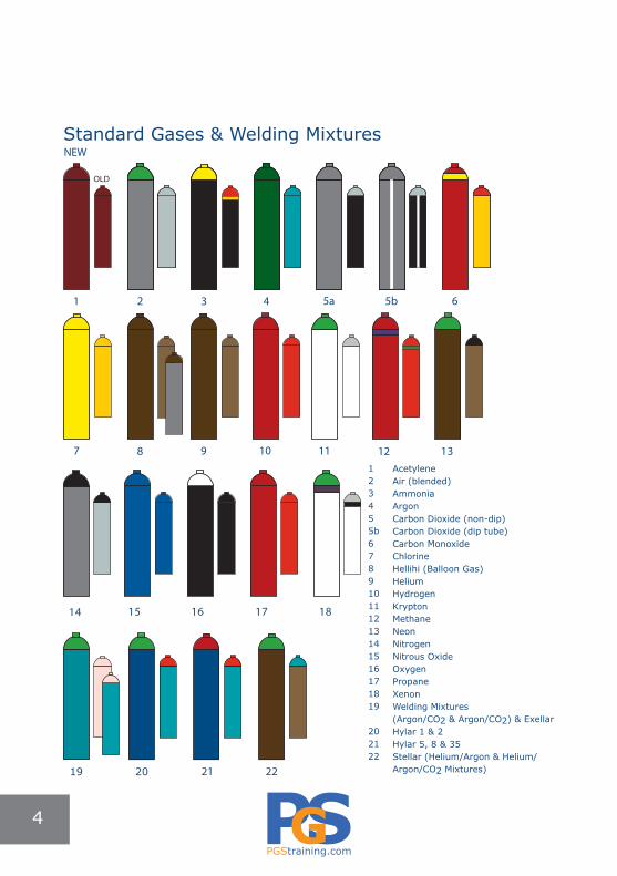
An ongoing programme is underway to ensure cylinder colours comply with EN1089-3. Repainting is taking place at the time of scheduled cylinder testing. Until this programme is completed, cylinders bearing both the old & new colour schemes will be circulation.
IMPORTANTRead all cylinder labels & stencilled marks. Do not rely on colour of cylinder alone.Never lift or crane a cylinder using its guard.
Colour chart shown is with permission from ‘Air Liquide’
Generic & Special Gas Mixtures
CYLINDER IDENTIFICATION CHART
3
PGStraining.com
AcetyleneAir (blended)AmmoniaArgonCarbon Dioxide (non-dip)Carbon Dioxide (dip tube)Carbon MonoxideChlorineHellihi (Balloon Gas)HeliumHydrogen KryptonMethaneNeonNitrogen Nitrous OxideOxygenPropaneXenonWelding Mixtures(Argon/CO2 & Argon/CO2) & ExellarHylar 1 & 2Hylar 5, 8 & 35Stellar (Helium/Argon & Helium/Argon/CO2 Mixtures)
7 8 9 10 11
Standard Gases & Welding Mixtures
123455b678910111213141516171819
202122
21 22
1
NEW
OLD
2 3 4 5a 5b 6
12 13
14 15 16 17 18
19 20
44
PGStraining.com
• Different gas types have differing connections to reduce the possibility of cross connection.
• Valve outlets are not unique to all gases.Note: Oxygen has the same outlet thread connection as inert gases like Nitrogen or Argon.
• Gas users must check cylinder label for compatibility to equipment being connected.
• Equipment for oxygen service must be specified for oxygen service & not used for other gases.
• Equipment must match the valve outlet connection to ensure a safe, leak free union.
• Flammable gases have left-hand threads. • Non-flammable gases have right-hand threads.
Single Cylinder Valve Standard FittedBelow 250 bar BS 341
250- 300 barBS ISO 5145 (Identical to New European Valve Outlet Connection –NEVOC connections)
Air Liquide Bank/Bundles Valve Standard Fitted
Below 250 bar Identical pair of BS341 outlet defined by gas type
300 bar
Two Valve Outlets:1. 300 bar Mandatory NEVOC Connection
delivering full pressure2. BS341 pressure reduced delivering circa
160 bar
CYLINDER VALVES
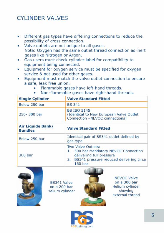
BS341 Valve on a 200 bar
Helium cylinder
NEVOC Valveon a 300 bar
Helium cylinder showing
external thread
5

PGStraining.com
GAS PROPERTIES ALWAYS REFER TO SAFETY DATA SHEETS
Hydrogen 0.06
Nitrogen0.9
Acetylene0.9
Argon1.4
CarbonDioxide
1.5
Propane1.5
Helium0.1
Oxygen1.1
FLAMMABLE ACETYLENEC2H2
PROPANEC3H8
BUTANEC4H10
HYDROGEN
OXIDISING OXYGENO2
NITROUS OXIDE FLUORINE CHLORINE
INERT NITROGENN2
ARGONAr
CARBON DIOXIDE HELIUM
CORROSIVE CHLORINE AMMONIA
TOXIC CARBON MONOXIDE
SULPHUR DIOXIDE AMMONIA
PYROPHORIC SILANE
SPECIFIC GRAVITIES @ 15°C IN RELATION TO AIR
6

PGStraining.com
GAS PROPERTIES ALWAYS REFER TO SAFETY DATA SHEETS
OXYGEN
Oxidising Gas
Colourless, odourless, tasteless, supports life.
Forms 21% of the atmosphere.
Additional 3% Oxygen in an atmosphere may prevent fires being put out with water.
Reacts violently with hydrocarbons such as oils, greases, paints & solvents.
May be leak checked with an appropriate Leak Detecting Fluid - should not be leak checked with soap solutions.
PTFE tapes should not be used on Oxygen regulators & fittings. (A specialised PTFE may be seen being used in some applications where applied by competent qualified engineers only.)
Strongly supports combustion & may be a particular hazard if released into confined spaces.
Slightly heavier than air with a Specific Gravity of 1.1 where air = 1.
Fittings are right hand thread.
Hose on welding sets is normally coloured blue.
Cylinder has no safety relief device fitted.
Gas obtained from the air through liquefaction.
The absence of Oxygen leads to asphyxiation: a. 18% or less is considered dangerous b. 10% leads to unconsciousness c. Below 10% usually fatalRefer to page 55 for further effects of Oxygen deficiency
7
PGStraining.com
GAS PROPERTIES ALWAYS REFER TO SAFETY DATA SHEETS
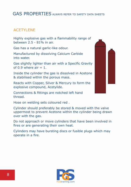
ACETYLENE
Highly explosive gas with a flammability range of between 2.5 - 81% in air.
Gas has a natural garlic-like odour.
Manufactured by dissolving Calcium Carbide into water.
Gas slightly lighter than air with a Specific Gravity of 0.9 where air = 1.
Inside the cylinder the gas is dissolved in Acetone & stabilised within the porous mass.
Reacts with Copper, Silver & Mercury to form the explosive compound, Acetylide.
Connections & fittings are notched left hand thread.
Hose on welding sets coloured red .
Cylinder should preferably be stored & moved with the valve uppermost to prevent Acetone within the cylinder being drawn over with the gas.
Do not approach or move cylinders that have been involved in fires or are generating their own heat.
Cylinders may have bursting discs or fusible plugs which may operate in a fire.
8

PGStraining.com
GAS PROPERTIES ALWAYS REFER TO SAFETY DATA SHEETS
ARGON
Inert Gas.
Colourless, odourless & tasteless.
Forms less than 1% of the atmosphere.
A simple asphyxiant as it can displace Oxygen.
The absence of Oxygen leads to asphyxiation: a. 18% or less is considered dangerous b. 10% leads to unconsciousness c. Below 10% usually fatal
Heavier than air with a Specific Gravity of 1.4 where air = 1.
Fittings right hand thread.
Hose coloured black.
Obtained through the liquefaction of air.
Cylinder has no pressure relief devices fitted.
May be leak checked with an approved leak detecting fluid.
9
PGStraining.com
GAS PROPERTIES ALWAYS REFER TO SAFETY DATA SHEETS
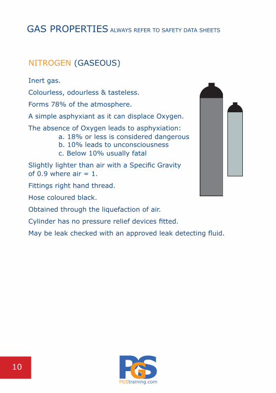
NITROGEN (GASEOUS)
Inert gas.
Colourless, odourless & tasteless.
Forms 78% of the atmosphere.
A simple asphyxiant as it can displace Oxygen.
The absence of Oxygen leads to asphyxiation: a. 18% or less is considered dangerous b. 10% leads to unconsciousness c. Below 10% usually fatal
Slightly lighter than air with a Specific Gravity of 0.9 where air = 1.
Fittings right hand thread.
Hose coloured black.
Obtained through the liquefaction of air.
Cylinder has no pressure relief devices fitted.
May be leak checked with an approved leak detecting fluid.
10
PGStraining.com
GAS PROPERTIES ALWAYS REFER TO SAFETY DATA SHEETS
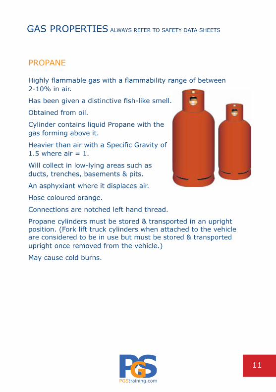
PROPANE
Highly flammable gas with a flammability range of between 2-10% in air.
Has been given a distinctive fish-like smell.
Obtained from oil.
Cylinder contains liquid Propane with the gas forming above it.
Heavier than air with a Specific Gravity of 1.5 where air = 1.
Will collect in low-lying areas such as ducts, trenches, basements & pits.
An asphyxiant where it displaces air.
Hose coloured orange.
Connections are notched left hand thread.
Propane cylinders must be stored & transported in an upright position. (Fork lift truck cylinders when attached to the vehicle are considered to be in use but must be stored & transported upright once removed from the vehicle.)
May cause cold burns.
11

PGStraining.com
GAS PROPERTIES ALWAYS REFER TO SAFETY DATA SHEETS
HYDROGEN Highly flammable.
Colourless, odourless & tasteless gas.
Lighter than air with a Specific Gravity of 0.06 where air = 1.
Non-toxic but may act as an asphyxiant in high concentrations.
Flammability range in air 4-75% by volume.
Hydrogen diffuses rapidly & may leak from systems which may be gas tight for other gases.
Never ‘snift’ Hydrogen cylinders, Hydrogen has a very low energy of ignition & may ignite if released suddenly from the cylinder.
Gas flame is invisible in normal light.
Consider non spark tools.
Protect from sources of heat & ignition.
Consider earthing lines & equipment where there is the possibility of electrostatic discharge.
Use appropriate leak detection methods.
Specialist Hydrogen monitors may warn of the build up of gas in the workspace.
12

PGStraining.com
GAS PROPERTIES ALWAYS REFER TO SAFETY DATA SHEETS
AMMONIA Flammable liquefied gas.
Toxic by inhalation; colourless.
Lighter than air with a Specific Gravity of 0.6 where air = 1.
Flammability range 15-30% by volume in air.
Corrosive effects to eyes, respiratory system & skin.
In a fire may produce the following toxic &/or corrosive fumes by thermal decomposition: Nitric Oxide; Nitrogen Dioxide.
May react violently with oxidants.
May react violently with acids.
Reacts with water to form corrosive alkalis.
Wear suitable protective clothing, gloves, eye & face protection.
Extinguishing a leaking gas flame may lead to spontaneous or explosive re-ignition.
Containers should normally be kept below 50°C in a wellventilated area.
Purge air from system before introducing gas.
UK Long-Term Exposure Limit 25 ppm.
UK Short -Term Exposure Limit 35 ppm.
13

PGStraining.com
GAS PROPERTIES ALWAYS REFER TO SAFETY DATA SHEETS
HELIUM Inert gas.
A colourless odourless gas.
Lighter than air with a Specific Gravity of 0.14 where air = 1.
An asphyxiant in high concentrations.
Helium diffuses rapidly & may leak from systems that are gas tight for other gases.
14

PGStraining.com
GAS PROPERTIES ALWAYS REFER TO SAFETY DATA SHEETS
CARBON DIOXIDE
Non-toxic liquefied gas under pressure.
Odour in the form of a sharp smell may become apparent at high concentrations.
Asphyxiant in high concentrations.
Heavier than air with a Specific Gravity of 1.5 where air=1.
Slightly corrosive in the presence of moisture.
If Carbon Dioxide is dissolved in water, particularly at elevated pressures & in the presence of Oxygen, materials resistant to Carbonic Acid need to be considered.
Use only properly specified equipment for this product.
One volume of liquid will give approximately 500 volumes of gas.
Contact with liquid may cause cold burns &/or frostbite.
Low concentrations of Carbon Dioxide cause increased respiration & headache.Refer to page 56 for effects of Carbon Dioxide enrichment.
Short-Term Exposure Limit 15,000 volume parts per million.
Long-Term Exposure Limit 5,000 volume parts per million.
Sublimates from solid form (Dry Ice) at -78°C.
Use in well ventilated areas.
Carbon Dioxide monitoring is recommended if it is used or stored in confined spaces.
Cylinder vapour pressure above liquid product is 57.3 bar at 20°C.
15

PGStraining.com
CylinderCorrectly labelled &/or certificated by Supplier.Cylinder colour appropriate to the label. (Reject if information incorrect)Contents appropriate for application.Cylinder pressure not more than regulator pressure rating.Secured against movement.
Cylinder ValveCapped if new.Undamaged.Free from oils, greases & PTFE tape.Free from moisture, dirt & debris.
Regulator Body & Pressure Adjustment ScrewLabel in place. Undamaged.Max inlet pressure appropriate for the cylinder in use.Max outlet pressure appropriate for application.Manufacturers name / logo in place.Pressure Adjustment Screw stays fixed to the body of the regulator.Note: there are exceptions to this rule - some Nitrogen & Hydrogen regulators for example have a ‘T’ bar system which may be removable.Pressure Adjustment Screw operates freely & to full extent.European or British Standard BS EN 2503.Check the regulator is not due its ‘Periodic recorded examination’.
REGULATORS BEFORE USE CHECKS
2
4
6
8 bar 10 12 14 16
psi
50
100
150
200
50
100
psi1000
2000
5000
ISO
250
3
GAS TyPE
MAX. INLET:300 bar
MAX. OUTLET:0.10
DECREASE
INCR
EASE
CD WINSPECT/REPLAC E201 9
hP
hP LP
LP
Bull nose
EN ISO
Standard Pressure adjustment screw
Maximum inlet &outlet pressure
Recommendedreplacement datestamp
16

PGStraining.com
Regulator BullnoseBullnose free from damage.Note: In some instances a rubber ‘o’ seal may be present -this should only be replaced with an approved part.Threads undamaged.Free from oil greases, solvents & PTFE tape90° to the body.Tightening nut undamaged & of correct thread type.Free from unauthorised modifications or repairs.Regulator Outlet ConnectionThreads undamaged.Free from oil, greases, solvents, PTFE tape & carbon deposits.Free from unauthorised modifications or repairs.Regulator Pressure Relief ValvesExternal-no damage, free from unauthorised modifications or repairs.Internal-outlet opening free from obstruction.Regulator GaugesIn place & correct for the gas type.Marked EN562 &/or ISO5171.Clear covers in place & undamaged.Needles reading zero, correct side of stop, not bent.Appropriate high & low pressure scales.Backs in place.Free from unauthorised modifications or repairs.Five Year RuleManufacturer date stamp present or regulator known to be less than 5 years old. Note: It is recommended that regulators should not be used where they are more than 5 years old. (or whatever service life the manufacturer recommends)
Connect to CylinderOnly if in good condition & passing the above checks
REGULATORS BEFORE USE CHECKS
17

PGStraining.com
Rising Pressure CharacteristicTo open the regulator valve, force is applied via the spring.
The force of the spring must be sufficient to overcome the gas cylinder pressure which is acting to close the internal valve pin.
During use the cylinder pressure decreases therefore the force acting to close the valve also decreases.
The result is that the pressure adjustment screw spring forces the valve open further.
Consequently the pressure rises on the low-pressure side of the regulator & the low pressure gauge indicates an increase in outlet pressure.
An outlet pressure rise of 50% is typically experienced during operation & must be countered by winding out the pressure adjustment screw slightly at intervals over prolonged use.
The above chart shows the rising pressure characteristic of a single stage regulator.
In this example the regulator has been set to 30 psi.
REGULATORS SINGLE STAGE REGULATORS
Cylinder pressure
Reg
ulat
or o
utle
t pr
essu
re
Time
Time20
25
30
35
40
Rising outlet pressure using single stage
regulator
3000 2400 1800 1200
18
PGStraining.com
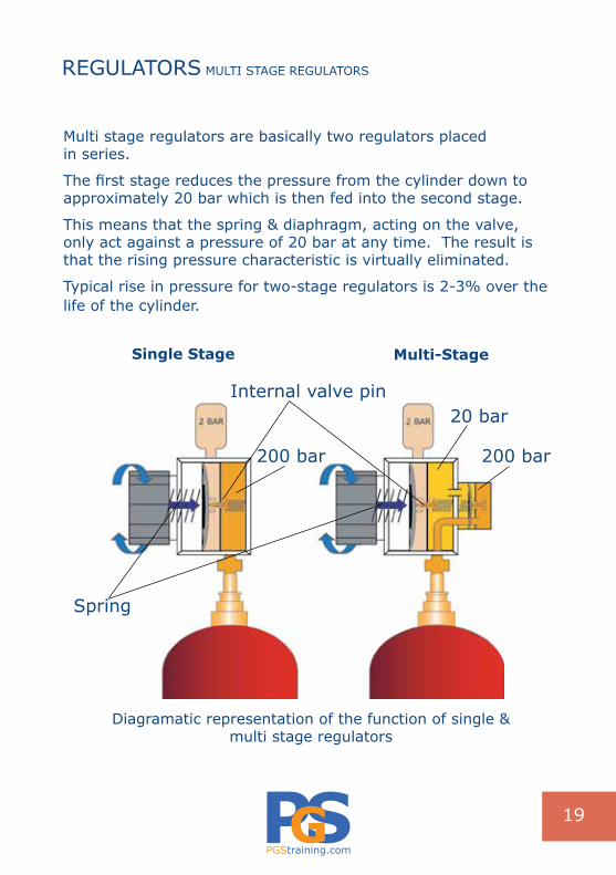
Multi stage regulators are basically two regulators placed in series.
The first stage reduces the pressure from the cylinder down to approximately 20 bar which is then fed into the second stage.
This means that the spring & diaphragm, acting on the valve, only act against a pressure of 20 bar at any time. The result is that the rising pressure characteristic is virtually eliminated.
Typical rise in pressure for two-stage regulators is 2-3% over the life of the cylinder.
REGULATORS MULTI STAGE REGULATORS
Single Stage Multi-Stage
Spring
Internal valve pin
200 bar
20 bar
Diagramatic representation of the function of single & multi stage regulators
200 bar
19
PGStraining.com
CreepIt is important that cylinder valves are opened slowly to prevent damage to the nonmetallic parts within a regulator.
Such damage can lead to creep which appears as a slow increase of pressure on the outlet side of the regulator. The majority of internal damage to valve seats manifests itself as creep.
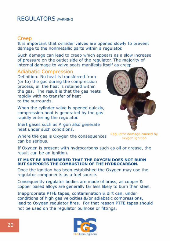
Adiabatic Compression Definition: No heat is transferred from (or to) the gas during the compression process, all the heat is retained within the gas. The result is that the gas heats rapidly with no transfer of heat to the surrounds.
When the cylinder valve is opened quickly, compression heat is generated by the gas rapidly entering the regulator.
Inert gases such as Argon also generate heat under such conditions.
Where the gas is Oxygen the consequences can be serious.
If Oxygen is present with hydrocarbons such as oil or grease, the result can be an ignition.
IT MuST BE REMEMBEREd ThAT ThE OxyGEN dOES NOT BuRN BuT SuPPORTS ThE COMBuSTION OF ThE hydROCARBON.Once the ignition has been established the Oxygen may use the regulator components as a fuel source.
Consequently regulator bodies are made of brass, as copper & copper based alloys are generally far less likely to burn than steel.
Inappropriate PTFE tapes, contamination & dirt can, under conditions of high gas velocities &/or adiabatic compressions, lead to Oxygen regulator fires. For that reason PTFE tapes should not be used on the regulator bullnose or fittings.
REGULATORS WARNING
Regulator damage caused byoxygen ignition
20
PGStraining.com
HOSE BEFORE USE CHECKS
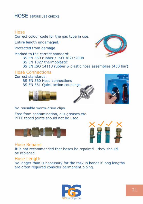
HoseCorrect colour code for the gas type in use.
Entire length undamaged.
Protected from damage.
Marked to the correct standard:BS EN 559 rubber / ISO 3821:2008BS EN 1327 thermoplasticBS EN ISO 14113 rubber & plastic hose assemblies (450 bar)
Hose ConnectionsCorrect standards:
BS EN 560 Hose connectionsBS EN 561 Quick action couplings
No reusable worm-drive clips.
Free from contamination, oils greases etc.PTFE taped joints should not be used.
Hose RepairsIt is not recommended that hoses be repaired - they should be replaced.
Hose LengthNo longer than is necessary for the task in hand; if long lengths are often required consider permanent piping.
21

PGStraining.com
Hose Fittings
Quarter Inch Non Return Valve(Hose Check Valve) Left Hand Thread
Hose Nipple or Tail
Nut Coupling Right Hand Thread
Five Eighths Non Return ValveRight Hand Thread
Equal CouplerLeft Hand Thread
Unequal CouplerRight Hand Thread
Hose Splicer
‘O’ Clips
HOSE HOSE FITTINGS & LENGTH
22

PGStraining.com
Flashback Arrestors These should be used where Oxygen & Fuel gas are in use supplying the same equipment. (See Page 23)Replace every 5 years or according to manufacturer’s recommendations.
5 Year LifeCheck the manufacturer’s date stamp or coding.
Not all manufacturers may date the flashback arrestors.
If code not present ascertain from purchase records or management whether the arrestor is under 5 years old.
If in doubt replace.
Flashback Arrestor Date Coding Positioning Examples:
Before Using a Flashback Arrestor Check:Appropriate for the gas in use.
The body is free from damage, contamination & correctly labelled.
Conforms to BS EN 730.
Connections are free from oil, grease, PTFE tape & other contamination.
Appropriate Maximum Working Pressure of the FBA.
Reset button or lever:Check for gas flow in the operating position; if no gas flow, check for signs of damage caused by previous flashback on the flashback arrestor or any attached hoses & regulators.
FLASHBACK ARRESTORS
23
PGStraining.com
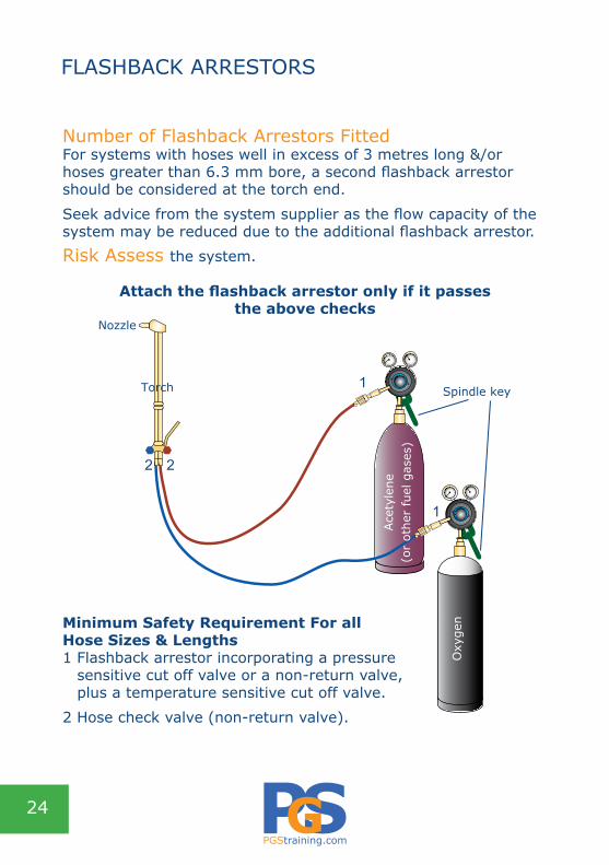
Number of Flashback Arrestors FittedFor systems with hoses well in excess of 3 metres long &/or hoses greater than 6.3 mm bore, a second flashback arrestor should be considered at the torch end.
Seek advice from the system supplier as the flow capacity of the system may be reduced due to the additional flashback arrestor.
Risk Assess the system.
Attach the flashback arrestor only if it passes the above checks
Minimum Safety Requirement For all Hose Sizes & Lengths1 Flashback arrestor incorporating a pressure
sensitive cut off valve or a non-return valve, plus a temperature sensitive cut off valve.
2 Hose check valve (non-return valve).
FLASHBACK ARRESTORS
1
1
2 2
Torch Ace
tyle
ne(o
r ot
her
fuel
gas
es)
Oxy
gen
Nozzle
Spindle key
24
PGStraining.com
FlashbackA potentially serious occurrence where a detonation takes place within the system & a high velocity pressure wave is generated.
This ‘explosion’ may cause damage to the system.
It is vital that the necessary safety equipment such as a Flashback Arrestor is used.
A flashback explosion propagating back into an Acetylene cylinder can lead to very serious incidents.
Flashback arrestors should be considered for all systems where a Fuel gas & Oxygen are used together in process equipment. (See Page 23)
CausesFailure to purge equipment / Faulty or damaged equipment. Operator error; i.e. incorrect light up procedure.Incorrect equipment selection.Gas velocity is less than flame burning velocity.Wrong size, blocked or dirty nozzle in use.Incorrect pressures set.No hose check valves (non return valves) in system.Kinked or trapped hoses.Failure to undertake routine maintenance.
It is vital to purge equipment before use. This is done to remove air or combustible gas mixtures from the process hoses thus preventing ignition.
Fuel gas is allowed to flow through the system for a few seconds thus pushing out unwanted air or gas mixtures.
Ensure the unwanted gas is vented safely to the atmosphere.Avoid carrying out this operation in confined spaces.
90% of all flashback incidents are caused by failure to carry out a purging procedure.
FLASHBACKS
25

PGStraining.com
With a gloved hand immediately close the cylinder valve.
If using Acetylene check the cylinder for signs of heat. Start at the top using the back of the hand & move down the cylinder.
If the cylinder appears to generate heat at any time immediately evacuate the area & call the Fire Brigade.
Under no circumstances attempt to move an Acetylenecylinder which is generating its own heat!
If the cylinder remains cool thoroughly check all equipment for damage.
Hoses showing signs of damage caused by the flashback must not be repaired.
It is not acceptable to cut out a damaged section & rejoin the hose.
Replace damaged hoses.
Consider checking the Acetylene cylinder for heat generation at intervals for a time after the initial flashback.
When welding & cutting remember the correct eye, face & safety clothing such as gloves, aprons, overalls etc should always be worn.For laboratory or other process equipment always check with the equipment manufacturer the initial set up & emergency actions required in the event of a flashback.They can also advise on the type & number of flashback arrestors to be used on their systems.
FLASHBACKS OPERATOR EMERGENCY ACTIONS
26

PGStraining.com
CylindersUpright & secured in an appropriate trolley or against a wall.Correctly labelled & colour coded to identify the gases & fill pressures. Valve outlets undamaged, clean & uncontaminated by oil, grease, solvents or PTFE tape.
Regulator Body (see pages 15-16)Labelled, Manufacturer’s name displayed.Undamaged, standard marked BS EN 2503.Pressure Adjustment Screw fixed to body & operates freely.Inlet & outlet pressure appropriate.
Bullnose (Not applicable if regulator already fitted)Undamaged uncontaminated & unmodified 90° to body.
Outlet Connection (Not applicable if regulator already fitted)Undamaged uncontaminated & unmodified.
Pressure Relief ValveIf fitted, undamaged & unmodified.
GaugesIn place & correct type.Undamaged uncontaminated & unmodified; backs in placeNeedles zero, correct side of stop & not bent.
Non Return / Hose Check Valves / Flame TrapsNon return valve in good condition; one per hose fitted at the torch end.
ConnectionsUndamaged, correct type of crimp fitting & fit for purpose.No worm wheel drive clips.
PTFE TapeCheck components & fittings are free from PTFE tape, joining compounds & sealants. PTFE tape shall not be used.
MOBILE OXY-FUEL SYSTEMS BEFORE USE CHECKS
27
PGStraining.com
Flashback Arrestors (see pages 22-23) Body undamaged, standard marked EN 730.Connections clean, uncontaminated.Pressure rating legible & suitable for cylinder. Date Stamp or Code less than 5 years or within manufacturer’s recommended life.Reset Button/Lever/Cap if fitted, not tied down, restricted, modified or damaged. Easily accessible.
Hoses (see pages 20-21)Correct colour code & Standard marked EN 559 / ISO 3821:2008Undamaged. Appropriate hose clips; no tapes or wires.Uncoiled & unwrapped from cylinders when in use.
Hose FittingsAppropriate thread; clean & uncontaminated.
Hose RepairsIf hoses have been repaired check they have been repaired competently using BS EN 560 fittings & the whole assembly fitted to BS EN 1256. Hose repairs however are not recommended.
TorchDesigned & rated for the gas & application to BS EN 5172. Undamaged & fit for purpose.
Rotary ValvesOperate freely; undamaged.
Lever Valve No excessive play.
Inlet Filters & ConnectionsClean & uncontaminated.
MOBILE OXY-FUEL SYSTEMS BEFORE USE CHECKS
28
PGStraining.com
Body Undamaged; uncontaminated; no discolouration.
PipeworkStraight & undamaged.
Nozzle Correct type; undamaged; uncontaminated.Designed & rated for the gas & torch type.Correct for the job in hand.Pressure correct for nozzle size & task - refer to Nozzle Data Sheets available from the manufacturer.
Nozzle SeatUndamaged; uncontaminated; threads in good condition.Round in shape (not oval).
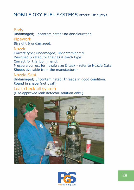
Leak check all system (Use approved leak detector solution only.)
MOBILE OXY-FUEL SYSTEMS BEFORE USE CHECKS
29
PGStraining.com
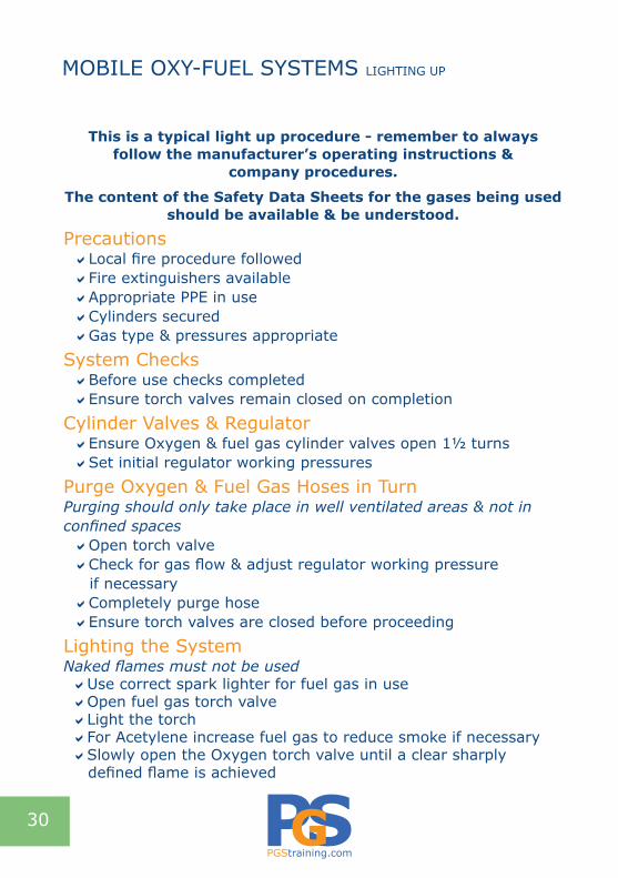
This is a typical light up procedure - remember to always follow the manufacturer’s operating instructions &
company procedures.
The content of the Safety Data Sheets for the gases being used should be available & be understood.
PrecautionsaLocal fire procedure followed aFire extinguishers availableaAppropriate PPE in use aCylinders securedaGas type & pressures appropriate
System ChecksaBefore use checks completed aEnsure torch valves remain closed on completion
Cylinder Valves & RegulatoraEnsure Oxygen & fuel gas cylinder valves open 1½ turns aSet initial regulator working pressures
Purge Oxygen & Fuel Gas Hoses in Turn Purging should only take place in well ventilated areas & not in confined spacesaOpen torch valveaCheck for gas flow & adjust regulator working pressure
if necessaryaCompletely purge hoseaEnsure torch valves are closed before proceeding
Lighting the System Naked flames must not be usedaUse correct spark lighter for fuel gas in useaOpen fuel gas torch valveaLight the torch aFor Acetylene increase fuel gas to reduce smoke if necessary aSlowly open the Oxygen torch valve until a clear sharply defined flame is achieved
MOBILE OXY-FUEL SYSTEMS LIGHTING UP
30
PGStraining.com
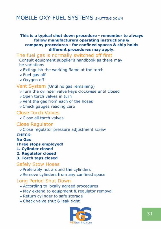
This is a typical shut down procedure - remember to always follow manufacturers operating instructions &
company procedures - for confined spaces & ship holds different procedures may apply.
The fuel gas is normally switched off first Consult equipment supplier’s handbook as there may be variationsaExtinguish the working flame at the torch aFuel gas offaOxygen off
Vent System (Until no gas remaining)aTurn the cylinder valve keys clockwise until closed aOpen torch valves in turnaVent the gas from each of the hosesaCheck gauges reading zero
Close Torch ValvesaClose all torch valves
Close RegulatoraClose regulator pressure adjustment screw
ChECK:No Gas Three stops employed!1. Cylinder closed2. Regulator closed3. Torch taps closed
Safely Stow Hoses aPreferably not around the cylindersaRemove cylinders from any confined space
Long Period Shut Down aAccording to locally agreed proceduresaMay extend to equipment & regulator removal aReturn cylinder to safe storageaCheck valve shut & leak tight
MOBILE OXY-FUEL SYSTEMS SHUTTING DOWN
31

PGStraining.com
Before Use ChecksCylinders Upright & secured in an appropriate trolley or against a permanent fixture.
Labelling Cylinder correctly labelled &/or certificated. Cylinder colour appropriate to the label. Cylinder contents appropriate for application.Cylinder pressure not greater than regulator pressure rating.
ValvePrior to connecting any equipment check the cylinder valve outlets are undamaged clean & uncontaminated by oil, grease, solvents or PTFE tapes.
Regulator See Pages 15-16
Hoses See Page 20-21
Flame Arrestors & Cut-off ValvesInert gases do not require non-return valves in the hoses.
Oxygen or Flammable Gases - No ignition source presentIf Oxygen or a flammable gas are used individually in a process, flame arrestors are optional if no other ignition source is present.
Oxygen & Flammable Gases - Ignition source presentIf Oxygen is used in conjunction with a flammable gas, a non-return valve is required at the process equipment connection on both gas hose assembly supply lines.Flame arrestor & cut-off valves should be fitted at the regulator outlet connection on both gas supply lines.
SINGLE CYLINDER SUPPLY FLEXIBLE HOSE
32

PGStraining.com
Hose LengthNo longer than is necessary for the task in hand - if long lengths are needed consider permanent piping. (BCGA CP4)
PPE Personal Protective Equipment Appropriate for the task in hand.Gloves; Safety shoes; Overalls;Glasses (Connecting & disconnecting gases)
Set Up & Shut Down Guidance Pressurising The SystemUnderstand the manufacturer’s or agreed set up procedures.Regulator & all downstream valves closed (where appropriate).Slowly open cylinder valve.Set regulator to required pressure.Check for leaks with: Approved leak detector fluid or pressure drop testAll downstream valves open where appropriate.Purge system according to local procedures or risk assessments.
Close Down ProcedureUnderstand the manufacturer’s or agreed shut down procedures.Close cylinder valve.Close regulator pressure adjustment screw.Remove cylinders from confined spaces.
Long Period Shut DownAccording to locally agreed procedures.May extend to equipment & regulator removal.Check valve shut & leak tight.Return cylinders to safe storage.
SINGLE CYLINDER SUPPLY FLEXIBLE HOSE
Close spindle valve with spanner/key
33
Close cylinder valve wheel by hand

PGStraining.com
Installation Adequately signed for products & hazards; secure.
Personal Protective Equipment PPEWear appropriate PPE as directed by local procedures.
CylindersNumbers should be kept to a minimum.
‘Empty’ Cylinder(s)Isolate & disconnect prior to removal.Return to the cylinder store. Refit caps or blanking nuts as appropriate.Safely position & secure.
Replacement Cylinder(s)Correctly labelled &/or certificated by Supplier.Cylinder colour appropriate to the label. (Reject if information is incorrect)Contents appropriate for application.Cylinder pressure not more than regulator pressure rating.Position & secure.Remove tamper evident seals & dispose of correctly.Displace (but not remove) outlet dust or blanking caps.Check valve outlet for damage dust or hydrocarbons.If hydrocarbons are present change the cylinder.If dust is present remove with lint free cloth or use an OIL FREE compressed air / Nitrogen line.Check the condition of the ‘pigtails’, valve connections & ‘O’ rings if applicable.
MANIFOLD SYSTEMS BEFORE USE GUIDANCE
34

PGStraining.com
Opening CylindersFor manifold cylinders, open cylinder valves fully then back off half a turn. Leave the spindle key with the cylinder.
Leak TestTest all joints with an approved leak test solution or pressuredrop test.Always depressurise the system before rectifying faults.
ConnectionsNever use thread tapes or jointing compounds to stop leaks.
MANuAL CyLINdER ChANGEOVERthe diagram denonstates flow of gas when ‘In Use’ cylinder is operational, for change over OPEN A - OPEN B - CLOSE C - CLOSE D
MANIFOLD SYSTEMS BEFORE USE GUIDANCE
STANDBY BANK WORKING BANK
PROCESS
FULL
IN U
SE
A
B C
D
35
PGStraining.com
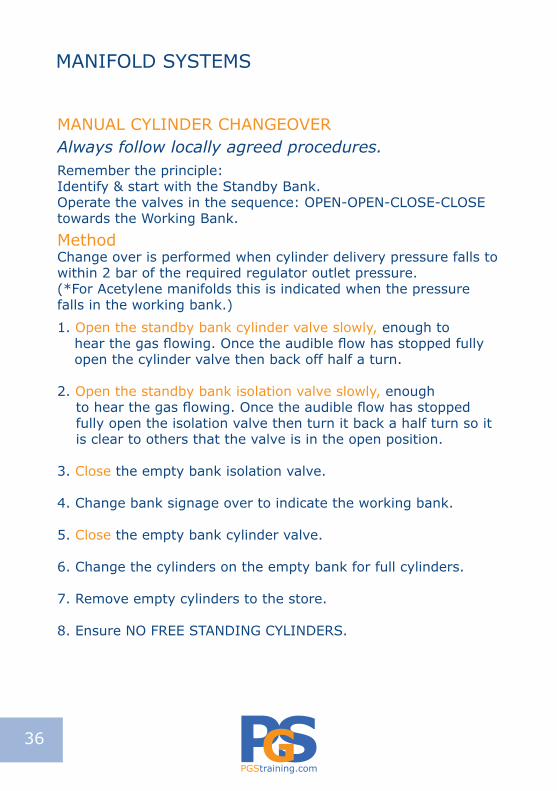
MANUAL CYLINDER CHANGEOVERAlways follow locally agreed procedures.Remember the principle: Identify & start with the Standby Bank. Operate the valves in the sequence: OPEN-OPEN-CLOSE-CLOSE towards the Working Bank.
Method Change over is performed when cylinder delivery pressure falls to within 2 bar of the required regulator outlet pressure. (*For Acetylene manifolds this is indicated when the pressure falls in the working bank.)
1. Open the standby bank cylinder valve slowly, enough tohear the gas flowing. Once the audible flow has stopped fully open the cylinder valve then back off half a turn.
2. Open the standby bank isolation valve slowly, enoughto hear the gas flowing. Once the audible flow has stopped fully open the isolation valve then turn it back a half turn so it is clear to others that the valve is in the open position.
3. Close the empty bank isolation valve.
4. Change bank signage over to indicate the working bank.
5. Close the empty bank cylinder valve.
6. Change the cylinders on the empty bank for full cylinders.
7. Remove empty cylinders to the store.
8. Ensure NO FREE STANDING CYLINDERS.
MANIFOLD SYSTEMS
36
PGStraining.com
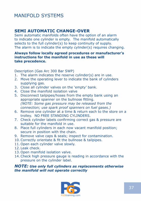
SEMI AuTOMATIC ChANGE-OVERSemi automatic manifolds often have the option of an alarm to indicate one cylinder is empty. The manifold automatically selects to the full cylinder(s) to keep continuity of supply. The alarm is to indicate the empty cylinder(s) requires changing.
Always follow locally agreed procedures or manufacturer’s instructions for the manifold in use as these will take precedence.
Description (Gas Arc 300 Bar SWP) 1. The alarm indicates the reserve cylinder(s) are in use.2. Move the operating lever to indicate the bank of cylinders
supplying gas.3. Close all cylinder valves on the ‘empty’ bank.4. Close the manifold isolation valve 5. Disconnect tailpipes/hoses from the empty bank using an
appropriate spanner on the bullnose fitting. (NOTE: Some gas pressure may be released from the connection; use spark proof spanners on fuel gases.)
6. Remove one cylinder at a time & return each to the store on a trolley. NO FREE STANDING CYLINDERS.
7. Check cylinder labels confirming correct gas & pressure are suitable for the manifold in use.
8. Place full cylinders in each now vacant manifold position; secure in position with the chain.
9. Remove valve caps & seals; inspect for contamination.10. Correctly orientate & fit the bullnose & tailpipes.11. Open each cylinder valve slowly. 12. Leak check. 13. Open manifold isolation valve.14. Check high pressure gauge is reading in accordance with the
pressure on the cylinder label.
NOTE: Use only full cylinders as replacements otherwise the manifold will not operate correctly
MANIFOLD SYSTEMS
37

PGStraining.com
WEEKLy ChECKLISTVisually Check EquipmentIn good order & being used correctly.
Framework & ChainsIn good condition.
Flexible Hoses & Pigtails No sign of damage
ValvesShut off & open correctly.
RegulatorsCorrect types are being used for the pressures & gases in use.Operate correctly in open & shut positions as appropriate.Undamaged.
Leaks No indications of:
Pressure dropSmells of gasOther signs of gas loss e.g. unaccounted large usage
Oil & Combustible MaterialManifold area is free from contaminants & combustible material.
Incorrect Use of AreaStorage of materials or other incorrect use of manifold room.
MANIFOLD SYSTEMS
38

PGStraining.com
Cylinder data sheets should be available which give the weights & types of cylinders.
HandlingBe aware of milk churning techniques & their use over short distances.
TrolleysSuitable, regularly checked & maintained trolleys should be provided.
Cylinders Be familiar with the peculiarities of handling cylinders:
Inherent instability WeightShape Valve & guard arrangement
Personal Protective Equipment Wear protective footwear, gloves & goggles when handling cylinders. (This includes management & laboratory staff!)
Lifting Equipment Can lifting equipment be provided for use as a suitable alternative to manual handling? Cylinders must not be lifted by crane or similar device without the use of a supporting guard & a guard cap/bell in place.
Ledges, Lips & StepsCheck if you have to lift cylinders onto or over:
Cylinder retaining stands Poorly designed trolleysPallet lips Large or small concrete sillsSteps/Ledges
Can alternatives be found? This also applies to inside & outside of the stores area & point of use.
CYLINDER HANDLING
39
PGStraining.com
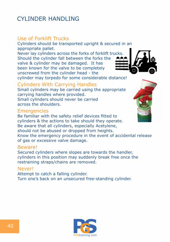
Use of Forklift TrucksCylinders should be transported upright & secured in an appropriate pallet.Never lay cylinders across the forks of forklift trucks.Should the cylinder fall between the forks the valve & cylinder may be damaged. It has been known for the valve to be completely unscrewed from the cylinder head - the cylinder may torpedo for some considerable distance!
Cylinders With Carrying HandlesSmall cylinders may be carried using the appropriate carrying handles where provided.Small cylinders should never be carried across the shoulders.
EmergenciesBe familiar with the safety relief devices fitted to cylinders & the actions to take should they operate.Be aware that all cylinders, especially Acetylene, should not be abused or dropped from heights. Know the emergency procedure in the event of accidental release of gas or excessive valve damage.
Beware!Secured cylinders where slopes are towards the handler,cylinders in this position may suddenly break free once the restraining straps/chains are removed.
Never!Attempt to catch a falling cylinder.Turn one’s back on an unsecured free-standing cylinder.
CYLINDER HANDLING
40

PGStraining.com
Ventilation The store should be well-ventilated, preferably outside & in open air.At least 50% of the perimeter of the storage area should be unobstructed to allow the free flow of air; this may be relaxed for small quantities, if in doubt contact supplier.Storage of gas cylinders indoors requires great care & you are advised to contact your gas supplier.
SignageDesignated as follows:
NO SMOKING areaNo unauthorised personnelFire-fighting equipmentGases by type
Inert & Oxygen/Flammable/Propane/Toxic/HydrogenFull & empty cylinders should be stored separately & signed accordingly. Refer to storage diagram Page 45 for further information.
Fire-fightingThe store should have adequate fire-fighting facilities.At least one 9 kilograms dry powder fire extinguisher at the entrance to the store.
LocationAt least 1 metre from site boundary.Give due regard to low-lying areas such as drains, ducts, trenches, pits & basements where heavier than air gases may accumulate creating hazardous conditions.Ensure emergency services can gain access to deal with any incident.To reduce manual handling distances check if the store could be relocated. Ensure the floor is level to prevent cylinders toppling.
GAS STORES
41

PGStraining.com
Construction ConsiderationsIs the store constructed of non-combustible material?Is fencing of industrial type & equivalent to 1.8 metres high?Is provision made for the suitable securing of gas cylinders? (Typically racking or chain arrangements)Does the store have suitable exits with outward opening panic bars?Are emergency exits unobstructed at all times?Is adequate lighting provided for the reading of cylinder labels?Are electrical fittings intrinsically safe?Are electrical appliances placed at a suitable distance & protected? (Refer to Page 44 for instruction)Consider crash barriers to offer protection from forklift trucks or vehicle impacts - risk assess.Is the stores area free from standing water or other hazards or obstructions?Are cylinders required to be lifted manually over lips or edges - risk assess? Consider ramps or lowering or raising of surfaces.
Carbon Dioxide CylindersThese cylinders are best protected from sunlight.
Toxic GasesKeep toxic gases in a well ventilated, locked enclosure with access restricted to authorised personnel.Refer to the distance table Page 44
GAS STORES
42
PGStraining.com
GAS STORES
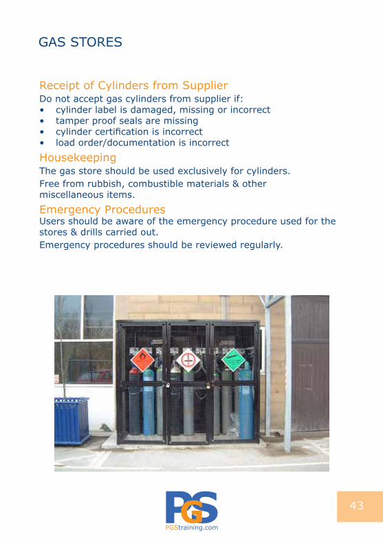
Receipt of Cylinders from SupplierDo not accept gas cylinders from supplier if:• cylinder label is damaged, missing or incorrect• tamper proof seals are missing• cylinder certification is incorrect • load order/documentation is incorrect
HousekeepingThe gas store should be used exclusively for cylinders.Free from rubbish, combustible materials & other miscellaneous items.
Emergency ProceduresUsers should be aware of the emergency procedure used for the stores & drills carried out.Emergency procedures should be reviewed regularly.
43

PGStraining.com
LPG - Guide to Minimum Separation Distances
Note 1 The distance x is dependent on the total quantity of LPG stored or the larger stack size. Use whichever result gives the greatest distance.Note 2 LPG cylinders should not be stored closer than 1.5 metres to a firewall if provided. The 1.5 metres need not be applied when the quantity is no more than 400 kilograms &:
** A minimum of 2 metres is permissible 3 metres is preferable *** 8 metres minimum if building houses a vulnerable population
GAS STORES
Public boundaryPublic accessAny building ***Fixed ignition sourceSmokingCombustible materials
Highly flammable liquidVehicles under occupiers controlBulk LPG vessels <5000 litresDrain, cellar, pitBuilding opening **
Liquid Oxygen storage tankBulk LPG vessel > 5000 litres
7.5 metres
3 metres
x metres
1. LPG is storedin a corner between two walls
2. LPG is storedbetween twowinged walls
44
PGStraining.com
GAS STORES
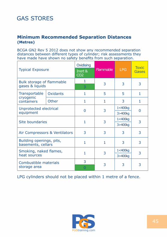
Minimum Recommended Separation distances (Metres)
BCGA GN2 Rev 5 2012 does not show any recommended separation distances between different types of cylinder; risk assessments they have made have shown no safety benefits from such separation.
Typical ExposureOxidising
Flammable LPG Toxic GasesInert &
CO2
Bulk storage of flammable gases & liquids
13 3 3
3
Transportable cryogenic containers
Oxidants 1 5 5 1
Other 1 1 3 1
Unprotected electrical equipment 0 3
1<400kg0
3>400kg
Site boundaries 1 31<400kg
33>400kg
Air Compressors & Ventilators 3 3 3 3
Building openings, pits, basements, cellars 1 1 3 3
Smoking, naked flames, heat sources 1 3
1<400kg3
3>400kg
Combustible materials storage area
33 3 3
0
LPG cylinders should not be placed within 1 metre of a fence.
45

PGStraining.com
Typical Toxic/Corrosive Storage Area
Typical Oxy/Fuel Storage Area
Fire FightingAt least one 9kg dry powder extinguisher at the entrance
Where access is required a 0.6 metre gap is suggested between full & empty cylinders. Propane < 50 kg no specific separation defined.50 - 1,000 kg diagram distances apply.> 1,000 kg refer to UKLPG Code of Practice 7. Empties are classed as full.Retail & domestic refer to UKLPG Code of Practice 7.
GAS STORES
46
PGStraining.com
Vehicle Type:1. Vehicles Used Solely for Transporting CylindersWhere possible vehicles should have an open load space e.g. pick-up truck.
Where this is not possible, the load space should be well ventilated. Under ADR 2009, open windows & vehicle fan-assisted ventilation are not adequate.
If an unventilated vehicle is used the loading doors must be signed:
WARNING: NO VENTILATION OPEN WITh CAuTION2. Mobile Workshops & Service VehiclesSpecific ventilation requirements are outlined for these vehicles including: • Minimum ventilator area of 2% of the vehicle floor area. • Fixed non adjustable ventilation at low level.• Fixed vent, preferably a roof spinner or similar, at high level • Ventilation should be equally divided between front & rear of
the vehicle. Toxic gas must not be carried in closed vehicles unless they are specifically designed for this purpose.
Mobile WorkshopsThese are vehicles where cylinders are carried for specific work processes & they are used on or near the vehicle. These processes typically involve welding, testing & laboratory functions, & can utilise a wide variety of gases.Hot work should be carried out outside the vehicle compartment. Fire extinguishers should be located nearby & exit routes should be clear of obstructions. Consider additional ventilation for the comfort & safety of persons in the vehicle.
TRANSPORTING GAS CYLINDERS BY ROAD
47
PGStraining.com
Special Site Service VehiclesThese are vehicles with cylinder installations supplying appliances such as those used for cooking, heating or lighting facilities.
The gas normally used is Propane or Butane.
Ensure appliances are manufactured to the appropriate British Standards & installed according to the manufacturer’s instructions.
Each appliance should have a gas isolation valve for use during maintenance or for emergency shut off.
Appliances should not be lit during transit.(Refrigerators with flame failure devices are acceptable).
Catering devices should not be left unattended when in use.
Cylinder Segregation from Driver Where cylinders to be used off the vehicle are carried within a closed vehicle, the load compartment should be separated from the driver’s cab by a gas-tight bulkhead. This should be constructed & secured so as to protect the driver from cylinder impact in the event of a road traffic accident.
Fire Extinguishers The Law for small vehicles & vans requires a suitable 2 Kg Fire Extinguisher to be carried on the vehicle; CO2 or Dry Powder type Extinguishers are suitable for Flammable & Oxidising gases.
Vehicle Maintenance The vehicle must comply with statutory requirements when in use & be properly maintained. Records of maintenance should be kept.
Vehicle DocumentationThe documentation required for a journey may vary according to the quantity & type of gas cylinders carried. (See Page 51-52)
TRANSPORTING GAS CYLINDERS BY ROAD
48

PGStraining.com
Vehicle Signage It is not a legal requirement to display hazard-warning signs on the vehicle when the load carried is below the Threshold Quantity.
It is good practice to display appropriate warning signs on the vehicle whenever gas cylinders are carried; the signs must be removed once the cylinders have been unloaded.
Driver Training Regardless of load quantity any driver carrying gas cylinders should should be:• Trained in the hazards & properties of the gases they carry. • Trained in the safe use & handling of the gases they carry. • Trained in the use of vehicle Fire Fighting Equipment. • Conversant with CDG 2009 & relevant Emergency Procedures.
Note: ADR training is required for drivers of vehicles below 3.5 tonnes if the load Threshold Calculation shows that limiting quantities will be exceeded.
Emergency Procedures Drivers should be fully conversant with the Emergency Procedures adopted by the company in the case of: • Vehicle accident.• Incidents involving gas cylinders in fires.• Incidents involving gas escapes.• Evacuation distances & drills.• Actions regarding Acetylene cylinders involved in fires.
TRANSPORTING GAS CYLINDERS BY ROAD
49

PGStraining.com
Before commencing a journey when gas cylinders are to be carried, the driver should check the following:
Cylinders Cylinder Valves are closed.Preferably equipment disconnected from cylinders. Leak checked before the journey.Correctly labelled.Propane cylinders should be carried in an upright position at all times. (Refer to UKLPG CP27 for information on the transportation of Propane)In a closed vehicle cylinders should be loaded in a single layer & constrained to prevent any movement or displacement.It is strongly recommended that all cylinders are carried upright & secured.Where fitted, gas tight plugs should be in place. Where more than four LPG cylinders are carried the driver should carry sufficient spare plugs or caps for use where they are missing on returned cylinders.Cylinders should not project beyond the side or back of the vehicle.
Vehicle Appropriate for use.Within weight limits.Road worthy.Engine stopped for loading & unloading.Vehicle crew only no passengers.Ventilation points free from debris & uncovered.NO SMOKING allowed.
Driver Trained in emergency procedures.Training current.
TRANSPORTING GAS CYLINDERS BY ROADBEFORE JOURNEY CHECKS
50
PGStraining.com
Carriage of Dangerous Goods Regulations CDGR/ADRThe following information on pages 50-52 is required for all journeys under the load threshold limit as is the driver training requirements see page 48.
If the load exceeds the load threshold limit, the full requirements of ADR apply & the driver must:
Carry Consignor Information & Information in Writing Be trained to ADR standardsDisplay an orange plate on the vehicleCarry first-aid & fire fighting equipmentConsult the latest CDGR & ADR regulations
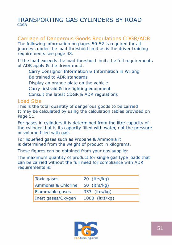
Load Size This is the total quantity of dangerous goods to be carriedIt may be calculated by using the calculation tables provided on Page 51.For gases in cylinders it is determined from the litre capacity of the cylinder that is its capacity filled with water, not the pressure or volume filled with gas.For liquefied gases such as Propane & Ammonia itis determined from the weight of product in kilograms.These figures can be obtained from your gas supplier.The maximum quantity of product for single gas type loads that can be carried without the full need for compliance with ADR requirements is:
Toxic gases 20 (ltrs/kg)Ammonia & Chlorine 50 (ltrs/kg)Flammable gases 333 (ltrs/kg)Inert gases/Oxygen 1000 (ltrs/kg)
TRANSPORTING GAS CYLINDERS BY ROADCDGR
51

PGStraining.com
Calculating LoadThe following information is required:1. Transport Category 2. Quantity in kilograms or litres of the gases determined by the
cylinder size/number of cylinders which then equates to points This is then used on the calculator table (example below) The table works by determining the total load size by using a multiplier to reflect the hazard category of the product:
Transport Category Gas Category Multiplier
Quantity x Load Size
1 Toxic 50 A
2 Flammable 3 B
3 Asphyxiant /Oxidising 1 C
Load Size = A + B + C
If the load size A + B + C exceeds 1,000 ltr/kg (points) the full operational provisions of ADR apply to the journeyExample of a Completed Load Table:
a b c d e f
Gas type Transport Category
Cylinder Size
Number of Cylinders
Multiplier(50, 3 or 1)
Load size=c x d x e
Propane 2 47 2 3 282
Propane 2 18 2 3 108
Nitrogen 3 50 1 1 50
Oxygen 3 50 1 1 50
Total 490 points
For Acetylene, Propane, liquefied gases & refrigerants the net mass of gas in kg is used, this will be available from your gas supplier & will vary according to cylinder size.It is strongly recommended that drivers carry with them Instructions in Writing available from www.iru.org & Gas Data Sheets available from gas supplier for the products being carried. These are mandatory where the load threshold has been exceeded & the full requirements of ADR apply.
TRANSPORTING GAS CYLINDERS BY ROADCALCULATING LOAD
52
PGStraining.com
TRANSPORTING GAS CYLINDERS BY ROADCALCULATING ROAD
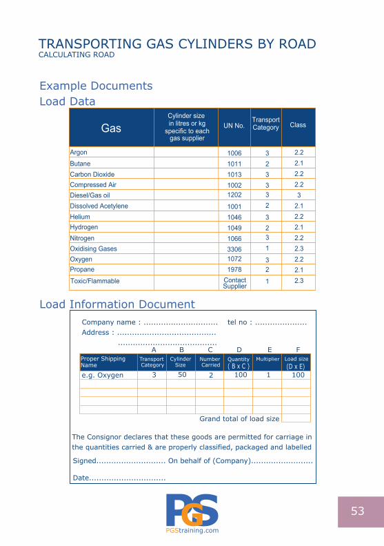
Example DocumentsLoad Data
Load Information Document
Cylinder size in litres or kg
specific to eachgas supplier
Gas UN No.TransportCategory Class
Butane Carbon DioxideCompressed AirDiesel/Gas oilDissolved Acetylene
HydrogenNitrogenOxidising Gases
Propane
Toxic/Flammable
10061011101310021202
1001104610491066330610721978
ContactSupplier
3
33
3
32
2
23
32
1
1
2.2
2.2
2.2
2.2
2.2
2.2
2.1
2.1
2.1
2.1
2.3
2.3
3
Helium
Oxygen
Argon
Company name : .............................. tel no : .....................Address : ........................................ ........................................
Load size(D x E)
Proper ShippingName
Transport Category
CylinderSize
Quantity( B x C )
MultiplierNumber Carried
e.g. Oxygen 3 50 2 100 1 100
A B C D E F
The Consignor declares that these goods are permitted for carriage inthe quantities carried & are properly classified, packaged and labelled
Signed............................ On behalf of (Company).........................
Date...............................
Grand total of load size
53

PGStraining.com
NOTES