Embed Size (px)
Citation preview
Home"" """"> ar.cn.de.en.es.fr.id.it.ph.po.ru.sw
Compressed Earth Blocks - Volume II. Manual of design and
construction (GTZ, 1995, 148 p.)
(introduction...)
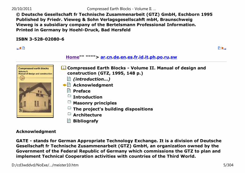
Acknowledgment
Preface
Introduction
Historical background
Advantages of CEBS
Production
The CEB as a building material
Main characteristics
A building tradition
The exposed wall's harmonious appearance
Architecture for housing
Architecture for public buildings
Masonry principles
(introduction...)
Mortar
Bonding patterns
Coursing
The project's building dispositions
20/10/2011 Compressed Earth Blocks - Volume II. …
D:/cd3wddvd/NoExe/…/meister10.htm 1/304
(introduction...)Types of wall
Types of structure
Foundations and footings
Openings
Reinforcement
Floors: structures
Jack arches and vaulting
Roof classification
Finishings
Installing technical systems
Characteristic strength of CEBS
Safety and height to width coefficients
Permissible constraints
Building economics
Architecture
Architectural achievements or projects
Architecture for housing
Architecture for public buildings
Bibliografy
Home"" """"> ar.cn.de.en.es.fr.id.it.ph.po.ru.sw
Compressed Earth Blocks - Volume II. Manual of design and
construction (GTZ, 1995, 148 p.)
20/10/2011 Compressed Earth Blocks - Volume II. …
D:/cd3wddvd/NoExe/…/meister10.htm 2/304
(introduction...)Acknowledgment
Preface
Introduction
Masonry principles
The project's building dispositions
Architecture
Bibliografy
Compressed earth blocks
Volume II. Manual of design and construction
A Publication of the Deutsches Zentrum fr Entwicklungstechnologien - GATE in: Deutsche
Gesellschaft fr Technische Zusammenarbeit (GTZ) GmbH in coordination with BASIN -
1985
Hubert Guillaud, Thierry Joffroy, Pascal Odul, CRATerre- EAG
Scientific supervision: Patrice Doat, teaching architect; Hubert Guillaud, research engineer
Authors: Hubert Guillaud, research architect; Pascal Odul, engineer architect; Thierry
Joffroy, architect
Illustrations: Oscar Salazar, architect; Patrick Idelman, draughtsman
Documentation: Marie-France Ruault
Format: Rgine Rivire
English Translation: Claire Norton
Publishing coordination: Titane Galer
20/10/2011 Compressed Earth Blocks - Volume II. …
D:/cd3wddvd/NoExe/…/meister10.htm 3/304
© Photographs
CRATerre-EAG: Dario Abgulo, Patrice Doat, Sbastien d’Ornano, Hubert Guillaud, Hugo
Houben, Thierry Joffroy, Serge Mani, Pascal Odul, Vincent Rigassi and additional
assistance from: Sylvian Arnoux, Patrick Bolle, Anne-Sophie Clmenon, Christian Lignon,
Christophe Magne, Philippe Romagnolo, Olivier Scherrer
© Drawings: CRATerre-EAG
Cover photograph (Fig. 1): Rented house, Mayotte, Built by SIM.
Die Deutsche Bibliothek - CIP-Einheitsaufnahme
Compressed earth blocks:
A publication of Deutsches Zentrum fr Entwicklungstechnologien - GATE, a division of the
Deutsche Gessellshaft fr Technische Zusammenarbeit (GTZ) GmbH in coordination with
the Building Advisory Service and Information Network - BASIN / (Engl. Transl.: Claire
Norton). - Braunschweig: Vieweg.
NE: Norton, Claire (bers.); Deutsches Zentrum fr Entwicklungstechnologien <Eschborn>
Vol. 2. Manual of design and construction / Hubert Guillaud... (III.: Oscar Salazar; Patrick
Idelman). - 1995
ISBN 3-528-02080-6
NE: Guillaud, Hubert
With the help of Architectural Research staff of the Department of Architecture and
Urbanism (Direction de l’Architecture et de l’Urbanisme - DAU) du Ministre de
l’Equipment, du Logement et des Transports
All rights reserved
20/10/2011 Compressed Earth Blocks - Volume II. …
D:/cd3wddvd/NoExe/…/meister10.htm 4/304
© Deutsche Gesellschaft fr Technische Zusammenarbeit (GTZ) GmbH, Eschborn 1995
Published by Friedr. Vieweg & Sohn Verlagsgesellscahft mbH, Braunschweig
Vieweg is a subsidiary company of the Bertelsmann Professional Information.
Printed in Germany by Hoehl-Druck, Bad Hersfeld
ISBN 3-528-02080-6
Home"" """"> ar.cn.de.en.es.fr.id.it.ph.po.ru.sw
Compressed Earth Blocks - Volume II. Manual of design and
construction (GTZ, 1995, 148 p.)
(introduction...)
Acknowledgment
Preface
Introduction
Masonry principles
The project's building dispositions
Architecture
Bibliografy
Acknowledgment
GATE - stands for German Appropriate Technology Exchange. It is a division of Deutsche
Gesellschaft fr Technische Zusammenarbeit (GTZ) GmbH, an organization owned by the
Government of the Federal Republic of Germany which commissions the GTZ to plan and
implement Technical Cooperation activities with countries of the Third World.
20/10/2011 Compressed Earth Blocks - Volume II. …
D:/cd3wddvd/NoExe/…/meister10.htm 5/304
GATE was established in 1978 on behalf of the German Federal Ministry for Economic
Cooperation (BMZ) - which is responsible for development cooperation with Third World
countries - and in consultation with the German Federal Ministry for Research and
Technology (BMFT).
GATE currently works in the fields of dissemination of appropriate technologies,
environmental protection and conservation of natural resources. Within the GTZ, GATE is
responsible for these activities on a cross-sectoral basis. GATE, with the "Information
Service on Appropriate Technology (ISAT)" works in the following areas:
1) Dissemination of appropriate technologies
Dissemination and application of appropriate technologies, especially in connection with
self-help activities
- Cooperation with non-governmental appropriate technology groups: cooperation with
NGO's in Africa, Asia, Oceania and Latin America.
- Information service: documentation (appropriate technologies), exchange of
information, question and answer service, publication of technical brochures, articles and
a technical journal.
- Fund for small-scale appropriate technology projects.
2) Environmental protection and conservation of natural resources
- Coordination of environmental protection activities at the GTZ.
- Further development of methods and instruments for environmental impact assessment.
- Technical backstopping and coordination of interdisciplinary and multisectoral projects
20/10/2011 Compressed Earth Blocks - Volume II. …
D:/cd3wddvd/NoExe/…/meister10.htm 6/304
in the fields of environmental protection and conservation of natural resources.
- Cooperation with the relevant national and international organizations, associations and
offices concerned with this sector.
German Appropriate Technology Exchange - GATE in: Deutsche Gesellschaft fur Technische
Zusammenarbeit (GTZ) GmbH Posffach 5180 / D-65726 Eschborn / Germany / Phone:
(06196) 79-0 / Telex: 407 501 0 gtz d / Fax (06196) 79 48 20
CRATerre-EAG - The International Centre for Earth Construction - School of Architecture of
Grenoble. The members of CRATerreEAG are high-level professionals from various
countries. Since 1973, CRATerre-EAG has been involved full time in all aspects of earthen
architecture from the preservation of historic monuments to the setting up of modern
production lines. CRATerre-EAG's five inter-related fields of activity are:
1) Research: as an officially recognized research team, CRATerre-EAG carries out several
research programs at fundamental and practical levels in various fields such as ethnology,
economy, mineralogy, soil mechanics, technology, etc.
2) Consultancy: CRATerre-EAG's missions in this field cover the project formulation,
feasibility and investment studies, setting up of programs, building design, raw material
prospection, planning and evaluation.
3) Application: CRATerre-EAG members are currently engaged in field operations from
architectural design to site supervision of social or educational building on behalf of
governmental or non-governmental organizations.
4) Training: in collaboration with the School of Architecture of Grenoble (EAG) and
Grenoble University (USTMG), CRATerre-EAG runs post-graduate courses for architects
and building engineers. CRATerre-EAG also organizes vocational training courses and
20/10/2011 Compressed Earth Blocks - Volume II. …
D:/cd3wddvd/NoExe/…/meister10.htm 7/304
thematic intensive training sessions in collaboration with organizations such as the
International Union of Testing and Research Laboratories for Materials and Structures
(RILEM), International Council for Building Research Studies and Documentation (ClB),
United Nations Industrial Development Organization (UNIDO), International Centre for the
Study of the Preservation and Restoration of Cultural Property (ICCROM) and others.
5) Dissemination: through the publication of scientific and technical books and manuals,
an active participation in international meetings and a "question-and-answer" service,
CRATerre-EAG contributes greatly to the promotion of earthen architecture and the
dissemination of technical information.
CRATerre-EAG
Maison Levrat / Parc Fallavier / BP 53 / F - 38092 Villefontaine Cedex / France / Telex:
308 658 F / Fax: (33) 74 95 64 21
Scientific supervision: Patrice Doat, teaching architect; Hubert Guillaud, research
architect; Hugo Houben, research engineer
Authors: Hubert Guillaud, research architekt; Pascal Odul, engineer architect; Thierry
Joffroy, architect
Additional assistance: Vincent Rigassi, architect; Alexandra Douline, senior technician;
Philippe Gamier, architect
Illustrations: Oscar Salazar, architect; Patrick Idelman, draughtsman
Documentation: Marie-France Ruault
Format: Rgine Rivire
20/10/2011 Compressed Earth Blocks - Volume II. …
D:/cd3wddvd/NoExe/…/meister10.htm 8/304
English Translation: Claire Norton
Publishing coordination: Titane Galer
Photographs
CRATerre-EAG: Dario Angulo, Patrice Doat, Sbastien d'Ornano, Alexandre Douline, Hubert
Guillaud, Hugo Houben
Thierry Joffroy, Serge Mani, Pascal Odul, Vincent Rigassi and additional assistance from:
Sylvain Arnoux, Patrick Bolle,
Anne-Sophie Clemencon, Christian Lignon, Christophe Magne, Philippe Romagnolo, Olivier
Scherrer
Drawings: CRATerre-EAG
Cover photograph (Fig. 1): Rented house, Mayotte. Built by SIM.
Die Deutsche Bibliothek- CIP-Einheitsaufnahme
Compressed earth blocks: A publication of Deutsches Zentrum fur
Entwicklungstechnologien - GATE, a division of the Deutsche Gesellschaft fur Technische
Zusammenarbeit (GTZ) GmbH in coordination with the Building Advisory Service and
Information Network - BASIN / (Engl. transl.: Claire Norton). - Braunschweig: Vieweg. NE:
Norton, Claire (Ubers.); Deutsches Zentrum fr Entwicklungstechnologien <Eschborn>
Vol. 2. Manual of design and construction / Hubert Guillaud... (111.: Oscar Salazar; Patrick
Idelman). - 1995
ISBN 3-528-02080-6
NE: Guillaud, Hubert
With the help of Architectural Research staff of the Department of Architecture and
20/10/2011 Compressed Earth Blocks - Volume II. …
D:/cd3wddvd/NoExe/…/meister10.htm 9/304
Urbanism (Direction de l'Architecture et de l'Urbanisme - DAU) du Ministre de
l'Equipement, du Logement et des Transports
All rights reserved
© Deutsche Gesellschaft fr Technische Zusammenarbeit (GTZ) GmbH, Eschborn 1995
Published by Friedr. Vieweg & Sohn Verlagsgesellschaft mbH, Braunschweig
Vieweg is a subsidiary company of the Bertelsmann Professional Information.
Printed in Germany by Hoehl-Druck, Bad Hersfeld
ISBN 3-528-02080-6
This book is the fruit of patient and methodical team-work carried out in the course of
fifteen years of scientific and technical research, within the CRATerre research laboratory
of the School of Architecture of Grenoble, on compressed earth block technology and its
architectural applications, closely linked to experimentation and to site-work, as well as to
university teaching and professional training. Designed with the intention of widely
disseminating theoretical knowledge as well as practical skills, a large part of the book is
devoted to practical examples of construction techniques and architectural design, which
are the central themes. It is important to provide a wider public of land-use decision-
makers, architects and engineers, entrepreneurs and builders, with the information and
tools needed to ensure a high quality of architectural application, which alone can ensure
the social, cultural and political acceptance of this technology.
With its attractive layout and the answers it provides to all the practical questions that
site practitioners might ask, this book seeks to impart confidence in a construction
technology, which is still historically young and not sufficiently known. It emphasizes the
link between building material, structure, form, and architectural detailing. But it also
addresses the importance of the technology with regard to economic and social benefits
20/10/2011 Compressed Earth Blocks - Volume II. …
D:/cd3wddvd/NoExe/…/meister10.htm 10/304
for the local population, as are confirmed by some of the project examples presented in it.
"A building material is interesting not for what it is, but for what it can do for society."
John Tumer's aphorism remains remarkably relevant today, and, in many situations, the
compressed earth block has already proved its ability to play a significant role in providing
affordable and decent shelter for all levels of society. The reader of this will be a
committed practitioner with a better understanding of the technology of compressed earth
blocks and ready to play a useful role in society.
Home"" """"> ar.cn.de.en.es.fr.id.it.ph.po.ru.sw
Compressed Earth Blocks - Volume II. Manual of design and
construction (GTZ, 1995, 148 p.)
(introduction...)
Acknowledgment
Preface
Introduction
Masonry principles
The project's building dispositions
Architecture
Bibliografy
Preface
Compressed earth block technology, which is anchored in an initial concern to provide a
new, economically and socially relevant response to housing production for the very poor,
20/10/2011 Compressed Earth Blocks - Volume II. …
D:/cd3wddvd/NoExe/…/meister10.htm 11/304
has continued to focus on this concern as its area of application has developed. Tens of
thousands of family or communal homes and educational and health facilities have indeed
been built since the early 1950s, when this building material emerged in its present form,
at the CINVA Centre in Bogota, Colombia. These buildings have gradually confirmed the
appropriation of this building technology. This simple building material, directly
descended from the most ancient building traditions of the unbaked earth brick and from
the fired brick, is capable of the same building and architectural subtlety and the same
capacity for adaptation to the broad spectrum of factors - physical, ecological, social,
economic and technical -which dictate the production of the built environment. As a
building material, it has come to the fore by demonstrating its usefulness, which can be
measured in technical and economic, but also in human terms. From a technical point of
view, compressed earth block technology is firmly propped up by a scientific body of
knowledge which is the equal of knowledge developed for other kindred building materials
used in masonry. From an economic point of view, the compressed earth block, which has
the advantage of being able to be locally produced and directly used, is today comparable
and sometimes more competitive, depending on the context in which it is applied. As far
as production and construction distribution chains are concerned, the technology
generates employment across a wide range of jobs, from quarrying to brick-
manufacturing, from builder to entrepreneur. In architectural terms, the compressed earth
block ensures high quality results and at the same time, given optimum conditions of use,
enables the foreign currency and energy savings which are essential to its relevance from
a development point of view. At a human level, this technology provides concrete
responses to the basic issue of improving the built environment and therefore the well-
being of societies. Better quality construction and architecture, accessibility and
replicability are the main criteria for evaluating this relevance from a human and economic
view-point. But this relevance is possible only if the scientific and technical body of
knowledge has been mastered, as well as the practical skills. This book supplies the
intellectual and practical tools required for a correct application of compressed earth block
technology in the field.
20/10/2011 Compressed Earth Blocks - Volume II. …
D:/cd3wddvd/NoExe/…/meister10.htm 12/304
This book is also the fruit of patient and methodical team work, with the underlying
objective of achieving the scientific, technical, social and cultural ratification of a new
technology, the useful potential of which was obvious from the very first. Our intuition of
this usefulness still, however, had to be confirmed. But today, we are talking about a
technology which has not only achieved a level of industrial potential with production
methods suited to the formal production sector, but also been able to remain on the scale
of craft production and safeguard a degree of usefulness which is relevant to informal
sector applications. This dual advantage can serve a wide range of architectural
applications in the field of both housing and public facilities. The success of contemporary
cases, notably the example of applications on the island of Mayotte (Comoro), confirms
this dual advantage placed at the service of development ensuring economic and social
spin-offs for the local population. This ratification needed to be confirmed by building up a
body of knowledge and skill capable of being transmitted and appropriated, starting from
high quality architectural examples. This is in fact what has in many instances occured, as
is shown in the monographs which form the second part of this book, a book intended as
much for land-use decision-makers as for architects, engineers or entrepreneurs; a book
designed to boost confidence and supply the practical tools which seem to us, at the term
of our research and field experience, indispensable; a book designed to disseminate this
knowledge and skill towards a wider area of application, but most particularly towards
housing and public facilities for local communities who have no choice but to use earth as
a basic building material and who have a legitimate desire to benefit from modern
technology. Such is compressed earth block technology, at the crossroads between
traditional earth building customs and modern masonry building practices, a technology
which offers an alternative whilst remaining within a range of high quality architectural
applications.
This book has been made possible thanks to the active collaboration which has developed
over recent years between our team and the international non-government organisation
MISEREOR and with GATE/GTZ (German cooperation) in the field of dissemination of
20/10/2011 Compressed Earth Blocks - Volume II. …
D:/cd3wddvd/NoExe/…/meister10.htm 13/304
appropriate building technologies, through training and pilot architectural applications.
Our particular/hanks are due to Mr. Herbert Mathissen and Mrs. Hannah Schreckenbach,
from these two organisations respectively, for the help they have given us with the
preparation of the book as well as for the trust which they have placed in their authors in
order for the project to succeed. We also wish to thank all those involved in the field -
architects, entrepreneurs, builders and brick-makers - who have enabled the
implementations of compressed earth block architecture, which are given as examples in
this book, to occur and thus strengthened the potential, in terms of usefulness and quality,
of this technology. May their example be followed by yet more practitioners following on
in the same spirit as their predecessors, whose intention today is to share their knowledge
and experience.
Hubert Guillaud, Hugo Houben, CRATerre-EAG researchers.
Home"" """"> ar.cn.de.en.es.fr.id.it.ph.po.ru.sw
Compressed Earth Blocks - Volume II. Manual of design and
construction (GTZ, 1995, 148 p.)
Introduction
Historical background
Advantages of CEBS
Production
The CEB as a building material
Main characteristics
A building tradition
20/10/2011 Compressed Earth Blocks - Volume II. …
D:/cd3wddvd/NoExe/…/meister10.htm 14/304
The exposed wall's harmonious appearanceArchitecture for housing
Architecture for public buildings
Compressed Earth Blocks - Volume II. Manual of design and construction (GTZ, 1995, 148
p.)
Introduction
Historical background
The compressed earth block is the modern descendent of the moulded earth block, more
commonly known as the adobe block. The idea of compacting earth to improve the quality
and performance of moulded earth blocks is, however, far from new, and it was with
wooden tamps that the first compressed earth blocks were produced. This process is still
used in some parts of the world. The first machines for compressing earth probably date
from the 1 8th century. In France, Francois Cointeraux, inventor and fervent advocate of
"new pise" (rammed earth) designed the "crecise", a device derived from a wine-press.
But it was not until the beginning of the 20th century that the first mechanical presses,
using heavy lids forced down into moulds, were designed. Some examples of this kind of
press were even motor-driven. The fired brick industry went on to use static compression
presses in which the earth is compressed between two converging plates. But the turning
point in the use of presses and in the way in which compressed earth blocks were used for
building and architectural purposes came only with effect from 1952, following the
invention of the famous little CINVA-RAM press, designed by engineer Raul Ramirez at the
ClNVA centre in Bogota, Columbia. This was to be used throughout the world. With the
'70s and'80s there appeared a new generation of manual, mechanical and motor-driven
presses, leading to the emergence today of a genuine market for the production and
application of the compressed earth block.
20/10/2011 Compressed Earth Blocks - Volume II. …
D:/cd3wddvd/NoExe/…/meister10.htm 15/304
A highly developed technology
Since its emergence in the '50s, compressed earth block (CEB) production technology and
its application in building has continued to progress and to prove its scientific as well as
its technical worth.
Research centres, industrialists, entrepreneurs and builders have developed a very
sophisticated body of knowledge, making this technology the equal today of competing
construction technologies. CEB production meets scientific requirements for product
quality control, from identification, selection and extraction of the earth used, to quality
assessment of the finished block, thanks to procedures and tests on the materials which
are now standardised. This scientific body of knowledge ensures the quality of the
material. Simultaneously, the accumulated experience of builders working on a very large
number of sites has also enabled architectural design principles and working practices to
emerge and today these form practical points of reference for architects and
entrepreneurs, as well as for contractors.
Role in development
The setting up of compressed earth block production units, whether on a small-scale or at
industrial level, in rural or urban contexts, is linked to the creation of employment
generating activities at each production stage, from earth extraction in quarries to
building work itself. The use of the material for social housing programmes, for
educational, cultural or medical facilities, and for administrative buildings, helps to
develop societies' economies and well-being. CEB production forms part of development
strategies for the public and the private sector which underline the need for training and
new enterprise and thus contributes to economic and social development. This was the
case in the context of a programme on the island of Mayotte, in the Comoro islands, for the
construction of housing and public buildings, a programme today regarded as an
20/10/2011 Compressed Earth Blocks - Volume II. …
D:/cd3wddvd/NoExe/…/meister10.htm 16/304
international reference. The use of CEBs which followed the setting up of an island
production industry proved to be pivotal in Mayotte's development, founded on a building
economy generating employment and local added value in monetary, economic and social
terms.
Social acceptance
CEB represents a considerable improvement over traditional earth building techniques.
When guaranteed by quality control, CEB products can very easily bear comparison with
other materials such as the sand-cement block or the fired brick. Hence the allegiance it
inspires amongst decision-makers, builders and end-users alike.
The future of CEBs
CEB technology has made great progress thanks to scientific research, to experimentation,
and to architectural achievements which form the basis of a wide range of technical
documents and academic and professional courses. A major effort is now being devoted to
the question of norms and this should help to confer ultimate legitimacy upon the
technique in the coming years.
Advantages of CEBS
The CEB technique has several advantages which deserve mention:
- The production of the material, using mechanical presses varying in design and
operation, marks a real improvement over traditional methods of producing earth blocks,
whether adobe or hand-compacted, particularly in the consistency of quality of the
products obtained. This quality furthers the social acceptance of a renewal of building with
earth.
20/10/2011 Compressed Earth Blocks - Volume II. …
D:/cd3wddvd/NoExe/…/meister10.htm 17/304
- Compressed earth block production is generally linked to the setting up of quality control
procedures which can meet requirements for building products standards, or even norms,
notably for use in urban contexts.
- In contexts where the building tradition already relies heavily on the use of small
masonry elements (fired bricks, stone sand-cement blocks), the compressed earth block is
very easily assimilated and forms an additional technological resource serving the socio-
economic development of the building sector.
- Policy-makers, investors and entrepreneurs find the flexibility of mode of production of
the compressed earth block, whether in the rural or the urban context, small-scale or
industrial, a convincing argument.
- Architects and the inhabitants of buildings erected in this material are drawn to the
architectural quality of well-designed and well-executed compressed earth block
buildings.
Technical performance
Compacting the soil using a press improves the quality of the material. Builders appreciate
the regular shape and sharp edges of the compressed earth block. The higher density
obtained thanks to compaction significantly increases the compressive strength of the
blocks, as well as their resistance to erosion and to damage from water.
Flexibility of use
The wide range of presses and production units available on the current market makes the
material very flexible to use. With production ranging from small-scale to medium and
large-scale semi-industrial or industrial, CEBs can be used in rural and urban contexts and
can meet very widely differing needs, means and objectives.
20/10/2011 Compressed Earth Blocks - Volume II. …
D:/cd3wddvd/NoExe/…/meister10.htm 18/304
Standards and models
Compressed earth blocks are of standard sizes and meet quality requirements which are
suitable for carrying out large housing or infrastructure programmes, based on the design
of architectural models. These standard block sizes and shapes, as well as the
architectural models, can be defined before the programme begins, at the design stage,
with great flexibility.
Highly practical nature of the technology
The common dimensions of CEBs lend themselves to great flexibility of use in various
building solutions, as load-bearing masonry or as in-fill. CEBs can also be used for arches,
vaults and domes, as well as for jack-arch floors.
Genuine architectural merit
Very fine masonry work, equal to fired brick building traditions, can be realised thanks to
the high quality of compressed earth blocks. The architectural application of CEBs can
range from social housing to luxury homes and prestigious public buildings. Since the
'50s, the experience of architects and builders has been considerably enriched by widely
differing architectural realisations in all areas of application. Experimentation has to a
large extent given way to technological and architectural expertise and has enabled CEB
technology to evolve to the point where today it can be considered the equal of other
construction technologies using small masonry elements.
An alternative to importation
Whilst meeting the same requirements as other present-day building materials, the CEB
also presents a technological alternative to imported materials, the use of which is often
justified because of the need for standardisation. CEBs have the advantage of being
20/10/2011 Compressed Earth Blocks - Volume II. …
D:/cd3wddvd/NoExe/…/meister10.htm 19/304
produced locally, whilst still meeting this need.
Some constraints
The quality of CEBs depends on good soil selection and preparation and on the correct
choice of production material. Architectural use of the material must take account of
specific design and application guidelines which must be applied by both architects and
builders. This means that professional skills must be ensured by suitable training. From an
economical point of view, CEBs can sometimes fail to be competitive with other local
materials. A technical-economic survey will enable the feasibility of the technology to be
determined in each application context.
Production
The production of compressed earth blocks can be regarded as similar to that of fired
earth blocks produced by compaction, except that there is no firing stage. Production will
be differently organized, depending on whether it takes place in the context of small,
"craft industry" units (or brickworks), or in the context of a semi-industrial or industrial
unit. Production, drying and stocking areas will also vary depending on the methods of
production selected and the production conditions dictated by the climatic, social,
technical and economic environment.
No production period or season is particularly favourable or unfavourable, providing that
measures are taken in wet or hot seasons (if any) to protect production areas or storage
areas.
Generally speaking, as far as production rates are concerned, these will depend largely on
the way production is organised and on the type of equipment used as well as on the skill
of the labour-force.
20/10/2011 Compressed Earth Blocks - Volume II. …
D:/cd3wddvd/NoExe/…/meister10.htm 20/304
CATEGORIES OF PRESSES
Manual presses
These are manually operated and carry out only the compression and ejection of the block.
Light, mechanical and hydraulic presses fall into this category. Production outputs for
these presses are in the order of 300 blocks per day. Mechanized manual presses also
exist, and are generally heavier and more robust, but their outputs remain hardly any
higher than that of light presses (up to 500 blocks per day).
Motorized presses
These are motor-driven and carry out only the compression and ejection of the block.
Mechanical and hydraulic presses fall into this category. Motorized mechanical presses
form a new generation of presses, sometimes derived from heavy mechanized manual
presses. They enable better rates of production and outputs can exceed 800 blocks per
day. Hydraulic motorized presses, which are descended from pumping and oil-circuit
mechanisms, should only be used in a favourable technological environment. Their
viability should be checked.
Mobile production units (light)
These are easily transportable, motorized and sometimes automated. In addition to the
compression and ejection of the block, they also carry out raw material preparation
operations and/or the removal of the products.
Fixed production units
These are difficult to transport, motorized and sometimes automated. In addition to the
compression and ejection of the block, they also carry out raw material preparation
20/10/2011 Compressed Earth Blocks - Volume II. …
D:/cd3wddvd/NoExe/…/meister10.htm 21/304
operations and/or the removal of the products.
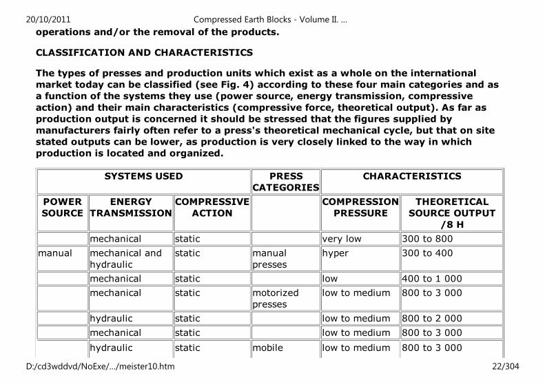
CLASSIFICATION AND CHARACTERISTICS
The types of presses and production units which exist as a whole on the international
market today can be classified (see Fig. 4) according to these four main categories and as
a function of the systems they use (power source, energy transmission, compressive
action) and their main characteristics (compressive force, theoretical output). As far as
production output is concerned it should be stressed that the figures supplied by
manufacturers fairly often refer to a press's theoretical mechanical cycle, but that on site
stated outputs can be lower, as production is very closely linked to the way in which
production is located and organized.
SYSTEMS USED PRESS
CATEGORIES
CHARACTERISTICS
POWER
SOURCE
ENERGY
TRANSMISSION
COMPRESSIVE
ACTION
COMPRESSION
PRESSURE
THEORETICAL
SOURCE OUTPUT
/8 H
mechanical static very low 300 to 800
manual mechanical and
hydraulic
static manual
presses
hyper 300 to 400
mechanical static low 400 to 1 000
mechanical static motorized
presses
low to medium 800 to 3 000
hydraulic static low to medium 800 to 2 000
mechanical static low to medium 800 to 3 000
hydraulic static mobile low to medium 800 to 3 000
20/10/2011 Compressed Earth Blocks - Volume II. …
D:/cd3wddvd/NoExe/…/meister10.htm 22/304
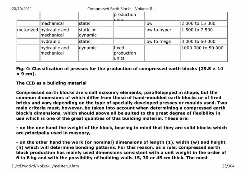
production
unitsmechanical static low 2 000 to 15 000
motorized hydraulic and
mechanical
static or
dynamic
low to hyper 1 500 to 7 500
hydraulic static low to mega 3 000 to 50 000
hydraulic and
mechanical
dynamic fixed
production
units
1000 000 to 50 000
Fig. 4: Classification of presses for the production of compressed earth blocks (29.5 × 14
× 9 cm).
The CEB as a building material
Compressed earth blocks are small masonry elements, parallelepiped in shape, but the
common dimensions of which differ from those of hand-moulded earth blocks or of fired
bricks and vary depending on the type of specially developed presses or moulds used. Two
main criteria must, however, be taken into account when determining a compressed earth
block's dimensions, which should above all be suited to the great degree of flexibility in
use which is one of the great qualities of this building material. These are:
- on the one hand the weight of the block, bearing in mind that they are solid blocks which
are principally used in masonry,
- on the other hand the work (or nominal) dimensions of length (1), width (w) and height
(h) which will determine bonding patterns. For this reason, as a rule, compressed earth
block production has mainly used dimensions consistent with a unit weight in the order of
6 to 8 kg and with the possibility of building walls 15, 30 or 45 cm thick. The most
20/10/2011 Compressed Earth Blocks - Volume II. …
D:/cd3wddvd/NoExe/…/meister10.htm 23/304
common nominal dimensions in use today are 29.5 × 14 × 9 cm (I × w × h), which gives a
material which is very easy to handle and very flexible in the way it can be used for many
configurations of wall and roof building systems jack-arch flooring, vaults and domes) and
of arched openings.
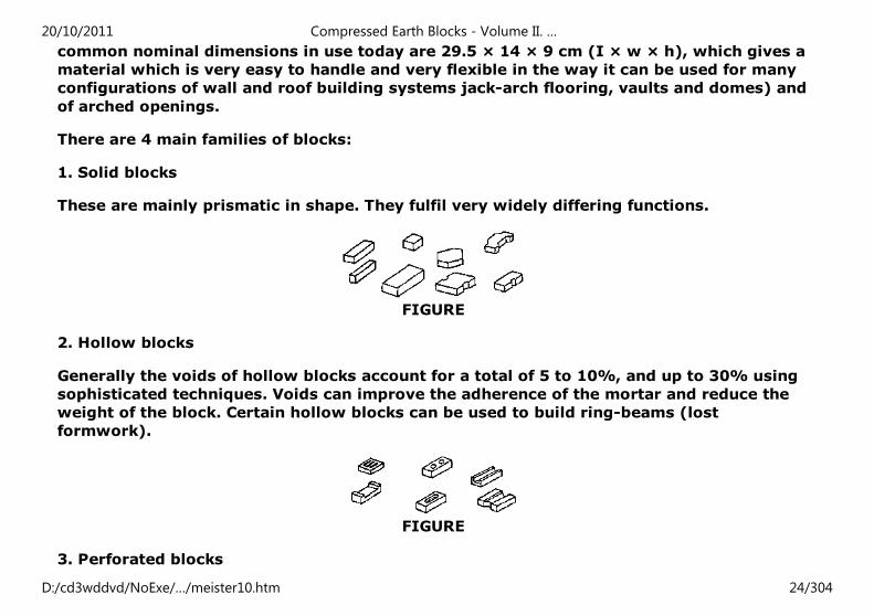
There are 4 main families of blocks:
1. Solid blocks
These are mainly prismatic in shape. They fulfil very widely differing functions.
FIGURE
2. Hollow blocks
Generally the voids of hollow blocks account for a total of 5 to 10%, and up to 30% using
sophisticated techniques. Voids can improve the adherence of the mortar and reduce the
weight of the block. Certain hollow blocks can be used to build ring-beams (lost
formwork).
FIGURE
3. Perforated blocks
20/10/2011 Compressed Earth Blocks - Volume II. …
D:/cd3wddvd/NoExe/…/meister10.htm 24/304
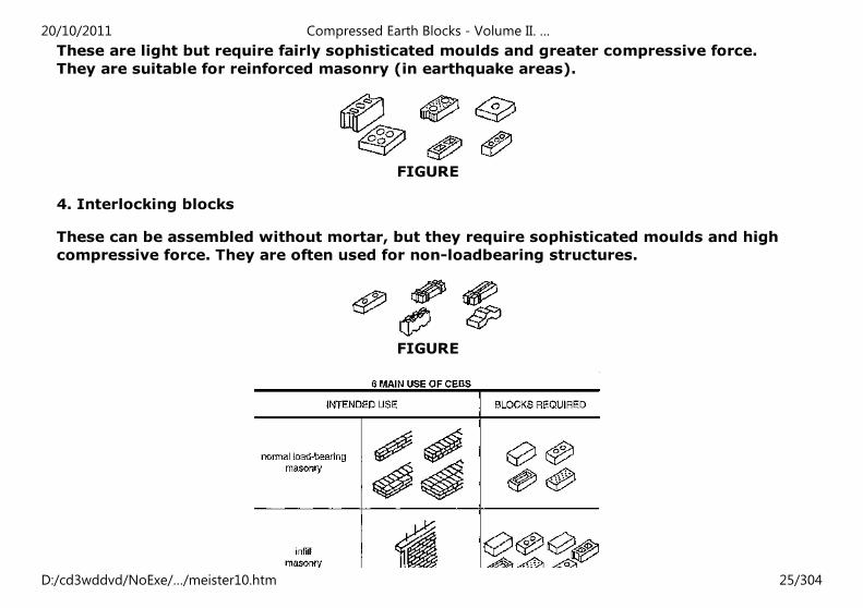
These are light but require fairly sophisticated moulds and greater compressive force.
They are suitable for reinforced masonry (in earthquake areas).
FIGURE
4. Interlocking blocks
These can be assembled without mortar, but they require sophisticated moulds and high
compressive force. They are often used for non-loadbearing structures.
FIGURE
20/10/2011 Compressed Earth Blocks - Volume II. …
D:/cd3wddvd/NoExe/…/meister10.htm 25/304
FIGURE
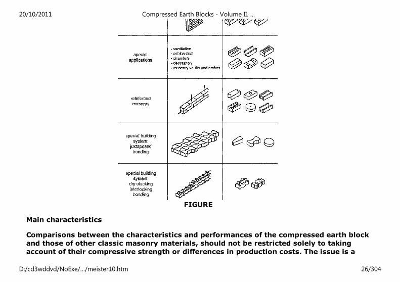
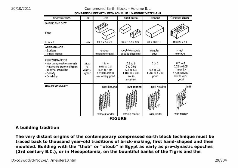
Main characteristics
Comparisons between the characteristics and performances of the compressed earth block
and those of other classic masonry materials, should not be restricted solely to taking
account of their compressive strength or differences in production costs. The issue is a
20/10/2011 Compressed Earth Blocks - Volume II. …
D:/cd3wddvd/NoExe/…/meister10.htm 26/304
more complex one and any comparison should rather be based on a wide register of
parameters, including: the shape and dimensions of the material, its appearance (surface,
texture, attractiveness,) as well as a full range of measures of performance, such as -
indeed - dry and wet compressive strength, but also thermal insulation, apparent density,
and durability. But over and above this, aspects linked to the production and use of the
material highlight all the complexity of such comparisons by taking account of such
factors as the nature of the soil deposits supplying the raw material, the means by which
this raw material is processed into a building material, the energy involved in this
processing, the nature of the material when considered as a building component or
element, and its state in the finished building, taking account of questions of durability
and maintenance. This «intelligent», way of comparing materials with each other, over
and above scientific considerations intended to compare materials in laboratory
conditions, takes account of the architectural and practical application of materials in situ.
ASPECTS OF UTILISATION
The position of the compressed earth block relative to other masonry materials can be
established according to aspects of use of the material.
Technical aspects
Its mechanical, static, hydrous, physical etc. characteristics.
Economic aspects
Unit production cost, capital investment, etc.
Health and safety aspects
The emission of dangerous fumes, radioactivity etc.
Psychological aspects
The nature of the material, surface texture, colour, shape, luminosity, etc.
20/10/2011 Compressed Earth Blocks - Volume II. …
D:/cd3wddvd/NoExe/…/meister10.htm 27/304
Ecological aspects
Deforestation, the hollowing out of hillsides as a result of quarrying, use of water and
energy sources, production of pollution and waste material etc.
Social aspects
Economic and social spin-offs resulting from job creation, socio-cultural acceptability, etc.
Institutional aspects
Legislation, insurance, norms, development policies linked to the setting up of productive
industries, etc.
Taking these various aspects into account leads directly back to the need to carry out a
preliminary technico-economic feasibility study before setting up a production system, for
these considerations weigh heavily in the choice of system. The table (Fig. 7) shows
simple points of comparison, but these should not overshadow the importance of these
various aspects of utilization of the material.
20/10/2011 Compressed Earth Blocks - Volume II. …
D:/cd3wddvd/NoExe/…/meister10.htm 28/304
FIGURE
A building tradition
The very distant origins of the contemporary compressed earth block technique must be
traced back to thousand year-old traditions of brick-making, first hand-shaped and then
moulded. Building with the "thob" or "otoub" in Egypt as early as pre-dynastic epoches
(3rd century B.C.), or in Mesopotamia, on the bountiful banks of the Tigris and the
20/10/2011 Compressed Earth Blocks - Volume II. …
D:/cd3wddvd/NoExe/…/meister10.htm 29/304
Euphrates, or again in the Indus valley, laid the foundations of "adobe" construction which
is still to be found in these regions and which has radiated out to many countries.
The use of the moulded earth brick remains linked to the fantastic evolution of mankind
which took place between the agricultural revolution of the neolithic age and the urban
revolution and corresponds to an advanced stage in the evolution of societies, and in the
organisation of materials production and the building of dwellings. With the building of
cities, the use of the earth brick was to be very quickly associated with architectural
prowess. Building using small masonry elements indeed liberated man from the most
rudimentary building technologies, such as waffle-and-daub or cob, which had restricted
building and architectural performance. The advent of the earth brick enabled the most
prestigious palaces, sanctuaries and religious temples of the great river civilizations (of
the Nile, the Tigris and Euphrates, the Indus and the Huanghe) to be erected, multiplying
the number of towns on fertile banks favourable to the installation of human settlements.
Modern and contemporary archeological studies bear witness to the architectural genius
of the builder of ancient times.
The progression from the moulded earth brick technique to the compacted earth block
corresponds to a logical improvement in the material. The increased density and reduced
porosity resulting from compression improve the behaviour of the earth block in the face
of the harmful effects of water. This compression technique was first practised manually
using a tamp and always inside moulds' a painstaking technique giving poor quality blocks
from the point of view of both appearance and mechanical performance. It was therefore
logical that the technique should gradually evolve towards the development of machinery.
The first presses emerged recently and were derived from the ceramic and calcium-silicate
industries; there then appeared a new generation of presses specific to compressed earth
block technology. This evolution from adobe, to compacted block and then to compressed
earth block remains a logical progression in many regions, although very often the
technological leap occurs directly between the adobe and the compressed earth block.
20/10/2011 Compressed Earth Blocks - Volume II. …
D:/cd3wddvd/NoExe/…/meister10.htm 30/304
The exposed wall's harmonious appearance
With the "modern movement" of the '20s end '30s, and then the "international style" of
the '70s end '80s, came an architectural language which used precise shapes, sharp edges,
and white facades made from industrialized building materials which demanded precise
and regular assembly. This form of architectural language clearly revealed the
predominance of the industrial machine over craftsmanship. With concrete, the modern
material par excellence, anything was possible, both good and bad, but its use did not
necessarily demand very high skills. In many cases, it must be admitted, the use of
concrete is not linked to very sophisticated skills. Some very attractive architectural uses
of concrete cannot disguise the overall mediocrity of contemporary architectural
structures. At the same time, this modern and international architectural style has never
really eclipsed the tradition of building using small exposed masonry elements which has
remained common throughout the industrialized countries of Latin or Anglo-saxon origin.
This latter architectural style is still perfectly contemporary and many architects are today
once again giving pride of place to the brick in their work. Those who come across the
compressed earth block generally find that it presents the same interest and flexibility in
use, and that it links back to a traditional architectural language.
Certain so-called "brick" countries (Great Britain, Belgium, Holland, etc.) have greatly
developed the art of the large exposed masonry wall. Very great architects have used brick
for their most beautiful works, both for housing and public buildings. The architectural
language of the brick, with its multitude of formal variations in expression, has always
been considered to be one of unparalleled flexibility and richness. In an inaugural speech
in 1938 in Chicago, Mies Van der Rohe declared: «Take a brick, how practical its small'
convenient size, so handy for any use. What logic in its bonding and in the resulting
texture. What richness in the most simple surface of a wall, and yet what a discipline this
material imposes». Who better than Louis Khan has given expression to the
seductiveness, the delight and harmony to be found in the contemporary architectural
20/10/2011 Compressed Earth Blocks - Volume II. …
D:/cd3wddvd/NoExe/…/meister10.htm 31/304
style of exposed bricks in which he finds a search for "romanity" and continuity? How
impossible to dissociate the harmony of the exposed wall from the delight and pleasure of
observing it. Present day compressed earth block architecture follows on in the succession
of brick architecture and is its direct descendant. It plays its part in the continuity of the
harmony of the exposed wall and the skills which unite architect and contractor. It is the
link woven with history.
Architecture for housing
Since the 1950s, which marked the emergence of the contemporary technology of
compressed earth block construction, the scope of activity in terms of architectural
realisations has continued to grow, both in industrialized and in developing countries. The
compressed earth block provides a complete response to demands for modernity linked to
the improvement of well-being and lifestyle in a comfortable, agreeable, and aesthetic
built environment, which is in harmony with the environment. It also meets economic
concerns, by enabling the most favourable socio-economic conditions of production, and,
notably in countries which are dependent on an outward-looking construction economy
based on the importation of materials, gives access to high quality housing at competitive
costs. When the technique has been fully mastered in the context of a production industry
which creates employment opportunities and skills, it gives rise to a "stock" of high
quality architecture which can then become a reference programme. Such is the case with
the compressed earth block architecture of the social housing and public facilities
programme which was implemented in the Comoro islands, on the island of Mayotte. In
France, the "romaine de la Terre" ("Earth Domain") project, which was completed in 1985
near Lyon, was a flagship operation for the renewal of earth architecture. The
demonstrative value of this operation, from a technological and architectural point of
view, opened the way for a renewal of earth architecture.
IN FRANCE, THE "DOMAINE DE LA TERRE"
20/10/2011 Compressed Earth Blocks - Volume II. …
D:/cd3wddvd/NoExe/…/meister10.htm 32/304
The "romaine de la Terre" project was the physical embodiment of the idea, which had
been advanced towards the end of the '70s, of once again using unbaked earth in the
organized building sector. By succeeding in mobilizing all the normal actors involved in
building production (planners and contractors, architects and entrepreneurs, technical
standards offices and insurance companies, research centres, production equipment and
building materials manufacturers), the project led the way for a new approach to building
with earth, based on actual implementation. It also resolved a number of problems to
which solutions had up till then not been found. Located in the Rhone-Alpes region, itself
rich in rammed earth architecture, it forms a link between vernacular traditions and
modernity. The "romaine de la Terre" operation, which provided local authority
accommodation at modest rents, consists of 65 housing units, grouped into 12 lots of 5 to
10 semi-detached or terraced units. The earth block was one of the earth building
techniques most used, with more then half of the buildings being built in vibration
compacted Barth blocks, the remainder being built from rammed earth (compacted
between shuttering) or taking the form of straw-clay (covering a wooden framework). The
architectural quality of the built estate and the demonstration of the economic feasibility
of this project, despite its experimental character, subsequently stimulated, both in France
and abroad, through the value as an exemplary operation, a significant development in the
realization of earth housing in general and using compressed earth blocks in particular.
Compressed earth block architecture for housing progressed significantly during the
1980s, both in European and in developing countries. Progress in scientific, technical and
architectural research on mastering the means of production of the material as well as its
application, the implementation of numerous pilot or experimental programmes, and the
dissemination of technical data amongst field operators, all contributed to the expansion
of a building market specific to this material. The building industry was right, if one is to
judge by the regular appearance on the market of new presses and other production
equipment (mixers, grinders, etc.). Simultaneously, the increasing importance attached to
training, at academic and at professional levels, and the development of sites linking
20/10/2011 Compressed Earth Blocks - Volume II. …
D:/cd3wddvd/NoExe/…/meister10.htm 33/304
production, construction and training, have helped to set up a network of skills favourable
to the blossoming of a genuine body of knowledge. Finally, mention must be made of the
support given by large international organizations, and notably the role played by UNIDO
(United Nations Industrial Development Organization), and CID (Centre for Industrial
Development) or UNCHS-Habitat (United Nations Centre for Human Settlements), linked to
a cooperation effort on the part of European countries (France, Germany) in the promotion
of this material and the support given to the setting up of compressed earth block
production industries, notably in African countries. The example of the social housing
programme in Mayotte (Comoro) remains most impressive: 6,000 low-cost houses and
nearly 1,000 public buildings (primary and secondary schools, state offices) have been
built in the space of 10 years on an island which in 1978 was still using wattle-and-daub
and raffia.
LOW-COST AND RENTED HOUSING
Marrakesh, Morocco
There has been renewed interest in building with compressed earth blocks since the
1980s. Between the traditional rammed earth and abobe of the "ksour" of southern
Morocco and the modern use of compressed earth blocks rendered with "taddelakt" (a
coloured and smoothed lime render), the architect Elie Mouyal is a fervent promoter of
this technique which he has exploited to build luxury homes framed by the greenery of
palm groves (figs. 16 and 18).
Mayotte, a Comores island
The compressed earth block industry was developed on Mayotte from 1980-81 onwards,
atthe initiative of the state public facilities department (Direction de l'Equipement) and
the Mayotte Housing Company (SIM). The SIM design team and the architects settled on
the island, desirous to make full use of local materials, very quickly become interested in
20/10/2011 Compressed Earth Blocks - Volume II. …
D:/cd3wddvd/NoExe/…/meister10.htm 34/304
this material, the technical qualities and architectural potential of which were to be very
soon demonstrated in the first housing and public facilities buildings. These first projects
were to pave the wayfor Mayotte's own architectural language, which was rapidly placed
at the service of a new-born genuine housing stock. The use of compressed earth blocks
was linked with other local materials (wood, raffia, basalt and phonolitic stone) as a real
building skill developed founded on a knowledge of the characteristics and potentialities
of these. Historic lever of development of a local architecture, the compressed earth block
has become a local material introducing new skills to Mayotte's small contractors and
craftsmen (figs. 19, 20 and 21).
Architecture for public buildings
Promoting the compressed earth block, from the perspective of setting up a local
production and construction industry, is an indispensable stage. Notably to overcome
psychological barriers, as the compressed earth block remains a construction material
which is linked in the minds not only of the people but also of professionals to the rustic
nature of traditional materials, as opposed to sand-cement blocks. In this initial phase, the
construction of public facilities buildings, as experience in a number of areas has shown, is
a major asset with great political and social impact.
On Mayotte, officials and locally-elected representatives, together with building
professionals, from the outset realized the importance of the demonstrative value of built
examples. The first pilot housing programmes were immediately linked to the construction
of primary schools in the vicinity of the largest built-up areas of the island and in rural
areas. Over an interval of ten years, all the administrative offices previously located
together at "Petite Terre", Pamandzi, were to be transferred to Mamoudzou, the
administrative capital of the island at "Grande Terre". The "Prefecture" (or main
administrative building), and the offices of the departments of health and social affairs, of
public facilities, and of education are of remarkable architectural quality and elegance and
20/10/2011 Compressed Earth Blocks - Volume II. …
D:/cd3wddvd/NoExe/…/meister10.htm 35/304
display their architects' intention to highlight the value of using the compressed earth
block combined with other local materials and with the skills acquired by the island's
craftsmen and contractors.
ADMINISTRATIVE BUILDINGS, SCHOOLS, HOTELS
Burkina Faso and Morocco
Many countries have adopted the approach of promoting the compressed earth block
through the construction of public facilities in the context of implementing local materials
construction strategies. In Burkina Faso and in Morocco, the compressed earth block has
been used for building schools, university accommodation, or luxury tourist hotels which
provide an opportunity to demonstrate/he quality of the material and the part it can play
in high quality architecture. Such projects are the spear-head of a new confidence and
interest in building with earth which is emerging in present-day architectural production
(figs. 25, 26 and 27).
Home"" """"> ar.cn.de.en.es.fr.id.it.ph.po.ru.sw
Compressed Earth Blocks - Volume II. Manual of design and
construction (GTZ, 1995, 148 p.)
Masonry principles
(introduction...)
Mortar
Bonding patterns
Coursing
20/10/2011 Compressed Earth Blocks - Volume II. …
D:/cd3wddvd/NoExe/…/meister10.htm 36/304
Compressed Earth Blocks - Volume II. Manual of design and construction (GTZ, 1995, 148
p.)
Masonry principles
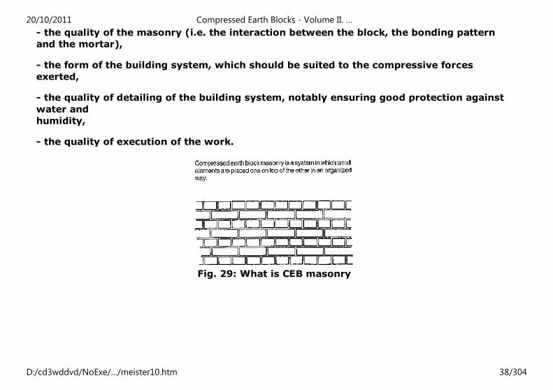
A compressed earth block masonry structure consists of small building elements placed
one on top of the other following a particular bonding pattern and bound together with
mortar.
The earth blocks therefore form a building system - whether it be a wall or a partition, a
post or a pillar, an arch, a vault or a dome - which has compressive strength. This
characteristic of compressive strength is indeed essential as, by contrast, masonry
structures using small elements have very little tensile strength.
The good strength and good stability of a masonry structure using small elements is
dependent on the interaction of several factors:
- the quality of the block itself,
20/10/2011 Compressed Earth Blocks - Volume II. …
D:/cd3wddvd/NoExe/…/meister10.htm 37/304
- the quality of the masonry (i.e. the interaction between the block, the bonding pattern
and the mortar),
- the form of the building system, which should be suited to the compressive forces
exerted,
- the quality of detailing of the building system, notably ensuring good protection against
water and
humidity,
- the quality of execution of the work.
Fig. 29: What is CEB masonry
20/10/2011 Compressed Earth Blocks - Volume II. …
D:/cd3wddvd/NoExe/…/meister10.htm 38/304
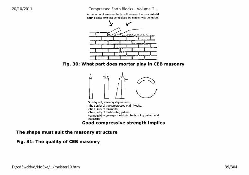
Fig. 30: What part does mortar play in CEB masonry
Good compressive strength implies
The shape must suit the masonry structure
Fig. 31: The quality of CEB masonry
20/10/2011 Compressed Earth Blocks - Volume II. …
D:/cd3wddvd/NoExe/…/meister10.htm 39/304
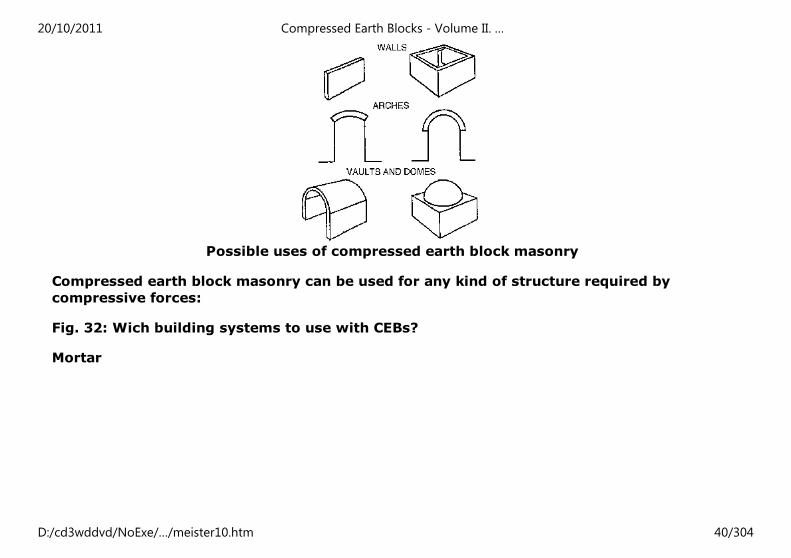
Possible uses of compressed earth block masonry
Compressed earth block masonry can be used for any kind of structure required by
compressive forces:
Fig. 32: Wich building systems to use with CEBs?
Mortar
20/10/2011 Compressed Earth Blocks - Volume II. …
D:/cd3wddvd/NoExe/…/meister10.htm 40/304
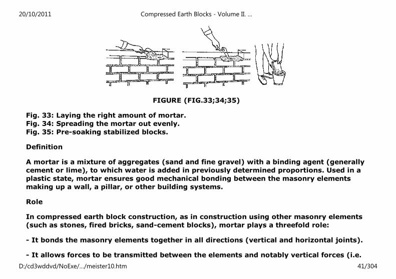
FIGURE (FIG.33;34;35)
Fig. 33: Laying the right amount of mortar.
Fig. 34: Spreading the mortar out evenly.
Fig. 35: Pre-soaking stabilized blocks.
Definition
A mortar is a mixture of aggregates (sand and fine gravel) with a binding agent (generally
cement or lime), to which water is added in previously determined proportions. Used in a
plastic state, mortar ensures good mechanical bonding between the masonry elements
making up a wall, a pillar, or other building systems.
Role
In compressed earth block construction, as in construction using other masonry elements
(such as stones, fired bricks, sand-cement blocks), mortar plays a threefold role:
- It bonds the masonry elements together in all directions (vertical and horizontal joints).
- It allows forces to be transmitted between the elements and notably vertical forces (i.e.
20/10/2011 Compressed Earth Blocks - Volume II. …
D:/cd3wddvd/NoExe/…/meister10.htm 41/304
the weight of the elements themselves, or applied forces).
- It enables these forces to be distributed across the whole surface of the masonry
elements.
- It compensates for any defects in horizontality in the execution of the masonry work.
Properties and characteristics
When freshly mixed, mortar should be easily "worked". Apart from having a suitable
consistency, it should display good cohesion, as well as the capacity to retain water
against the suction of the masonry elements on which it is applied.
Apart from its consistency, mortar used for compressed earth block construction should:
- Be able to change shape.
- Allow good permeability to humidity.
- Have mechanical performances which are compatible with that of the compressed earth
blocks.
Composition
The composition of the mortar should in each case take account of the actual requirements
of the masonry structure.
A good mortar should have good mechanical strength and should have the same
compressive strength and resistance to erosion as the compressed earth blocks.
Too low a strength mortar carries the risk of erosion, water infiltration and the
20/10/2011 Compressed Earth Blocks - Volume II. …
D:/cd3wddvd/NoExe/…/meister10.htm 42/304
deterioration of the compressed earth blocks. Erosion and cracking of the mortar, in
addition to tensile forces, results in a risk of rupture.
Too high a strength mortar carries the risk of water stagnating on parts of the visible
mortar matrix standing proud of the surface which in turn causes the erosion of the
blocks; this can result in the blocks cracking and in lowering their strength.
The texture of a good mortar is generally more sandy than that of compressed earth
blocks, with a maximum particle diameter of 2 to 5 mm. Stabilized mortar must always be
used with stabilized compressed earth blocks. In this event, the proportion of cement or
lime used should be increased by a factor of 1.5 or 2 to achieve the same strength as the
earth blocks.
It could be possible to use a non-stabilized earth mortar if one is sure that the walls which
are to be built with this mortar are well sheltered from exposure to rain or to water in
general. But even so, it will still be necessary to ensure that the non-stabilized mortar has
the same compressive strength and resistance to erosion as the earth blocks.
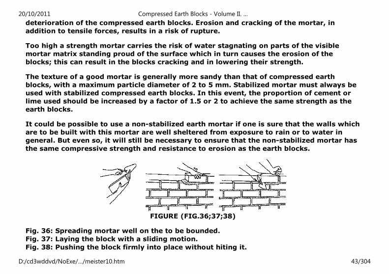
FIGURE (FIG.36;37;38)
Fig. 36: Spreading mortar well on the to be bounded.
Fig. 37: Laying the block with a sliding motion.
Fig. 38: Pushing the block firmly into place without hiting it.
20/10/2011 Compressed Earth Blocks - Volume II. …
D:/cd3wddvd/NoExe/…/meister10.htm 43/304
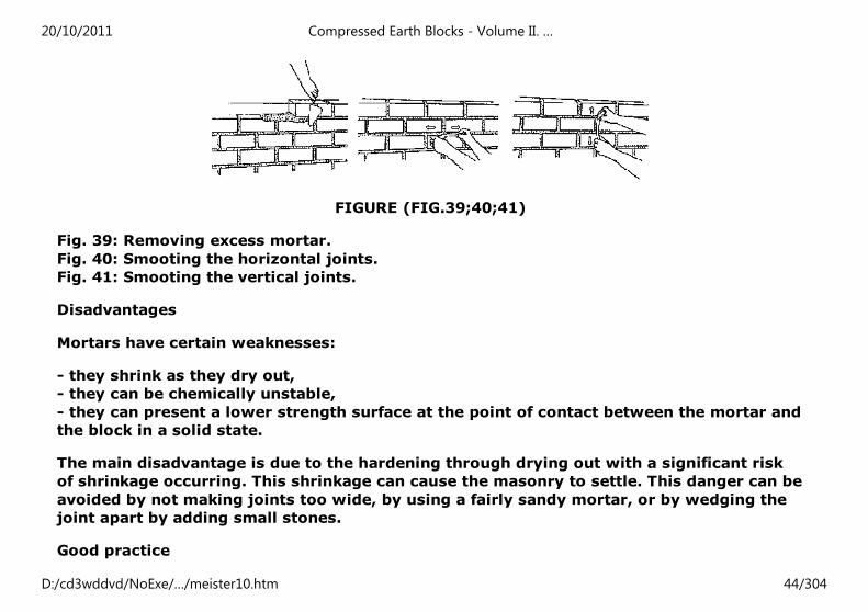
FIGURE (FIG.39;40;41)
Fig. 39: Removing excess mortar.
Fig. 40: Smooting the horizontal joints.
Fig. 41: Smooting the vertical joints.
Disadvantages
Mortars have certain weaknesses:
- they shrink as they dry out,
- they can be chemically unstable,
- they can present a lower strength surface at the point of contact between the mortar and
the block in a solid state.
The main disadvantage is due to the hardening through drying out with a significant risk
of shrinkage occurring. This shrinkage can cause the masonry to settle. This danger can be
avoided by not making joints too wide, by using a fairly sandy mortar, or by wedging the
joint apart by adding small stones.
Good practice
20/10/2011 Compressed Earth Blocks - Volume II. …
D:/cd3wddvd/NoExe/…/meister10.htm 44/304
The mixing water of the mortar should be clean (i.e. clear and non-acidic). The surface to
which it is to be applied should be prepared and clean.
The bonding of the blocks should be correct in both directions of the bonding pattern,
using vertical and horizontal joints. Vertical joints should be well filled. Care should be
taken to prevent the mortar drying out too quickly (e.g. sprinkling the wall in hot
countries) and in general to avoid dramatic changes in temperature (special care must be
taken in regions where the diurnal temperature range is particularly great.)
The width of the mortar joints, both horizontal and vertical, should be even and a
maximum of 1 to 1.5 cm.
For stabilized compressed earth blocks, blocks should be pre-soaked, and the surface on
which they are to be placed should also be moistened. The block should be "spread" with
the right quantities of mortar on the sides to be bonded.
Once the block has been laid, it should be pushed firmly into place, but above all it should
never be tapped or hit as this could destroy the adherence between the block and the
mortar.
The joints should be smoothed as soon as the blocks have been laid, either using a jointer,
or a piece of wet plastic tubing, wood or bamboo.
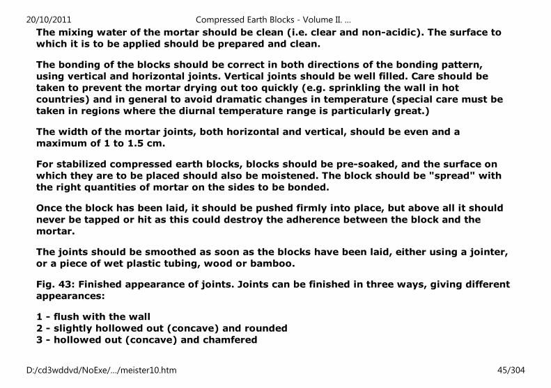
Fig. 43: Finished appearance of joints. Joints can be finished in three ways, giving different
appearances:
1 - flush with the wall
2 - slightly hollowed out (concave) and rounded
3 - hollowed out (concave) and chamfered
20/10/2011 Compressed Earth Blocks - Volume II. …
D:/cd3wddvd/NoExe/…/meister10.htm 45/304
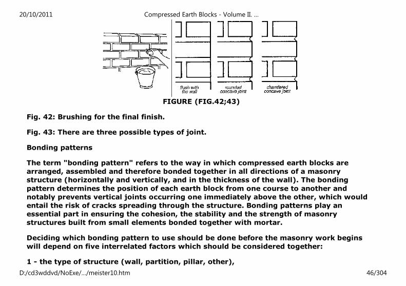
FIGURE (FIG.42;43)
Fig. 42: Brushing for the final finish.
Fig. 43: There are three possible types of joint.
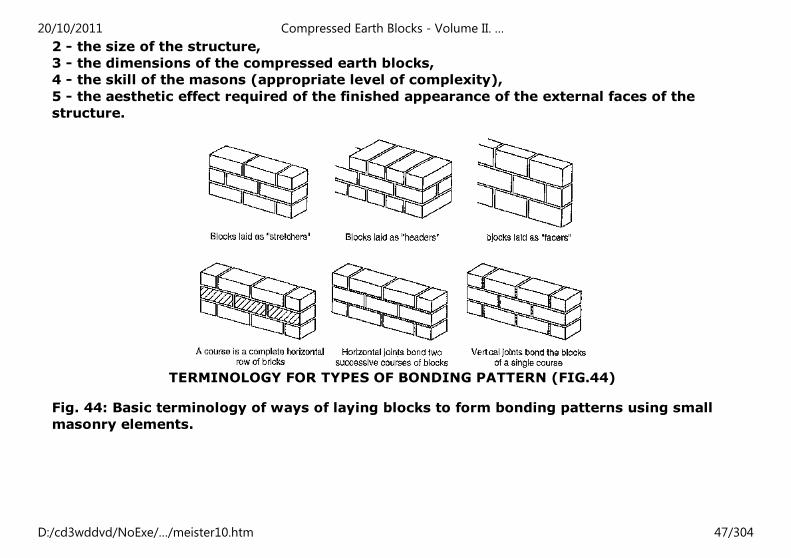
Bonding patterns
The term "bonding pattern" refers to the way in which compressed earth blocks are
arranged, assembled and therefore bonded together in all directions of a masonry
structure (horizontally and vertically, and in the thickness of the wall). The bonding
pattern determines the position of each earth block from one course to another and
notably prevents vertical joints occurring one immediately above the other, which would
entail the risk of cracks spreading through the structure. Bonding patterns play an
essential part in ensuring the cohesion, the stability and the strength of masonry
structures built from small elements bonded together with mortar.
Deciding which bonding pattern to use should be done before the masonry work begins
will depend on five interrelated factors which should be considered together:
1 - the type of structure (wall, partition, pillar, other),
20/10/2011 Compressed Earth Blocks - Volume II. …
D:/cd3wddvd/NoExe/…/meister10.htm 46/304
2 - the size of the structure,
3 - the dimensions of the compressed earth blocks,
4 - the skill of the masons (appropriate level of complexity),
5 - the aesthetic effect required of the finished appearance of the external faces of the
structure.
TERMINOLOGY FOR TYPES OF BONDING PATTERN (FIG.44)
Fig. 44: Basic terminology of ways of laying blocks to form bonding patterns using small
masonry elements.
20/10/2011 Compressed Earth Blocks - Volume II. …
D:/cd3wddvd/NoExe/…/meister10.htm 47/304
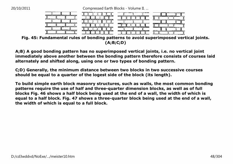
Fig. 45: Fundamental rules of bonding patterns to avoid superimposed vertical joints.
(A;B;C;D)
A;B) A good bonding pattern has no superimposed vertical joints, i.e. no vertical joint
immediately above another between the bonding pattern therefore consists of courses laid
alternately and shifted along, using one or two types of bonding pattern.
C;D) Generally, the minimum distance between two blocks in two successive courses
should be equal to a quarter of the logest side of the block (its length).
To build simple earth block masonry structures, such as walls, the most common bonding
patterns require the use of half and three-quarter dimension blocks, as well as of full
blocks Fig. 46 shows a half block being used at the end of a wall, the width of which is
equal to a half block. Fig. 47 shows a three-quarter block being used at the end of a wall,
the width of which is equal to a full block.
20/10/2011 Compressed Earth Blocks - Volume II. …
D:/cd3wddvd/NoExe/…/meister10.htm 48/304
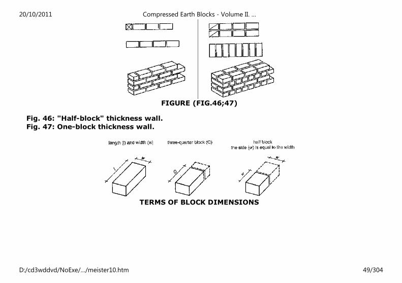
FIGURE (FIG.46;47)
Fig. 46: "Half-block" thickness wall.
Fig. 47: One-block thickness wall.
TERMS OF BLOCK DIMENSIONS
20/10/2011 Compressed Earth Blocks - Volume II. …
D:/cd3wddvd/NoExe/…/meister10.htm 49/304
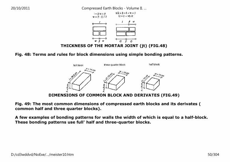
THICKNESS OF THE MORTAR JOINT (jt) (FIG.48)
Fig. 48: Terms and rules for block dimensions using simple bonding patterns.
DIMENSIONS OF COMMON BLOCK AND DERIVATES (FIG.49)
Fig. 49: The most common dimensions of compressed earth blocks and its derivates (
common half and three quarter blocks).
A few examples of bonding patterns for walls the width of which is equal to a half-block.
These bonding patterns use full' half and three-quarter blocks.
20/10/2011 Compressed Earth Blocks - Volume II. …
D:/cd3wddvd/NoExe/…/meister10.htm 50/304
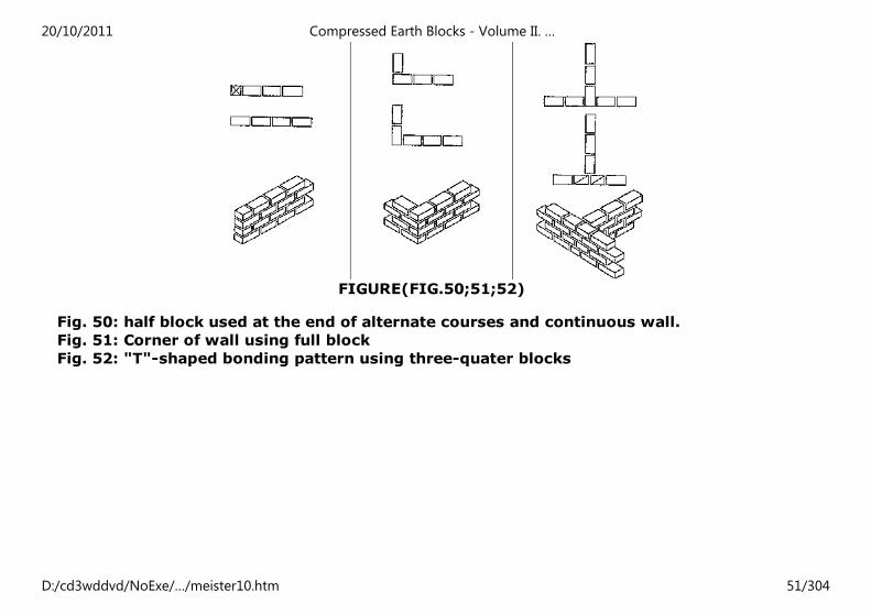
FIGURE(FIG.50;51;52)
Fig. 50: half block used at the end of alternate courses and continuous wall.
Fig. 51: Corner of wall using full block
Fig. 52: "T"-shaped bonding pattern using three-quater blocks
20/10/2011 Compressed Earth Blocks - Volume II. …
D:/cd3wddvd/NoExe/…/meister10.htm 51/304
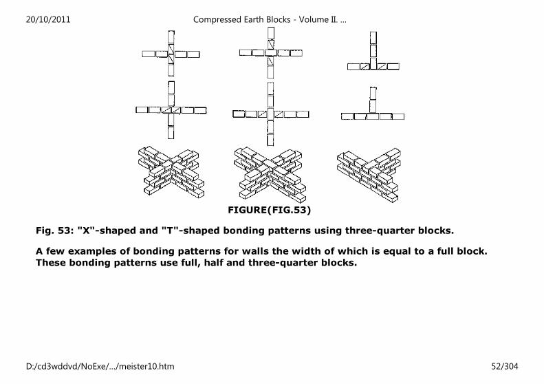
FIGURE(FIG.53)
Fig. 53: "X"-shaped and "T"-shaped bonding patterns using three-quarter blocks.
A few examples of bonding patterns for walls the width of which is equal to a full block.
These bonding patterns use full, half and three-quarter blocks.
20/10/2011 Compressed Earth Blocks - Volume II. …
D:/cd3wddvd/NoExe/…/meister10.htm 52/304
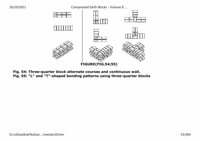
FIGURE(FIG.54;55)
Fig. 54: Three-quarter block alternate courses and continuous wall.
Fig. 55: "L" and "T"-shaped bonding patterns using three-quarter blocks
20/10/2011 Compressed Earth Blocks - Volume II. …
D:/cd3wddvd/NoExe/…/meister10.htm 53/304
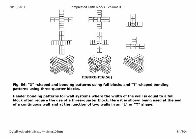
FIGURE(FIG.56)
Fig. 56: "X" -shaped and bonding patterns using full blocks and "T"-shaped bonding
patterns using three-quarter blocks.
Header bonding patterns for wall systems where the width of the wall is equal to a full
block often require the use of a three-quarter block. Here it is shown being used at the end
of a continuous wall and at the junction of two walls in an "L" or "T" shape.
20/10/2011 Compressed Earth Blocks - Volume II. …
D:/cd3wddvd/NoExe/…/meister10.htm 54/304
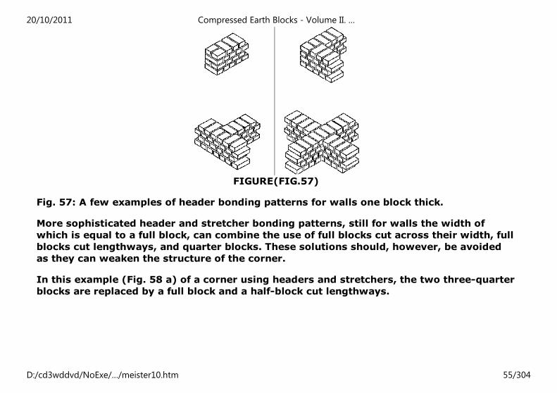
FIGURE(FIG.57)
Fig. 57: A few examples of header bonding patterns for walls one block thick.
More sophisticated header and stretcher bonding patterns, still for walls the width of
which is equal to a full block, can combine the use of full blocks cut across their width, full
blocks cut lengthways, and quarter blocks. These solutions should, however, be avoided
as they can weaken the structure of the corner.
In this example (Fig. 58 a) of a corner using headers and stretchers, the two three-quarter
blocks are replaced by a full block and a half-block cut lengthways.
20/10/2011 Compressed Earth Blocks - Volume II. …
D:/cd3wddvd/NoExe/…/meister10.htm 55/304
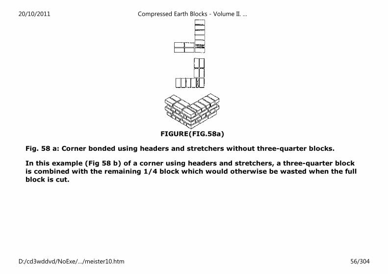
FIGURE(FIG.58a)
Fig. 58 a: Corner bonded using headers and stretchers without three-quarter blocks.
In this example (Fig 58 b) of a corner using headers and stretchers, a three-quarter block
is combined with the remaining 1/4 block which would otherwise be wasted when the full
block is cut.
20/10/2011 Compressed Earth Blocks - Volume II. …
D:/cd3wddvd/NoExe/…/meister10.htm 56/304
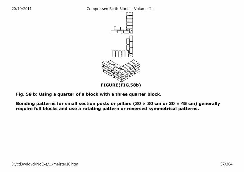
FIGURE(FIG.58b)
Fig. 58 b: Using a quarter of a block with a three quarter block.
Bonding patterns for small section posts or pillars (30 × 30 cm or 30 × 45 cm) generally
require full blocks and use a rotating pattern or reversed symmetrical patterns.
20/10/2011 Compressed Earth Blocks - Volume II. …
D:/cd3wddvd/NoExe/…/meister10.htm 57/304
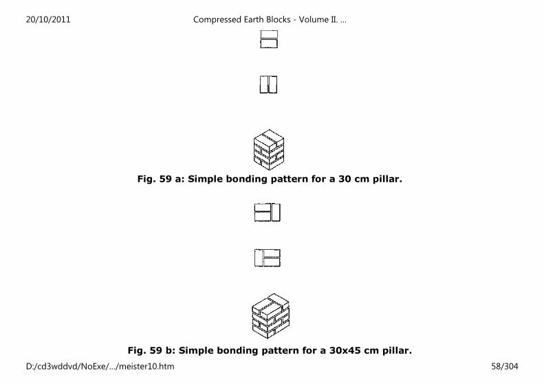
Fig. 59 a: Simple bonding pattern for a 30 cm pillar.
Fig. 59 b: Simple bonding pattern for a 30x45 cm pillar.
20/10/2011 Compressed Earth Blocks - Volume II. …
D:/cd3wddvd/NoExe/…/meister10.htm 58/304
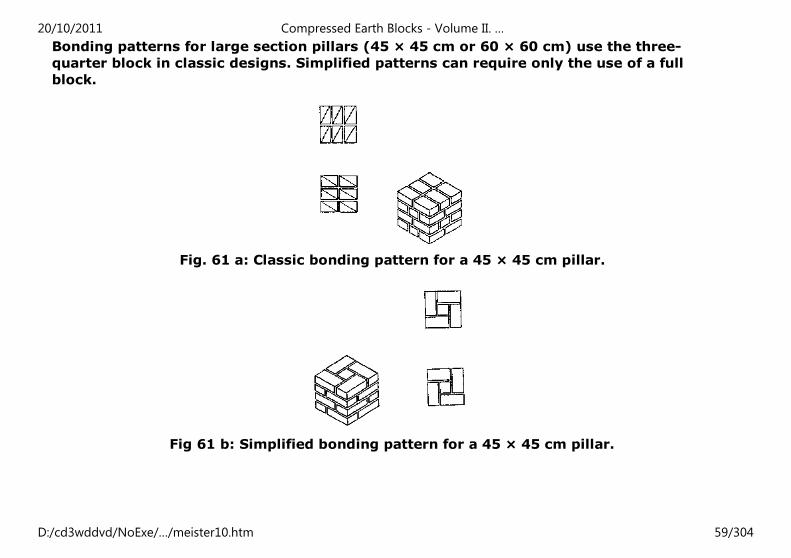
Bonding patterns for large section pillars (45 × 45 cm or 60 × 60 cm) use the three-
quarter block in classic designs. Simplified patterns can require only the use of a full
block.
Fig. 61 a: Classic bonding pattern for a 45 × 45 cm pillar.
Fig 61 b: Simplified bonding pattern for a 45 × 45 cm pillar.
20/10/2011 Compressed Earth Blocks - Volume II. …
D:/cd3wddvd/NoExe/…/meister10.htm 59/304
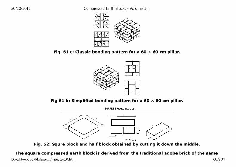
Fig. 61 c: Classic bonding pattern for a 60 × 60 cm pillar.
Fig 61 b: Simplified bonding pattern for a 60 × 60 cm pillar.
Fig. 62: Squre block and half block obtained by cutting it down the middle.
The square compressed earth block is derived from the traditional adobe brick of the same
20/10/2011 Compressed Earth Blocks - Volume II. …
D:/cd3wddvd/NoExe/…/meister10.htm 60/304
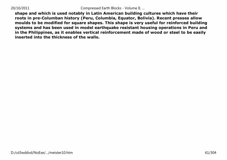
shape and which is used notably in Latin American building cultures which have their
roots in pre-Columban history (Peru, Columbia, Equator, Bolivia). Recent presses allow
moulds to be modified for square shapes. This shape is very useful for reinforced building
systems and has been used in model earthquake resistant housing operations in Peru and
in the Philippines, as it enables vertical reinforcement made of wood or steel to be easily
inserted into the thickness of the walls.
20/10/2011 Compressed Earth Blocks - Volume II. …
D:/cd3wddvd/NoExe/…/meister10.htm 61/304
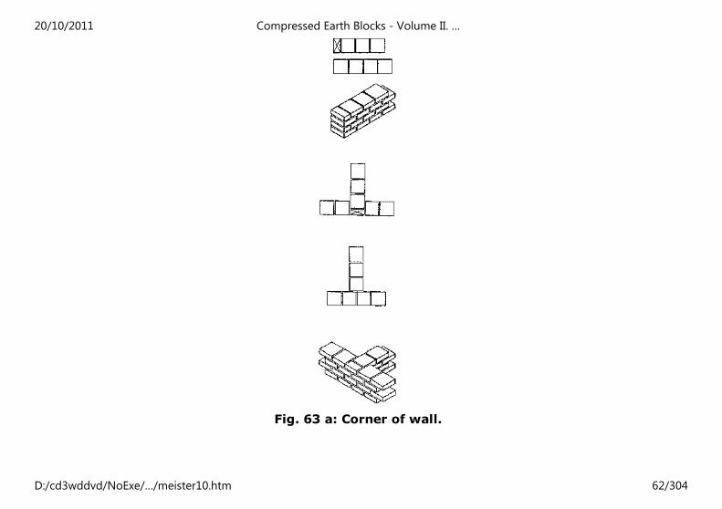
Fig. 63 a: Corner of wall.
20/10/2011 Compressed Earth Blocks - Volume II. …
D:/cd3wddvd/NoExe/…/meister10.htm 62/304
20/10/2011 Compressed Earth Blocks - Volume II. …
D:/cd3wddvd/NoExe/…/meister10.htm 63/304
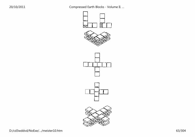
Fig. 63 b: Walls crosing in "X" configuration.
Coursing
Building using small masonry elements has the advantage of great flexibility in use
resulting from a complete mastery of the modular use of the material. This modulation
combined with the dimensioning of building systems can be determined as a function of
the size of the building element, i.e. of the compressed earth block. It can also be
determined as a function of the principles of the block bonding patterns which are used in
the development of building systems.
"Coursing" is the link which the designer establishes between the dimensions of the
compressed earth block, the dimensioning of the building systems, and their architectural
representation in plan, elevation, section or detail. Coursing a compressed earth block
architectural plan is indispensable when preparing working drawings. It ensures good
project control in several ways:
- Coursing enables one to establish exact dimensions for the working drawings, in plan
and elevation, and thus to obtain precise quantitative data for the project. A well coursed
set of working drawings will be put to good use at the later stage of producing the
compressed earth blocks for the execution of the work on site, by specifying the exact
number of blocks required. It will also enable losses resulting from too much waste during
cutting to be monitored by specifying how many full, 3/4 and 1/4 blocks are required. - By
enabling the implementation of the works and the quality of the building systems used to
be controlled, coursing enables one to determine the exact dimensions of bays in the walls
(door and wall openings), the position of a ring-beam, the location of floor beams in a wall
etc. All this precision will be apparent in the quality of the finished structure.
- It contributes to the appearance of the project, by highlighting the attractiveness of the
material in the masonry of a visible compressed earth block wall. Precise modulation,
20/10/2011 Compressed Earth Blocks - Volume II. …
D:/cd3wddvd/NoExe/…/meister10.htm 64/304
thanks to coursing, underlies the aesthetic effect of all masonry using small elements
which results from the appearance of rythmic sequences in the visible wall.
COURSING, BONDING PATTERNS, MODULATION AND DIMENSIONING
20/10/2011 Compressed Earth Blocks - Volume II. …
D:/cd3wddvd/NoExe/…/meister10.htm 65/304
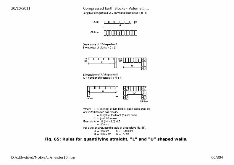
Fig. 65: Rules for quantifying straight, "L" and "U" shaped walls.
20/10/2011 Compressed Earth Blocks - Volume II. …
D:/cd3wddvd/NoExe/…/meister10.htm 66/304
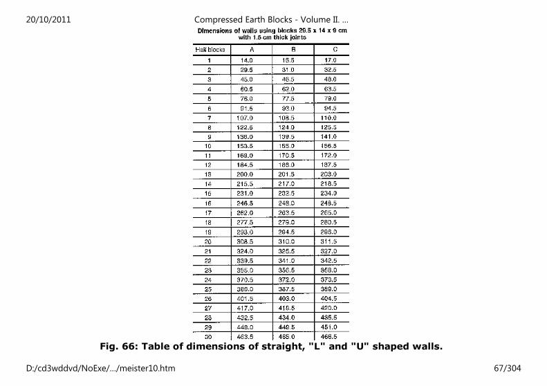
Fig. 66: Table of dimensions of straight, "L" and "U" shaped walls.
20/10/2011 Compressed Earth Blocks - Volume II. …
D:/cd3wddvd/NoExe/…/meister10.htm 67/304
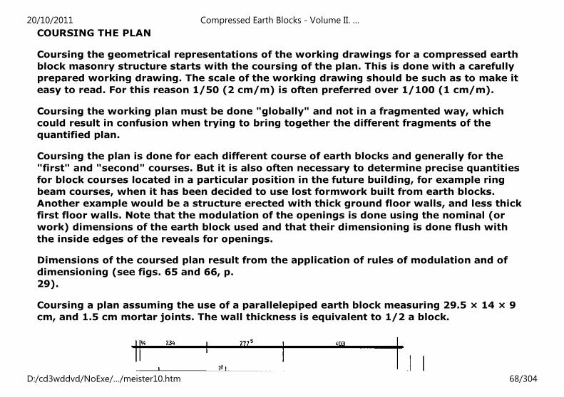
COURSING THE PLAN
Coursing the geometrical representations of the working drawings for a compressed earth
block masonry structure starts with the coursing of the plan. This is done with a carefully
prepared working drawing. The scale of the working drawing should be such as to make it
easy to read. For this reason 1/50 (2 cm/m) is often preferred over 1/100 (1 cm/m).
Coursing the working plan must be done "globally" and not in a fragmented way, which
could result in confusion when trying to bring together the different fragments of the
quantified plan.
Coursing the plan is done for each different course of earth blocks and generally for the
"first" and "second" courses. But it is also often necessary to determine precise quantities
for block courses located in a particular position in the future building, for example ring
beam courses, when it has been decided to use lost formwork built from earth blocks.
Another example would be a structure erected with thick ground floor walls, and less thick
first floor walls. Note that the modulation of the openings is done using the nominal (or
work) dimensions of the earth block used and that their dimensioning is done flush with
the inside edges of the reveals for openings.
Dimensions of the coursed plan result from the application of rules of modulation and of
dimensioning (see figs. 65 and 66, p.
29).
Coursing a plan assuming the use of a parallelepiped earth block measuring 29.5 × 14 × 9
cm, and 1.5 cm mortar joints. The wall thickness is equivalent to 1/2 a block.
20/10/2011 Compressed Earth Blocks - Volume II. …
D:/cd3wddvd/NoExe/…/meister10.htm 68/304
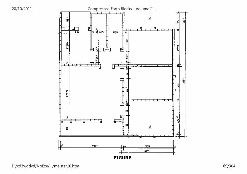
FIGURE
20/10/2011 Compressed Earth Blocks - Volume II. …
D:/cd3wddvd/NoExe/…/meister10.htm 69/304
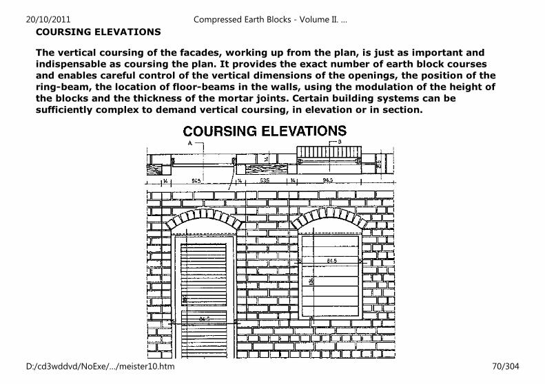
COURSING ELEVATIONS
The vertical coursing of the facades, working up from the plan, is just as important and
indispensable as coursing the plan. It provides the exact number of earth block courses
and enables careful control of the vertical dimensions of the openings, the position of the
ring-beam, the location of floor-beams in the walls, using the modulation of the height of
the blocks and the thickness of the mortar joints. Certain building systems can be
sufficiently complex to demand vertical coursing, in elevation or in section.
20/10/2011 Compressed Earth Blocks - Volume II. …
D:/cd3wddvd/NoExe/…/meister10.htm 70/304
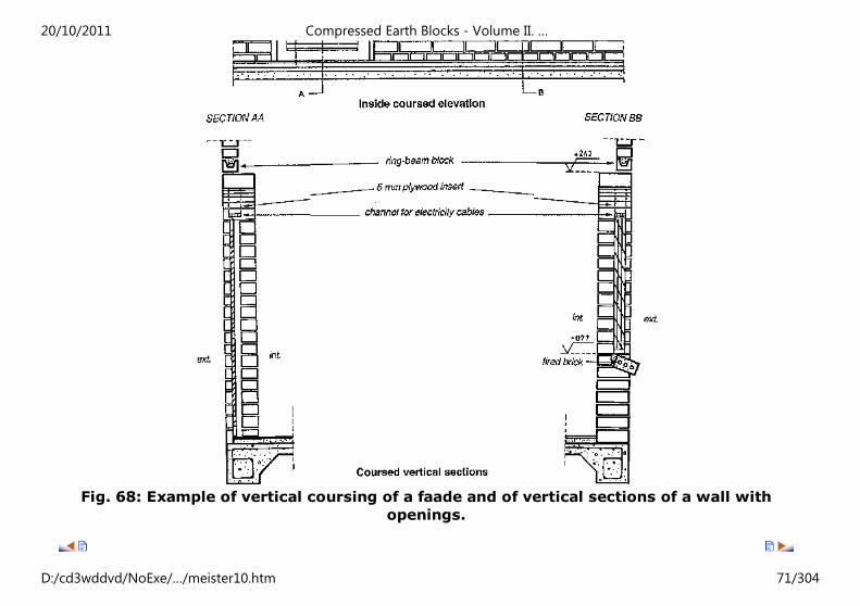
Fig. 68: Example of vertical coursing of a faade and of vertical sections of a wall with
openings.
20/10/2011 Compressed Earth Blocks - Volume II. …
D:/cd3wddvd/NoExe/…/meister10.htm 71/304
Home"" """"> ar.cn.de.en.es.fr.id.it.ph.po.ru.sw
Compressed Earth Blocks - Volume II. Manual of design and
construction (GTZ, 1995, 148 p.)
The project's building dispositions
(introduction...)
Types of wall
Types of structure
Foundations and footings
Openings
Reinforcement
Floors: structures
Jack arches and vaulting
Roof classification
Finishings
Installing technical systems
Characteristic strength of CEBS
Safety and height to width coefficients
Permissible constraints
Building economics
Compressed Earth Blocks - Volume II. Manual of design and construction (GTZ, 1995, 148
p.)
The project's building dispositions
20/10/2011 Compressed Earth Blocks - Volume II. …
D:/cd3wddvd/NoExe/…/meister10.htm 72/304
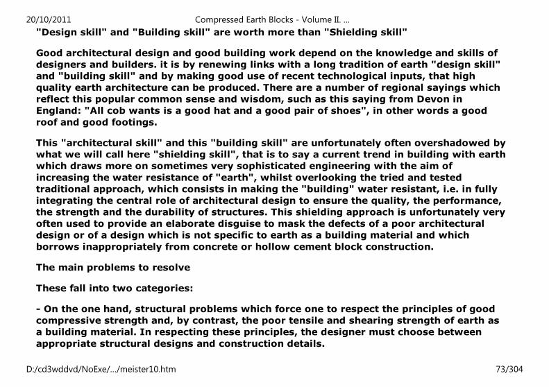
"Design skill" and "Building skill" are worth more than "Shielding skill"
Good architectural design and good building work depend on the knowledge and skills of
designers and builders. it is by renewing links with a long tradition of earth "design skill"
and "building skill" and by making good use of recent technological inputs, that high
quality earth architecture can be produced. There are a number of regional sayings which
reflect this popular common sense and wisdom, such as this saying from Devon in
England: "All cob wants is a good hat and a good pair of shoes", in other words a good
roof and good footings.
This "architectural skill" and this "building skill" are unfortunately often overshadowed by
what we will call here "shielding skill", that is to say a current trend in building with earth
which draws more on sometimes very sophisticated engineering with the aim of
increasing the water resistance of "earth", whilst overlooking the tried and tested
traditional approach, which consists in making the "building" water resistant, i.e. in fully
integrating the central role of architectural design to ensure the quality, the performance,
the strength and the durability of structures. This shielding approach is unfortunately very
often used to provide an elaborate disguise to mask the defects of a poor architectural
design or of a design which is not specific to earth as a building material and which
borrows inappropriately from concrete or hollow cement block construction.
The main problems to resolve
These fall into two categories:
- On the one hand, structural problems which force one to respect the principles of good
compressive strength and, by contrast, the poor tensile and shearing strength of earth as
a building material. In respecting these principles, the designer must choose between
appropriate structural designs and construction details.
20/10/2011 Compressed Earth Blocks - Volume II. …
D:/cd3wddvd/NoExe/…/meister10.htm 73/304
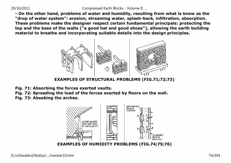
- On the other hand, problems of water and humidity, resulting from what is know as the
"drop of water system": erosion, streaming water, splash-back, infiltration, absorption.
These problems make the designer respect certain fundamental principals: protecting the
top and the base of the walls ("a good hat and good shoes"), allowing the earth building
material to breathe and incorporating suitable details into the design principles.
EXAMPLES OF STRUCTURAL PROBLEMS (FIG.71;72;73)
Fig. 71: Absorbing the forces exerted vaults.
Fig. 72: Spreading the load of the forces exerted by floors on the wall.
Fig. 73: Absobing the arches.
EXAMPLES OF HUMIDITY PROBLEMS (FIG.74;75;76)
20/10/2011 Compressed Earth Blocks - Volume II. …
D:/cd3wddvd/NoExe/…/meister10.htm 74/304
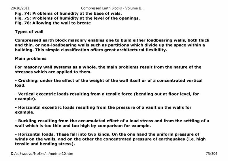
Fig. 74: Problems of humidity at the base of wals.
Fig. 75: Problems of humidity at the level of the openings.
Fig. 76: Allowing the wall to breate
Types of wall
Compressed earth block masonry enables one to build either loadbearing walls, both thick
and thin, or non-loadbearing walls such as partitions which divide up the space within a
building. This simple classification offers great architectural flexibility.
Main problems
For masonry wall systems as a whole, the main problems result from the nature of the
stresses which are applied to them.
- Crushing: under the effect of the weight of the wall itself or of a concentrated vertical
load.
- Vertical excentric loads resulting from a tensile force (bending out at floor level, for
example).
- Horizontal excentric loads resulting from the pressure of a vault on the walls for
example.
- Buckling resulting from the accumulated effect of a load stress and from the settling of a
wall which is too thin and too high by comparison for example.
- Horizontal loads. These fall into two kinds. On the one hand the uniform pressure of
winds on the walls, and on the other the concentrated pressure of earthquakes (i.e. high
tensile and bending stress).
20/10/2011 Compressed Earth Blocks - Volume II. …
D:/cd3wddvd/NoExe/…/meister10.htm 75/304
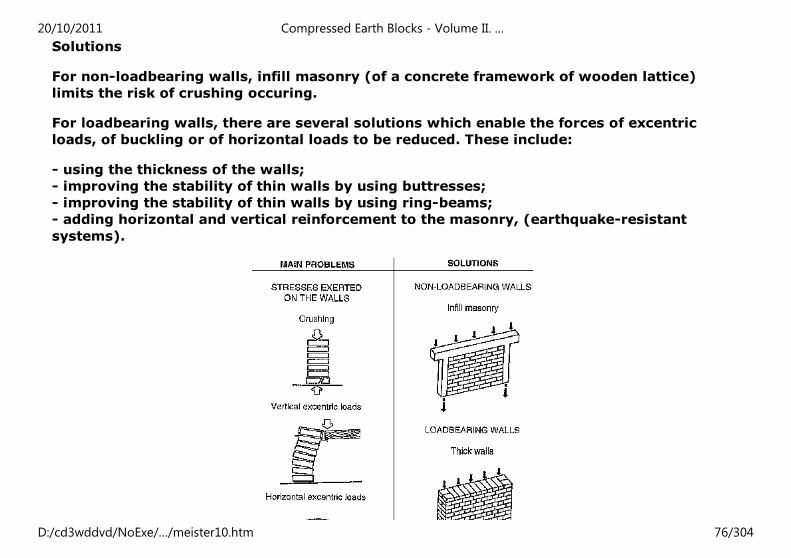
Solutions
For non-loadbearing walls, infill masonry (of a concrete framework of wooden lattice)
limits the risk of crushing occuring.
For loadbearing walls, there are several solutions which enable the forces of excentric
loads, of buckling or of horizontal loads to be reduced. These include:
- using the thickness of the walls;
- improving the stability of thin walls by using buttresses;
- improving the stability of thin walls by using ring-beams;
- adding horizontal and vertical reinforcement to the masonry, (earthquake-resistant
systems).
20/10/2011 Compressed Earth Blocks - Volume II. …
D:/cd3wddvd/NoExe/…/meister10.htm 76/304
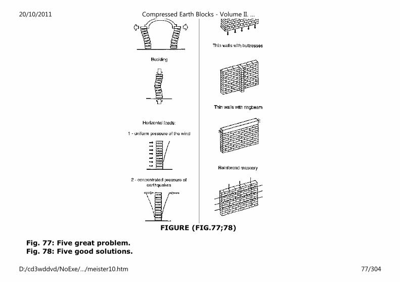
FIGURE (FIG.77;78)
Fig. 77: Five great problem.
Fig. 78: Five good solutions.
20/10/2011 Compressed Earth Blocks - Volume II. …
D:/cd3wddvd/NoExe/…/meister10.htm 77/304
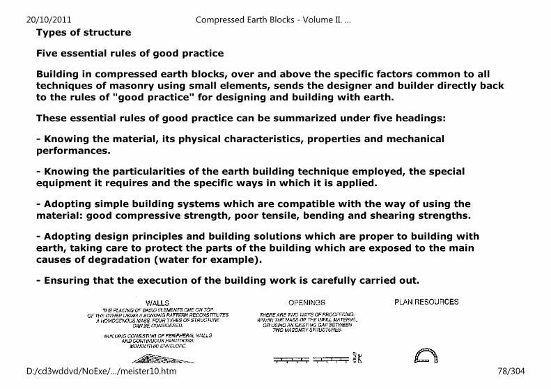
Types of structure
Five essential rules of good practice
Building in compressed earth blocks, over and above the specific factors common to all
techniques of masonry using small elements, sends the designer and builder directly back
to the rules of "good practice" for designing and building with earth.
These essential rules of good practice can be summarized under five headings:
- Knowing the material, its physical characteristics, properties and mechanical
performances.
- Knowing the particularities of the earth building technique employed, the special
equipment it requires and the specific ways in which it is applied.
- Adopting simple building systems which are compatible with the way of using the
material: good compressive strength, poor tensile, bending and shearing strengths.
- Adopting design principles and building solutions which are proper to building with
earth, taking care to protect the parts of the building which are exposed to the main
causes of degradation (water for example).
- Ensuring that the execution of the building work is carefully carried out.
20/10/2011 Compressed Earth Blocks - Volume II. …
D:/cd3wddvd/NoExe/…/meister10.htm 78/304
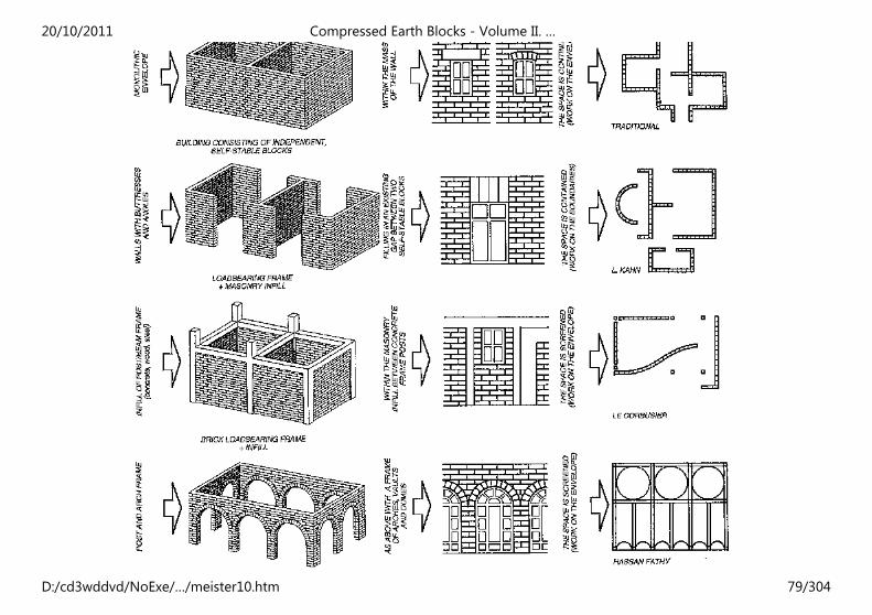
20/10/2011 Compressed Earth Blocks - Volume II. …
D:/cd3wddvd/NoExe/…/meister10.htm 79/304
Fig. 79: Table showing the links between structural principles, types of wall and openings
and the architectural resources of the plan.
Foundations and footings
Two types of problem
Particular care should be taken with the foundations and footings of a compressed earth
block building and the building should be protected from two main types of problem:
- structural problems,
- problems linked to humidity.
This is because buildings constructed from compressed earth blocks, by the very nature of
the material, are vulnerable to inherent structural risks or to humidity which can cause
very serious damage. One must therefore be particularly vigilant in respecting the rules
and codes of good practice which are specific to building with earth. This does not mean,
however, that problems stem only from the nature of the material; they can arise because
of external factors - differential settling, landslides, and natural disasters such as
earthquakes and floods - which will be even more damaging if the building has been badly
designed or built.
Choosing a system of foundations and footings
This will depend on the nature of the ground on which the structure is to be built and the
type of structure envisaged. There is a danger of structural weakness when building on
unstable or weak sites. This danger can be increased by a poor design
(underdimensionning or insufficient strength for example) or if the foundations are badly
built (located excentrically to the downward loads for example). On poorly-drained sites,
humidity can increase the risk of structural weakness as this can considerably weaken the
20/10/2011 Compressed Earth Blocks - Volume II. …
D:/cd3wddvd/NoExe/…/meister10.htm 80/304
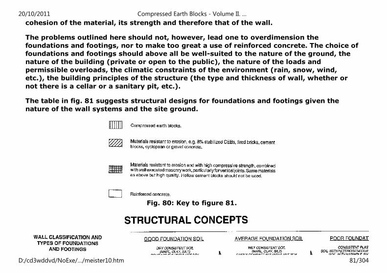
cohesion of the material, its strength and therefore that of the wall.
The problems outlined here should not, however, lead one to overdimension the
foundations and footings, nor to make too great a use of reinforced concrete. The choice of
foundations and footings should above all be well-suited to the nature of the ground, the
nature of the building (private or open to the public), the nature of the loads and
permissible overloads, the climatic constraints of the environment (rain, snow, wind,
etc.), the building principles of the structure (the type and thickness of wall, whether or
not there is a cellar or a sanitary pit, etc.).
The table in fig. 81 suggests structural designs for foundations and footings given the
nature of the wall systems and the site ground.
Fig. 80: Key to figure 81.
20/10/2011 Compressed Earth Blocks - Volume II. …
D:/cd3wddvd/NoExe/…/meister10.htm 81/304
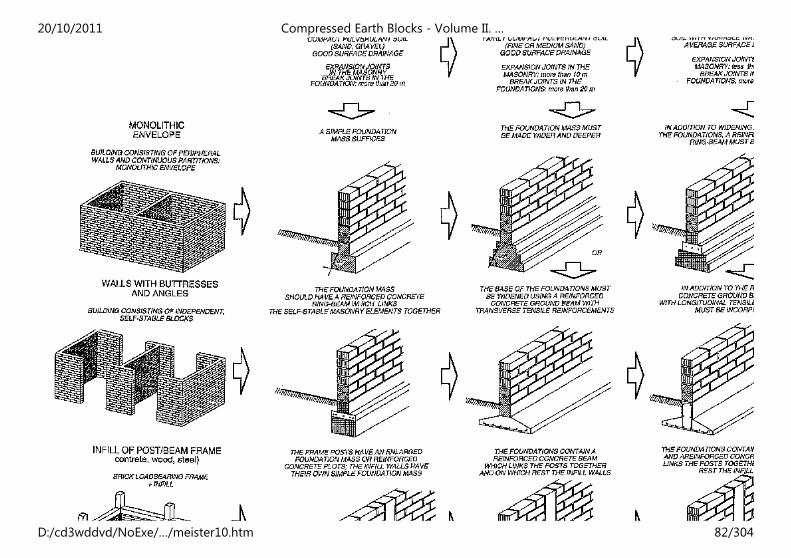
20/10/2011 Compressed Earth Blocks - Volume II. …
D:/cd3wddvd/NoExe/…/meister10.htm 82/304
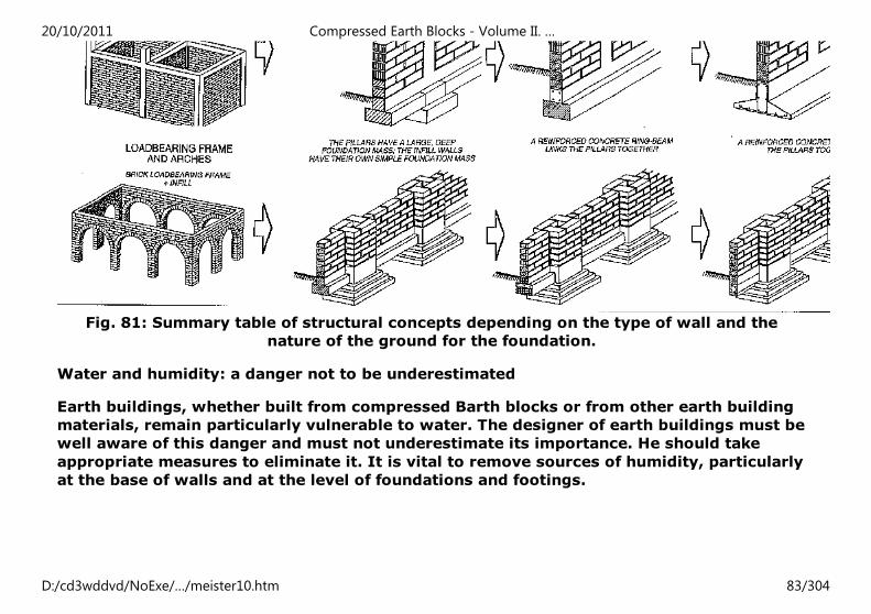
Fig. 81: Summary table of structural concepts depending on the type of wall and the
nature of the ground for the foundation.
Water and humidity: a danger not to be underestimated
Earth buildings, whether built from compressed Barth blocks or from other earth building
materials, remain particularly vulnerable to water. The designer of earth buildings must be
well aware of this danger and must not underestimate its importance. He should take
appropriate measures to eliminate it. It is vital to remove sources of humidity, particularly
at the base of walls and at the level of foundations and footings.
20/10/2011 Compressed Earth Blocks - Volume II. …
D:/cd3wddvd/NoExe/…/meister10.htm 83/304
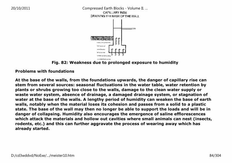
Fig. 82: Weakness due to prolonged exposure to humidity
Problems with foundations
At the base of the walls, from the foundations upwards, the danger of capillary rise can
stem from several sources: seasonal fluctuations in the water table, water retention by
plants or shrubs growing too close to the walls, damage to the clean water supply or
waste water system, absence of drainage, a damaged drainage system, or stagnation of
water at the base of the walls. A lengthy period of humidity can weaken the base of earth
walls, notably when the material loses its cohesion and passes from a solid to a plastic
state. The base of the wall may then no longer be able to support the loads and will be in
danger of collapsing. Humidity also encourages the emergence of saline efflorescences
which attack the materials and hollow out cavities where small animals can nest (insects,
rodents, etc.) and this can further aggravate the process of wearing away which has
already started.
20/10/2011 Compressed Earth Blocks - Volume II. …
D:/cd3wddvd/NoExe/…/meister10.htm 84/304
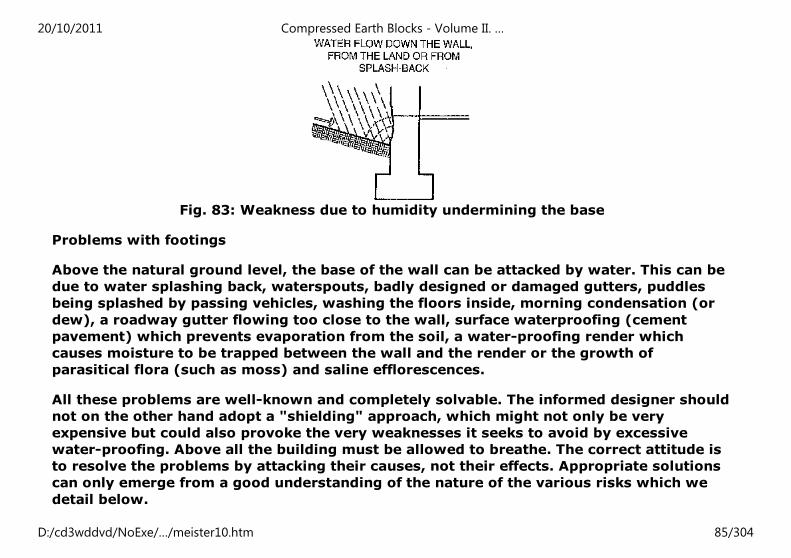
Fig. 83: Weakness due to humidity undermining the base
Problems with footings
Above the natural ground level, the base of the wall can be attacked by water. This can be
due to water splashing back, waterspouts, badly designed or damaged gutters, puddles
being splashed by passing vehicles, washing the floors inside, morning condensation (or
dew), a roadway gutter flowing too close to the wall, surface waterproofing (cement
pavement) which prevents evaporation from the soil, a water-proofing render which
causes moisture to be trapped between the wall and the render or the growth of
parasitical flora (such as moss) and saline efflorescences.
All these problems are well-known and completely solvable. The informed designer should
not on the other hand adopt a "shielding" approach, which might not only be very
expensive but could also provoke the very weaknesses it seeks to avoid by excessive
water-proofing. Above all the building must be allowed to breathe. The correct attitude is
to resolve the problems by attacking their causes, not their effects. Appropriate solutions
can only emerge from a good understanding of the nature of the various risks which we
detail below.
20/10/2011 Compressed Earth Blocks - Volume II. …
D:/cd3wddvd/NoExe/…/meister10.htm 85/304
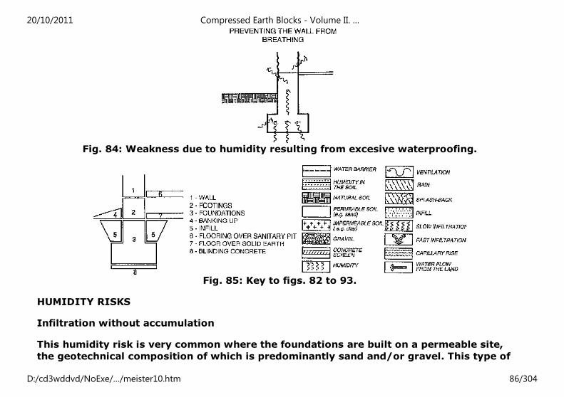
Fig. 84: Weakness due to humidity resulting from excesive waterproofing.
Fig. 85: Key to figs. 82 to 93.
HUMIDITY RISKS
Infiltration without accumulation
This humidity risk is very common where the foundations are built on a permeable site,
the geotechnical composition of which is predominantly sand and/or gravel. This type of
20/10/2011 Compressed Earth Blocks - Volume II. …
D:/cd3wddvd/NoExe/…/meister10.htm 86/304
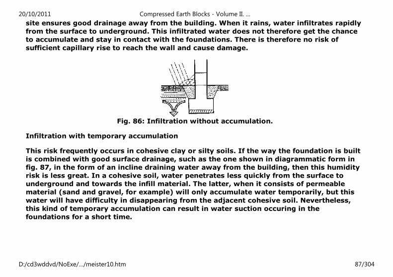
site ensures good drainage away from the building. When it rains, water infiltrates rapidly
from the surface to underground. This infiltrated water does not therefore get the chance
to accumulate and stay in contact with the foundations. There is therefore no risk of
sufficient capillary rise to reach the wall and cause damage.
Fig. 86: Infiltration without accumulation.
Infiltration with temporary accumulation
This risk frequently occurs in cohesive clay or silty soils. If the way the foundation is built
is combined with good surface drainage, such as the one shown in diagrammatic form in
fig. 87, in the form of an incline draining water away from the building, then this humidity
risk is less great. In a cohesive soil, water penetrates less quickly from the surface to
underground and towards the infill material. The latter, when it consists of permeable
material (sand and gravel, for example) will only accumulate water temporarily, but this
water will have difficulty in disappearing from the adjacent cohesive soil. Nevertheless,
this kind of temporary accumulation can result in water suction occuring in the
foundations for a short time.
20/10/2011 Compressed Earth Blocks - Volume II. …
D:/cd3wddvd/NoExe/…/meister10.htm 87/304
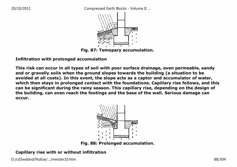
Fig. 87: Temopary accumulation.
Infiltration with prolonged accumulation
This risk can occur in all types of soil with poor surface drainage, even permeable, sandy
and or gravelly soils when the ground slopes towards the building (a situation to be
avoided at all costs). In this event, the slope acts as a captor and accumulator of water,
which then stays in prolonged contact with the foundations. Capillary rise follows, and this
can be significant during the rainy season. This capillary rise, depending on the design of
the building, can even reach the footings and the base of the wall. Serious damage can
occur.
Fig. 88: Prolonged accumulation.
Capillary rise with or without infiltration
20/10/2011 Compressed Earth Blocks - Volume II. …
D:/cd3wddvd/NoExe/…/meister10.htm 88/304
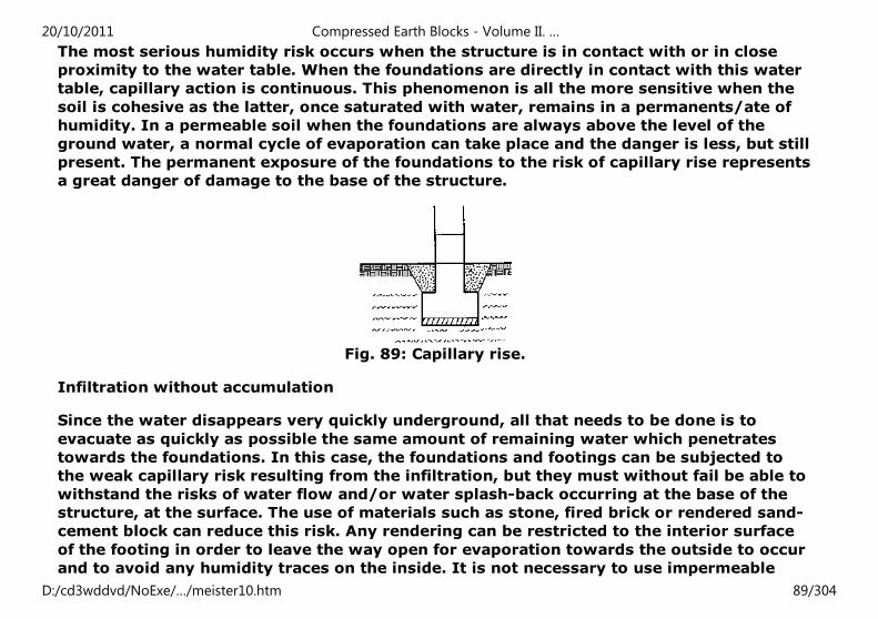
The most serious humidity risk occurs when the structure is in contact with or in close
proximity to the water table. When the foundations are directly in contact with this water
table, capillary action is continuous. This phenomenon is all the more sensitive when the
soil is cohesive as the latter, once saturated with water, remains in a permanents/ate of
humidity. In a permeable soil when the foundations are always above the level of the
ground water, a normal cycle of evaporation can take place and the danger is less, but still
present. The permanent exposure of the foundations to the risk of capillary rise represents
a great danger of damage to the base of the structure.
Fig. 89: Capillary rise.
Infiltration without accumulation
Since the water disappears very quickly underground, all that needs to be done is to
evacuate as quickly as possible the same amount of remaining water which penetrates
towards the foundations. In this case, the foundations and footings can be subjected to
the weak capillary risk resulting from the infiltration, but they must without fail be able to
withstand the risks of water flow and/or water splash-back occurring at the base of the
structure, at the surface. The use of materials such as stone, fired brick or rendered sand-
cement block can reduce this risk. Any rendering can be restricted to the interior surface
of the footing in order to leave the way open for evaporation towards the outside to occur
and to avoid any humidity traces on the inside. It is not necessary to use impermeable
20/10/2011 Compressed Earth Blocks - Volume II. …
D:/cd3wddvd/NoExe/…/meister10.htm 89/304
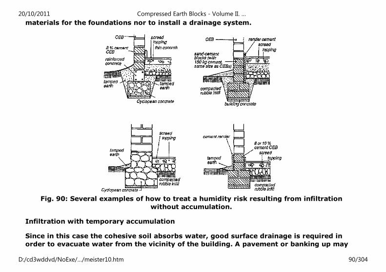
materials for the foundations nor to install a drainage system.
Fig. 90: Several examples of how to treat a humidity risk resulting from infiltration
without accumulation.
Infiltration with temporary accumulation
Since in this case the cohesive soil absorbs water, good surface drainage is required in
order to evacuate water from the vicinity of the building. A pavement or banking up may
20/10/2011 Compressed Earth Blocks - Volume II. …
D:/cd3wddvd/NoExe/…/meister10.htm 90/304
suffice but care must be taken not to make these impermeable to migrations of humidity
or moisture. This is unfortunately what often occurs when, with the best of intentions, a
pavement made of too high dosage cement is built. This prevents even the small amount
of water which remains at the level of the foundations from escaping, since it is trapped
by the impermeable surface and so naturally moves towards the footings and the base of
the wall. There is no need to use an impermeable render, or even a bitumen one, on the
vertical face of the foundations, nor to build impermeable foundations, nor even a deep
drainage system, since the water accumulation is only temporary. The structure must be
allowed to breathe.
20/10/2011 Compressed Earth Blocks - Volume II. …
D:/cd3wddvd/NoExe/…/meister10.htm 91/304
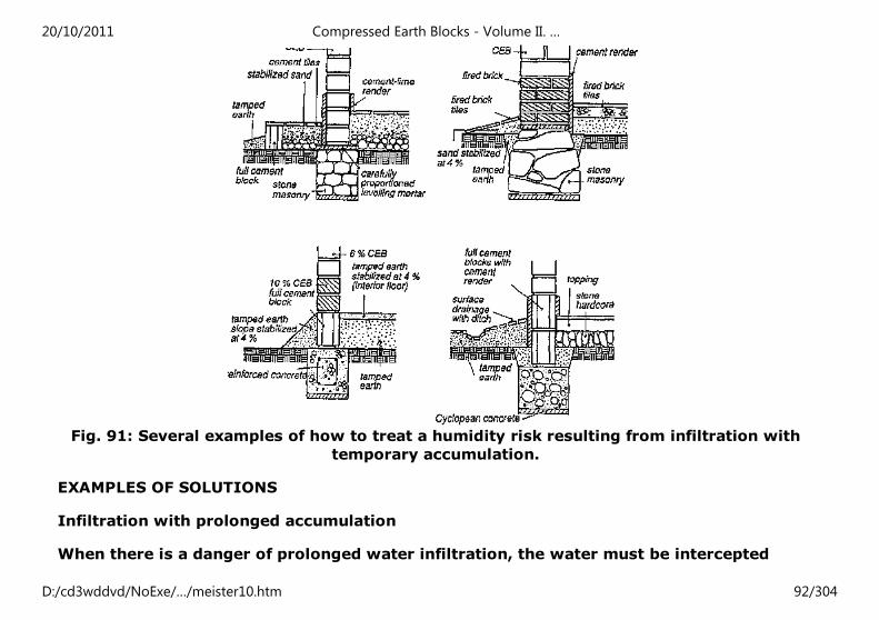
Fig. 91: Several examples of how to treat a humidity risk resulting from infiltration with
temporary accumulation.
EXAMPLES OF SOLUTIONS
Infiltration with prolonged accumulation
When there is a danger of prolonged water infiltration, the water must be intercepted
20/10/2011 Compressed Earth Blocks - Volume II. …
D:/cd3wddvd/NoExe/…/meister10.htm 92/304
before it penetrates underground and evacuated as quickly as possible. The principle of
drainage is perfectly appropriate here. Drains can be built right against the foundations
but then the external vertical surface of the foundations will have to be rendered or made
impermeable. They can also be installed at a distance in the order of one metre from the
foundations, but on condition that they are located deeper than the foundations. These
more distant drains are more efficient if they are used in conjunction with an evacuation
incline at the base of the wall and if the top layer of the drain layer is bowl-shaped to aid
evacuation. It is also prudent to add a horizontal anti-capillary barrier (e.g. polythene,
bitumen, or high dosage mortar) between the footing and the earth block wall.
20/10/2011 Compressed Earth Blocks - Volume II. …
D:/cd3wddvd/NoExe/…/meister10.htm 93/304
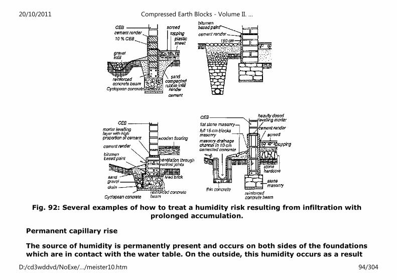
Fig. 92: Several examples of how to treat a humidity risk resulting from infiltration with
prolonged accumulation.
Permanent capillary rise
The source of humidity is permanently present and occurs on both sides of the foundations
which are in contact with the water table. On the outside, this humidity occurs as a result
20/10/2011 Compressed Earth Blocks - Volume II. …
D:/cd3wddvd/NoExe/…/meister10.htm 94/304
of the accumulated effect of rain and capillary rise. On the inside, it occurs as a result of
capillary rise. Drains must be built against the foundations (which should be water-
resistant) and even under the floor covering of the ground-floor if this is directly on the
ground. Distant drains are not recommended. Water-proof horizontal barriers are also
needed between the footing and the earth block wall. If the floor covering is directly on
the ground it can be laid on a water-proof film which is itself unrolled on a rough surface
of stones and rolled gravel which acts as an anti-capillary barrier. It is preferable to
previously dig up the ground supporting the building and make sure that some permeable
materials (e.g. gravelly-sandy soil) are present. If the building is over a sanitary pit, this
must be ventilated.
20/10/2011 Compressed Earth Blocks - Volume II. …
D:/cd3wddvd/NoExe/…/meister10.htm 95/304
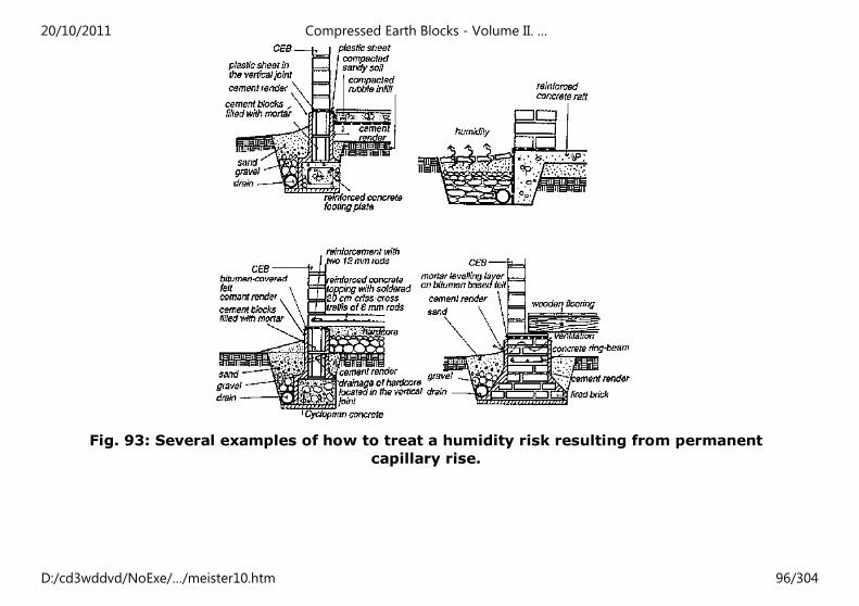
Fig. 93: Several examples of how to treat a humidity risk resulting from permanent
capillary rise.
20/10/2011 Compressed Earth Blocks - Volume II. …
D:/cd3wddvd/NoExe/…/meister10.htm 96/304
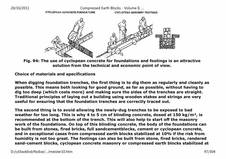
Fig. 94: The use of cyclopean concrete for foundations and footings is an attractive
solution from the technical and economic point of view.
Choice of materials and specifications
When digging foundation trenches, the first thing is to dig them as regularly and cleanly as
possible. This means both looking for good ground, as far as possible, without having to
dig too deep (which costs more) and making sure the sides of the trenches are straight.
Traditional principles of laying out a building using wooden stakes and strings are very
useful for ensuring that the foundation trenches are correctly traced out.
The second thing is to avoid allowing the newly-dug trenches to be exposed to bad
weather for too long. This is why 4 to 5 cm of blinding concrete, dosed at 150 kg/m³, is
recommended at the bottom of the trench. This will also help to start off the masonry
work of the foundations. On top of this blinding concrete, the body of the foundations can
be built from stones, fired bricks, full sandcementblocks, cement or cyclopean concrete,
and in exceptional cases from compressed earth blocks stabilized at 10% if the risk from
humidity is not too great. The footings can also be built from stone, fired bricks, rendered
sand-cement blocks, cyclopean concrete masonry or compressed earth blocks stabilized at
20/10/2011 Compressed Earth Blocks - Volume II. …
D:/cd3wddvd/NoExe/…/meister10.htm 97/304
8% there is not too much risk of humidity occuring as result of splashback. Concrete
foundations should be dosed at 200 kg/m³; if they contain reinforcement, at 250 kg/m³;
and if they consist in a reinforced concrete footing plate or ground-beam, at 300 kg/m³.
In the latter case, the quantity of steel can be estimated at between 50 and 70 kg/m³,
including 25 to 40 kg for the transverse reinforcement which absorbs tensile stress.
Using cyclopean concrete
For cyclopean concrete foundations, rubble stones are incorporated in successive layers of
cement mortar which coats each layer of stone with a covering at least 3 cm thick. This
type of structure is perfectly suitable for. a low-cost construction on good ground, but
must be well done. Notably, the rubble stones should not touch each other, nor be located
only at the sides of the foundations, in which case the central part of the foundation would
be filled only with mortar, giving a weak structure.
Stones which take up the whole width of the foundation should be laid at regular intervals,
forming a kind of toothing.
The other aspect to be considered is how much cement to use in cyclopean concrete which
should be dosed at 250 kg/m³ (250 kg of cement, 400 litres of sand and 800 litres of
gravel). Once the rubble stones have been laid in layers of concrete, 1 m³ of cyclopean
concrete ultimately contains less cement that solid concrete (approximately 125 kg) which
is interesting from an economic point of view. All in cases, the total width of the
foundations should be at least 40 cm, and at least 20 cm thicker than the wall thickness,
divided between both sides of the wall faces starting from the longitudinal axis. The height
of the body of the foundations should be at least equal to half the width. If the foundations
require an anticapillary water-proof layer, this can be made using highly dosed cement
mortar (500 kg/m³), bitumen-based paint or a bitumen or plastic film if these materials
are available.
20/10/2011 Compressed Earth Blocks - Volume II. …
D:/cd3wddvd/NoExe/…/meister10.htm 98/304
Cyclopean concrete can continue to be used for the footings ; above the foundations, in
which case the cyclopean concrete must be shuttered and the stones placed right up
against the shuttering. The principle of toothing stones (approximately every 60 cm and in
alternate rows - one at each corner and one in the middle) to ensure the solidity of a
cyclopean concrete footing should be carefully checked on site.
Ring-beam at foundation level
When building on poor soils which are unstable and which may cause differential settling,
a foundation ring-beam is recommended. This will stabilize the sides against potential
movement in the foundations. These movements are essentially vertical, and as a result
the foundation ring-beam will be designed like a beam with vertical bending moment.
Such a ring-beam therefore has to be a beam with reinforcement running from top to
bottom. At the same time if the body of the foundations is mainly built from masonry, it is
possible to reduce the amount of steel used. By locating the reinforced concrete ring-beam
halfway up the body of the foundations, one can assume that there is an area of
compression above and below this reinforced steel and the whole can therefore act in both
directions. This means using masonry which has perfect compressive strength and hollow
sand-cement blocks cannot be used.
MATERIALS AND SPECIFICATIONS
To take one example, 3 cm² steel rods or 2 cm² high adherence steel rods, can be
sufficient. The concrete coating of these steel rods should be at least 4 cm thick. The
height of the reinforced ring-beam can therefore be reduced to 10 cm using 212 rods or
310 rods. The cement dosage should be a minimum of 250 kg/m³.
The principle of using a ring-beam in the foundations cannot be applied to small, single-
storey buildings founded on good to medium strength soils (rocky soils, compact sandy-
gravelly soils, or cohesive soils) and if loads are evenly distributed. In other cases, it is
20/10/2011 Compressed Earth Blocks - Volume II. …
D:/cd3wddvd/NoExe/…/meister10.htm 99/304
preferable to use the solution of a reinforced concrete ringbeam which is integrated into
the foundations.
Openings
Good structural bonding
Care should be taken with the structural bonding of frame openings with CEB walls in
order to limit the danger of cracking which could lead to water infiltration and therefore a
process of erosion.
Structural weaknesses of openings
It is important to compensate for shearing stress loads to the lower edge which is
transmitted directly down the jambs of the reveals from the lintels.
The following classic mistakes should be avoided:
- making openings too big, placing too great load a on the lintel;
- too many openings of too many different sizes on the same wall, which weakens
the wall;
- locating an opening immediately next to the corner of a building, making the
corner buckle;
- two openings too close together with too slender an intermediate pier, making
the pier buckle;
- insufficiently strong frame jambs, leading to buckling;
- insufficient anchoring of the lintel or of the supporting base into the wall, leading
to shearing;
- poor earth block bonding patterns near the openings, leading to cracking through
superimposed vertical joints.
20/10/2011 Compressed Earth Blocks - Volume II. …
D:/cd3wddvd/NoExe/…/meister10.htm 100/304
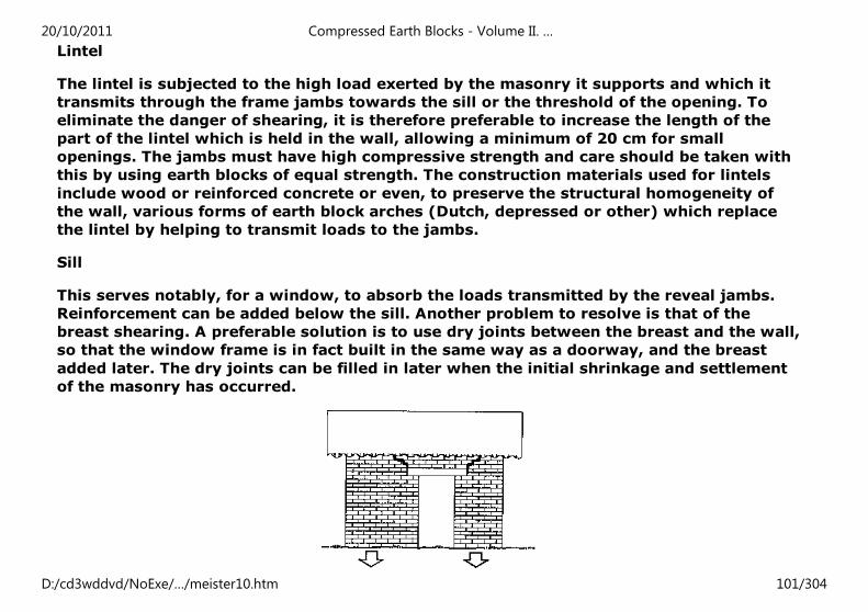
Lintel
The lintel is subjected to the high load exerted by the masonry it supports and which it
transmits through the frame jambs towards the sill or the threshold of the opening. To
eliminate the danger of shearing, it is therefore preferable to increase the length of the
part of the lintel which is held in the wall, allowing a minimum of 20 cm for small
openings. The jambs must have high compressive strength and care should be taken with
this by using earth blocks of equal strength. The construction materials used for lintels
include wood or reinforced concrete or even, to preserve the structural homogeneity of
the wall, various forms of earth block arches (Dutch, depressed or other) which replace
the lintel by helping to transmit loads to the jambs.
Sill
This serves notably, for a window, to absorb the loads transmitted by the reveal jambs.
Reinforcement can be added below the sill. Another problem to resolve is that of the
breast shearing. A preferable solution is to use dry joints between the breast and the wall,
so that the window frame is in fact built in the same way as a doorway, and the breast
added later. The dry joints can be filled in later when the initial shrinkage and settlement
of the masonry has occurred.
20/10/2011 Compressed Earth Blocks - Volume II. …
D:/cd3wddvd/NoExe/…/meister10.htm 101/304
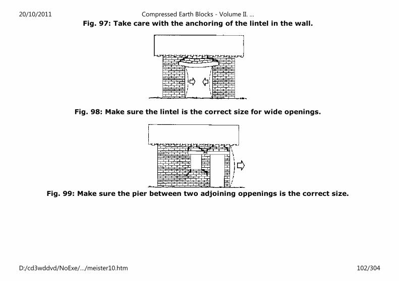
Fig. 97: Take care with the anchoring of the lintel in the wall.
Fig. 98: Make sure the lintel is the correct size for wide openings.
Fig. 99: Make sure the pier between two adjoining oppenings is the correct size.
20/10/2011 Compressed Earth Blocks - Volume II. …
D:/cd3wddvd/NoExe/…/meister10.htm 102/304
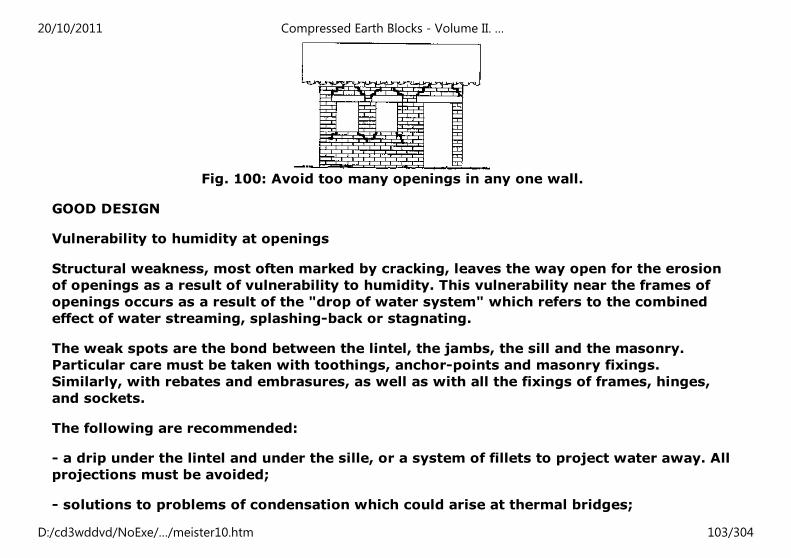
Fig. 100: Avoid too many openings in any one wall.
GOOD DESIGN
Vulnerability to humidity at openings
Structural weakness, most often marked by cracking, leaves the way open for the erosion
of openings as a result of vulnerability to humidity. This vulnerability near the frames of
openings occurs as a result of the "drop of water system" which refers to the combined
effect of water streaming, splashing-back or stagnating.
The weak spots are the bond between the lintel, the jambs, the sill and the masonry.
Particular care must be taken with toothings, anchor-points and masonry fixings.
Similarly, with rebates and embrasures, as well as with all the fixings of frames, hinges,
and sockets.
The following are recommended:
- a drip under the lintel and under the sille, or a system of fillets to project water away. All
projections must be avoided;
- solutions to problems of condensation which could arise at thermal bridges;
20/10/2011 Compressed Earth Blocks - Volume II. …
D:/cd3wddvd/NoExe/…/meister10.htm 103/304
- reinforced stabilization, rendering, or covering joints in the external facade, flush with
the sides of the openings (in high rainfall regions);
- water-proofing under the sill.
Dimensioning the openings
There are certain rules for dimensioning the openings in an earth masonry structure,
which do not preclude variety in the design of their shape and size.
- In any one wall, the ratio of voids to total surface area should not exceed 1:3 and voids
should be evenly spaced. Too great a concentration of voids or openings which are too
large should be avoided, unless the structure has been designed with these in mind.
- The overall length of openings should not exceed 35% of the length of the wall.
- Standard opening spans should be restricted to 1.20 m for standard section lintels. For
wider openings, the lintel must be increased in size and it must be more deeply anchored
into the wall.
- The minimal distance between an opening and the corner of a building should be 1 m.
This distance can, however, be reduced by taking appropriate measures in the
construction.
- The width of a pier common to two openings should not be less that the thickness of the
wall and should be equivalent to a minimum of 60 cm (two standard blocks). The pier is
not loadbearing unless it exceeds 1 m in width (lintel common to two openings for a less
wide pier).
- The height of the masonry above the lintel and of the breast below the supporting base
20/10/2011 Compressed Earth Blocks - Volume II. …
D:/cd3wddvd/NoExe/…/meister10.htm 104/304

should respect a balanced ratio depending on the width of the opening.
Fig. 101: Vulnerability to humidity: the "drop of water" system
Fig. 102: Rules for dimensioning openings.
20/10/2011 Compressed Earth Blocks - Volume II. …
D:/cd3wddvd/NoExe/…/meister10.htm 105/304
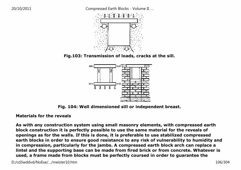
Fig.103: Transmission of loads, cracks at the sill.
Fig. 104: Well dimensioned sill or independent breast.
Materials for the reveals
As with any construction system using small masonry elements, with compressed earth
block construction it is perfectly possible to use the same material for the reveals of
openings as for the walls. If this is done, it is preferable to use stabilized compressed
earth blocks in order to ensure good resistance to any risk of vulnerability to humidity and
in compression, particularly for the jambs. A compressed earth block arch can replace a
lintel and the supporting base can be made from fired brick or from concrete. Whatever is
used, a frame made from blocks must be perfectly coursed in order to guarantee the
20/10/2011 Compressed Earth Blocks - Volume II. …
D:/cd3wddvd/NoExe/…/meister10.htm 106/304
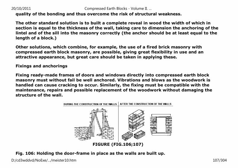
quality of the bonding and thus overcome the risk of structural weakness.
The other standard solution is to built a complete reveal in wood the width of which in
section is equal to the thickness of the wall, taking care to dimension the anchoring of the
lintel and of the sill into the masonry correctly (the anchor should be at least equal to the
length of a block.)
Other solutions, which combine, for example, the use of a fired brick masonry with
compressed earth block masonry, are possible, giving great flexibility in use and an
attractive appearance, but great care should be taken in applying these.
Fixings and anchorings
Fixing ready-made frames of doors and windows directly into compressed earth block
masonry must without fail be well anchored. Vibrations and blows as the woodwork is
handled can cause cracking to occur. Similarly, the fixing must be compatible with the
maintenance, repairs and possible replacement of the woodwork without damaging the
structure of the wall.
FIGURE (FIG.106;107)
Fig. 106: Holding the door-frame in place as the walls are built up.
20/10/2011 Compressed Earth Blocks - Volume II. …
D:/cd3wddvd/NoExe/…/meister10.htm 107/304
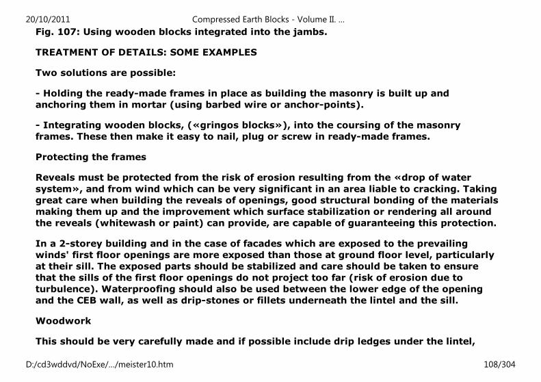
Fig. 107: Using wooden blocks integrated into the jambs.
TREATMENT OF DETAILS: SOME EXAMPLES
Two solutions are possible:
- Holding the ready-made frames in place as building the masonry is built up and
anchoring them in mortar (using barbed wire or anchor-points).
- Integrating wooden blocks, («gringos blocks»), into the coursing of the masonry
frames. These then make it easy to nail, plug or screw in ready-made frames.
Protecting the frames
Reveals must be protected from the risk of erosion resulting from the «drop of water
system», and from wind which can be very significant in an area liable to cracking. Taking
great care when building the reveals of openings, good structural bonding of the materials
making them up and the improvement which surface stabilization or rendering all around
the reveals (whitewash or paint) can provide, are capable of guaranteeing this protection.
In a 2-storey building and in the case of facades which are exposed to the prevailing
winds' first floor openings are more exposed than those at ground floor level, particularly
at their sill. The exposed parts should be stabilized and care should be taken to ensure
that the sills of the first floor openings do not project too far (risk of erosion due to
turbulence). Waterproofing should also be used between the lower edge of the opening
and the CEB wall, as well as drip-stones or fillets underneath the lintel and the sill.
Woodwork
This should be very carefully made and if possible include drip ledges under the lintel,
20/10/2011 Compressed Earth Blocks - Volume II. …
D:/cd3wddvd/NoExe/…/meister10.htm 108/304
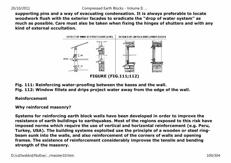
supporting pins and a way of evacuating condensation. It is always preferable to locate
woodwork flush with the exterior facades to eradicate the “drop of water system” as
much as possible. Care must also be taken when fixing the hinges of shutters and with any
kind of external occultation.
FIGURE (FIG.111;112)
Fig. 111: Reinforcing water-proofing between the bases and the wall.
Fig. 112: Window fillets and drips project water away from the edge of the wall.
Reinforcement
Why reinforced masonry?
Systems for reinforcing earth block walls have been developed in order to improve the
resistance of earth buildings to earthquakes. Most of the regions exposed to this risk have
imposed norms which require the use of vertical and horizontal reinforcement (e.g. Peru,
Turkey, USA). The building systems exploited use the principle of a wooden or steel ring-
beam sunk into the walls, and also reinforcement of the corners of walls and opening
frames. The existence of reinforcement considerably improves the tensile and bending
strength of the masonry.
20/10/2011 Compressed Earth Blocks - Volume II. …
D:/cd3wddvd/NoExe/…/meister10.htm 109/304
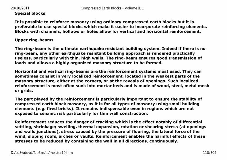
Special blocks
It is possible to reinforce masonry using ordinary compressed earth blocks but it is
preferable to use special blocks which make it easier to incorporate reinforcing elements.
Blocks with channels, hollows or holes allow for vertical and horizontal reinforcement.
Upper ring-beams
The ring-beam is the ultimate earthquake resistant building system. Indeed if there is no
ring-beam, any other earthquake resistant building approach is rendered practically
useless, particularly with thin, high walls. The ring-beam ensures good transmission of
loads and allows a highly organized masonry structure to be formed.
Horizontal and vertical ring-beams are the reinforcement systems most used. They can
sometimes consist in very localized reinforcement, located in the weakest parts of the
masonry structure, either at the corners, or at the reveals of openings. Such localized
reinforcement is most often sunk into mortar beds and is made of wood, steel, metal mesh
or grids.
The part played by the reinforcement is particularly important to ensure the stability of
compressed earth block masonry, as it is for all types of masonry using small building
elements (e.g. fired bricks). It remains indispensable even in regions which are not
exposed to seismic risk particularly for thin wall construction.
Reinforcement reduces the danger of cracking which is the effect notably of dlfferential
settling, shrinkage; swelling, thermal expansion, rotation or shearing stress (at openings
and walls junctions), stress caused by the pressure of flooring, the lateral force of the
wind, sloping roofs, arches or vaults. Reinforcement enables the harmful effects of these
stresses to be reduced by containing the wall in all directions, continuously.
20/10/2011 Compressed Earth Blocks - Volume II. …
D:/cd3wddvd/NoExe/…/meister10.htm 110/304
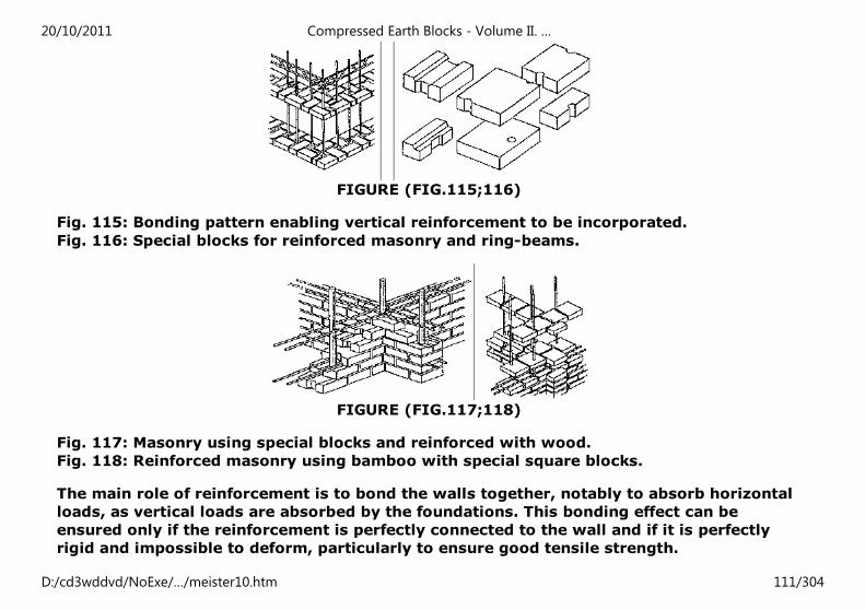
FIGURE (FIG.115;116)
Fig. 115: Bonding pattern enabling vertical reinforcement to be incorporated.
Fig. 116: Special blocks for reinforced masonry and ring-beams.
FIGURE (FIG.117;118)
Fig. 117: Masonry using special blocks and reinforced with wood.
Fig. 118: Reinforced masonry using bamboo with special square blocks.
The main role of reinforcement is to bond the walls together, notably to absorb horizontal
loads, as vertical loads are absorbed by the foundations. This bonding effect can be
ensured only if the reinforcement is perfectly connected to the wall and if it is perfectly
rigid and impossible to deform, particularly to ensure good tensile strength.
20/10/2011 Compressed Earth Blocks - Volume II. …
D:/cd3wddvd/NoExe/…/meister10.htm 111/304
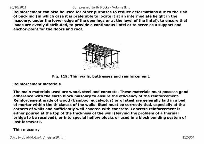
Reinforcement can also be used for other purposes to reduce deformations due to the risk
of buckling (in which case it is preferable to locate it at an intermediate height in the
masonry, under the lower edge of the openings or at the level of the lintel), to ensure that
loads are evenly distributed, to provide a continuous lintel or to serve as a support and
anchor-point for the floors and roof.
Fig. 119: Thin walls, buttresses and reinforcement.
Reinforcement materials
The main materials used are wood, steel and concrete. These materials must possess good
adherence with the earth block masonry to ensure the efficiency of the reinforcement.
Reinforcement made of wood (bamboo, eucalyptus) or of steel are generally laid in a bed
of mortar within the thickness of the walls. Steel must be correctly tied, especially at the
corners of walls and sufficiently well covered with concrete. Concrete reinforcement is
either poured at the top of the thickness of the wall (leaving the problem of a thermal
bridge to be resolved), or into special hollow blocks or used in a block bonding system of
lost formwork.
Thin masonry
20/10/2011 Compressed Earth Blocks - Volume II. …
D:/cd3wddvd/NoExe/…/meister10.htm 112/304
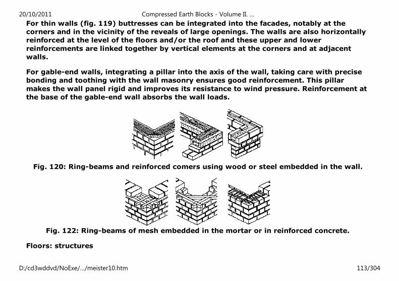
For thin walls (fig. 119) buttresses can be integrated into the facades, notably at the
corners and in the vicinity of the reveals of large openings. The walls are also horizontally
reinforced at the level of the floors and/or the roof and these upper and lower
reinforcements are linked together by vertical elements at the corners and at adjacent
walls.
For gable-end walls, integrating a pillar into the axis of the wall, taking care with precise
bonding and toothing with the wall masonry ensures good reinforcement. This pillar
makes the wall panel rigid and improves its resistance to wind pressure. Reinforcement at
the base of the gable-end wall absorbs the wall loads.
Fig. 120: Ring-beams and reinforced comers using wood or steel embedded in the wall.
Fig. 122: Ring-beams of mesh embedded in the mortar or in reinforced concrete.
Floors: structures
20/10/2011 Compressed Earth Blocks - Volume II. …
D:/cd3wddvd/NoExe/…/meister10.htm 113/304
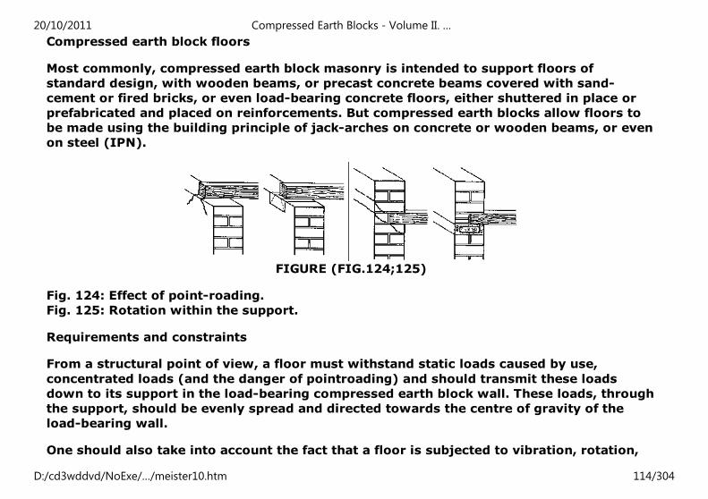
Compressed earth block floors
Most commonly, compressed earth block masonry is intended to support floors of
standard design, with wooden beams, or precast concrete beams covered with sand-
cement or fired bricks, or even load-bearing concrete floors, either shuttered in place or
prefabricated and placed on reinforcements. But compressed earth blocks allow floors to
be made using the building principle of jack-arches on concrete or wooden beams, or even
on steel (IPN).
FIGURE (FIG.124;125)
Fig. 124: Effect of point-roading.
Fig. 125: Rotation within the support.
Requirements and constraints
From a structural point of view, a floor must withstand static loads caused by use,
concentrated loads (and the danger of pointroading) and should transmit these loads
down to its support in the load-bearing compressed earth block wall. These loads, through
the support, should be evenly spread and directed towards the centre of gravity of the
load-bearing wall.
One should also take into account the fact that a floor is subjected to vibration, rotation,
20/10/2011 Compressed Earth Blocks - Volume II. …
D:/cd3wddvd/NoExe/…/meister10.htm 114/304
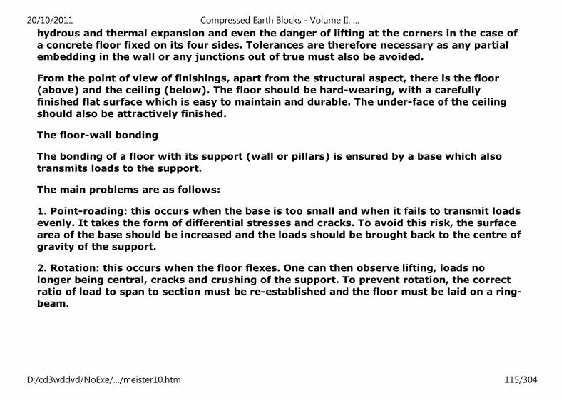
hydrous and thermal expansion and even the danger of lifting at the corners in the case of
a concrete floor fixed on its four sides. Tolerances are therefore necessary as any partial
embedding in the wall or any junctions out of true must also be avoided.
From the point of view of finishings, apart from the structural aspect, there is the floor
(above) and the ceiling (below). The floor should be hard-wearing, with a carefully
finished flat surface which is easy to maintain and durable. The under-face of the ceiling
should also be attractively finished.
The floor-wall bonding
The bonding of a floor with its support (wall or pillars) is ensured by a base which also
transmits loads to the support.
The main problems are as follows:
1. Point-roading: this occurs when the base is too small and when it fails to transmit loads
evenly. It takes the form of differential stresses and cracks. To avoid this risk, the surface
area of the base should be increased and the loads should be brought back to the centre of
gravity of the support.
2. Rotation: this occurs when the floor flexes. One can then observe lifting, loads no
longer being central, cracks and crushing of the support. To prevent rotation, the correct
ratio of load to span to section must be re-established and the floor must be laid on a ring-
beam.
20/10/2011 Compressed Earth Blocks - Volume II. …
D:/cd3wddvd/NoExe/…/meister10.htm 115/304
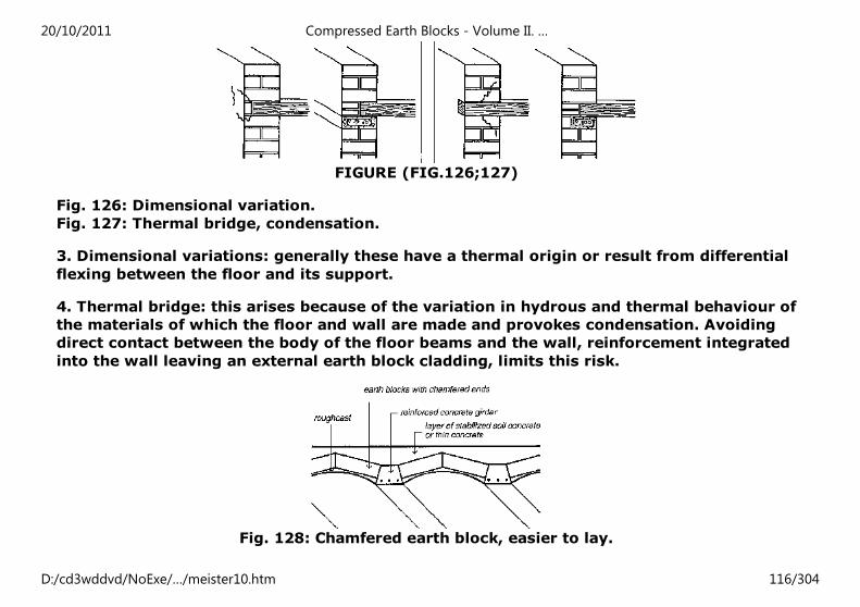
FIGURE (FIG.126;127)
Fig. 126: Dimensional variation.
Fig. 127: Thermal bridge, condensation.
3. Dimensional variations: generally these have a thermal origin or result from differential
flexing between the floor and its support.
4. Thermal bridge: this arises because of the variation in hydrous and thermal behaviour of
the materials of which the floor and wall are made and provokes condensation. Avoiding
direct contact between the body of the floor beams and the wall, reinforcement integrated
into the wall leaving an external earth block cladding, limits this risk.
Fig. 128: Chamfered earth block, easier to lay.
20/10/2011 Compressed Earth Blocks - Volume II. …
D:/cd3wddvd/NoExe/…/meister10.htm 116/304
Laying the floors
The best way to ensure that floors are carefully laid is to leave gaps beforehand to receive
the beams or their bases in the wall. This problem should be taken into account as soon as
the working plans for the structure are being prepared, notably during the coursing of the
building plans. On site, the most important problem to resolve is that of protecting the
floor structures from rain in order to avoid any water infiltration.
Jack arches and vaulting
Jack arches and vaulting
A compressed earth block floor made of jack arches acts like lost formwork. This is a
solution which reduces the amount of sand, gravel, cement and reinforcements used
compared with concrete floor systems.
Vaulting floors have the advantage of making the compressed earth block work in
compression' with bending stresses being taken up by the wooden, concrete or steel
beams or struts. The span for receiving the beams varies from 0.50 m for small systems to
2 m for the largest which can require the use of metal tie-rods. CEB vaulting rests on the
lower wings of the IPNs or on the spines of the concrete struts. A small curve (1/1 0 of
the span) allows the struts to take up the stresses well. The floor is finished by filling in
with stabilized earth concrete or light concrete. These floors are still, however, heavy, and
the load they exert must be evenly spread and transmitted to the bases.
Building vaulting can be done using formwork, most often sliding formwork, or without
shuttering using a laying technique similar to that of the Nubian vault (successive inclined
courses) or on a plank supported by props (located in the axis of the vault) and on which
the blocks are placed on either side of the axis (fig. 130).
20/10/2011 Compressed Earth Blocks - Volume II. …
D:/cd3wddvd/NoExe/…/meister10.htm 117/304
Roof classification
The importance of the roof
Compressed earth block structures must be protected by a good roof, particularly in
regions where the climate is marked by an heavy rainy season. The roof is the "good hat"
of compressed earth block structures. it diverts the flow of rain away from the wall and
plays an essential part in preserving it from the problem of humidity which is a major risk.
Using compressed earth blocks for the roof
Traditionally, in most of the regions of the world, the compressed earth block is only
rarely used to build roofs. Regions with a desert or semi-desert climate have inherited a
tradition of adobe roofs, in the form of vaults and domes, but changing to the use of
compressed earth blocks is not yet very marked. Over the last decades, architects and
builders have confirmed their interest in building roofs using earth blocks in several
projects, notably in contexts where the cost of traditional roofing materials (wood,
concrete) is an important handicap. Earth roofs have a definite economic advantage, as
the cost of the roof alone can reach up to 50% of the overall building cost.
Main roof types
Flat roofs
These are generally built following the floor principle described before, either using
wooden beams, concrete or steel struts and compressed earth block vaulting. The main
problems are waterproofing, thermal expansion (in hot climates), drainage of the flat roof
(minimum slope of 1 to 2%), evacuating water using suitable systems of spouts or
channels and protecting the edges of the roof with parapets.
20/10/2011 Compressed Earth Blocks - Volume II. …
D:/cd3wddvd/NoExe/…/meister10.htm 118/304
Sloping roofs
These are built in very conventional ways, with timber frame covered with tiles, felt or
corrugated iron sheets. The slope must be sufficiently great and the roof overhang must
be sufficiently wide (minimum 30 cm) for the rainwater to be projected away from the
wall. The main problems are those of the stability of the gable-end walls (slenderness
ratio) and the anchoring of the timber frame in the loadbearing walls (use of a ring-beam).
Curved roofs
These are built in the form of vaults or cupolas. The main problems are of the same kind as
those of flat roofs, notably water-proofing, thermal expansion and removing water away
from the walls. Peripheral protection is ensured by parapet systems.
COMPRESSED EARTH BLOCK ROOFS
An inherited tradition
Compressed earth block roofs are inherited from a tradition of adobe roofing developed in
regions with dry climates where good roofing timber was scarce (Mesopotamia, Egypt,
Iran). By building earth vaults and cupolas, builders were exploiting the inherent potential
of the material, i.e. its ability to work in compression. This type of roof also has an
undoubted aesthetic appeal both with regard to the architectural forms and the inner
spaces which architects and their clients find attractive.
The problem of stresses
Earth block roofs are generally heavy and exert very great lateral stresses on the walls,
which have to regain their verticality. The use of ring-beams, post-compression loads
(parapets), thick walls or buttresses, and sometimes tie-rods for wide span vaults,
20/10/2011 Compressed Earth Blocks - Volume II. …
D:/cd3wddvd/NoExe/…/meister10.htm 119/304
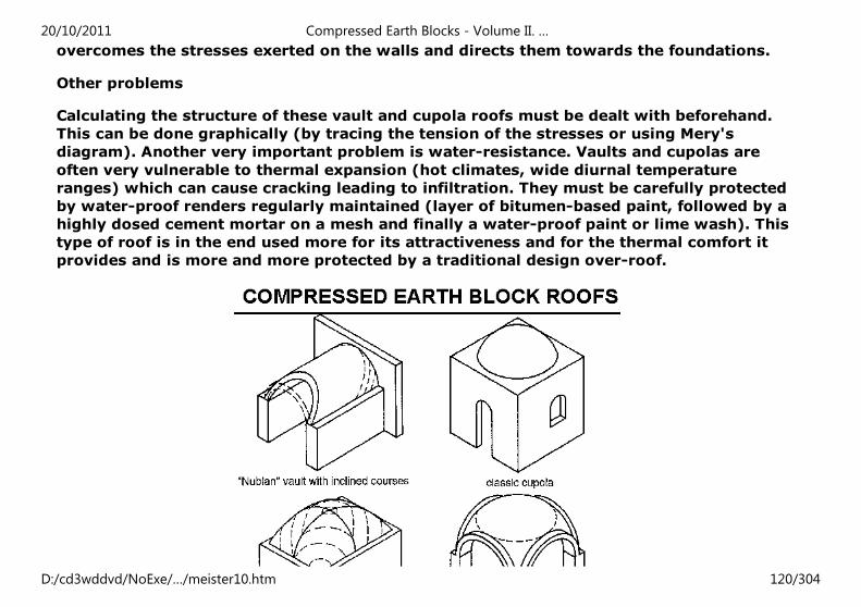
overcomes the stresses exerted on the walls and directs them towards the foundations.
Other problems
Calculating the structure of these vault and cupola roofs must be dealt with beforehand.
This can be done graphically (by tracing the tension of the stresses or using Mery's
diagram). Another very important problem is water-resistance. Vaults and cupolas are
often very vulnerable to thermal expansion (hot climates, wide diurnal temperature
ranges) which can cause cracking leading to infiltration. They must be carefully protected
by water-proof renders regularly maintained (layer of bitumen-based paint, followed by a
highly dosed cement mortar on a mesh and finally a water-proof paint or lime wash). This
type of roof is in the end used more for its attractiveness and for the thermal comfort it
provides and is more and more protected by a traditional design over-roof.
20/10/2011 Compressed Earth Blocks - Volume II. …
D:/cd3wddvd/NoExe/…/meister10.htm 120/304
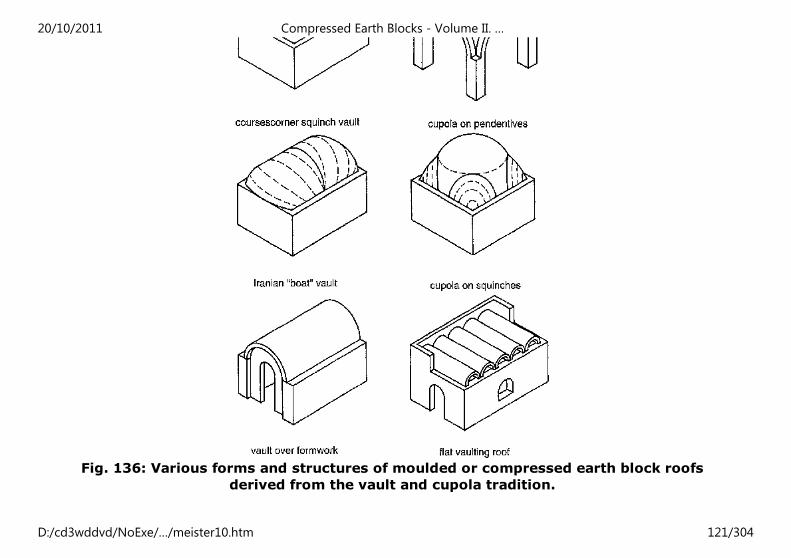
Fig. 136: Various forms and structures of moulded or compressed earth block roofs
derived from the vault and cupola tradition.
20/10/2011 Compressed Earth Blocks - Volume II. …
D:/cd3wddvd/NoExe/…/meister10.htm 121/304
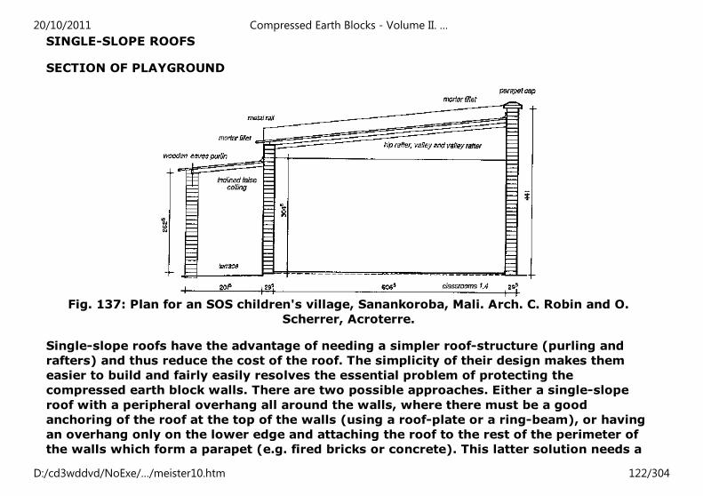
SINGLE-SLOPE ROOFS
SECTION OF PLAYGROUND
Fig. 137: Plan for an SOS children's village, Sanankoroba, Mali. Arch. C. Robin and O.
Scherrer, Acroterre.
Single-slope roofs have the advantage of needing a simpler roof-structure (purling and
rafters) and thus reduce the cost of the roof. The simplicity of their design makes them
easier to build and fairly easily resolves the essential problem of protecting the
compressed earth block walls. There are two possible approaches. Either a single-slope
roof with a peripheral overhang all around the walls, where there must be a good
anchoring of the roof at the top of the walls (using a roof-plate or a ring-beam), or having
an overhang only on the lower edge and attaching the roof to the rest of the perimeter of
the walls which form a parapet (e.g. fired bricks or concrete). This latter solution needs a
20/10/2011 Compressed Earth Blocks - Volume II. …
D:/cd3wddvd/NoExe/…/meister10.htm 122/304
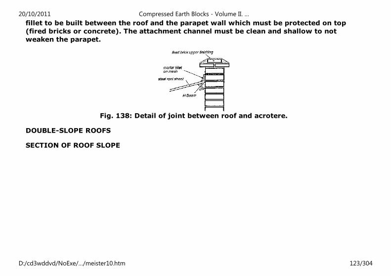
fillet to be built between the roof and the parapet wall which must be protected on top
(fired bricks or concrete). The attachment channel must be clean and shallow to not
weaken the parapet.
Fig. 138: Detail of joint between roof and acrotere.
DOUBLE-SLOPE ROOFS
SECTION OF ROOF SLOPE
20/10/2011 Compressed Earth Blocks - Volume II. …
D:/cd3wddvd/NoExe/…/meister10.htm 123/304
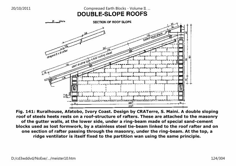
Fig. 141: Ruralhouse, Afatobo, Ivory Coast. Design by CRATerre, S. Maini. A double sloping
roof of steels heets rests on a roof-structure of rafters. These are attached to the masonry
of the gutter walls, at the lower side, under a ring-beam made of special sand-cement
blocks used as lost formwork, by a stainless steel tie-beam linked to the roof rafter and on
one section of rafter passing through the masonry, under the ring-beam. At the top, a
ridge ventilator is itself fixed to the partition wan using the same principle.
20/10/2011 Compressed Earth Blocks - Volume II. …
D:/cd3wddvd/NoExe/…/meister10.htm 124/304
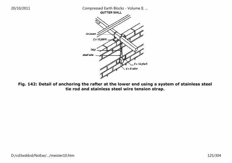
Fig. 142: Detail of anchoring the rafter at the lower end using a system of stainless steel
tie rod and stainless steel wire tension strap.
20/10/2011 Compressed Earth Blocks - Volume II. …
D:/cd3wddvd/NoExe/…/meister10.htm 125/304
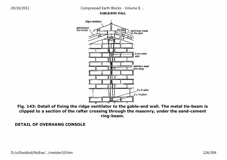
Fig. 143: Detail of fixing the ridge ventilator to the gable-end wall. The metal tie-beam is
clipped to a section of the rafter crossing through the masonry, under the sand-cement
ring-beam.
DETAIL OF OVERHANG CONSOLE
20/10/2011 Compressed Earth Blocks - Volume II. …
D:/cd3wddvd/NoExe/…/meister10.htm 126/304
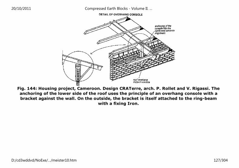
Fig. 144: Housing project, Cameroon. Design CRATerre, arch. P. Rollet and V. Rigassi. The
anchoring of the lower side of the roof uses the principle of an overhang console with a
bracket against the wall. On the outside, the bracket is itself attached to the ring-beam
with a fixing Iron.
20/10/2011 Compressed Earth Blocks - Volume II. …
D:/cd3wddvd/NoExe/…/meister10.htm 127/304
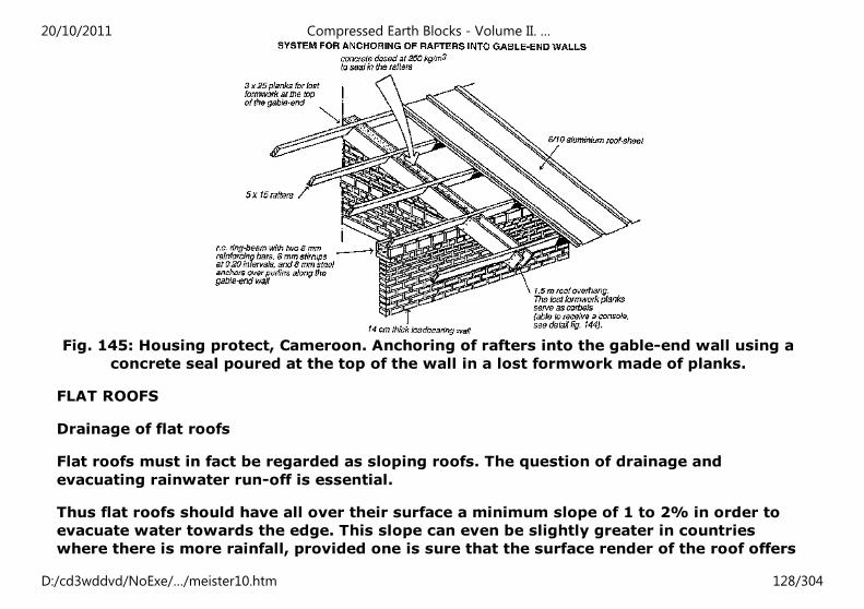
Fig. 145: Housing protect, Cameroon. Anchoring of rafters into the gable-end wall using a
concrete seal poured at the top of the wall in a lost formwork made of planks.
FLAT ROOFS
Drainage of flat roofs
Flat roofs must in fact be regarded as sloping roofs. The question of drainage and
evacuating rainwater run-off is essential.
Thus flat roofs should have all over their surface a minimum slope of 1 to 2% in order to
evacuate water towards the edge. This slope can even be slightly greater in countries
where there is more rainfall, provided one is sure that the surface render of the roof offers
20/10/2011 Compressed Earth Blocks - Volume II. …
D:/cd3wddvd/NoExe/…/meister10.htm 128/304
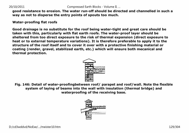
good resistance to erosion. The water run-off should be directed and channelled in such a
way as not to disperse the entry points of spouts too much.
Water-proofing flat roofs
Good drainage is no substitute for the roof being water-tight and great care should be
taken with this, particularly with flat earth roofs. The water-proof layer should be
sheltered from too direct exposure to the risk of thermal expansion (direct exposure to
heat or to external temperature variations). It is therefore preferable to apply it to the
structure of the roof itself and to cover it over with a protective finishing material or
coating (render, gravel, stabilized earth, etc.) which will ensure both mecanical and
thermal protection.
Fig. 146: Detail of water-proofingbetween roof/ parapet and roof/wall. Note the flexible
system of laying of beams into the wall with insulation (thermal bridge) and
waterproofing of the receiving base.
20/10/2011 Compressed Earth Blocks - Volume II. …
D:/cd3wddvd/NoExe/…/meister10.htm 129/304
Fig. 147: Totally water-proof entry and exit points of spout Protection of the top of the
parapet (fired bricks, concrete poured in situ etc.).
Parapets and water-spouts
The water-proof layer should be perfectly and evenly banked up against the parapets,
without any flaws. It is advisable to have a gutter at the base of the parapet to drain the
water towards the rain water spouts or downpipes. These are designed in hard, durable
materials and should evacuate the water well away from the facades, not be located facing
the prevailing wind (water throw-back) nor over an opening. The junction between the
roof, the parapet and the systems of evacuation must be perfectly water-tight.
Finishings
When protecting the walls of a compressed earth block structure is desirable, even
necessary, one can have recourse to various technical solutions suited to a great many
local contexts. But these solutions are alas often badly executed and paradoxically help to
give rise to or aggravate the very problems they are intended to resolve. Choosing a
solution for protecting a surface should above all be suited to the local economy of the
project context as they are still often solutions the costs of which are prohibitive. One
should therefore start by making sure that it really is necessary to protect the wall
surfaces, bearing in mind that the great advantage of the compressed earth block
compared to the sand-cement block is that it offers a greater capacity to resist the direct
or capillary infiltration of rainwater or flowing water. In along-cost housing project, the
render can represent up to 25% of the overall cost of the construction. A compressed
earth block wall with a good bonding pattern and built with high quality mortar binding
together all the elements in all directions and resistant to erosion, is not permeable. One
can therefore manage without a render and ultimately reduce the cost of construction as
well as the amount of cement used. We explain here the areas and conditions for applying
20/10/2011 Compressed Earth Blocks - Volume II. …
D:/cd3wddvd/NoExe/…/meister10.htm 130/304
a surface protection. If, for one reason or another, such protection is needed, than it must
be applied following the guide-linesforapplication which we specify below. Above all, the
protection must remain supple and moisture permeable to avoid the risk of it peeling off
or separating.
CONDITIONS OF APPLICATION
Preparing the support
Removing dust:
The wall to which a render is to be applied must be free of all loose, crumbly or dusty
material. It should be carefully brushed (using a metal brush.)
Moistening:
The wall must not absorb the water contained in the render or it will not set or harden so
well and it will stick less well. The wall must therefore be moistened in order to avoid
capillary suction occurring, but it should not be too wet as a film of water at the surface
would limit the adherence of the render.
When to apply the render
An earth wall must never be rendered before:
- The shrinkage of the masonry during drying out has stabilized and the water and
moisture has completely dried out. This can take several weeks.
- The wall has been allowed to settle. This means waiting for all structural work to be
complete, including all the loads of floors and roofs.
20/10/2011 Compressed Earth Blocks - Volume II. …
D:/cd3wddvd/NoExe/…/meister10.htm 131/304
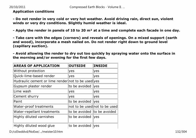
Application conditions
- Do not render in very cold or very hot weather. Avoid driving rain, direct sun, violent
winds or very dry conditions. Slightly humid weather is ideal.
- Apply the render in panels of 10 to 20 m² at a time and complete each facade in one day.
- Take care with the edges (corners) and reveals of openings. On a mixed support (earth
and wood), incorporate a mesh nailed on. Do not render right down to ground level
(capillary suction).
- Avoid allowing the render to dry out too quickly by spraying water onto the surface in
the morning and/or evening for the first few days.
AREAS OF APPLICATION OUTSIDE INSIDE
Without protection yes yes
Quick-lime-based render yes yes
Hydraulic cement or lime render not to be used yes
Gypsum plaster render to be avoided yes
Lime wash yes yes
Cement shurry yes yes
Paint to be avoided yes
Water-proof treatments not to be used not to be used
Water-repellant treatments to be avoided to be avoided
Highly diluted varnishes to be avoided yes
Highly diluted wood glue to be avoided yes
20/10/2011 Compressed Earth Blocks - Volume II. …
D:/cd3wddvd/NoExe/…/meister10.htm 132/304
Fig. 152: Various areas of application for renders, distempers paints and impregnations on
outside or inside walls.
RENDERS
Renders are generally applied in three layers, but sometimes two layers suffice.
The first layer, known as a rough coat or "primer", is made up of a fairly fluid mortar
which is thrown with force onto the support using a trowel. Between 3 and 5 mm thick,
the surface of this layer is rough so that the next layer will stick more easily.
The second layer, known as the "coating" or the "body of the render" is applied a few days
after the primer (minimum 2 days) in one or two passes. This layer is 8 to 20 mm thick
and is carefully smoothed using a ruler; it should. display no cracks.
The third layer, known as the "finishing render", completes the rendering process and fills
any shrinkage cracks which might have appeared in the coating. It is applied when the
coating has completely dried out. It is only a few mm thick and it can be finished with a
plasterer's hawk without applying too much pressure.
Cement or hydraulic lime render
A render may consist of hydraulic lime and cement if low dosages are used. One should
limit the composition to something in the order of 1 volume of binding agent to 5 to 10
volumes of sand. Renders which are too stiff should not be used on the outside as they
often fail to adhere well to earth walls.
Gypsum plaster
20/10/2011 Compressed Earth Blocks - Volume II. …
D:/cd3wddvd/NoExe/…/meister10.htm 133/304
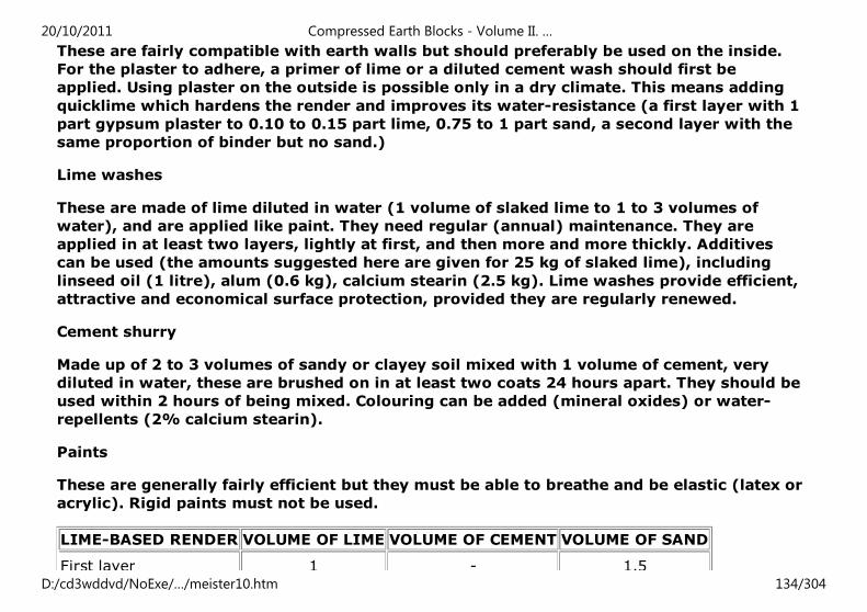
These are fairly compatible with earth walls but should preferably be used on the inside.
For the plaster to adhere, a primer of lime or a diluted cement wash should first be
applied. Using plaster on the outside is possible only in a dry climate. This means adding
quicklime which hardens the render and improves its water-resistance (a first layer with 1
part gypsum plaster to 0.10 to 0.15 part lime, 0.75 to 1 part sand, a second layer with the
same proportion of binder but no sand.)
Lime washes
These are made of lime diluted in water (1 volume of slaked lime to 1 to 3 volumes of
water), and are applied like paint. They need regular (annual) maintenance. They are
applied in at least two layers, lightly at first, and then more and more thickly. Additives
can be used (the amounts suggested here are given for 25 kg of slaked lime), including
linseed oil (1 litre), alum (0.6 kg), calcium stearin (2.5 kg). Lime washes provide efficient,
attractive and economical surface protection, provided they are regularly renewed.
Cement shurry
Made up of 2 to 3 volumes of sandy or clayey soil mixed with 1 volume of cement, very
diluted in water, these are brushed on in at least two coats 24 hours apart. They should be
used within 2 hours of being mixed. Colouring can be added (mineral oxides) or water-
repellents (2% calcium stearin).
Paints
These are generally fairly efficient but they must be able to breathe and be elastic (latex or
acrylic). Rigid paints must not be used.
LIME-BASED RENDER VOLUME OF LIME VOLUME OF CEMENT VOLUME OF SAND
First layer 1 - 1.5
20/10/2011 Compressed Earth Blocks - Volume II. …
D:/cd3wddvd/NoExe/…/meister10.htm 134/304
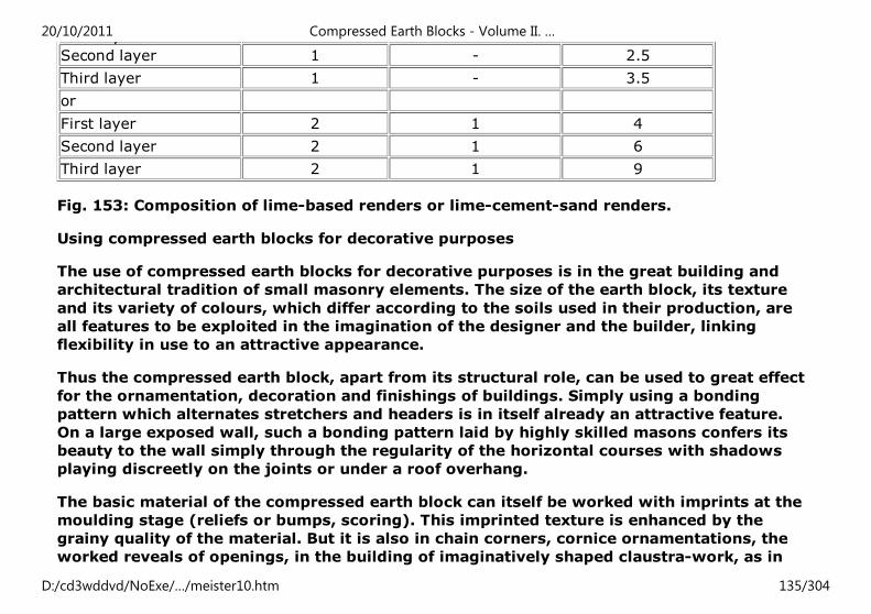
First layer 1 - 1.5
Second layer 1 - 2.5
Third layer 1 - 3.5
or
First layer 2 1 4
Second layer 2 1 6
Third layer 2 1 9
Fig. 153: Composition of lime-based renders or lime-cement-sand renders.
Using compressed earth blocks for decorative purposes
The use of compressed earth blocks for decorative purposes is in the great building and
architectural tradition of small masonry elements. The size of the earth block, its texture
and its variety of colours, which differ according to the soils used in their production, are
all features to be exploited in the imagination of the designer and the builder, linking
flexibility in use to an attractive appearance.
Thus the compressed earth block, apart from its structural role, can be used to great effect
for the ornamentation, decoration and finishings of buildings. Simply using a bonding
pattern which alternates stretchers and headers is in itself already an attractive feature.
On a large exposed wall, such a bonding pattern laid by highly skilled masons confers its
beauty to the wall simply through the regularity of the horizontal courses with shadows
playing discreetly on the joints or under a roof overhang.
The basic material of the compressed earth block can itself be worked with imprints at the
moulding stage (reliefs or bumps, scoring). This imprinted texture is enhanced by the
grainy quality of the material. But it is also in chain corners, cornice ornamentations, the
worked reveals of openings, in the building of imaginatively shaped claustra-work, as in
20/10/2011 Compressed Earth Blocks - Volume II. …
D:/cd3wddvd/NoExe/…/meister10.htm 135/304
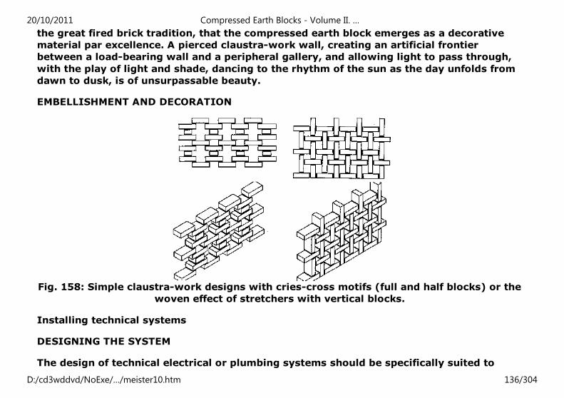
the great fired brick tradition, that the compressed earth block emerges as a decorative
material par excellence. A pierced claustra-work wall, creating an artificial frontier
between a load-bearing wall and a peripheral gallery, and allowing light to pass through,
with the play of light and shade, dancing to the rhythm of the sun as the day unfolds from
dawn to dusk, is of unsurpassable beauty.
EMBELLISHMENT AND DECORATION
Fig. 158: Simple claustra-work designs with cries-cross motifs (full and half blocks) or the
woven effect of stretchers with vertical blocks.
Installing technical systems
DESIGNING THE SYSTEM
The design of technical electrical or plumbing systems should be specifically suited to
20/10/2011 Compressed Earth Blocks - Volume II. …
D:/cd3wddvd/NoExe/…/meister10.htm 136/304
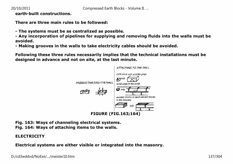
earth-built constructions.
There are three main rules to be followed:
- The systems must be as centralized as possible.
- Any incorporation of pipelines for supplying and removing fluids into the walls must be
avoided.
- Making grooves in the walls to take electricity cables should be avoided.
Following these three rules necessarily implies that the technical installations must be
designed in advance and not on site, at the last minute.
FIGURE (FIG.163;164)
Fig. 163: Ways of channeling electrical systems.
Fig. 164: Ways of attaching items to the walls.
ELECTRICITY
Electrical systems are either visible or integrated into the masonry.
20/10/2011 Compressed Earth Blocks - Volume II. …
D:/cd3wddvd/NoExe/…/meister10.htm 137/304
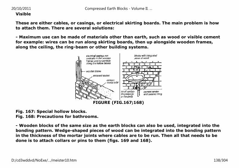
Visible
These are either cables, or casings, or electrical skirting boards. The main problem is how
to attach them. There are several solutions:
- Maximum use can be made of materials other than earth, such as wood or visible cement
for example: wires can be run along skirting boards, then up alongside wooden frames,
along the ceiling, the ring-beam or other building systems.
FIGURE (FIG.167;168)
Fig. 167: Special hollow blocks.
Fig. 168: Precautions for bathrooms.
- Wooden blocks of the same size as the earth blocks can also be used, integrated into the
bonding pattern. Wedge-shaped pieces of wood can be integrated into the bonding pattern
in the thickness of the mortar joints where cables are to be run. Then all that needs to be
done is to attach collars or pins to them (figs. 169 and 168).
20/10/2011 Compressed Earth Blocks - Volume II. …
D:/cd3wddvd/NoExe/…/meister10.htm 138/304
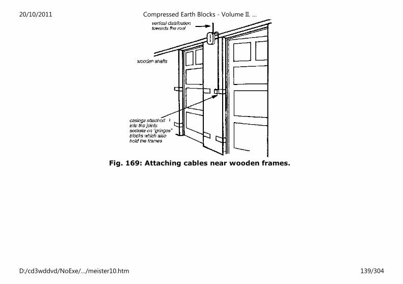
Fig. 169: Attaching cables near wooden frames.
20/10/2011 Compressed Earth Blocks - Volume II. …
D:/cd3wddvd/NoExe/…/meister10.htm 139/304
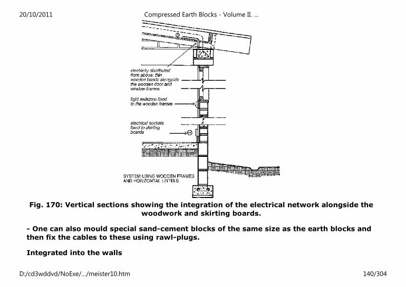
Fig. 170: Vertical sections showing the integration of the electrical network alongside the
woodwork and skirting boards.
- One can also mould special sand-cement blocks of the same size as the earth blocks and
then fix the cables to these using rawl-plugs.
Integrated into the walls
20/10/2011 Compressed Earth Blocks - Volume II. …
D:/cd3wddvd/NoExe/…/meister10.htm 140/304
The cables are protected by casings which are integrated into the thickness of the walls
during construction and the junction boxes are integrated into the surface of the walls.
The casings can be run horizontally in special hollow blocks or behind grooved skirting
boards. Gaps can also be left in the ring-beam and these then covered up using a joint-
cover on the facade. Maximum use must be made of wooden frames to run casings
vertically. The integration of plug sockets, light switches, and junction boxes can be done
by cutting into the blocks and then fixing them with mortar or using special blocks
moulded in sand-cement, incorporating the sockets and tubing to connect the cables (figs.
166 and 167).
PLUMBING
Water supply
The pipework should be integrated into the thickness of the floor to the maximum extent
possible and where pipes pass through the walls, a protective pipe-sleeve should be used.
Any other pipes, horizontal or vertical, should remain visible and the same principle as for
electrical cables can be used for attaching them to the surface of the walls.
Water removal
The principle is the same as for water supply but inspection hatches must be included with
very long pipes, and where there are bends or junctions.
Bathrooms
The walls close to bathroom fittings (handbasin, shower, bath) must without fail be
rendered or tiled. A floor syphon should also be fitted to make it easier to clean the floor
and to evacuate water in the
event of a leak. Good ventilation is also recommended to avoid condensation.
20/10/2011 Compressed Earth Blocks - Volume II. …
D:/cd3wddvd/NoExe/…/meister10.htm 141/304
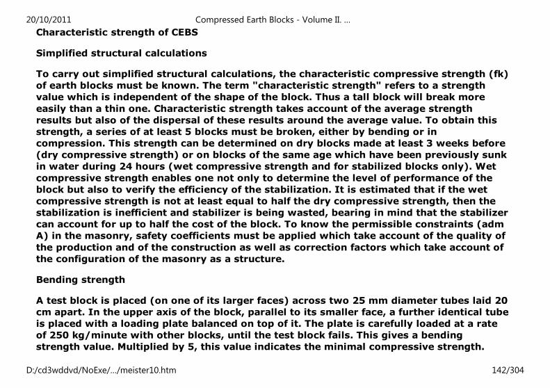
Characteristic strength of CEBS
Simplified structural calculations
To carry out simplified structural calculations, the characteristic compressive strength (fk)
of earth blocks must be known. The term "characteristic strength" refers to a strength
value which is independent of the shape of the block. Thus a tall block will break more
easily than a thin one. Characteristic strength takes account of the average strength
results but also of the dispersal of these results around the average value. To obtain this
strength, a series of at least 5 blocks must be broken, either by bending or in
compression. This strength can be determined on dry blocks made at least 3 weeks before
(dry compressive strength) or on blocks of the same age which have been previously sunk
in water during 24 hours (wet compressive strength and for stabilized blocks only). Wet
compressive strength enables one not only to determine the level of performance of the
block but also to verify the efficiency of the stabilization. It is estimated that if the wet
compressive strength is not at least equal to half the dry compressive strength, then the
stabilization is inefficient and stabilizer is being wasted, bearing in mind that the stabilizer
can account for up to half the cost of the block. To know the permissible constraints (adm
A) in the masonry, safety coefficients must be applied which take account of the quality of
the production and of the construction as well as correction factors which take account of
the configuration of the masonry as a structure.
Bending strength
A test block is placed (on one of its larger faces) across two 25 mm diameter tubes laid 20
cm apart. In the upper axis of the block, parallel to its smaller face, a further identical tube
is placed with a loading plate balanced on top of it. The plate is carefully loaded at a rate
of 250 kg/minute with other blocks, until the test block fails. This gives a bending
strength value. Multiplied by 5, this value indicates the minimal compressive strength.
20/10/2011 Compressed Earth Blocks - Volume II. …
D:/cd3wddvd/NoExe/…/meister10.htm 142/304
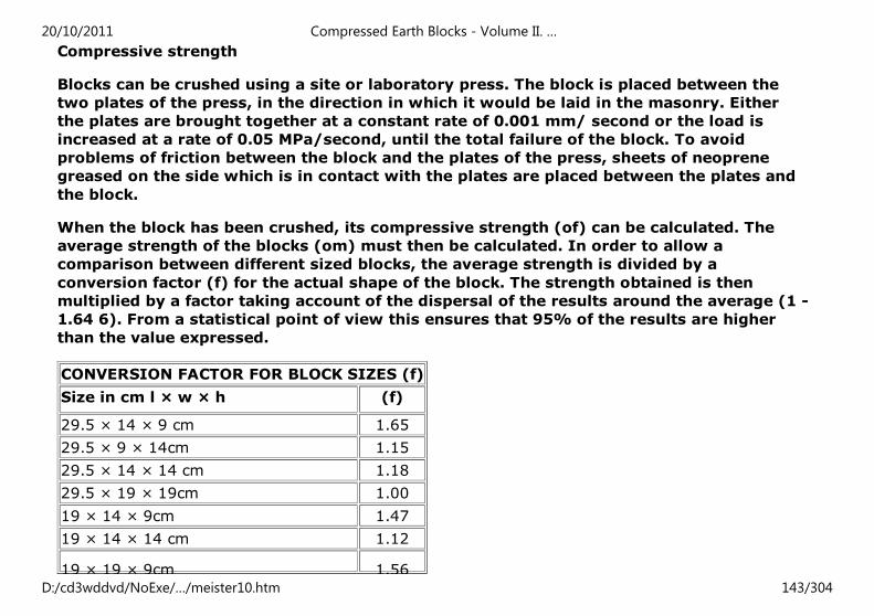
Compressive strength
Blocks can be crushed using a site or laboratory press. The block is placed between the
two plates of the press, in the direction in which it would be laid in the masonry. Either
the plates are brought together at a constant rate of 0.001 mm/ second or the load is
increased at a rate of 0.05 MPa/second, until the total failure of the block. To avoid
problems of friction between the block and the plates of the press, sheets of neoprene
greased on the side which is in contact with the plates are placed between the plates and
the block.
When the block has been crushed, its compressive strength (of) can be calculated. The
average strength of the blocks (om) must then be calculated. In order to allow a
comparison between different sized blocks, the average strength is divided by a
conversion factor (f) for the actual shape of the block. The strength obtained is then
multiplied by a factor taking account of the dispersal of the results around the average (1 -
1.64 6). From a statistical point of view this ensures that 95% of the results are higher
than the value expressed.
CONVERSION FACTOR FOR BLOCK SIZES (f)
Size in cm l × w × h (f)
29.5 × 14 × 9 cm 1.65
29.5 × 9 × 14cm 1.15
29.5 × 14 × 14 cm 1.18
29.5 × 19 × 19cm 1.00
19 × 14 × 9cm 1.47
19 × 14 × 14 cm 1.12
19 × 19 × 9cm 1.56
20/10/2011 Compressed Earth Blocks - Volume II. …
D:/cd3wddvd/NoExe/…/meister10.htm 143/304
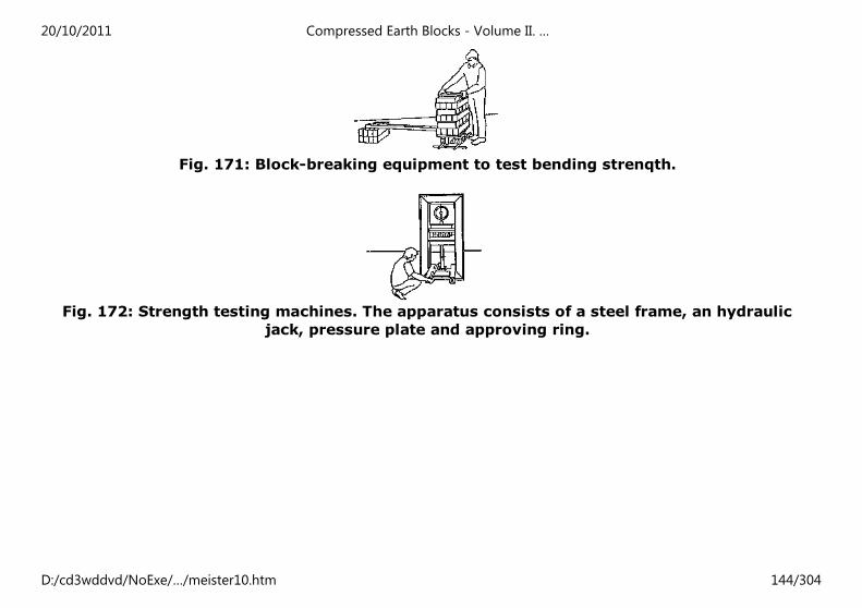
Fig. 171: Block-breaking equipment to test bending strenqth.
Fig. 172: Strength testing machines. The apparatus consists of a steel frame, an hydraulic
jack, pressure plate and approving ring.
20/10/2011 Compressed Earth Blocks - Volume II. …
D:/cd3wddvd/NoExe/…/meister10.htm 144/304
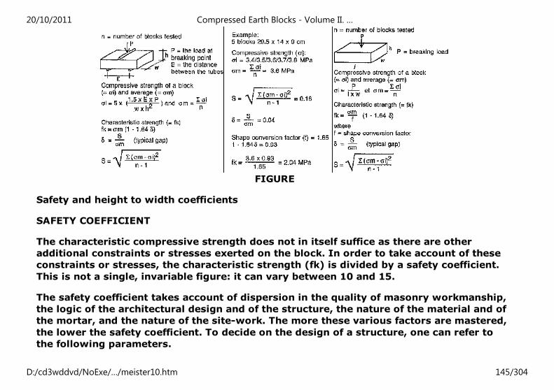
FIGURE
Safety and height to width coefficients
SAFETY COEFFICIENT
The characteristic compressive strength does not in itself suffice as there are other
additional constraints or stresses exerted on the block. In order to take account of these
constraints or stresses, the characteristic strength (fk) is divided by a safety coefficient.
This is not a single, invariable figure: it can vary between 10 and 15.
The safety coefficient takes account of dispersion in the quality of masonry workmanship,
the logic of the architectural design and of the structure, the nature of the material and of
the mortar, and the nature of the site-work. The more these various factors are mastered,
the lower the safety coefficient. To decide on the design of a structure, one can refer to
the following parameters.
20/10/2011 Compressed Earth Blocks - Volume II. …
D:/cd3wddvd/NoExe/…/meister10.htm 145/304
Structural concept
An even distribution of loads and of openings spreads the loads well, avoids areas of
concentration and allows the masonry to work at lower rates.
HEIGHT TO WIDTH (λλλλ)
A thin, high wall is vulnerable to the risk of buckling, even if the blocks are strong. The
wall should therefore have a maximum height to width value of 20.
λλλλ = hef / tef < 20
λλλλ = height to width
hef = effective height
tef = effective thickness
The effective height of a wall (hef) depends on the type of integration used between the
wall, the foundations and the floors. The table on the right (fig. 173) shows that a
perimeter wall, considered to be freestanding, has twice the height to width value of a
wall of the same height on which rests a concrete floor. For effective thickness (tef), as
we can see a wall 14 cm thick with 29.5 cm buttresses every 1,5 m has a height to width
value approximately 1 .5 times lower than that of an identical 14 cm wall without
buttresses.
Building details
A good footing and a good roof protects the building against bad weather and
deterioration, making its stronger.
Climatic conditions
20/10/2011 Compressed Earth Blocks - Volume II. …
D:/cd3wddvd/NoExe/…/meister10.htm 146/304
Depending on the climatic conditions, the building will be more or less exposed to bad
weather conditions and the quality requirements of the blocks will need to be more or less
high.
Types of building
There are two main types of building.
Single-storey buildings: minimal load stresses, little aerodynamic effect, little surface area
exposed to bad weather conditions.
Multi-storey buildings: significant load stresses, aerodynamic effects due to high exposure
to wind, large surface area exposed to bad weather conditions.
Intended use of the buildings
Individual private use such as a house: the quality of workmanship takes account of the
maintenance factor which will vary depending on whether it is rented accommodation
(limited investment) or owned property (investment guaranteed).
Public use: collective facilities. Particular care should be taken with the quality of
workmanship as these buildings have a social role to play and serve as examples. Their
maintenance must be well ensured.
Protecting the building
An earth building should be able to resist the effect of water. The quality of the materials
is important but the design of the building is even more so. One should bear in mind, in
order of priority:
- a special design for the building with high footings and large roof overhangs.
20/10/2011 Compressed Earth Blocks - Volume II. …
D:/cd3wddvd/NoExe/…/meister10.htm 147/304
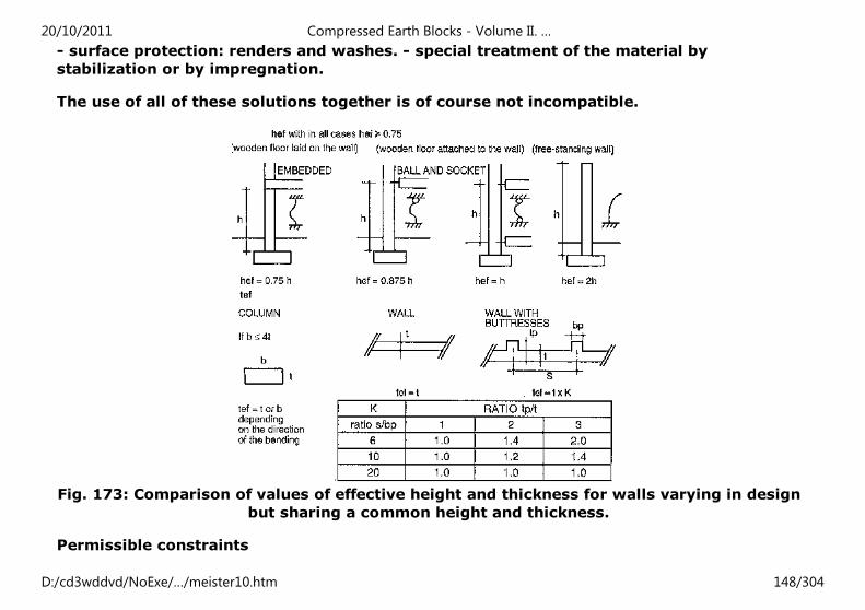
- surface protection: renders and washes. - special treatment of the material by
stabilization or by impregnation.
The use of all of these solutions together is of course not incompatible.
Fig. 173: Comparison of values of effective height and thickness for walls varying in design
but sharing a common height and thickness.
Permissible constraints
20/10/2011 Compressed Earth Blocks - Volume II. …
D:/cd3wddvd/NoExe/…/meister10.htm 148/304
Small section walls (W < 0.3 m²)
For walls with a section less than 0.3 m², take the characteristic strength, multiply it by a
correction factor for the height to width value (c), divide by the safety coefficient and
multiply by a reduction factor for the small section. This applies for example to a pier wall
between two openings.
The reduction factor is ( ) where ΩΩΩΩ= surface area of the section in m².
Walls with low height to width values (λλλλ < 6)
Here, the permissible load is obtained by dividing the characteristic compressive strength
of the blocks (fk) by the safety coefficient which can vary between 10 and 15. These are
fairly severe conditions as this is a simplified calculation and because several factors are
often neglected: the quality of the mortar, the quality of the bonding, for example. Greater
mastery of these factors and a detailed calculation of the downward loads enables this
safety coefficient to be lowered. This permissible constraint must therefore be regarded as
a rapid calculation right at the initial pre-project planning stage. In many cases this
anticipated knowledge of the constraints will suffice except in extreme situations (regions
subject to seismic risk or to cyclones for example).
Walls with high height to width values (6 < λλλλ < 20)
For walls with high height to width values, the permissible constraint is calculated in the
same way as above and the result multiplied by an additional correction factor (c) which
takes account of the height to width value of the wall and of the waythe loads are applied.
A wall subjected to excentric loads will buckle faster than a wall loaded on its axis.
Excentricity can have two sources:
20/10/2011 Compressed Earth Blocks - Volume II. …
D:/cd3wddvd/NoExe/…/meister10.htm 149/304
- loads applied out of true with the axis e.g. a cantilever floor attached to the wall
- horizontal loads (e.g. wind is turned into vertical loads out of alignment)
FIGURE
Excentricity is expressed by the factor m =6e/tef which takes account of the position of
the vertical loads vis--vis the central third of the wall.
The examples (fig. 174 to 176) illustrate how permissible constraints vary with the
thickness of the wall and the section of the wall: a wall using a header bonding pattern
(30 cm thick) can support 4.5 times the load of a pier wall using a stretcher bonding
pattern (14 cm thick).
Fig. 174: Example of a calculation of constraints for a wall with a low height to width
value.
20/10/2011 Compressed Earth Blocks - Volume II. …
D:/cd3wddvd/NoExe/…/meister10.htm 150/304
Fig. 175:Example of a calculation of permissible load for a wall with high height to width
value.
20/10/2011 Compressed Earth Blocks - Volume II. …
D:/cd3wddvd/NoExe/…/meister10.htm 151/304
Fig. 176: Example of a calculation of permissible loads for a small section wall.
FIGURE
EXAMPLE OF SIMPLIFIED CALCULATION
For single-storey buildings, the downward load is approximately 0.10 MPa, and for two-
storey buildings 0.15 MPa. Let us take the example of fairly unfavourable conditions and
20/10/2011 Compressed Earth Blocks - Volume II. …
D:/cd3wddvd/NoExe/…/meister10.htm 152/304
see what kind of block could be used for a two-storey building. This unfavourable case is
that of a pier wall between two openings, the height of which between floors is 2.40 m
(see fig. 176).
The table on the right (fig. 177) shows the necessary characteristic strength of the blocks
taking various configurations of masonry and for various safety coefficients, assuming
excentric loads (m = 1). In the most unfavourable case, the characteristic strength (fk)
needed is 4 MPa, which corresponds to blocks with a compressive strength on crushing of
7.5 MPa which must be regarded as very severe. On the other hand, as can be seen, a
simple modification of the masonry configuration helps to considerably lower the strength
needed and very quickly this becomes reasonable, even with very high safety coefficients.
Fig. 177: Relationship between characteristic strength and masonry configuration.
To give some indications, we have drawn up here a table of the typical values which can
be expected of a compressed earth block. This data refers to stabilized blocks. If the
blocks are not stabilized, the wet compressive strength drops until it is virtually nil.
Similarly, the tensile, bending and shearing strengths drop slightly. Remember that these
simplified calculation guide-lines apply only to the pre-project stage and that they cannot
be applied to extreme situations (earthquake areas or typhoon risk). In these cases,
reinforced or strengthened masonry solutions requiring specific calculations will need to
20/10/2011 Compressed Earth Blocks - Volume II. …
D:/cd3wddvd/NoExe/…/meister10.htm 153/304
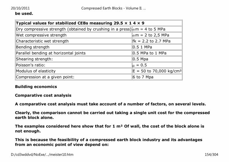
be used.
Typical values for stabilized CEBs measuring 29.5 × 1 4 × 9
Dry compressive strength (obtained by crushing in a press) σm = 4 to 5 MPa
Wet compressive strength σm = 2 to 2,5 MPa
Characteristic wet strength fk = 2.2 to 2.7 MPa
Bending strength 0.5 1 MPa
Parallel bending at horizontal joints 0.5 MPa to 1 MPa
Shearing strength: 0.5 Mpa
Poisson's ratio: µ = 0.5
Modulus of elasticity E = 50 to 70,000 kg/cm²
Compression at a given point: 6 to 7 Mpa
Building economics
Comparative cost analysis
A comparative cost analysis must take account of a number of factors, on several levels.
Clearly, the comparison cannot be carried out taking a single unit cost for the compressed
earth block alone.
The examples considered here show that for 1 m² Of wall, the cost of the block alone is
not enough.
This is because the feasibility of a compressed earth block industry and its advantages
from an economic point of view depend on:
20/10/2011 Compressed Earth Blocks - Volume II. …
D:/cd3wddvd/NoExe/…/meister10.htm 154/304
- the cost of the raw materials (quarrying, transport);
- the cost of the blocks (production);
- the costs of labour (brick-makers, builders, etc.);
- the type of production and construction organisation (self-help building, hiring skilled
labour, using a building contractor);
- the type of building system used for the structures;
- the quality of finishings.
The examples we take compare 1 m² of finished wall, one in stabilized compressed earth
blocks and the other in sand-cement blocks with a reinforced concrete supporting
framework, and this in various contexts.
Analysis of the results clearly shows that it would be difficult and totally arbitrary to draw
universally applicable conclusions. When all the factors are taken into account, a solution
selected as viable in one context, may not be so in another.
Although interesting, this analysis cannot be regarded as complete if it fails to take
account of the final objective, which is to build a complete building. A cost comparison of
the whole process must therefore be carried out taking account of the production process
of materials and the construction process of the structures in a specific socio-economic
context.
20/10/2011 Compressed Earth Blocks - Volume II. …
D:/cd3wddvd/NoExe/…/meister10.htm 155/304
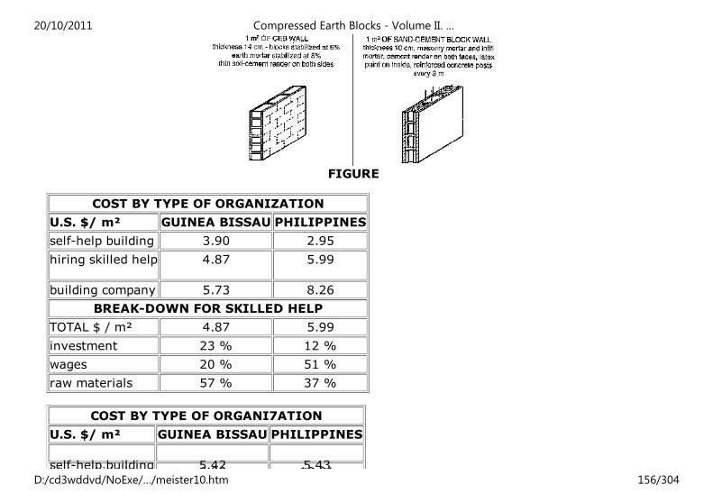
FIGURE
COST BY TYPE OF ORGANIZATION
U.S. $/ m² GUINEA BISSAU PHILIPPINES
self-help building 3.90 2.95
hiring skilled help 4.87 5.99
building company 5.73 8.26
BREAK-DOWN FOR SKILLED HELP
TOTAL $ / m² 4.87 5.99
investment 23 % 12 %
wages 20 % 51 %
raw materials 57 % 37 %
COST BY TYPE OF ORGANI7ATION
U.S. $/ m² GUINEA BISSAU PHILIPPINES
self-help building 5.42 5.43hiring skilled 6.88 10.01
20/10/2011 Compressed Earth Blocks - Volume II. …
D:/cd3wddvd/NoExe/…/meister10.htm 156/304
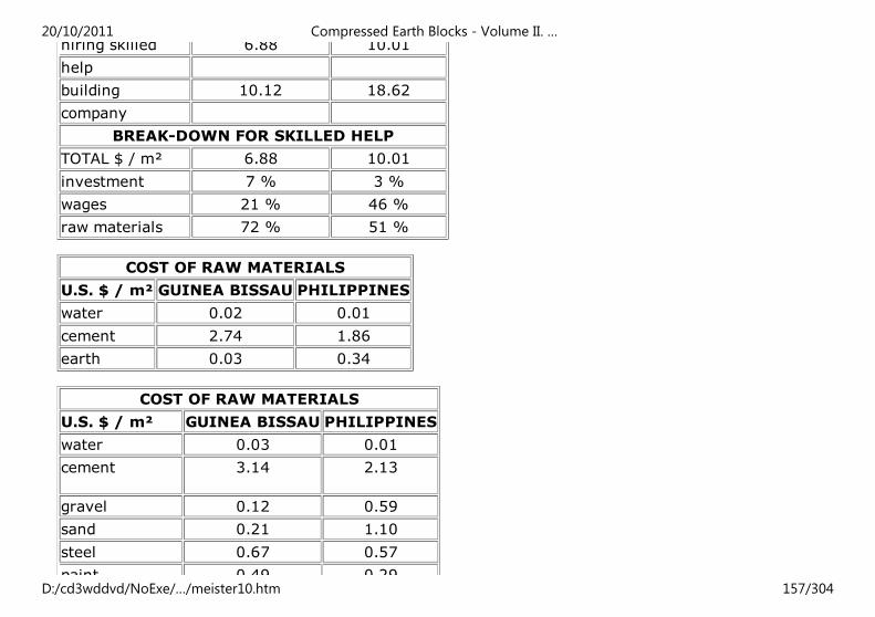
hiring skilled 6.88 10.01
help
building 10.12 18.62
company
BREAK-DOWN FOR SKILLED HELP
TOTAL $ / m² 6.88 10.01
investment 7 % 3 %
wages 21 % 46 %
raw materials 72 % 51 %
COST OF RAW MATERIALS
U.S. $ / m² GUINEA BISSAU PHILIPPINES
water 0.02 0.01
cement 2.74 1.86
earth 0.03 0.34
COST OF RAW MATERIALS
U.S. $ / m² GUINEA BISSAU PHILIPPINES
water 0.03 0.01
cement 3.14 2.13
gravel 0.12 0.59
sand 0.21 1.10
steel 0.67 0.57
paint 0,49 0.29
20/10/2011 Compressed Earth Blocks - Volume II. …
D:/cd3wddvd/NoExe/…/meister10.htm 157/304
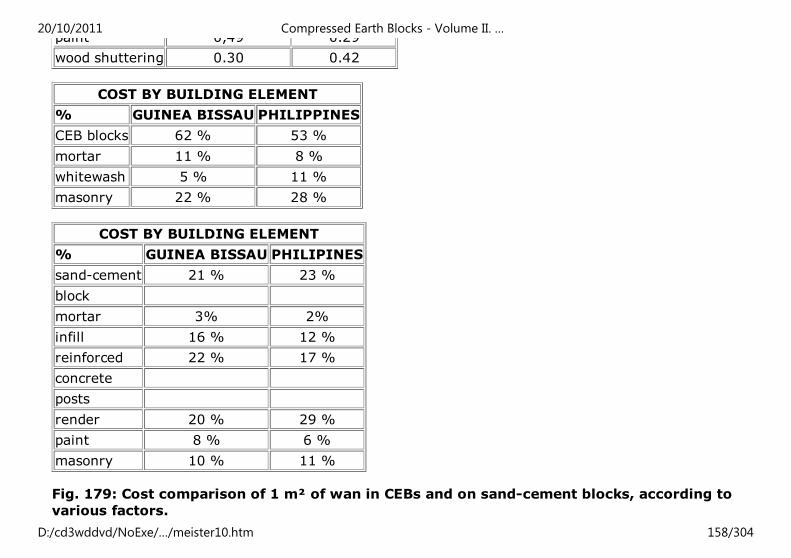
paint 0,49 0.29
wood shuttering 0.30 0.42
COST BY BUILDING ELEMENT
% GUINEA BISSAU PHILIPPINES
CEB blocks 62 % 53 %
mortar 11 % 8 %
whitewash 5 % 11 %
masonry 22 % 28 %
COST BY BUILDING ELEMENT
% GUINEA BISSAU PHILIPINES
sand-cement 21 % 23 %
block
mortar 3% 2%
infill 16 % 12 %
reinforced 22 % 17 %
concrete
posts
render 20 % 29 %
paint 8 % 6 %
masonry 10 % 11 %
Fig. 179: Cost comparison of 1 m² of wan in CEBs and on sand-cement blocks, according to
various factors.
20/10/2011 Compressed Earth Blocks - Volume II. …
D:/cd3wddvd/NoExe/…/meister10.htm 158/304
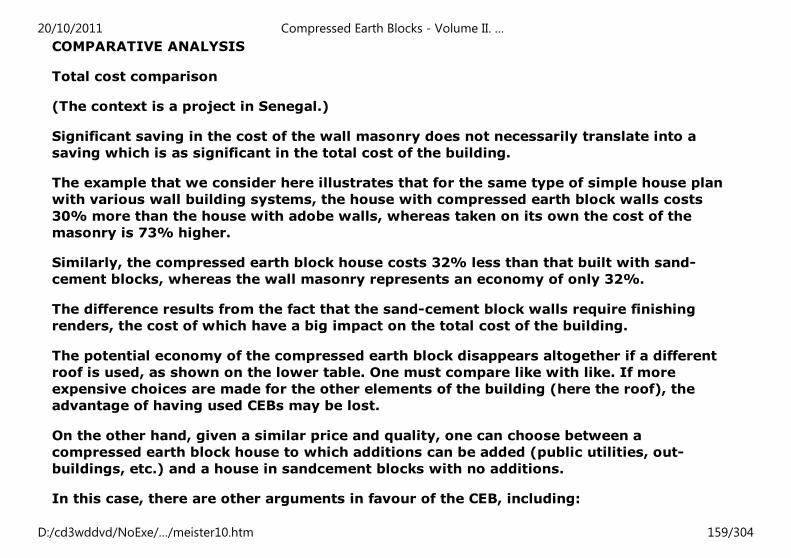
COMPARATIVE ANALYSIS
Total cost comparison
(The context is a project in Senegal.)
Significant saving in the cost of the wall masonry does not necessarily translate into a
saving which is as significant in the total cost of the building.
The example that we consider here illustrates that for the same type of simple house plan
with various wall building systems, the house with compressed earth block walls costs
30% more than the house with adobe walls, whereas taken on its own the cost of the
masonry is 73% higher.
Similarly, the compressed earth block house costs 32% less than that built with sand-
cement blocks, whereas the wall masonry represents an economy of only 32%.
The difference results from the fact that the sand-cement block walls require finishing
renders, the cost of which have a big impact on the total cost of the building.
The potential economy of the compressed earth block disappears altogether if a different
roof is used, as shown on the lower table. One must compare like with like. If more
expensive choices are made for the other elements of the building (here the roof), the
advantage of having used CEBs may be lost.
On the other hand, given a similar price and quality, one can choose between a
compressed earth block house to which additions can be added (public utilities, out-
buildings, etc.) and a house in sandcement blocks with no additions.
In this case, there are other arguments in favour of the CEB, including:
20/10/2011 Compressed Earth Blocks - Volume II. …
D:/cd3wddvd/NoExe/…/meister10.htm 159/304
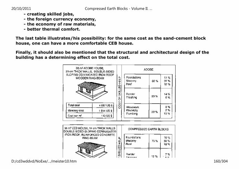
- creating skilled jobs,
- the foreign currency economy,
- the economy of raw materials,
- better thermal comfort.
The last table illustrates/his possibility: for the same cost as the sand-cement block
house, one can have a more comfortable CEB house.
Finally, it should also be mentioned that the structural and architectural design of the
building has a determining effect on the total cost.
20/10/2011 Compressed Earth Blocks - Volume II. …
D:/cd3wddvd/NoExe/…/meister10.htm 160/304
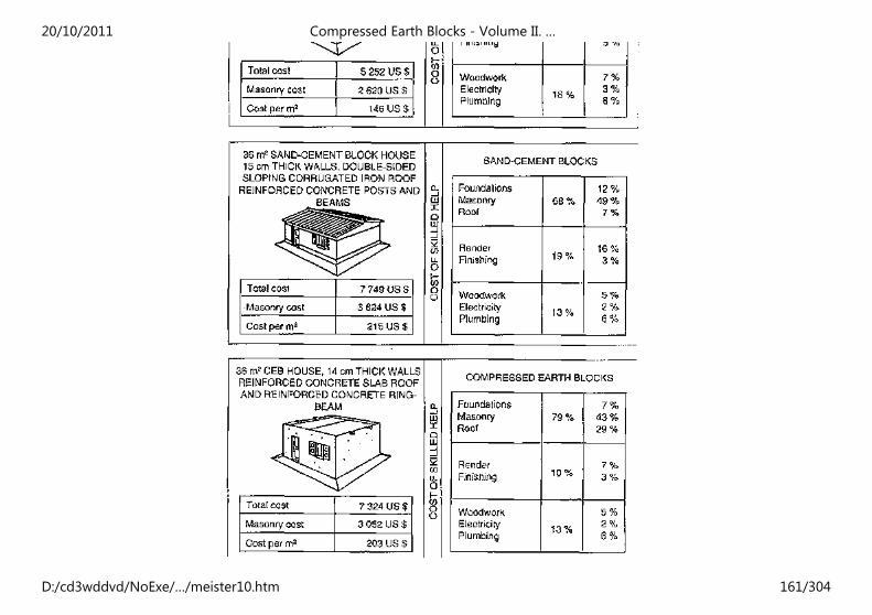
20/10/2011 Compressed Earth Blocks - Volume II. …
D:/cd3wddvd/NoExe/…/meister10.htm 161/304
FIGURE Fig. 180: Comparison of total costs of similar buildings for a project in Senegal.
Home"" """"> ar.cn.de.en.es.fr.id.it.ph.po.ru.sw
Compressed Earth Blocks - Volume II. Manual of design and
construction (GTZ, 1995, 148 p.)
Architecture
Architectural achievements or projects
Architecture for housing
Architecture for public buildings
Compressed Earth Blocks - Volume II. Manual of design and construction (GTZ, 1995, 148
p.)
Architecture
Architectural achievements or projects
A contemporary architecture
The second part of this book on building with compressed earth blocks seeks to show not
only that the genuinely modern way in which this material is used and its diversity are
self-evident, but also the quality of the architectural achievements realized during the
1980's.
20/10/2011 Compressed Earth Blocks - Volume II. …
D:/cd3wddvd/NoExe/…/meister10.htm 162/304
The last ten years have been propitious for a significant development of building with
earth in many countries. The compressed earth block is now recognized as a building
material rich in technical, architectural and - not least - economic potential. Designers and
builders place it high on their list of the range of materials available on the international
building market and more and more compressed earth block building production and
distribution industries are being set up.
Pilot and experimental projects linked to training have provided privileged situations in
which exemplary progress in the use of this material has been made and enabled the
genesis of a genuine architectural heritage founded on the blossoming of a body of
knowledge to emerge. This progress has generated social and economic spin-offs through
the many jobs which have been created in the production and construction industries set
up.
The evidence of a new know-how
The compressed earth block, which can be used only through the setting up of a
production industry, requires specific knowledge and skills at each stage of its production
and use in building, from soil identification at the point of extraction to the completion of
built structures. Along this production chain comes first the quarryman, followed by the
brickmaker, the architect, the builder bricklayer, and the contractor, each of whom is
aware of the potentials and limitations of the material and each of whom develops his own
skills in order to fully exploit the former or to compensate for the latter. Building with
earth blocks is in effect a real training ground closely linking the building logic of the
material itself, with the architectural and the building culture of the architect and of the
builder.
The selected project monographs which we present paint an overall picture of
contemporary architectural achievements. They evoke both the diversity of the register of
20/10/2011 Compressed Earth Blocks - Volume II. …
D:/cd3wddvd/NoExe/…/meister10.htm 163/304
architectural applications in the field of housing and also the great richness of building
solutions applied. May their role as examples boost the confidence of future builders and
fuel their desire to use this material for the realization of housing, schools, colleges or
health centres better suited to the needs and means of the societies they serve.
Architecture for housing
The earth block at the service of mass low-cost housing
Located in the Comoro archipelago, in the straits of Mozambique, between Madagascar and
East Africa the small island of Mayotte is a French Overseas territory which retains its
links with France at the choice of the local population. When the French government
decided to respond to the expectations of the population with regard to improving housing
and public facilities, it deliberately resolved, as a matter of policy, to launch a
development impetus based on the use of local resources. In order to avoid the risk of an
outward-looking economy based on the importation of building materials, the local
decision-makers and elected representatives opted for the use of the mineral deposits to
be found on the island. A vast plan for the identification of these resources was to enable a
Compressed Earth Block industry to be set up, an industry which was to prove to be the
historical lever in the development of the island thanks to the economic activity which the
building sector generated.
20/10/2011 Compressed Earth Blocks - Volume II. …
D:/cd3wddvd/NoExe/…/meister10.htm 164/304
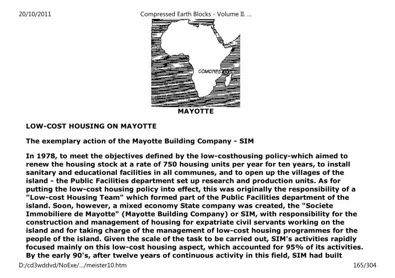
MAYOTTE
LOW-COST HOUSING ON MAYOTTE
The exemplary action of the Mayotte Building Company - SIM
In 1978, to meet the objectives defined by the low-costhousing policy-which aimed to
renew the housing stock at a rate of 750 housing units per year for ten years, to install
sanitary and educational facilities in all communes, and to open up the villages of the
island - the Public Facilities department set up research and production units. As for
putting the low-cost housing policy into effect, this was originally the responsibility of a
"Low-cost Housing Team" which formed part of the Public Facilities department of the
island. Soon, however, a mixed economy State company was created, the "Societe
Immobiliere de Mayotte" (Mayotte Building Company) or SIM, with responsibility for the
construction and management of housing for expatriate civil servants working on the
island and for taking charge of the management of low-cost housing programmes for the
people of the island. Given the scale of the task to be carried out, SIM's activities rapidly
focused mainly on this low-cost housing aspect, which accounted for 95% of its activities.
By the early 90's, after twelve years of continuous activity in this field, SIM had built
20/10/2011 Compressed Earth Blocks - Volume II. …
D:/cd3wddvd/NoExe/…/meister10.htm 165/304
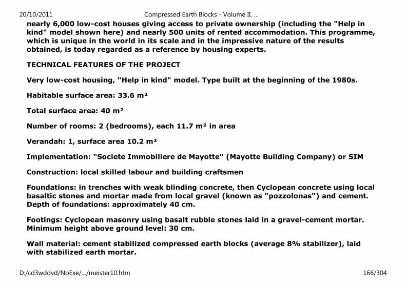
nearly 6,000 low-cost houses giving access to private ownership (including the "Help in
kind" model shown here) and nearly 500 units of rented accommodation. This programme,
which is unique in the world in its scale and in the impressive nature of the results
obtained, is today regarded as a reference by housing experts.
TECHNICAL FEATURES OF THE PROJECT
Very low-cost housing, "Help in kind" model. Type built at the beginning of the 1980s.
Habitable surface area: 33.6 m²
Total surface area: 40 m²
Number of rooms: 2 (bedrooms), each 11.7 m² in area
Verandah: 1, surface area 10.2 m²
Implementation: "Societe Immobiliere de Mayotte" (Mayotte Building Company) or SIM
Construction: local skilled labour and building craftsmen
Foundations: in trenches with weak blinding concrete, then Cyclopean concrete using local
basaltic stones and mortar made from local gravel (known as "pozzolonas") and cement.
Depth of foundations: approximately 40 cm.
Footings: Cyclopean masonry using basalt rubble stones laid in a gravel-cement mortar.
Minimum height above ground level: 30 cm.
Wall material: cement stabilized compressed earth blocks (average 8% stabilizer), laid
with stabilized earth mortar.
20/10/2011 Compressed Earth Blocks - Volume II. …
D:/cd3wddvd/NoExe/…/meister10.htm 166/304
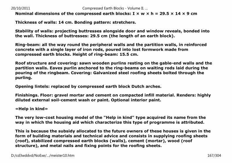
Nominal dimensions of the compressed earth blocks: I × w × h = 29.5 × 14 × 9 cm
Thickness of walls: 14 cm. Bonding pattern: stretchers.
Stability of walls: projecting buttresses alongside door and window reveals, bonded into
the wall. Thickness of buttresses: 29.5 cm (the length of an earth block).
Ring-beam: all the way round the peripheral walls and the partition walls, in reinforced
concrete with a single layer of iron rods, poured into lost formwork made from
compressed earth blocks. Height of ring-beam: 15.5 cm.
Roof structure and covering: sawn wooden purlins resting on the gable-end walls and the
partition walls. Eaves purlin anchored to the ring-beams on waiting rods laid during the
pouring of the ringbeam. Covering: Galvanized steel roofing sheets bolted through the
purling.
Opening lintels: replaced by compressed earth block Dutch arches.
Finishings. Floor: gravel mortar and cement on compacted infill material. Renders: highly
diluted external soil-cement wash or paint. Optional interior paint.
«Help in kind»
The very low-cost housing model of the "Help in kind" type acquired its name from the
way in which the housing aid which characterize this type of programme is attributed.
This is because the subsidy allocated to the future owners of these houses is given in the
form of building materials and technical advice and consists in supplying roofing sheets
(roof), stabilized compressed earth blocks (walls), cement (mortar), wood (roof
structure), and metal nails and fixing points for the roofing sheets.
20/10/2011 Compressed Earth Blocks - Volume II. …
D:/cd3wddvd/NoExe/…/meister10.htm 167/304
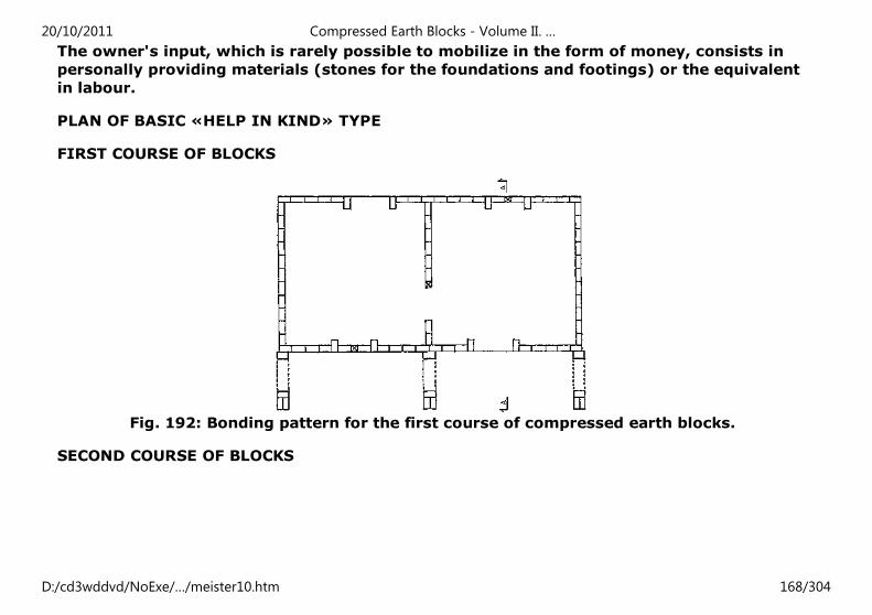
The owner's input, which is rarely possible to mobilize in the form of money, consists in
personally providing materials (stones for the foundations and footings) or the equivalent
in labour.
PLAN OF BASIC «HELP IN KIND» TYPE
FIRST COURSE OF BLOCKS
Fig. 192: Bonding pattern for the first course of compressed earth blocks.
SECOND COURSE OF BLOCKS
20/10/2011 Compressed Earth Blocks - Volume II. …
D:/cd3wddvd/NoExe/…/meister10.htm 168/304
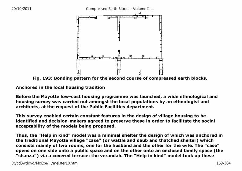
Fig. 193: Bonding pattern for the second course of compressed earth blocks.
Anchored in the local housing tradition
Before the Mayotte low-cost housing programme was launched, a wide ethnological and
housing survey was carried out amongst the local populations by an ethnologist and
architects, at the request of the Public Facilities department.
This survey enabled certain constant features in the design of village housing to be
identified and decision-makers agreed to preserve these in order to facilitate the social
acceptability of the models being proposed.
Thus, the "Help in kind" model was a minimal shelter the design of which was anchored in
the traditional Mayotte village "case" (or wattle and daub and thatched shelter) which
consists mainly of two rooms, one for the husband and the other for the wife. The "case"
opens on one side onto a public space and on the other onto an enclosed family space (the
"shanza") via a covered terrace: the verandah. The "Help in kind" model took up these
20/10/2011 Compressed Earth Blocks - Volume II. …
D:/cd3wddvd/NoExe/…/meister10.htm 169/304
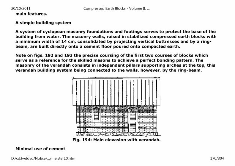
main features.
A simple building system
A system of cyclopean masonry foundations and footings serves to protect the base of the
building from water. The masonry walls, raised in stabilized compressed earth blocks with
a minimum width of 14 cm, consolidated by projecting vertical buttresses and by a ring-
beam, are built directly onto a cement floor poured onto compacted earth.
Note on figs. 192 and 193 the precise coursing of the first two courses of blocks which
serve as a reference for the skilled masons to achieve a perfect bonding pattern. The
masonry of the verandah consists in independent pillars supporting arches at the top, this
verandah building system being connected to the walls, however, by the ring-beam.
Fig. 194: Main elevasion with verandah.
Minimal use of cement
20/10/2011 Compressed Earth Blocks - Volume II. …
D:/cd3wddvd/NoExe/…/meister10.htm 170/304
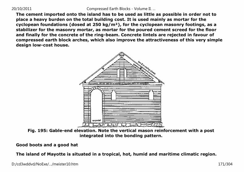
The cement imported onto the island has to be used as little as possible in order not to
place a heavy burden on the total building cost. It is used mainly as mortar for the
cyclopean foundations (dosed at 250 kg/m²), for the cyclopean masonry footings, as a
stabilizer for the masonry mortar, as mortar for the poured cement screed for the floor
and finally for the concrete of the ring-beam. Concrete lintels are rejected in favour of
compressed earth block arches, which also improve the attractiveness of this very simple
design low-cost house.
Fig. 195: Gable-end elevation. Note the vertical mason reinforcement with a post
integrated into the bonding pattern.
Good boots and a good hat
The island of Mayotte is situated in a tropical, hot, humid and maritime climatic region.
20/10/2011 Compressed Earth Blocks - Volume II. …
D:/cd3wddvd/NoExe/…/meister10.htm 171/304
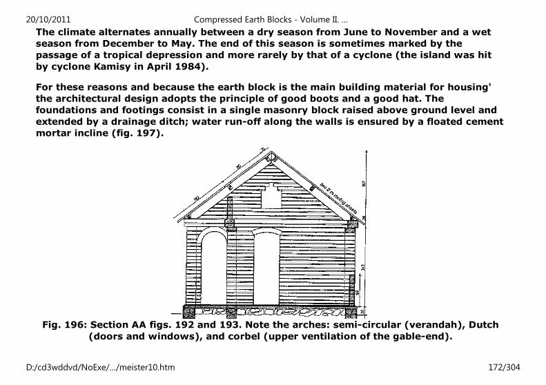
The climate alternates annually between a dry season from June to November and a wet
season from December to May. The end of this season is sometimes marked by the
passage of a tropical depression and more rarely by that of a cyclone (the island was hit
by cyclone Kamisy in April 1984).
For these reasons and because the earth block is the main building material for housing'
the architectural design adopts the principle of good boots and a good hat. The
foundations and footings consist in a single masonry block raised above ground level and
extended by a drainage ditch; water run-off along the walls is ensured by a floated cement
mortar incline (fig. 197).
Fig. 196: Section AA figs. 192 and 193. Note the arches: semi-circular (verandah), Dutch
(doors and windows), and corbel (upper ventilation of the gable-end).
20/10/2011 Compressed Earth Blocks - Volume II. …
D:/cd3wddvd/NoExe/…/meister10.htm 172/304
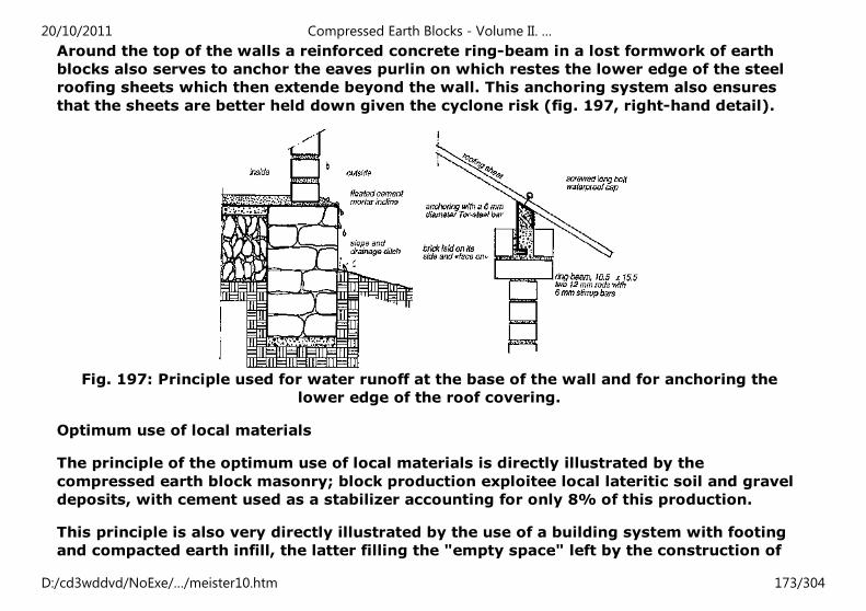
Around the top of the walls a reinforced concrete ring-beam in a lost formwork of earth
blocks also serves to anchor the eaves purlin on which restes the lower edge of the steel
roofing sheets which then extende beyond the wall. This anchoring system also ensures
that the sheets are better held down given the cyclone risk (fig. 197, right-hand detail).
Fig. 197: Principle used for water runoff at the base of the wall and for anchoring the
lower edge of the roof covering.
Optimum use of local materials
The principle of the optimum use of local materials is directly illustrated by the
compressed earth block masonry; block production exploitee local lateritic soil and gravel
deposits, with cement used as a stabilizer accounting for only 8% of this production.
This principle is also very directly illustrated by the use of a building system with footing
and compacted earth infill, the latter filling the "empty space" left by the construction of
20/10/2011 Compressed Earth Blocks - Volume II. …
D:/cd3wddvd/NoExe/…/meister10.htm 173/304
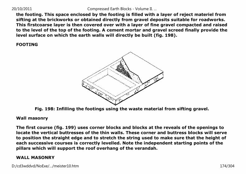
the footing. This space enclosed by the footing is filled with a layer of reject materiel from
sifting at the brickworks or obtained directly from gravel deposits suitable for roadworks.
This firstcoarse layer is then covered over with a layer of fine gravel compacted and raised
to the level of the top of the footing. A cement mortar and gravel screed finally provide the
level surface on which the earth walls will directly be built (fig. 198).
FOOTING
Fig. 198: Infilling the footings using the waste material from sifting gravel.
Wall masonry
The first course (fig. 199) uses corner blocks and blocks at the reveals of the openings to
locate the vertical buttresses of the thin walls. These corner and buttress blocks will serve
to position the straight edge and to stretch the string used to make sure that the height of
each successive courses is correctly levelled. Note the independent starting points of the
pillars which will support the roof overhang of the verandah.
WALL MASONRY
20/10/2011 Compressed Earth Blocks - Volume II. …
D:/cd3wddvd/NoExe/…/meister10.htm 174/304
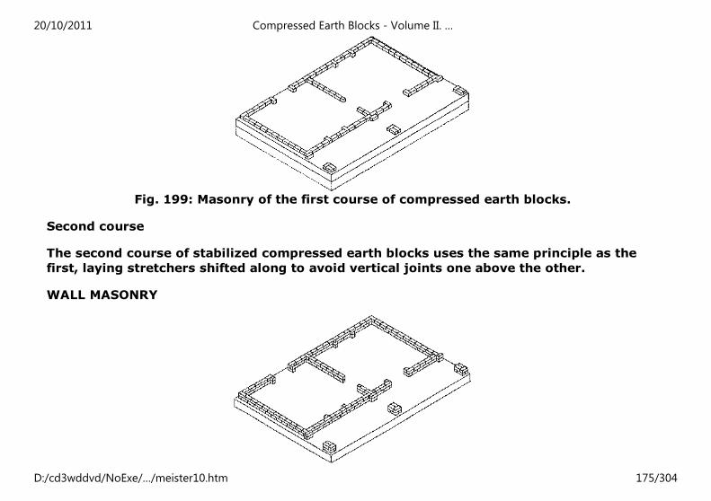
Fig. 199: Masonry of the first course of compressed earth blocks.
Second course
The second course of stabilized compressed earth blocks uses the same principle as the
first, laying stretchers shifted along to avoid vertical joints one above the other.
WALL MASONRY
20/10/2011 Compressed Earth Blocks - Volume II. …
D:/cd3wddvd/NoExe/…/meister10.htm 175/304
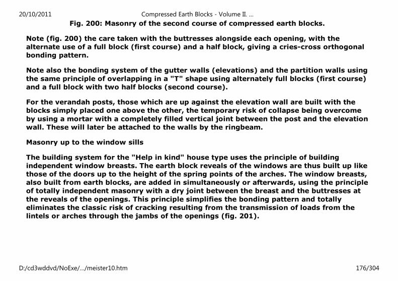
Fig. 200: Masonry of the second course of compressed earth blocks.
Note (fig. 200) the care taken with the buttresses alongside each opening, with the
alternate use of a full block (first course) and a half block, giving a cries-cross orthogonal
bonding pattern.
Note also the bonding system of the gutter walls (elevations) and the partition walls using
the same principle of overlapping in a "T" shape using alternately full blocks (first course)
and a full block with two half blocks (second course).
For the verandah posts, those which are up against the elevation wall are built with the
blocks simply placed one above the other, the temporary risk of collapse being overcome
by using a mortar with a completely filled vertical joint between the post and the elevation
wall. These will later be attached to the walls by the ringbeam.
Masonry up to the window sills
The building system for the "Help in kind" house type uses the principle of building
independent window breasts. The earth block reveals of the windows are thus built up like
those of the doors up to the height of the spring points of the arches. The window breasts,
also built from earth blocks, are added in simultaneously or afterwards, using the principle
of totally independent masonry with a dry joint between the breast and the buttresses at
the reveals of the openings. This principle simplifies the bonding pattern and totally
eliminates the classic risk of cracking resulting from the transmission of loads from the
lintels or arches through the jambs of the openings (fig. 201).
20/10/2011 Compressed Earth Blocks - Volume II. …
D:/cd3wddvd/NoExe/…/meister10.htm 176/304
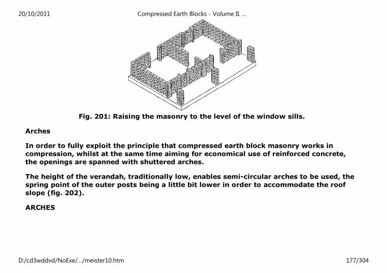
Fig. 201: Raising the masonry to the level of the window sills.
Arches
In order to fully exploit the principle that compressed earth block masonry works in
compression, whilst at the same time aiming for economical use of reinforced concrete,
the openings are spanned with shuttered arches.
The height of the verandah, traditionally low, enables semi-circular arches to be used, the
spring point of the outer posts being a little bit lower in order to accommodate the roof
slope (fig. 202).
ARCHES
20/10/2011 Compressed Earth Blocks - Volume II. …
D:/cd3wddvd/NoExe/…/meister10.htm 177/304
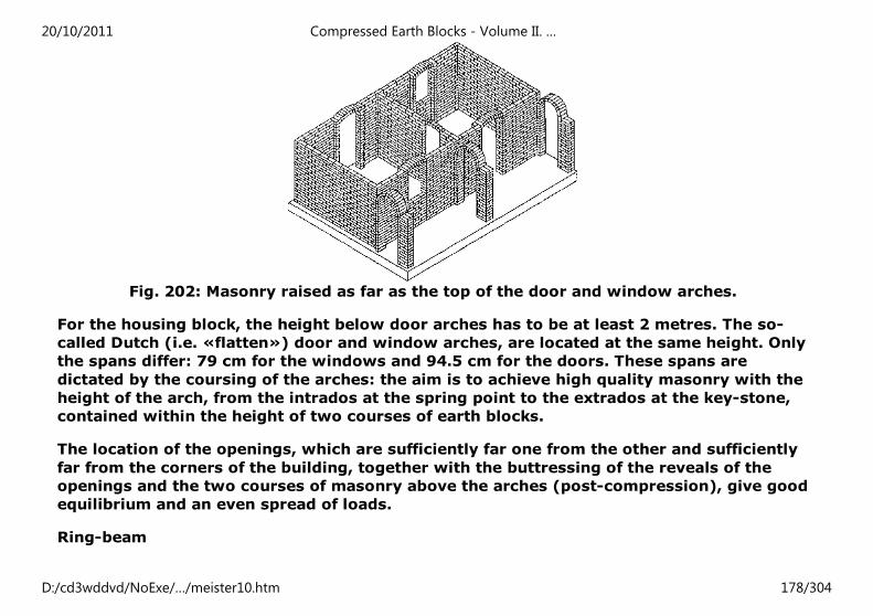
Fig. 202: Masonry raised as far as the top of the door and window arches.
For the housing block, the height below door arches has to be at least 2 metres. The so-
called Dutch (i.e. «flatten») door and window arches, are located at the same height. Only
the spans differ: 79 cm for the windows and 94.5 cm for the doors. These spans are
dictated by the coursing of the arches: the aim is to achieve high quality masonry with the
height of the arch, from the intrados at the spring point to the extrados at the key-stone,
contained within the height of two courses of earth blocks.
The location of the openings, which are sufficiently far one from the other and sufficiently
far from the corners of the building, together with the buttressing of the reveals of the
openings and the two courses of masonry above the arches (post-compression), give good
equilibrium and an even spread of loads.
Ring-beam
20/10/2011 Compressed Earth Blocks - Volume II. …
D:/cd3wddvd/NoExe/…/meister10.htm 178/304
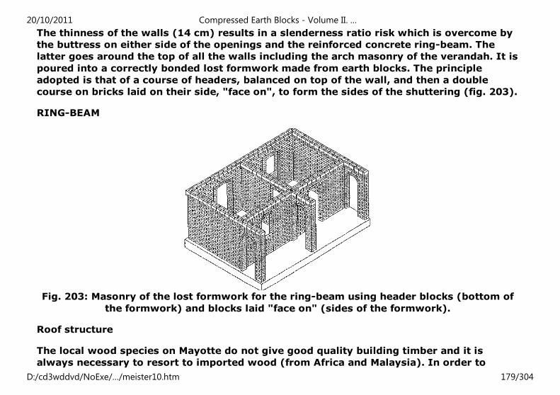
The thinness of the walls (14 cm) results in a slenderness ratio risk which is overcome by
the buttress on either side of the openings and the reinforced concrete ring-beam. The
latter goes around the top of all the walls including the arch masonry of the verandah. It is
poured into a correctly bonded lost formwork made from earth blocks. The principle
adopted is that of a course of headers, balanced on top of the wall, and then a double
course on bricks laid on their side, "face on", to form the sides of the shuttering (fig. 203).
RING-BEAM
Fig. 203: Masonry of the lost formwork for the ring-beam using header blocks (bottom of
the formwork) and blocks laid "face on" (sides of the formwork).
Roof structure
The local wood species on Mayotte do not give good quality building timber and it is
always necessary to resort to imported wood (from Africa and Malaysia). In order to
20/10/2011 Compressed Earth Blocks - Volume II. …
D:/cd3wddvd/NoExe/…/meister10.htm 179/304
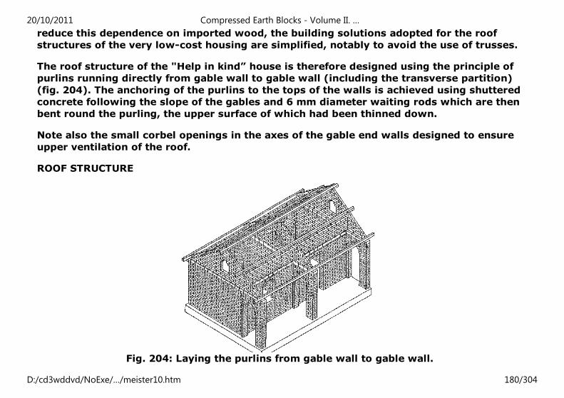
reduce this dependence on imported wood, the building solutions adopted for the roof
structures of the very low-cost housing are simplified, notably to avoid the use of trusses.
The roof structure of the "Help in kind” house is therefore designed using the principle of
purlins running directly from gable wall to gable wall (including the transverse partition)
(fig. 204). The anchoring of the purlins to the tops of the walls is achieved using shuttered
concrete following the slope of the gables and 6 mm diameter waiting rods which are then
bent round the purling, the upper surface of which had been thinned down.
Note also the small corbel openings in the axes of the gable end walls designed to ensure
upper ventilation of the roof.
ROOF STRUCTURE
Fig. 204: Laying the purlins from gable wall to gable wall.
20/10/2011 Compressed Earth Blocks - Volume II. …
D:/cd3wddvd/NoExe/…/meister10.htm 180/304
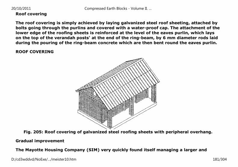
Roof covering
The roof covering is simply achieved by laying galvanized steel roof sheeting, attached by
bolts going through the purlins and covered with a water-proof cap. The attachment of the
lower edge of the roofing sheets is reinforced at the level of the eaves purlin, which lays
on the top of the verandah posts' at the end of the ring-beam, by 6 mm diameter rods laid
during the pouring of the ring-beam concrete which are then bent round the eaves purlin.
ROOF COVERING
Fig. 205: Roof covering of galvanized steel roofing sheets with peripheral overhang.
Gradual improvement
The Mayotte Housing Company (SIM) very quickly found itself managing a larger and
20/10/2011 Compressed Earth Blocks - Volume II. …
D:/cd3wddvd/NoExe/…/meister10.htm 181/304
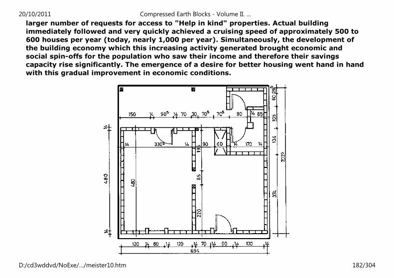
larger number of requests for access to "Help in kind" properties. Actual building
immediately followed and very quickly achieved a cruising speed of approximately 500 to
600 houses per year (today, nearly 1,000 per year). Simultaneously, the development of
the building economy which this increasing activity generated brought economic and
social spin-offs for the population who saw their income and therefore their savings
capacity rise significantly. The emergence of a desire for better housing went hand in hand
with this gradual improvement in economic conditions.
20/10/2011 Compressed Earth Blocks - Volume II. …
D:/cd3wddvd/NoExe/…/meister10.htm 182/304
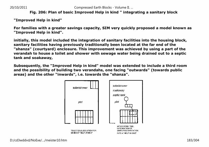
Fig. 206: Plan of basic Improved Help in kind " integrating a sanitary block
"Improved Help in kind"
For families with a greater savings capacity, SIM very quickly proposed a model known as
"Improved Help in kind".
initially, this model included the integration of sanitary facilities into the housing block,
sanitary facilities having previously traditionally been located at the far end of the
"shanza" (courtyard) enclosure. This improvement was achieved by using a part of the
verandah to house a toilet and shower with sewage water being drained out to a septic
tank and soakaway,
Subsequently, the "Improved Help in kind" model was extended to include a third room
and the possibility of building two verandahs, one facing "outwards" (towards public
areas) and the other "inwards", i.e. towards the "shanza".
20/10/2011 Compressed Earth Blocks - Volume II. …
D:/cd3wddvd/NoExe/…/meister10.htm 183/304
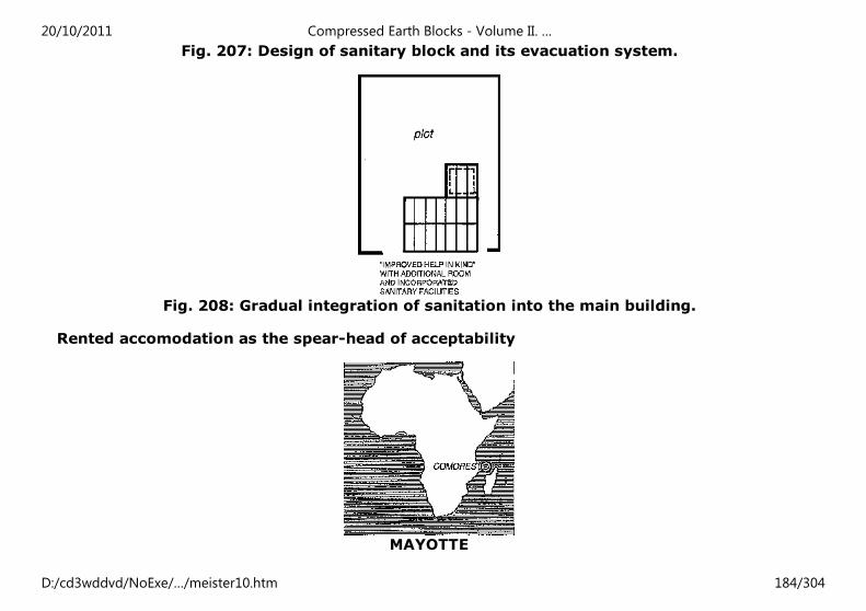
Fig. 207: Design of sanitary block and its evacuation system.
Fig. 208: Gradual integration of sanitation into the main building.
Rented accomodation as the spear-head of acceptability
MAYOTTE
20/10/2011 Compressed Earth Blocks - Volume II. …
D:/cd3wddvd/NoExe/…/meister10.htm 184/304
When the compressed earth block industry was set up on the island of Mayotte in 1981
and 1982, although its development was being encouraged by the political will of local
decision-makers and elected representatives, it was nevertheless not guaranteed. An
important stumbling-block had to be overcome: that of acceptability. At first, the
population of the island saw in the compressed earth block only a perpetuation of its own
tradition of building with earth. This perception did not correspond to the idea people had
of their own aspirations to modern housing, represented by the use of sand-cement blocks
and corrugated iron. And yet it was vital to use compressed earth blocks, for economic
reasons as much as for reasons of ecological balance, the island lacking its own sand. The
technical quality of the material and the quality of its architectural use had therefore to be
demonstrated in order to overcome this stumbling-block. The idea that the earth block
was a "below standard" material, reserved only for the very poor, had to be eliminated.
The approach thought up and immediately put into effect was to build rented
accommodation destined for expatriate civil servants using this material. The Passamainti
operation, undertaken in 1982, launched this and enabled the vital process of the earth
block being assimilated into building materials "en dur" (modern) to take place.
RENTED ACCOMMODATION ON MAYOTTE
This project was launched in the context of a mission for building pilot housing which was
implemented by CRATerre and the School of Architecture of Grenoble on behalf of the
Mayotte Housing Company (SIM). The project, which included starting up of a pilot
brickworks, was designed and implemented with the help of students from the school of
architecture, and mobilized local skilled labour from among the islanders. The design of
the eight houses included in the programme reflected the principle of echoing the layout of
traditional housing (small, long houses and enclosed private courtyards known as
"shanzas") and enabled building solutions to be developed (14 cm buttressed walls, earth
block lost formwork ring-beam, anchoring of the roof structure using a system of wooden
brackets, protective renders) which laid the foundations of techniques and an architectural
20/10/2011 Compressed Earth Blocks - Volume II. …
D:/cd3wddvd/NoExe/…/meister10.htm 185/304
and building vocabulary which was later to be used in subsequent generations of housing
projects. A "language" which was very rapidly assimilated and also very rapidly overtaken
by the blossoming of a genuine body of knowledge developed by architects settled on
Mayotte and by the island's building craftsmen.
TECHNICAL FEATURES OF THE PROJECT
Rented accomodation built in 1982.
Habitable surface area: from 2 to 4 main rooms, i.e. from 48 to 74 m².
Number of rooms:
- T2, 48 m²: two rooms, one kitchen with storeroom, one shower-W.C. L-shaped verandah
extension: 55 m².
- T3, 62 m²: three rooms, one kitchen with storeroom, one shower-W.C. L-shaped
verandah extension: 65 m².
- T4, 74 m²: four rooms, one kitchen with storeroom, one shower-W.C. U-shaped verandah
extension: 70 m².
- Enlarged T3 and enlarged T4: basically identical to T3 and T4, but with outside "paillote"
(thatched shelter) type living-room extension.
Owner: "Societe Immobiliere de Mayotte" (Mayotte Building Company) or SIM
Design: CRATerre - School of Architecture of Grenoble Construction: Chazuli and Alifina
contractors, Mayotte.
Foundations: in trenches with weak blinding concrete, then Cyclopean concrete made
20/10/2011 Compressed Earth Blocks - Volume II. …
D:/cd3wddvd/NoExe/…/meister10.htm 186/304
using local basaltic stones and mortar made from local gravel (known as "pozzolonas")
and cement. Depth of foundations: approximately 40 cm.
Footings: Cyclopean masonry using basalt rubble stones laid in a gravel-cement mortar.
Minimum height: 30 cm.
Wall material: cement stabilized compressed earth blocks (average 8% stabilizer), laid
with stabilized earth mortar.
Nominal dimension: I × w × h = 29.5 × 14 × 9 cm. Thickness of walls: 14 cm. Bonding
pattern: stretchers.
Stability of walls: projecting buttresses alongside door and window reveals, bonded into
the wall. Thickness of buttress: 29.5 cm.
Ring-beam: all the way round the peripheral walls and the partition walls, in reinforced
concrete with a single layer of iron rods, poured into lost formwork made from stabilized
compressed earth blocks. Height of ring-beam: 15.5 cm.
Roof structure and covering: sawn wooden purlins running from the gable-end walls to
the partition walls. Eaves purlins anchored to the ring-beams on waiting rods laid during
the pouring of the ring-beam. Covering: galvanized steel roofing sheets bolted through the
purling.
Opening lintels: replaced by compressed earth block Dutch arches.
Finishings. Floor: gravel mortar and cement on compacted infill material. Renders: highly
diluted external soil-cement wash or paint. Optional interior paint.
Architectural design of the housing
20/10/2011 Compressed Earth Blocks - Volume II. …
D:/cd3wddvd/NoExe/…/meister10.htm 187/304
The eight houses built at Passamainti showed the possibilities of progressive extensions
starting from a simple basic “Help in kind” type house which corresponded to the island's
very low-cost housing. The first improvement consisted in adding a kitchen-sanitary block
located at right angles to the main housing block and looking out over the interior private
courtyard. This addition continued to keep the toilet as far as possible away from the
living area and thus, whilst making a significant improvement, also satisfied the island
habit of always banishing this area to the far end of the “shanza”. The second stage of
change added a third room to the house, by extending on from the other two towards the
“outside”. This T3 type already prefigured what was later to become the “Improved Help
in Kind”, offered to the islanders who had more savings. The following stages consisted in
gradually enclosing the central open area, i.e. transforming then L-shaped layout of the T2
and T3 into the U-shaped layout of the enlarged T3 and T4. The most particular
characteristic of these houses, which had to meet the basic comfort requirements of a
French expatriate community, consisted in the way in which the verandahs were used as
genuine covered terraces, both spacious and serving as dining areas and living-rooms.
«SHANZA» ENCLOSURE
T3 HOUSING TYPE
20/10/2011 Compressed Earth Blocks - Volume II. …
D:/cd3wddvd/NoExe/…/meister10.htm 188/304
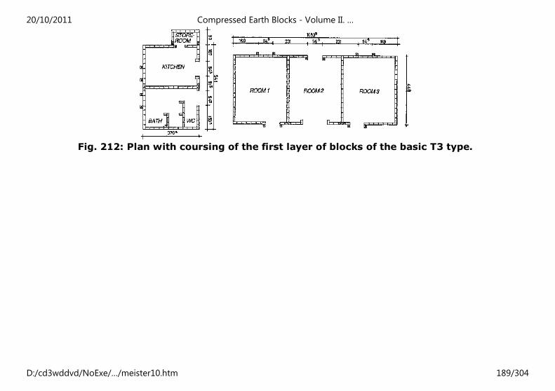
Fig. 212: Plan with coursing of the first layer of blocks of the basic T3 type.
20/10/2011 Compressed Earth Blocks - Volume II. …
D:/cd3wddvd/NoExe/…/meister10.htm 189/304
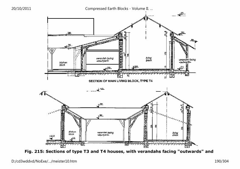
Fig. 215: Sections of type T3 and T4 houses, with verandahs facing "outwards" and
20/10/2011 Compressed Earth Blocks - Volume II. …
D:/cd3wddvd/NoExe/…/meister10.htm 190/304
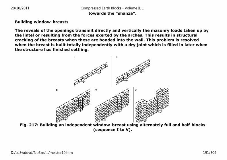
towards the "shanza".
Building window-breasts
The reveals of the openings transmit directly and vertically the masonry loads taken up by
the lintel or resulting from the forces exerted by the arches. This results in structural
cracking of the breasts when these are bonded into the wall. This problem is resolved
when the breast is built totally independently with a dry joint which is filled in later when
the structure has finished settling.
Fig. 217: Building an independent window-breast using alternately full and half-blocks
(sequence I to V).
20/10/2011 Compressed Earth Blocks - Volume II. …
D:/cd3wddvd/NoExe/…/meister10.htm 191/304
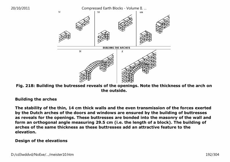
Fig. 218: Building the butressed reveals of the openings. Note the thickness of the arch on
the outside.
Building the arches
The stability of the thin, 14 cm thick walls and the even transmission of the forces exerted
by the Dutch arches of the doors and windows are ensured by the building of buttresses
as reveals for the openings. These buttresses are bonded into the masonry of the wall and
form an orthogonal angle measuring 29.5 cm (i.e. the length of a block). The building of
arches of the same thickness as these buttresses add an attractive feature to the
elevation.
Design of the elevations
20/10/2011 Compressed Earth Blocks - Volume II. …
D:/cd3wddvd/NoExe/…/meister10.htm 192/304
The elevations of the eight Passamainti houses use a very simple design. The aesthetic
effect is achieved solely by the positioning of the openings, which are disposed
symmetrically on either side of the central door on the "outward" side, and on either side
of the main door on the "shanza" side. (The central door on the "outward" side could
eventually become a window by infilling a window breast). To this symmetrical layout, is
added the projecting effect of the buttresses on either side of the window reveals. The
harmony of the large earth block exposed wall is expressed through the regular courses of
blocks and the horizontality of the strip of ring-beam which also projects at the top of the
elevations.
20/10/2011 Compressed Earth Blocks - Volume II. …
D:/cd3wddvd/NoExe/…/meister10.htm 193/304
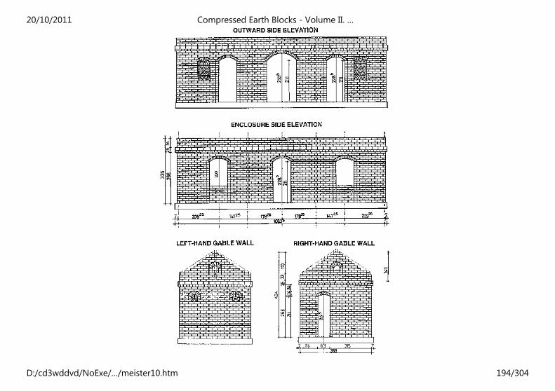
20/10/2011 Compressed Earth Blocks - Volume II. …
D:/cd3wddvd/NoExe/…/meister10.htm 194/304
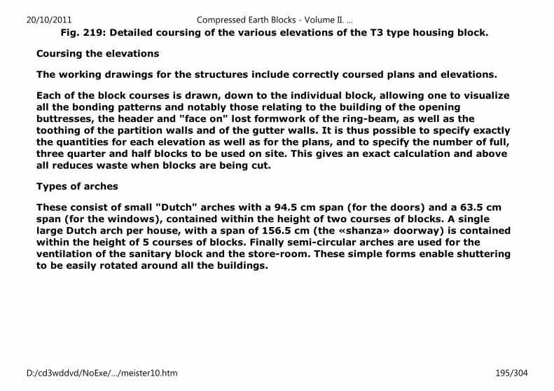
Fig. 219: Detailed coursing of the various elevations of the T3 type housing block.
Coursing the elevations
The working drawings for the structures include correctly coursed plans and elevations.
Each of the block courses is drawn, down to the individual block, allowing one to visualize
all the bonding patterns and notably those relating to the building of the opening
buttresses, the header and "face on" lost formwork of the ring-beam, as well as the
toothing of the partition walls and of the gutter walls. It is thus possible to specify exactly
the quantities for each elevation as well as for the plans, and to specify the number of full,
three quarter and half blocks to be used on site. This gives an exact calculation and above
all reduces waste when blocks are being cut.
Types of arches
These consist of small "Dutch" arches with a 94.5 cm span (for the doors) and a 63.5 cm
span (for the windows), contained within the height of two courses of blocks. A single
large Dutch arch per house, with a span of 156.5 cm (the «shanza» doorway) is contained
within the height of 5 courses of blocks. Finally semi-circular arches are used for the
ventilation of the sanitary block and the store-room. These simple forms enable shuttering
to be easily rotated around all the buildings.
20/10/2011 Compressed Earth Blocks - Volume II. …
D:/cd3wddvd/NoExe/…/meister10.htm 195/304
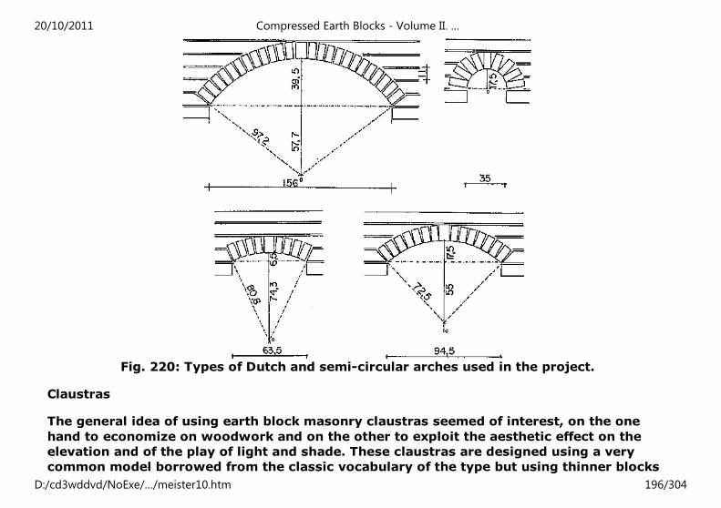
Fig. 220: Types of Dutch and semi-circular arches used in the project.
Claustras
The general idea of using earth block masonry claustras seemed of interest, on the one
hand to economize on woodwork and on the other to exploit the aesthetic effect on the
elevation and of the play of light and shade. These claustras are designed using a very
common model borrowed from the classic vocabulary of the type but using thinner blocks
20/10/2011 Compressed Earth Blocks - Volume II. …
D:/cd3wddvd/NoExe/…/meister10.htm 196/304
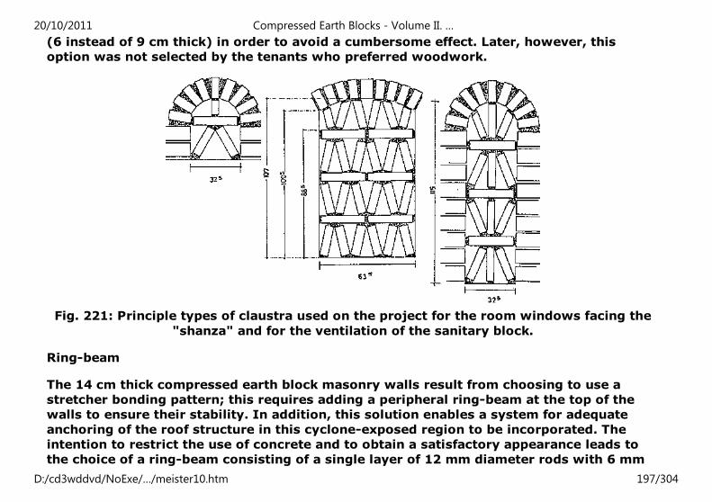
(6 instead of 9 cm thick) in order to avoid a cumbersome effect. Later, however, this
option was not selected by the tenants who preferred woodwork.
Fig. 221: Principle types of claustra used on the project for the room windows facing the
"shanza" and for the ventilation of the sanitary block.
Ring-beam
The 14 cm thick compressed earth block masonry walls result from choosing to use a
stretcher bonding pattern; this requires adding a peripheral ring-beam at the top of the
walls to ensure their stability. In addition, this solution enables a system for adequate
anchoring of the roof structure in this cyclone-exposed region to be incorporated. The
intention to restrict the use of concrete and to obtain a satisfactory appearance leads to
the choice of a ring-beam consisting of a single layer of 12 mm diameter rods with 6 mm
20/10/2011 Compressed Earth Blocks - Volume II. …
D:/cd3wddvd/NoExe/…/meister10.htm 197/304
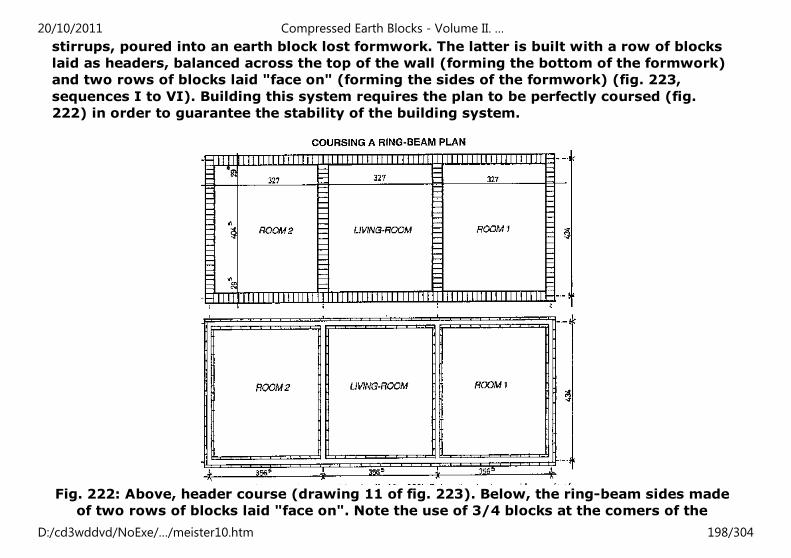
stirrups, poured into an earth block lost formwork. The latter is built with a row of blocks
laid as headers, balanced across the top of the wall (forming the bottom of the formwork)
and two rows of blocks laid "face on" (forming the sides of the formwork) (fig. 223,
sequences I to VI). Building this system requires the plan to be perfectly coursed (fig.
222) in order to guarantee the stability of the building system.
Fig. 222: Above, header course (drawing 11 of fig. 223). Below, the ring-beam sides made
of two rows of blocks laid "face on". Note the use of 3/4 blocks at the comers of the
20/10/2011 Compressed Earth Blocks - Volume II. …
D:/cd3wddvd/NoExe/…/meister10.htm 198/304
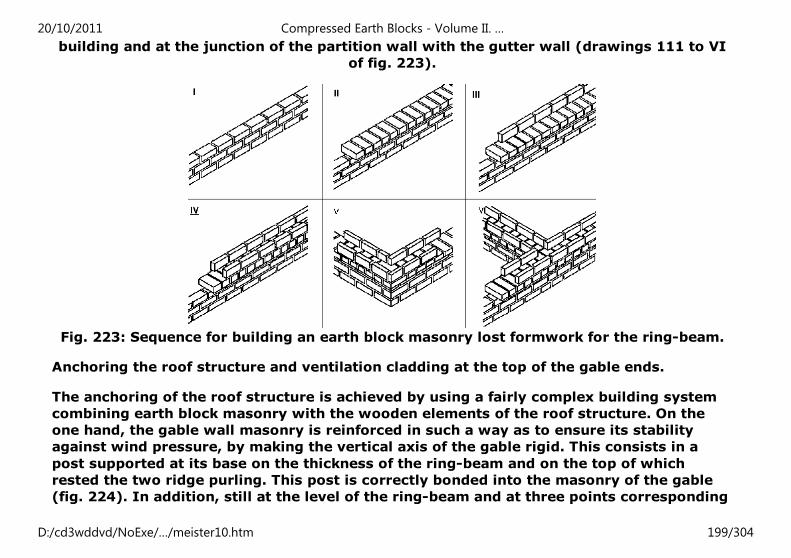
building and at the junction of the partition wall with the gutter wall (drawings 111 to VI
of fig. 223).
Fig. 223: Sequence for building an earth block masonry lost formwork for the ring-beam.
Anchoring the roof structure and ventilation cladding at the top of the gable ends.
The anchoring of the roof structure is achieved by using a fairly complex building system
combining earth block masonry with the wooden elements of the roof structure. On the
one hand, the gable wall masonry is reinforced in such a way as to ensure its stability
against wind pressure, by making the vertical axis of the gable rigid. This consists in a
post supported at its base on the thickness of the ring-beam and on the top of which
rested the two ridge purling. This post is correctly bonded into the masonry of the gable
(fig. 224). In addition, still at the level of the ring-beam and at three points corresponding
20/10/2011 Compressed Earth Blocks - Volume II. …
D:/cd3wddvd/NoExe/…/meister10.htm 199/304
to the vertical of the two intermediate purlins and of the two ridge purling, wooden
brackets piercing the gable wall on either side hold the purlins in place with screwed
braces (figs. 224 and 225). Firm anchoring is also ensured at the level of the eaves purlins
by attaching them to the ring-beam using 6 mm diameter rods previously put into place
during pouring and then bent back over the purlin, the upper part of which had been pared
down. This system for anchoring the roof structure into the gable walls and the gutter
walls (lower edge) proved very efficient when put to the test by the passage of cyclone
"Kamisy" in April 1984. Finally, a system of cladding using overlapping wooden planks on
a triangular structure attached to the anchoring braces provides ventilation at the top of
the gable.
20/10/2011 Compressed Earth Blocks - Volume II. …
D:/cd3wddvd/NoExe/…/meister10.htm 200/304
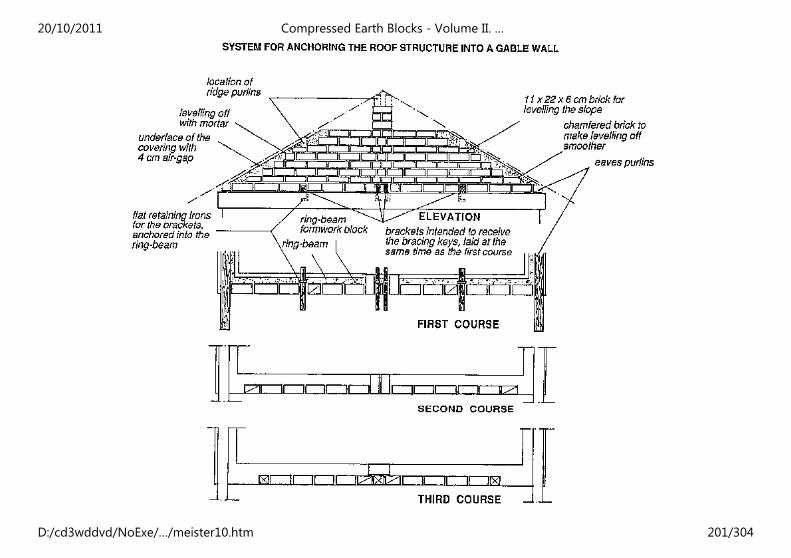
20/10/2011 Compressed Earth Blocks - Volume II. …
D:/cd3wddvd/NoExe/…/meister10.htm 201/304
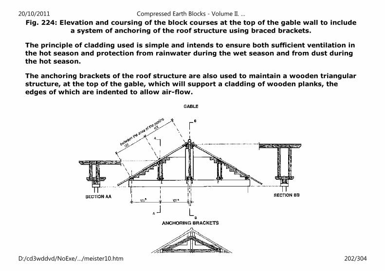
Fig. 224: Elevation and coursing of the block courses at the top of the gable wall to include
a system of anchoring of the roof structure using braced brackets.
The principle of cladding used is simple and intends to ensure both sufficient ventilation in
the hot season and protection from rainwater during the wet season and from dust during
the hot season.
The anchoring brackets of the roof structure are also used to maintain a wooden triangular
structure, at the top of the gable, which will support a cladding of wooden planks, the
edges of which are indented to allow air-flow.
20/10/2011 Compressed Earth Blocks - Volume II. …
D:/cd3wddvd/NoExe/…/meister10.htm 202/304
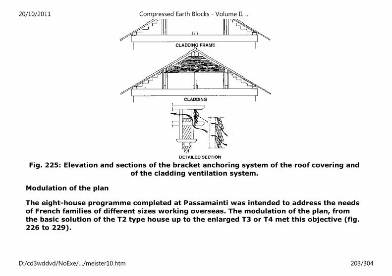
Fig. 225: Elevation and sections of the bracket anchoring system of the roof covering and
of the cladding ventilation system.
Modulation of the plan
The eight-house programme completed at Passamainti was intended to address the needs
of French families of different sizes working overseas. The modulation of the plan, from
the basic solution of the T2 type house up to the enlarged T3 or T4 met this objective (fig.
226 to 229).
20/10/2011 Compressed Earth Blocks - Volume II. …
D:/cd3wddvd/NoExe/…/meister10.htm 203/304
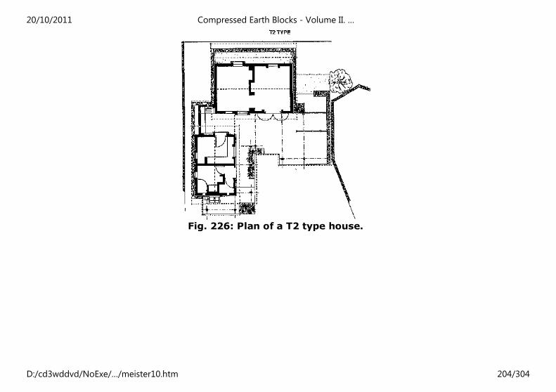
Fig. 226: Plan of a T2 type house.
20/10/2011 Compressed Earth Blocks - Volume II. …
D:/cd3wddvd/NoExe/…/meister10.htm 204/304
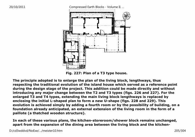
Fig. 227: Plan of a T3 type house.
The principle adopted is to enlarge the plan of the living block, lengthways, thus
respecting the traditional evolution of the island house which served as a reference point
during the design stage of the project. This addition could be made directly and without
introducing any major change between the T2 and T3 types (figs. 226 and 227). For the
enlarged T3 and T4 types, extending the main living block lengthways is replaced by
enclosing the initial L-shaped plan to form a new U-shape (figs. 228 and 229). This
evolution is achieved simply by adding a fourth room or by the possibility of building, on a
foundation already anticipated, an external extension of the living room in the form of a
paillote (a thatched wooden structure).
In each of these various plans, the kitchen-storeroom/shower block remains unchanged,
apart from the expansion of the dining area between the living block and the kitchen-
20/10/2011 Compressed Earth Blocks - Volume II. …
D:/cd3wddvd/NoExe/…/meister10.htm 205/304
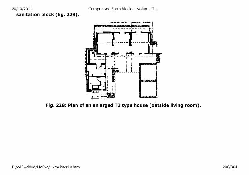
sanitation block (fig. 229).
Fig. 228: Plan of an enlarged T3 type house (outside living room).
20/10/2011 Compressed Earth Blocks - Volume II. …
D:/cd3wddvd/NoExe/…/meister10.htm 206/304
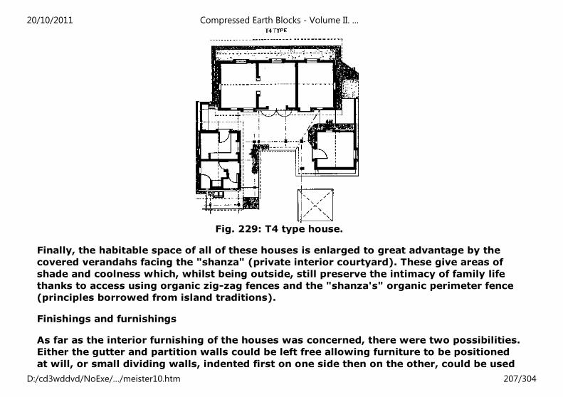
Fig. 229: T4 type house.
Finally, the habitable space of all of these houses is enlarged to great advantage by the
covered verandahs facing the "shanza" (private interior courtyard). These give areas of
shade and coolness which, whilst being outside, still preserve the intimacy of family life
thanks to access using organic zig-zag fences and the "shanza's" organic perimeter fence
(principles borrowed from island traditions).
Finishings and furnishings
As far as the interior furnishing of the houses was concerned, there were two possibilities.
Either the gutter and partition walls could be left free allowing furniture to be positioned
at will, or small dividing walls, indented first on one side then on the other, could be used
20/10/2011 Compressed Earth Blocks - Volume II. …
D:/cd3wddvd/NoExe/…/meister10.htm 207/304
to form cupboard alcoves. This second solution, which proves trickier to build, is however
much appreciated by the occupants. The interior floor does not receive any special
finishing treatment other than a floor paint on the cement mortar surface.
For doors and windows, single or doublepane woodwork are used; ventilation is achieved
by slatted shutters or doublesided frames (windows) with three positions for adjusting
the slope of the opening and thus modifying ventilation and lighting at will.
For the wall finishings, outside a highly-diluted soil-cement wash is used, and inside
either white-wash or paint.
As for outside fittings, attention should be drawn mainly to the use of organic panels of
"huanza" (woven coconut palm leaves) to build the access and to enclose the "shanza"
with zig-zag fences.
Impact of the operation
Being close to the village of Passamainti the implementation of this operation had an
immediate impact on the local population which was able to see for themselves the quality
of the material and of the execution of the work. In addition, the building solutions
adopted, which were innovatory, had important repercussions on the building methods
used subsequently on Mayotte. Finally, the site allowed the first island contractors to be
trained and since then these have worked regularly for SIM on social and rented housing
programmes.
From traditional to modern
20/10/2011 Compressed Earth Blocks - Volume II. …
D:/cd3wddvd/NoExe/…/meister10.htm 208/304
MOROCCO
Located in Morocco, a country with a rich tradition of earth building, the architectural
heritage of which is considered to be amongst the most stunning in the world, the housing
project implemented in Marrakesh - Hay al Massira paved the way for an updating of
Moroccan skills and knowledge in an urban context and threw a bridge between traditional
and modern. This building method is still well integrated into the rural economies of the
southern regions of the country, but for several decades had deserted the towns which
still, however, bore witness to both its utility and its excellence (the «medina» of
Marrakesh for example). Moroccan towns are experiencing significant growth and
contemporary building materials are often prohibitively expensive. It was in an attempt to
find other solutions that Moroccan institutions decided, during the 1980s, to relaunch the
use of earth in relation to housing in urban contexts.
FOUR HOUSES AT MARRAKESH HAY AL MASSIRA
Project context and objectives
Launched and implemented between 1983 and 1986-87, the Marrakesh - Hay al Massira
project for the construction of earth block housing arose in the context of a bilateral
20/10/2011 Compressed Earth Blocks - Volume II. …
D:/cd3wddvd/NoExe/…/meister10.htm 209/304
cooperation activity between France (the cooperation experimental research programme,
Rexcoop) and Morocco, on the initiative of an important governmental housing planner
and estate establishment from the southern region, Erac-Tensift, in Marrakesh. This
cooperation was founded notably on the basis of the French experimentation developed on
the «romaine de la Terre» (Earth Domain) project of Isle d'Abeau (near Lyon, France)
which inspired a similar approach amongst Moroccan land-use and construction decision-
makers.
The Marrakesh project envisaged the construction of 60 «intermediate», type housing
units in a semi-rural zone (the outskirts of Marrakesh) of high or medium quality image in
urban or pert-urban contexts. The project aimed to up-date Moroccan skills and
knowledge, hoped to help to overcome the barriers erected by builders and end-users,
aimed to integrate earth building into a legal, judicial and technical framework and a
genuine economic framework, and finally hoped to relaunch experimentation on the theme
of the use of local materials and innovatory building solutions.
TECHNICAL FEATURES OF THE PROJECT
Experimental phase of the project: 2 houses with a total surface area of 305 m².
- Project funding: CIH - Credit immobilier hotelier (Hotel building credit).
- Research, experimentation and technical assistance funding: FAC - Fonds d'aide et de
cooperation (Aid and cooperation fund), in the context of the French interministerial
programme, REXCOOP.
- Owner: The regional land-use and building establishment of the Tensift region
(Marrakesh), ERAC-Tensift and the Ministry of housing and land-use, Rabat, Morocco.
- Design: Abderrahmane Chorfi, Architect, Rabat, Morocco; with technical assistance from
20/10/2011 Compressed Earth Blocks - Volume II. …
D:/cd3wddvd/NoExe/…/meister10.htm 210/304
Jean-Vincent Berlottier, architect at Bourg-en-Bresse, France.
- Implementation: ERCT, Elie Mouyal, architect and contractor, Marrakesh, Morocco.
- Coordination of technical and architectural assistance and training: CRATerre, Grenoble.
- Technical assistance with building materials: Altech company, Embrun, and the School of
Architecture of St-Etienne, France.
- Assistance with follow-up of the operation: GAITERRE, Marrakesh, Morocco.
- Technical evaluation: DCTC, Rabat, LPEE, Casablanca and the regional delegation of
Marrakesh, BET Promoconsult, Casablanca, Morocco.
- Wall construction materials: stabilized compressed earth blocks (29.5 × 14 × 9 cm) and
vibration-compacted earth blocks (20 × 20 × 40 cm).
- Foundations: reinforced concrete (ground beams).
- Experimental building systems: earth block vaulting flooring supported by reinforced
concrete girders. Spanning of openings using reinforced concrete lintels (for 20 × 20 × 40
cm masonry blocks) and using earth block depressed arches (for 29.5 × 14 × 9 cm
masonry blocks).
- Updating of traditional technical solutions such as: interior plaster and «tadellakt»
(closed quick lime) renders, floors in polished granite or cement tiles. Terraced roofs
protected by a «dess» (earth and tamped lime mortar).
Architectural and building concept
The possible built surface area of the plots is 150 m², with potential for two storeys. The
20/10/2011 Compressed Earth Blocks - Volume II. …
D:/cd3wddvd/NoExe/…/meister10.htm 211/304
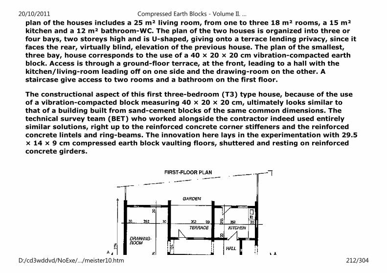
plan of the houses includes a 25 m² living room, from one to three 18 m² rooms, a 15 m²
kitchen and a 12 m² bathroom-WC. The plan of the two houses is organized into three or
four bays, two storeys high and is U-shaped, giving onto a terrace lending privacy, since it
faces the rear, virtually blind, elevation of the previous house. The plan of the smallest,
three bay, house corresponds to the use of a 40 × 20 × 20 cm vibration-compacted earth
block. Access is through a ground-floor terrace, at the front, leading to a hall with the
kitchen/living-room leading off on one side and the drawing-room on the other. A
staircase give access to two rooms and a bathroom on the first floor.
The constructional aspect of this first three-bedroom (T3) type house, because of the use
of a vibration-compacted block measuring 40 × 20 × 20 cm, ultimately looks similar to
that of a building built from sand-cement blocks of the same common dimensions. The
technical survey team (BET) who worked alongside the contractor indeed used entirely
similar solutions, right up to the reinforced concrete corner stiffeners and the reinforced
concrete lintels and ring-beams. The innovation here lays in the experimentation with 29.5
× 14 × 9 cm compressed earth block vaulting floors, shuttered and resting on reinforced
concrete girders.
20/10/2011 Compressed Earth Blocks - Volume II. …
D:/cd3wddvd/NoExe/…/meister10.htm 212/304
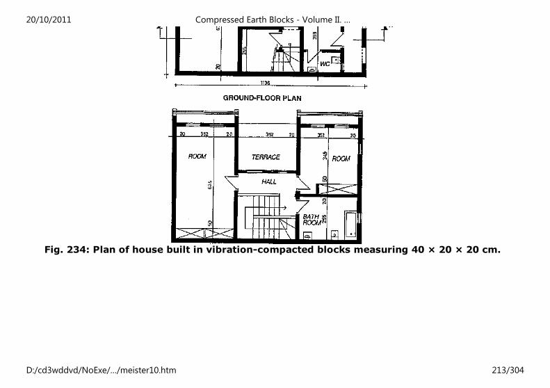
Fig. 234: Plan of house built in vibration-compacted blocks measuring 40 × 20 × 20 cm.
20/10/2011 Compressed Earth Blocks - Volume II. …
D:/cd3wddvd/NoExe/…/meister10.htm 213/304
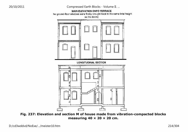
Fig. 237: Elevation and section M of house made from vibration-compacted blocks
measuring 40 × 20 × 20 cm.
20/10/2011 Compressed Earth Blocks - Volume II. …
D:/cd3wddvd/NoExe/…/meister10.htm 214/304
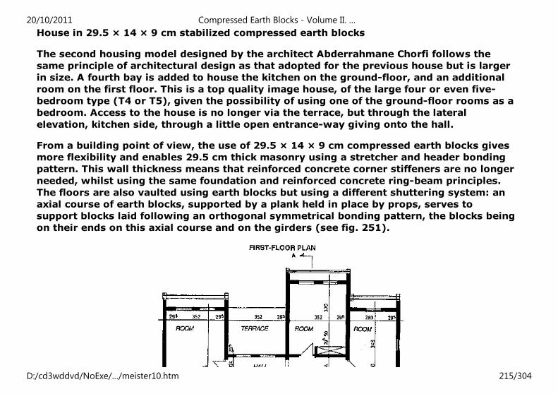
House in 29.5 × 14 × 9 cm stabilized compressed earth blocks
The second housing model designed by the architect Abderrahmane Chorfi follows the
same principle of architectural design as that adopted for the previous house but is larger
in size. A fourth bay is added to house the kitchen on the ground-floor, and an additional
room on the first floor. This is a top quality image house, of the large four or even five-
bedroom type (T4 or T5), given the possibility of using one of the ground-floor rooms as a
bedroom. Access to the house is no longer via the terrace, but through the lateral
elevation, kitchen side, through a little open entrance-way giving onto the hall.
From a building point of view, the use of 29.5 × 14 × 9 cm compressed earth blocks gives
more flexibility and enables 29.5 cm thick masonry using a stretcher and header bonding
pattern. This wall thickness means that reinforced concrete corner stiffeners are no longer
needed, whilst using the same foundation and reinforced concrete ring-beam principles.
The floors are also vaulted using earth blocks but using a different shuttering system: an
axial course of earth blocks, supported by a plank held in place by props, serves to
support blocks laid following an orthogonal symmetrical bonding pattern, the blocks being
on their ends on this axial course and on the girders (see fig. 251).
20/10/2011 Compressed Earth Blocks - Volume II. …
D:/cd3wddvd/NoExe/…/meister10.htm 215/304
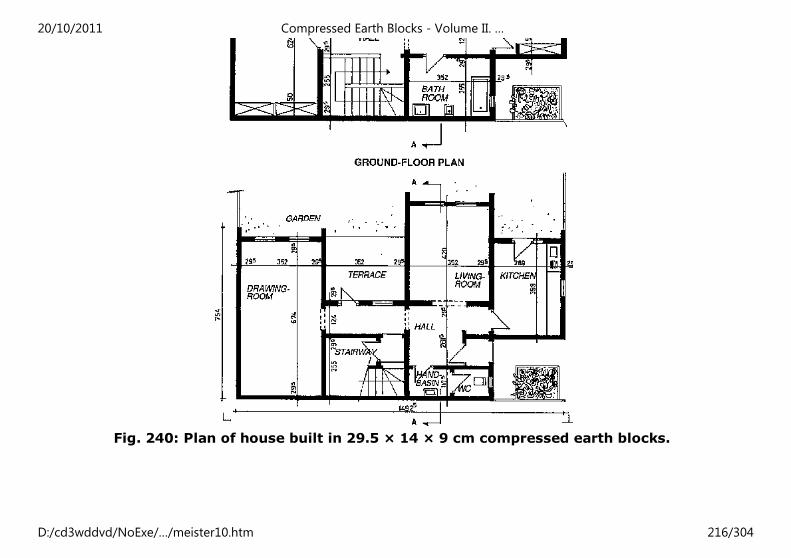
Fig. 240: Plan of house built in 29.5 × 14 × 9 cm compressed earth blocks.
20/10/2011 Compressed Earth Blocks - Volume II. …
D:/cd3wddvd/NoExe/…/meister10.htm 216/304
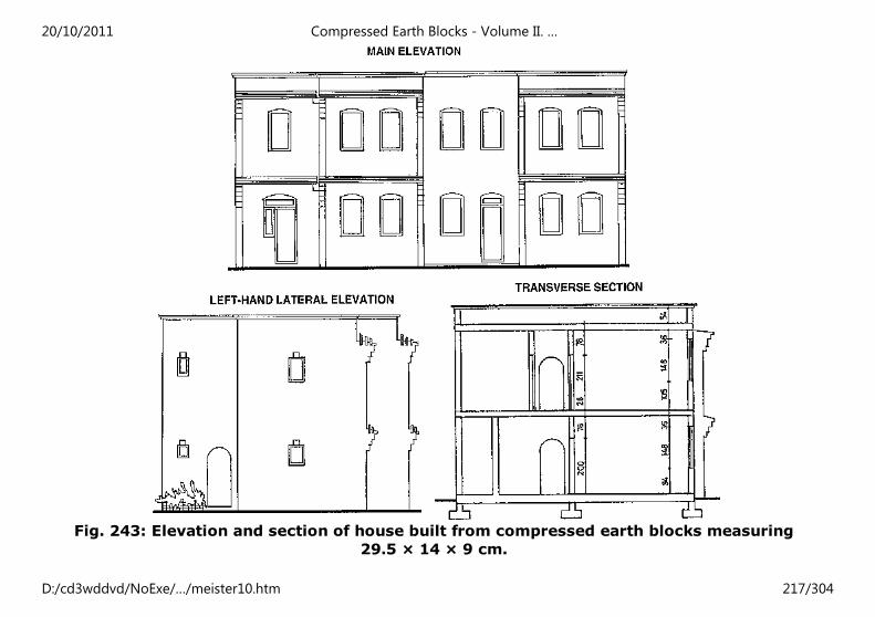
Fig. 243: Elevation and section of house built from compressed earth blocks measuring
29.5 × 14 × 9 cm.
20/10/2011 Compressed Earth Blocks - Volume II. …
D:/cd3wddvd/NoExe/…/meister10.htm 217/304
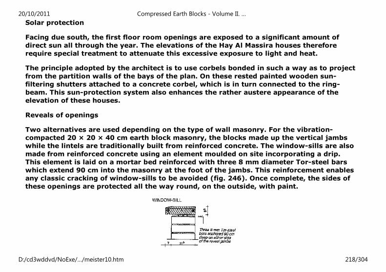
Solar protection
Facing due south, the first floor room openings are exposed to a significant amount of
direct sun all through the year. The elevations of the Hay Al Massira houses therefore
require special treatment to attenuate this excessive exposure to light and heat.
The principle adopted by the architect is to use corbels bonded in such a way as to project
from the partition walls of the bays of the plan. On these rested painted wooden sun-
filtering shutters attached to a concrete corbel, which is in turn connected to the ring-
beam. This sun-protection system also enhances the rather austere appearance of the
elevation of these houses.
Reveals of openings
Two alternatives are used depending on the type of wall masonry. For the vibration-
compacted 20 × 20 × 40 cm earth block masonry, the blocks made up the vertical jambs
while the lintels are traditionally built from reinforced concrete. The window-sills are also
made from reinforced concrete using an element moulded on site incorporating a drip.
This element is laid on a mortar bed reinforced with three 8 mm diameter Tor-steel bars
which extend 90 cm into the masonry at the foot of the jambs. This reinforcement enables
any classic cracking of window-sills to be avoided (fig. 246). Once complete, the sides of
these openings are protected all the way round, on the outside, with paint.
20/10/2011 Compressed Earth Blocks - Volume II. …
D:/cd3wddvd/NoExe/…/meister10.htm 218/304
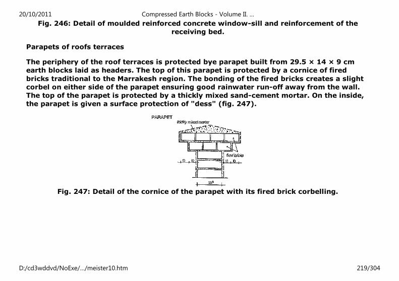
Fig. 246: Detail of moulded reinforced concrete window-sill and reinforcement of the
receiving bed.
Parapets of roofs terraces
The periphery of the roof terraces is protected bye parapet built from 29.5 × 14 × 9 cm
earth blocks laid as headers. The top of this parapet is protected by a cornice of fired
bricks traditional to the Marrakesh region. The bonding of the fired bricks creates a slight
corbel on either side of the parapet ensuring good rainwater run-off away from the wall.
The top of the parapet is protected by a thickly mixed sand-cement mortar. On the inside,
the parapet is given a surface protection of "dess" (fig. 247).
Fig. 247: Detail of the cornice of the parapet with its fired brick corbelling.
20/10/2011 Compressed Earth Blocks - Volume II. …
D:/cd3wddvd/NoExe/…/meister10.htm 219/304
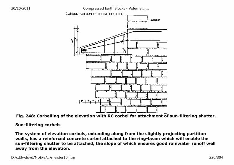
Fig. 248: Corbelling of the elevation with RC corbel for attachment of sun-filtering shutter.
Sun-filtering corbels
The system of elevation corbels, extending along from the slightly projecting partition
walls, has a reinforced concrete corbel attached to the ring-beam which will enable the
sun-filtering shutter to be attached, the slope of which ensures good rainwater runoff well
away from the elevation.
20/10/2011 Compressed Earth Blocks - Volume II. …
D:/cd3wddvd/NoExe/…/meister10.htm 220/304
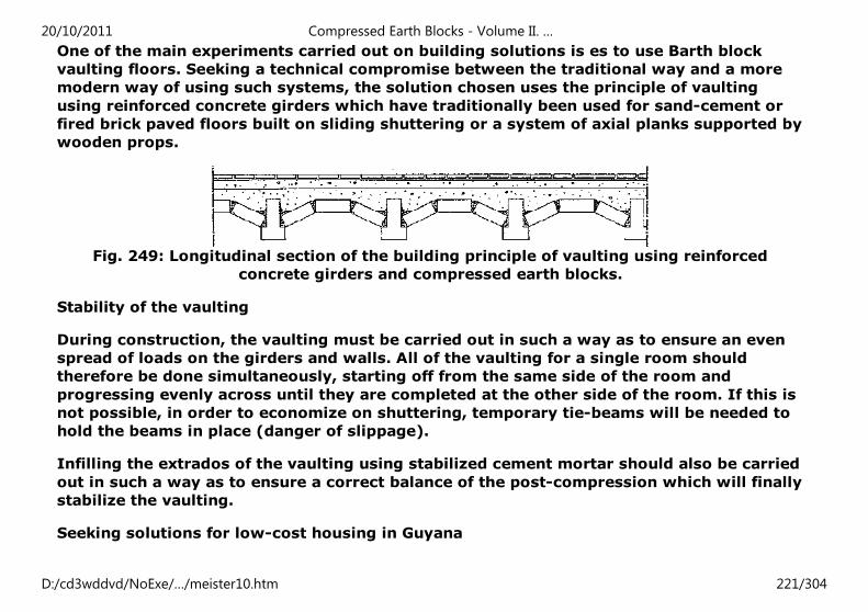
One of the main experiments carried out on building solutions is es to use Barth block
vaulting floors. Seeking a technical compromise between the traditional way and a more
modern way of using such systems, the solution chosen uses the principle of vaulting
using reinforced concrete girders which have traditionally been used for sand-cement or
fired brick paved floors built on sliding shuttering or a system of axial planks supported by
wooden props.
Fig. 249: Longitudinal section of the building principle of vaulting using reinforced
concrete girders and compressed earth blocks.
Stability of the vaulting
During construction, the vaulting must be carried out in such a way as to ensure an even
spread of loads on the girders and walls. All of the vaulting for a single room should
therefore be done simultaneously, starting off from the same side of the room and
progressing evenly across until they are completed at the other side of the room. If this is
not possible, in order to economize on shuttering, temporary tie-beams will be needed to
hold the beams in place (danger of slippage).
Infilling the extrados of the vaulting using stabilized cement mortar should also be carried
out in such a way as to ensure a correct balance of the post-compression which will finally
stabilize the vaulting.
Seeking solutions for low-cost housing in Guyana
20/10/2011 Compressed Earth Blocks - Volume II. …
D:/cd3wddvd/NoExe/…/meister10.htm 221/304
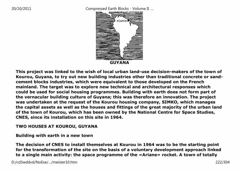
GUYANA
This project was linked to the wish of local urban land-use decision-makers of the town of
Kourou, Guyana, to try out new building industries other than traditional concrete or sand-
cement blocks industries, which were equivalent to those developed on the French
mainland. The target was to explore new technical and architectural responses which
could be used for social housing programmes. Building with earth does not form part of
the vernacular building culture of Guyana; this was therefore an innovation. The project
was undertaken at the request of the Kourou housing company, SIMKO, which manages
the capital assets as well as the houses and fittings of the great majority of the urban land
of the town of Kourou, which has been owned by the National Centre for Space Studies,
CNES, since its installation on this site in 1964.
TWO HOUSES AT KOUROU, GUYANA
Building with earth in a new town
The decision of CNES to install themselves at Kourou in 1964 was to be the starting point
for the transformation of the site on the basis of a voluntary development approach linked
to a single main activity: the space programme of the «Ariane» rocket. A town of totally
20/10/2011 Compressed Earth Blocks - Volume II. …
D:/cd3wddvd/NoExe/…/meister10.htm 222/304
new and modern design was entirely created in a matter of a few years. The great majority
of the housing stock of the town consisted of recently-built houses, the design and
building methods of which met French metropolitan norms and standards. Concrete and
sand-cement blocks dominated the landscape. The very rapid increase in population over
the course of the last twenty-five years, at a very fast rate, contributed to the explosive
growth of Guyana's main urban centres (Cayenne, Kourou, St. Laurent). The more specific
development of the commune of Kourou was confronting very high demand for lost-cost or
very low-cost housing for which the architectural and building solutions being used at the
time were not always economically or qualitatively satisfactory. It was in this context,
that of a new town seeking to improve its response to the problem of low-cost housing,
that this programme of building using compressed earth blocks was situated.
TECHNICAL FEATURES OF THE PROJECT
Programme: two experimental houses built from stabilized compressed earth blocks.
One three bedroom - type T3 - two-storey model with a 56 m² habitable surface area.
One four bedroom - type T4 - single-storey model with a 70 m² habitable surface area.
Owner: Kourou housing company, SIMKO.
Contractor: architects A. Corandi and B. Girard.
Technical and architectural assistance: CRATerre - School of Architecture of Grenoble.
Coordination of site work: P. Huon and S. Dours, building technicians.
Foundations: blinding concrete at the bottom of trenches in compacted ditches and R.C.
ground beam poured in situ.
20/10/2011 Compressed Earth Blocks - Volume II. …
D:/cd3wddvd/NoExe/…/meister10.htm 223/304
Pavement: on compacted sand infill covered with polythene film and 10 cm thick
reinforced concrete with reinforcements alongside the ground beams and interior walls.
Masonry walls: in stabilized earth blocks measuring 29.5 × 14 × 9 cm. Bonding pattern
used giving 14 and 29.5 cm thick walls.
Lintels of openings: shuttered earth block arches.
Ring-beams: reinforced concrete, 10 cm thick, at the top level of the first level. Poured
into an earth block lost formwork. Sloping ring-beam at top of gable walls.
Floors: angelica wood joists anchored into the ring-beam concrete; local wood parquet
floor.
Roof: braced truss structure, with purling, rafters and lintels. Verandah on mixed posts.
Covering in split «wapa» shingles.
Woodwork: in planed red St. Martin wood, anchored into the masonry on wooden blocks
built in with mortar.
Renders: highly diluted sand-cement wash on the exterior earth block walls.
Architectural design of two-storey T3 type house
The design principles of these two experimental houses are in response to the idea of
building a double demonstration using two distinct types of plan: a two-storey type house
and a single-storey type house. Each of these houses, however, meets the norms for
special habitability of low-cost houses built in the urban area of the commune of Kourou.
On the two-storey type house, the principle of a simple, double-slope roof with a high
gable wall is used; this means that the house could in the future be extended on either
20/10/2011 Compressed Earth Blocks - Volume II. …
D:/cd3wddvd/NoExe/…/meister10.htm 224/304
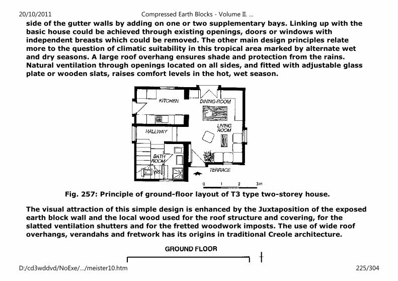
side of the gutter walls by adding on one or two supplementary bays. Linking up with the
basic house could be achieved through existing openings, doors or windows with
independent breasts which could be removed. The other main design principles relate
more to the question of climatic suitability in this tropical area marked by alternate wet
and dry seasons. A large roof overhang ensures shade and protection from the rains.
Natural ventilation through openings located on all sides, and fitted with adjustable glass
plate or wooden slats, raises comfort levels in the hot, wet season.
Fig. 257: Principle of ground-floor layout of T3 type two-storey house.
The visual attraction of this simple design is enhanced by the Juxtaposition of the exposed
earth block wall and the local wood used for the roof structure and covering, for the
slatted ventilation shutters and for the fretted woodwork imposts. The use of wide roof
overhangs, verandahs and fretwork has its origins in traditional Creole architecture.
20/10/2011 Compressed Earth Blocks - Volume II. …
D:/cd3wddvd/NoExe/…/meister10.htm 225/304
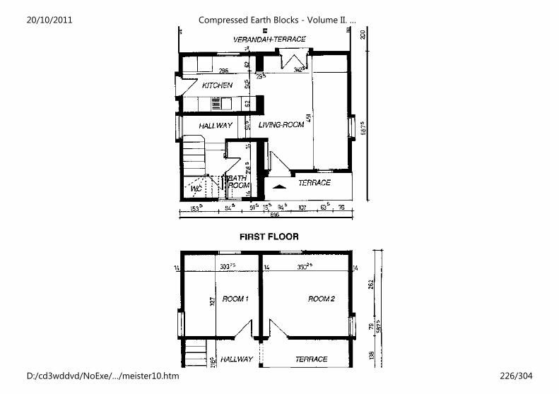
20/10/2011 Compressed Earth Blocks - Volume II. …
D:/cd3wddvd/NoExe/…/meister10.htm 226/304
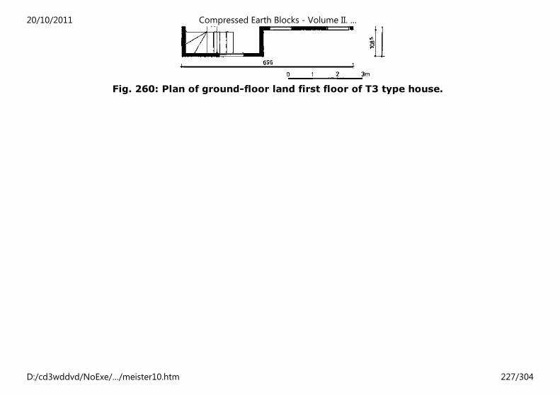
Fig. 260: Plan of ground-floor land first floor of T3 type house.
20/10/2011 Compressed Earth Blocks - Volume II. …
D:/cd3wddvd/NoExe/…/meister10.htm 227/304
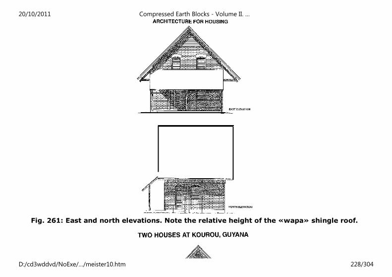
Fig. 261: East and north elevations. Note the relative height of the «wapa» shingle roof.
20/10/2011 Compressed Earth Blocks - Volume II. …
D:/cd3wddvd/NoExe/…/meister10.htm 228/304
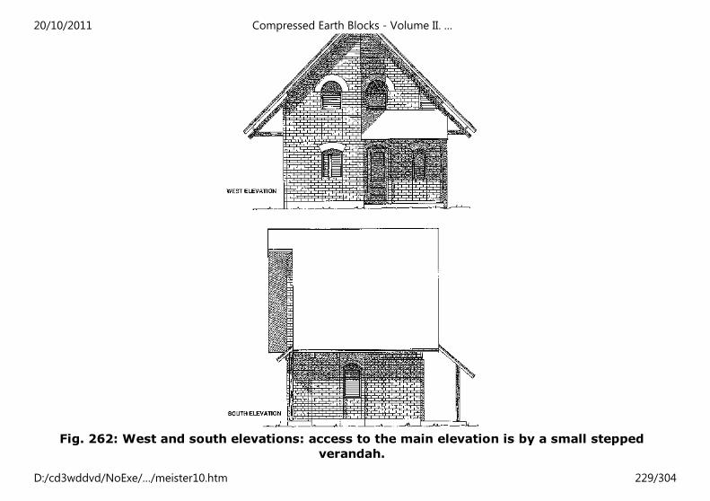
Fig. 262: West and south elevations: access to the main elevation is by a small stepped
verandah.
20/10/2011 Compressed Earth Blocks - Volume II. …
D:/cd3wddvd/NoExe/…/meister10.htm 229/304

20/10/2011 Compressed Earth Blocks - Volume II. …
D:/cd3wddvd/NoExe/…/meister10.htm 230/304
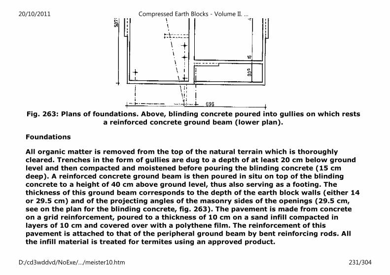
Fig. 263: Plans of foundations. Above, blinding concrete poured into gullies on which rests
a reinforced concrete ground beam (lower plan).
Foundations
All organic matter is removed from the top of the natural terrain which is thoroughly
cleared. Trenches in the form of gullies are dug to a depth of at least 20 cm below ground
level and then compacted and moistened before pouring the blinding concrete (15 cm
deep). A reinforced concrete ground beam is then poured in situ on top of the blinding
concrete to a height of 40 cm above ground level, thus also serving as a footing. The
thickness of this ground beam corresponds to the depth of the earth block walls (either 14
or 29.5 cm) and of the projecting angles of the masonry sides of the openings (29.5 cm,
see on the plan for the blinding concrete, fig. 263). The pavement is made from concrete
on a grid reinforcement, poured to a thickness of 10 cm on a sand infill compacted in
layers of 10 cm and covered over with a polythene film. The reinforcement of this
pavement is attached to that of the peripheral ground beam by bent reinforcing rods. All
the infill material is treated for termites using an approved product.
20/10/2011 Compressed Earth Blocks - Volume II. …
D:/cd3wddvd/NoExe/…/meister10.htm 231/304
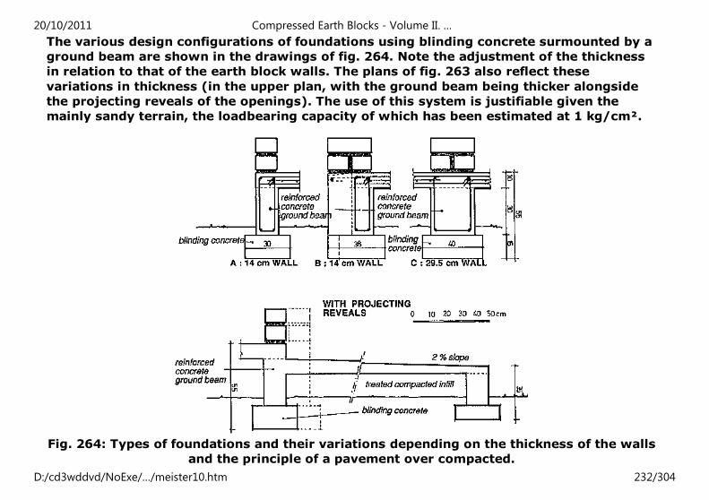
The various design configurations of foundations using blinding concrete surmounted by a
ground beam are shown in the drawings of fig. 264. Note the adjustment of the thickness
in relation to that of the earth block walls. The plans of fig. 263 also reflect these
variations in thickness (in the upper plan, with the ground beam being thicker alongside
the projecting reveals of the openings). The use of this system is justifiable given the
mainly sandy terrain, the loadbearing capacity of which has been estimated at 1 kg/cm².
Fig. 264: Types of foundations and their variations depending on the thickness of the walls
and the principle of a pavement over compacted.
20/10/2011 Compressed Earth Blocks - Volume II. …
D:/cd3wddvd/NoExe/…/meister10.htm 232/304
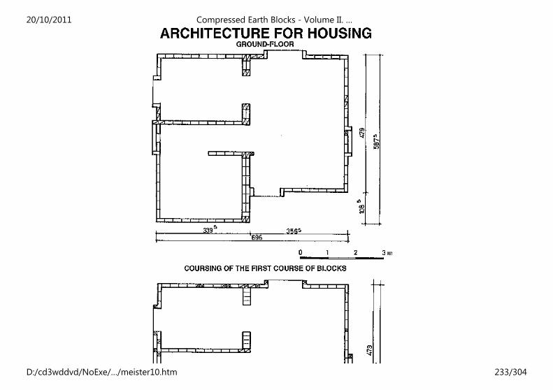
20/10/2011 Compressed Earth Blocks - Volume II. …
D:/cd3wddvd/NoExe/…/meister10.htm 233/304
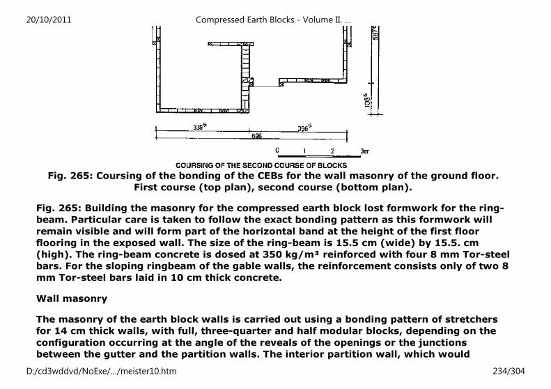
Fig. 265: Coursing of the bonding of the CEBs for the wall masonry of the ground floor.
First course (top plan), second course (bottom plan).
Fig. 265: Building the masonry for the compressed earth block lost formwork for the ring-
beam. Particular care is taken to follow the exact bonding pattern as this formwork will
remain visible and will form part of the horizontal band at the height of the first floor
flooring in the exposed wall. The size of the ring-beam is 15.5 cm (wide) by 15.5. cm
(high). The ring-beam concrete is dosed at 350 kg/m³ reinforced with four 8 mm Tor-steel
bars. For the sloping ringbeam of the gable walls, the reinforcement consists only of two 8
mm Tor-steel bars laid in 10 cm thick concrete.
Wall masonry
The masonry of the earth block walls is carried out using a bonding pattern of stretchers
for 14 cm thick walls, with full, three-quarter and half modular blocks, depending on the
configuration occurring at the angle of the reveals of the openings or the junctions
between the gutter and the partition walls. The interior partition wall, which would
20/10/2011 Compressed Earth Blocks - Volume II. …
D:/cd3wddvd/NoExe/…/meister10.htm 234/304
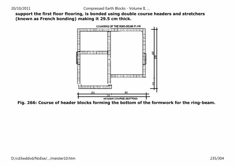
support the first floor flooring, is bonded using double course headers and stretchers
(known as French bonding) making it 29.5 cm thick.
Fig. 266: Course of header blocks forming the bottom of the formwork for the ring-beam.
20/10/2011 Compressed Earth Blocks - Volume II. …
D:/cd3wddvd/NoExe/…/meister10.htm 235/304
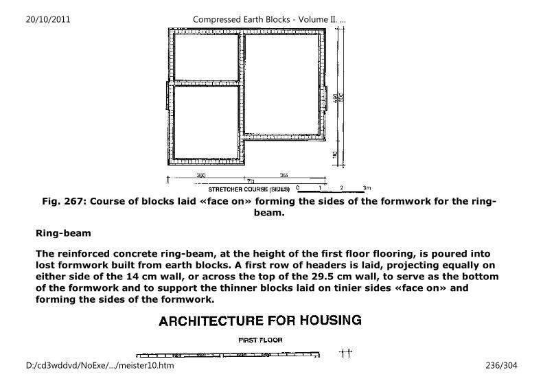
Fig. 267: Course of blocks laid «face on» forming the sides of the formwork for the ring-
beam.
Ring-beam
The reinforced concrete ring-beam, at the height of the first floor flooring, is poured into
lost formwork built from earth blocks. A first row of headers is laid, projecting equally on
either side of the 14 cm wall, or across the top of the 29.5 cm wall, to serve as the bottom
of the formwork and to support the thinner blocks laid on tinier sides «face on» and
forming the sides of the formwork.
20/10/2011 Compressed Earth Blocks - Volume II. …
D:/cd3wddvd/NoExe/…/meister10.htm 236/304
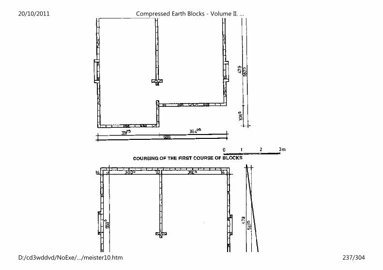
20/10/2011 Compressed Earth Blocks - Volume II. …
D:/cd3wddvd/NoExe/…/meister10.htm 237/304
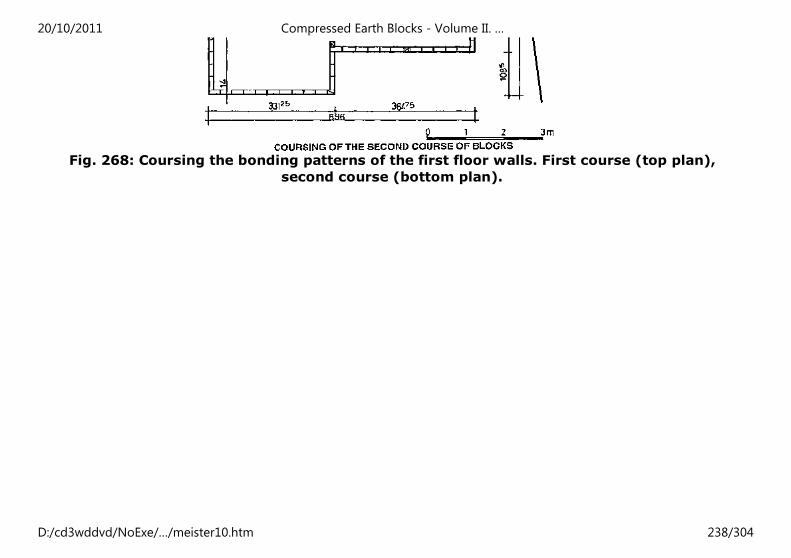
Fig. 268: Coursing the bonding patterns of the first floor walls. First course (top plan),
second course (bottom plan).
20/10/2011 Compressed Earth Blocks - Volume II. …
D:/cd3wddvd/NoExe/…/meister10.htm 238/304
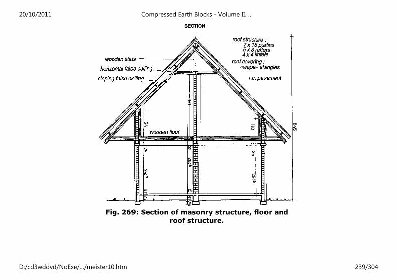
Fig. 269: Section of masonry structure, floor and
roof structure.
20/10/2011 Compressed Earth Blocks - Volume II. …
D:/cd3wddvd/NoExe/…/meister10.htm 239/304
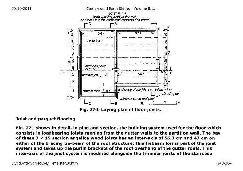
Fig. 270: Laying plan of floor joists.
Joist and parquet flooring
Fig. 271 shows in detail, in plan and section, the building system used for the floor which
consists in loadbearing joists running from the gutter walls to the partition wall. The bay
of these 7 × 15 section angelica wood joists has an inter-axis of 56.7 cm and 47 cm on
either of the bracing tie-beam of the roof structure; this tiebeam forms part of the joist
system and takes up the purlin brackets of the roof overhang of the gutter roofs. This
inter-axis of the joist system is modified alongside the trimmer joists of the staircase
20/10/2011 Compressed Earth Blocks - Volume II. …
D:/cd3wddvd/NoExe/…/meister10.htm 240/304
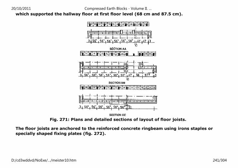
which supported the hallway floor at first floor level (68 cm and 87.5 cm).
Fig. 271: Plans and detailed sections of layout of floor joists.
The floor joists are anchored to the reinforced concrete ringbeam using irons staples or
specially shaped fixing plates (fig. 272).
20/10/2011 Compressed Earth Blocks - Volume II. …
D:/cd3wddvd/NoExe/…/meister10.htm 241/304
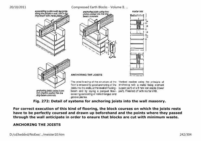
Fig. 272: Detail of systems for anchoring joists into the wall masonry.
For correct execution of this kind of flooring, the block courses on which the joists rests
have to be perfectly coursed and drawn up beforehand and the points where they passed
through the wall anticipate in order to ensure that blocks are cut with minimum waste.
ANCHORING THE JOISTS
20/10/2011 Compressed Earth Blocks - Volume II. …
D:/cd3wddvd/NoExe/…/meister10.htm 242/304
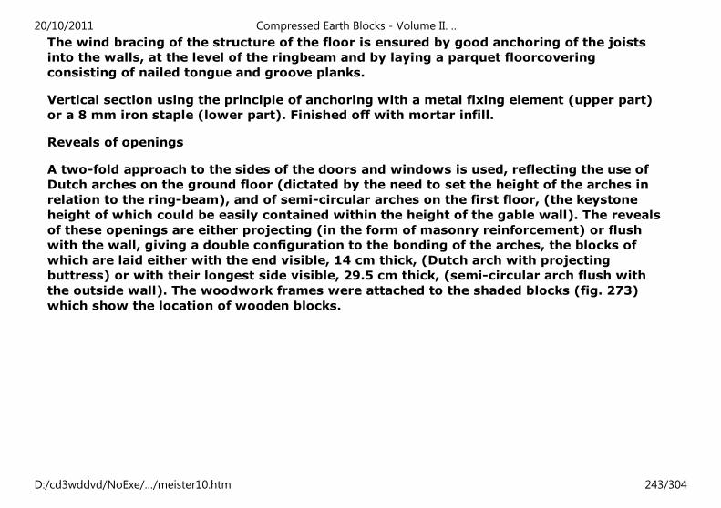
The wind bracing of the structure of the floor is ensured by good anchoring of the joists
into the walls, at the level of the ringbeam and by laying a parquet floorcovering
consisting of nailed tongue and groove planks.
Vertical section using the principle of anchoring with a metal fixing element (upper part)
or a 8 mm iron staple (lower part). Finished off with mortar infill.
Reveals of openings
A two-fold approach to the sides of the doors and windows is used, reflecting the use of
Dutch arches on the ground floor (dictated by the need to set the height of the arches in
relation to the ring-beam), and of semi-circular arches on the first floor, (the keystone
height of which could be easily contained within the height of the gable wall). The reveals
of these openings are either projecting (in the form of masonry reinforcement) or flush
with the wall, giving a double configuration to the bonding of the arches, the blocks of
which are laid either with the end visible, 14 cm thick, (Dutch arch with projecting
buttress) or with their longest side visible, 29.5 cm thick, (semi-circular arch flush with
the outside wall). The woodwork frames were attached to the shaded blocks (fig. 273)
which show the location of wooden blocks.
20/10/2011 Compressed Earth Blocks - Volume II. …
D:/cd3wddvd/NoExe/…/meister10.htm 243/304
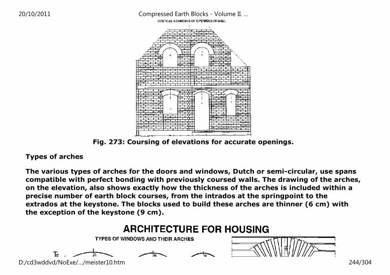
Fig. 273: Coursing of elevations for accurate openings.
Types of arches
The various types of arches for the doors and windows, Dutch or semi-circular, use spans
compatible with perfect bonding with previously coursed walls. The drawing of the arches,
on the elevation, also shows exactly how the thickness of the arches is included within a
precise number of earth block courses, from the intrados at the springpoint to the
extrados at the keystone. The blocks used to build these arches are thinner (6 cm) with
the exception of the keystone (9 cm).
20/10/2011 Compressed Earth Blocks - Volume II. …
D:/cd3wddvd/NoExe/…/meister10.htm 244/304
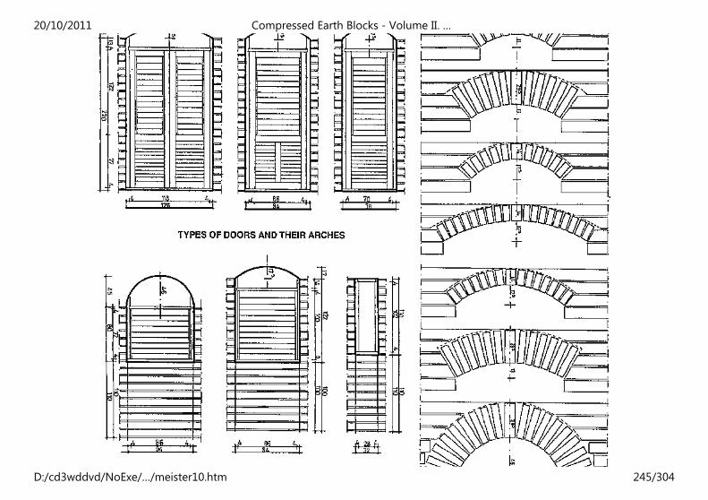
20/10/2011 Compressed Earth Blocks - Volume II. …
D:/cd3wddvd/NoExe/…/meister10.htm 245/304
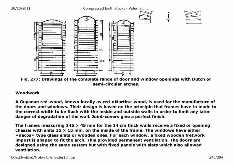
Fig. 277: Drawings of the complete range of door and window openings with Dutch or
semi-circular arches.
Woodwork
A Guyanan red-wood, known locally as red «Martin» wood, is used for the manufacture of
the doors and windows. Their design is based on the principle that frames have to made to
the correct width to be flush with the inside and outside walls in order to limit any later
danger of degradation of the wall. Joint-covers give a perfect finish.
The frames measuring 145 × 45 mm for the 14 cm thick walls receive a fixed or opening
chassis with slats 35 × 15 mm, on the inside of the frame. The windows have either
«nacos» type glass slats or wooden ones. For each window, a fixed wooden fretwork
impost is shaped to fit the arch. This provided permanent ventilation. The doors are
designed using the same system but with fixed panels with slats which also allowed
ventilation.
20/10/2011 Compressed Earth Blocks - Volume II. …
D:/cd3wddvd/NoExe/…/meister10.htm 246/304
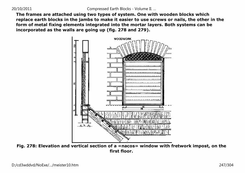
The frames are attached using two types of system. One with wooden blocks which
replace earth blocks in the jambs to make it easier to use screws or nails, the other in the
form of metal fixing elements integrated into the mortar layers. Both systems can be
incorporated as the walls are going up (fig. 278 and 279).
Fig. 278: Elevation and vertical section of a «nacos» window with fretwork impost, on the
first floor.
20/10/2011 Compressed Earth Blocks - Volume II. …
D:/cd3wddvd/NoExe/…/meister10.htm 247/304
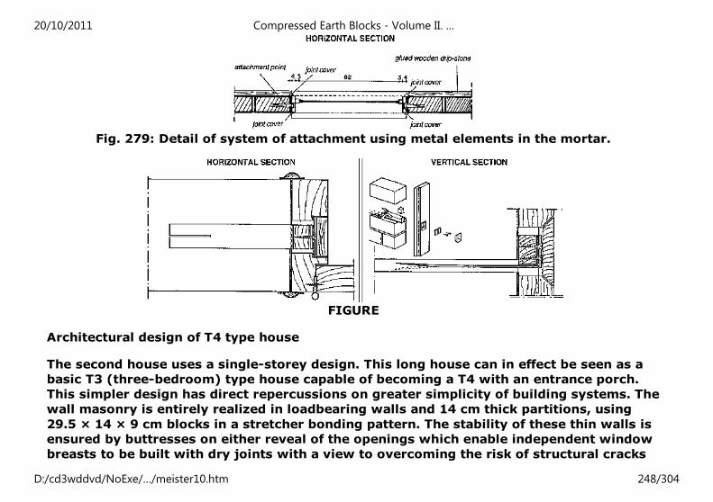
Fig. 279: Detail of system of attachment using metal elements in the mortar.
FIGURE
Architectural design of T4 type house
The second house uses a single-storey design. This long house can in effect be seen as a
basic T3 (three-bedroom) type house capable of becoming a T4 with an entrance porch.
This simpler design has direct repercussions on greater simplicity of building systems. The
wall masonry is entirely realized in loadbearing walls and 14 cm thick partitions, using
29.5 × 14 × 9 cm blocks in a stretcher bonding pattern. The stability of these thin walls is
ensured by buttresses on either reveal of the openings which enable independent window
breasts to be built with dry joints with a view to overcoming the risk of structural cracks
20/10/2011 Compressed Earth Blocks - Volume II. …
D:/cd3wddvd/NoExe/…/meister10.htm 248/304
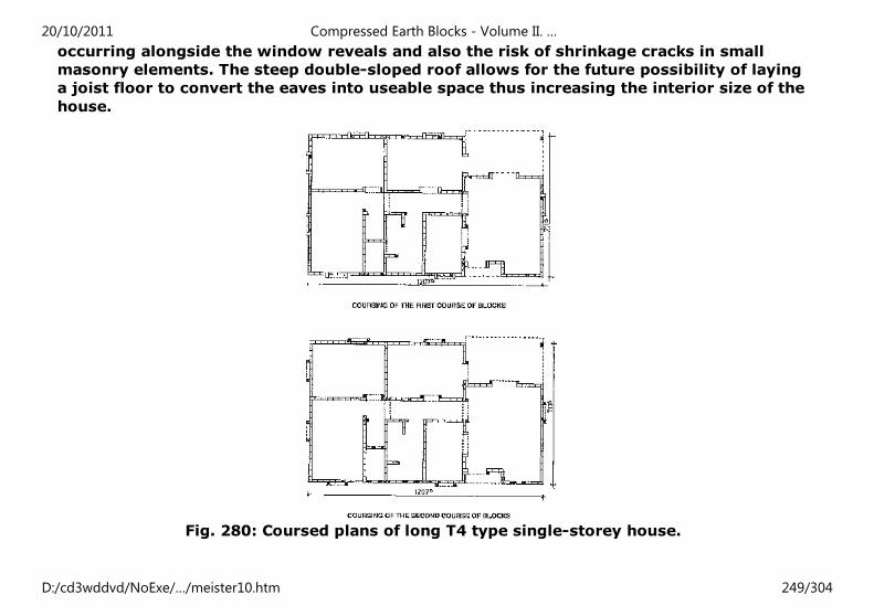
occurring alongside the window reveals and also the risk of shrinkage cracks in small
masonry elements. The steep double-sloped roof allows for the future possibility of laying
a joist floor to convert the eaves into useable space thus increasing the interior size of the
house.
Fig. 280: Coursed plans of long T4 type single-storey house.
20/10/2011 Compressed Earth Blocks - Volume II. …
D:/cd3wddvd/NoExe/…/meister10.htm 249/304
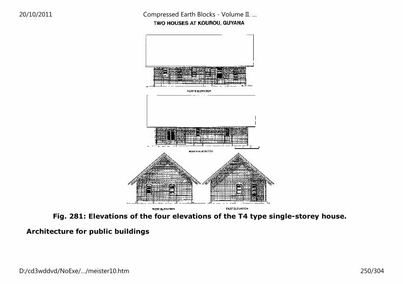
Fig. 281: Elevations of the four elevations of the T4 type single-storey house.
Architecture for public buildings
20/10/2011 Compressed Earth Blocks - Volume II. …
D:/cd3wddvd/NoExe/…/meister10.htm 250/304
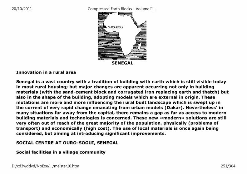
SENEGAL
Innovation in a rural area
Senegal is a vast country with a tradition of building with earth which is still visible today
in most rural housing; but major changes are apparent occurring not only in building
materials (with the sand-cement block and corrugated iron replacing earth and thatch) but
also in the shape of the building, adopting models which are external in origin. These
mutations are more and more influencing the rural built landscape which is swept up in
the current of very rapid change emanating from urban models (Dakar). Nevertheless' in
many situations far away from the capital, there remains a gap as far as access to modern
building materials and technologies is concerned. These new «modern» solutions are still
very often out of reach of the great majority of the population, physically (problems of
transport) and economically (high cost). The use of local materials is once again being
considered, but aiming at introducing significant improvements.
SOCIAL CENTRE AT OURO-SOGUI, SENEGAL
Social facilities in a village community
20/10/2011 Compressed Earth Blocks - Volume II. …
D:/cd3wddvd/NoExe/…/meister10.htm 251/304
During the year 1987-88, the village community of Ouro-Sogui, a small town located in
north-east Senegal, not far from the Mauritanian frontier and approximately 500 km from
Dakar, designed a project for a social centre with guest house facilities. Anxious to use
building and architectural solutions which would remain accessible whilst introducing
significant improvements to traditional practices, the village decided to opt for using the
compressed earth block which bridged the gap between traditional and modern building.
This approach emerged through a link maintained between the village community and
expatriate French residents who were able to obtain information about recent
developments in building with earth. The Association for the development of Ouro-Sogui
(ADO) contacted the municipality of the town of Valence (in Drome, France), which found
the project attractive and rapidly responded to the appeal of Senegalese community by
creating it own association «Drome Ouro-Sogui». It is in the context of these associations
that this small bilateral cooperation project took place. The project requested the help of
CRATerre-EAG and resulted in a combined construction, production and training site for
the building of the social centre and guest house of Ouro-Sogui.
TECHNICAL FEATURES OF THE PROJECT
Social centre and guest house: total habitable surface area: 280 m², achieved in three
work phases.
- First phase: pilot building and training phase whilst building the guest house: 44 m² of
habitable surface area.
- Second phase: first workshop block: 83 m² of habitable surface area.
-Third phase: second, larger workshop block, meeting room and dry latrine facilities: 152
m² of habitable surface area.
Implementation: Association for the development of Ouro-Sogui (ADO)
20/10/2011 Compressed Earth Blocks - Volume II. …
D:/cd3wddvd/NoExe/…/meister10.htm 252/304
With the help of the Drome Ouro-Sogui association (ADOS) and of CRATerre-EAG.
Construction: local masons and labour.
Foundations: Cyclopean concrete poured into trenches dug in previously compacted
gullies: lateritic rubble stones and mortar dosed at 150 kg/m³.
Footings: three courses of compressed earth blocks stabilized at 8% and laid in an earth
mortar stabilized at 10%.
Wall masonry:
- External walls: compressed earth blocks stabilized at 4%, laid in earth mortar stabilized
at 6%. Block dimensions: 29.5 × 14 × 9 cm. Walls built 29.5 cm thick using a header and
stretcher bonding pattern.
- Internal walls and partitions: in compressed earth blocks (as for external walls) but 14
cm thick using a stretcher bonding pattern.
Ring-beam: made from wood, using 27 mm local hard red-wood planks. Wood treated
against insect and termite attack.
Roof structure: made from wood, using 22 cm wide local hard red-wood planks. Rafters
made from planks previously sawn lengthways into 11 cm widths and nailed into place. 6
× 8 mm purling. Gable-end rafters fixed to the wooden ring-beam. 22 cm local hard red-
wood edging planks, sawn down into 11 cm widths.
Roof covering: 23 mm galvanized corrugated iron sheeting 200 x80 cm.
False ceiling: woven organic material (e.g. reeds or palmyra branches).
20/10/2011 Compressed Earth Blocks - Volume II. …
D:/cd3wddvd/NoExe/…/meister10.htm 253/304
Architectural design
For reasons linked to the introduction of a new building material and new building
techniques, combined with the need for an overall cost which remains within a cheap and
accessible range, the architectural design of the project choses a simple approach. In
addition, on-site training as well as the time-tabling of the project in several phases make
it vital to consider building approaches which would be easily assimilated and
reproduceable by the local population. The building and architectural concept of the
project was tried out during the building of the guest house. This consisted in a double
bay system, with a covered verandah, the longest sides of which correspond to the
direction in which the rafters of the roof structure are laid, suggesting the principle of
future extensions lengthways by adding further bays. Only the masonry of the peripheral
walls is loadbearing and supports the roof rafters, the interior walls serving only to divide
off spaces. Buttresses on the outside elevations help to improve the stability of the walls
and to take up the roof rafters using braced double-legged brackets. For later phases of
the building, the same building and architectural solutions were adopted, which ensured
good quality workmanship after the first phase of experimentation, of training and of
acquisition of knowledge and skills on the part of the local population.
20/10/2011 Compressed Earth Blocks - Volume II. …
D:/cd3wddvd/NoExe/…/meister10.htm 254/304
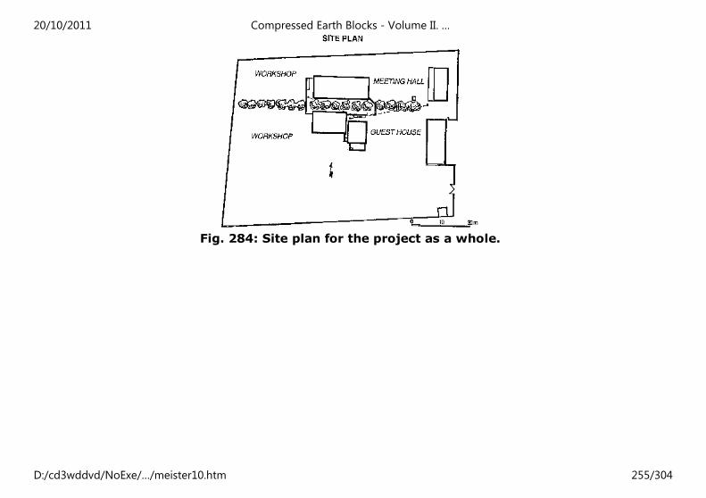
Fig. 284: Site plan for the project as a whole.
20/10/2011 Compressed Earth Blocks - Volume II. …
D:/cd3wddvd/NoExe/…/meister10.htm 255/304
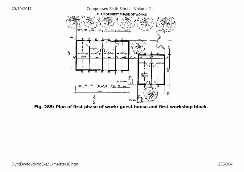
Fig. 285: Plan of first phase of work: guest house and first workshop block.
20/10/2011 Compressed Earth Blocks - Volume II. …
D:/cd3wddvd/NoExe/…/meister10.htm 256/304
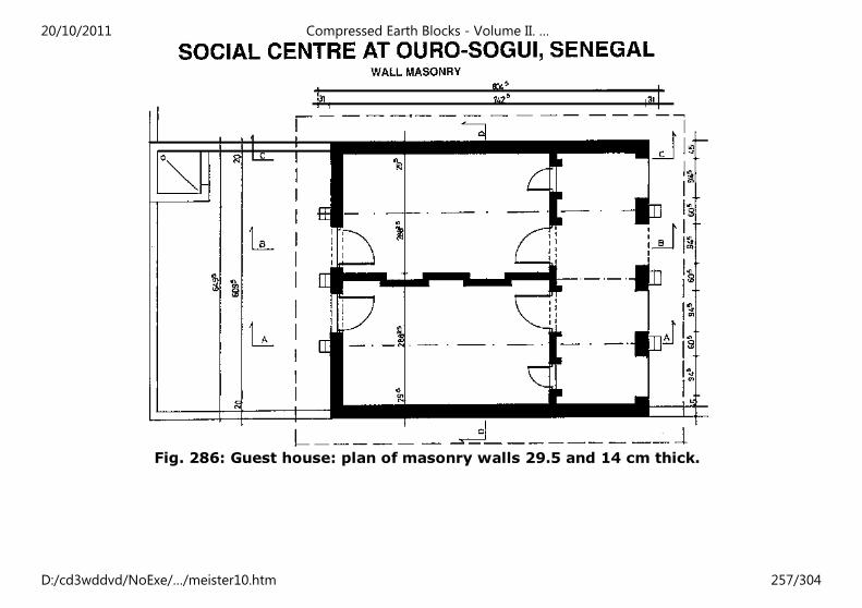
Fig. 286: Guest house: plan of masonry walls 29.5 and 14 cm thick.
20/10/2011 Compressed Earth Blocks - Volume II. …
D:/cd3wddvd/NoExe/…/meister10.htm 257/304
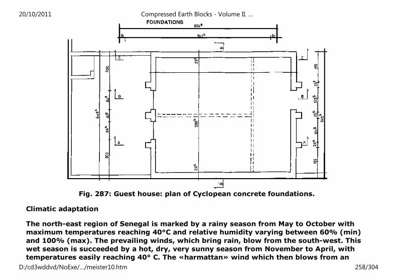
Fig. 287: Guest house: plan of Cyclopean concrete foundations.
Climatic adaptation
The north-east region of Senegal is marked by a rainy season from May to October with
maximum temperatures reaching 40°C and relative humidity varying between 60% (min)
and 100% (max). The prevailing winds, which bring rain, blow from the south-west. This
wet season is succeeded by a hot, dry, very sunny season from November to April, with
temperatures easily reaching 40° C. The «harmattan» wind which then blows from an
20/10/2011 Compressed Earth Blocks - Volume II. …
D:/cd3wddvd/NoExe/…/meister10.htm 258/304
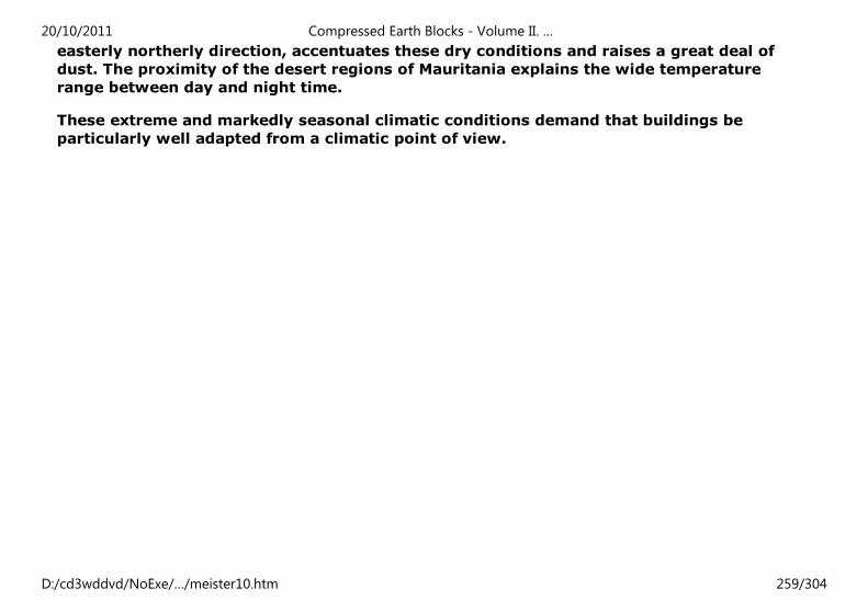
easterly northerly direction, accentuates these dry conditions and raises a great deal of
dust. The proximity of the desert regions of Mauritania explains the wide temperature
range between day and night time.
These extreme and markedly seasonal climatic conditions demand that buildings be
particularly well adapted from a climatic point of view.
20/10/2011 Compressed Earth Blocks - Volume II. …
D:/cd3wddvd/NoExe/…/meister10.htm 259/304
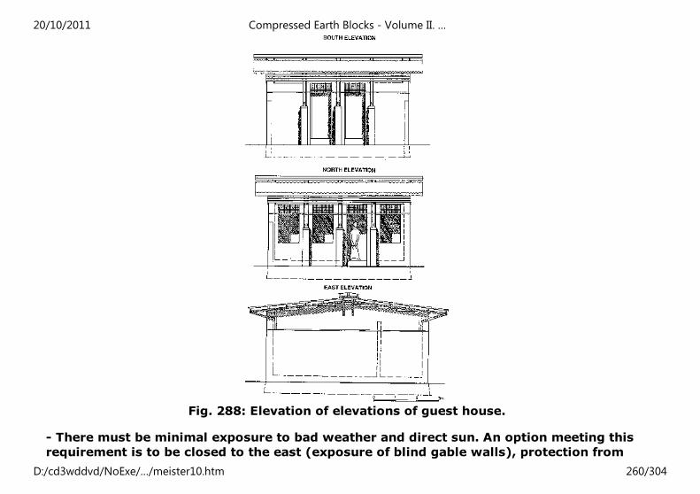
Fig. 288: Elevation of elevations of guest house.
- There must be minimal exposure to bad weather and direct sun. An option meeting this
requirement is to be closed to the east (exposure of blind gable walls), protection from
20/10/2011 Compressed Earth Blocks - Volume II. …
D:/cd3wddvd/NoExe/…/meister10.htm 260/304
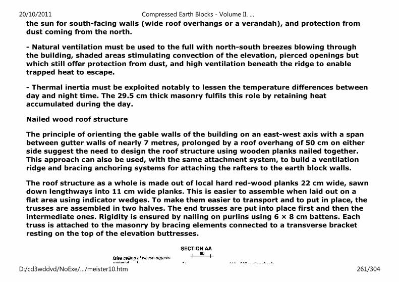
the sun for south-facing walls (wide roof overhangs or a verandah), and protection from
dust coming from the north.
- Natural ventilation must be used to the full with north-south breezes blowing through
the building, shaded areas stimulating convection of the elevation, pierced openings but
which still offer protection from dust, and high ventilation beneath the ridge to enable
trapped heat to escape.
- Thermal inertia must be exploited notably to lessen the temperature differences between
day and night time. The 29.5 cm thick masonry fulfils this role by retaining heat
accumulated during the day.
Nailed wood roof structure
The principle of orienting the gable walls of the building on an east-west axis with a span
between gutter walls of nearly 7 metres, prolonged by a roof overhang of 50 cm on either
side suggest the need to design the roof structure using wooden planks nailed together.
This approach can also be used, with the same attachment system, to build a ventilation
ridge and bracing anchoring systems for attaching the rafters to the earth block walls.
The roof structure as a whole is made out of local hard red-wood planks 22 cm wide, sawn
down lengthways into 11 cm wide planks. This is easier to assemble when laid out on a
flat area using indicator wedges. To make them easier to transport and to put in place, the
trusses are assembled in two halves. The end trusses are put into place first and then the
intermediate ones. Rigidity is ensured by nailing on purlins using 6 × 8 cm battens. Each
truss is attached to the masonry by bracing elements connected to a transverse bracket
resting on the top of the elevation buttresses.
20/10/2011 Compressed Earth Blocks - Volume II. …
D:/cd3wddvd/NoExe/…/meister10.htm 261/304
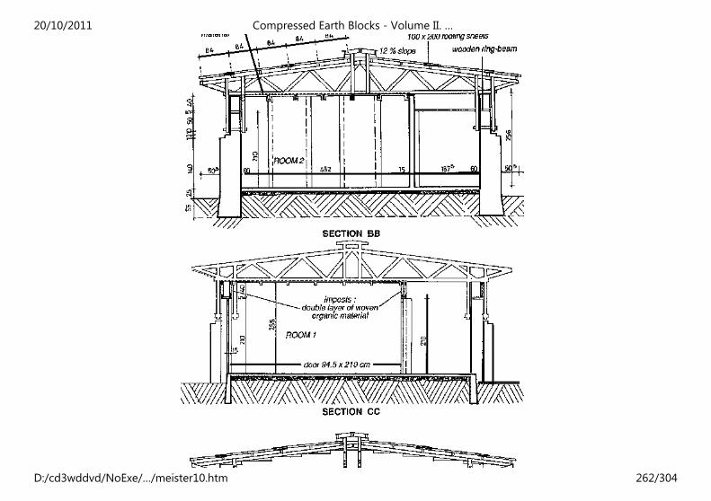
20/10/2011 Compressed Earth Blocks - Volume II. …
D:/cd3wddvd/NoExe/…/meister10.htm 262/304
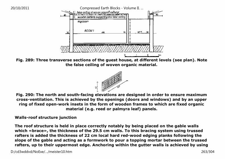
Fig. 289: Three transverse sections of the guest house, at different levels (see plan). Note
the false ceiling of woven organic material.
Fig. 290: The north and south-facing elevations are designed in order to ensure maximum
cross-ventilation. This is achieved by the openings (doors and windows) and by an upper
ring of fixed open-work insets in the form of wooden frames to which are fixed organic
material (e.g. reed or palmyra leaf) panels.
Walls-roof structure junction
The roof structure is held in place correctly notably by being placed on the gable walls
which «brace», the thickness of the 29.5 cm walls. To this bracing system using trussed
rafters is added the thickness of 22 cm local hard red-wood edging planks following the
slope of the gable and acting as a formwork to pour a topping mortar between the trussed
rafters, up to their uppermost edge. Anchoring within the gutter walls is achieved by using
20/10/2011 Compressed Earth Blocks - Volume II. …
D:/cd3wddvd/NoExe/…/meister10.htm 263/304
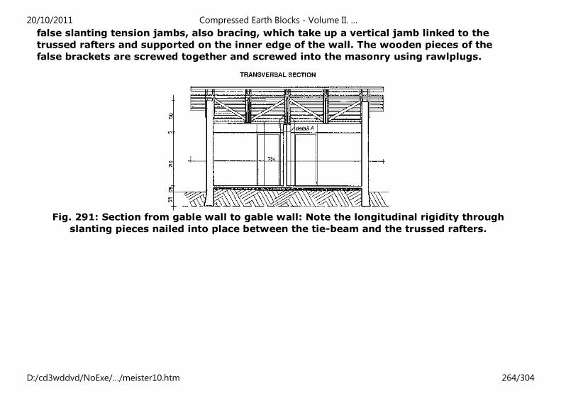
false slanting tension jambs, also bracing, which take up a vertical jamb linked to the
trussed rafters and supported on the inner edge of the wall. The wooden pieces of the
false brackets are screwed together and screwed into the masonry using rawlplugs.
Fig. 291: Section from gable wall to gable wall: Note the longitudinal rigidity through
slanting pieces nailed into place between the tie-beam and the trussed rafters.
20/10/2011 Compressed Earth Blocks - Volume II. …
D:/cd3wddvd/NoExe/…/meister10.htm 264/304
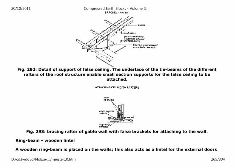
Fig. 292: Detail of support of false ceiling. The underface of the tie-beams of the different
rafters of the roof structure enable small section supports for the false ceiling to be
attached.
Fig. 293: bracing rafter of gable wall with false brackets for attaching to the wall.
Ring-beam - wooden lintel
A wooden ring-beam is placed on the walls; this also acts as a lintel for the external doors
20/10/2011 Compressed Earth Blocks - Volume II. …
D:/cd3wddvd/NoExe/…/meister10.htm 265/304
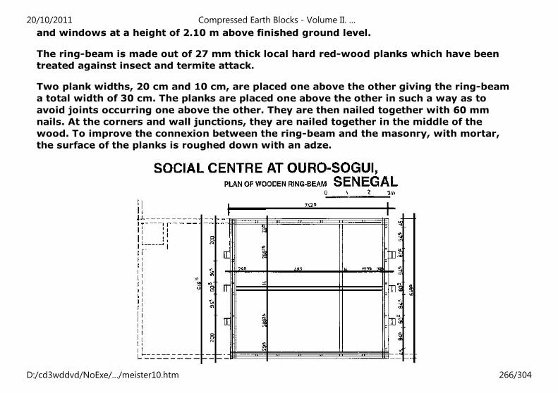
and windows at a height of 2.10 m above finished ground level.
The ring-beam is made out of 27 mm thick local hard red-wood planks which have been
treated against insect and termite attack.
Two plank widths, 20 cm and 10 cm, are placed one above the other giving the ring-beam
a total width of 30 cm. The planks are placed one above the other in such a way as to
avoid joints occurring one above the other. They are then nailed together with 60 mm
nails. At the corners and wall junctions, they are nailed together in the middle of the
wood. To improve the connexion between the ring-beam and the masonry, with mortar,
the surface of the planks is roughed down with an adze.
20/10/2011 Compressed Earth Blocks - Volume II. …
D:/cd3wddvd/NoExe/…/meister10.htm 266/304
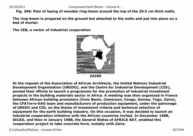
Fig. 296: Plan of laying of wooden ring-beam around the top of the 29.5 cm thick walls.
The ring-beam is prepared on the ground but attached to the walls and put into place on a
bed of mortar.
The CEB, a vector of industrial cooperation
ZAIRE
At the request of the Association of African Architects, the United Nations Industrial
Development Organisation (UNIDO), and the Centre for Industrial Development (CID),
pooled their efforts to launch a programme for the promotion of industrial investment
projects in the building materials sector in Africa. A meeting was then organized in France
between African building promoters (from Benin, Cameroon, Congo, Guinea, Togo, Zaire),
the CFATerre-EAG team and manufacturers of production equipment, under the patronage
of UNIDO and CID, on the theme of investment criteria and technical selection of
equipment for the earth building industry. On this occasion, it was decided to launch an
industrial cooperation initiative with the African countries invited. In December 1988,
SICAD, and then in January 1988, the General States of AFRICA BAT, enabled this
cooperation project to take concrete form, notably with Zaire.
20/10/2011 Compressed Earth Blocks - Volume II. …
D:/cd3wddvd/NoExe/…/meister10.htm 267/304
A SCHOOL IN KINSHASA, ZAIRE
Compressed earth block construction at the service of small contractor promotion
In Zaire, there is clear evidence of a significant deterioration in the national built heritage,
in both rural and urban contexts where living conditions are often very precarious. To this
evidence can be added that of an increase in the costs of building materials which are
increasingly inaccessible to the population. The lack of foreign currency to encourage the
importation of building materials or local investment limits the possibility of industrial
development in the building sector. Faced with this situation, the state of Zaire has
launched a national policy for the promotion of small enterprises with good job-creation
potential, notably in rural areas. This policy also aims to mobilize the wide-scale use of
low-cost building materials and technologies requiring little capital investment. With this
in mind, consideration has been given to transferring compressed earth block technology,
at a decentralized level, to small contractors and local communities. Nevertheless, such a
transfer could not be envisaged without a preliminary phase of information and
technological training, in aspects of both production and construction. This then was the
aim of this pilot project for a school in Kinshasa, in the context of a joint programme run
by UNIDO/CID/Wallone region/CRATerre-EAG, together with 10 Zairian contractors, on
the «Promotion of industrial cooperation in the building materials sector».
TECHNICAL FEATURES OF THE PROJECT
School project, combining production, training and site work on the production of earth
blocks (training in a brickworks), with the design and construction of a demonstration
building.
Project implemented with the support of: UNDP, the Department of Public Works,
Urbanism and Housing of Zaire, the Mama Mobutu Foundation and Appro-Techno.
20/10/2011 Compressed Earth Blocks - Volume II. …
D:/cd3wddvd/NoExe/…/meister10.htm 268/304
In collaboration with: ANEZA, OPEZ and SOFIDE.
With the participation of the following companies: EGEDEZA, GTAC, LOGEC, FINDATION,
MONY, NZOLANTIMA, LA SIDELA, TRAGEMA-ETAZ, and the following NGOs: ECZ and the
Salvation Army.
Building: neighbourhood school consisting in one 52 m² classroom.
Foundations: Reinforced concrete with peripheral ground beams, on a rubble infill,
crushed and tamped.
Wall masonry: compressed earth blocks measuring 29.5 × 14 × 9 cm. Walls 29.5 cm thick,
using a header and stretcher bonding pattern until the 7th course, then 14 cm thick until
the top edge of the wall (see coursing plans).
Roof structure: central wooden truss with trussed rafter and bracing tie-beams. Exterior
prolongation with overhang brackets for the roof overhang and small lateral porches. Roof
covering: galvanized corrugated iron sheeting.
Architectural design
The pilot building undertaken in Kinshasa was the first phase of the building of a much
larger number of schools. The site plan (fig. 301) shows the layout of a group of four
classroom modules designed using the same building and architectural principles as
module 1, which was built during the pilot phase. To this group of classrooms is added an
administrative and service building which repeat the main features of the classrooms,
whilst using a larger, tripped roof. The building principles used by the project are
designed to be easy for the «trainee» enterprises to build them, whilst at the same time
demonstrating a configuration which could be used to implement various project designs.
The 29.5 and 14cm thick masonry walls, using vertical stiffening in the form of buttresses
20/10/2011 Compressed Earth Blocks - Volume II. …
D:/cd3wddvd/NoExe/…/meister10.htm 269/304
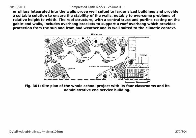
or pillars integrated into the walls prove well suited to larger sized buildings and provide
a suitable solution to ensure the stability of the walls, notably to overcome problems of
relative height to width. The roof structure, with a central truss and purlins resting on the
gable-end walls, includes overhang brackets to support a roof overhang which provides
protection from the sun and from bad weather and is well suited to the climatic context.
Fig. 301: Site plan of the whole school project with its four classrooms and its
administrative end service building.
20/10/2011 Compressed Earth Blocks - Volume II. …
D:/cd3wddvd/NoExe/…/meister10.htm 270/304
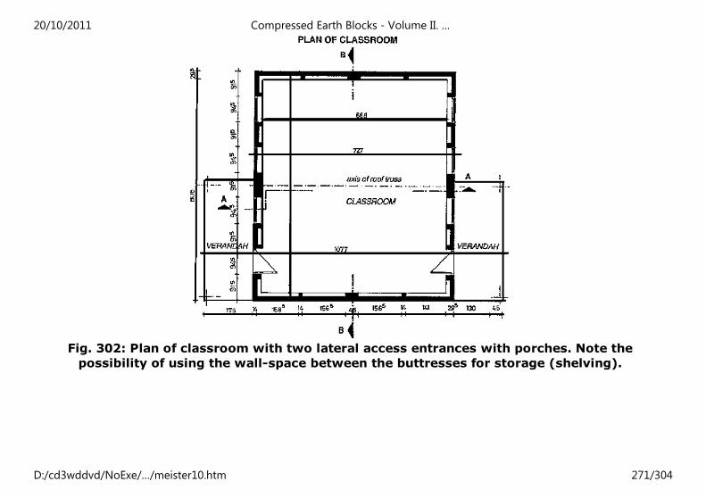
Fig. 302: Plan of classroom with two lateral access entrances with porches. Note the
possibility of using the wall-space between the buttresses for storage (shelving).
20/10/2011 Compressed Earth Blocks - Volume II. …
D:/cd3wddvd/NoExe/…/meister10.htm 271/304
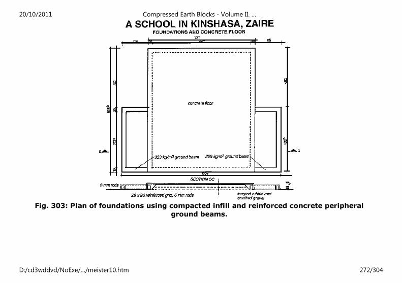
Fig. 303: Plan of foundations using compacted infill and reinforced concrete peripheral
ground beams.
20/10/2011 Compressed Earth Blocks - Volume II. …
D:/cd3wddvd/NoExe/…/meister10.htm 272/304
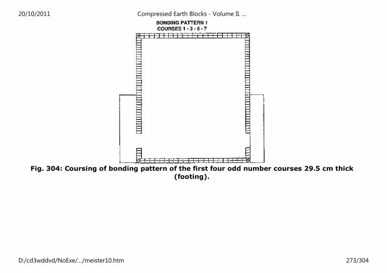
Fig. 304: Coursing of bonding pattern of the first four odd number courses 29.5 cm thick
(footing).
20/10/2011 Compressed Earth Blocks - Volume II. …
D:/cd3wddvd/NoExe/…/meister10.htm 273/304
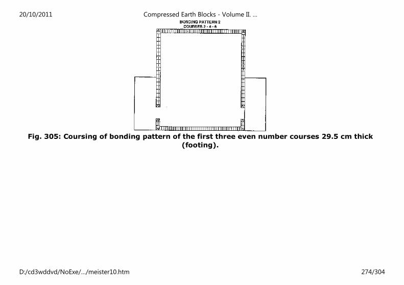
Fig. 305: Coursing of bonding pattern of the first three even number courses 29.5 cm thick
(footing).
20/10/2011 Compressed Earth Blocks - Volume II. …
D:/cd3wddvd/NoExe/…/meister10.htm 274/304
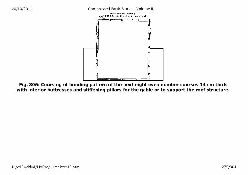
Fig. 306: Coursing of bonding pattern of the next eight even number courses 14 cm thick
with interior buttresses and stiffening pillars for the gable or to support the roof structure.
20/10/2011 Compressed Earth Blocks - Volume II. …
D:/cd3wddvd/NoExe/…/meister10.htm 275/304
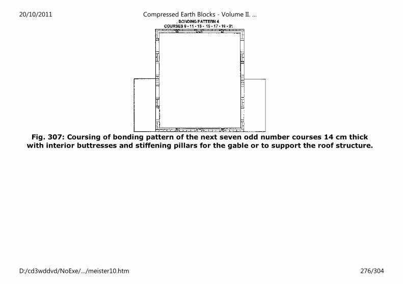
Fig. 307: Coursing of bonding pattern of the next seven odd number courses 14 cm thick
with interior buttresses and stiffening pillars for the gable or to support the roof structure.
20/10/2011 Compressed Earth Blocks - Volume II. …
D:/cd3wddvd/NoExe/…/meister10.htm 276/304
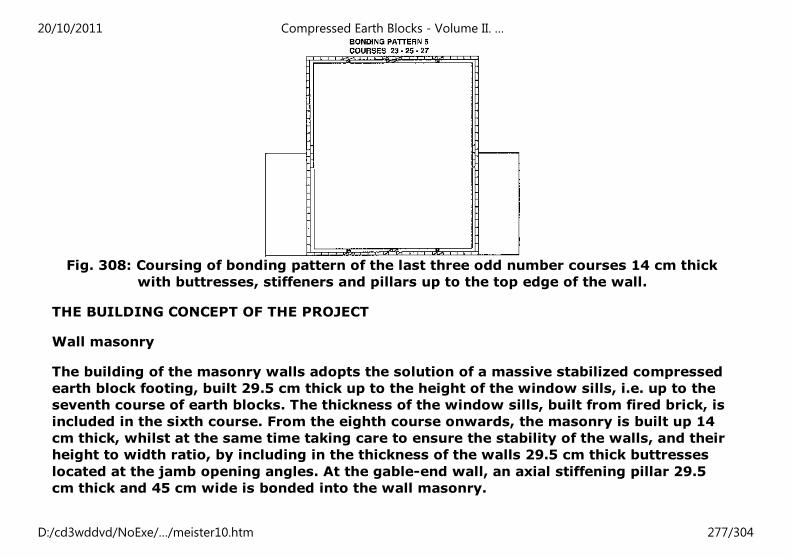
Fig. 308: Coursing of bonding pattern of the last three odd number courses 14 cm thick
with buttresses, stiffeners and pillars up to the top edge of the wall.
THE BUILDING CONCEPT OF THE PROJECT
Wall masonry
The building of the masonry walls adopts the solution of a massive stabilized compressed
earth block footing, built 29.5 cm thick up to the height of the window sills, i.e. up to the
seventh course of earth blocks. The thickness of the window sills, built from fired brick, is
included in the sixth course. From the eighth course onwards, the masonry is built up 14
cm thick, whilst at the same time taking care to ensure the stability of the walls, and their
height to width ratio, by including in the thickness of the walls 29.5 cm thick buttresses
located at the jamb opening angles. At the gable-end wall, an axial stiffening pillar 29.5
cm thick and 45 cm wide is bonded into the wall masonry.
20/10/2011 Compressed Earth Blocks - Volume II. …
D:/cd3wddvd/NoExe/…/meister10.htm 277/304
Finally, two massive pillars, 29.5 cm thick and 91.5 cm wide, are also bonded into the
gutter walls in the median transverse axis; these are designed to receive the bracing tie-
beam of the roof structure.
This stability of the walls is also reinforced by using a peripheral ring-beam, poured at the
height of the twenty-third course of blocks. The concrete for this ring-beam is poured into
special compressed earth blocks, with longitudinal grooves in which lie a single layer of
rods.
The classroom is extended in both directions from the gutter walls, on the classroom
access side, by two small open verandahs, which are covered by a direct prolongation of
the roof structure beyond the lower edges of the roof, thanks to a simple false console
system, anchored into the masonry wall. These details will later be precisely defined.
20/10/2011 Compressed Earth Blocks - Volume II. …
D:/cd3wddvd/NoExe/…/meister10.htm 278/304
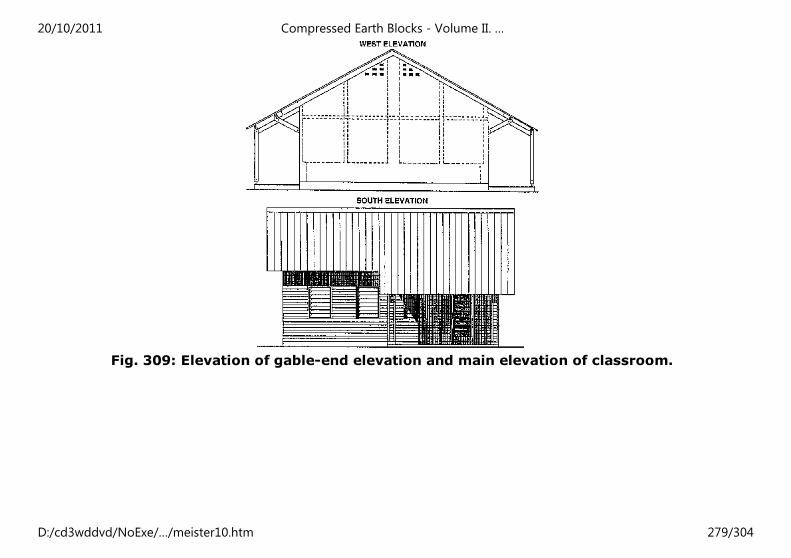
Fig. 309: Elevation of gable-end elevation and main elevation of classroom.
20/10/2011 Compressed Earth Blocks - Volume II. …
D:/cd3wddvd/NoExe/…/meister10.htm 279/304
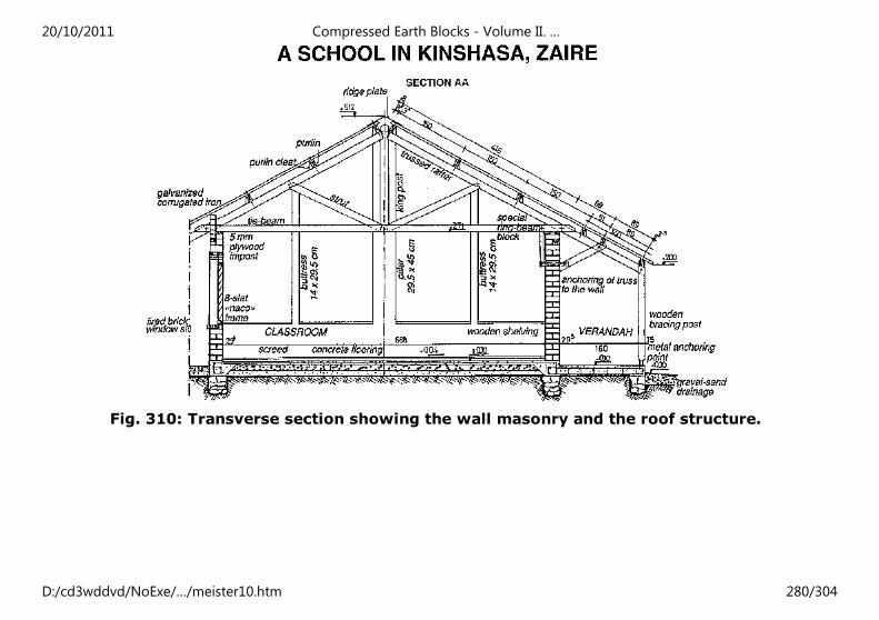
Fig. 310: Transverse section showing the wall masonry and the roof structure.
20/10/2011 Compressed Earth Blocks - Volume II. …
D:/cd3wddvd/NoExe/…/meister10.htm 280/304
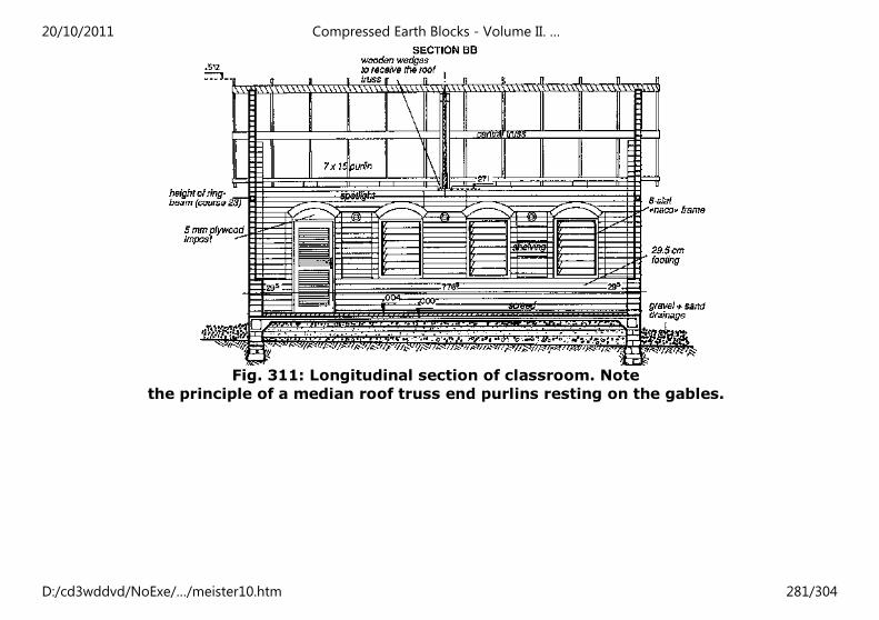
Fig. 311: Longitudinal section of classroom. Note
the principle of a median roof truss end purlins resting on the gables.
20/10/2011 Compressed Earth Blocks - Volume II. …
D:/cd3wddvd/NoExe/…/meister10.htm 281/304
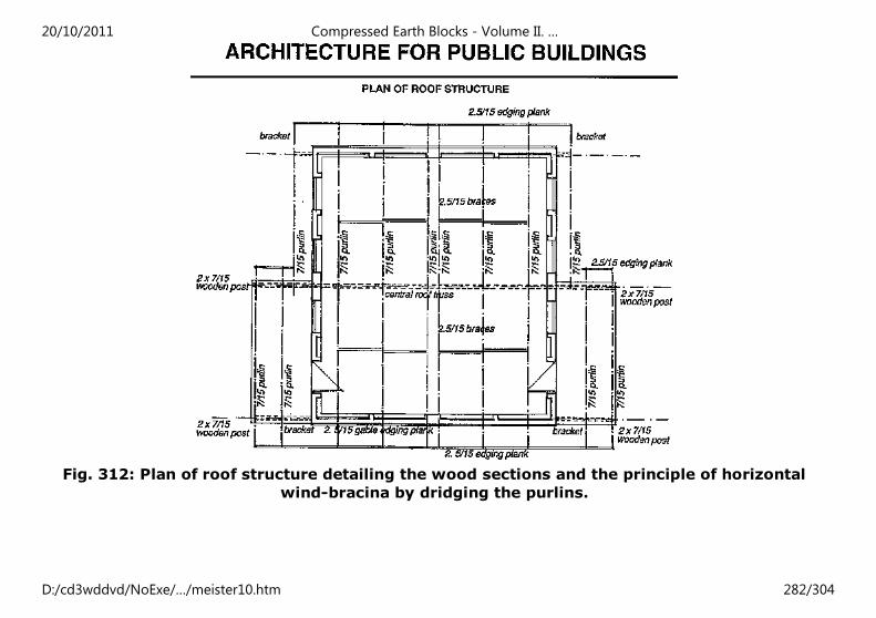
Fig. 312: Plan of roof structure detailing the wood sections and the principle of horizontal
wind-bracina by dridging the purlins.
20/10/2011 Compressed Earth Blocks - Volume II. …
D:/cd3wddvd/NoExe/…/meister10.htm 282/304
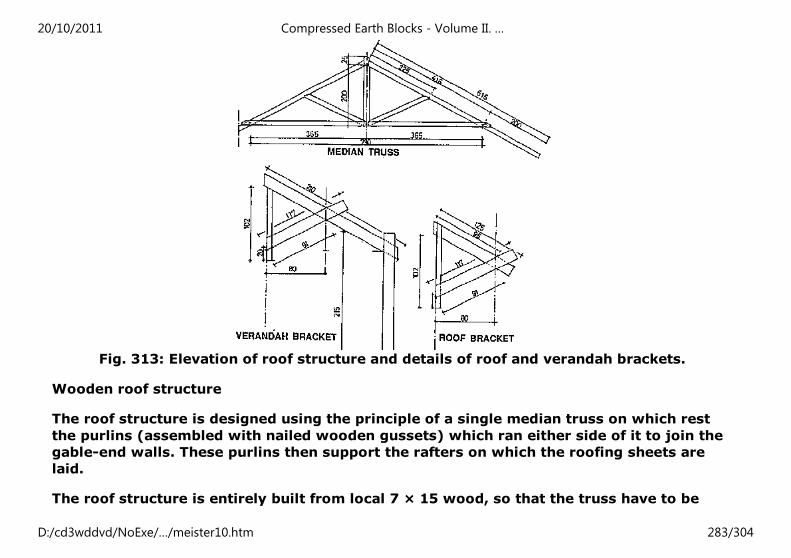
Fig. 313: Elevation of roof structure and details of roof and verandah brackets.
Wooden roof structure
The roof structure is designed using the principle of a single median truss on which rest
the purlins (assembled with nailed wooden gussets) which ran either side of it to join the
gable-end walls. These purlins then support the rafters on which the roofing sheets are
laid.
The roof structure is entirely built from local 7 × 15 wood, so that the truss have to be
20/10/2011 Compressed Earth Blocks - Volume II. …
D:/cd3wddvd/NoExe/…/meister10.htm 283/304
built using tie-beams and trussed rafters bracing the king post and the struts. All the parts
are nailed together.
The truss is laid out, assembled and put together on the ground and then put into position,
temporarily held in place by wooden props. The bracing tie-beam rests on the top of the
masonry pillars intended for this purpose, but with wooden wedges in between. The 7/15
purlins are then laid and made rigid by nailing in the bracing elements on their upper
edge, which hold them in position.
The overhang consoles of the roof along the gutter walls, as well as that of the two
verandahs, are fixed to the bracing tie-beam of the truss by a vertical piece of wood on the
outside of the wall. This vertical piece of wood is also strengthened bye horizontal piece of
wood going through the wall and supporting the slanting part of the bracket. Two 7/15
exterior bracing posts keep the verandah roofs stable.
20/10/2011 Compressed Earth Blocks - Volume II. …
D:/cd3wddvd/NoExe/…/meister10.htm 284/304
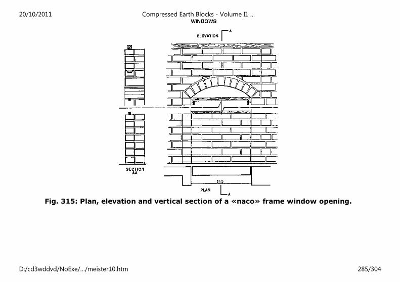
Fig. 315: Plan, elevation and vertical section of a «naco» frame window opening.
20/10/2011 Compressed Earth Blocks - Volume II. …
D:/cd3wddvd/NoExe/…/meister10.htm 285/304
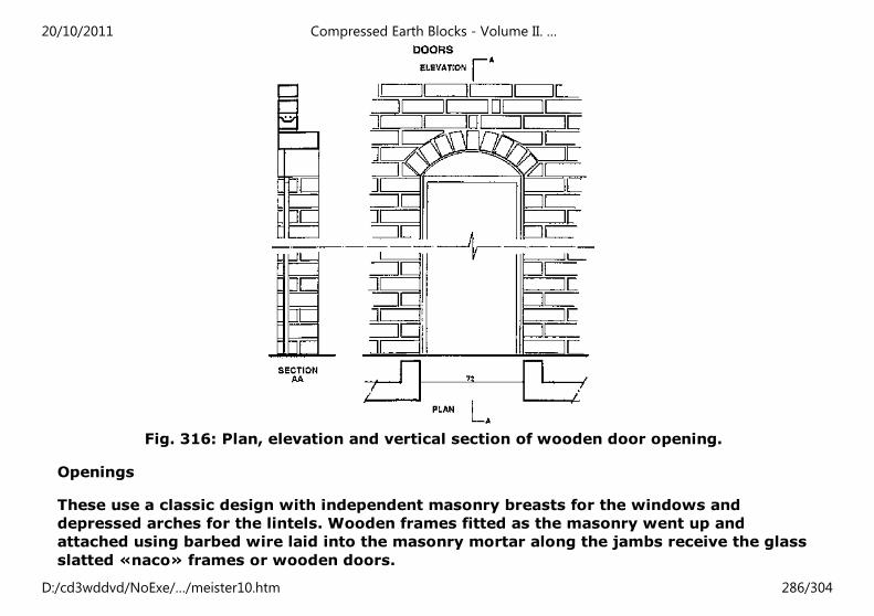
Fig. 316: Plan, elevation and vertical section of wooden door opening.
Openings
These use a classic design with independent masonry breasts for the windows and
depressed arches for the lintels. Wooden frames fitted as the masonry went up and
attached using barbed wire laid into the masonry mortar along the jambs receive the glass
slatted «naco» frames or wooden doors.
20/10/2011 Compressed Earth Blocks - Volume II. …
D:/cd3wddvd/NoExe/…/meister10.htm 286/304
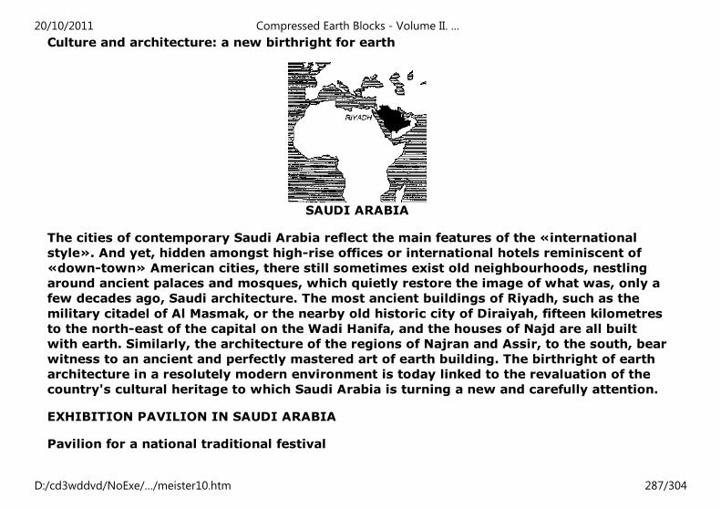
Culture and architecture: a new birthright for earth
SAUDI ARABIA
The cities of contemporary Saudi Arabia reflect the main features of the «international
style». And yet, hidden amongst high-rise offices or international hotels reminiscent of
«down-town» American cities, there still sometimes exist old neighbourhoods, nestling
around ancient palaces and mosques, which quietly restore the image of what was, only a
few decades ago, Saudi architecture. The most ancient buildings of Riyadh, such as the
military citadel of Al Masmak, or the nearby old historic city of Diraiyah, fifteen kilometres
to the north-east of the capital on the Wadi Hanifa, and the houses of Najd are all built
with earth. Similarly, the architecture of the regions of Najran and Assir, to the south, bear
witness to an ancient and perfectly mastered art of earth building. The birthright of earth
architecture in a resolutely modern environment is today linked to the revaluation of the
country's cultural heritage to which Saudi Arabia is turning a new and carefully attention.
EXHIBITION PAVILION IN SAUDI ARABIA
Pavilion for a national traditional festival
20/10/2011 Compressed Earth Blocks - Volume II. …
D:/cd3wddvd/NoExe/…/meister10.htm 287/304
The national traditional festival of Janadriyah (near Riyadh) is generally inaugurated
during the last week of Shaban, just before the start of Ramadan. The event serves to
reaffirm traditional values which are reflected in the festival by the expression of a
multitude of craft activities which have been passed down through generations, such as
cabinet-making, weaving, leatherwork, pottery, wood engraving and painting, dancing,
singing and theatre. A large number of people from nearly every corner of Saudi Arabia
assemble at Janadriyah to celebrate these values and this craftsmanship in a festive
atmosphere. On the occasion of the 1988 festival, the General Secretary of the Royal
Commission of Jubail and Yanbu was invited to set up a permanent exhibition of the
regional products of these two towns. It was decided to adopt the idea of turning once
again to the tradition of building with earth whilst adapting it to the present-day
requirements of workmanship offered by contemporary technologies. The stabilized
compressed earth block met this criterion and a project agreement was reached in
December 1987, in the context of a collaboration between the French Embassy at Riyadh
and the Royal Commission of Jubail and Yanbu.
TECHNICAL FEATURES OF THE PROJECT
An exhibition pavilion, with a covered surface area of 200 m².
Owner: The Royal Commission of the towns of Jubail and Yanbu.
Design: Ibrahim Aba-Alkhail, architect from Riyadh, in collaboration with CRATerre-EAG.
Implementation: CRATerre-EAG with the help of Saudi enterprises and masons.
In collaboration with: the Joseph Fournier University of Grenoble, the King Abdulaziz
University and the King Saud University of Petrols and Minerals (materials analysis).
With the support of the department of international affairs of the Ministry of Culture, of
20/10/2011 Compressed Earth Blocks - Volume II. …
D:/cd3wddvd/NoExe/…/meister10.htm 288/304
Communication and of Major Works; of the French Embassy at Riyadh (cultural service);
and of the Georges Pompidou National Centre for Art and Culture, Paris.
Construction
- Foundations: reinforced concrete ground beams.
- Floor: reinforced concrete.
- Wall masonry: stabilized compressed earth blocks measuring 29.5 × 14 × 9 cm.
Loadbearing walls 29.5 cm thick using a header and double stretcher bonding pattern. 45
cm thick pillars supporting interior arches or reinforced concrete lintel beams over the
interior patio. 14 cm thick roof parapets.
- Roofs: mixed system of terrace roofs, using compressed earth block vaulting and
reinforced concrete girders, and compressed earth block cupolas (at the four corners of
the building) on pendentives. Water-proof render using bitumen and cement mortar over
mesh.
Architectural design
The architectural demands of the project are modest - no more than 200 to 250 m² and
not very complicated. The requirement is for a design for a suitably lit exhibition area.
Ventilation has also to be provided, with «naturally», inspired solutions being preferred to
mechanical machinery. The programme insists on the design of a building in keeping with
the expression of an architectural tradition which can be celebrated in the context of the
Janadriyah festival, by emphasising the use of local materials and traditionally-inspired
decorations, whilst at the same time not merely imitating traditional building forms and
techniques.
20/10/2011 Compressed Earth Blocks - Volume II. …
D:/cd3wddvd/NoExe/…/meister10.htm 289/304
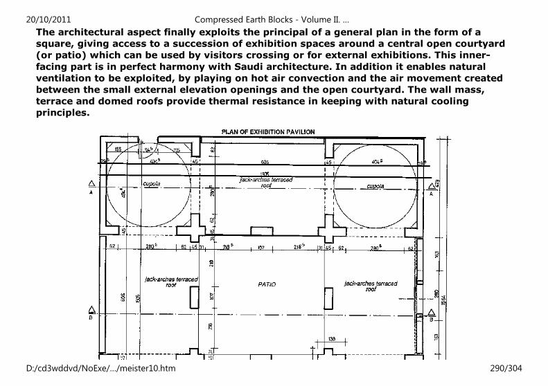
The architectural aspect finally exploits the principal of a general plan in the form of a
square, giving access to a succession of exhibition spaces around a central open courtyard
(or patio) which can be used by visitors crossing or for external exhibitions. This inner-
facing part is in perfect harmony with Saudi architecture. In addition it enables natural
ventilation to be exploited, by playing on hot air convection and the air movement created
between the small external elevation openings and the open courtyard. The wall mass,
terrace and domed roofs provide thermal resistance in keeping with natural cooling
principles.
20/10/2011 Compressed Earth Blocks - Volume II. …
D:/cd3wddvd/NoExe/…/meister10.htm 290/304
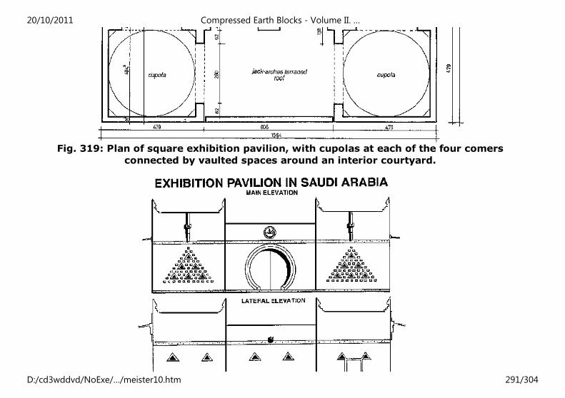
Fig. 319: Plan of square exhibition pavilion, with cupolas at each of the four comers
connected by vaulted spaces around an interior courtyard.
20/10/2011 Compressed Earth Blocks - Volume II. …
D:/cd3wddvd/NoExe/…/meister10.htm 291/304
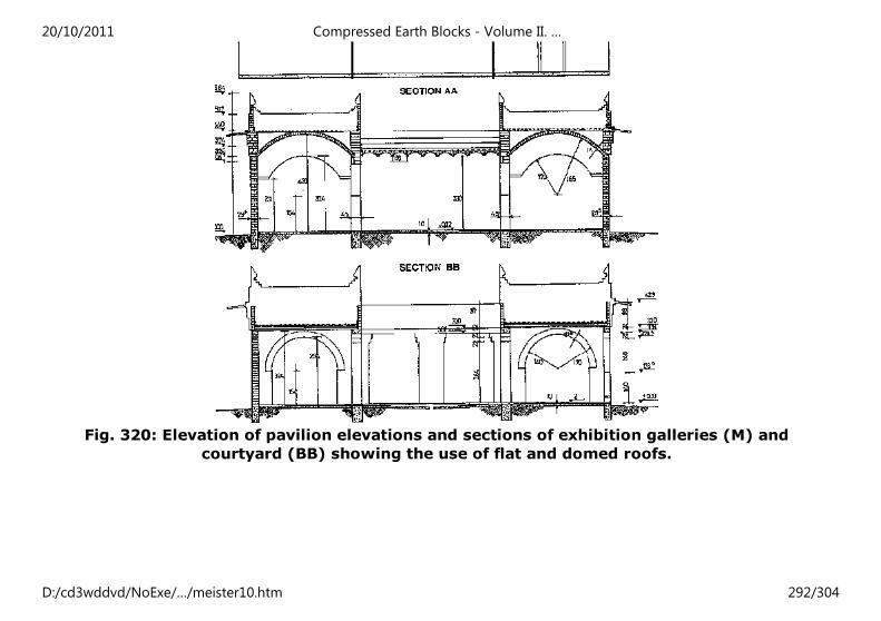
Fig. 320: Elevation of pavilion elevations and sections of exhibition galleries (M) and
courtyard (BB) showing the use of flat and domed roofs.
20/10/2011 Compressed Earth Blocks - Volume II. …
D:/cd3wddvd/NoExe/…/meister10.htm 292/304
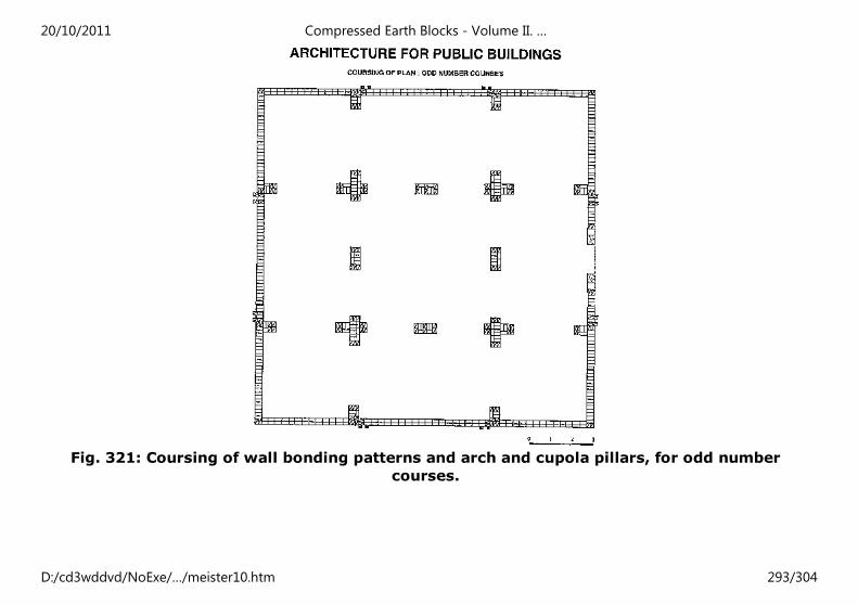
Fig. 321: Coursing of wall bonding patterns and arch and cupola pillars, for odd number
courses.
20/10/2011 Compressed Earth Blocks - Volume II. …
D:/cd3wddvd/NoExe/…/meister10.htm 293/304
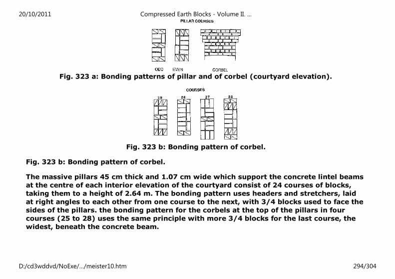
Fig. 323 a: Bonding patterns of pillar and of corbel (courtyard elevation).
Fig. 323 b: Bonding pattern of corbel.
Fig. 323 b: Bonding pattern of corbel.
The massive pillars 45 cm thick and 1.07 cm wide which support the concrete lintel beams
at the centre of each interior elevation of the courtyard consist of 24 courses of blocks,
taking them to a height of 2.64 m. The bonding pattern uses headers and stretchers, laid
at right angles to each other from one course to the next, with 3/4 blocks used to face the
sides of the pillars. the bonding pattern for the corbels at the top of the pillars in four
courses (25 to 28) uses the same principle with more 3/4 blocks for the last course, the
widest, beneath the concrete beam.
20/10/2011 Compressed Earth Blocks - Volume II. …
D:/cd3wddvd/NoExe/…/meister10.htm 294/304
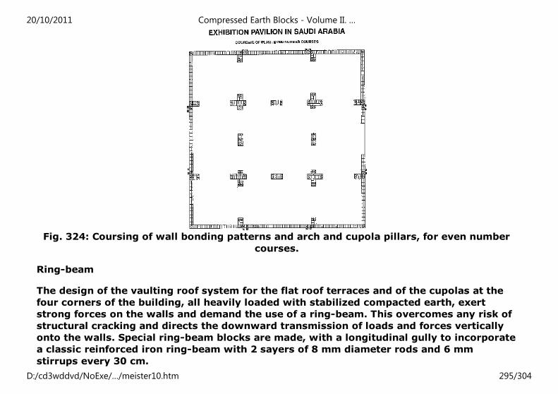
Fig. 324: Coursing of wall bonding patterns and arch and cupola pillars, for even number
courses.
Ring-beam
The design of the vaulting roof system for the flat roof terraces and of the cupolas at the
four corners of the building, all heavily loaded with stabilized compacted earth, exert
strong forces on the walls and demand the use of a ring-beam. This overcomes any risk of
structural cracking and directs the downward transmission of loads and forces vertically
onto the walls. Special ring-beam blocks are made, with a longitudinal gully to incorporate
a classic reinforced iron ring-beam with 2 sayers of 8 mm diameter rods and 6 mm
stirrups every 30 cm.
20/10/2011 Compressed Earth Blocks - Volume II. …
D:/cd3wddvd/NoExe/…/meister10.htm 295/304
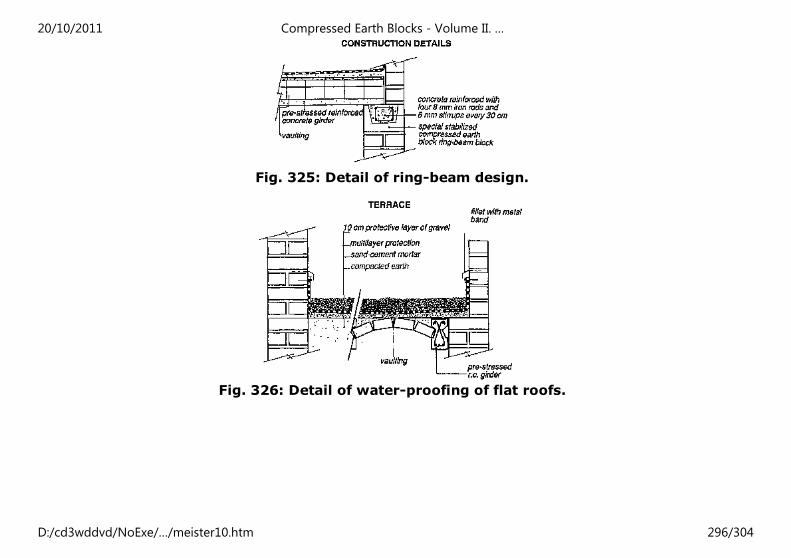
Fig. 325: Detail of ring-beam design.
Fig. 326: Detail of water-proofing of flat roofs.
20/10/2011 Compressed Earth Blocks - Volume II. …
D:/cd3wddvd/NoExe/…/meister10.htm 296/304
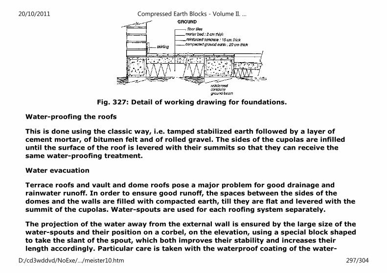
Fig. 327: Detail of working drawing for foundations.
Water-proofing the roofs
This is done using the classic way, i.e. tamped stabilized earth followed by a layer of
cement mortar, of bitumen felt and of rolled gravel. The sides of the cupolas are infilled
until the surface of the roof is levered with their summits so that they can receive the
same water-proofing treatment.
Water evacuation
Terrace roofs and vault and dome roofs pose a major problem for good drainage and
rainwater runoff. In order to ensure good runoff, the spaces between the sides of the
domes and the walls are filled with compacted earth, till they are flat and levered with the
summit of the cupolas. Water-spouts are used for each roofing system separately.
The projection of the water away from the external wall is ensured by the large size of the
water-spouts and their position on a corbel, on the elevation, using a special block shaped
to take the slant of the spout, which both improves their stability and increases their
length accordingly. Particular care is taken with the waterproof coating of the water-
20/10/2011 Compressed Earth Blocks - Volume II. …
D:/cd3wddvd/NoExe/…/meister10.htm 297/304
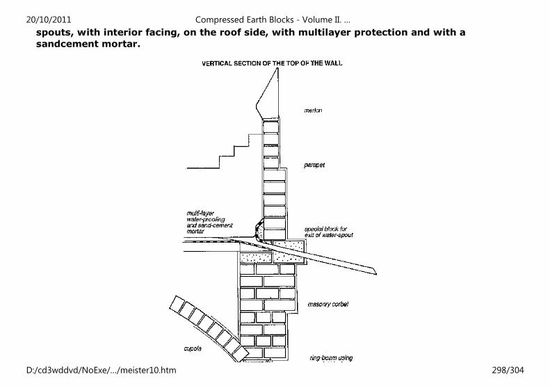
spouts, with interior facing, on the roof side, with multilayer protection and with a
sandcement mortar.
20/10/2011 Compressed Earth Blocks - Volume II. …
D:/cd3wddvd/NoExe/…/meister10.htm 298/304
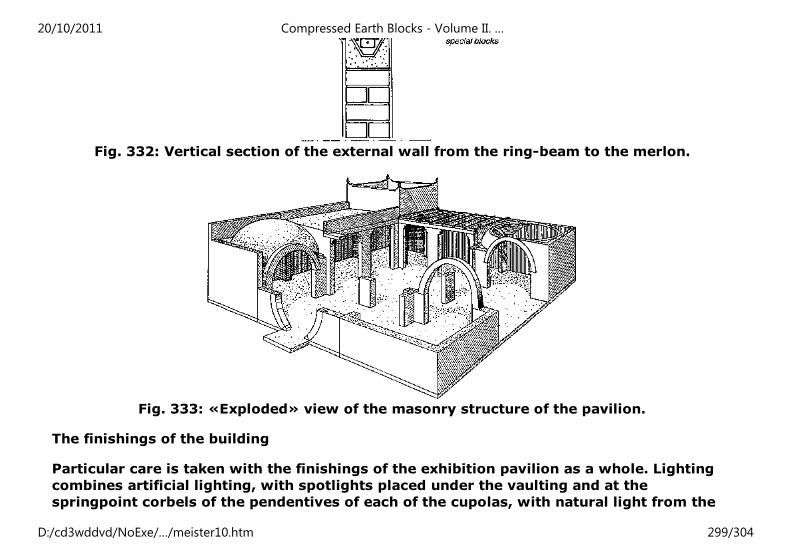
Fig. 332: Vertical section of the external wall from the ring-beam to the merlon.
Fig. 333: «Exploded» view of the masonry structure of the pavilion.
The finishings of the building
Particular care is taken with the finishings of the exhibition pavilion as a whole. Lighting
combines artificial lighting, with spotlights placed under the vaulting and at the
springpoint corbels of the pendentives of each of the cupolas, with natural light from the
20/10/2011 Compressed Earth Blocks - Volume II. …
D:/cd3wddvd/NoExe/…/meister10.htm 299/304
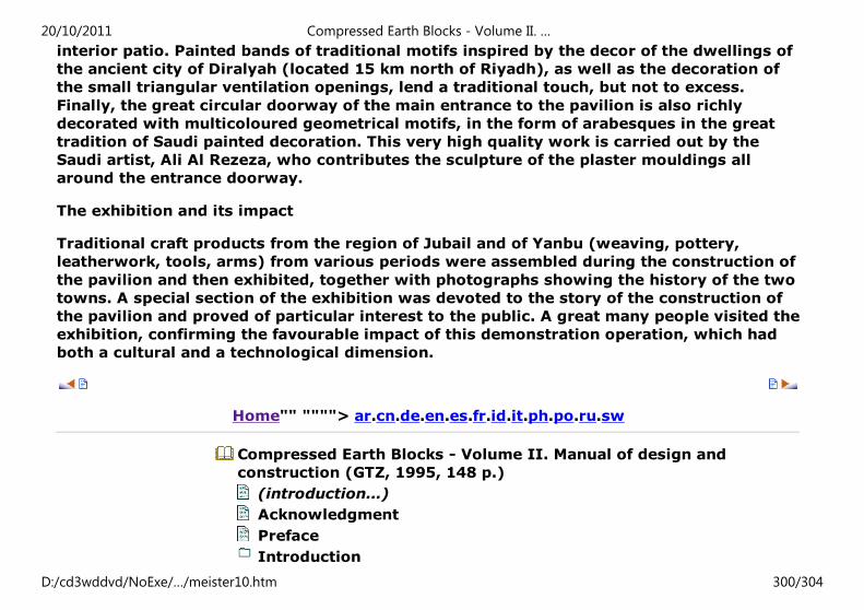
interior patio. Painted bands of traditional motifs inspired by the decor of the dwellings of
the ancient city of Diralyah (located 15 km north of Riyadh), as well as the decoration of
the small triangular ventilation openings, lend a traditional touch, but not to excess.
Finally, the great circular doorway of the main entrance to the pavilion is also richly
decorated with multicoloured geometrical motifs, in the form of arabesques in the great
tradition of Saudi painted decoration. This very high quality work is carried out by the
Saudi artist, Ali Al Rezeza, who contributes the sculpture of the plaster mouldings all
around the entrance doorway.
The exhibition and its impact
Traditional craft products from the region of Jubail and of Yanbu (weaving, pottery,
leatherwork, tools, arms) from various periods were assembled during the construction of
the pavilion and then exhibited, together with photographs showing the history of the two
towns. A special section of the exhibition was devoted to the story of the construction of
the pavilion and proved of particular interest to the public. A great many people visited the
exhibition, confirming the favourable impact of this demonstration operation, which had
both a cultural and a technological dimension.
Home"" """"> ar.cn.de.en.es.fr.id.it.ph.po.ru.sw
Compressed Earth Blocks - Volume II. Manual of design and
construction (GTZ, 1995, 148 p.)
(introduction...)
Acknowledgment
Preface
Introduction
20/10/2011 Compressed Earth Blocks - Volume II. …
D:/cd3wddvd/NoExe/…/meister10.htm 300/304
Masonry principles
The project's building dispositions
Architecture
Bibliografy
Bibliografy
DOCUMENTS ON COMPRESSED EARTH BLOCKS
The Basic of Compressed Earth blocks.CRATerre-EAG, Aus der Arbeit von GATE, Deutsche
Gesellscraft fur Technische Zusammenarbeit (GTZ) GmbH, Eschborn, Germany, 1991.
Compressed earth blocks: production equipment. CRATerre (Houben H.; Rigassi V.; Gamier
Ph.). CRATerre-EAG, Villefontaine, France, CDI-Centre for the Development of Industry,
Brussels, Belgium, 1994.
Compressed Earth Blocks: Manual of Production. CRATerre-EAG, Aus der Arbeit von GATE,
Deutsche Gesellschaft fur Technische Zusammenarbeit (GTZ) GmbH, Eschborn ,Germany,
1983.
Product Information: Soil Blocks Presses, Mukerji K., CRATerre-EAG, Aus der Arbeit von
GATE, Deutsche Gesellschaft far Technische Zusammenarbeit (GTZ) GmbH, Eschborn,
Germany, 1988.
20/10/2011 Compressed Earth Blocks - Volume II. …
D:/cd3wddvd/NoExe/…/meister10.htm 301/304
Product Information: Soil Preparation Equipment, Mukerji K., Worner H., CRATerre-EAG,
Aus der Arbeit von GATE, Deutsche Gesellschaft fur Technische Zusammenarbeit (GTZ)
GmbH, Eschborn, Germany, 1991.
Product Information: Stabilizers and Mortars, CRATerre-EAG, Mukerli K., Aus der Arbeit
von GATE, Deutsche Gesellschaft fur Technische Zusammenarbeit (GTZ) GmbH, Eschborn,
Germany, 1993.
Recommandations pour la conception et l’excution de btiments en gobton. J. Simonet,
LBTP, Abidjan, Ivory Coast, 1979.
Small Scale Manufacture of Stabilized Soil Bricks. Smith R.G.; Webb D.T.J., Technical
Memorandum N° 1 2, International Labour Office, Geneva, Switzerland, 1987.
Stabilized Soil Blocks for Building. Lunt M.G.; Overseas Building Note N°. 184, Building
Research Establishment, Garston, 1980.
The Basics of Compressed Earth Blocks. CRATerre-EAG, Aus der Arbeit von GATE,
Deutsche Gesellschaft fur Technische Zusammenarbeit (GTZ) GmbH, Eschborn, Germany,
1991.
OTHER USEFUL DOCUMENTS
Building with Earth, A Handbook. Norton J., IT Publications, London, United Kingdom,
1986.
Building with Earth. CRATerre-EAG (Doat P.; Hays A.; Houben H.; Matuk S.; Vitoux F.), The
Mud Village Society, New Delhi, India, 1990.
Earth Building Materials and Techniques: Select Bibliography. CRATerre-EAG, Aus der
20/10/2011 Compressed Earth Blocks - Volume II. …
D:/cd3wddvd/NoExe/…/meister10.htm 302/304
Arbeit von GATE, Deutsche Gesellschaft fur Technische Zusammenarbeit (GTZ) GmbH,
Eschborn, Germany, 1991.
Modernit de l’architecture de terre en Afrique. Rsalisations des annes80. CRATerre-EAG
(H.Guillaud), Grenoble, France, 1989.
Recommandations pour la conception des btiments du Quartier en terre de L’Isle d’Abeau.
CRATerre-EAG (d. Belmans, M. Dayre, P. Doat, H. Guillaud, H. Houben) ; groupe pis (G.
Balas, L. Barthoux, J. Bourgin, G. Buet, P. Decousus, D. Esclatine, P. Landry, Ch. Mgard, H.
Pnicaud), AGRA, Plan Construction, Paris, France, 1982.
Building with earth. CRATerre (Doat P., Hays A., Houben H., Matuk S., Vitoux F.,). The Mud
Village Siciety, New Delhi, India, 1990.
An Advisory Service on Earth Building
The Earth Building Advisory Service (EAS) is one part of an advisory and information
service on building materials and construction technologies known as BASIN (Building
Advisory Service and Information Network) which is operated jointly by four European
Institutions (GATE, ITDG, SKAT and CRATerre-EAG).
EAS is provided by CRATerre-EAG (International Centre for Earth Construction - School of
Architecture of Grenoble) which has extensive experience in the production and use of
earthen building materials.
EAS is building up a comprehensive database on documents, technologies, equipment,
institutions and consultants as well as on projects and programmes related to earth
building. This database is used to provide an enquiry service to interested parties world-
wide and to provide the basis for a series of technical guides and publications.
20/10/2011 Compressed Earth Blocks - Volume II. …
D:/cd3wddvd/NoExe/…/meister10.htm 303/304
Within the BASIN framework, CRATerre-EAG runs specific training courses on building
with earth. EAS also undertakes research and development programs in the field of
building materials and their application. This activity includes project monitoring and
evaluation.
For further information, please contact:
CRATerre-EAG
Earth Building Advisory Service (EAS)
Maison Levrat
Parc Fallavier
BP 53
F-38092 Villefontaine Cedex
France
Tel. (33) 74 95 43 91
Fax (33) 74 95 64 21
Telex 308 658 F
20/10/2011 Compressed Earth Blocks - Volume II. …
D:/cd3wddvd/NoExe/…/meister10.htm 304/304


![Author: [Insert Your Username Here]kittysarrayofjewels.weebly.com/.../prompt_5b_going_under_-_co… · Web viewAs a note, ‘fan fiction’ is not preferred, meaning characters](https://img.pdfslide.us/doc/110x75/605e8da48060dd6c404706e2/author-insert-your-username-here-web-view-as-a-note-afan-fictiona-is-not.jpg)