Embed Size (px)
Citation preview
TRI-MAX 20
COMPRESSED AIR FOAM SYSTEM
OPERATIONS, TRAINING, & MAINTENANCE MANUAL
January 1, 2008

2
TABLE OF CONTENTS
CHAPTER 1
INTRODUCTION PAGE Section 1
Manufacturer 3 Section 3
Warranty 3 Section 4
Warnings, Cautions, & Notes 4 Section 5 Manual Changes and Reproduction 4
CHAPTER 2 SYSTEM DESCRIPTION Section 1 General Information 5 Section 2 Specifications 5 Section 3
Transporting 5 Section 4 Components 6
CHAPTER 3 OPERATING INSTRUCTIONS Section 1
Initial Setup 9 Section 2
Foam Products 9 Section 3 System Depressurization 10 Section 4 Preventative Maintenance Checks 10 and Services (PMCS) Section 5 Normal Operating Instructions 13 Section 6 Cold Weather Operations 14 Section 7 Emergency Procedures 14 Section 8 Aviation Refueling Operations 15 Section 9 Fuel Spill Procedures 16
CHAPTER 4 TRAINING Section 1
Training Program 17 Section 2
Training Aid 17 Section 3
Program of Instruction 17
CHAPTER 5 MAINTENANCE Section 1 General Instructions 19 Section 2 Technical Assistance 19

3
Section 3 Repair Parts 19 Section 4 Special Tools & Accessories 21 Section 6 Maintenance Log 22 Section 7 Servicing Under Normal Conditions 24 Section 8 Servicing Under Cold Conditions 27 Section 9 Scheduled Maintenance 28 Section 10 Unscheduled Maintenance 28 Section 11 Troubleshooting 30 Section 12 Storage & Protection 31
CHAPTER 1
INTRODUCTION
1-1. MANUFACTURER: A. The TRI-MAX 20 is manufactured by: Kingsway Sales and Marketing, LLC. 6680 Lockheed Dr. Suite B Redding, CA 96002 Phone: (530) 722-0272 Fax: (530) 722-0450 E-mail: [email protected] Website: www.tri-max.info
B. The manufacturer is totally committed to supporting the owners and operators of the TRI-MAX 20 system. Don’t hesitate to contact the factory either by telephone, E-Mail, FAX, or the Website if you have a problem that you can’t solve or have a product improvement idea. The TRI-MAX website has a Comment/Assistance Page for obtaining product information, providing customer feedback, and soliciting technical assistance.
1-2. WARRANTY: The TRI-MAX 20 is fully warranted for one year from date of
delivery to be free from defects in material and workmanship. The warranty card that accompanies the unit should be returned to the manufacturer. This warranty is limited to parts only. Labor is not included. The manufacturer’s liability is limited solely to the repair or replacement of the defective part. The defective part must be returned to the manufacturer to avoid any charges. The manufacturer shall in no way be liable for any incidental or consequential damages which may result from any defects in material or workmanship or from the breach of any express or implied warranty. The
4
manufacturer does not warranty the performance of the system impacted by environmental conditions and end user competence.
1-4. WARNINGS, CAUTIONS, & NOTES: Are used to emphasize important and
critical instructions and are used for the following conditions:
A. WARNING: An operating procedure, practice, etc., which if not correctly followed could result in personal injury or loss of life.
B. CAUTION: An operating procedure, practice, etc., which, if not strictly
observed, could result in damage to, or destruction of, equipment.
C. NOTE: An operating procedure, condition, etc., which it is essential to highlight.
1-5. MANUAL CHANGES AND REPRODUCTION:
A. MANUAL CHANGES:
(1) The manufacturer will provide equipment update changes to this manual. Each change will be consecutively numbered and have an effective date. The change summary sheet should be filed in the front section of the manual prior to the Table of Contents.
(2) This manual and the associated updates will be posted on the TRI-
MAX web site.
(3) Users can help improve this manual by providing any errors, inconsistencies, helpful information, or recommended improvements to the manufacturer. All recommendations submitted should reference the appropriate Chapter/Paragraph (if applicable) and the name and contact (phone, e-mail, fax, etc) for the person submitting the information.
B. REPRODUCTION: Reproduction of all information, illustrations, and checklists in this manual is authorized.

5

6
CHAPTER 2
SYSTEM DESCRIPTION 2-1. GENERAL INFORMATION: The TRI-MAX 20 Compressed Air Foam fire
suppression system uses compressed air to propel fire fighting foam. Thousands of tight radius bubbles quickly cool and smother a fire by providing a thick vapor-sealing blanket of foam that virtually eliminates re-ignition. The foam will adhere to horizontal and vertical surfaces. This system allows the operator to seal a fuel spill and flammable vapors with foam thus reducing or eliminating a potential fire. The 20 gallon system produces approximately 400 gallons of finished foam. It takes approximately 1.5 minutes, in the full open position, to fully discharge the 400 gallons of finished foam. The system will discharge the foam approximately 75-85 feet in a no wind condition allowing fire fighting personnel without protective clothing to avoid thermal injuries. There is an approximate 25% reduction in discharge distance using the Freeze Protected Foam solutions at -40 degrees F/C due to the increased viscosity of the foam. The system can easily be serviced by the operator. Trained personnel can accomplish all maintenance except the hydrostatic pressure testing of the Air Cylinders, Premix Tank, and the Discharge Hose, which is required every five (5) years.
2-2. SPECIFICATIONS:
A. Height: 48 ¾ inches Width: 20 inches Depth: 25 ¼ inches B. Loaded Weight: 400 LBS Empty Weight: 240 LBS C. Premix Tank: 20-gallon capacity D. Finished Foam Capacity: Approximately 400 gallons E. Discharge Nozzle: 1” standard or pistol grip style F. Discharge Rate (max): 300 gal/minute of finished foam G. Foam Discharge Distance: 75-85 feet in a no wind condition
(50-60 feet at –40 degrees F/C using Freeze Protected Foam solution) H. Air Cylinder (Scuba): Two (2) 50 CF 3000 psi I. Regulator: Aqua Environment 415A adjustable pressure 0-400 psi J. Dispensing Hose: 50 feet of 1” collapsible hose K. Hose Length (max): 200 feet L. Pressure Relief Valve: 200 psi M. Air Hose: ¼ inch 3000 psi N. Ball Valves: 400 psi O. Check Valves: Two one-way P. Recharge Time: 6-8 minutes
2-3. TRANSPORTING: The TRI-MAX 20 should be thoroughly secured when transporting in trailers and vehicles. Utilize the frame when re-positioning the system. Do not push on any of the components (i.e. gauges, regulators etc.) when moving the system.
7
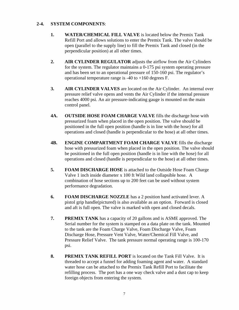
2-4. SYSTEM COMPONENTS:
1. WATER/CHEMICAL FILL VALVE is located below the Premix Tank Refill Port and allows solutions to enter the Premix Tank. The valve should be open (parallel to the supply line) to fill the Premix Tank and closed (in the perpendicular position) at all other times.
2. AIR CYLINDER REGULATOR adjusts the airflow from the Air Cylinders
for the system. The regulator maintains a 0-175 psi system operating pressure and has been set to an operational pressure of 150-160 psi. The regulator’s operational temperature range is -40 to +160 degrees F.
3. AIR CYLINDER VALVES are located on the Air Cylinder. An internal over
pressure relief valve opens and vents the Air Cylinder if the internal pressure reaches 4000 psi. An air pressure-indicating gauge is mounted on the main control panel.
4A. OUTSIDE HOSE FOAM CHARGE VALVE fills the discharge hose with
pressurized foam when placed in the open position. The valve should be positioned in the full open position (handle is in line with the hose) for all operations and closed (handle is perpendicular to the hose) at all other times.
4B. ENGINE COMPARTMENT FOAM CHARGE VALVE fills the discharge
hose with pressurized foam when placed in the open position. The valve should be positioned in the full open position (handle is in line with the hose) for all operations and closed (handle is perpendicular to the hose) at all other times.
5. FOAM DISCHARGE HOSE is attached to the Outside Hose Foam Charge
Valve 1 inch inside diameter x 100 ft Wild land collapsible hose. A combination of hose sections up to 200 feet can be used without system performance degradation.
6. FOAM DISCHARGE NOZZLE has a 2 position hand activated lever. A
pistol grip handle(pictured) is also available as an option. Forward is closed and aft is full open. The valve is marked with open and closed decals.
7. PREMIX TANK has a capacity of 20 gallons and is ASME approved. The
Serial number for the system is stamped on a data plate on the tank. Mounted to the tank are the Foam Charge Valve, Foam Discharge Valve, Foam Discharge Hose, Pressure Vent Valve, Water/Chemical Fill Valve, and Pressure Relief Valve. The tank pressure normal operating range is 100-170 psi.
8. PREMIX TANK REFILL PORT is located on the Tank Fill Valve. It is
threaded to accept a funnel for adding foaming agent and water. A standard water hose can be attached to the Premix Tank Refill Port to facilitate the refilling process. The port has a one way check valve and a dust cap to keep foreign objects from entering the system.
8
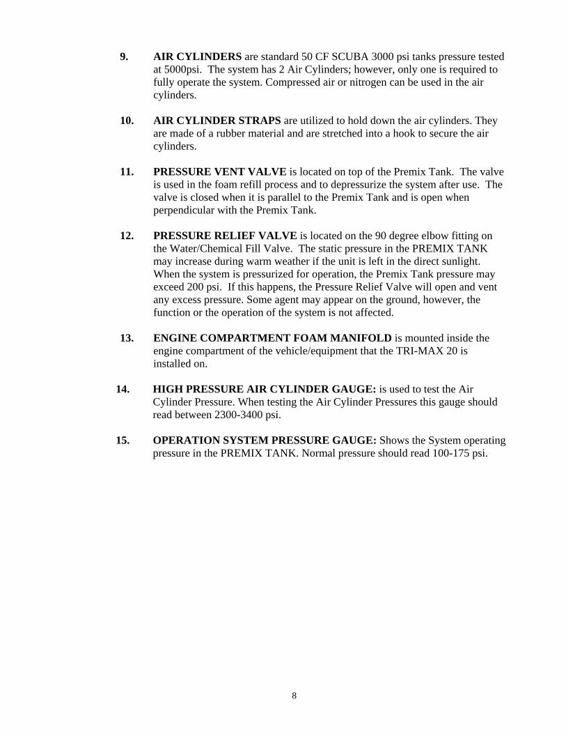
9. AIR CYLINDERS are standard 50 CF SCUBA 3000 psi tanks pressure tested at 5000psi. The system has 2 Air Cylinders; however, only one is required to fully operate the system. Compressed air or nitrogen can be used in the air cylinders.
10. AIR CYLINDER STRAPS are utilized to hold down the air cylinders. They
are made of a rubber material and are stretched into a hook to secure the air cylinders.
11. PRESSURE VENT VALVE is located on top of the Premix Tank. The valve
is used in the foam refill process and to depressurize the system after use. The valve is closed when it is parallel to the Premix Tank and is open when perpendicular with the Premix Tank.
12. PRESSURE RELIEF VALVE is located on the 90 degree elbow fitting on
the Water/Chemical Fill Valve. The static pressure in the PREMIX TANK may increase during warm weather if the unit is left in the direct sunlight. When the system is pressurized for operation, the Premix Tank pressure may exceed 200 psi. If this happens, the Pressure Relief Valve will open and vent any excess pressure. Some agent may appear on the ground, however, the function or the operation of the system is not affected.
13. ENGINE COMPARTMENT FOAM MANIFOLD is mounted inside the
engine compartment of the vehicle/equipment that the TRI-MAX 20 is installed on.
14. HIGH PRESSURE AIR CYLINDER GAUGE: is used to test the Air
Cylinder Pressure. When testing the Air Cylinder Pressures this gauge should read between 2300-3400 psi.
15. OPERATION SYSTEM PRESSURE GAUGE: Shows the System operating
pressure in the PREMIX TANK. Normal pressure should read 100-175 psi.

9
TRI-MAX 20 COMPONENTS
10
CHAPTER 3
OPERATING INSTRUCTIONS 3-1. INITIAL SETUP: The TRI-MAX 20 comes fully assembled and the Air Cylinders
are charged unless the unit is shipped by air. Users should turn on the Air Cylinder handles and verify there is 2300-3400 psi pressure. The Air Cylinders should be refilled if the cylinder pressure is less than 2300 psi. The 20 gallon Premix Tank must be filled prior to use. The proper Aqueous Film Forming Foam (AFFF) solution should be selected based on operational ambient temperatures prior to putting the unit in service. Liquid dish soap can be used in the Premix Tank if training is going to be conducted. The dish soap does not harm the system and can be mixed with the AFFF without any performance degradation.
3-2 FOAM SOLUTION PRODUCTS:
A. The TRI-MAX 20 can use any type of AFFF fire suppression foam chemical solution. Recommended foam chemicals include Class A foam, Class B foam, Fire-Trol or Terra Foam, and Freeze Protected AFFF Foam (in sub zero temperature environments). Terra Foam provides 24 hour extended structure protection. Class B MC-1 Hazmat approved foam contains enzyme emulsifier that breaks down petroleum products and makes them potable. All recommended foams are EPA, USDA, and OSHA approved.
B. The following amounts of foam solution should be added to the 20 gallon
Premix Tank:
(1) Class A (Wild land) foam : 1.3 quarts (2) Class B 3% solution: 2/3 gallon (3) Class B 6% solution: 1.5 gallons (4) Liquid Dish soap or Training Foam solution (Training only): 3 quarts (5) Freeze Protected Foam solution: 30 gallons (6) Other foam products: Follow the foam manufacturer’s
recommendation.
C. It is recommended that freeze protected foam solution be used in the concentrate form when positioning the units outside during freezing weather Freeze protected solutions should be used at full strength and not mixed with water.
11
3-3. SYSTEM DEPRESSURIZATION
CAUTION
Ensure the Premix Tank is depressurized and the Air Cylinders are closed before conducting any maintenance on the system.
A. Close the Air Cylinder Valves.
B. Close the Foam Charge Valve (if open).
C. Open the Pressure Vent Valve slowly to relieve the Premix Tank and gauge
pressures. D. Close the Pressure Vent Valve after the system has been depressurized. 3-4. PREVENTATIVE MAINTENANCE CHECKS & SERVICES (PMCS) A. Recommend the PMCS CHECKLIST be completed every month. B. Personnel completing the PMCS should be thoroughly familiar with the TRI-MAX 20 system and the information in this manual.
C. Recommend a tag be maintained on each unit that indicates the date and the initials of the individual completing the PMCS, the type and ratio of the AFFF in the Premix Tank, and the location of the MSDS for an emergency situation.
12
TRI-MAX 20 PREVENTATIVE MAINTENANCE CHECKS AND SERVICES
(PMCS) CHECKLIST
DATE COMPLETED____________________
NAME ________________________ SIGNATURE_____________________________ _____ 1. Conduct a visual inspection of the system for chaffing lines, loose lines, dirt,
corrosion or damage. Check that the O-ring is not protruding where the Air Cylinder valve screws into the Air Cylinder. If the O-ring is protruding, the cylinder should be removed and the O-ring replaced.
_____ 2.
A. Turn on one air cylinder and note pressure. Close the air cylinder and check the pressure on the remaining air cylinder.
(1) Conduct a leak check if either Air Cylinder pressure is below
2300 psi: (a) Turn on Air Cylinder(s) with broken seal. (b) Spray a light soap solution on all air lines and fittings.
(c) Tighten fittings, replace O-rings, or replace leaking component.
(2) Remove, recharge, and reinstall Air Cylinders
(Continued on following page)

13
TRI-MAX 20 PMCS CHECKLIST (Continued)
B. Check the Premix Tank level, Air Cylinder Valve and the Foam Charge Valve.
(1) Open the Water/Chemical and Pressure Vent Valves.
(2) Slowly tip the unit towards the 45 degree position. Note that solution flows from the overflow tube.
(3) Fill up the Premix Tank if low. (4) Close the Water/Chemical Valves.
_____ 3. Note any other problems: _______________________________________________________________________ _______________________________________________________________________ _______________________________________________________________________ _______________________________________________________________________ _______________________________________________________________________ _______________________________________________________________________ _______________________________________________________________________ _______________________________________________________________________ _______________________________________________________________________ _______________________________________________________________________ _______________________________________________________________________ _______________________________________________________________________ _______________________________________________________________________

14
3-5. NORMAL OPERATING INSTRUCTIONS
WARNING
The TRI-MAX 20 discharges foam solution at a high pressure. A sudden pressure surge could cause the operator to lose control of the hose if the nozzle and hose are not held securely when the Foam Discharge Nozzle is opened. Open the nozzle slowly to the
full open position.
Consult the foam manufacturer’s MSDS for the proper precautions and treatments if the foam is sprayed into the facial area (eyes, nose, and mouth).
NOTE
It is recommended that the air cylinders normally be left in the closed position.
A. Ensure the Foam Discharge Nozzle is in the closed (forward) position.
B. Open one Air Cylinder by turning the valve counter clockwise.
C. Extend the hose.
D. Turn on the Foam Charge Valve slowly to the full open position (handle should be in line with the hose).
E. Aim the Nozzle at the base of the fire and open the Foam Discharge Valve
slowly (rear position).
F. Shoot the system in 5 to 10 second bursts across the base of the fire or directly on objects that are on fire. Move the nozzle slowly to build up a layer of foam over the fire surface.
15
3-6. COLD WEATHER OPERATIONS
A. It is recommended that the TRI-MAX 20 system be equipped with the Arctic Regulator, Arctic Discharge Hose, Protective Cover and the freeze protected foam solutions when extreme cold weather conditions are anticipated.
B. There will be a degraded performance in extreme cold weather since the
viscosity and density of the foam is greater. C. The foam blanket in cold temperatures will be wetter and the discharge
distances will decrease. Users should anticipate a discharge distance of 50-60 feet in sustained Sub 0 temperatures.
D. The foam will tend to skip a short distance on a frozen surface so the person
employing the system should aim short of the intended target. 3-7. EMERGENCY PROCEDURES
A. LOOSE HOSE WARNING
Do not attempt to catch a runaway hose.
(1) Move to the unit and close the Foam Charge Valve immediately (valve
handle should be perpendicular to the hose).
(2) Close the Foam Discharge Nozzle (valve handle is full forward).
IF CONTINUING TO FIGHT THE FIRE:
(3) Open Foam Charge Valve slowly.
(4) Hold the hose securely and open the Foam Discharge Nozzle slowly (valve handle should be full aft).
B. NO FOAM DISCHARGE
(1) Close the Foam Discharge Nozzle (move the handle full forward).
(2) Close the Foam Charge Valve. (3) Open the backup Air Cylinder Valve.
(4) Open Foam Charge Valve slowly (valve handle should be in line with the hose).
(5) Hold the hose securely and open the Foam Discharge Nozzle (valve
handle is full aft) slowly.
16
C. SHUT DOWN PROCEDURES
(1) Close the Foam Discharge Nozzle. (2) Close the Foam Charge Valve.
(3) Close the Air Cylinder Valve.
(4) Open the Foam Discharge Nozzle to depressurize the hose. Close the valve when all of the foam has been expended from the hose.
(5) Open the Pressure Vent Valve slowly until all pressure is relieved. (6) Secure the fire hose. 3-8 AVIATION REFUELING OPERATIONS
A. Helicopter hot refuel operations are by nature hazardous. An accident during refueling can result in catastrophic damage to the aircraft and possible injury or loss of life to the refuel/aircraft crew. The TRI-MAX 20 provides the user a stand off capability along with the ability to prevent fires by covering up flammable liquids, sealing vapors, and cooling the surface.
B. The following techniques will help prevent catastrophic affects of accidents
and reduce the overall risk of aviation refueling operations:
(1) FIREGUARDS: The protective cover (if utilized) should be removed from the unit and the hose be moved to the fireguard position. Fireguards should stand just outside the rotor disc at a 45 degree angle on the side of the aircraft the refueling nozzle is located on. This position allows the fire guard the best view to monitor the refuel operation, alert the crew to any problem, and quickly react to a fire or fuel spill situation while remaining well clear of the affected area. Priorities should be given to the crew, the fuel spill, and the main fire areas.
(2) IN THE EVENT A FIRE OCCURS: The safety of the re-fueler and
aircraft crew is the number one priority. Fuel burning in the vicinity of the aircrew should be extinguished first. Open the Foam Discharge Nozzle fully and sweep the foam stream across the base of the flames starting at the leading edge and moving slowly to the rear. Use short 5-10 second bursts checking the effectiveness of the foam between bursts. Once the fuel on the ground has been extinguished, begin foaming any remaining portion of the aircraft that is burning.
17
AVIATION REFUELING OPERATIONS (continued next page)
(3) IF FUEL HAS BEEN SPILLED ON THE GROUND AND THE
AIRCRAFT: Foam the aircraft first by positioning the Foam Discharge Nozzle to the full open position in order to get the maximum foam possible on the aircraft. Fuel spilled in the vicinity of the engine, exhaust, or the intake should be foamed immediately to prevent ignition. Once the aircraft has been foamed, the fuel on the ground should be covered with a blanket of foam. Monitor the crew egress and reapply foam to any areas where the foam blanket has been compromised. This action can be accomplished in approximately 20 seconds by a trained fireguard. Quick action on the part of the fireguard is critical to prevent a fuel spill from becoming a fuel fire.
3-9. FUEL SPILL PROCEDURES:
A. The hazard of fuel spills can be reduced by applying a blanket of foam on top of the fuel to seal vapors and reduce the chance of combustion.
B. Cover any personnel who have been drenched with fuel with foam to prevent
combustion.
WARNING
Do not hit the spilled fuel directly with an unrestricted flow of foam or with the Nozzle in the full open position. This action could spread the fuel creating a greater hazard and cause injury to refuel personnel. The operator should be positioned a minimum of 30-40 feet from the fire to maximize the effectiveness of the system. Personnel exposed to foam should follow the instructions listed in the foam manufacturer’s Material Safety Data Sheet (MSDS).

18
CHAPTER 4
TRAINING
4-1. TRAINING PROGRAM
A. Training on the TRI-MAX 20 system should be conducted at least annually for all operators.
B. Maintainers should complete initial training and refresher training as required.
C. Trainers should be thoroughly familiar with the system, fire behavior, hazard
identification and basic fire fighting skills.
D. Operator training should be conducted using a “hands-on” approach in a live fire scenario whenever possible. Live fire training can often be accomplished through coordination with a local fire department.
4-2. TRAINING AIDS: Liquid dish soap or training foam can be mixed with water at a
ratio of 1 gallon per 30 gallon tank providing the training is being conducted in non-freezing environment. The training solution should be placed in the Premix Tank when it is almost full of water in order to maximize the volume of solution available. Dish soap does not cause any damage to the system and can be mixed with AFFF without any impact on the operation.
4-3. TRAINING PROGRAM OF INSTRUCTION (POI):
A. OPERATORS & MAINTAINERS
(1) Component Identification (Pages 6-7)
(2) PMCS (Pages 9-11)
(3) Normal and Cold Weather Operating Instructions (Pages 12-13)
(4) Emergency Procedures (Pages 13-14)
(5) Aviation Refueling Operations (if applicable) (Page 15)
(6) Fuel Spill Operations (Page 15)
(7) Hands-On Operation, preferably on a live fire scenario (Page 12)

19
B. MAINTAINERS
(1) General Maintenance Instructions and Technical Assistance (Page 19) (2) Repair Parts and Special Tools (Pages 19-21) (3) Foam Solution Products (Page 8) (4) Maintenance Log (Pages 24-25)
(5) Servicing Under Normal and Cold Conditions (Pages 26-29)
(6) Scheduled Maintenance (Page 30)
(7) Unscheduled Maintenance (Pages 30-32) (10) Troubleshooting Procedures (Page 33) (11) Storage and Protection (Page 34)
20
CHAPTER 5
MAINTENANCE 5-1. GENERAL INSTRUCTIONS
A. The TRI-MAX 20 system was designed to be easy to operate and simple to maintain. The system has few moving parts; however, it is a vital lifesaving piece of equipment that requires some minimal maintenance.
B. It is recommended that the monthly PMCS be accomplished.
C. It is also very important that responsible personnel be assigned the
responsibility to service and maintain the system.
D. The final important task is maintaining thorough documented records of the maintenance performed. These records should include copies of the completed PMCS Checklists, the Maintenance Log, when the Premix Tank was filled and the type/mixture of foam in each unit. A MSDS sheet should be readily available for the type of foam being utilized. Recommend a tag be affixed to each unit that lists the date and initials of the individual performing the PMCS, the foam type and mixture ratio (if any), and the location of the MSDS.
5-2. TECHNICAL ASSISTANCE: The manufacturer is totally committed to providing
technical assistance whenever required. Maintainers should contact the manufacturer whenever a problem arises that cannot be solved using the information in this manual or when unusual situations are encountered.
5-3. REPAIR PARTS
A. The TRI-MAX 20 repair parts are listed in this paragraph. All repair parts can be obtained from the manufacturer by using a credit card or a purchase order. Many of the parts can also be purchased at local dive shops or hardware stores. O-rings should be purchased from the factory, an authorized TRI-MAX distributor, or from a certified scuba shop.
B. The manufacturer will replace parts that fail due to defects in workmanship
during the one-year warranty period at no cost. The defective part must be returned to the manufacturer to receive credit. Users should contact the manufacturer by phone, e-mail, fax, or by completing the comment page on the website to receive replacement parts.

21
TRI-MAX 20 REPAIR PARTS
NOMENCLATURE
PART NO.
ADAPTER, Funnel Garden Hose 52 ADAPTER, Tank Fill Garden Hose 18 ADAPTER, CGA x Scuba Bottle Recharges 450 AIRLINE, 1/4 Inch x 12 Inch 8A AIRLINE, 1/4 Inch x 13 Inch 8 AIRLINE, 1/4 Inch x 14 Inch 8B CAP, Nozzle Screw-On 78 CAP, Tank Fill Dust 71 CHECKVALVE, Flapper Gravity (3/4 Inch) 16 CHECKVALVE, Pressure (1/2 Inch) 12 COVER, Protective TM30C CYLINDER, Air 35 DECAL, Operation Instructions Pictorial 44-6 DECAL, Air Cylinder Not For Scuba Ops 44-14 GAUGE, Premix Tank (3 Inch) 34L GAUGE, Air Cylinder (3 Inch) 34H FRAME 75 FUNNEL, 2 Qt. 41 HANDLE, Foam Charge Valve 100 HOSE, Arctic Discharge (1 Inch x 50 Ft.) 28A HOSE, Standard Discharge (1 Inch x 50 Ft.) 28B HOSE, Wildfire Discharge (1 Inch x 50 Ft.) 28F KEY, Air Cylinder Retaining Plate Lock 81 LOCK, Air Cylinder Retaining Plate 80 MANUAL, TRI-MAX 20 101-20ARD NOZZLE, Adjustable Fan 426 NOZZLE, Standard Foam Discharge 29 NOZZLE, Pistol Grip Discharge 29P
22
TRI-MAX 20 REPAIR PARTS
(Continued)
NOMENCLATURE
PART NO.
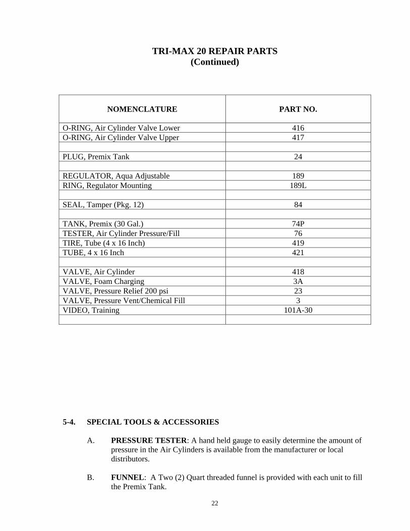
O-RING, Air Cylinder Valve Lower 416 O-RING, Air Cylinder Valve Upper 417 PLUG, Premix Tank 24 REGULATOR, Aqua Adjustable 189 RING, Regulator Mounting 189L SEAL, Tamper (Pkg. 12) 84 TANK, Premix (30 Gal.) 74P TESTER, Air Cylinder Pressure/Fill 76 TIRE, Tube (4 x 16 Inch) 419 TUBE, 4 x 16 Inch 421 VALVE, Air Cylinder 418 VALVE, Foam Charging 3A VALVE, Pressure Relief 200 psi 23 VALVE, Pressure Vent/Chemical Fill 3 VIDEO, Training 101A-30 5-4. SPECIAL TOOLS & ACCESSORIES
A. PRESSURE TESTER: A hand held gauge to easily determine the amount of pressure in the Air Cylinders is available from the manufacturer or local distributors.
B. FUNNEL: A Two (2) Quart threaded funnel is provided with each unit to fill
the Premix Tank.

23
5-5 Maintenance Log
TRI-MAX 20 MAINTENANCE LOG
PREVENTATIVE MAINTENANCE CHECKS & SERVICES (PMCS)
SCHEDULED DATE DATE COMPLETED SIGNATURE SCHEDULED MAINTENANCE DATE DATE ACTION DUE COMPLETED SIGNATURE Check Air Cylinder __________ ___________ _________________ pressures (6 months) Wash unit & apply __________ ___________ _________________ WD40 or equivalent (6 months) over non-painted surfaces Lubricate and recycle __________ ___________ _________________ pressure relief valve (6 months) Lubricate wheel bearings __________ ___________ _________________ (6 months) Air Cylinder __________ ___________ _________________ visual inspection (12 months) and certification
__________________________________________________________________________________________________________________________________________________________
__________________________________________________________________________________________________________________________________________________________
_______________________________________________________________________________________________________________________________________________________________________________________________________________________________________
24
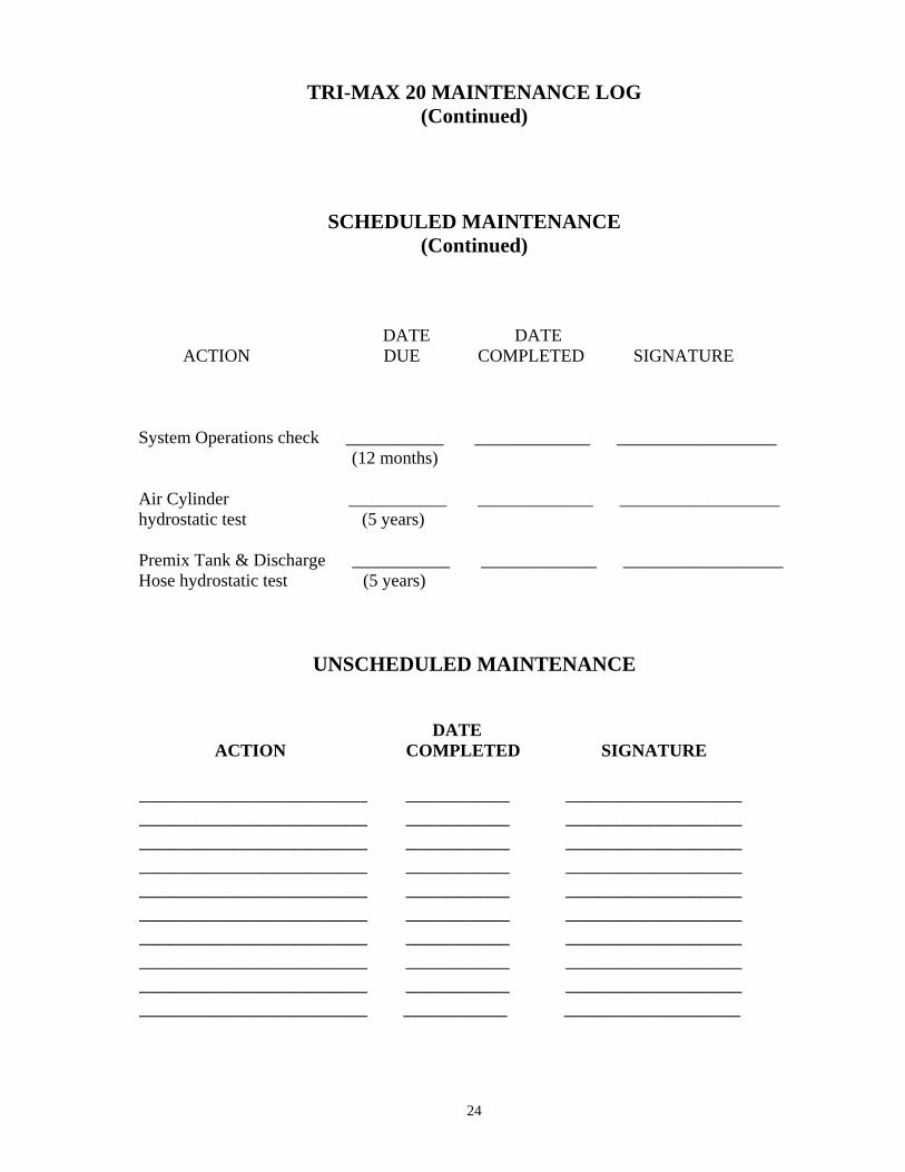
TRI-MAX 20 MAINTENANCE LOG (Continued)
SCHEDULED MAINTENANCE (Continued)
DATE DATE ACTION DUE COMPLETED SIGNATURE System Operations check ___________ _____________ __________________ (12 months) Air Cylinder ___________ _____________ __________________ hydrostatic test (5 years) Premix Tank & Discharge ___________ _____________ __________________ Hose hydrostatic test (5 years)
UNSCHEDULED MAINTENANCE
DATE ACTION COMPLETED SIGNATURE ______________________ __________ _________________ ______________________ __________ _________________ ______________________ __________ _________________ ______________________ __________ _________________ ______________________ __________ _________________ ______________________ __________ _________________ ______________________ __________ _________________ ______________________ __________ _________________ ______________________ __________ _________________ ______________________ __________ _________________

25
5-6. SERVICING UNDER NORMAL CONDITIONS
A. SYSTEM PRESSURE CHECK
(1) Ensure the Pressure Vent Valve, Water/Chemical Fill Valve, and the Foam Charge Valves are closed.
(2) Open one Air Cylinder and check the pressure reading on the gauge is
between 2300-3400 psi. Check the pressure on the Premix Tank gauge, if installed, is between 150-160 psi. Close the Air Cylinder and open the Pressure Vent Valve to release pressure in the Premix Tank. Open the other Air Cylinder and check for an operating pressure of 2300-3400 psi. Close the Air Cylinder.
(3). Conduct a leak check if either Air Cylinder pressure is below 2300 psi
or if any air noise or solution leaks are detected.
(a) Spray a light soap solution on all air lines and fittings to check for leaks.
(b) Tighten leaking fittings or replace O-rings.
(c) Contact manufacturer if regulator has an internal leak. (d) Recharge and replace the Air Cylinder(s).
B. AIR CYLINDER PRESSURE CHECK, RECHARGE AND REPLACEMENT
CAUTION
Ensure the system is depressurized before conducting any maintenance on the system. The Air Regulator can be damaged if removal is attempted with pressure in the system. Extreme care should be used when handling and transporting the Air Cylinders. Do not fully drain the Air Cylinders as this will allow moisture to enter the cylinders. Ensure that all replacement o-rings for the Air Cylinder valve and the Air Cylinders are purchased from the factory, a TRI-MAX distributor, or a certified scuba shop
NOTE Ensure the O-ring is secured when removing and transporting the Air Cylinder.
26
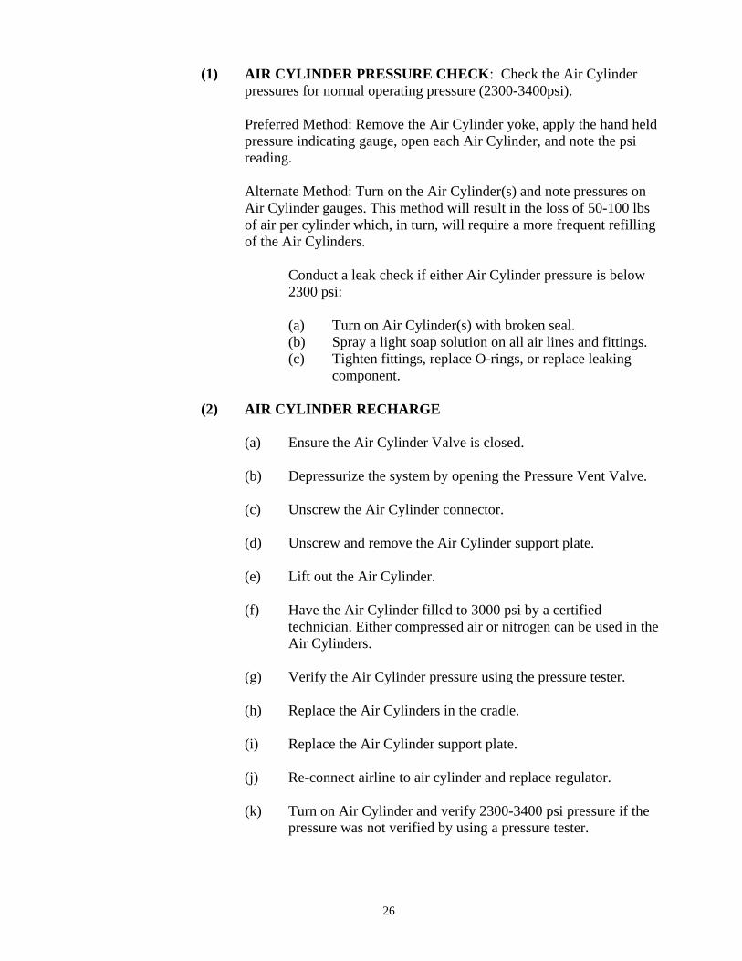
(1) AIR CYLINDER PRESSURE CHECK: Check the Air Cylinder pressures for normal operating pressure (2300-3400psi).
Preferred Method: Remove the Air Cylinder yoke, apply the hand held pressure indicating gauge, open each Air Cylinder, and note the psi reading.
Alternate Method: Turn on the Air Cylinder(s) and note pressures on Air Cylinder gauges. This method will result in the loss of 50-100 lbs of air per cylinder which, in turn, will require a more frequent refilling of the Air Cylinders.
Conduct a leak check if either Air Cylinder pressure is below 2300 psi:
(a) Turn on Air Cylinder(s) with broken seal. (b) Spray a light soap solution on all air lines and fittings.
(c) Tighten fittings, replace O-rings, or replace leaking component.
(2) AIR CYLINDER RECHARGE
(a) Ensure the Air Cylinder Valve is closed. (b) Depressurize the system by opening the Pressure Vent Valve.
(c) Unscrew the Air Cylinder connector. (d) Unscrew and remove the Air Cylinder support plate. (e) Lift out the Air Cylinder.
(f) Have the Air Cylinder filled to 3000 psi by a certified technician. Either compressed air or nitrogen can be used in the Air Cylinders.
(g) Verify the Air Cylinder pressure using the pressure tester. (h) Replace the Air Cylinders in the cradle. (i) Replace the Air Cylinder support plate. (j) Re-connect airline to air cylinder and replace regulator.
(k) Turn on Air Cylinder and verify 2300-3400 psi pressure if the pressure was not verified by using a pressure tester.
27
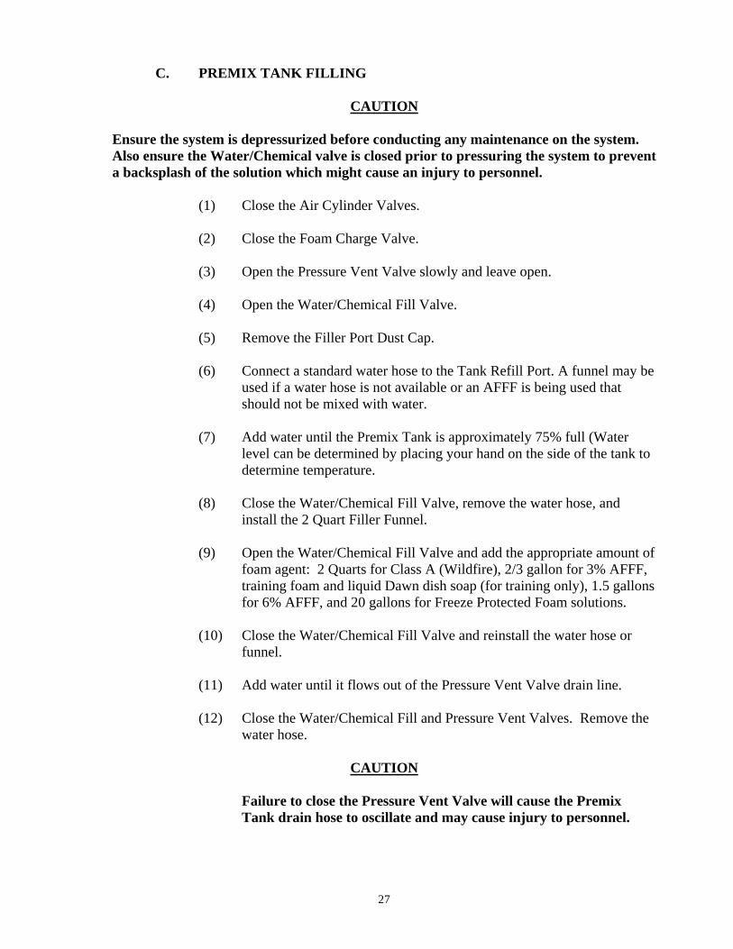
C. PREMIX TANK FILLING
CAUTION Ensure the system is depressurized before conducting any maintenance on the system. Also ensure the Water/Chemical valve is closed prior to pressuring the system to prevent a backsplash of the solution which might cause an injury to personnel.
(1) Close the Air Cylinder Valves.
(2) Close the Foam Charge Valve.
(3) Open the Pressure Vent Valve slowly and leave open.
(4) Open the Water/Chemical Fill Valve.
(5) Remove the Filler Port Dust Cap.
(6) Connect a standard water hose to the Tank Refill Port. A funnel may be used if a water hose is not available or an AFFF is being used that should not be mixed with water.
(7) Add water until the Premix Tank is approximately 75% full (Water
level can be determined by placing your hand on the side of the tank to determine temperature.
(8) Close the Water/Chemical Fill Valve, remove the water hose, and
install the 2 Quart Filler Funnel.
(9) Open the Water/Chemical Fill Valve and add the appropriate amount of foam agent: 2 Quarts for Class A (Wildfire), 2/3 gallon for 3% AFFF, training foam and liquid Dawn dish soap (for training only), 1.5 gallons for 6% AFFF, and 20 gallons for Freeze Protected Foam solutions.
(10) Close the Water/Chemical Fill Valve and reinstall the water hose or
funnel.
(11) Add water until it flows out of the Pressure Vent Valve drain line.
(12) Close the Water/Chemical Fill and Pressure Vent Valves. Remove the water hose.
CAUTION
Failure to close the Pressure Vent Valve will cause the Premix Tank drain hose to oscillate and may cause injury to personnel.

28
(13) Purge the solution from the Water/Chemical fill lines to prevent freezing by waiting 5 minutes for the solution to settle, opening both tank valves, and closing the valves. An alternate method is to use air to force the solution into the tank after the foam has settled.
(14) Annotate the type of foam and mixture ratio on a self-installed water
proof label applied in a visible area on the Premix tank.
(15) Replace the dust cap on the Fill Port. 5-7. SERVICING UNDER COLD CONDITIONS
A. Fill the Premix Tank with Freeze Protected Foam solution whenever the existing temperatures are below 32 degrees F. Freeze Protected Foam solutions should be used in the concentrate form and not diluted.
B. The procedures outlined in Paragraph 5-9 should be used for filling the Premix
Tank with the following exceptions:
(1) Remove the Pressure Vent Discharge hose, unscrew the JVC fitting from the valve, and push it one inch laterally. This procedure will provide adequate ventilation for the Premix Tank to be completely filled. Reattach the fitting and hose when the tank is full.
(2) It is recommended that the following procedure be used to purge the
Freeze Protected Foam solutions from the Water/Chemical Fill line after the Premix Tank has been filled to reduce the residual buildup:
(a) Close the Pressure Vent Valve and wait 5 minutes after filling
the tank for the solution to settle. (b) Apply air in the Water/Chemical Fill Valve line to force the
solution from the fill line into the Premix Tank. Do not use any water to wash the solution into the tank as the Freeze protected foam solutions cannot be diluted.
(c) Close the Water/Chemical and Pressure Vent Valves. (d) Wash any residual foam off the unit and place the unit in
service.
29
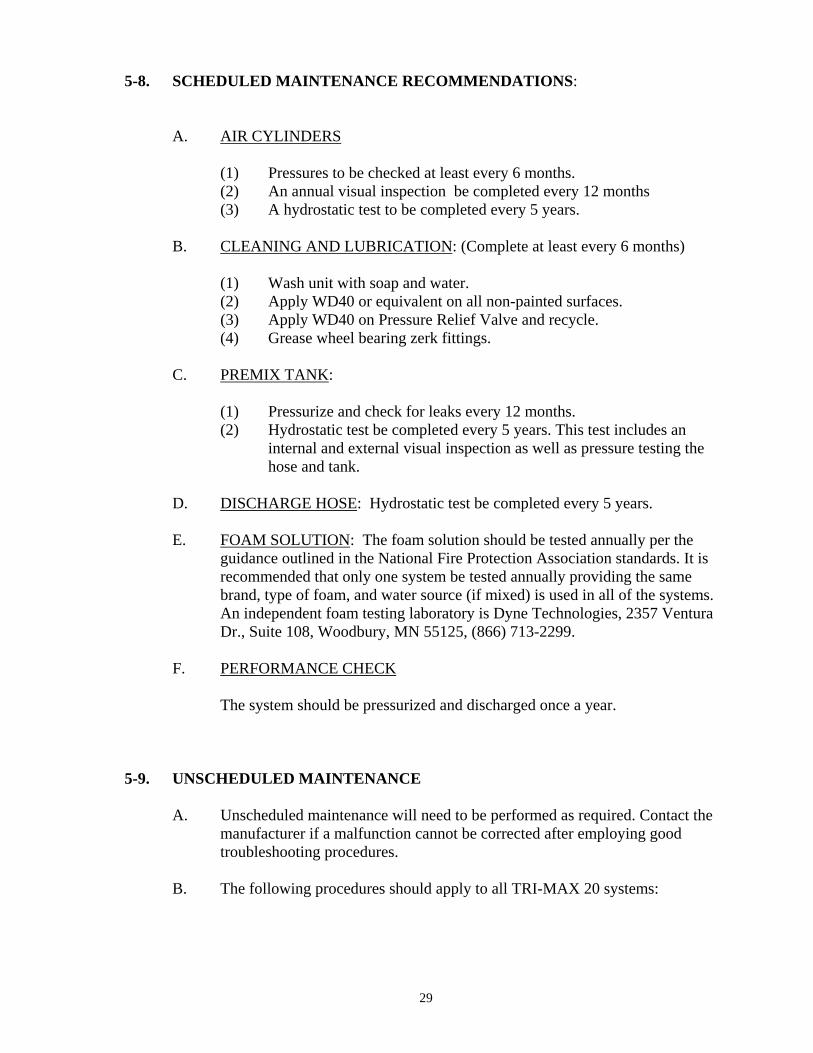
5-8. SCHEDULED MAINTENANCE RECOMMENDATIONS: A. AIR CYLINDERS (1) Pressures to be checked at least every 6 months. (2) An annual visual inspection be completed every 12 months (3) A hydrostatic test to be completed every 5 years. B. CLEANING AND LUBRICATION: (Complete at least every 6 months) (1) Wash unit with soap and water. (2) Apply WD40 or equivalent on all non-painted surfaces. (3) Apply WD40 on Pressure Relief Valve and recycle. (4) Grease wheel bearing zerk fittings. C. PREMIX TANK: (1) Pressurize and check for leaks every 12 months. (2) Hydrostatic test be completed every 5 years. This test includes an
internal and external visual inspection as well as pressure testing the hose and tank.
D. DISCHARGE HOSE: Hydrostatic test be completed every 5 years.
E. FOAM SOLUTION: The foam solution should be tested annually per the guidance outlined in the National Fire Protection Association standards. It is recommended that only one system be tested annually providing the same brand, type of foam, and water source (if mixed) is used in all of the systems. An independent foam testing laboratory is Dyne Technologies, 2357 Ventura Dr., Suite 108, Woodbury, MN 55125, (866) 713-2299.
F. PERFORMANCE CHECK
The system should be pressurized and discharged once a year.
5-9. UNSCHEDULED MAINTENANCE
A. Unscheduled maintenance will need to be performed as required. Contact the manufacturer if a malfunction cannot be corrected after employing good troubleshooting procedures.
B. The following procedures should apply to all TRI-MAX 20 systems:

30
(1) REPLACE AIR REGULATOR
NOTE The Aqua 415 Regulator is adjustable; however, the pressure is set at the factory at 150-160 psi. The adjustable control knob was removed and a non-adjusting knob was installed to preclude tampering. The adjustable control knob should be re-installed if a higher or lower pressure is desired.
REMOVAL PROCEDURE
1. Ensure air cylinder valves are closed. 2. Depressurize system by opening the pressure vent valve. Verify all
pressures read 0 psi. 3. Remove both ¼” hose lines from both the low (300 psi) and the high
(2000 psi) pressure gauges. 4. Remove both ¼” hose lines from the pressure in and out ports on the
air regulator. 5. Loosen both lock bolts in the lock ring. Remove adjustment knob from
the regulator, slide regulator back and out of ring. 6. Remove remaining hoses and fittings from the regulator and replace in
the same position on the new regulator.
INSTALLATION PROCEDURE
1. Slide the regulator into the ring and attach both ¼” in and out lines. using two wrenches to prevent damage to the hoses and regulator.
2. Reattach ¼” hoses to the low (300 psi) and the high (2000 psi) gauges. Tighten bolts in the ring to the regulator. 3. Re-install the non adjusting knob. 4. Charge the system by opening air cylinder valve. 5. Check for leaks using soap and water spray.
(2) REPLACE GAUGES
CAUTION
Ensure the system is depressurized before conducting any maintenance on the system.
(a) Ensure that the Air Cylinder Valve is closed.
(b) Depressurize the system by opening the Pressure Vent Valve. Ensure all pressure gauges read 0 psi.
(c) Remove gauge using proper wrenches. (d) Install new gauge.
(e) Charge the system by opening Air Cylinder Valve and check for leaks by squirting soap solution on connections.
(3) REPLACE PRESSURE RELIEF VALVE
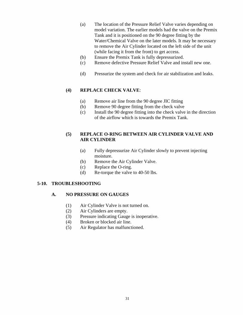
31
(a) The location of the Pressure Relief Valve varies depending on model variation. The earlier models had the valve on the Premix Tank and it is positioned on the 90 degree fitting by the Water/Chemical Valve on the later models. It may be necessary to remove the Air Cylinder located on the left side of the unit (while facing it from the front) to get access.
(b) Ensure the Premix Tank is fully depressurized. (c) Remove defective Pressure Relief Valve and install new one.
(d) Pressurize the system and check for air stabilization and leaks.
(4) REPLACE CHECK VALVE: (a) Remove air line from the 90 degree JIC fitting (b) Remove 90 degree fitting from the check valve
(c) Install the 90 degree fitting into the check valve in the direction of the airflow which is towards the Premix Tank.
(5) REPLACE O-RING BETWEEN AIR CYLINDER VALVE AND AIR CYLINDER
(a) Fully depressurize Air Cylinder slowly to prevent injecting
moisture. (b) Remove the Air Cylinder Valve. (c) Replace the O-ring.
(d) Re-torque the valve to 40-50 lbs. 5-10. TROUBLESHOOTING
A. NO PRESSURE ON GAUGES
(1) Air Cylinder Valve is not turned on. (2) Air Cylinders are empty. (3) Pressure indicating Gauge is inoperative. (4) Broken or blocked air line. (5) Air Regulator has malfunctioned.
32
B. FOAM DOES NOT DISCHARGE FROM HOSE
(1) Premix Tank is empty. (2) Air Cylinder is empty. (3) Air Cylinder is not turned on. (4) Foam Charge Valve is off. (5) Nozzle is in the off position. (6) Nozzle valve has malfunctioned. (7) Blockage in the dispensing hose. (8) Foam solution in Premix Tank is frozen. (9) Faulty check valve
C. AIRLINE LEAK
(1) Air hose fitting is loose or broken. (2) Air line is blocked or broken.
D. SYSTEM IS NOT FULLY DISCHARGING
(1) Insufficient volume of air in the Air Cylinder. (2) Foam Discharge Nozzle is not fully opening. (3) Foam Discharge Hose has a restriction. (4) Air Regulator has malfunctioned or is not properly adjusted (Arctic
Regulator only). (5) The solution is frozen or near freezing. (6) There is a blockage in the Premix Tank. (7) Defective check valve
E. SOLUTION IS RUNNING OUT OF PREMIX TANK OVERFLOW
Pressure vent valve is open. F. SOLUTION IS RUNNING OUT OF WATER/CHEMICAL FILL PORT
Water/Chemical Fill Valve is open. 5-11. STORAGE AND PROTECTION
A. A PMCS should be conducted if the system has been placed in storage prior to placing the unit in an operational status.
B. It is recommended that a weatherproof protective cover be used if the unit is
going to be positioned outside. Ultraviolet sunrays can cause long term damage to the hoses, tires, and gauges if the unit is not covered. Additionally, frozen rain and snow can restrict the movement of discharge hose. A heavy duty protective cover with reflective markings and frame securing devices is available from the manufacturer.


![New Presentatie Cafs Ieper [Compatibiliteitsmodus] · 2014. 7. 28. · Compressed Air Foam samengeperste lucht (van 30% tot 70% lucht tov water) Let’s talk about your fire protection](https://img.pdfslide.us/doc/110x75/605901d18f900b2b7b6106b3/new-presentatie-cafs-ieper-compatibiliteitsmodus-2014-7-28-compressed-air.jpg)