Embed Size (px)
Citation preview

Compound Miter Saw
Model C12LCH • C12LC • C12FCH
Handling instructions
Note:Before using this Electric Power Tool, carefully read through theseHANDLING INSTRUCTIONS to ensure efficient, safe operation. It isrecommended that these INSTRUCTIONS be kept readily availableas an important reference when using this power tool.

2
GENERAL OPERATIONAL PRECAUTIONS
WARNING! When using electric tools, basic safetyprecautions should always be followed to reduce the riskof fire, electric shock and personal injury, including thefollowing.Read all these instructions before operating this productand save these instructions.For safe operations:1. Keep work area clean. Cluttered areas and benches
invite injuries.2. Consider work area environment. Do not expose
power tools to rain. Do not use power tools in dampor wet locations. Keep work area well lit.Do not use power tools where there is risk to causefire or explosion.
3. Guard against electric shock. Avoid body contactwith earthed or grounded surfaces (e.g. pipes,radiators, ranges, refrigerators).
4. Keep children and infirm persons away. Do not letvisitors touch the tool or extension cord. All visitorsshould be kept away from work area.
5. Store idle tools. When not in use, tools should bestored in a dry, high or locked up place, out of reachof children and infirm persons.
6. Do not force the tool. It will do the job better andsafer at the rate for which it was intended.
7. Use the right tool. Do not force small tools orattachments to do the job of a heavy duty tool. Donot use tools for purposes not intended; for example,do not use circular saw to cut tree limbs or logs.
8. Dress properly. Do not wear loose clothing orjewelry, they can be caught in moving parts. Rubbergloves and non-skid footwear are recommendedwhen working outdoors. Wear protecting haircovering to contain long hair.
9. Use eye protection. Also use face or dust mask ifthe cutting operation is dusty.
10. Connect dust extraction equipment.Cutting operation by this compound miter saw mayproduce considerable amount of dust fromextraction duct on fixed guard.(Dust material: Wood or Aluminium)If devices are provided for the connection of dustextraction and collection facilities ensure these areconnected and properly used.
11. Do not abuse the cord. Never carry the tool by thecord or yank it to disconnect it from the receptacle.Keep the cord away from heat, oil and sharp edges.
12. Secure work. Use clamps or a vise to hold the work.It is safer than using your hand and it frees bothhands to operate tool.
13. Do not overreach. Keep proper footing and balanceat all times.
14. Maintain tools with care. Keep cutting tools sharpand clean for better and safer performance. Followinstructions for lubrication and changingaccessories. Inspect tool cords periodically and ifdamaged, have it repaired by authorized servicecenter. Inspect extension cords periodically andreplace, if damaged. Keep handles dry, clean, andfree from oil and grease.
15. Disconnect tools. When not in use, before servicing,and when changing accessories such as blades, bitsand cutters.
16. Remove adjusting keys and wrenches. Form thehabit of checking to see that keys and adjustingwrenches are removed from the tool before turningit on.
17. Avoid unintentional starting. Do not carry a plugged-in tool with a finger on the switch. Ensure switch isoff when plugging in.
18. Use outdoor extension leads. When tool is usedoutdoors, use only extension cords intended foroutdoor use.
19. Stay alert. Watch what you are doing. Use commonsense. Do not operate tool when you are tired.
20. Check damaged parts. Before further use of the tool,a guard or other part that is damaged should becarefully checked to determine that it will operateproperly and perform its intended function. Checkfor alignment of moving parts, free running ofmoving parts, breakage of parts, mounting and anyother conditions that may affect its operation. Aguard or other part that is damaged should beproperly repaired or replaced by an authorizedservice center unless otherwise indicated in thishandling instructions. Have defective switchesreplaced by an authorized service center. Do not usethe tool if the switch does not turn it on and off.
21. WarningThe use of any accessory or attachment, other thanthose recommended in this handling instructions,may present a risk of personal injury.
22. Have your tool repaired by a qualified person.This electric tool is in accordance with the relevantsafety requirements. Repairs should only be carriedout by qualified persons using original spare parts.Otherwise this may result in considerable dangerto the user.
PRECAUTIONS ON USING COMPOUND MITERSAW
1. Keep the floor area around the machine level. Wellmaintained and free of loose materials e.g. chipsand cut-offs.
2. Provide adequate general or localized lighting.3. Do not use power tools for applications other than
those specified in the handling instructions.4. Repairing must be done only by authorized service
facility. Manufacturer is not responsible for anydamages and injuries due to the repair by theunauthorized persons as well as the mishandling ofthe tool.
5. To ensure the designed operational integrity ofpower tools, do not remove installed covers orscrews.
6. Do not touch movable parts or accessories unlessthe power source has been disconnected.
7. Use your tool at lower input than specified on thenameplate; otherwise, the finish may be spoiled andworking efficiency reduced due to motor overload.
8. Do not wipe plastic parts with solvent. Solvents suchas gasoline, thinner, benzine, carbon tetrachloride,alcohol, may damage and crack plastic parts. Do notwipe them with such solvent. Clean plastic parts witha soft cloth lightly dampened with soapy water.
9. Use only original HITACHI replacement parts.10. This tool should only be disassembled for
replacement of carbon brushes.11. The exploded assembly drawing on this handling
instructions should be used only for authorizedservice facility.
12. Never cut ferrous metals or masonry.13. Adequate general or localized lighting is provided.
Stock and finished workpieces are located close tothe operators normal working position.
14. Wear suitable personal protective equipment whennecessary, this could include:Hearing protection to reduce the risk of inducedhearing loss.Eye protection to reduce the risk of injuring an eye.Respiratory protection to reduce the risk ofinhalation of harmful dust.

3
Gloves for handling saw blades (saw blades shallbe carried in a holder wherever practicable) andrough material.
15. The operator is adequately trained in the use,adjustment and operation of the machine.
16. Refrain from removing any cut-offs or other partsof the workpiece from the cutting area whilst themachine is running and the saw head is not in therest position.
17. Never use the compound miter saw with its lowerguard locked in the open position.
18. Ensure that the lower guard moves smoothly.19. Do not use the saw without guards in position, in
good working order and properly maintained.20. Use correctly sharpened saw blades. Observe the
maximum speed marked on the saw blade.21. Do not use saw blades which are damaged or
deformed.22. Do not use saw blades manufactured from high
speed steel.23. Use only saw blades recommended by HITACHI.24. The saw blades should be from 290 mm to 305 mm
external diameter ranges.25. Select the correct saw blade for the material to be
cut.26. Never operate the compound miter saw with the
saw blade turned upward or to the side.
27. Ensure that the workpiece is free of foreign mattersuch as nails.
28. Replace the table insert when worn.29. Do not use the saw to cut other than aluminium,
wood or similar materials.30. Do not use the saw to cut other materials than those
recommended by the manufacturer.31. Blade replacement procedure, including the method
for repositioning and a warning that this must becarried out correctly.
32. Connect the compound miter saw to a dustcollecting device when sawing wood.
33. Take care when slotting.34. When transporting or carrying the tool, do not grasp
the holder. Grasp the handle instead of the holder.35. Start cutting only after motor revolution reaches
maximum speed.36. Promptly cut OFF the switch when abnormality
observed.37. Shut off power and wait for saw blade to stop before
servicing or adjusting tool.38. During a miter or bevel cut the blade should not be
lifted until it has stopped rotation completely.39. Take all the possibility of residual risks in cutting
operation into your consideration, such as the laserradiation to your eyes, the inadvertent access tomoving parts on slide mechanical parts on machineand so on.
SPECIFICATIONS
* Be sure to check the nameplate on product as it is subject to change by areas.
63.5 mm × 200 mm0° or
98 mm × 155 mm
Miter 45° 63.5 mm × 140 mm
Bevel Left 45° 42 mm × 200 mm
Compound (Bevel Left 45°, Miter 45°) 42 mm × 140 mm
Saw Blade Dimensions (oD × iD × Thickness) 305 mm × 25.4 mm × 2.3 mm
Miter Cutting Angle Right and Left 0° – 52°
Bevel Cutting Angle Left –3° – 48°
Compound Cutting Angle Miter (Right and Left) 0° – 45°Bevel (Left) 0° – 45°
Voltage (by areas)* (110 V, 220 V, 230 V, 240 V)
Power Input* 1520 W
No-Load Speed 4000 / min
Machine Dimensions (Width × Depth × Height) 625 mm × 775 mm × 610 mm
Model C12LCH C12LC C12FCH
Weight (Net) 19.5 kg 19 kg
Digital Display Precision ±0.5° Yes Yes No
Laser Marker Yes No Yes
Maximum output Po<3 mW Class Laser Product
(Iambda) 654 nm
Laser medium Laser Diode
Max. CuttingCapacityHeight × Width
4
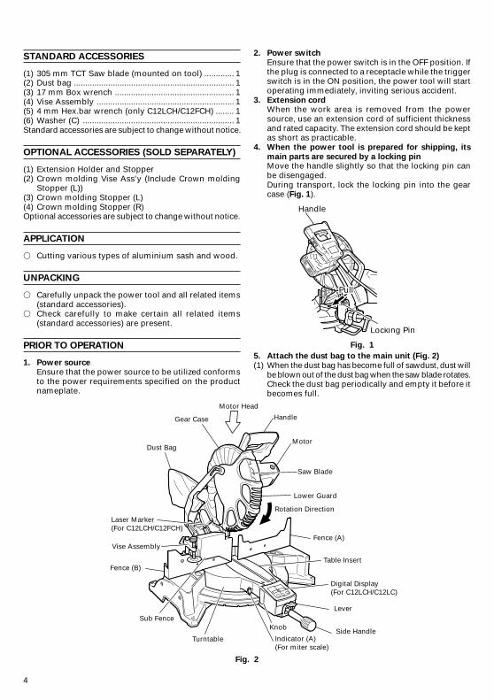
HandleGear Case
Motor Head
Dust BagMotor
Saw Blade
Lower Guard
Rotation Direction
Fence (A)
Fence (B)Table Insert
Digital Display(For C12LCH/C12LC)
Indicator (A)(For miter scale)
Lever
Side HandleTurntable
KnobSub Fence
Laser Marker(For C12LCH/C12FCH)
Vise Assembly
STANDARD ACCESSORIES
(1) 305 mm TCT Saw blade (mounted on tool) ............. 1(2) Dust bag ...................................................................... 1(3) 17 mm Box wrench .................................................... 1(4) Vise Assembly ............................................................ 1(5) 4 mm Hex.bar wrench (only C12LCH/C12FCH) ........ 1(6) Washer (C) .................................................................. 1Standard accessories are subject to change without notice.
OPTIONAL ACCESSORIES (SOLD SEPARATELY)
(1) Extension Holder and Stopper(2) Crown molding Vise Ass'y (Include Crown molding
Stopper (L))(3) Crown molding Stopper (L)(4) Crown molding Stopper (R)Optional accessories are subject to change without notice.
APPLICATION
� Cutting various types of aluminium sash and wood.
UNPACKING
� Carefully unpack the power tool and all related items(standard accessories).
� Check carefully to make certain all related items(standard accessories) are present.
PRIOR TO OPERATION
1. Power source
Ensure that the power source to be utilized conformsto the power requirements specified on the productnameplate.
2. Power switch
Ensure that the power switch is in the OFF position. Ifthe plug is connected to a receptacle while the triggerswitch is in the ON position, the power tool will startoperating immediately, inviting serious accident.
3. Extension cordWhen the work area is removed from the powersource, use an extension cord of sufficient thicknessand rated capacity. The extension cord should be keptas short as practicable.
4. When the power tool is prepared for shipping, its
main parts are secured by a locking pinMove the handle slightly so that the locking pin canbe disengaged.During transport, lock the locking pin into the gearcase (Fig. 1).
Fig. 1
5. Attach the dust bag to the main unit (Fig. 2)
(1) When the dust bag has become full of sawdust, dust willbe blown out of the dust bag when the saw blade rotates.Check the dust bag periodically and empty it before itbecomes full.
Handle
Locking Pin
PullPull
Fig. 2
5
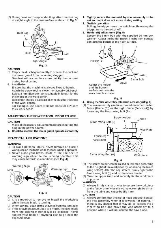
(2) During bevel and compound cutting, attach the dust bagat a right angle to the base surface as shown in Fig. 3.
Fig. 3
CAUTION� Empty the dust bag frequently to prevent the duct and
the lower guard from becoming clogged.Sawdust will accumulate more quickly than normalduring bevel cutting.
6. Installation
Ensure that the machine is always fixed to bench.Attach the power tool to a level, horizontal work bench.Select 8 mm diameter bolts suitable in length for thethickness of the work bench.Bolt length should be at least 35 mm plus the thicknessof the work bench.For example, use 8 mm × 60 mm bolts for a 25 mmthick work bench.
ADJUSTING THE POWER TOOL PRIOR TO USE
CAUTIONMake all necessary adjustments before inserting theplug in the power source.
1. Check to see that the lower guard operates smoothly
PRACTICAL APPLICATIONS
WARNING
� To avoid personal injury, never remove or place aworkpiece on the table while the tool is being operated.
� Never place your limbs inside of the line next towarning sign while the tool is being operated. Thismay cause hazardous conditions (see Fig. 4).
Fig. 4
CAUTION
� It is dangerous to remove or install the workpiecewhile the saw blade is turning.
� When sawing, clean off the shavings from the turntable.� If the shavings accumulate too much, the saw blade
from the cutting material will be exposed. Neversubject your hand or anything else to go near theexposed blade.
1. Tightly secure the material by vise assembly to be
cut so that it does not move during cutting
2. Switch operationPulling the trigger turns the switch on. Releasing thetrigger turns the switch off.
3. Holder (B) adjustment (Fig. 5)Loosen the 6 mm bolt with the supplied 10 mm boxwrench. Adjust the holder (B) until its bottom surfacecontacts the bench or the floor surface.
Fig. 5
4. Using the Vise Assembly (Standard accessory) (Fig. 6)
(1) The vise assembly can be mounted on either the leftfence {Fence (B)} or the right fence {Fence (A)} byloosening the 6 mm wing bolt (A).
Fig. 6
(2) The screw holder can be raised or lowered accordingto the height of the workpiece by loosening the 6 mmwing bolt (B). After the adjustment, firmly tighten the6 mm wing bolt (B) and fix the screw holder.
(3) Turn the upper knob and securely fix the workpiecein position.
WARNING
� Always firmly clamp or vise to secure the workpieceto the fence; otherwise the workpiece might be thrustfrom the table and cause bodily harm.
CAUTION
� Always confirm that the motor head does not contactthe vise assembly when it is lowered for cutting. Ifthere is any danger that it may do so, loosen the 6mm wing bolt and move the vise assembly to aposition where it will not contact the saw blade.
Dust Bag
Duct
Right AngleBase
Warning Sign LineWarning Sign
Line
MoveAdjust the holder until its bottom surface contacts the work bench surface.
Holder (B)
6 mm Bolt
6 mm Wing Bolt (B)
Screw Holder Knob
Vise Plate
Workpiece6 mm Wing Bolt (A)
Vise ShaftFence (B)
6
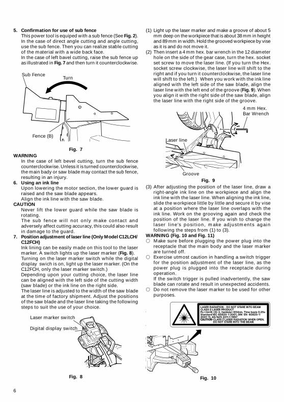
5. Confirmation for use of sub fence
This power tool is equiped with a sub fence (See Fig. 2).In the case of direct angle cutting and angle cutting,use the sub fence. Then you can realize stable cuttingof the material with a wide back face.In the case of left bavel cutting, raise the sub fence upas illustrated in Fig. 7 and then turn it counterclockwise.
Fig. 7
WARNING
In the case of left bevel cutting, turn the sub fencecounterclockwise. Unless it is turned counterclockwise,the main bady or saw blade may contact the sub fence,resulting in an injury.
6. Using an ink lineUpon lowering the motor section, the lower guard israised and the saw blade appears.Align the ink line with the saw blade.
CAUTION
Never lift the lower guard while the saw blade isrotating.The sub fence will not only make contact andadversely affect cutting accuracy, this could also resultin damage to the guard.
7. Position adjustment of laser line (Only Model C12LCH/
C12FCH)
Ink lining can be easily made on this tool to the lasermarker. A switch lights up the laser marker (Fig. 8).Turning on the laser marker switch while the digitaldisplay swich is on, light up the laser marker. (On theC12FCH, only the laser marker switch.)Depending upon your cutting choice, the laser linecan be aligned with the left side of the cutting width(saw blade) or the ink line on the right side.The laser line is adjusted to the width of the saw bladeat the time of factory shipment. Adjust the positionsof the saw blade and the laser line taking the followingsteps to suit the use of your choice.
Fig. 8
(1) Light up the laser marker and make a groove of about 5mm deep on the workpiece that is about 38 mm in heightand 89 mm in width. Hold the grooved workpiece by viseas it is and do not move it.
(2) Then insert a 4 mm hex. bar wrench in the 12 diameterhole on the side of the gear case, turn the hex. socketset screw to move the laser line. (If you turn the Hex.socket screw clockwise, the laser line will shift to theright and if you turn it counterclockwise, the laser linewill shift to the left.) When you work with the ink linealigned with the left side of the saw blade, align thelaser line with the left end of the groove (Fig. 9). Whenyou align it with the right side of the saw blade, alignthe laser line with the right side of the groove.
Fig. 9
(3) After adjusting the position of the laser line, draw aright-angle ink line on the workpiece and align theink line with the laser line. When aligning the ink line,slide the workpiece little by little and secure it by viseat a position where the laser line overlaps with theink line. Work on the grooving again and check theposition of the laser line. If you wish to change thelaser line’s position, make adjustments againfollowing the steps from (1) to (3).
WARNING (Fig. 10 and Fig. 11)� Make sure before plugging the power plug into the
receptacle that the main body and the laser markerare turned off.
� Exercise utmost caution in handling a switch triggerfor the position adjustment of the laser line, as thepower plug is plugged into the receptacle duringoperation.If the switch trigger is pulled inadvertently, the sawblade can rotate and result in unexpected accidents.
� Do not remove the laser marker to be used for otherpurposes.
Fig. 10
Sub FenceTurn
Fence (B)
Laser marker switch
Digital display switch
Laser line
4 mm Hex.Bar Wrench
Groove
7
Fig. 11
CAUTION
� Laser radiation - Do not stare into beam.� Laser radiation on work table. Do not stare into beam.
If your eye is exposed directly to the laser beam, itcan be hurt.
� Do not dismantle it.� Do not give strong impact to the laser marker (main
body of tool); otherwise, the position of a laser linecan go out of order, resulting in the damage of thelaser marker as well as a shortened service life.
� Keep the laser marker lit only during a cuttingoperation. Prolonged lighting of the laser marker canresult in a shortened service life.
� Use of controls or adjustments or performance ofprocedures other than those specified herein mayresult in hazardous radiation exposure.
NOTE� Perform cutting by overlapping the ink line with the
laser line.� When the ink line and the laser line are overlapped,
the strength and weakness of light will change,resulting in a stable cutting operation because youcan easily discern the conformity of lines. This ensuresthe minimum cutting errors.
� In outdoor or near-the-window operations, it maybecome difficult to observe the laser line due to thesunlight. Under such circumstances, move to a placethat is not directly under the sunlight and engage inthe operation.
� Do not tug on the cord behind the motor head or hookyour finger, wood and the like around it; otherwise,the cord may come off and the laser marker may notbe lit up.
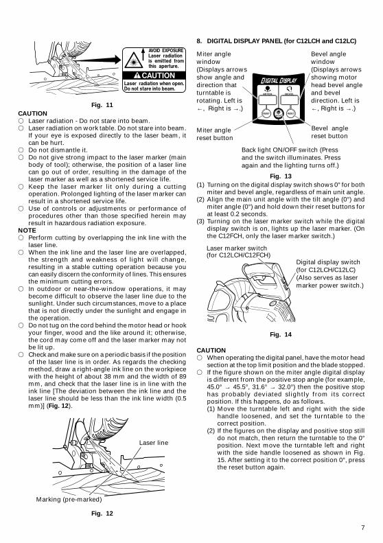
� Check and make sure on a periodic basis if the positionof the laser line is in order. As regards the checkingmethod, draw a right-angle ink line on the workpiecewith the height of about 38 mm and the width of 89mm, and check that the laser line is in line with theink line [The deviation between the ink line and thelaser line should be less than the ink line width (0.5mm)] (Fig. 12).
Fig. 12
8. DIGITAL DISPLAY PANEL (for C12LCH and C12LC)
Fig. 13
(1) Turning on the digital display switch shows 0° for bothmiter and bevel angle, regardless of main unit angle.
(2) Align the main unit angle with the tilt angle (0°) andmiter angle (0°) and hold down their reset buttons forat least 0.2 seconds.
(3) Turning on the laser marker switch while the digitaldisplay switch is on, lights up the laser marker. (Onthe C12FCH, only the laser marker switch.)
Fig. 14
CAUTION� When operating the digital panel, have the motor head
section at the top limit position and the blade stopped.� If the figure shown on the miter angle digital display
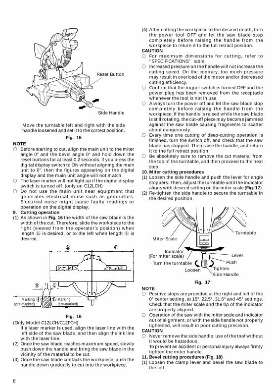
is different from the positive stop angle (for example,45.0° → 45.5°, 31.6° → 32.0°) then the positive stophas probably deviated slightly from its correctposition. If this happens, do as follows.(1) Move the turntable left and right with the side
handle loosened, and set the turntable to thecorrect position.
(2) If the figures on the display and positive stop stilldo not match, then return the turntable to the 0°position. Next move the turntable left and rightwith the side handle loosened as shown in Fig.15. After setting it to the correct position 0°, pressthe reset button again.
Laser line
Marking (pre-marked)
Miter angle window(Displays arrows show angle and direction that turntable is rotating. Left is ←, Right is →.)
Bevel angle window(Displays arrows showing motor head bevel angle and bevel direction. Left is ←, Right is →.)
Miter angle reset button
Bevel angle reset button
Back light ON/OFF switch (Press and the switch illuminates. Press again and the lighting turns off.)
Laser marker switch (for C12LCH/C12FCH)
Digital display switch (for C12LCH/C12LC)(Also serves as laser marker power switch.)
8
Move the turntable left and right with the sidehandle loosened and set it to the correct position.
Fig. 15
NOTE
� Before starting to cut, align the main unit to the miterangle 0° and the bevel angle 0° and hold down thereset buttons for at least 0.2 seconds. If you press thedigital display switch to ON without aligning the mainunit to 0°, then the figures appearing on the digitaldisplay and the main unit angle will not match.
� The laser marker will not light up if the digital displayswitch is turned off. (only on C12LCH)
� Do not use the main unit near equipment thatgenerates electrical noise such as generators.Electrical noise might cause faulty readings oroperation on the digital display.
9. Cutting operation(1) As shown in Fig. 16 the width of the saw blade is the
width of the cut. Therefore, slide the workpiece to theright (viewed from the operator’s position) whenlength is desired, or to the left when length isdesired.
Fig. 16
(Only Model C12LCH/C12FCH)If a laser marker is used, align the laser line with theleft side of the saw blade, and then align the ink linewith the laser line.
(2) Once the saw blade reaches maximum speed, slowlypush down the handle and bring the saw blade in thevicinity of the material to be cut.
(3) Once the saw blade contacts the workpiece, push thehandle down gradually to cut into the workpiece.
(4) After cutting the workpiece to the desired depth, turnthe power tool OFF and let the saw blade stopcompletely before raising the handle from theworkpiece to return it to the full retract position.
CAUTION
� For maximum dimensions for cutting, refer to“SPECIFICATIONS” table.
� Increased pressure on the handle will not increase thecutting speed. On the contrary, too much pressuremay result in overload of the motor and/or decreasedcutting efficiency.
� Confirm that the trigger switch is turned OFF and thepower plug has been removed from the receptaclewhenever the tool is not in use.
� Always turn the power off and let the saw blade stopcompletely before raising the handle from theworkpiece. If the handle is raised while the saw bladeis still rotating, the cut-off piece may become jammedagainst the saw blade causing fragments to scatterabout dangerously.
� Every time one cutting of deep-cutting operation isfinished, turn the switch off, and check that the sawblade has stopped. Then raise the handle, and returnit to the full retract position.
� Be absolutely sure to remove the cut material fromthe top of the turntable, and then proceed to the nextstep.
10. Miter cutting procedures
(1) Loosen the side handle and push the lever for anglestoppers. Then, adjust the turntable until the indicatoraligns with desired setting on the miter scale (Fig. 17).
(2) Re-tighten the side handle to secure the turntable inthe desired position.
Fig. 17
NOTE� Positive stops are provided at the right and left of the
0° center setting, at 15°, 22.5°, 31.6° and 45° settings.Check that the miter scale and the tip of the indicatorare properly aligned.
� Operation of the saw with the miter scale and indicatorout of alignment, or with the side handle not properlytightened, will result in poor cutting precision.
CAUTION
� Never remove the side handle; use of the tool withoutit would be hazardous.To prevent an accident or personal injury always firmlytighten the miter handle.
11. Bevel cutting procedures (Fig. 18)
(1) Loosen the clamp lever and bevel the saw blade tothe left.
Miter Scale
Turn the turntableLoosen
Side HandleTighten
Push
LeverIndicator
(For miter scale)
Turntable
Reset Button
Side Handle
Marking(pre-marked)
Marking(pre-marked)
9
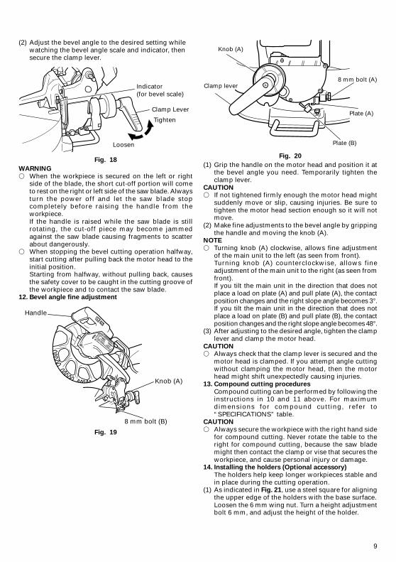
(2) Adjust the bevel angle to the desired setting whilewatching the bevel angle scale and indicator, thensecure the clamp lever.
Fig. 18
WARNING
� When the workpiece is secured on the left or rightside of the blade, the short cut-off portion will cometo rest on the right or left side of the saw blade. Alwaysturn the power off and let the saw blade stopcompletely before raising the handle from theworkpiece.If the handle is raised while the saw blade is stillrotating, the cut-off piece may become jammedagainst the saw blade causing fragments to scatterabout dangerously.
� When stopping the bevel cutting operation halfway,start cutting after pulling back the motor head to theinitial position.Starting from halfway, without pulling back, causesthe safety cover to be caught in the cutting groove ofthe workpiece and to contact the saw blade.
12. Bevel angle fine adjustment
Fig. 19
Fig. 20
(1) Grip the handle on the motor head and position it atthe bevel angle you need. Temporarily tighten theclamp lever.
CAUTION� If not tightened firmly enough the motor head might
suddenly move or slip, causing injuries. Be sure totighten the motor head section enough so it will notmove.
(2) Make fine adjustments to the bevel angle by grippingthe handle and moving the knob (A).
NOTE
� Turning knob (A) clockwise, allows fine adjustmentof the main unit to the left (as seen from front).Turning knob (A) counterclockwise, allows fineadjustment of the main unit to the right (as seen fromfront).If you tilt the main unit in the direction that does notplace a load on plate (A) and pull plate (A), the contactposition changes and the right slope angle becomes 3°.If you tilt the main unit in the direction that does notplace a load on plate (B) and pull plate (B), the contactposition changes and the right slope angle becomes 48°.
(3) After adjusting to the desired angle, tighten the clamplever and clamp the motor head.
CAUTION� Always check that the clamp lever is secured and the
motor head is clamped. If you attempt angle cuttingwithout clamping the motor head, then the motorhead might shift unexpectedly causing injuries.
13. Compound cutting procedures
Compound cutting can be performed by following theinstructions in 10 and 11 above. For maximumdimensions for compound cutting, refer to“SPECIFICATIONS” table.
CAUTION
� Always secure the workpiece with the right hand sidefor compound cutting. Never rotate the table to theright for compound cutting, because the saw blademight then contact the clamp or vise that secures theworkpiece, and cause personal injury or damage.
14. Installing the holders (Optional accessory)
The holders help keep longer workpieces stable andin place during the cutting operation.
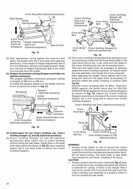
(1) As indicated in Fig. 21, use a steel square for aligningthe upper edge of the holders with the base surface.Loosen the 6 mm wing nut. Turn a height adjustmentbolt 6 mm, and adjust the height of the holder.
Handle
Knob (A)
8 mm bolt (B)
Clamp lever
Knob (A)
8 mm bolt (A)
Plate (A)
Plate (B)
Indicator(for bevel scale)
Clamp Lever
Tighten
Loosen
10
Fig. 21
(2) After adjustment, firmly tighten the wing nut andfasten the holder with the 6 mm knob bolt (optionalaccessory). If the length of Height Adjustment Bolt 6mm is insufficient, spread a thin plate beneath. Makesure the end of Height Adjustment Bolt 6 mm doesnot protrude from the holder.
15. Stopper for precision cutting (Stopper and holder are
optional accessory)The stopper facilitates continuous precision cuttingin lengths of 280 mm to 450 mm.To install the stopper, attach it to the holder with the6 mm wing bolt as shown in Fig. 22.
Fig. 22
16. Confirmation for use Crown molding vise, Crownmolding Stopper (L) and (R) (Optional accessory)
(1) Crown molding Stopper (L) and (R) (optionalaccessories) allow easier cuts of crown moldingwithout tilting the saw blade. lnstall them in the baseboth-sides side to be shown in Fig. 23. After insertingtighten the 6 mm knob bolts to secure the Crownmolding Stoppers.
Fig. 23
(2) The crown molding vise (B) (Optional accessory) canbe mounted on either the left fence (Fence (B)) or theright fence (Fence (A)). lt can unite with the slope ofthe crown molding and vice can be pressed down.Then turn the upper knob, as necessary, to securelyattach the crown molding in position. To raise or lowerthe vise assembly, first loosen the 6 mm wing bolt.After adjusting the height, firmly tighten the 6 mmwing bolt; then turn the upper knob, as necessary, tosecurely attach the crown molding in position (SeeFig 24).Position crown molding with its WALL CONTACTEDGE against the guide fence and its CEILINGCONTACT EDGE against the Crown molding Stoppersas shown in Fig. 24. Adjust the Crown moldingStoppers according to the size of the crown molding.Tighten the 6 mm wing bolt to secure the Crownmolding Stoppers.
Fig. 24
WARNING
� Always firmly clamp or vise to secure the crownmolding to the fence; otherwise the crown moldingmight be thrust from the table and cause bodily harm.Do not bevel cutting. The main body or saw blademay contact the sub fence, resulting in an injury.
CAUTION
� Always confirm that the motor head (see Fig. 2) doesnot contact the crown molding vise assembly when itis lowered for cutting. If there is any danger that itmay do so, loosen the 6 mm knob bolt and move thecrown molding vise assembly to a position where itwill not contact the saw blade.
Crown Molding Vise Ass’y (Optional accessory)
6 mmKnob Bolt
Fence (B)
6 mm WingBolt (A)
Crown molding
Knob
Crown Molding Stopper (L) (R)(Optional accessory)
Crown MoldingVise Ass’y(Optionalaccessories)
6 mm WingBolt
6 mm WingBolt
Crown Molding Stopper (L) (Optional accessories)
Crown MoldingStopper (R) (Optional accessories)6 mm Wing
Bolt
Steel SquareHolder(Optional accessory)
6 mm Wing Bolt (Optional accessory)
Base SurfaceHeight AdjustmentBolt 6 mm(Optional accessory)
6 mmWing Nut(Optionalaccessory)
WorkpieceStopper (Optional accessory)Holder(Optional accessory)
6 mm WingNut(Optionalaccessory)
Height Adjustment Bolt 6 mm(Optional accessory)6 mm Wing Bolt
(Optional accessory)
11
MOUNTING AND DISMOUNTING SAW BLADE
WARNING� To prevent an accident or personal injury, always turn off
the trigger switch and disconnect the power plug fromthe receptacle before removing or installing a blade.If cutting work is done in a state where the bolt is notsufficiently tightened, the bolt can get loose, the bladecan come off, and the lower guard can get damaged,resulting in injuries.Also, check that the bolts are properly tightened beforeplugging the power plug into the receptacle.
� If the bolts are attached or detached using tools otherthan the 17 mm box wrench (standard accessory),excessive or improperly tightening occurs, resultingin injury.
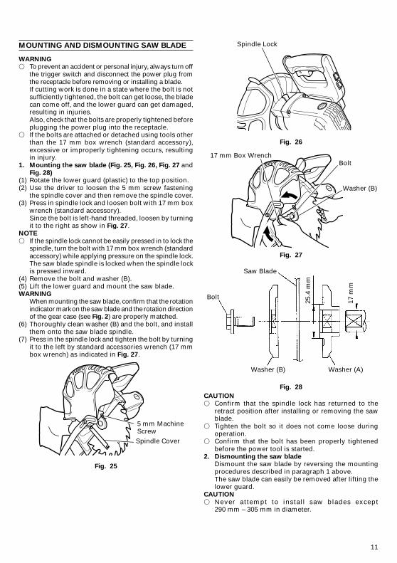
1. Mounting the saw blade (Fig. 25, Fig. 26, Fig. 27 andFig. 28)
(1) Rotate the lower guard (plastic) to the top position.(2) Use the driver to loosen the 5 mm screw fastening
the spindle cover and then remove the spindle cover.(3) Press in spindle lock and loosen bolt with 17 mm box
wrench (standard accessory).Since the bolt is left-hand threaded, loosen by turningit to the right as show in Fig. 27.
NOTE
� If the spindle lock cannot be easily pressed in to lock thespindle, turn the bolt with 17 mm box wrench (standardaccessory) while applying pressure on the spindle lock.The saw blade spindle is locked when the spindle lockis pressed inward.
(4) Remove the bolt and washer (B).(5) Lift the lower guard and mount the saw blade.WARNING
When mounting the saw blade, confirm that the rotationindicator mark on the saw blade and the rotation directionof the gear case (see Fig. 2) are properly matched.
(6) Thoroughly clean washer (B) and the bolt, and installthem onto the saw blade spindle.
(7) Press in the spindle lock and tighten the bolt by turningit to the left by standard accessories wrench (17 mmbox wrench) as indicated in Fig. 27.
Fig. 25
Fig. 26
Fig. 27
Fig. 28
CAUTION
� Confirm that the spindle lock has returned to theretract position after installing or removing the sawblade.
� Tighten the bolt so it does not come loose duringoperation.
� Confirm that the bolt has been properly tightenedbefore the power tool is started.
2. Dismounting the saw bladeDismount the saw blade by reversing the mountingprocedures described in paragraph 1 above.The saw blade can easily be removed after lifting thelower guard.
CAUTION
� Never attempt to install saw blades except290 mm – 305 mm in diameter.
Spindle Lock
17 mm Box WrenchBolt
Washer (B)
Saw Blade
Bolt
Washer (B) Washer (A)
17 m
m
25.4
mm
5 mm MachineScrewSpindle Cover
12
MAINTENANCE AND INSPECTION
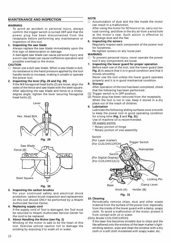
WARNINGTo avoid an accident or personal injury, alwaysconfirm the trigger switch is turned OFF and that thepower plug has been disconnected from thereceptacle before performing any maintenance orinspection of this tool.
1. Inspecting the saw bladeAlways replace the saw blade immediately upon thefirst sign of deterioration or damage.A damaged saw blade can cause personal injury anda worn saw blade can cause ineffective operation andpossible overload to the motor.
CAUTION� Never use a dull saw blade. When a saw blade is dull,
its resistance to the hand pressure applied by the toolhandle tends to increase, making it unsafe to operatethe power tool.
2. Inspecting the lever (Fig. 29 and Fig. 30)
If the M8 hexagonal head bolts (2) are loose, align thesides of the fence and saw blade with the steel square.After adjusting the saw blade and fence to a ninety-degree angle, tighten the lever securing hexagonalhead bolts (2).
Fig. 29
Fig. 30
3. Inspecting the carbon brushes
For your continued safety and electrical shockprotection, carbon brush inspection and replacementon this tool should ONLY be performed by a HitachiAuthorized Service Center.
4. Replacing supply cordIf the supply cord of Tool is damaged, the Tool mustbe returned to Hitachi Authorized Service Center forthe cord to be replaced.
5. About Handling the Motor (see Fig. 2)
Winding of the motor is said to be the heart of thistool. Exercise utmost caution not to damage thewinding by exposing it to wash oil or water.
NOTE
� Accumulation of dust and the like inside the motorcan result in a malfunction.After using the motor for 50 hours or so, carry out no-load running, and blow in the dry air from a wind holeat the motor's rear. Such action is effective todischarge dust and the like.
6. Inspecting the screws
Regularly inspect each component of the power toolfor looseness.Re-tighten screws on any loose part.
WARNING� To prevent personal injury, never operate the power
tool if any components are loose.7. Inspecting the lower guard for proper operation
Before each use of the tool, test the lower guard (seeFig. 2) to assure that it is in good condition and that itmoves smoothly.Never use the tool unless the lower guard operatesproperly and it is in good mechanical condition.
8. StorageAfter operation of the tool has been completed, checkthat the following has been performed:
(1) Trigger switch is in OFF position,(2) Power plug has been removed from the receptacle,
When the tool is not in use, keep it stored in a dryplace out of the reach of children.
9. Lubrication
Lubricate the following sliding surfaces once a monthto keep the power tool in good operating conditionfor a long time (Fig. 2 and Fig. 31).Use of machine oil is recommended.Oil supply points:* Rotary portion of hinge* Rotary portion of vise assembly
Fig. 31
10. CleaningPeriodically remove chips, dust and other wastematerial from the surface of the power tool, especiallyfrom the inside of the lower guard with a damp, soapycloth. To avoid a malfunction of the motor, protect itfrom contact with oil or water.
(Only Model C12LCH/C12FCH)If the laser line becomes invisible due to chips and thelike adhered onto the window of the laser marker's light-emitting section, wipe and clean the window with a drycloth or a soft cloth moistened with soapy water, etc.
Trigger Switch
Nameplate
Locking Pin
Clamp Lever
Holder (B)Knob (A)
Base
Switch (For Laser marker) (For C12LCH/C12FCH)
Switch (For Digital Display) (For C12LCH/C12LC)
Saw BladeFence (B)
Steel Square
Lever
Hex. Head Bolt

13
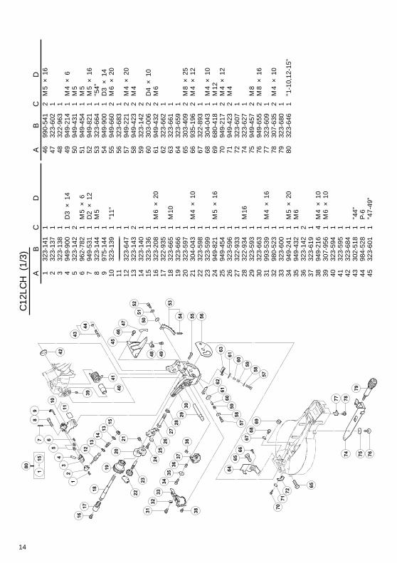
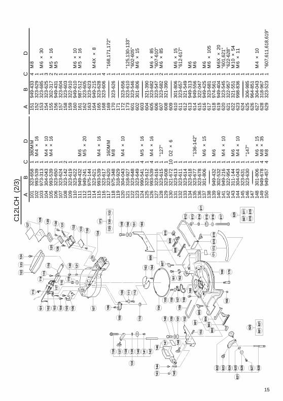
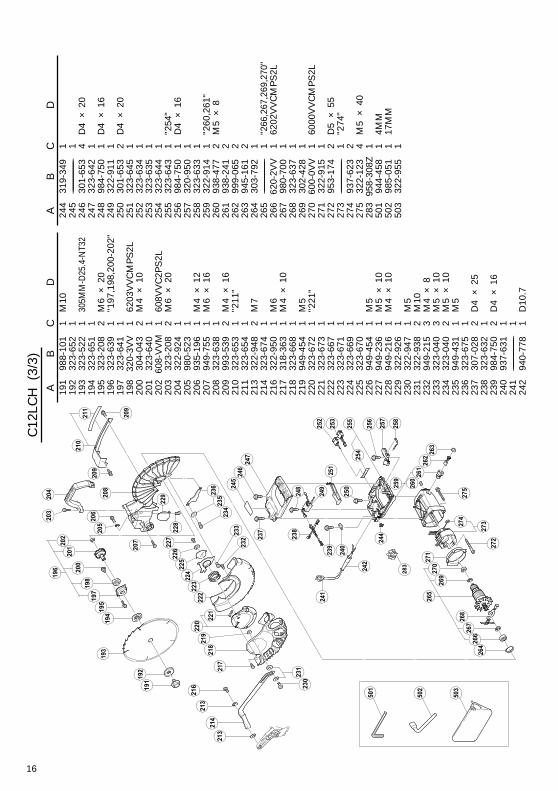
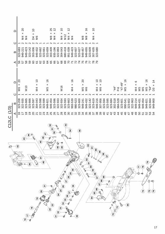
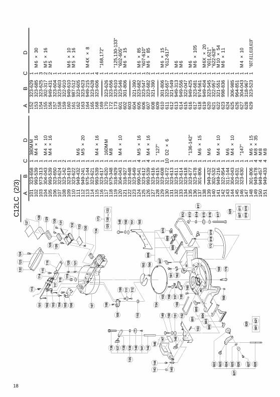
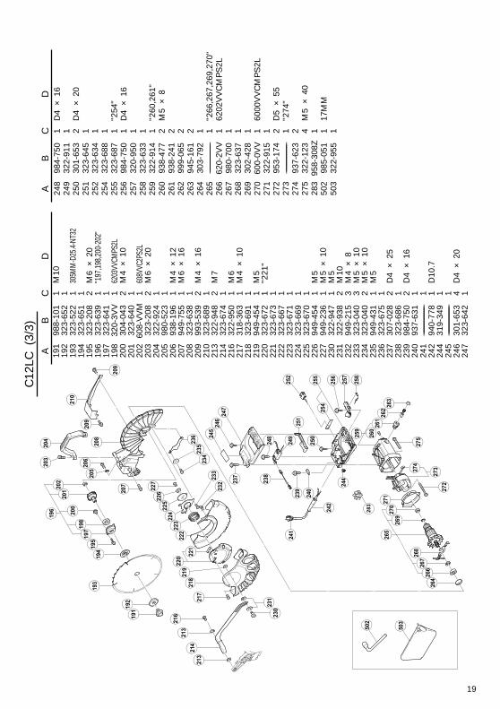
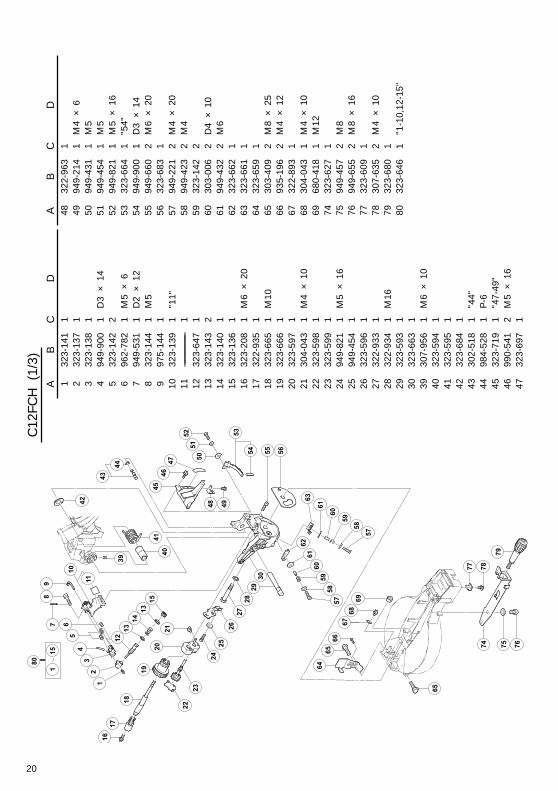
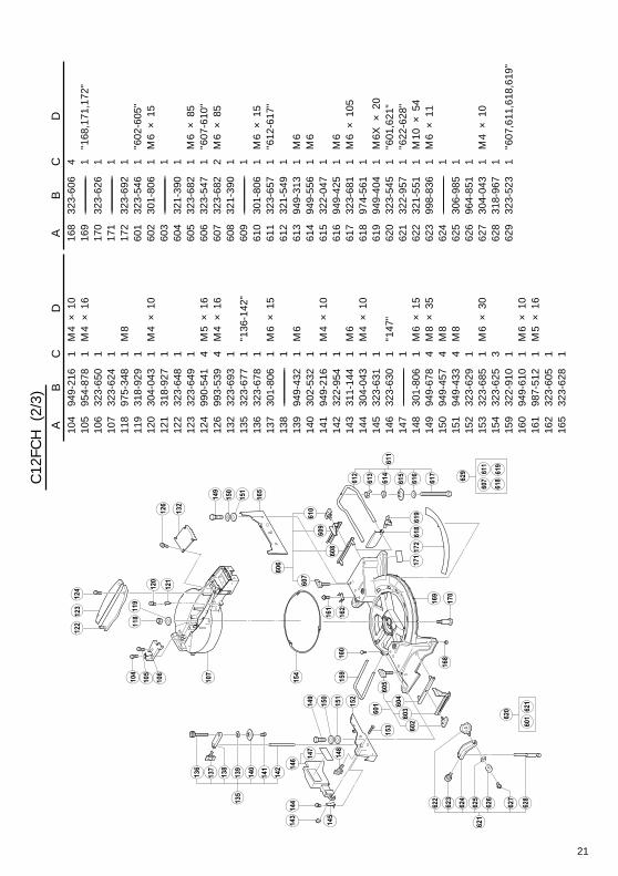
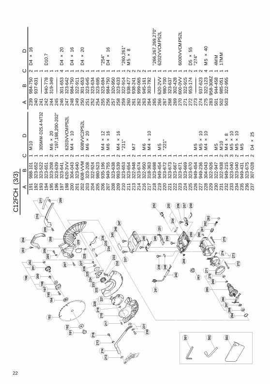
11. Service parts list
A : Item No.B : Code No.C : No. UsedD : Remarks
CAUTIONRepair, modification and inspection of Hitachi PowerTools must be carried out by a Hitachi AuthorizedService Center.Especially laser device should be maintained by theauthorized agent by laser manufacturer.Always assign the repair of laser device to HitachiAuthorized Service Center.This Parts List will be helpful if presented with thetool to the Hitachi Authorized Service Center whenrequesting repair or other maintenance.In the operation and maintenance of power tools, thesafety regulations and standards prescribed in eachcountry must be observed.
MODIFICATIONS
Hitachi Power Tools are constantly being improvedand modified to incorporate the latest technologicaladvancements.Accordingly, some parts (i.e. code numbers and/ordesign) may be changed without prior notice.
NOTE
Due to HITACHI’s continuing program of research anddevelopment the specifications herein are subject tochange without prior notice.
14
AB
CD
132
3-14
11
232
3-13
71
332
3-13
81
494
9-90
01
D3
× 14
532
3-14
22
696
2-78
21
M5
× 6
794
9-53
11
D2
× 12
832
3-14
41
M5
997
5-14
41
1032
3-13
91
"11"
11–––
––––––
––––––
––1
1232
3-64
71
1332
3-14
32
1432
3-14
01
1532
3-13
61
1632
3-20
81
M6
× 20
1732
2-93
51
1832
3-66
51
M10
1932
3-66
61
2032
3-59
71
2130
4-04
31
M4
× 10
2232
3-59
81
2332
3-59
91
2494
9-82
11
M5
× 16
2594
9-45
41
2632
3-59
61
2732
2-93
31
2832
2-93
41
M16
2932
3-59
31
3032
3-66
31
3199
3-53
91
M4
× 16
3298
0-52
31
3332
3-60
01
3494
9-24
11
M5
× 20
3594
9-43
21
M6
3632
3-14
22
3732
3-61
91
3894
9-21
64
M4
× 10
3930
7-95
61
M6
× 10
4032
3-59
41
4132
3-59
51
4232
3-68
41
4330
2-51
81
"44"
4498
4-52
81
P-6
4532
3-60
11
"47-
49"
AB
CD
4699
0-54
12
M5
× 16
4732
3-60
21
4832
2-96
31
4994
9-21
41
M4
× 6
5094
9-43
11
M5
5194
9-45
41
M5
5294
9-82
11
M5
× 16
5332
3-66
41
"54"
5494
9-90
01
D3
× 14
5594
9-66
02
M6
× 20
5632
3-68
31
5794
9-22
12
M4
× 20
5894
9-42
32
M4
5932
3-14
22
6030
3-00
62
D4
× 10
6194
9-43
22
M6
6232
3-66
21
6332
3-66
11
6432
3-65
91
6530
3-40
92
M8
× 25
6693
5-19
62
M4
× 12
6732
2-89
31
6830
4-04
31
M4
× 10
6968
0-41
81
M12
7094
9-21
72
M4
× 12
7194
9-42
32
M4
7232
3-60
71
7432
3-62
71
7594
9-45
72
M8
7694
9-65
52
M8
× 16
7732
3-60
91
7830
7-63
52
M4
× 10
7932
3-68
01
8032
3-64
61
"1-1
0,12
-15"
C12
LCH
(1/
3)
15
AB
CD
101
323-
658
138
0MM
102
993-
539
1M
4 ×
1610
397
3-31
31
104
304-
043
1M
4 ×
1010
599
3-53
91
M4
× 16
106
323-
650
110
732
3-62
41
108
323-
142
210
932
3-61
91
110
323-
622
111
194
9-43
21
M6
112
949-
241
1M
5 ×
2011
397
5-14
41
114
323-
621
111
599
3-53
91
M4
× 16
116
323-
617
111
732
3-62
01
160M
M11
897
5-34
81
M8
119
318-
929
112
030
4-04
31
M4
× 10
121
318-
927
112
232
3-64
81
123
323-
649
112
499
0-54
14
M5
× 16
125
323-
612
112
699
3-53
94
M4
× 16
127
323-
616
112
832
3-61
51
"127
"12
932
3-60
81
130
321-
672
10D
2 ×
613
132
3-61
31
132
323-
611
113
332
3-61
41
134
323-
618
113
532
3-67
71
"136
-142
"13
632
3-67
81
137
301-
806
1M
6 ×
1513
8–––
––––––
––1
139
949-
432
1M
614
030
2-53
21
141
949-
216
1M
4 ×
1014
232
2-95
41
143
311-
144
1M
614
430
4-04
31
M4
× 10
145
323-
631
114
632
3-63
01
"147
"14
7–––
––––––
––1
148
301-
806
1M
6 ×
1514
994
9-67
84
M8
× 35
150
949-
457
4M
8
AB
CD
151
949-
433
4M
815
232
3-62
91
153
323-
685
1M
6 ×
3015
432
3-62
53
155
302-
317
2M
5 ×
1615
694
9-43
12
M5
157
323-
604
115
832
3-60
31
159
322-
910
116
094
9-61
01
M6
× 10
161
987-
512
1M
5 ×
1616
232
3-60
51
163
323-
623
116
494
9-21
51
M4X
× 8
165
323-
628
116
832
3-60
64
169
––––––
––––––
–––––
1"1
68,1
71,1
72"
170
323-
626
117
1–––
––––––
––––––
––1
172
323-
656
117
332
3-61
01
"125
,130
-133
"60
132
3-54
61
"602
-605
"60
230
1-80
61
M6
× 15
603
––––––
––––––
–––––
160
432
1-39
01
605
323-
682
1M
6 ×
8560
632
3-54
71
"607
-610
"60
732
3-68
22
M6
× 85
608
321-
390
160
9–––
––––––
––––––
––1
610
301-
806
1M
6 ×
1561
132
3-65
71
"612
-617
"61
232
1-54
91
613
949-
313
1M
661
494
9-55
61
M6
615
322-
047
161
694
9-42
51
M6
617
323-
681
1M
6 ×
105
618
974-
561
161
994
9-40
41
M6X
× 2
062
032
3-54
51
"601
,621
"62
132
2-95
71
"622
-628
"62
232
1-55
11
M10
× 5
462
399
8-83
61
M6
× 11
624
––––––
––––––
–––––
162
530
6-98
51
626
964-
851
162
730
4-04
31
M4
× 10
628
318-
967
162
932
3-52
31
"607
,611
,618
,619
"
622
623
624
625
626
627
628
621
101
102
103
104
105
106
107
110
108
108
111
112
114
115
116
117
118 11
912
0
121
123
124
125
126
127
128
129
130
131
132
133
130
134
135
136
137
138
139
140
141
142
143
144
146
145
147
148
149
150
151
152
153
154
155
156
157
158
159
160
163
164
149
150
151
165
161
162
168
169
170
171
172
122
113
610
609
608
607
606
601
605
604
603
602
618
619
612
613
614
615
616
617
611
173
130
125
133
109
620
601
621
629 61
1
618
607
619
C12
LCH
(2/
3)
16
AB
CD
191
988-
101
1M
1019
232
3-65
21
193
323-
522
130
5MM
-D25
.4-N
T32
194
323-
651
119
532
3-20
82
M6
× 20
196
323-
639
1"1
97,1
98,2
00-2
02"
197
323-
641
119
832
0-3V
V1
6203
VV
CM
PS
2L20
030
4-04
32
M4
× 10
201
323-
640
120
260
8-V
VM
160
8VV
C2P
S2L
203
323-
208
2M
6 ×
2020
432
2-92
41
205
980-
523
120
693
5-19
61
M4
× 12
207
949-
755
1M
6 ×
1620
832
3-63
81
209
993-
539
2M
4 ×
1621
032
3-65
31
"211
"21
132
3-65
41
213
322-
948
2M
721
432
3-67
41
216
322-
950
1M
621
731
8-36
31
M4
× 10
218
323-
668
121
994
9-45
41
M5
220
323-
672
1"2
21"
221
323-
673
122
232
3-66
71
223
323-
671
122
432
3-66
91
225
323-
670
122
694
9-45
41
M5
227
949-
236
1M
5 ×
1022
894
9-21
61
M4
× 10
229
322-
926
123
032
2-94
71
M5
231
322-
938
2M
1023
294
9-21
53
M4
× 8
233
323-
040
3M
5 ×
1023
432
3-04
02
M5
× 10
235
949-
431
1M
523
632
3-67
51
237
307-
028
2D
4 ×
2523
832
3-63
21
239
984-
750
2D
4 ×
1624
093
7-63
11
241
––––––
––––––
–––––
124
294
0-77
81
D10
.7
AB
CD
244
319-
349
124
5–––
––––––
––––––
––1
246
301-
653
4D
4 ×
2024
732
3-64
21
248
984-
750
1D
4 ×
1624
932
2-91
11
250
301-
653
2D
4 ×
2025
132
3-64
51
252
323-
634
125
332
3-63
51
254
323-
644
125
532
3-64
31
"254
"25
698
4-75
01
D4
× 16
257
320-
950
125
832
3-63
31
259
322-
914
1"2
60,2
61"
260
938-
477
2M
5 ×
826
193
8-24
12
262
999-
065
226
394
5-16
12
264
303-
792
126
5–––
––––––
––––––
––1
"266
,267
,269
,270
"26
662
0-2V
V1
6202
VV
CM
PS
2L26
798
0-70
01
268
323-
637
126
930
2-42
81
270
600-
0VV
160
00V
VC
MP
S2L
271
322-
915
127
295
3-17
42
D5
× 55
273
––––––
––––––
–––––
1"2
74"
274
937-
623
227
532
2-12
34
M5
× 40
283
958-
308Z
150
194
4-45
81
4MM
502
985-
051
117
MM
503
322-
955
1
C12
LCH
(3/
3)
17
AB
CD
1632
3-20
81
M6
× 20
1732
2-93
51
1832
3-66
51
M10
1932
3-66
61
2032
3-59
71
2130
4-04
31
M4
× 10
2232
3-59
81
2332
3-59
91
2494
9-82
11
M5
× 16
2594
9-45
41
2632
3-59
61
2732
2-93
31
2832
2-93
41
M16
2932
3-59
31
3032
3-66
31
3199
3-53
91
M4
× 16
3298
0-52
31
3332
3-60
01
3494
9-24
11
M5
× 20
3594
9-43
21
M6
3632
3-14
22
3732
3-61
91
3894
9-21
64
M4
× 10
3930
7-95
61
M6
× 10
4032
3-59
41
4132
3-59
51
4232
3-68
41
4330
2-51
81
"44"
4498
4-52
81
P-6
4532
3-60
11
"47-
49"
4699
0-54
12
M5
× 16
4732
3-60
21
4832
2-96
31
4994
9-21
41
M4
× 6
5094
9-43
11
M5
5194
9-45
41
M5
5294
9-82
11
M5
× 16
5332
3-66
41
"54"
5494
9-90
01
D3
× 14
AB
CD
5632
3-68
31
5794
9-22
12
M4
× 20
5894
9-42
32
M4
5932
3-14
22
6030
3-00
62
D4
× 10
6194
9-43
22
M6
6232
3-66
21
6332
3-66
11
6432
3-65
91
6530
3-40
92
M8
× 25
6693
5-19
62
M4
× 12
6732
2-89
31
6830
4-04
31
M4
× 10
6968
0-41
81
M12
7095
1-03
92
M4
× 12
7194
9-42
32
M4
7232
3-60
71
7432
3-62
71
7594
9-45
72
M8
7694
9-65
52
M8
× 16
7732
3-60
91
7830
7-63
52
M4
× 10
7932
3-68
01
C12
LC (
1/3)
18
AB
CD
101
323-
658
138
0MM
102
993-
539
1M
4 ×
1610
397
3-31
31
104
304-
043
1M
4 ×
1010
599
3-53
91
M4
× 16
106
323-
650
110
732
3-62
41
108
323-
142
210
932
3-61
91
110
323-
622
111
194
9-43
21
M6
112
949-
241
1M
5 ×
2011
397
5-14
41
114
323-
621
111
599
3-53
91
M4
× 16
116
323-
617
111
732
3-62
01
160M
M11
897
5-34
81
M8
119
318-
929
112
030
4-04
31
M4
× 10
121
318-
927
112
232
3-64
81
123
323-
649
112
499
0-54
14
M5
× 16
125
323-
612
112
699
3-53
94
M4
× 16
127
323-
616
112
832
3-61
51
"127
"12
932
3-60
81
130
321-
672
10D
2 ×
613
132
3-61
31
132
323-
611
113
332
3-61
41
134
323-
618
113
532
3-67
71
"136
-142
"13
632
3-67
81
137
301-
806
1M
6 ×
1513
8–––
––––––
––––––
––1
139
949-
432
1M
614
030
2-53
21
141
949-
216
1M
4 ×
1014
232
2-95
41
143
311-
144
1M
614
430
4-04
31
M4
× 10
145
323-
631
114
632
3-63
01
"147
"14
7–––
––––––
––––––
––1
148
301-
806
1M
6 ×
1514
994
9-67
84
M8
× 35
150
949-
457
4M
815
194
9-43
34
M8
AB
CD
152
323-
629
115
332
3-68
51
M6
× 30
154
323-
625
315
530
2-31
72
M5
× 16
156
949-
431
2M
515
732
3-60
41
158
323-
603
115
932
2-91
01
160
949-
610
1M
6 ×
1016
198
7-51
21
M5
× 16
162
323-
605
116
332
3-62
31
164
949-
215
1M
4X ×
816
532
3-62
81
168
323-
606
416
9–––
––––––
––––––
––1
"168
,172
"17
032
3-62
61
172
323-
656
117
332
3-61
01
"125
,130
-133
"60
132
3-54
61
"602
-605
"60
230
1-80
61
M6
× 15
603
––––––
––––––
–––––
160
432
1-39
01
605
323-
682
1M
6 ×
8560
632
3-54
71
"607
-610
"60
732
3-68
22
M6
× 85
608
321-
390
160
9–––
––––––
––––––
––1
610
301-
806
1M
6 ×
1561
132
3-65
71
"612
-617
"61
232
1-54
91
613
949-
313
1M
661
494
9-55
61
M6
615
322-
047
161
694
9-42
51
M6
617
323-
681
1M
6 ×
105
618
974-
561
161
994
9-40
41
M6X
× 2
062
032
3-54
51
"601
,621
"62
132
2-95
71
"622
-628
"62
232
1-55
11
M10
× 5
462
399
8-83
61
M6
× 11
624
––––––
––––––
–––––
162
530
6-98
51
626
964-
851
162
730
4-04
31
M4
× 10
628
318-
967
162
932
3-52
31
"607
,611
,618
,619
"
C12
LC (
2/3)
19
AB
CD
191
988-
101
1M
1019
232
3-65
21
193
323-
522
130
5MM
-D25
.4-NT
3219
432
3-65
11
195
323-
208
2M
6 ×
2019
632
3-63
91
"197
,198
,200
-202
"19
732
3-64
11
198
320-
3VV
162
03VV
CMPS
2L20
030
4-04
32
M4
× 10
201
323-
640
120
260
8-V
VM
160
8VVC
2PS2
L20
332
3-20
82
M6
× 20
204
322-
924
120
598
0-52
31
206
938-
196
1M
4 ×
1220
794
9-75
51
M6
× 16
208
323-
638
120
999
3-53
92
M4
× 16
210
323-
689
121
332
2-94
82
M7
214
323-
674
121
632
2-95
01
M6
217
318-
363
1M
4 ×
1021
832
3-69
11
219
949-
454
1M
522
032
3-67
21
"221
"22
132
3-67
31
222
323-
667
122
332
3-67
11
224
323-
669
122
532
3-67
01
226
949-
454
1M
522
794
9-23
61
M5
× 10
230
322-
947
1M
523
132
2-93
82
M10
232
949-
215
3M
4 ×
823
332
3-04
03
M5
× 10
234
323-
040
2M
5 ×
1023
594
9-43
11
M5
236
323-
675
123
730
7-02
82
D4
× 25
238
323-
686
123
998
4-75
02
D4
× 16
240
937-
631
124
1–––
––––––
––––––
––1
242
940-
778
1D
10.7
244
319-
349
124
5–––
––––––
––––––
––1
246
301-
653
4D
4 ×
2024
732
3-64
21
AB
CD
248
984-
750
1D
4 ×
1624
932
2-91
11
250
301-
653
2D
4 ×
2025
132
3-64
51
252
323-
634
125
432
3-68
81
255
323-
687
1"2
54"
256
984-
750
1D
4 ×
1625
732
0-95
01
258
323-
633
125
932
2-91
41
"260
,261
"26
093
8-47
72
M5
× 8
261
938-
241
226
299
9-06
52
263
945-
161
226
430
3-79
21
265
––––––
––––––
–––––
1"2
66,2
67,2
69,2
70"
266
620-
2VV
162
02V
VC
MP
S2L
267
980-
700
126
832
3-63
71
269
302-
428
127
060
0-0V
V1
6000
VV
CM
PS
2L27
132
2-91
51
272
953-
174
2D
5 ×
5527
3–––
––––––
––––––
––1
"274
"27
493
7-62
32
275
322-
123
4M
5 ×
4028
395
8-30
8Z1
502
985-
051
117
MM
503
322-
955
1
C12
LC (
3/3)
20
AB
CD
132
3-14
11
232
3-13
71
332
3-13
81
494
9-90
01
D3
× 14
532
3-14
22
696
2-78
21
M5
× 6
794
9-53
11
D2
× 12
832
3-14
41
M5
997
5-14
41
1032
3-13
91
"11"
11–––
––––––
––––––
––1
1232
3-64
71
1332
3-14
32
1432
3-14
01
1532
3-13
61
1632
3-20
81
M6
× 20
1732
2-93
51
1832
3-66
51
M10
1932
3-66
61
2032
3-59
71
2130
4-04
31
M4
× 10
2232
3-59
81
2332
3-59
91
2494
9-82
11
M5
× 16
2594
9-45
41
2632
3-59
61
2732
2-93
31
2832
2-93
41
M16
2932
3-59
31
3032
3-66
31
3930
7-95
61
M6
× 10
4032
3-59
41
4132
3-59
51
4232
3-68
41
4330
2-51
81
"44"
4498
4-52
81
P-6
4532
3-71
91
"47-
49"
4699
0-54
12
M5
× 16
4732
3-69
71
AB
CD
4832
2-96
31
4994
9-21
41
M4
× 6
5094
9-43
11
M5
5194
9-45
41
M5
5294
9-82
11
M5
× 16
5332
3-66
41
"54"
5494
9-90
01
D3
× 14
5594
9-66
02
M6
× 20
5632
3-68
31
5794
9-22
12
M4
× 20
5894
9-42
32
M4
5932
3-14
22
6030
3-00
62
D4
× 10
6194
9-43
22
M6
6232
3-66
21
6332
3-66
11
6432
3-65
91
6530
3-40
92
M8
× 25
6693
5-19
62
M4
× 12
6732
2-89
31
6830
4-04
31
M4
× 10
6968
0-41
81
M12
7432
3-62
71
7594
9-45
72
M8
7694
9-65
52
M8
× 16
7732
3-60
91
7830
7-63
52
M4
× 10
7932
3-68
01
8032
3-64
61
"1-1
0,12
-15"
C12
FCH
(1/
3)
21
AB
CD
104
949-
216
1M
4 ×
1010
595
4-87
81
M4
× 16
106
323-
650
110
732
3-62
41
118
975-
348
1M
811
931
8-92
91
120
304-
043
1M
4 ×
1012
131
8-92
71
122
323-
648
112
332
3-64
91
124
990-
541
4M
5 ×
1612
699
3-53
94
M4
× 16
132
323-
693
113
532
3-67
71
"136
-142
"13
632
3-67
81
137
301-
806
1M
6 ×
1513
8–––
––––––
––––––
––1
139
949-
432
1M
614
030
2-53
21
141
949-
216
1M
4 ×
1014
232
2-95
41
143
311-
144
1M
614
430
4-04
31
M4
× 10
145
323-
631
114
632
3-63
01
"147
"14
7–––
––––––
––––––
––1
148
301-
806
1M
6 ×
1514
994
9-67
84
M8
× 35
150
949-
457
4M
815
194
9-43
34
M8
152
323-
629
115
332
3-68
51
M6
× 30
154
323-
625
315
932
2-91
01
160
949-
610
1M
6 ×
1016
198
7-51
21
M5
× 16
162
323-
605
116
532
3-62
81
AB
CD
168
323-
606
416
9–––
––––––
––––––
––1
"168
,171
,172
"17
032
3-62
61
171
––––––
––––––
–––––
117
232
3-69
21
601
323-
546
1"6
02-6
05"
602
301-
806
1M
6 ×
1560
3–––
––––––
––––––
––1
604
321-
390
160
532
3-68
21
M6
× 85
606
323-
547
1"6
07-6
10"
607
323-
682
2M
6 ×
8560
832
1-39
01
609
––––––
––––––
–––––
161
030
1-80
61
M6
× 15
611
323-
657
1"6
12-6
17"
612
321-
549
161
394
9-31
31
M6
614
949-
556
1M
661
532
2-04
71
616
949-
425
1M
661
732
3-68
11
M6
× 10
561
897
4-56
11
619
949-
404
1M
6X ×
20
620
323-
545
1"6
01,6
21"
621
322-
957
1"6
22-6
28"
622
321-
551
1M
10 ×
54
623
998-
836
1M
6 ×
1162
4–––
––––––
––––––
––1
625
306-
985
162
696
4-85
11
627
304-
043
1M
4 ×
1062
831
8-96
71
629
323-
523
1"6
07,6
11,6
18,6
19"
C12
FCH
(2/
3)
22
AB
CD
191
988-
101
1M
1019
232
3-65
21
193
323-
522
130
5MM
-D25
.4-N
T32
194
323-
651
119
532
3-20
82
M6
× 20
196
323-
639
1"1
97,1
98,2
00-2
02"
197
323-
641
119
862
0-3V
V1
6203
VV
CM
PS
2L20
030
4-04
32
M4
× 10
201
323-
640
120
260
8-V
VM
160
8VV
C2P
S2L
203
323-
208
2M
6 ×
2020
432
2-92
41
205
980-
523
120
693
5-19
61
M4
× 12
207
949-
755
1M
6 ×
1620
832
3-63
81
209
993-
539
2M
4 ×
1621
032
3-65
31
"211
"21
132
3-65
41
213
322-
948
2M
721
432
3-67
41
216
322-
950
1M
621
731
8-36
31
M4
× 10
218
323-
698
121
994
9-45
41
M5
220
323-
672
1"2
21"
221
323-
673
122
232
3-66
71
223
323-
671
122
432
3-66
91
225
323-
670
122
694
9-45
41
M5
227
949-
236
1M
5 ×
1022
830
4-04
31
M4
× 10
229
322-
926
123
032
2-94
71
M5
231
322-
938
2M
1023
294
9-21
53
M4
× 8
233
323-
040
3M
5 ×
1023
432
3-04
02
M5
× 10
235
949-
431
1M
523
632
3-67
51
237
307-
028
2D
4 ×
25
AB
CD
239
984-
750
2D
4 ×
1624
093
7-63
11
241
–––––––––––
124
294
0-77
81
D10
.724
431
9-34
91
245
–––––––––––
124
630
1-65
34
D4
× 20
247
323-
642
124
898
4-75
01
D4
× 16
249
322-
911
125
030
1-65
32
D4
× 20
251
323-
645
125
232
3-63
41
254
323-
695
125
532
3-69
41
"254
"25
698
4-75
01
D4
× 16
257
320-
950
125
832
3-63
31
259
322-
914
1"2
60,2
61"
260
938-
477
2M
5 ×
826
193
8-24
12
262
999-
065
226
394
5-16
12
264
303-
792
126
5–––––––––––
1"2
66,2
67,2
69,2
70"
266
620-
2VV
162
02V
VC
MP
S2L
267
980-
700
126
832
3-63
71
269
302-
428
127
060
0-0V
V1
6000
VV
CM
PS
2L27
132
2-91
51
272
953-
174
2D
5 ×
5527
3–––––––––––
1"2
74"
274
937-
623
227
532
2-12
34
M5
× 40
283
958-
308Z
150
194
4-45
81
4MM
502
985-
051
117
MM
503
322-
955
1
C12
FCH
(3/
3)

23

504Code No. C99132711Printed in China
Hitachi Koki Co., Ltd.


![Ryobi Miter saw TS1355LA_130_eng[1]](https://img.pdfslide.us/doc/110x75/577d38db1a28ab3a6b98a04e/ryobi-miter-saw-ts1355la130eng1.jpg)