Embed Size (px)
Citation preview
lable at ScienceDirect
Composites Science and Technology 166 (2018) 150e159
Contents lists avai
Composites Science and Technology
journal homepage: http: / /www.elsevier .com/locate /compscitech
Advanced carbon fiber composite out-of-autoclave laminatemanufacture via nanostructured out-of-oven conductive curing
Jeonyoon Lee a, Xinchen Ni a, Frederick Daso b, Xianghui Xiao c, Dale King d,Jose S�anchez G�omez e, Tamara Blanco Varela e, Seth S. Kessler f, Brian L. Wardle b, *
a Department of Mechanical Engineering, Massachusetts Institute of Technology, Cambridge, MA 02139, USAb Department of Aeronautics and Astronautics, Massachusetts Institute of Technology, Cambridge, MA 02139, USAc Advanced Photon Source, Argonne National Laboratory, Lemont, IL 60439, USAd Emerging Technologies & Concepts, Airbus Operations Ltd., Aerospace Avenue, Filton, Bristol BS34 7PA, UKe Materials & Processes, Airbus Operations S.L., Paseo John Lennon, Getafe 28906, Spainf Metis Design Corporation, 205 Portland Street, Boston, MA 02114, USA
a r t i c l e i n f o
Article history:Received 1 September 2017Received in revised form8 February 2018Accepted 19 February 2018Available online 26 February 2018
Keywords:Carbon nanotubesPrepregOut-of-AutoclaveConductive curingResistive heating
* Corresponding author.E-mail address: [email protected] (B.L. Wardle).
https://doi.org/10.1016/j.compscitech.2018.02.0310266-3538/© 2018 Elsevier Ltd. All rights reserved.
a b s t r a c t
Next-generation composite manufacturing processes are needed to overcome several limitations ofconventional manufacturing processes (e.g., high energy consumption). Here we explore, via experi-ments and modeling, the characteristics of the newly developed out-of-oven (OoO) curing technique thatcures a composite laminate via resistive heating of a carbon nanotube film. When compared to ovencuring of an aerospace-grade out-of-autoclave (OoA) carbon fiber prepreg advanced composite laminate,the OoO curing reduces energy consumption by over two orders of magnitude (14 vs. 0.1MJ). Thermo-physical and mechanical tests including differential scanning calorimetry (DSC), dynamic mechanicalanalysis (DMA), short beam shear (SBS), and ex-situ and in-situ double-edge notch tension (DENT)indicate that the physical and mechanical properties of OoO-cured laminates are equivalent to those ofoven-cured (baseline) laminates. In addition to energy savings, the OoO curing process has the potentialto reduce part-to-part variations through improved spatiotemporal temperature control.
© 2018 Elsevier Ltd. All rights reserved.
1. Introduction
Manufacturing of aerospace structural composites has tradi-tionally focused on using autoclaves to achieve high-qualityreproducible parts, including high fiber volume fractions and lowporosity [1,2]. Specifically, carbon fibers, which are pre-impregnated with a thermoset or thermoplastic resin to formprepreg sheets, are primarily used for autoclave processing tech-niques because of their ease of use and exceptional mechanicalperformance. However, manufacturing composites within anautoclave is accompanied by high acquisition and operation costsdue to the necessity of a specialized heated pressure vessel tosuppress the formation of voids. Furthermore, the capacity of au-toclaves limits the size and design of parts, and the production rateis primarily affected by autoclave availability. As a result, there hasbeen an increasing interest in the development of alternative
techniques. For example, the previous studies reportedmanufacturing approaches changing the method of heating such asmicrowave heating, induction heating, laser heating, and resistiveheating of carbon fibers or carbon nanotube (CNT) fillers in com-posites [3e6]. Additionally, specially-formulated and designedprepregs that can be cured in an oven (out-of-autoclave, or OoAprepregs) have been recently developed to remove the need of anautoclave [7,8].
OoA prepregs with oven curing have been introducedcommercially as an alternative to autoclave-cured prepregmanufacturing. In contrast to the autoclave prepregs, OoA prepregsdo not require the use of pressure vessels to achieve a void-freelaminate because of their formulation and unique structure; dryregions between resin-rich regions in OoA prepregs function asbuilt-in void extraction channels [8e15]. Thus, OoA prepregs can becuredwith conventional thermal ovens thereby allowing lower costmanufacturing than using autoclave-cured prepregs [16,17].Nonetheless, even the use of conventional ovens is not completelyideal from a manufacturing perspective. Heat transfer is still basedon convection, which leads to inefficiencies and to spatial gradients
J. Lee et al. / Composites Science and Technology 166 (2018) 150e159 151
in cure and stress due to convective-to-conductive interactionsbetween the oven gas medium (usually air) and the cure materials[18e20]. This also drives part-to-part variability, and fabrication isstill limited because of its fixed geometry despite advantages of anoven vs. an autoclave.
Given the limitations above, the concept of an out-of-oven(OoO) process has been proposed, which uses a CNT film as aheating element directly integrated into the surface of a lami-nate so that curing does not require any heating vessel orconvective medium [21]. However, while the previous studydemonstrated the concept of OoO curing along with degree-of-cure (DoC) comparisons, mechanical and physical properties ofOoO-cured composites have yet to be comprehensively evalu-ated, particularly properties dominated by interlaminar failure, akey area to evaluate for laminated composites [22]. To ourknowledge, the direct comparison between OoO and traditionalcuring from an energy consumption analysis has not been re-ported in the extant literature. In the current study, we comparethe OoO curing vs. oven curing using an OoA prepreg system,and find that the OoO curing enables highly efficientmanufacturing of composites while preserving the mechanicalproperties, particularly interlaminar strength, equivalent to theconventional oven method.
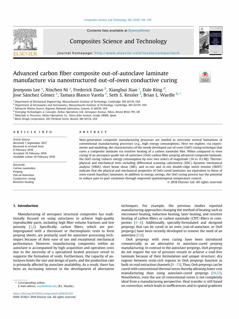
Fig. 1a illustrates the overview of the conventional oven vs. theOoO curing process. Conventional oven curing processes as well asautoclaves that use convective heating require the entire vessel
Vacuum Bag &Cure Materials
OoA Laminate
Air
Oven(a)
(b)
Heater
Air
Vacuum Bag &Cure Materials
Laminate
ThermalBarriers
ElectricalPower
ExothermicReaction
nevO
Heat Loss toEnvironment
Fig. 1. Comparison of oven and out-of-oven (OoO) manufacturing process for out-of-autoclaoven process. (b) Comparison of thermal equivalent circuit model of oven and out-of-ovenprocess provides direct conductive heat transfer to the laminate, whereas the oven process pmaterials.
volume to be heated, regardless of the geometry of the component.Therefore, as shown in Fig. 1b, the electrical power for resistiveheating should pass through several thermal barriers such as heatloss to the environment, the gas medium (here, air), and heating ofvacuum bagging and cure materials to heat up a laminate. As aconsequence, the energy consumption increases dramatically asthe size of the structure increases. In contrast, the OoO curing hasno thermal barriers between the heater and laminate, and thustransfers the heat via direct conduction because the CNT heater isinstalled on a surface of a laminate. Since the heat loss to theenvironment is connected to the heater in parallel, thermal insu-lation can suppress the heat loss, enabling most of electrical powerto go into the laminate from the heater. Additionally, because theCNT film has extremely low thermal mass due to its low density(�25 gsm), the electrical power can increase the temperature of alaminate immediately.
2. Material and methods
The characteristics of the OoO curing process were explored bytracking thermal responses and electrical power consumptionduring a cure cycle. To compare the mechanical and physicalproperties of OoO-cured composites with those of oven-curedcomposites, degree of cure analysis, short beam shear test, dy-namic mechanical analysis, and double-edge notch tensile testingwere performed.
Thermal InsulationOoA Laminate
CNT Heater
CNT FilmTeflon Film
Cu TapeTeflon Film
Vacuum Bag &Cure Materials
Out-of-Oven
Vacuum Bag &Cure Materials
Insulation
CNTHeater
Laminate
DirectContact
ElectricalPower
ExothermicReaction
nevO-fo-tuO
Heat Loss toEnvironment
ve laminate curing: (a) Overview of the physical differences between oven and out-of-process. The circuits are symmetric with respect to the laminate. Note that the OoOasses through thermal barriers including the oven medium (air), vacuum bag, and cure
J. Lee et al. / Composites Science and Technology 166 (2018) 150e159152
2.1. Composite fabrication and processing
In this study, Hexcel IM7/M56 OoA aerospace-grade unidirec-tional (UD) carbon fiber prepreg was used [23], which is designedto be processed with a vacuum-bag-only curing method. The pre-preg is nominally 394 gsm, and nominal cured ply thickness of thisprepreg was 253 mmwith a target of 58.8% Vf of carbon fiber in eachply. Considering the Standards used for the various experiments,and the field of view of synchrotron X-ray for in-situ tensile tests,eight plies (nominal laminate thickness of 2.02mm) were used forthe laminates quasi-isotropic layup of ½0=90=±45�S. Hexcel AS4/8552 unidirectional prepreg properties were used for the com-parison of energy consumption, because the ANSYS Composite CureSimulation (ACCS) provides the full engineering data of Hexcel AS4/8552 UD prepreg such as thermal conductivity, the exothermic heatof reaction for the cure modeling. The 16 plies of AS4/8552 UDprepreg were stacked up to match to the nominal thickness of thelaminates comprised of IM7/M56 prepreg; the nominal cured plythickness of AS4/8552 UD prepreg was 0.130mm, giving a nominallaminate thickness of 2.08mm, very close to the IM7/M56 nominalthickness of 2.02mm. As a resistive heater, a commercialized CNTfilm, Veelo HEAT from General Nano LLC. [24], was utilized for thiswork. The CNT film was composed of randomly oriented multi-walled CNTs, and was �40 mm thick, with an areal density of �25gsm and an isotropic sheet resistance of �5 U=,.
For the oven curing process, the recommended vacuum baggingprocedure from the prepreg manufacturer was followed [23,25]. Toensure the removal of air trapped during the hand lay-up process,vacuum debulking was performed on the full laminate at roomtemperature for 6 h. After the debulking process, the roundedlaminate edges were trimmed to ensure the laminate is re-breathable, a step necessitated by the OoA formulation of theprepreg, following manufacturer recommendations. Once a vac-uum bagwas prepared for the cure, the laminate and curematerialswas placed in a gravity convection oven (i.e., Lindberg/Blue M,GO1350A) for curing. During the cure cycle, the recommendedcuring condition in the technical data sheet was followed for eachprepreg system. Both prepreg systems are designed to have thesame temperature for the thermal process as follows: cure tem-perature of 110 �C with a hold time of 60min, and post cure tem-perature of 180 �C with a hold time of 120min; ramp rate at 3 �C/min.
For OoO curing, the cure setup was modified as a form ofconductive curing, similar to the previous study (See Fig. S1 for themodified vacuum bagging setup with a one-sided heater). Inparticular, thermal insulating blocks (i.e., MICROSIL MicroporousInsulation from ZIRCAR Ceramics Inc.) were installed to reduce heatloss to the environment. In addition, because one of the main goalsof this studywas to compare the physical properties of oven vs. OoOcuring, a Guaranteed Nonporous Teflon (GNPT) film was insertedbetween the heater and the surface of the laminate such that theOoO heater can be easily peeled off after cure. Such removal of theheating element is different from the previous study using a CNTnanocomposite heater; a conductive CNT polymer nanocompositewas permanently attached to the surface of the laminate with asurfacing film in the prior work [21,26]. During an OoO cure cycle, aDC power supply was connected to the two copper tape electrodesof the heater to control the input voltage to follow the specific curecycle [21,26]. For the feedback control, the input voltage was usedfor the system input, and the temperature of a CNT heater was thesystem output. Temperature of the CNT heater was measured via athermocouple (OMEGA Engineering fast-response K-type). Theinput voltage was controlled to make the temperature error lessthan 0.1 �C, while following the designated cure cycle. The vacuumbagging setup was placed on a lab bench. Input voltage, current,
and power consumption were recorded using digital multimetersembedded in the power supply (B&K Precision DC power supply9201).
2.2. Characteristics of oven and out-of-oven curing
To evaluate the energy consumption of an oven process and OoOprocess, the power consumption was measured during a cure cycleand compared with the model of the multi-physical curing processby ACCS. The transient thermal analysis was conducted to capturethermal responses within a laminate such as a temperature andheat flux. As mentioned above, a quasi-isotropic laminatecomprised of unidirectional layers of Hexcel AS4/8552 prepreg in a½0=90=±45�2S layup was used for finite element cure modeling dueto the full accessibility of engineering data. Each ply was modeledwith ten meshes to obtain results through the thickness of thelaminate. Note that the cure simulationwas conducted in 1D, whilethe experiment was under 3D.
For an oven process, a gravity convection oven was used in theexperiment and the model. The dimension and engineering datasuch as the amount of heat loss to the environment were adoptedto the model from the technical data sheet of the manufacturer[27]. The thermal analysis assumed that a vacuum bag and curematerials are surrounded by the heated air during a cure cycle.The power consumption was acquired by calculating the electricalpower of the heating elements. The convective heat transfer co-efficient was set at 15W/m�C at the surface of the vacuum bag,and the dry air of an oven was modeled as a lumped capacitancemodel. The heat flux from a laminate due to the exothermic re-action of the thermoset was included in the calculation. In theexperiment, the electrical power consumption was measureddirectly at the receptacle via a current probe (FLIR TA72). For theOoO process, we assumed that the temperature of a cure cycle wasapplied to the surface of a laminate because the CNT heatingcomponent is mounted directly on a surface of a laminate. Theengineering data of thermal insulation (density of 230 kg/m3,specific heat of 800 J/kg�C, and thermal conductivity of 0.019W/mK at 20 �C to 0.023W/mK at 200 �C with the assumption oflinearity) was introduced for the model. The experimental elec-trical power consumption was obtained by measuring the inputvoltage and current into the CNT heater mounted on laminate viaa DC power supply.
2.3. Degree of cure analysis
After the curing using the oven and OoO methods, differentialscanning calorimetry (DSC) was conducted using a Discovery DSC(TA instruments) to evaluate the degree of cure (DoC) of thelaminate. The dynamic DSC run was performed by scanning theheat flow from 40 �C to 300 �C at 5 �C/min ramp rate, based onASTM D7028. The DoC was estimated by comparing the area of theexothermic peak observed in the DSC curve of the heat-processedlaminate, also known as the heat of reaction, to that of an uncuredlaminate. The DSC specimens were taken from each layer of alaminate so that the through-thickness variance of the DoC couldbe assessed, particularly given the one-sided nature of the OoOcuring. For the DSC testing, eight plies of 60mm � 50mm IM7/M56 laminae were stacked unidirectionally by hand lay-up tech-nique, and release films were introduced to both the left and rightend of the laminate in between top, middle, and bottom layers foreasy separation after curing [21,28]. The release film preventsresin flow between layers. The procedures for oven and OoOcuring followed the same procedures described in the sectionabove.
J. Lee et al. / Composites Science and Technology 166 (2018) 150e159 153
2.4. Short beam shear testing
The short beam shear (SBS) test was conducted based on ASTMstandard D2344, which is also consistent with DIN EN2563, and isthe simplest test for interlaminar shear strength (ILSS). Thedimension of a specimenwas nominally 12mm � 4mm � 2mm (L� W � t), and these specimens were taken from the 120mm �120mm unidirectional laminates comprised of 8 plies of IM7/M56prepreg. Small angles (±2�) between the plies were introducedintentionally to avoid fiber nesting [29]. The cut laminate edgeswere polished with 800, 1200, and 2400 grit sandpapers to avoidrough or uneven surfaces which may result in pre-cracks followingthe Standard. As prescribed in the ASTM standard D2344 [30], athree-point bend fixture with a loading nose of 6mm, supports of3mm diameter steel cylinders, and the span length of 8mm wasutilized. During the tests, the force applied to the specimen wasmonitored at a rate of cross head movement of 1.0mm/min appliedby a Zwick/Roell Z010 mechanical testing machine. The short-beamstrength was then calculated using Eq. (1) as follows:
sSBS ¼ 0:75� Pfw� t
(1)
where Pf , w, and t are the load at the failure observed during thetest, the width, and the thickness of the specimen, respectively.
2.5. Dynamic mechanical analysis (DMA)
The specimen dimensions and testing procedure were carriedout based on the ASTM standard D7028. The Dynamic MechanicalAnalyzer used for the characterization of the composite laminateswas a TA Q800 DMA (TA Instruments). All DMA tests were con-ducted using a three-point bending fixture with a span of 50mm,which is ideal for composite materials due to its simpler stressdistribution than that induced in a single or double cantileverconfiguration and measurable strain for high modulus materials[31]. For DMA tests, an 8-ply unidirectional laminate of 120mm �120mm was cured by oven and OoO process, respectively. In thesame manner, the small angle between plies was used to preventthe fiber nesting. Four specimens of 60mm � 12mm � 2mm (L �W � t) taken from each oven-cured and OoO-cured laminate weretested in the temperature range from 40 �C to 300 �C at 2 �C/minheating rate, maximum strain of 50 mm, andmulti-frequency sweepof 1, 3.2,10, 30 Hz. The storagemodulus, lossmodulus, and tan deltawere obtained via DMA test, and the glass transition temperaturewas determined from the storage modulus curve. Among threedifferent ways to determine glass transition temperature, the tandelta curve was additionally used for determination of glass tran-sition temperature to conduct the most refined comparison of theoven-cured and the OoO-cured laminate with its clearness, eventhough the storage modulus curve is widely used because of itsconservativeness [31]. The estimation of the activation energy ismost likely to be consistent when the glass transition temperatureis determined by the tan delta peak [31e34]. The multi-frequencysweep results were analyzed to estimate the activation energy ofthe glass transition relaxation as an additional comparator of theoven vs. OoO manufacturing methods. The monitoring of the acti-vation energy is correlated to the modulus and compliance of acomposite at the end of the service life, and therefore is useful inassessing environmental exposure and aging of the material[32,34e37]. The estimation of the activation energy is based on theeffect of temperature on the frequency of molecular conformationalchanges in polymers [37,38]. Such phenomenon can be explainedby the Arrhenius relationship: the increase in frequency leads to theshift of the tan delta curve toward a higher temperature. The
activation energy can be estimated by obtaining the slope of the lnfvs. 1
Tgwith Eq. (2) as follows [31]:
DH ¼ �Rdðlnf Þd�1Tg
� (2)
where DH is the activation energy (kJ/mol) for the glass transitionrelaxation, R is the universal gas constant(J/mol K), f is the testingfrequency (Hz), and Tg is the glass transition temperature in Kelvin(K).
2.6. Double-edge notch tensile (DENT) test
To compare the tensile strength and the failure progression ofOoO-cured laminates with those of oven-cured laminates, ex-situand in-situ tensile testing with double-edge notch specimens wereconducted. For this test, a quasi-isotropic laminate (IM7/M56,½0=90=±45�S) of 120mm � 120mm was cured by eachmanufacturing method. The 1mm-radius double-edge notcheswere introduced into the 36mm-long and 4mm-wide specimensusing an abrasive waterjet so that the failure occurs within the X-ray field of view during in-situ tensile testing [39,40].
The CT5000 5kN in-situ tensile stage for mXCT (Deben UK Ltd.)was used as a load frame for both ex-situ and in-situ tensile testing.All tensile testing with the in-situ stage was conducted under0.3mm/min motor speed. The ultimate tensile strength (UTS) ofeach specimen was calculated with the area at the notch and themaximum load at failure. To evaluate the failure mode and pro-gression, the specimens were scanned via in-situ synchrotron X-raycomputed tomography (SRCT) prior to tensile loading and followedby scans at incrementally increasing stress range from 30% to 100%UTS in steps of 10%. The in-situ experiment was performed at thebeamline 2-BM of the Advanced Photon Source (APS), ArgonneNational Laboratory (ANL). An isotropic voxel size of 1.3 mm wasacquiredwith the X-ray beam energy of 22.7 keV and a 5� objectivelens. For each scan, 1500 2D projections were captured while aspecimenwas rotated in 180� via 2560� 2160 PCO.Edge 5.5 sCMOScamera. The exposure time for each projectionwas 100ms, and theprojection radiographs were reconstructed using TomoPy [41], anopen source Python based toolbox, and a reconstructed 3D volumeswere analyzed with the commercial visualization software, Avizo(FEI), to segment the features of interest such as matrix damage.
3. Results and discussion
Thermophysical andmechanical testing results are discussed forboth curing methods, followed by a failure progression study uti-lizing in-situ synchrotron computed tomography.
3.1. Characteristics of oven and out-of-oven curing
Fig. 2 shows the cure simulation and experimental results forthe oven and OoO curing process for the 2mm-thick 60mm �50mm laminate. As presented in Fig. 2a, the oven process showedan expected transient temperature response on the laminate sur-face due to the convective heat transfer, whereas the OoO processhad an immediate response by conductive heat transfer. Asmentioned in the Introduction, the convection coefficient in theheating vessel varies greatly due to uncontrolled factors that in-fluence gas flow dynamics, resulting in temperature gradients in alaminate [18e20]. Furthermore, if several parts are cured simulta-neously in a heating vessel, part-to-part variation may occur.However, because the OoO process directly controls the tempera-ture of each part, OoO curing has the potential to reduce part-to-
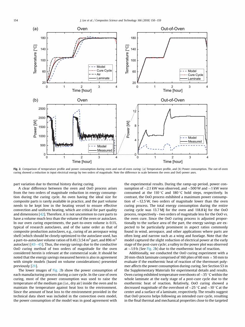
Fig. 2. Comparison of temperature profile and power consumption during oven and out-of-oven curing: (a) Temperature profile, and (b) Power consumption. The out-of-ovencuring showed a reduction in input electrical energy by two orders of magnitude. Note the difference in scale between the oven and OoO power axes.
J. Lee et al. / Composites Science and Technology 166 (2018) 150e159154
part variation due to thermal history during curing.A clear difference between the oven and OoO process arises
from the two orders of magnitude reduction in energy consump-tion during the curing cycle. An oven having the ideal size forcomposite parts is rarely available in practice, and the part volumeneeds to be kept low in the heating vessel to ensure effectiveconvection and uniform heating, which are critical for part qualityand dimensions [42]. Therefore, it is not uncommon to cure parts tohave a volume much less than the volume of the oven or autoclave.In our oven curing experiments, the part-to-oven volume is 0.1%,typical of research autoclaves, and of the same order as that ofcomposite production autoclaves, e.g., curing of an aerospace wingshell (which should be closely optimized to the autoclave used, hasa part-to-autoclave volume ration of 0.4% (3.54m3 part, and 896m3
autoclave) [43e45]. Thus, the energy savings due to the conductiveOoO curing method of two orders of magnitude for the ovenconsidered herein is relevant at the commercial scale. It should benoted that the energy savings measured herein is also in agreementwith simple models (based on volume considerations) presentedpreviously [21].
The lower images of Fig. 2b show the power consumption ofeach manufacturing process during a cure cycle. In the case of ovencuring, most of the power consumption was used to raise thetemperature of the medium gas (i.e., dry air) inside the oven and tomaintain the temperature against heat loss to the environment.Since the amount of heat loss to the environment provided in thetechnical data sheet was included in the convection oven model,the power consumption of the model was in good agreement with
the experimental results. During the ramp-up period, power con-sumption of �2.1 kW was observed, and �500W and �1 kW wereconsumed at the 110 �C and 180 �C hold steps, respectively. Incontrast, the OoO process exhibited a maximum power consump-tion of �12.5W, two orders of magnitude lower than the ovencuring process. The total energy consumption during the entirecuring cycle was 13.7MJ for the oven and 118.8 kJ for the OoOprocess, respectively - two orders of magnitude less for the OoO vs.the oven cure. Since the OoO curing process is adjusted propor-tionally to the surface area of the part, the energy savings are ex-pected to be particularly prominent in aspect ratios commonlyfound in wind, aerospace, and other applications where parts areoften long and narrow such as a wing and fuselage. Note that themodel captured the slight reduction of electrical power at the earlystage of the post-cure cycle; a valley in the power plot was observedat �1.9 h (See Fig. 2b) due to the exothermic heat of reaction.
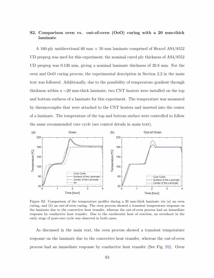
Additionally, we conducted the OoO curing experiment with a20mm-thick laminate comprised of 160 plies of 60mm� 50mm toevaluate if the exothermic heat of reaction of the thermoset poly-mer affects the power consumption during curing. See Section S3 inthe Supplementary Materials for experimental details and results.Oven curing exhibited temperature overshoots of�35 �Cwithin thewhole laminate at the early stage of a post-cure cycle due to theexothermic heat of reaction. Relatively, OoO curing showed adecreased magnitude of the overshoot of �25 �C and �10 �C at thecenter and a surface of a laminate, respectively. The results suggestthat OoO process helps following an intended cure cycle, resultingin the final thermal andmechanical properties close to the targeted
J. Lee et al. / Composites Science and Technology 166 (2018) 150e159 155
values. We observed that the exothermic heat of reaction from alaminate resulted in the �20min period in the early stage of post-cure cycle where any electrical power input was not required (SeeFig. S3 in the Supplementary Materials). Such a phenomenon in-dicates the possibility of further energy saving by recycling the heatof reaction of a laminate to cure itself.
3.2. Thermophysical properties
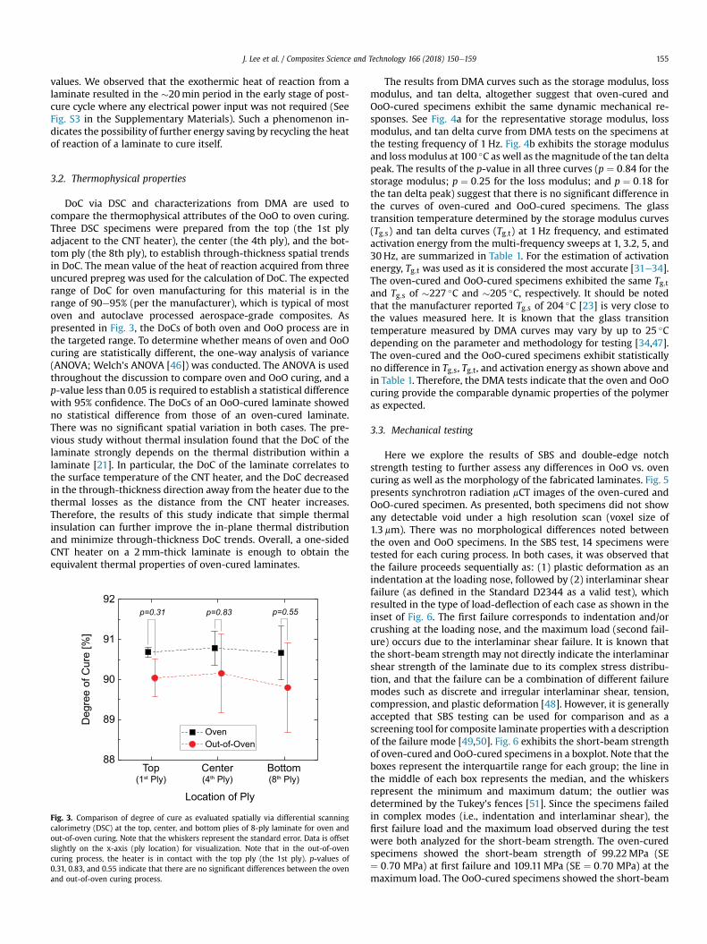
DoC via DSC and characterizations from DMA are used tocompare the thermophysical attributes of the OoO to oven curing.Three DSC specimens were prepared from the top (the 1st plyadjacent to the CNT heater), the center (the 4th ply), and the bot-tom ply (the 8th ply), to establish through-thickness spatial trendsin DoC. The mean value of the heat of reaction acquired from threeuncured prepreg was used for the calculation of DoC. The expectedrange of DoC for oven manufacturing for this material is in therange of 90e95% (per the manufacturer), which is typical of mostoven and autoclave processed aerospace-grade composites. Aspresented in Fig. 3, the DoCs of both oven and OoO process are inthe targeted range. To determine whether means of oven and OoOcuring are statistically different, the one-way analysis of variance(ANOVA; Welch's ANOVA [46]) was conducted. The ANOVA is usedthroughout the discussion to compare oven and OoO curing, and ap-value less than 0.05 is required to establish a statistical differencewith 95% confidence. The DoCs of an OoO-cured laminate showedno statistical difference from those of an oven-cured laminate.There was no significant spatial variation in both cases. The pre-vious study without thermal insulation found that the DoC of thelaminate strongly depends on the thermal distribution within alaminate [21]. In particular, the DoC of the laminate correlates tothe surface temperature of the CNT heater, and the DoC decreasedin the through-thickness direction away from the heater due to thethermal losses as the distance from the CNT heater increases.Therefore, the results of this study indicate that simple thermalinsulation can further improve the in-plane thermal distributionand minimize through-thickness DoC trends. Overall, a one-sidedCNT heater on a 2mm-thick laminate is enough to obtain theequivalent thermal properties of oven-cured laminates.
Fig. 3. Comparison of degree of cure as evaluated spatially via differential scanningcalorimetry (DSC) at the top, center, and bottom plies of 8-ply laminate for oven andout-of-oven curing. Note that the whiskers represent the standard error. Data is offsetslightly on the x-axis (ply location) for visualization. Note that in the out-of-ovencuring process, the heater is in contact with the top ply (the 1st ply). p-values of0.31, 0.83, and 0.55 indicate that there are no significant differences between the ovenand out-of-oven curing process.
The results from DMA curves such as the storage modulus, lossmodulus, and tan delta, altogether suggest that oven-cured andOoO-cured specimens exhibit the same dynamic mechanical re-sponses. See Fig. 4a for the representative storage modulus, lossmodulus, and tan delta curve from DMA tests on the specimens atthe testing frequency of 1 Hz. Fig. 4b exhibits the storage modulusand loss modulus at 100 �C as well as themagnitude of the tan deltapeak. The results of the p-value in all three curves (p ¼ 0:84 for thestorage modulus; p ¼ 0:25 for the loss modulus; and p ¼ 0:18 forthe tan delta peak) suggest that there is no significant difference inthe curves of oven-cured and OoO-cured specimens. The glasstransition temperature determined by the storage modulus curves(Tg;s) and tan delta curves (Tg;t) at 1 Hz frequency, and estimatedactivation energy from the multi-frequency sweeps at 1, 3.2, 5, and30 Hz, are summarized in Table 1. For the estimation of activationenergy, Tg;t was used as it is considered the most accurate [31e34].The oven-cured and OoO-cured specimens exhibited the same Tg;tand Tg;s of �227 �C and �205 �C, respectively. It should be notedthat the manufacturer reported Tg;s of 204 �C [23] is very close tothe values measured here. It is known that the glass transitiontemperature measured by DMA curves may vary by up to 25 �Cdepending on the parameter and methodology for testing [34,47].The oven-cured and the OoO-cured specimens exhibit statisticallyno difference in Tg;s, Tg;t, and activation energy as shown above andin Table 1. Therefore, the DMA tests indicate that the oven and OoOcuring provide the comparable dynamic properties of the polymeras expected.
3.3. Mechanical testing
Here we explore the results of SBS and double-edge notchstrength testing to further assess any differences in OoO vs. ovencuring as well as the morphology of the fabricated laminates. Fig. 5presents synchrotron radiation mCT images of the oven-cured andOoO-cured specimen. As presented, both specimens did not showany detectable void under a high resolution scan (voxel size of1.3 mm). There was no morphological differences noted betweenthe oven and OoO specimens. In the SBS test, 14 specimens weretested for each curing process. In both cases, it was observed thatthe failure proceeds sequentially as: (1) plastic deformation as anindentation at the loading nose, followed by (2) interlaminar shearfailure (as defined in the Standard D2344 as a valid test), whichresulted in the type of load-deflection of each case as shown in theinset of Fig. 6. The first failure corresponds to indentation and/orcrushing at the loading nose, and the maximum load (second fail-ure) occurs due to the interlaminar shear failure. It is known thatthe short-beam strength may not directly indicate the interlaminarshear strength of the laminate due to its complex stress distribu-tion, and that the failure can be a combination of different failuremodes such as discrete and irregular interlaminar shear, tension,compression, and plastic deformation [48]. However, it is generallyaccepted that SBS testing can be used for comparison and as ascreening tool for composite laminate properties with a descriptionof the failure mode [49,50]. Fig. 6 exhibits the short-beam strengthof oven-cured and OoO-cured specimens in a boxplot. Note that theboxes represent the interquartile range for each group; the line inthe middle of each box represents the median, and the whiskersrepresent the minimum and maximum datum; the outlier wasdetermined by the Tukey's fences [51]. Since the specimens failedin complex modes (i.e., indentation and interlaminar shear), thefirst failure load and the maximum load observed during the testwere both analyzed for the short-beam strength. The oven-curedspecimens showed the short-beam strength of 99.22MPa (SE¼ 0:70 MPa) at first failure and 109.11MPa (SE ¼ 0:70 MPa) at themaximum load. The OoO-cured specimens showed the short-beam
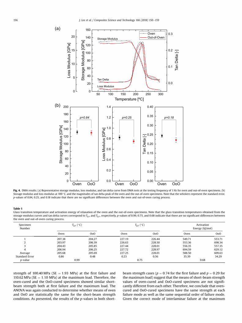
Fig. 4. DMA results. (a) Representative storage modulus, loss modulus, and tan delta curve from DMA tests at the testing frequency of 1 Hz for oven and out-of-oven specimens. (b)Storage modulus and loss modulus at 100 �C, and the magnitudes of tan delta peak of the oven and the out-of-oven specimens. Note that the whiskers represent the standard error.p-values of 0.84, 0.25, and 0.18 indicate that there are no significant differences between the oven and out-of-oven curing process.
Table 1Glass transition temperature and activation energy of relaxation of the oven and the out-of-oven specimens. Note that the glass transition temperatures obtained from thestorage modulus curves and tan delta curves correspond to Tg;s and Tg;t , respectively. p-values of 0.99, 0.75, and 0.68 indicate that there are no significant differences betweenthe oven and out-of-oven curing process.
SpecimenNumber
Tg;s (�C) Tg;t (�C) ActivationEnergy (kJ/mol)
Oven OoO Oven OoO Oven OoO
1 207.38 204.27 227.19 226.44 549.71 553.712 203.97 206.39 226.63 228.50 553.36 698.343 204.43 205.85 227.44 228.01 556.35 557.354 206.94 206.25 227.72 228.97 694.59 629.12
Average 205.68 205.69 227.25 228.01 588.50 609.63Standard Error 0.86 0.48 0.23 0.56 35.39 34.29
p-value 0.99 0.75 0.68
J. Lee et al. / Composites Science and Technology 166 (2018) 150e159156
strength of 100.40MPa (SE ¼ 1:93 MPa) at the first failure and110.62MPa (SE ¼ 1:10 MPa) at the maximum load. Therefore, theoven-cured and the OoO-cured specimens showed similar short-beam strength both at first failure and the maximum load. TheANOVA was again conducted to determine whether means of ovenand OoO are statistically the same for the short-beam strengthconditions. As presented, the results of the p-values in both short-
beam strength cases (p ¼ 0:74 for the first failure and p ¼ 0:29 forthe maximum load) suggest that the means of short-beam strengthvalues of oven-cured and OoO-cured specimens are not signifi-cantly different from each other. Therefore, we conclude that oven-cured and OoO-cured specimens have the same strength at eachfailure mode as well as the same sequential order of failure mode.Given the correct mode of interlaminar failure at the maximum
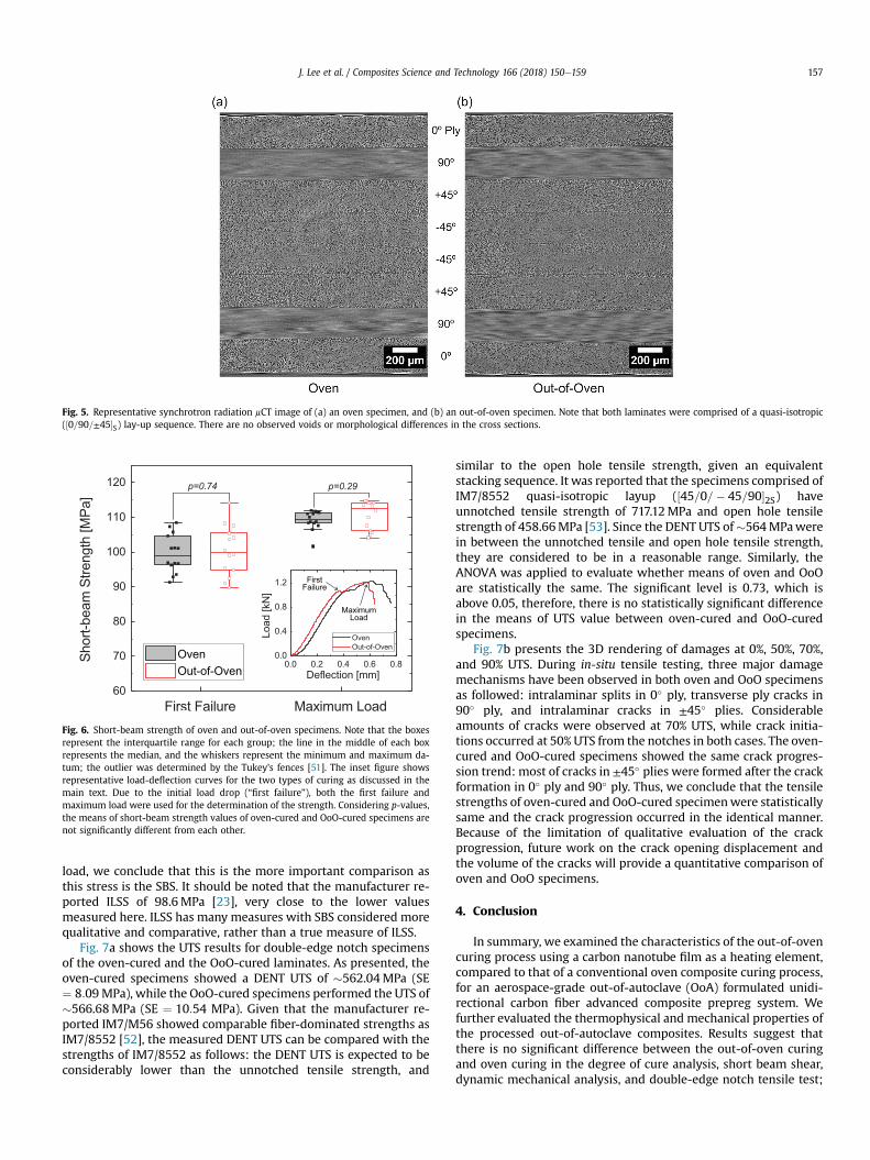
Fig. 5. Representative synchrotron radiation mCT image of (a) an oven specimen, and (b) an out-of-oven specimen. Note that both laminates were comprised of a quasi-isotropic(½0=90=±45�S) lay-up sequence. There are no observed voids or morphological differences in the cross sections.
Fig. 6. Short-beam strength of oven and out-of-oven specimens. Note that the boxesrepresent the interquartile range for each group; the line in the middle of each boxrepresents the median, and the whiskers represent the minimum and maximum da-tum; the outlier was determined by the Tukey's fences [51]. The inset figure showsrepresentative load-deflection curves for the two types of curing as discussed in themain text. Due to the initial load drop (“first failure”), both the first failure andmaximum load were used for the determination of the strength. Considering p-values,the means of short-beam strength values of oven-cured and OoO-cured specimens arenot significantly different from each other.
J. Lee et al. / Composites Science and Technology 166 (2018) 150e159 157
load, we conclude that this is the more important comparison asthis stress is the SBS. It should be noted that the manufacturer re-ported ILSS of 98.6MPa [23], very close to the lower valuesmeasured here. ILSS has many measures with SBS considered morequalitative and comparative, rather than a true measure of ILSS.
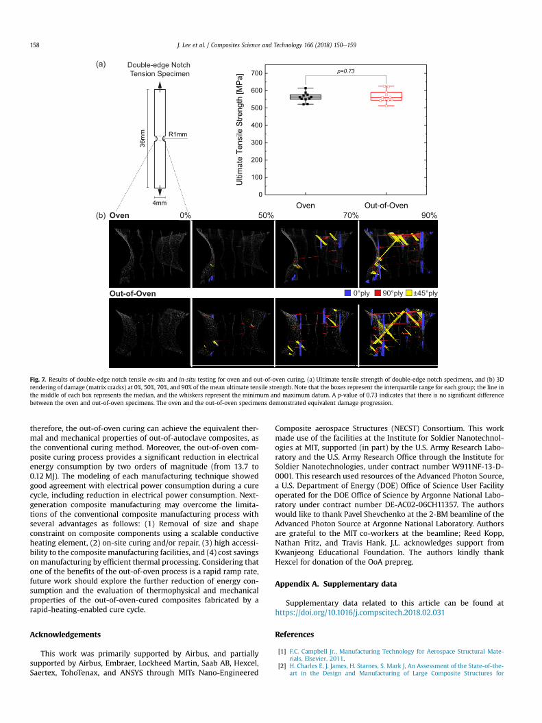
Fig. 7a shows the UTS results for double-edge notch specimensof the oven-cured and the OoO-cured laminates. As presented, theoven-cured specimens showed a DENT UTS of �562.04MPa (SE¼ 8:09MPa), while the OoO-cured specimens performed the UTS of�566.68MPa (SE ¼ 10:54 MPa). Given that the manufacturer re-ported IM7/M56 showed comparable fiber-dominated strengths asIM7/8552 [52], the measured DENT UTS can be compared with thestrengths of IM7/8552 as follows: the DENT UTS is expected to beconsiderably lower than the unnotched tensile strength, and
similar to the open hole tensile strength, given an equivalentstacking sequence. It was reported that the specimens comprised ofIM7/8552 quasi-isotropic layup (½45=0=� 45=90�2S) haveunnotched tensile strength of 717.12MPa and open hole tensilestrength of 458.66MPa [53]. Since the DENT UTS of�564MPawerein between the unnotched tensile and open hole tensile strength,they are considered to be in a reasonable range. Similarly, theANOVA was applied to evaluate whether means of oven and OoOare statistically the same. The significant level is 0.73, which isabove 0.05, therefore, there is no statistically significant differencein the means of UTS value between oven-cured and OoO-curedspecimens.
Fig. 7b presents the 3D rendering of damages at 0%, 50%, 70%,and 90% UTS. During in-situ tensile testing, three major damagemechanisms have been observed in both oven and OoO specimensas followed: intralaminar splits in 0� ply, transverse ply cracks in90� ply, and intralaminar cracks in ±45� plies. Considerableamounts of cracks were observed at 70% UTS, while crack initia-tions occurred at 50% UTS from the notches in both cases. The oven-cured and OoO-cured specimens showed the same crack progres-sion trend: most of cracks in ±45� plies were formed after the crackformation in 0� ply and 90� ply. Thus, we conclude that the tensilestrengths of oven-cured and OoO-cured specimenwere statisticallysame and the crack progression occurred in the identical manner.Because of the limitation of qualitative evaluation of the crackprogression, future work on the crack opening displacement andthe volume of the cracks will provide a quantitative comparison ofoven and OoO specimens.
4. Conclusion
In summary, we examined the characteristics of the out-of-ovencuring process using a carbon nanotube film as a heating element,compared to that of a conventional oven composite curing process,for an aerospace-grade out-of-autoclave (OoA) formulated unidi-rectional carbon fiber advanced composite prepreg system. Wefurther evaluated the thermophysical and mechanical properties ofthe processed out-of-autoclave composites. Results suggest thatthere is no significant difference between the out-of-oven curingand oven curing in the degree of cure analysis, short beam shear,dynamic mechanical analysis, and double-edge notch tensile test;
36m
m
4mm
R1mm
0% 50% 70% 90%
0°ply 90°ply ±45°ply
Oven
Out-of-Oven
(a)
(b)
Double-edge Notch Tension Specimen
Fig. 7. Results of double-edge notch tensile ex-situ and in-situ testing for oven and out-of-oven curing. (a) Ultimate tensile strength of double-edge notch specimens, and (b) 3Drendering of damage (matrix cracks) at 0%, 50%, 70%, and 90% of the mean ultimate tensile strength. Note that the boxes represent the interquartile range for each group; the line inthe middle of each box represents the median, and the whiskers represent the minimum and maximum datum. A p-value of 0.73 indicates that there is no significant differencebetween the oven and out-of-oven specimens. The oven and the out-of-oven specimens demonstrated equivalent damage progression.
J. Lee et al. / Composites Science and Technology 166 (2018) 150e159158
therefore, the out-of-oven curing can achieve the equivalent ther-mal and mechanical properties of out-of-autoclave composites, asthe conventional curing method. Moreover, the out-of-oven com-posite curing process provides a significant reduction in electricalenergy consumption by two orders of magnitude (from 13.7 to0.12MJ). The modeling of each manufacturing technique showedgood agreement with electrical power consumption during a curecycle, including reduction in electrical power consumption. Next-generation composite manufacturing may overcome the limita-tions of the conventional composite manufacturing process withseveral advantages as follows: (1) Removal of size and shapeconstraint on composite components using a scalable conductiveheating element, (2) on-site curing and/or repair, (3) high accessi-bility to the composite manufacturing facilities, and (4) cost savingson manufacturing by efficient thermal processing. Considering thatone of the benefits of the out-of-oven process is a rapid ramp rate,future work should explore the further reduction of energy con-sumption and the evaluation of thermophysical and mechanicalproperties of the out-of-oven-cured composites fabricated by arapid-heating-enabled cure cycle.
Acknowledgements
This work was primarily supported by Airbus, and partiallysupported by Airbus, Embraer, Lockheed Martin, Saab AB, Hexcel,Saertex, TohoTenax, and ANSYS through MITs Nano-Engineered
Composite aerospace Structures (NECST) Consortium. This workmade use of the facilities at the Institute for Soldier Nanotechnol-ogies at MIT, supported (in part) by the U.S. Army Research Labo-ratory and the U.S. Army Research Office through the Institute forSoldier Nanotechnologies, under contract number W911NF-13-D-0001. This research used resources of the Advanced Photon Source,a U.S. Department of Energy (DOE) Office of Science User Facilityoperated for the DOE Office of Science by Argonne National Labo-ratory under contract number DE-AC02-06CH11357. The authorswould like to thank Pavel Shevchenko at the 2-BM beamline of theAdvanced Photon Source at Argonne National Laboratory. Authorsare grateful to the MIT co-workers at the beamline; Reed Kopp,Nathan Fritz, and Travis Hank. J.L. acknowledges support fromKwanjeong Educational Foundation. The authors kindly thankHexcel for donation of the OoA prepreg.
Appendix A. Supplementary data
Supplementary data related to this article can be found athttps://doi.org/10.1016/j.compscitech.2018.02.031
References
[1] F.C. Campbell Jr., Manufacturing Technology for Aerospace Structural Mate-rials, Elsevier, 2011.
[2] H. Charles E, J. James, H. Starnes, S. Mark J, An Assessment of the State-of-the-art in the Design and Manufacturing of Large Composite Structures for
J. Lee et al. / Composites Science and Technology 166 (2018) 150e159 159
Aerospace Vehicles, Tech. rep, 2001.[3] D. Abliz, D. Yugang, L. Steuernagel, X. Lei, L. Dichen, G. Ziegmann, Curing
methods for advanced polymer composites - a review, Polym. Polym. Compos.21 (6) (2013) 341e348.
[4] C. Joseph, C. Viney, Electrical resistance curing of carbon-fibre/epoxy com-posites, Compos. Sci. Technol. 60 (2) (2000) 315e319.
[5] J.W. Kim, G. Sauti, E.J. Siochi, J.G. Smith, R.A. Wincheski, R.J. Cano, J.W. Connell,K.E. Wise, Toward high performance thermoset/carbon nanotube sheetnanocomposites via resistive heating assisted infiltration and cure, ACS Appl.Mater. Interfaces 6 (21) (2014) 18832e18843.
[6] B. Mas, J.P. Fern�andez-Bl�azquez, J. Duval, H. Bunyan, J.J. Vilatela, Thermosetcuring through Joule heating of nanocarbons for composite manufacture,repair and soldering, Carbon 63 (2013) 523e529.
[7] G. Gardiner, Out-of-autoclave prepregs: hype or revolution? High Perform.Compos. 19 (2011) 32e39.
[8] T. Centea, L.K. Grunenfelder, S.R. Nutt, A review of out-of-autoclave prepregs -material properties, process phenomena, and manufacturing considerations,Compos. Appl. Sci. Manuf. 70 (0) (2015) 132e154.
[9] L.K. Grunenfelder, S.R. Nutt, Air removal in VBO prepreg laminates: effects ofbreathe-out distance and direction, in: 43rd International SAMPE Tech Con-ference, 2011.
[10] B. Louis, K. Hsiao, G. Fernlund, Gas permeability measurements of out ofautoclave prepreg MTM45-1/CF2426A, in: 54th International SAMPE Sym-posium and Exhibition, 2010, pp. 17e20.
[11] M. Wysocki, R. Larsson, S. Toll, Modelling the consolidation of partiallyimpregnated prepregs, in: Proceedings of the 17th International Conferenceon Composite Materials, 2009, pp. 1e10.
[12] C. Ridgard, Out of autoclave composite technology for aerospace, defense andspace structures, in: Proceedings of the SAMPE 2009 Conference, 2009.
[13] L. Repecka, J. Boyd, Vacuum-bag-only-curable prepregs that produce void-freeparts, in: Proceedings of the SAMPE 2002 Conference, 2002, pp. 1862e1874.
[14] L.K. Grunenfelder, T. Centea, P. Hubert, S.R. Nutt, Effect of room-temperatureout-time on tow impregnation in an out-of-autoclave prepreg, in: CompositesPart a: Applied Science and Manufacturing vol. 45, 2013, pp. 119e126.
[15] L. Fahrang, G. Fernlund, Void evolution and gas transport during cure in out-of-autoclave prepreg laminates, in: Proceedings of the SAMPE 2011 Confer-ence, 2011, pp. 1e15.
[16] T. Centea, S.R. Nutt, Manufacturing cost relationships for vacuum bag-onlyprepreg processing, J. Compos. Mater. 50 (17) (2015) 2305e2321.
[17] R.A. Witik, F. Gaille, R. Teuscher, H. Ringwald, V. Michaud, J.-A.E. Manson,Economic and environmental assessment of alternative production methodsfor composite aircraft components, J. Clean. Prod. 29-30 (2012) 91e102.
[18] P.F. Monaghan, M.T. Brogan, An overview of heat transfer for processingthermoplastic composites in autoclaves, Compos. Manuf. 2 (3e4) (1991)233e242.
[19] Q. Wang, L. Wang, W. Zhu, Q. Xu, Y. Ke, Design optimization of molds forautoclave process of composite manufacturing, J. Reinforc. Plast. Compos. 0 (0)(2007) 13.
[20] N. Kluge, T. Lundstrom, A.L. Ljung, L. Westerberg, T. Nyman, An experimentalstudy of temperature distribution in an autoclave, J. Reinforc. Plast. Compos.35 (7) (2016) 566e578.
[21] J. Lee, I.Y. Stein, S.S. Kessler, B.L. Wardle, Aligned carbon nanotube film enablesthermally induced state transformations in layered polymeric materials, ACSAppl. Mater. Interfaces 7 (16) (2015) 8900e8905.
[22] S.S. Wicks, R.G. de Villoria, B.L. Wardle, Interlaminar and intralaminar rein-forcement of composite laminates with aligned carbon nanotubes, Compos.Sci. Technol. 70 (1) (2010) 20e28.
[23] HexPly M56 Product Data Sheet.[24] Veelo HEAT, General Nano, LLC.[25] Hexcel, HexPly 8552 Product Data Sheet.[26] J. Lee, I.Y. Stein, E.F. Antunes, S.S. Kessler, B.L. Wardle, Out-of-oven curing of
polymeric composites via resistive microheaters comprised of aligned carbonnanotube networks, in: 20th International Conference on Composite Mate-rials, 2015.
[27] Lindberg/blue M, Linderg/Blue M Gravity Convection Ovens Installation andOperation Manual, 2004.
[28] J. Lee, In situ Curing of Polymeric Composites via Resistive Heaters Comprisedof Aligned Carbon Nanotube Networks, Master's thesis, Massachusetts Insti-tute of Technology, 2014.
[29] W. Johnson, P. Mangalgiri, Investigation of fiber bridging in double cantileverbeam specimens, J. Compos. Technol. Res. 9 (1) (1987) 10e13.
[30] ASTM-D2344, Standard Test Method for Short-beam Strength of PolymerMatrix Composite Materials and Their Laminates, ASTM International, WestConshohocken PA, 2006.
[31] G. Li, P. Lee-Sullivan, R.W. Thring, Determination of activation energy for glasstransition of an epoxy adhesive using dynamic mechanical analysis, J. Therm.Anal. Calorim. 60 (2) (2000) 377e390.
[32] V.M. Karbhari, Q. Wang, Multi-frequency dynamic mechanical thermal anal-ysis of moisture uptake in E-glass/vinylester composites, Compos. B Eng. 35(4) (2004) 299e304.
[33] L. Barral, J. Cano, A. L�opez, P. Nogueira, C. Ramírez, Determination of theactivation energies for a and b transitions of a system containing a diglycidylether of bisphenol a (DGEBA) and 1,3-bisaminomethylcyclohexane (1,3-BAC),J. Therm. Anal. 41 (6) (1994) 1463e1467.
[34] W.K. Goertzen, M.R. Kessler, Dynamic mechanical analysis of carbon/epoxycomposites for structural pipeline repair, Compos. B Eng. 38 (1) (2007) 1e9.
[35] L. Sperling, Introduction to Physical Polymer Science, John Wiley & Sons,1992.
[36] A. Rudin, The Elements of Polymer Science and Engineering, Academic press,1998.
[37] D. Pavlacky, C. Vetter, Thermosetting Polymers vol. 64, CRC Press, 2002.[38] I.M. Ward, D.W. Hadley, An Introduction to the Mechanical Properties of Solid
Polymers, John Wiley & Sons Ltd.; John Wiley & Sons, Inc, 1993.[39] A.E. Scott, M. Mavrogordato, P. Wright, I. Sinclair, S.M. Spearing, In situ fibre
fracture measurement in carbon epoxy laminates using high resolutioncomputed tomography, Compos. Sci. Technol. 71 (12) (2011) 1471e1477.
[40] P. Wright, A. Moffat, I. Sinclair, S.M. Spearing, High resolution tomographicimaging and modelling of notch tip damage in a laminated composite,Compos. Sci. Technol. 70 (10) (2010) 1444e1452.
[41] D. Gürsoy, F. De Carlo, X. Xiao, C. Jacobsen, TomoPy: a framework for theanalysis of synchrotron tomographic data, J. Synchrotron Radiat. 21 (5) (2014)1188e1193.
[42] S.G. Advani, E.M. Sozer, Process Modeling in Composites Manufacturing, vol.59, CRC Press, 2010.
[43] M. Braun, M. Meyer, ’Pressure Cooker’ for Aircraft Components - the World'sLargest Research Autoclave Arrives at DLR, DLR German Aerospace Center,2011.
[44] A. Spaeth, The Black Gold of Stade, Lufthansa magazin.[45] G. Marsh, Airbus A350 XWB Update, Materials Today, 2010.[46] B.L. Welch, The generalization of ‘Student's’ problem when several different
population variances are involved, Biometrika 34 (1/2) (1947) 28e35.[47] K.P. Menard, Dynamic Mechanical Analysis : a Practical Introduction, CRC
press, 2008.[48] B.K. Daniels, N.K. Harakas, R.C. Jackson, Short beam shear tests of graphite
fiber composites, Fibre Sci. Technol. 3 (3) (1971) 187e208.[49] C. Berg, J. Tirosh, M. Israeli, Analysis of short beam bending of fiber reinforced
composites, in: Astm Stp, vol. 497, ASTM International, 1972, pp. 206e218.[50] British standard aerospace series, DIN EN 2563, Carbon Fibre Reinforced
Plastics-unidirectional Laminates-determination of the Apparent InterlaminarShear Strength.
[51] J.W. Tukey, Exploratory Data Analysis, vol. 2, Mass, Reading, 1977.[52] S. Mortimer, M.J. Smith, E. Olk, Product development for out-of-autoclave
(OOA) manufacture of aerospace structure, in: Proceedings of the SAMPE2010 Conference, 2010. Seattle, WA.
[53] K. Marlett, Y. Ng, J. Tomblin, Hexcel 8552 IM7 unidirectional prepreg 190 gsm& 35% rc qualification material property data report, National Center forAdvanced Materials Performance, Wichita, Kansas, 2011, pp. 1e238. TestReport CAM-RP-2009-015, Rev. A.
Supplementary Materials: Advanced Carbon Fiber Composite
Out-of-Autoclave Laminate Manufacture Via Nanostructured
Out-of-Oven Conductive Curing
Jeonyoon Leea, Xinchen Nia, Frederick Dasob, Xianghui Xiaoc, Dale Kingd, JoseSanchez Gomeze, Tamara Blanco Varelae, Seth S. Kesslerf, Brian L. Wardleb,∗
aDepartment of Mechanical Engineering, Massachusetts Institute of Technology, Cambridge, MA02139, USA
bDepartment of Aeronautics and Astronautics, Massachusetts Institute of Technology, Cambridge,MA 02139, USA
cAdvanced Photon Source, Argonne National Laboratory, Lemont, IL 60439, USAdEmerging Technologies & Concepts, Airbus Operations Ltd., Aerospace Avenue, Filton, Bristol BS34
7PA, UKeMaterials & Processes, Airbus Operations S.L., Paseo John Lennon, Getafe 28906, Spain
fMetis Design Corporation, 205 Portland Street, Boston, MA 02114, USA
∗Corresponding authorEmail address: [email protected] (Brian L. Wardle)
Preprint submitted to Composite Science and Technology February 22, 2018

S1. Vacuum bag lay-up of the out-of-oven (OoO) curing process
Fig. S1 illustrates the OoO cure setup which is modified as a form of one-side
conductive curing. As illustrated, the CNT heating component was attached on the
surface of a laminate. When an additional heater was needed for a thick laminate (e.g.,
20 mm-thick laminate), two heaters were attached on the top and bottom surfaces of
a laminate. Also, thermal insulating blocks (i.e., MICROSIL Microporous Insulation
from ZIRCAR Ceramics Inc.) were installed to reduce heat loss to the environment.
During an OoO cure cycle, a DC power supply was connected to the two copper tape
electrodes of the heater to control the input voltage to follow a cure cycle. The vacuum
bagging setup was placed on a lab bench, and the temperature was measured by a
thermocouple that was attached to the CNT heater.
GNPT Film
CNT Film
Cu Tape
Thermal Insulation
Thermal Insulation
OoALaminate
Cork Dam
+ -
Vacuum Bag
Vacuum Port
Seal
Breather
Tool
Metal Sheet
Figure S1: Vacuum bag lay-up of the out-of-oven curing process with a one-sided heater. A carbonnanotube (CNT) film was installed directly on the surface of a laminate as the heating element.
S2
S2. Comparison oven vs. out-of-oven (OoO) curing with a 20 mm-thicklaminate
A 160-ply unidirectional 60 mm × 50 mm laminate comprised of Hexcel AS4/8552
UD prepreg was used for this experiment; the nominal cured ply thickness of AS4/8552
UD prepreg was 0.130 mm, giving a nominal laminate thickness of 20.8 mm. For the
oven and OoO curing process, the experimental description in Section 2.2 in the main
text was followed. Additionally, due to the possibility of temperature gradient through
thickness within a ∼20 mm-thick laminate, two CNT heaters were installed on the top
and bottom surfaces of a laminate for this experiment. The temperature was measured
by thermocouples that were attached to the CNT heaters and inserted into the center
of a laminate. The temperature of the top and bottom surface were controlled to follow
the same recommended cure cycle (see control details in main text).
Oven Out-of-Oven(a) (b)
Figure S2: Comparison of the temperature profiles during a 20 mm-thick laminate via (a) an ovencuring, and (b) an out-of-oven curing. The oven process showed a transient temperature response onthe laminate due to the convective heat transfer, whereas the out-of-oven process had an immediateresponse by conductive heat transfer. Due to the exothermic heat of reaction, an overshoot in theearly stage of post-cure cycle was observed in both cases.
As discussed in the main text, the oven process showed a transient temperature
response on the laminate due to the convective heat transfer, whereas the out-of-oven
process had an immediate response by conductive heat transfer (See Fig. S2). Oven
S3
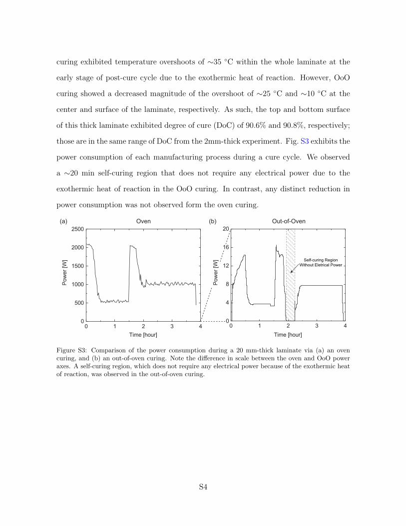
curing exhibited temperature overshoots of ∼35 ◦C within the whole laminate at the
early stage of post-cure cycle due to the exothermic heat of reaction. However, OoO
curing showed a decreased magnitude of the overshoot of ∼25 ◦C and ∼10 ◦C at the
center and surface of the laminate, respectively. As such, the top and bottom surface
of this thick laminate exhibited degree of cure (DoC) of 90.6% and 90.8%, respectively;
those are in the same range of DoC from the 2mm-thick experiment. Fig. S3 exhibits the
power consumption of each manufacturing process during a cure cycle. We observed
a ∼20 min self-curing region that does not require any electrical power due to the
exothermic heat of reaction in the OoO curing. In contrast, any distinct reduction in
power consumption was not observed form the oven curing.
Self-curing RegionWithout Eletrical Power
Oven Out-of-Oven(a) (b)
Figure S3: Comparison of the power consumption during a 20 mm-thick laminate via (a) an ovencuring, and (b) an out-of-oven curing. Note the difference in scale between the oven and OoO poweraxes. A self-curing region, which does not require any electrical power because of the exothermic heatof reaction, was observed in the out-of-oven curing.
S4