Embed Size (px)
DESCRIPTION
spring
Citation preview
INTRODUCTION
In order to conserve natural resources and economize energies, weight reduction has been
the main focus of automobile manufactures as a recent trend. Weight reduction can be achieved by
introducing a better material to the existing one, design optimization and better manufacturing
process. The Suspension leaf spring is one of the potential parts for weight reduction in automobile
as it accounts for 10% to 20% of un-sprung weight, which is considered to be the mass not
supported by the leaf spring.
Advantage of composite leaf spring is it makes the vehicle achieve with more fuel
efficiency and improved riding quality. The introduction of composites materials has made possible
to reduce weight of leaf spring without any reduction of load carrying capacity and stiffness and
also composite materials have more strain energy storage capacity and high strength – to – weight
ratio. So now a day’s composites materials are being used in auto mobile industries to replaced the
metal components or parts.
Composite materials offers oppournity for substantial weight saving. Springs are designed
to absorb and store the energy, then release it hence strain energy of the material an shape become
major factor in designing the spring.
Over a few years plastics based composites materials are being used in automobile to
reduce the weight and conserve the natural resources. However, ecological concern has resulted in
a renewed interest in natural materials for their recyclability, light weight, non-abrasive and non –
polluting properties. Important issues such as recyclability and environmental safety need to be
addresses when the new materials and products are introduced. Lignocelluloses natural fibers such
as flax, hemp, jute and sisal are interesting, environmental friendly alternatives to the use of glass
as reinforcement in engineering composites.
The benefits that these fibers provide over conventional reinforcement materials, and the
development of natural fibers composites has been a subject of interest for past few years.
1.1 Background
Semi elliptical leaf spring is almost universally used for suspension system in light and
heavy commercial vehicles. For cars also, these are widely used for rear suspension.
Springs are placed between the road wheels and the body. When the wheels come across
the bumps on the road body rises and deflects the spring, thereby energy is stored in it or released.
1

Due to the elasticity of the spring material, it rebounds thereby expending the stored
energy. In this way the spring starts vibrating, of course, with amplitude decreasing gradually on
the account of internal friction of the spring material of the suspension joints till vibration cease.
Objective of suspension
To prevent the road shocks from being transmitted to vehicle components.
To safe guard occupants from the road shocks.
To preserve the stability of the vehicle in pitching or rolling while in motion.
1.1.1 Multi leaf spring
Multi leaf springs are widely used for automobile and rail road suspension .It consists of
series of flat plates, usually semi elliptical as shown in fig.
Fig 1.1 Laminated Semi – Elliptical Leaf Spring
The leaves are held together by means of two U-bolts and a center clip .Rebound clips are
provided to keep the leaves in alignment and prevent lateral shifting of the plates during the
operation. The longest leaf called as master leaf is bent at both the ends to form spring eye. At the
center, the spring is fixed to the axle of the car. Multi leaf spring is provided with one or more extra
full length graduated leaves in addition to the master leaf. The extra full length leaves are stacked
between the master leaf and the graduated length leaves. The extra full length is provided to
support the transverse shear force.
2

For the purpose of analysis the leafs are divided in to two groups namely master leaf along
with graduated length leaves forming one group and extra full length leaves forming the other. The
following notations are used in analysis.
nf = number of extra full length leaves
ng = number of graduated length leaves including master leaf
n = total number of leaves
b = width of each leaf (mm)
t = thickness of each leaf (mm)
L = length of cantilever or half the length of semi elliptic spring (mm)
F = force applied at the end of spring (N)
Ff = portion of F taken by extra full length leaves (N)
Fg = portion of F taken by graduated length leaves (N)
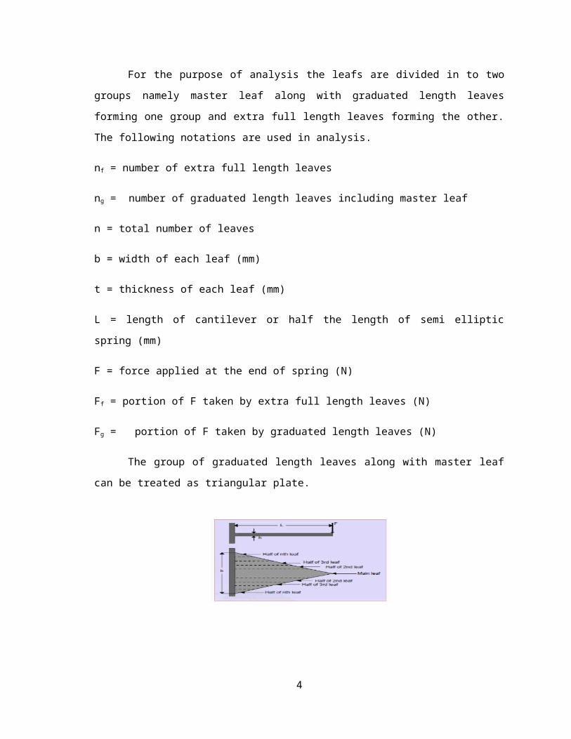
The group of graduated length leaves along with master leaf can be treated as triangular
plate.
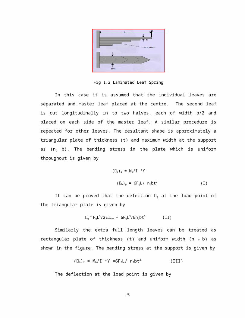
Fig 1.2 Laminated Leaf Spring
3
In this case it is assumed that the individual leaves are separated and master leaf placed at
the centre. The second leaf is cut longitudinally in to two halves, each of width b/2 and placed on
each side of the master leaf. A similar procedure is repeated for other leaves. The resultant shape is
approximately a triangular plate of thickness (t) and maximum width at the support as (n g b). The
bending stress in the plate which is uniform throughout is given by
(b)g = Mb/I *Y
(b)g = 6FgL/ nbbt2 (I)
It can be proved that the defection g at the load point of the triangular plate is given by
g = FgL3/2EImax = 6FgL3/Engbt3 (II)
Similarly the extra full length leaves can be treated as rectangular plate of thickness (t) and
uniform width (n f b) as shown in the figure. The bending stress at the support is given by
(b)f = Mb/I *Y =6FfL/ nfbt2 (III)
The deflection at the load point is given by
f = FfL3/2EImax = 4FfL3/Enfbt3 (IV)
g = f
6FgL3/Engbt3 = 4FfL3/Enfbt3
Fg/Ff = 2ng / 3nf
Also,
Fg + Ff = F
Ff = 3nf F/ (3nf + 2ng)
Ff = 2ng F/ (3nf + 2ng)
(b)f = Mb/I *Y =12 F L/ (3nf + 2ng)bt2
(b)f = Mb/I *Y =18 F L/ (3nf + 2ng)bt2
It is seen from the above equation that the bending stress in full length leaves is more than
those in graduated length leaves. The defection at the end of the spring is given by
4
= 12 F L / (3nf + 2ng) Ebt2
The standard dimensions for the width and thickness of the leaf section m are as follows:
Nominal thickness : 3.2,4.5,6,6.5,7,7.5,8,9,10,11,12,14,and 16
Nominal width( mm) : 32,40,45,,50,55,60,65,70,75,80,90,1000and 125. [9]
1.2 Aim and Objective
A vehicle carries sprung and un-sprung weights during transportation .The un-sprung weighted part
provides a suspension and ride comfort to the drive, this un-sprung weight unnecessarily increases the weight
of the vehicle and it affects the fuel consumption. Some automobile industries are trying to reduce the un-
sprung weight of the vehicle by providing the nearly same ride comfort so that fuel will reduce and it will
help to saving the national wastage.
1.2.1 Problem Identification
The weight of the conventional multi leaf spring is very heavy, i.e. 10 to 20% un-sprung weight of
vehicle.
Due this fuel consumption increases, decreasing the tyre life.
Multi leaf structure creates problems such as producing squeaking sound, fretting corrosion thereby
decreasing the fatigue life.
Sudden spring failure.
High cost
1.2.2 Proposed solution
Composite are the best alternatives to the replace steel leaf spring.
The strength to weight ratio of the composite material is high i.e. 3 to 5 times lighter than the
comparable steel leaf spring.
As single leaf eliminates the problems arising due to multi leaf structure.
Sudden spring failure does not occur due to laminated structure
5
2. LITERATURE SURVEY
Composites materials are now extensively used in the automobile industry instead of metal parts.
Several papers were published on this topic; some of these papers are reviewed here for the further study of
composites materials leaf spring application for automobile.
A single leaf with variable thickness and width for constant cross sectional area of unidirectional
glass fiber reinforced plastic (GFRP) with similar mechanical and geometrical properties to the multi leaf
spring, was designed, fabricated (hand lay- up technique) and tested. The computer algorithm for design for
variable with and variable thickness mono composite leaf spring is explained. Three-dimensional finite
element analysis is used for verification of result obtained from experiment. In which the solid 45 element is
used for steel leaf spring and solid layered 46 element is used for composite leaf spring .For the fabrication of
mono composite leaf spring of E-glass/epoxy hand lay- up technique is used. The experimental test are
carried on both steel and composite leaf spring and compared the result .It is observed that composite leaf
spring is more superior than steel with a large weight reduction [1].
Composite leaf spring is design on basis of fatigue failure .Theoretical equation for prediction
fatigue life is formulated using fatigue modulus and its degrading rate. The dimensions and number of leaves
for both steel leaf spring and composite leaf spring are considered to be same. The stress analysis is
performed using finite element method .The element selected for analysis is solid 45 which behave like a
spring. For the fabrication of each leave the filament winding machine is used and assembled this leaves
together with the help of center bolt and four side clamps. The testing of steel multi leaf spring and
composite multi leaf spring are carried out with the help of an electro-hydraulic leaf spring test rig. Design
and experimental fatigue analysis of composite multi leaf spring are carried out using data analysis. It is
found that composite leaf spring has 67.35%lesser stress, 64.95% higher stiffness and 126.98% higher
natural frequency and also 68.15% weight reduction is achieved [2].
In this paper a four-leaf steel spring used in the rear suspension system of light vehicles is analyzed
using ANSYS V5.4 software. The finite element results showing stresses and deflections verified the existing
analytical and experimental solutions. Using the results of the steel leaf spring, a composite one made from
fiberglass with epoxy resin is designed and optimized using ANSYS. Main consideration is given to the
optimization of the spring geometry. The objective was to obtain a spring with minimum weight that is
capable of carrying given static external forces without failure. The design constraints were stresses (Tsai–
Wu failure criterion) and displacements. The results showed that an optimum spring width decreases
hyperbolically and the thickness increases linearly from the spring eyes towards the axle seat. Compared to
the steel spring, the optimized composite spring has stresses that are much lower, the natural frequency is
higher and the spring weight without eye units is nearly 80% lower [3].
6
This paper presents the design evolution process of a composite leaf spring for freight rail
applications. Three designs of eye-end attachment for composite leaf springs are described. The material
used is glass fiber reinforced polyester. Static testing and finite element analysis have been carried out to
obtain the characteristics of the spring. Load–deflection curves and strain measurement as a function of load
for the three designs tested have been plotted for comparison with FEA predicted values. The main concern
associated with the first design is the delamination failure at the interface of the fibers that have passed
around the eye and the spring body, even though the design can withstand 150 KN static proof load and one
million cycles fatigue load. FEA results confirmed that there is a high inter-laminar shear stress concentration
in that region. The second design feature is an additional transverse bandage around the region prone to
delamination. Delamination was contained but not completely prevented. The third design overcomes the
problem by ending the fibers at the end of the eye section [4].
A single leaf spring with variable thickness of glass fiber reinforced plastic (GFRP) with similar
mechanical and geometrical properties to the multi leaf steel spring was designed, fabricated and tested.
Glass fiber reinforced plastic (GFRP) presents advantages over graphite/epoxy such as lower sensitivity to
cracks, impact and wear damage. The leaf spring model was considered to be a parabolic ally tapered,
constant width beam carrying a concentrated load and assumed to be symmetrical with different cord lengths
for the two limbs of the spring. A finite element program is used to model the behavior of leaf spring. In
addition analytical analysis can be used to develop an expression which is a function of thickness and
position along the spring. In present work the hand lay-up vacuum bag process was initially employed and
mandrels (male and female) were made from plywood according to the desired profile and the glass fiber
fabric was cut to the desired lengths, so that when deposited on the mandrel, would give the calculated
thickness. The operation was simply performed by depositing impregnated glass fiber with epoxy resin over
the rotating mandrel in a hoop pattern. The spring was subjected to a series of laboratory static loading tests.
This study demonstrated that composite can be used for leaf spring for light trucks (jeeps) and meet the
requirement, together with substantial weight saving [5].
In this paper, the influence of ellipticity ratio on performance of woven roving wrapped composite
elliptical springs has been investigated both experimentally and numerically. A series of experiments was
conducted for composite elliptical springs with ellipticity ratios (a/b) ranging from one to two. Mechanical
performance and failure modes of composite elliptic spring elements under static load conditions are
reported. Key design parameters, such as spring rate and failure load, are measured as a function of spring
thickness. Parallel with the experimental work, numerical simulation for fatigue calculations was performed.
The simulation was designed to calculate numerically spring constants of elliptic subjected to the
compressive load along a major axis of the tubes and to calculate the cycle life of the elliptical composite
spring. The simulation was performed using a commercial available finite element package (LUSAS). Eight
noded QTS8 was used since they are expected to give an accurate stress and strain results. Composite elliptic
7

spring with ellipticity ratios of a/b 2.0 displayed the highest spring rate. The present investigation verified
that composites can be utilized for vehicle suspension and meet the requirements, together with substantial
weight saving. It is also believed that hybrid composite elliptical springs have better fatigue behavior than the
conventional and composite leaf and coil spring [6].
In this Paper hand lay-up technique for fabrication of fiber reinforced plastic (FRP) laminated
plates, using glass fibers in the form of continuous roving, is presented. Fabricating the glass fiber roving
reinforced epoxy (GFRRE) laminated plates, three sub-methods have been implemented in the present
investigation: (a) resin flow method, (b) resin transfer method, and (c) impregnation method. Among the
three techniques discussed here, the impregnation method is the most effective, while the resin transfer
method is quite satisfactory. In this study, a new hand lay-up method has been developed by which any plate
having arbitrary number of layers with arbitrary fiber orientation angles, can be fabricated. The impregnation
method has the potential to fabricate FRP laminates, which will compare favorably with most structural
materials and, especially, with other types of FRP laminates as far as the strength-to-weight and modulus-to-
weight ratios are concerned [7].
2.1 Conclusion drawn from literature survey.
The leaf spring is design by considering as it is behave like a cantilever beam. For the analysis
purpose ANSYS software is selected as it gives good result. For the analysis of composite leaf spring the
SOLID46 element is selected and mapped meshing is done. The fabrication of constant width constant
thickness composite leaf spring is done by with the help of hand lay-up method. The specimen is tested
experimentally by conducting a single point bending test. In almost all the paper it is concluded that by using
composite material heavy reduction in the weight is obtain with many other advantages such as reduction in
noise, increasing in comfort ride. The suggestion is that in forthcoming efforts, analysis of FRP leaf spring could
be best possible with Finite Element Method with ANSYS. The work is to design the FRP leaf spring, for
fabrication of FRP leaf spring the hand lay -up technique is used as it is more economical than the other method of
fabrication. A stress analysis is performed using finite element method (FEM) and ANSYS Software. Considering
the environmental issues the use of natural fibers in composite can also be recommended. The natural fibers such
as Jute, Flax , Hemp, Sisal Coir etc can also be used The experimental test has to be carried on both Glass Fiber
Reinforced Composite (GFRC) and Natural Fiber Reinforced Composite (NFRC) leaf spring and compared the
result. Fatigue analysis is required to find the life of GFRC leaf spring.
8
+ =
3. SELECTION OF MATERIAL
3.1 Composite material
A combination of two or more materials to form a new material with improved mechanical
properties like strength, stiffness, young’s modulus etc.
Material constitute nearly 60 to 70% of vehicle weight and its related cost
The strain energy of the material becomes a major factor in the designing the spring .The
relationship of the specific strain energy can be formulated as,
Where,
U=Strain Energy
σ= Stress
ρ= Density of Material
E=Young s Modulus of the Material
The stored elastic strain energy in a leaf spring varies directly proportional with the square of
maximum allowable stress and inversely proportional with the modulus of elasticity both in the longitudinal
and transverse direction.
The composite material have more elastic strain energy storage capacity and high strength – to –
weight ratio as compared to those of steel thus composite materials have been selected for leaf spring.
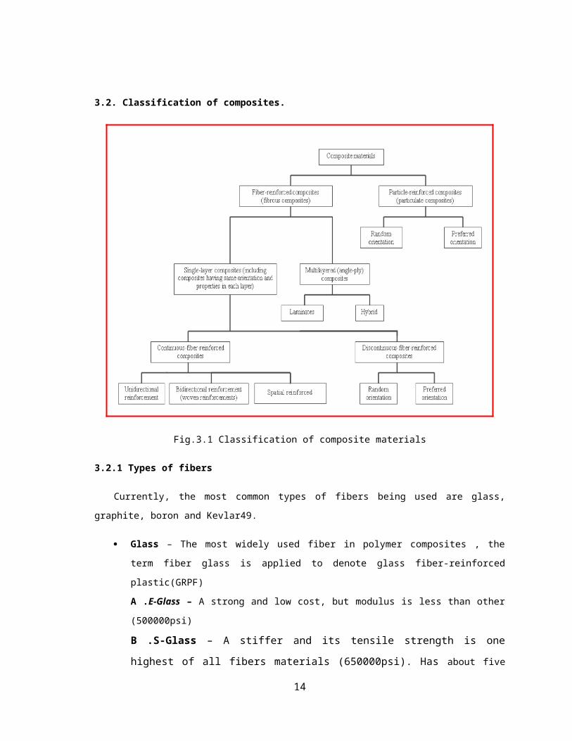
3.2. Classification of composites.
9
Reinforcement Matrix Composites
Fig.3.1 Classification of composite materials
3.2.1 Types of fibers
Currently, the most common types of fibers being used are glass, graphite, boron and Kevlar49.
Glass – The most widely used fiber in polymer composites , the term fiber glass is applied to
denote glass fiber-reinforced plastic(GRPF)
A .E-Glass – A strong and low cost, but modulus is less than other (500000psi)
B .S-Glass – A stiffer and its tensile strength is one highest of all fibers materials
(650000psi). Has about five times the tensile strength of steel and has density of about one third
that of the steel.
Graphite (carbon) - They are generally a combination of different form of graphite. Graphite has
tensile strength three to five times stronger than steel and has density that is one fourth of steel.
Boron – It is having very high elastic modulus, but its high cost limits its application to aerospace
components.
Ceramics – Silicon carbide (SiC) and aluminum oxide (Al2O3) are the main fiber materials among
ceramics. Both have high elastic moduli and can be used to strengthen low- density, low modulus
metals such as aluminum and magnesium.
10
Metal- Steel filaments used as reinforcing fiber in plastics.
Graph 3.1 Stress-Strain Curve of Composites
Sr. no. Types of fiber Properties
1 E- Glass High Stiffness ,high buckling ,weak in shear, low cost
2 S-Glass High Stiffness ,high buckling ,weak in shear, high cost
3 Carbon fiber
High strength, h
igh modulus, low density, high temperature resistance, considerably high
cost.
4 Ceramic High temperature resistant, low thermal conductivity.
Table 3.1 Properties of fibers
3.2.2 Fiber Reinforced Polymer Composite or Fiber Reinforced Composite
Fibers the important class of reinforcement , as they satisfy the desired conditions and transfer
strength to the matrix .Glass fibers are the earliest known fibers used in reinforcement .Ceramics and metals
fibers were introduced later and are put extensively into use, to render composite stiffer and more resistant
to heat . Fibers fall short of ideal performance due to several factors. The performance of a composite is
judged by its length, shape, orientation and composition of the fibers and the mechanical properties of the
matrix.
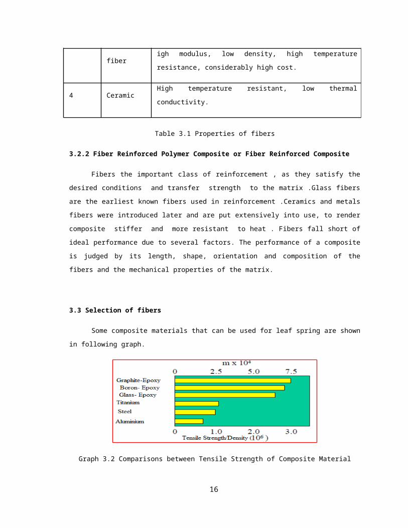
3.3 Selection of fibers
Some composite materials that can be used for leaf spring are shown in following graph.
11
Graph 3.2 Comparisons between Tensile Strength of Composite Material
From the graph, it is clear that for spring application, graphite & boron composite demonstrate the
best results displaying superior properties over other composites. Due to limitations of unavailability and
cost these fibers are not being used in the present work. The forms of carbon fiber, which is capable of
storing the greatest amount of energy. These materials have high strength, stiffness and low weight. But on
the other hand, they have low impact strength. When carbon is added to other metals, there would be
corrosion in components. These fibers are also costly compared with other fibers making them limited for
commercial practical use. The advantage of glass fiber over graphite or carbon is its lower sensitivity to
cracks & wear damage, also has better corrosion resistance , higher impact and low cost. A good
combination of material properties and the cost is obtained with the glass fibers.
Thus we can use the glass fiber for fabrication of springs. The specific strain energy of the steel
spring and some composites are compared in fig .when the ultimate static strength is used for σ.
The S2 –Glass –Epoxy value is set to 1 and the other values are expressed as their relative
percentages to it regarding the dynamic nature of loading on spring , the hatched region identify the quantity
of specific strain energy in dynamic loading when the fatigue strength is used for σ. Glass fibers consist of
two major types E and S2.
Graph 3.3 Specific Strain Energies of the spring materials
12
Although S2 fibers have better mechanical properties than E - fibers, but the cost associated with E-
Glass is much lower to that of S2 .So in present work the E-Glass/Epoxy is selected as the material for
manufacturing of spring.
3.3.1 Glass fiber
Glass is the most common fiber used in polymer matrix composites. Its advantages include its
strength, low cost, highly chemical resistant. The main types are E-Glass and S-Glass.The alphabet E-stands
for electrical, as it was designed for electrical applications. However, it is being used for many other
purposes now, such as decoration and structural applications. The alphabet S – stands for high content of
silica, it retains its strength and elevated temperatures and also has higher fatigue strength.
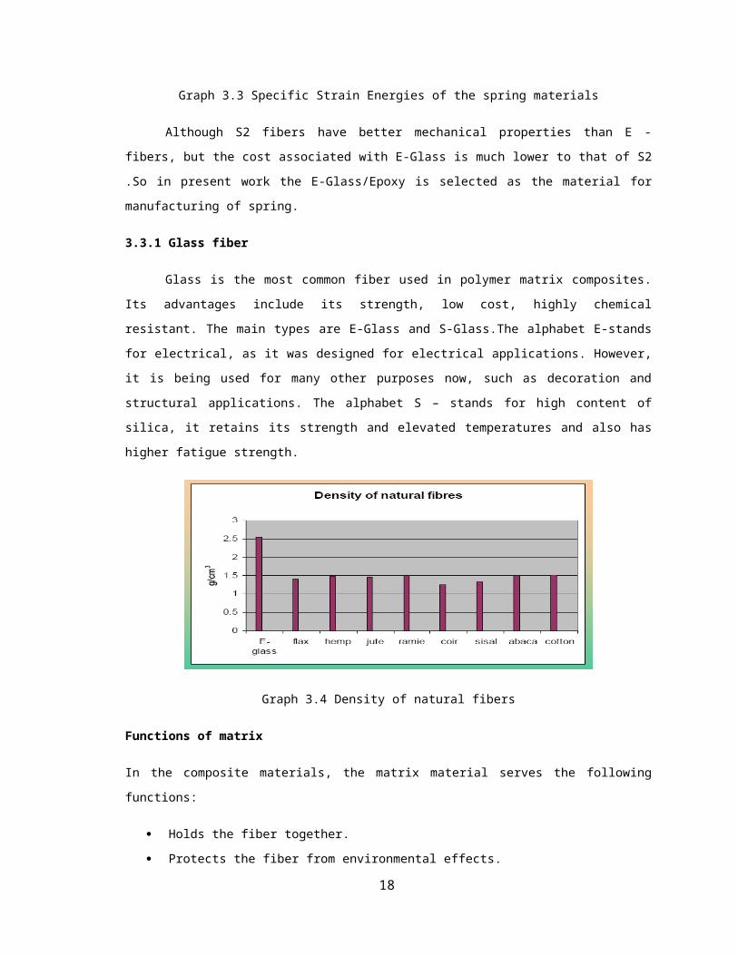
Graph 3.4 Density of natural fibers
Functions of matrix
In the composite materials, the matrix material serves the following functions:
Holds the fiber together.
Protects the fiber from environmental effects.
Distributes the load evenly between fibers so that all fibers are subjected to same amount of strain.
Enhances the transverse properties of a laminate
Improves impact and fracture resistance of the component.
Helps to avoid crack propagation and crack growth through the fibers by providing alternate failure
path along the interface between the fibers and matrix.
3.4 Characteristics of the fibers reinforced polymers composites
Many factors must be considered while designing a fiber – reinforced composite, including length,
diameter, orientation, amount and properties of the fiber, the properties of matrix and the bonding between
the fibers and matrix.
13
3.4.1 Fiber length and diameter.
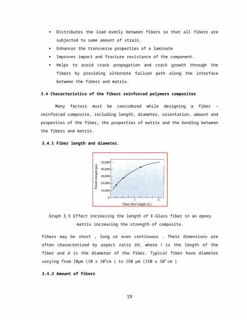
Graph 3.5 Effect increasing the length of E-Glass fiber in an epoxy matrix increasing the strength of
composite.
Fibers may be short , long or even continuous . Their dimensions are often characterized by aspect ratio l/d,
where l is the length of the fiber and d is the diameter of the fiber. Typical fiber have diameter varying from
10µm (10 x 104cm ) to 150 µm (150 x 104 cm )
3.4.2 Amount of fibers
A great volume fraction of fiber increases the strength and stiffness of the composite, as we would
expect from the rule of matrix. However, the maximum volume fraction is about 80%, beyond which the
fiber can no longer be surrounded by the matrix.
3.4.3 Orientation of fiber
14

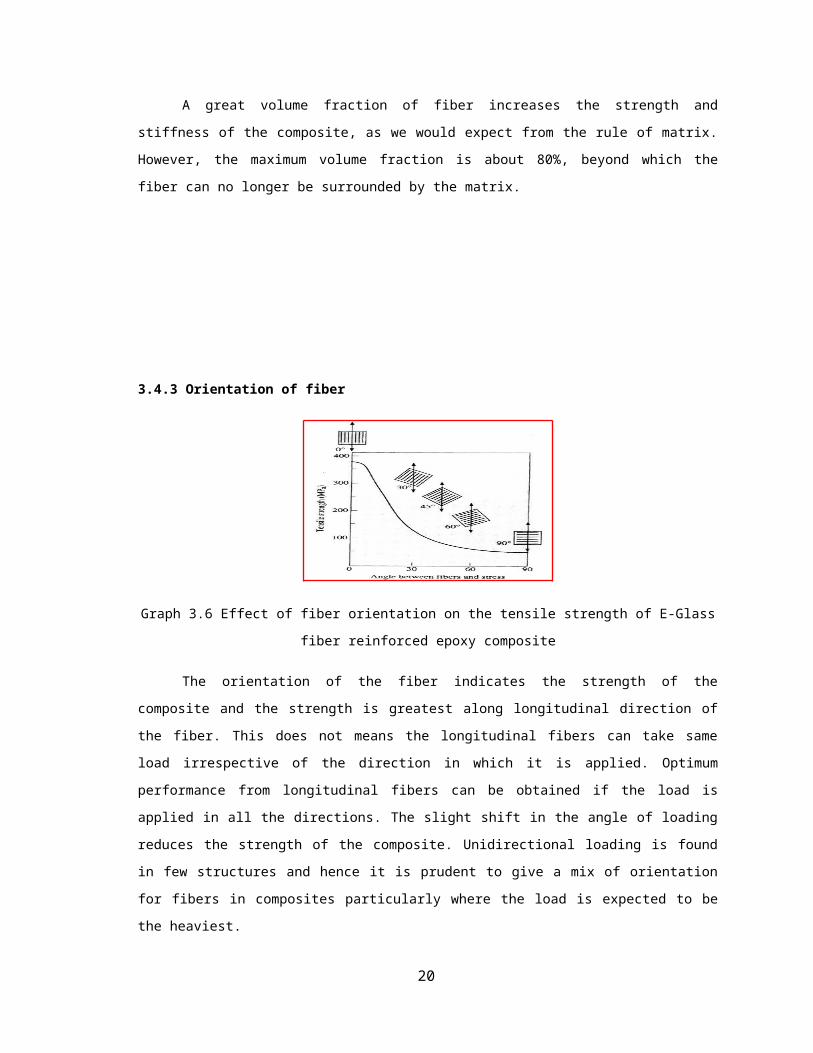
Graph 3.6 Effect of fiber orientation on the tensile strength of E-Glass fiber reinforced epoxy composite
The orientation of the fiber indicates the strength of the composite and the strength is greatest along
longitudinal direction of the fiber. This does not means the longitudinal fibers can take same load
irrespective of the direction in which it is applied. Optimum performance from longitudinal fibers can be
obtained if the load is applied in all the directions. The slight shift in the angle of loading reduces the
strength of the composite. Unidirectional loading is found in few structures and hence it is prudent to give a
mix of orientation for fibers in composites particularly where the load is expected to be the heaviest.
3.4.4 Fiber properties
In most fiber reinforced composite, the fiber is strong, stiff and light weight. If the composite is to
be used at elevated temperatures, the fiber should have high melting temperature. Thus specific strength and
specific modulus of the fibers are important characteristic.
Specific strength= TS/ρ
Specific modulus = E/ρ
Where, TS= tensile strength
ρ = the density of material
E = Modulus of elasticity
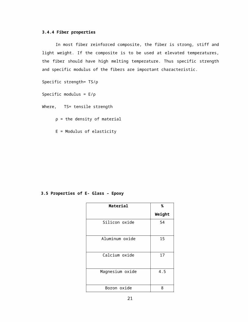
3.5 Properties of E- Glass – Epoxy
Material % Weight
Silicon oxide 54
Aluminum oxide 15
Calcium oxide 17
15
Magnesium oxide 4.5
Boron oxide 8
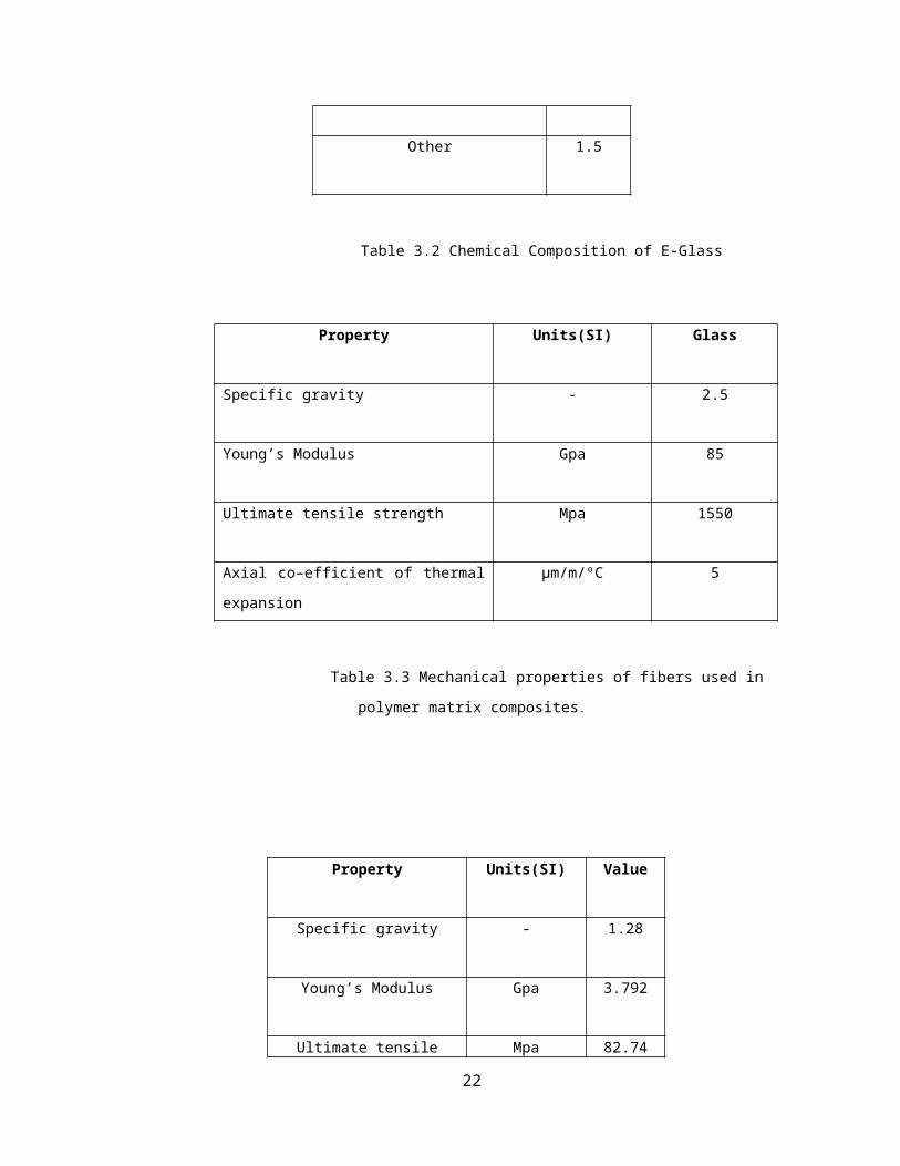
Other 1.5
Table 3.2 Chemical Composition of E-Glass
Property Units(SI) Glass
Specific gravity - 2.5
Young’s Modulus Gpa 85
Ultimate tensile strength Mpa 1550
Axial co–efficient of thermal expansion µm/m/ºC 5
Table 3.3 Mechanical properties of fibers used in polymer matrix composites.
Property Units(SI) Value
Specific gravity - 1.28
Young’s Modulus Gpa 3.792
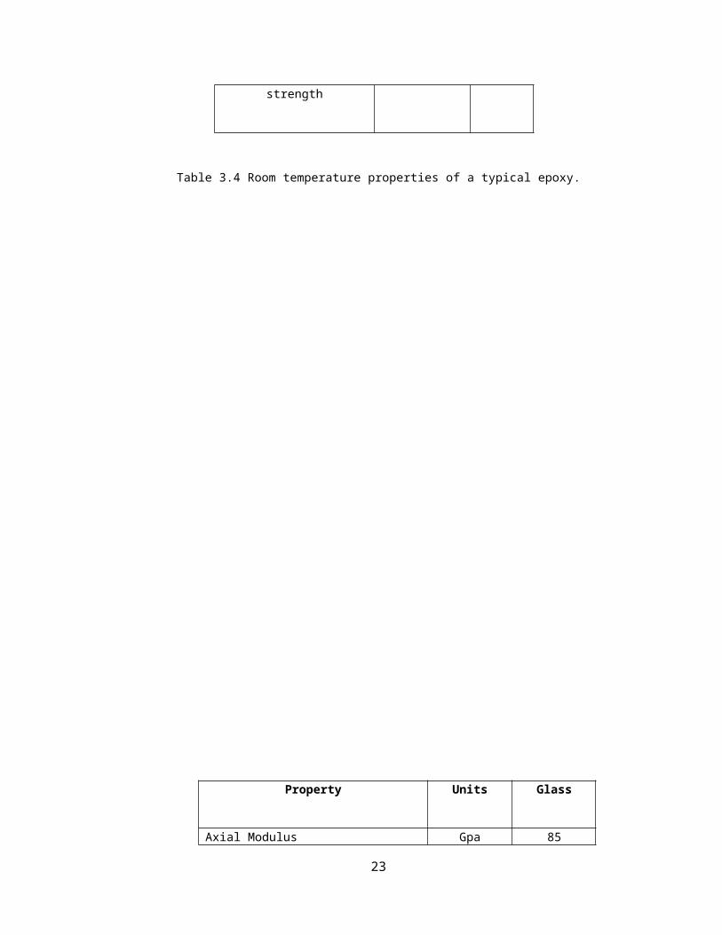
Ultimate tensile strength Mpa 82.74
16

Table 3.4 Room temperature properties of a typical epoxy.
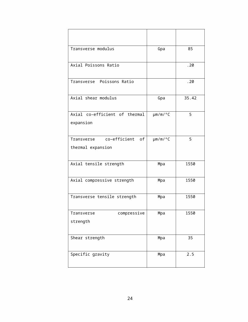
Property Units Glass
Axial Modulus Gpa 85
Transverse modulus Gpa 85
Axial Poissons Ratio .20
Transverse Poissons Ratio .20
17
Axial shear modulus Gpa 35.42
Axial co–efficient of thermal expansion µm/m/ºC 5
Transverse co–efficient of thermal
expansion
µm/m/ºC 5
Axial tensile strength Mpa 1550
Axial compressive strength Mpa 1550
Transverse tensile strength Mpa 1550
Transverse compressive strength Mpa 1550
Shear strength Mpa 35
Specific gravity Mpa 2.5
Table 3.5 Typical properties of glass fiber (SI System of Units)
Glass –Epoxy lamina consists of 70% fiber volume fraction .Use properties of glass and epoxy from
the table 3.4 and table 3.5, respectively, to determine volume and mass of matrix
ρm = 1200 kg /m3
Property Units Glass
Axial Modulus Gpa 3.4
Transverse modulus Gpa 3.4
Axial Poissons Ratio ----- .30
Transverse Poissons Ratio ----- .30
18
Axial shear modulus Gpa 1.308
Co–efficient of thermal expansion µm/m/ºC 63
Co–efficient of moisture expansion µm/m/kg/kg .33
Axial tensile strength Mpa 72
Axial compressive strength Mpa 102
Transverse tensile strength Mpa 72
Transverse compressive strength Mpa 102
Shear strength Mpa 34
Specific gravity Mpa 1.2
Table 3.6 Typical properties of matrices (SI System of Units)
Using the definition of fiber and matrix
1. Density of the lamina
2. Mass fraction of the glass and epoxy
3. Volume of the composite lamina if the mass of the lamina is assumed 4 kg
4. Volume and mass of glass and epoxy in part.
From the table 3.5, the density volume fractions is calculated as,
ρ c = ρ f V f + ρ m V m
Using the above equation the density of the composite is
ρc = (2500) (0.7)+ (1200) (0.3)
ρc = 2110 kg/m3
19
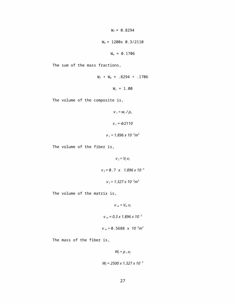
Fiber and mass fraction is calculated as,
Wf = 2500x0.7/2110
Wf = 0.8294
Wm = 1200x 0.3/2110
Wm = 0.1706
The sum of the mass fractions,
Wf + Wm = .8294 + .1706
Wc = 1.00
The volume of the composite is,
v c = wc / ρc
v c = 4/2110
v c = 1.896 x 10 -3m3
The volume of the fiber is,
v f = Vf vc
v f = 0.7 x 1.896 x 10 -3
v f = 1.327 x 10 -3m3
The volume of the matrix is,
v m = Vm vc
v m = 0.3 x 1.896 x 10 -3
v m = 0.5688 x 10 -3m3
The mass of the fiber is,
Wf = ρ c vf
Wf = 2500 x 1.327 x 10 -3
Wf = 3.318 kg
20
The mass of the matrix is,
Wm = ρ m vm
Wm = 1200 x 0.5688 x 10 -3
Wm = 0.6826 kg
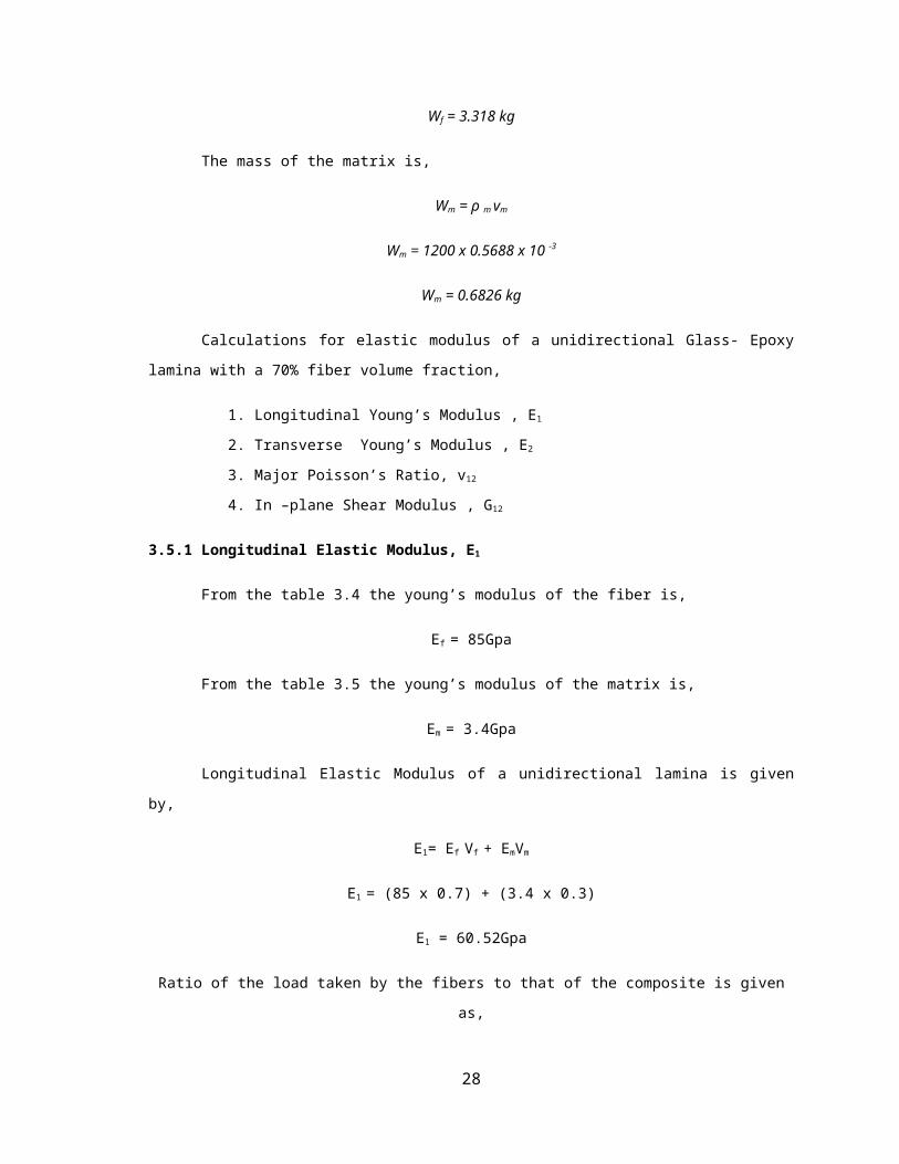
Calculations for elastic modulus of a unidirectional Glass- Epoxy lamina with a 70% fiber volume
fraction,
1. Longitudinal Young’s Modulus , E1
2. Transverse Young’s Modulus , E2
3. Major Poisson’s Ratio, v12
4. In –plane Shear Modulus , G12
3.5.1 Longitudinal Elastic Modulus, E1
From the table 3.4 the young’s modulus of the fiber is,
Ef = 85Gpa
From the table 3.5 the young’s modulus of the matrix is,
Em = 3.4Gpa
Longitudinal Elastic Modulus of a unidirectional lamina is given by,
E1= Ef Vf + EmVm
E1 = (85 x 0.7) + (3.4 x 0.3)
E1 = 60.52Gpa
Ratio of the load taken by the fibers to that of the composite is given as,
Ff/Fc = (Ef/E1) x Vf
Ff/Fc = (85/60.52) x 0.7
Ff/Fc = 0.9831
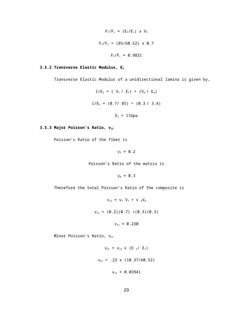
3.5.2 Transverse Elastic Modulus, E2
Transverse Elastic Modulus of a unidirectional lamina is given by,
21
1/E2 = ( Vf / Ef) + (Vm / Em)
1/E2 = (0.7/ 85) + (0.3 / 3.4)
E2 = 11Gpa
3.5.3 Major Poisson’s Ratio, v12
Poisson’s Ratio of the fiber is
vf = 0.2
Poisson’s Ratio of the matrix is
vm = 0.3
Therefore the total Poisson’s Ratio of the composite is
v12 = vf Vf + v mVm
v12 = (0.2)(0.7) +(0.3)(0.3)
v12 = 0.230
Minor Poisson’s Ratio, v21
v21 = v12 x (E 2/ E1)
v21 = .23 x (10.37/60.52)
v21 = 0.03941
3.5.4 In – Plane Shear Modulus, G12
Shear Modulus of the Fiber,
Gf = Ef/2(1+ vf) = 85/2(1+0.2)
Gf = 35.42Gpa
Shear Modulus of the Matrix is,
Gm = Em/2(1+ vm) = 3.4/2(1+0.3)
Gm = 1.308Gpa
22
In – plane shear modulus of the unidirectional lamina is
1/G12 = ( Vf / Gf) + (Vm / Gm)
1/G12 = (0.7 / 35.42) + (0.3 / 1.308)
G12 = 4.014Gpa
Property Units E-Glass/Epoxy
E1 Gpa 60.52
E2 Gpa 11
v12 --- 0.230
v21 --- .03941
G12 Gpa 4.014
Table 3.7 Properties of E-Glass Epoxy
3.6 Natural fibers selection:
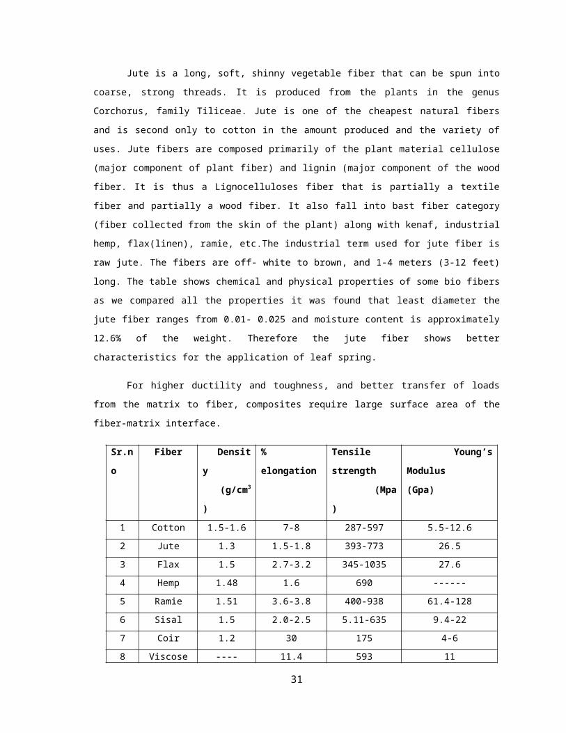
Jute is a long, soft, shinny vegetable fiber that can be spun into coarse, strong threads. It is produced
from the plants in the genus Corchorus, family Tiliceae. Jute is one of the cheapest natural fibers and is
second only to cotton in the amount produced and the variety of uses. Jute fibers are composed primarily of
the plant material cellulose (major component of plant fiber) and lignin (major component of the wood fiber.
It is thus a Lignocelluloses fiber that is partially a textile fiber and partially a wood fiber. It also fall into bast
fiber category (fiber collected from the skin of the plant) along with kenaf, industrial hemp, flax(linen),
ramie, etc.The industrial term used for jute fiber is raw jute. The fibers are off- white to brown, and 1-4
meters (3-12 feet) long. The table shows chemical and physical properties of some bio fibers as we compared
all the properties it was found that least diameter the jute fiber ranges from 0.01- 0.025 and moisture content
is approximately 12.6% of the weight. Therefore the jute fiber shows better characteristics for the
application of leaf spring.
For higher ductility and toughness, and better transfer of loads from the matrix to fiber, composites
require large surface area of the fiber-matrix interface.
Sr.no Fiber Density
(g/cm3 )
% elongation Tensile strength
(Mpa)
Young’s Modulus
(Gpa)
1 Cotton 1.5-1.6 7-8 287-597 5.5-12.6
2 Jute 1.3 1.5-1.8 393-773 26.5
23
3 Flax 1.5 2.7-3.2 345-1035 27.6
4 Hemp 1.48 1.6 690 ------
5 Ramie 1.51 3.6-3.8 400-938 61.4-128
6 Sisal 1.5 2.0-2.5 5.11-635 9.4-22
7 Coir 1.2 30 175 4-6
8 Viscose ---- 11.4 593 11
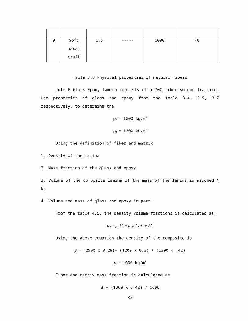
9 Soft wood
craft
1.5 ----- 1000 40
Table 3.8 Physical properties of natural fibers
Jute E-Glass-Epoxy lamina consists of a 70% fiber volume fraction. Use properties of glass and
epoxy from the table 3.4, 3.5, 3.7 respectively, to determine the
ρm = 1200 kg/m3
ρf = 1300 kg/m3
Using the definition of fiber and matrix
1. Density of the lamina
2. Mass fraction of the glass and epoxy
3. Volume of the composite lamina if the mass of the lamina is assumed 4 kg
4. Volume and mass of glass and epoxy in part.
From the table 4.5, the density volume fractions is calculated as,
ρ c = ρ f V f + ρ m V m + ρ j V j
Using the above equation the density of the composite is
ρc = (2500 x 0.28)+ (1200 x 0.3) + (1300 x .42)
ρc = 1606 kg/m3
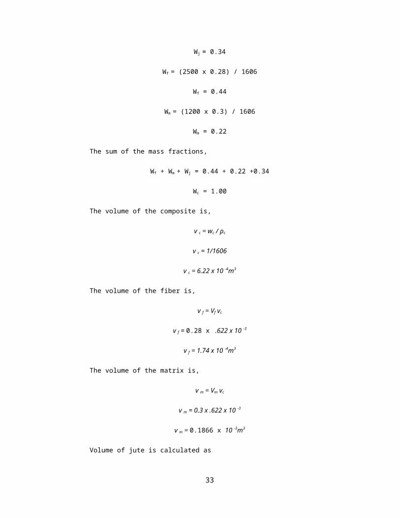
Fiber and matrix mass fraction is calculated as,
Wj = (1300 x 0.42) / 1606
Wj = 0.34
24

Wf = (2500 x 0.28) / 1606
Wf = 0.44
Wm = (1200 x 0.3) / 1606
Wm = 0.22
The sum of the mass fractions,
Wf + Wm + Wj = 0.44 + 0.22 +0.34
Wc = 1.00
The volume of the composite is,
v c = wc / ρc
v c = 1/1606
v c = 6.22 x 10 -4m3
The volume of the fiber is,
v f = Vf vc
v f = 0.28 x .622 x 10 -3
v f = 1.74 x 10 -4m3
The volume of the matrix is,
v m = Vm vc
v m = 0.3 x .622 x 10 -3
v m = 0.1866 x 10 -3m3
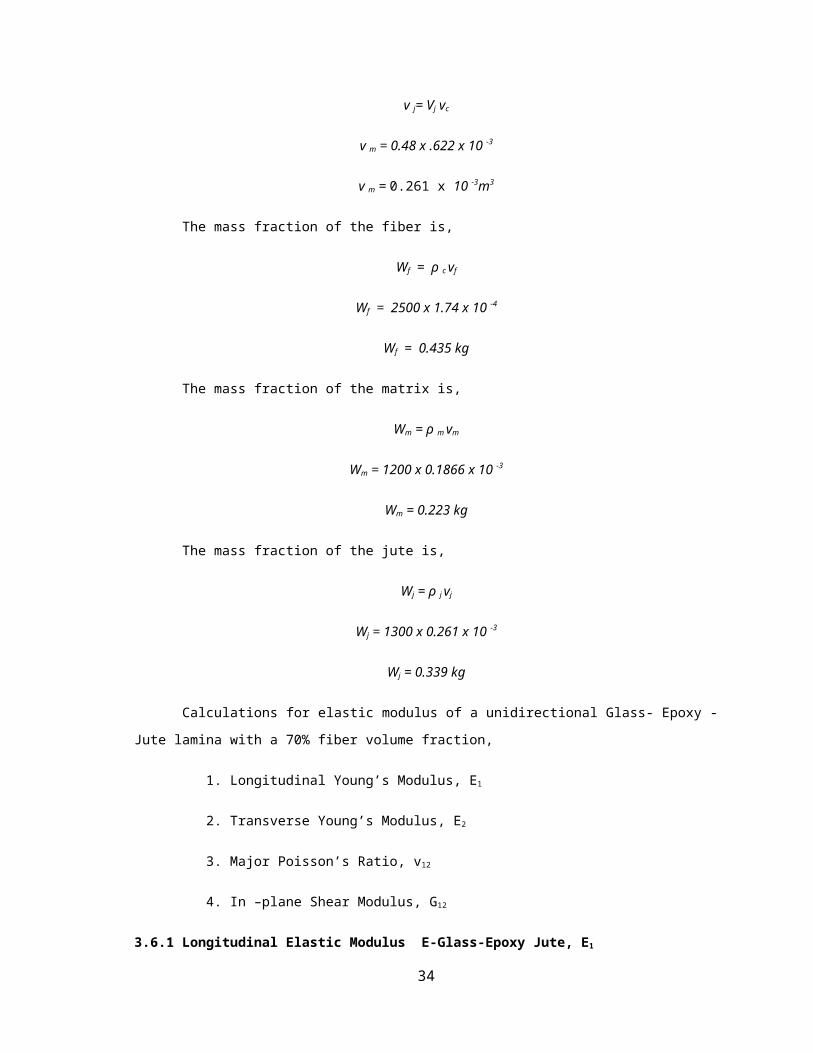
Volume of jute is calculated as
v j= Vj vc
v m = 0.48 x .622 x 10 -3
v m = 0.261 x 10 -3m3
The mass fraction of the fiber is,
25

Wf = ρ c vf
Wf = 2500 x 1.74 x 10 -4
Wf = 0.435 kg
The mass fraction of the matrix is,
Wm = ρ m vm
Wm = 1200 x 0.1866 x 10 -3
Wm = 0.223 kg
The mass fraction of the jute is,
Wj = ρ j vj
Wj = 1300 x 0.261 x 10 -3
Wj = 0.339 kg
Calculations for elastic modulus of a unidirectional Glass- Epoxy - Jute lamina with a 70% fiber
volume fraction,
1. Longitudinal Young’s Modulus, E1
2. Transverse Young’s Modulus, E2
3. Major Poisson’s Ratio, v12
4. In –plane Shear Modulus, G12
3.6.1 Longitudinal Elastic Modulus E-Glass-Epoxy Jute, E1
From the table 3.4 the young’s modulus of the fiber is,
Ef = 85Gpa
From the table 3.5 the young’s modulus of the matrix is,
Em = 3.4Gpa
Longitudinal Elastic Modulus of a unidirectional lamina is given by,
E1= Ef Vf + EmVm + Ej Vj
26
E1 = (85 x 0.28) + (3.4 x 0.3) + (26.5 x 0.48)
E1 = 37.54 Gpa
3.6.2 Transverse Elastic Modulus E-Glass-Epoxy Jute,E2
Transverse Elastic Modulus of a unidirectional lamina is given by,
1/E2 = ( Vf / Ef) + (Vm / Em) + (Vj / Ej)
1/E2 = (0.28/ 85) + (0.3 / 3.4) + (.48/26.5)
E2 = 9.12Gpa
3.6.3 Major Poisson’s Ratio E-Glass-Epoxy Jute, v12
Poisson’s Ratio of the E-Glass fiber is
vf = 0.2
Poisson’s Ratio of the jute fiber is
vj = 0.38
Poisson’s Ratio of the matrix is
vm = 0.3
Therefore the total Poisson’s Ratio of the composite is
v12 = vf Vf + v mVm + vj Vj
v12 = (0.38 x 0.48) + (0.2 x 0.28) + (0.3 x 0.3)s
v12 = 0.3284
Minor Poisson’s Ratio, v21
v21 = v12 x ( E 2/ E1)
v21 = 0.3284 x (9.12 /37.54)
v21 = 0.0798
3.6.4 In – Plane Shear Modulus E-Glass-Epoxy Jute ,G12
27
Shear Modulus of the Fiber,
Gf = Ef/2(1+ vf) = 85/2(1+0.28)
Gf = 33.2Gpa
Shear Modulus of the Jute Fiber,
Gj = Ej/2(1+ vj) = 26.5/2(1+0.42)
Gf = 9.33Gpa
Shear Modulus of the Matrix is,
Gm = Em/2(1+ vm) = 3.4/2(1+0.3)
Gm = 1.308Gpa
In – plane shear modulus of the unidirectional lamina is
1/G12 = ( Vf / Gf) + (Vm / Gm) +(Vj / Gj)
1/G12 = (0.28 / 33.2) + (0.3 / 1.308) + (0.48 / 9.33)
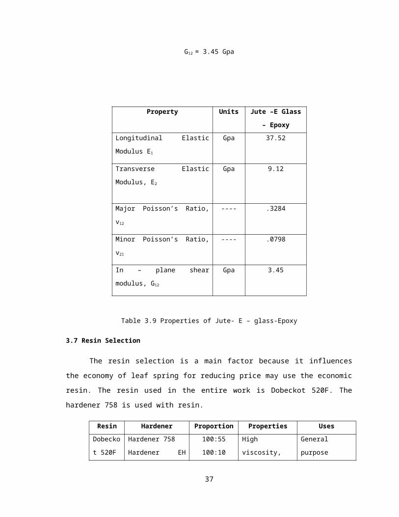
G12 = 3.45 Gpa
Property Units Jute –E Glass –
Epoxy
Longitudinal Elastic Modulus E1 Gpa 37.52
Transverse Elastic Modulus, E2 Gpa 9.12
Major Poisson’s Ratio, v12 ---- .3284
Minor Poisson’s Ratio, v21 ---- .0798
In – plane shear modulus, G12 Gpa 3.45
Table 3.9 Properties of Jute- E – glass-Epoxy
3.7 Resin Selection
28
The resin selection is a main factor because it influences the economy of leaf spring for
reducing price may use the economic resin. The resin used in the entire work is Dobeckot 520F.
The hardener 758 is used with resin.
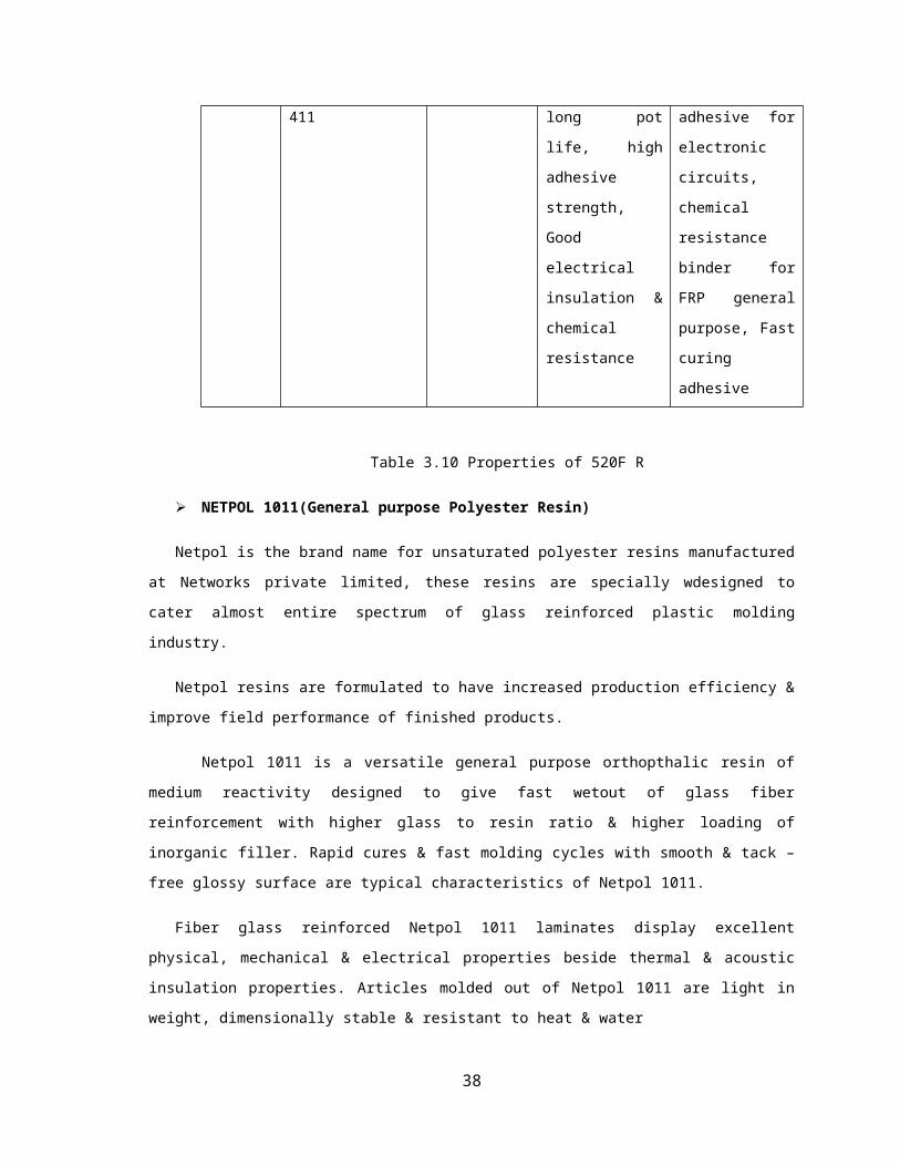
Resin Hardener Proportion Properties Uses
Dobeckot
520F
Hardener 758
Hardener EH 411
100:55
100:10
High viscosity,
long pot life, high
adhesive strength,
Good electrical
insulation &
chemical resistance
General purpose
adhesive for
electronic circuits,
chemical resistance
binder for FRP
general purpose,
Fast curing
adhesive
Table 3.10 Properties of 520F R
NETPOL 1011(General purpose Polyester Resin)
Netpol is the brand name for unsaturated polyester resins manufactured at Networks private limited,
these resins are specially wdesigned to cater almost entire spectrum of glass reinforced plastic molding
industry.
Netpol resins are formulated to have increased production efficiency & improve field performance of
finished products.
Netpol 1011 is a versatile general purpose orthopthalic resin of medium reactivity designed to give
fast wetout of glass fiber reinforcement with higher glass to resin ratio & higher loading of inorganic filler.
Rapid cures & fast molding cycles with smooth & tack – free glossy surface are typical characteristics of
Netpol 1011.
Fiber glass reinforced Netpol 1011 laminates display excellent physical, mechanical & electrical
properties beside thermal & acoustic insulation properties. Articles molded out of Netpol 1011 are light in
weight, dimensionally stable & resistant to heat & water
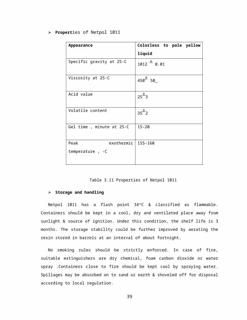
Properties of Netpol 1011
Appearance Colorless to pale yellow liquid
29

Specific gravity at 25◦C1012 0.01
Viscosity at 25◦C450 50
Acid value 25 3
Volatile content 35 2
Gel time , minute at 25◦C 15-20
Peak exothermic temperature , ◦C 155-160
Table 3.11 Properties of Netpol 1011
Storage and handling
Netpol 1011 has a flash point 34ºC & classified as flammable. Containers should be kept in a cool, dry
and ventilated place away from sunlight & source of ignition. Under this condition, the shelf life is 3 months.
The storage stability could be further improved by aerating the resin stored in barrels at an interval of about
fortnight.
No smoking rules should be strictly enforced. In case of fire, suitable extinguishers are dry chemical,
foam carbon dioxide or water spray .Containers close to fire should be kept cool by spraying water. Spillages
may be absorbed on to sand or earth & shoveled off for disposal according to local regulation.
Caution
Store accelerator and catalyst separately. Do not allow them to come in contact with each other as they
form violently explosive mixture. It is recommended that the accelerator be blended in to resin first and then
catalyst be added immediately before use.
Physiological and toxological behavior of Netpol 1011
The molding are should be sufficiently ventilated for reducing the styrene vapor levels in the air
while molding.Skin contact and vapor inhalation must be avoided during molding because of the presence of
styrene monomers. In case of irritation in the eye or skin, it is recommended to wash with copious amount of
water. In extreme case, seek immediate medical advice.
30
Uses
Netpol 1011 is suitable for variety of contact molding FRP articles such as,
Furniture
Building panels
Automotive hoods
Modular housings
Boats
Sanitary wear
Machine covers & guards
Cooling towers
4. DESIGN OF LEAF SPRING
Multi – leaf spring consist of series of flat plates which are held together with the help of U – bolt
and center clip longest leaf known as master leaf and the other leafs known as graduated leaves. The spring is
designed by considering the group of leaves as triangular plate as shown in figure and the design procedure is
as follows.
4.1 Design of Leaf Spring
Parameters Value
Material selected – Steel 55Si2Mn90
Tensile strength (N/mm2) 1962
Yield strength (N/mm2) 1470
Young’s modulus E (N/mm2) 2.1x10⁵
Design Stress (σb) (N/mm2) 653
31
Total length (mm) 1010
The arc length between the axle seat and the front
eye(mm)580
Arc height at the axle seat (mm) 120
Spring rate (N/mm) 31.98
Normal static loading (N) 2943
Available space for spring width (mm) 45
Spring weight (Kg) 13.4
Table 4.1 Parameters of steel leaf spring
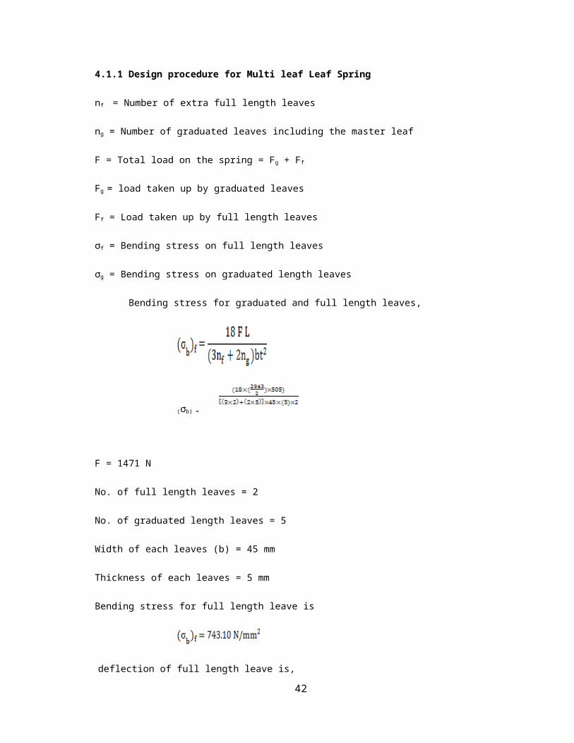
4.1.1 Design procedure for Multi leaf Leaf Spring
nf = Number of extra full length leaves
ng = Number of graduated leaves including the master leaf
F = Total load on the spring = Fg + Ff
Fg = load taken up by graduated leaves
Ff = Load taken up by full length leaves
σf = Bending stress on full length leaves
σg = Bending stress on graduated length leaves
Bending stress for graduated and full length leaves,
(σb) =
F = 1471 N
No. of full length leaves = 2
No. of graduated length leaves = 5
32
Width of each leaves (b) = 45 mm
Thickness of each leaves = 5 mm
Bending stress for full length leave is
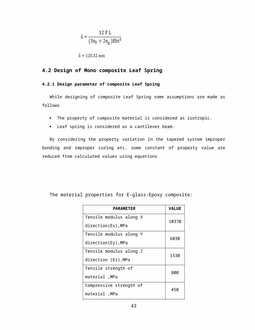
deflection of full length leave is,
4.2 Design of Mono composite Leaf Spring
4.2.1 Design parameter of composite Leaf Spring
While designing of composite Leaf Spring some assumptions are made as follows
The property of composite material is considered as isotropic.
Leaf spring is considered as a cantilever beam.
By considering the property variation in the tapered system improper bonding and improper curing etc.
some constant of property value are reduced from calculated values using equations
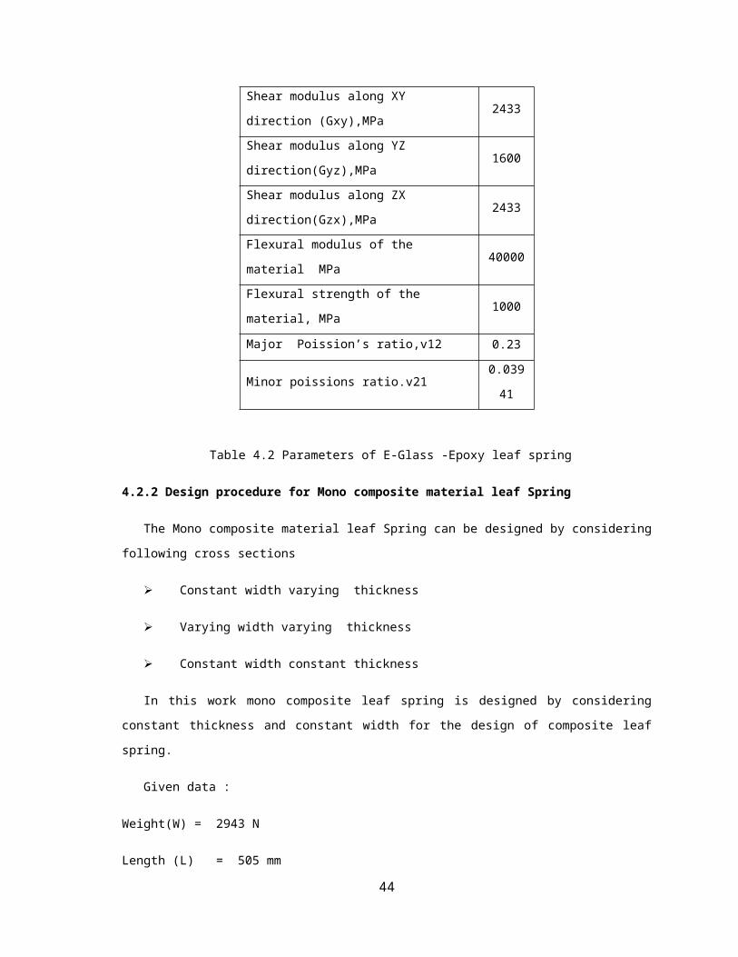
The material properties for E-glass-Epoxy composite:
PARAMETER VALUE
Tensile modulus along X direction(Ex),MPa 10370
Tensile modulus along Y direction(Ey),MPa 6030
Tensile modulus along Z direction (Ez),MPa 1530
Tensile strength of material ,MPa 800
Compressive strength of material ,MPa 450
Shear modulus along XY direction 2433
33
(Gxy),MPa
Shear modulus along YZ direction(Gyz),MPa 1600
Shear modulus along ZX direction(Gzx),MPa 2433
Flexural modulus of the material MPa 40000
Flexural strength of the material, MPa 1000
Major Poission’s ratio,v12 0.23
Minor poissions ratio.v21 0.03941
Table 4.2 Parameters of E-Glass -Epoxy leaf spring
4.2.2 Design procedure for Mono composite material leaf Spring
The Mono composite material leaf Spring can be designed by considering following cross sections
Constant width varying thickness
Varying width varying thickness
Constant width constant thickness
In this work mono composite leaf spring is designed by considering constant thickness and constant
width for the design of composite leaf spring.
Given data :
Weight(W) = 2943 N
Length (L) = 505 mm
δ max = 120mm
σ max = 2000 N/mm2
Factor of Safety = 2.5
E = 10.37 GPa
K.required = 25N/mm
34

1) Let, b =45 mm, t = 20 mm
step 1: σa =
=
= 800 N/mm2
Thus the value for b,t satisfied 1st condition.
step 2: σ =
=
= 495.505 N/mm2
σa σ
Step 3:
=
= 30000
35

δ =
= = 382.8 mm
Thus values for b,t fails it does not satisfied 2nd condition.
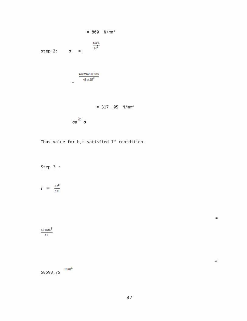
2) Let, b = 25 mm, t =25 mm.
step 1: σa =
=
= 800 N/mm2
step 2: σ =
=
= 317. 05 N/mm2
σa σ
Thus value for b,t satisfied 1st contdition.
36
Step 3 :
=
= 58593.75
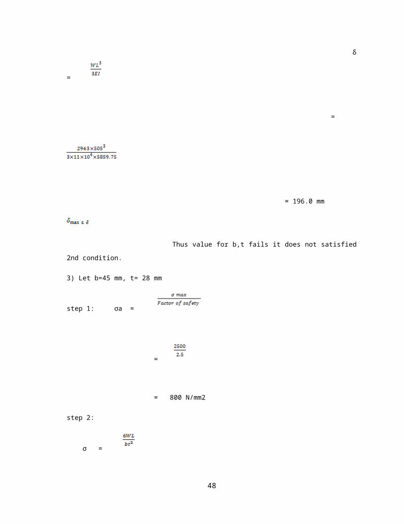
δ =
=
= 196.0 mm
Thus value for b,t fails it does not satisfied 2nd condition.
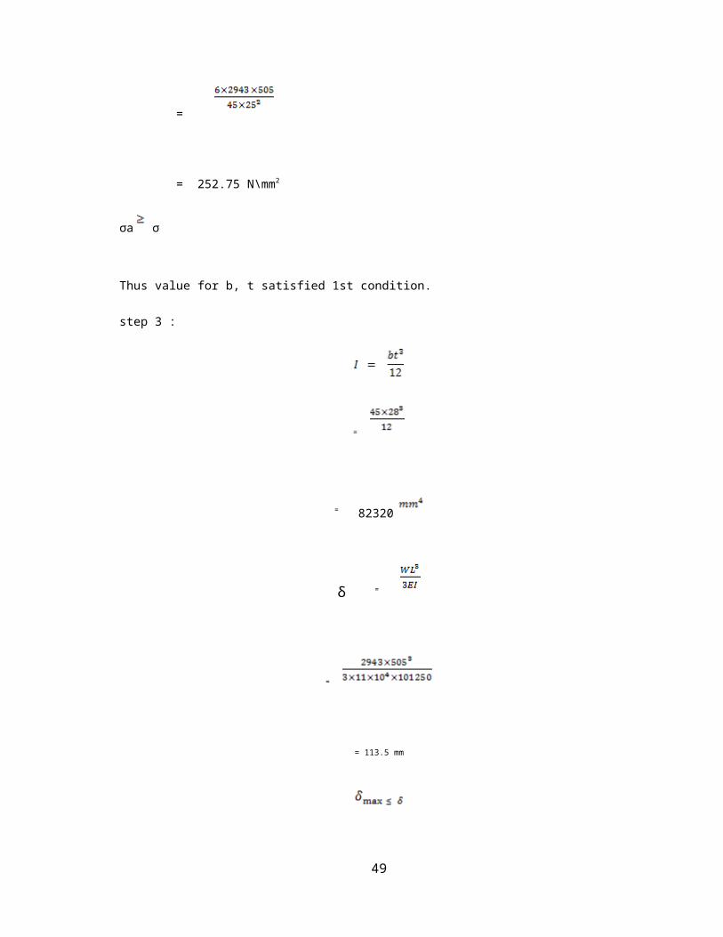
3) Let b=45 mm, t= 28 mm
step 1: σa =
=
= 800 N/mm2
37
step 2:
σ =
=
= 252.75 N\mm2
σa σ
Thus value for b, t satisfied 1st condition.
step 3 :
=
= 82320
δ =
=
= 113.5 mm
38
Thus value for b, t fails it does not satisfied 2nd condition.
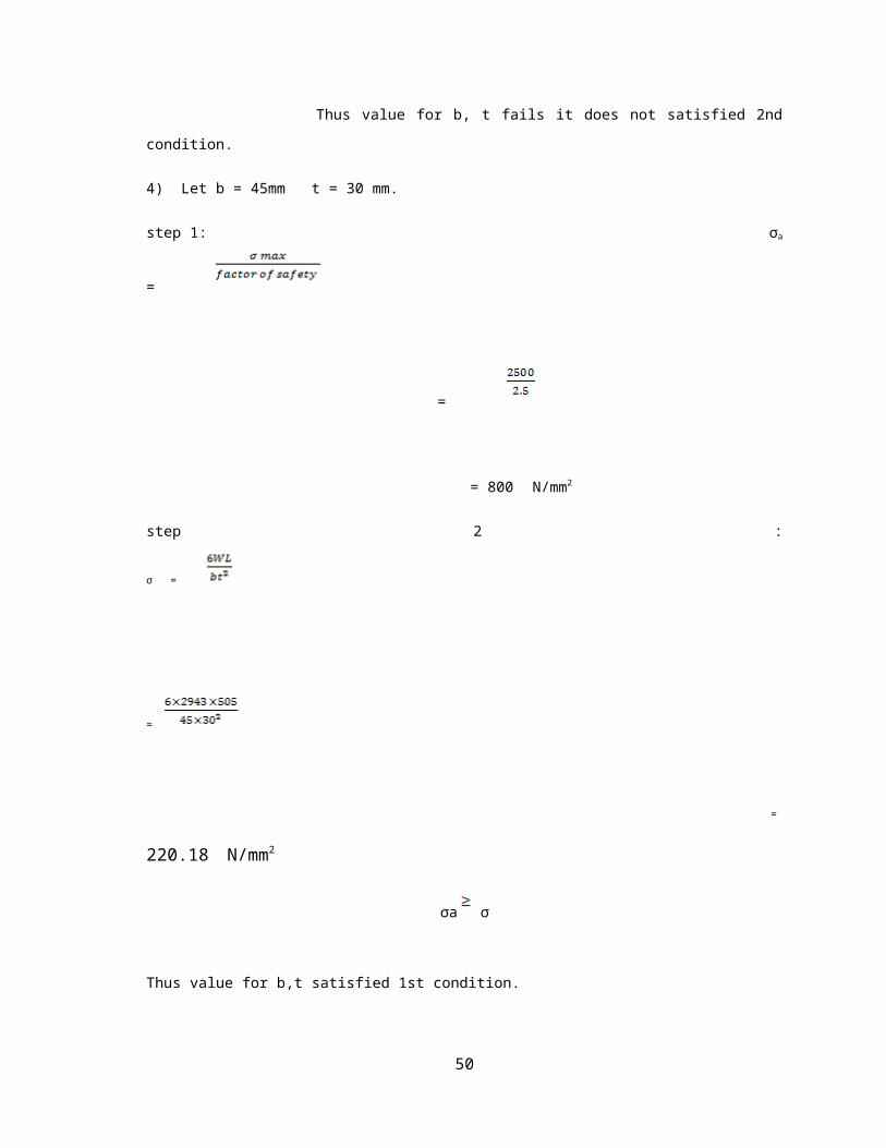
4) Let b = 45mm t = 30 mm.
step 1: σa =
=
= 800 N/mm2
step 2 : σ =
=
= 220.18 N/mm2
σa σ
Thus value for b,t satisfied 1st condition.
step 3:
=
39

= 101250 mm4
δ =
=
= 113.5 mm
Thus values for b,t satisfied 2 nd condition.
step 4 :
K =
K =
K = 26 N/mm
Thus value for b, t satisfied for 3 rd condition. Hence value b, t is safe.
Parameter Value
Length 505 mm
Width 45mm
Thickness 30 mm
40
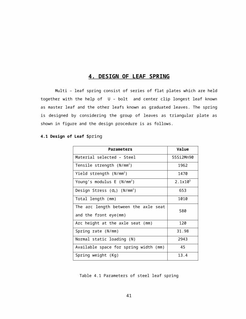
Table 4.3 Dimensions of composite leaf spring
For compare E-Glass-Epoxy Composite leaf spring and 60% jute composite leaf spring dimensions
of 60% Jute–E-Glass-Epoxy leaf spring are kept to be same as mentioned above.
5. FINITE ELEMENT ANALYSIS
Introduction of ANSYS
Ansys software is commercially available software which is capable of analyzing the given part by
means of structural, thermal, fluid, harmonic analysis.
5.1 Structural Static Analysis
Static structural analysis is a analysis in which the load condition does not vary with time & is
assumed that the load conditions are gradually applied. The most common application of FEA is the solution
of stress related design problems. As a result, all commercial available packages have extensive range of
stress capabilities.
The behavior of the system could be linear or non –linear.
From formal point of view, three conditions have to be met in any stress analysis, equilibrium of forces
or stresses, compatibility of displacements & satisfaction of the state of stress at continuum boundaries. The
kind of loads that a system could experience here are:
Forces or loads applied at one or at several points.
Pressure loads that can be distributed over one or multiple regions
Inertia loads applied due to motion as a result of velocity, acceleration or deceleration.
Thermal loads due to heat effect.
Specific displacement applied at one or more locations.
Outputs that can be expressed or expected in software are:
Displacement at one or more points.
Strains at one or more points.
Stresses at one or more points
Reaction forces.
5.2 Stages in ANSYS.
41
PREPROCESSOR
At the preprocessor level, several processors are available. Each processor is a set of functions that
perform a specific analysis task. Here we required to provide element type, real constants, and
material property as per the requirements. Then the process of meshing is performed.
SOLUTION
The FE solver can be logically divided into three main parts, the pre – solver, mathematical-engine,
post- solver. The pre-solver reads the model created by the pre-processor and formulates the
mathematical representations of the model. All the parameters defined in the post processing stage
are used to carry out above said task. If any parameter is given wrong the pre solver will complain
and abort the solution process. If the model is without any error the solver proceeds to form
element stiffness matrix for the problem and calls the mathematical engine which will calculate the
primary unknown results (displacement, temperature).The results are returned to the solver and post
– solver is used to calculate derived results (stress, strain, heat-fluxes, velocity )for each node
within the component. All these results are written to a file which may be read by post –processor.
POSTPROCESSOR
As discussed above the process of reviewing the result with the help of CAE tool is called post
processing .In this stage, the result of the analysis are read and interpreted .They can be represented
in the form of the table, a contour plot, deformed shape of the component or the mode shapes and
natural frequencies if frequency analysis is involved. Other results are available for fluid, thermal
and electrical analysis types. Most post processors provide an animation service, which produces an
animation.
5.3 Analysis of composite material
The model made up of composites materials are not directly developed for the composites materials
we feed data in matrix form or layered form.
Selecting the proper element type.
The following element types are available to model layered composite materials:
The type of element to be chosen depends upon the application, the type of results
to be calculated.
From above element SHELL99, SOLID 46 are best suited for the modeling of
composite material.
SHELL99
SHELL99 is an 8 – node, 3D shell element with six degrees of freedom
at each node. It is designed to model thin to moderate thick plate and
shell structures with side- to –thickness ratio of roughly 10 or greater.
SOLID 46
42
SOLID 46 is a layered version of 8 s- node, 3D element, SOLID 45 with
three degrees of freedom per node (UX, UY, UZ).It is designed to model
thick layered shells or layered solids and allows up to 125 layers with
thickness that may vary bilinear over the area of the layer. An advantage
with this element type is that you can stack several elements to model
more than 250 layers to allow through-the – thickness deformation slope
discontinuities. The user –input constitutive matrix option is also
available.SOLID46 adjusts the material properties in the transverse
direction permitting constant stress in the transverse direction. In
comparison to the 8 – node shells, SOLID46 is a lower order element and
finer meshes may be required for shell applications to provide the same
accuracy as SHELL91 or SHELL99.
From the above elements we have selected SOLID46 for the Analysis of
the leaf spring.
5.4 Procedure for performing a Static Analysis
The procedure for the static analysis consists of these tasks:
1. Build a Model
2. Mesh the Model
3. Apply the loads
4. Solve the Analysis
5. Review the Results.
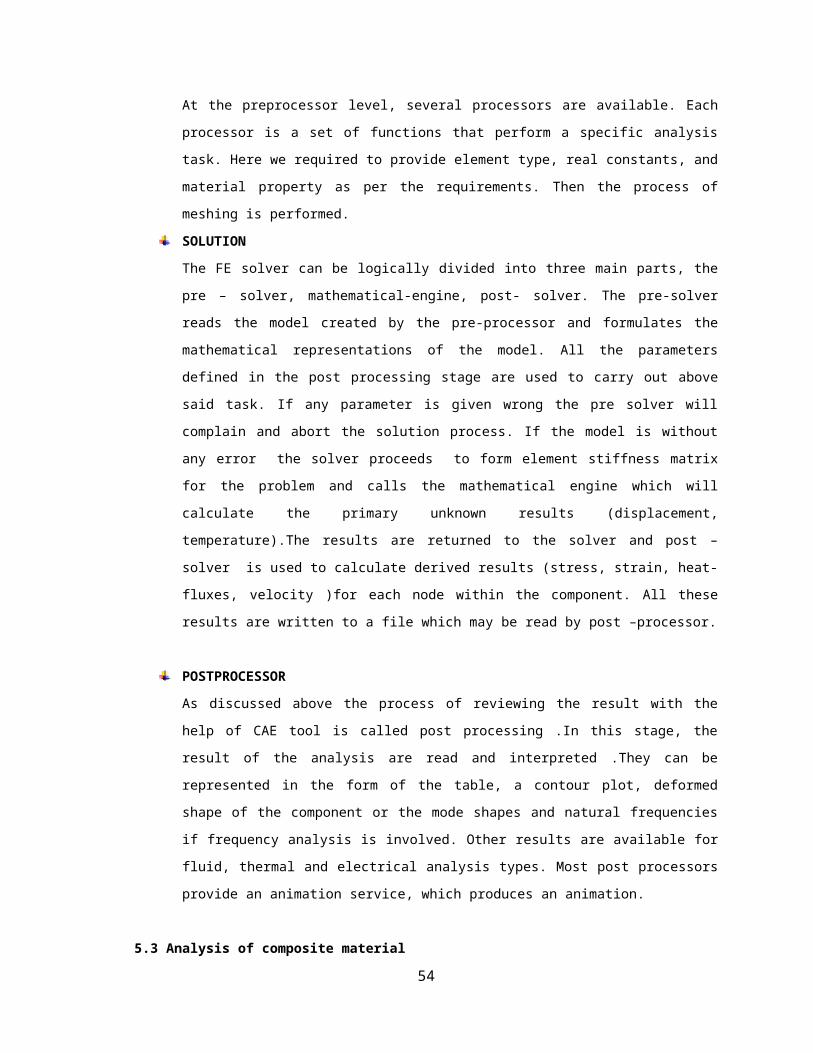
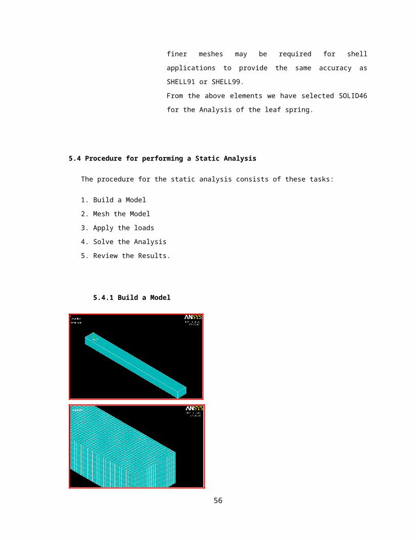
5.4.1 Build a Model
Fig 5.1 Finite element model Fig 5.2 Meshed model
43
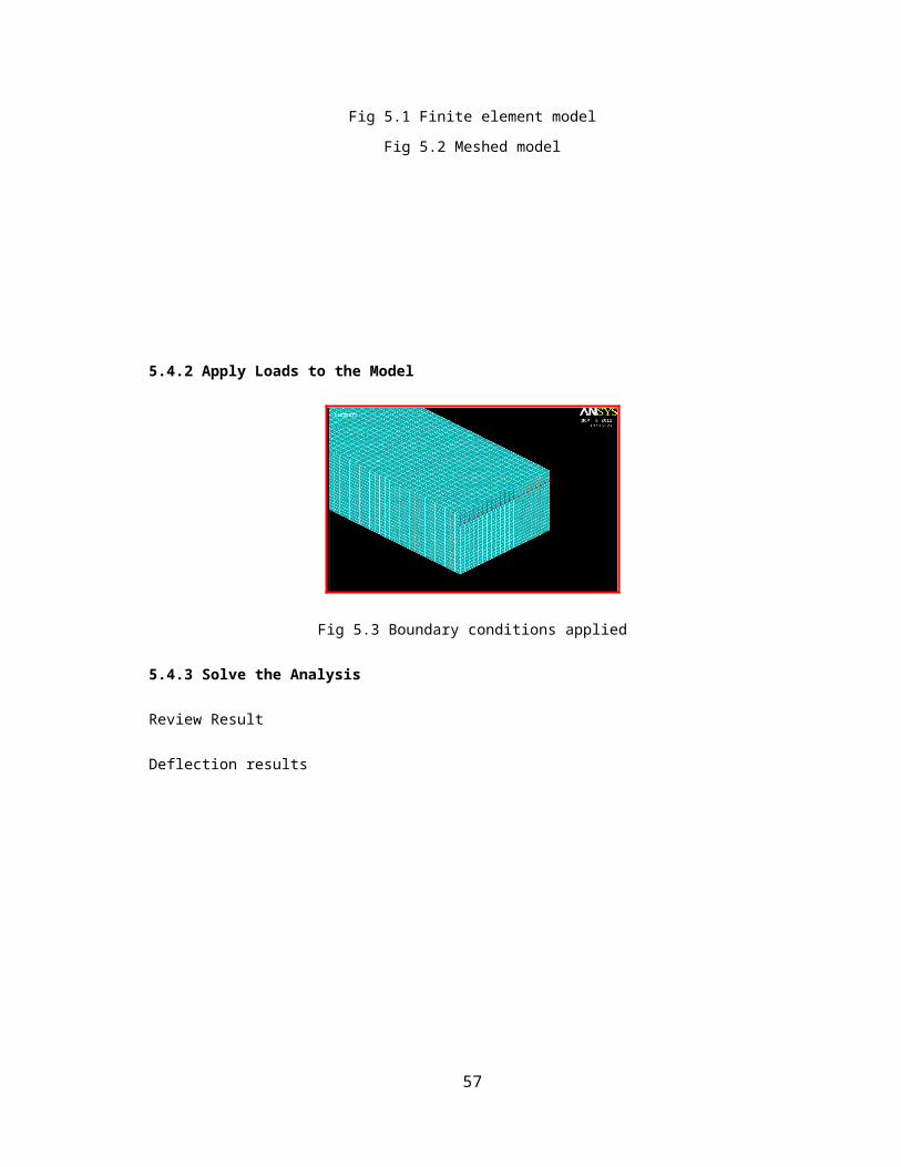
5.4.2 Apply Loads to the Model
Fig 5.3 Boundary conditions applied
5.4.3 Solve the Analysis
Review Result
Deflection results
Fig 5.4 Deflection along X direction Fig 5.5 Deflection along Y direction
5.4.4 Stress Results
44
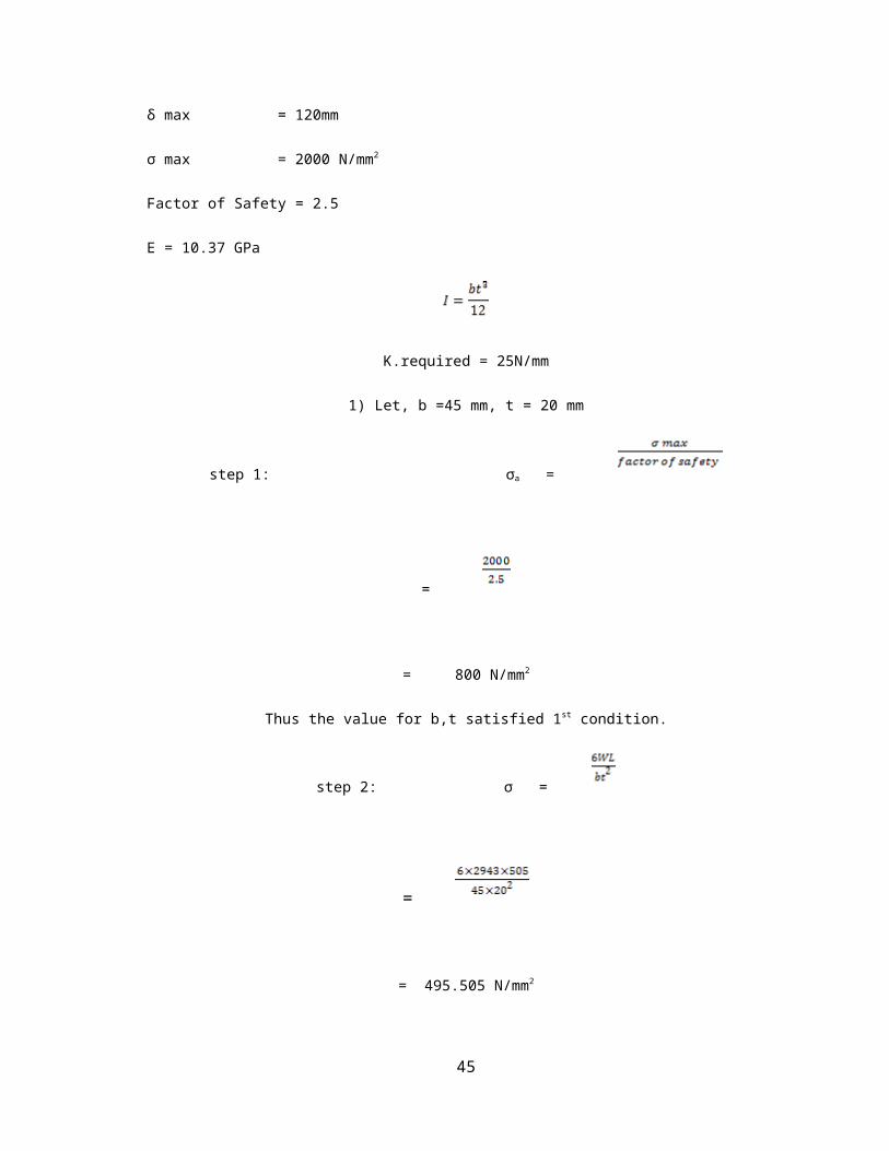
Fig 5.6 Stresses along X direction
Fig 5.7 Stresses along Y direction Fig 5.8 Stresses along Z direction
Results of Jute Glass epoxy composites
Fig 5.9 Deflection along X direction Fig 5.10 Deflection along Y direction
Results for Stresses
45

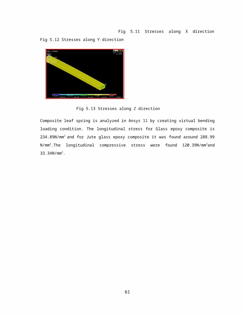
Fig 5.11 Stresses along X direction Fig 5.12 Stresses along Y direction
Fig 5.13 Stresses along Z direction
Composite leaf spring is analyzed in Ansys 11 by creating virtual bending loading condition. The
longitudinal stress for Glass epoxy composite is 234.89N/mm2 and for Jute glass epoxy composite it was
found around 288.99 N/mm2.The longitudinal compressive stress were found 120.39N/mm2and 33.34N/mm2.
46
6. FATIGUE ANALYSIS
6.1 Introduction
Fatigue is a phenomenon associated with variable loading or more precisely to cyclic stressing or
straining of a material. Just as human beings get fatigue when a specific task is repeatedly performed, in
similar manner metallic components subjected to variable loading get fatigue, which also leads to premature
failure under specific conditions.
Fatigue failure is a predominant mode of in service failure of many automobile components. This is
due to the fact that the automobile components are subjected to variety of fatigue loads like shocks caused
due to road irregularities traced by the road wheels, the sudden loads due to the wheel travelling over the
bumps etc. The leaf springs are more affected due to fatigue loads, as they are a part of the un- sprung mass
of the automobile.
Fatigue is a phenomenon in which a repetitively loaded structure fractures at a load level less than
its ultimate static strength. For instance, a steel bar might successfully resist a single static application of a
300KN tensile load, but might fail after 1,000,000 repetitions of a 200KN load.
Failure occurring under conditions of dynamic loading is called fatigue failure.
Fatigue failure is characterized by three stages.
Crack initiation
Crack propagation
Final fracture
6.1.1 What are the criteria for transition from crack initiation to crack growth life?
Life till crack of the size 2 mm detected is crack initiation life and remaining life after detection is
crack propagation or crack growth life.
47
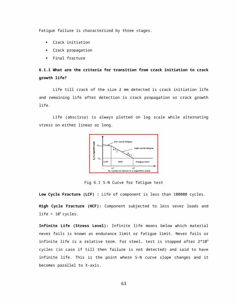
Life (abscissa) is always plotted on log scale while alternating stress on either linear or long.
Fig 6.1 S-N Curve for fatigue test
Low Cycle Fracture (LCF) : Life of component is less than 100000 cycles.
High Cycle Fracture (HCF): Component subjected to less sever loads and life > 105 cycles.
Infinite Life (Stress Level): Infinite life means below which material never fails is known as endurance
limit or fatigue limit. Never fails or infinite life is a relative term. For steel, test is stopped after 2*10 6 cycles
(in case if till then failure is not detected) and said to have infinite life. This is the point where S-N curve
slope changes and it becomes parallel to X-axis.
Unlike steel, non ferrous alloys have no specific endurance limit (S-N curve never become parallel
to X –axis).Pseudo – endurance limit for these materials is stress value corresponding to life = 5*10 s cycles
(something similar to proportionality limit for brittle materials).
S-N curve shown above is based on constant amplitude rotating bending test (Shaft subjected to
pure alternate bending stress).Similar test could be conducted for tension, compression, shear and torsional
stress. Bending fatigue strength is higher than tension/compression and torsional fatigue strength is the
lowest.
6.2 Factors affecting fatigue -life
Cyclic stress state : Depending on the complexity of the geometry and the load , one or more
properties of the stress state need to be considered, such as stress amplitude, mean stress,
biaxiality,in – phase or out-phase shear stress, and load sequence.
Geometry: Notches and variation in the cross section throughout a part to concentrations where
fatigue cracks initiate.
Surface quality: Surface roughness cause microscopic stress concentration that lower the fatigue
strength. Compressive residual stresses can be introduced in the surface by e.g. Shot Peening to
increase fatigue life. Such techniques for producing surface stress are often referred to as peening,
48
whatever the mechanism used to produce the stress. Low plasticity Burnishing, Laser Peening, and
Ultrasonic impact treatment can also produce this surface.
Compressive stress and can increase the fatigue life of the component. This improvement is
normally observed only for high – cycle fatigue.
Material Type: Fatigue life, as well as the behavior during cyclic loading, varies widely for
different materials, e.g. composites and polymers differ markedly from metals.
Residual stresses: Welding, cutting, casting and other manufacturing processes involving heat or
deformation can produce high levels of the tensile residual stress, which decreases the fatigue
strength.
Size and distribution of internal defects: Casting defects such as gas porosity, non-metallic
inclusions and shrinkage voids significantly reduce fatigue strength.
Direction of loading: For non-istropic materials, fatigue strength depends on the direction of the
principal stress.
Grain size: For most metals, smaller grains yield longer fatigue lives, however, the presence of the
surface defects or scratches will have a greater influence than in a coarse grained alloy.
Environment: Environment conditions can cause erosion, corrosion, or gas phase embrittlement,
which all affect fatigue life. Corrosion fatigue is a problem encountered in many aggressive
environments.
Temperature: Extreme high or low temperature can decrease fatigue strength.
6.3 Various Approaches in Fatigue Analysis
Fig 6.2 Various approaches for fatigue analysis
49
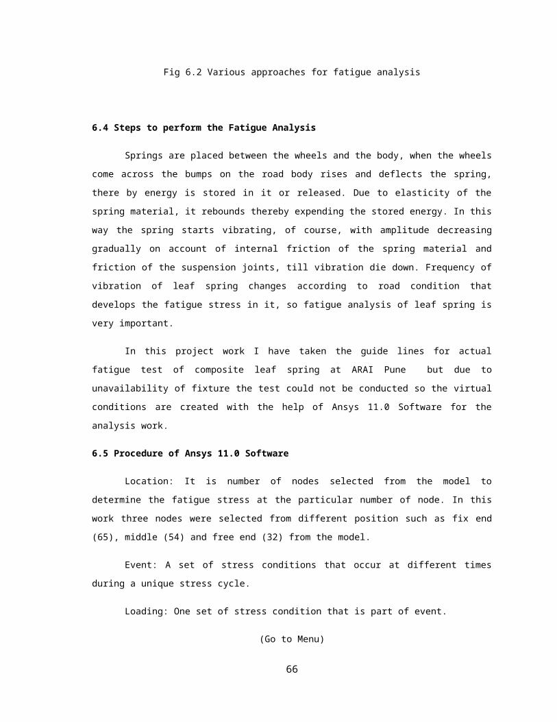
6.4 Steps to perform the Fatigue Analysis
Springs are placed between the wheels and the body, when the wheels come across the bumps on
the road body rises and deflects the spring, there by energy is stored in it or released. Due to elasticity of the
spring material, it rebounds thereby expending the stored energy. In this way the spring starts vibrating, of
course, with amplitude decreasing gradually on account of internal friction of the spring material and friction
of the suspension joints, till vibration die down. Frequency of vibration of leaf spring changes according to
road condition that develops the fatigue stress in it, so fatigue analysis of leaf spring is very important.
In this project work I have taken the guide lines for actual fatigue test of composite leaf spring at
ARAI Pune but due to unavailability of fixture the test could not be conducted so the virtual conditions are
created with the help of Ansys 11.0 Software for the analysis work.
6.5 Procedure of Ansys 11.0 Software
Location: It is number of nodes selected from the model to determine the fatigue stress at the
particular number of node. In this work three nodes were selected from different position such as fix end
(65), middle (54) and free end (32) from the model.
Event: A set of stress conditions that occur at different times during a unique stress cycle.
Loading: One set of stress condition that is part of event.
(Go to Menu)
General Postprocessor
Fatigue
Property Table
S-N Table
(Click N1)10(Click S1)62.1e3
(Click N2)1000(Click S1)62.1e3
(Click N1)10000(Click S1)52.1e3
(Click N1)100000(Click S1)42.1e3
50
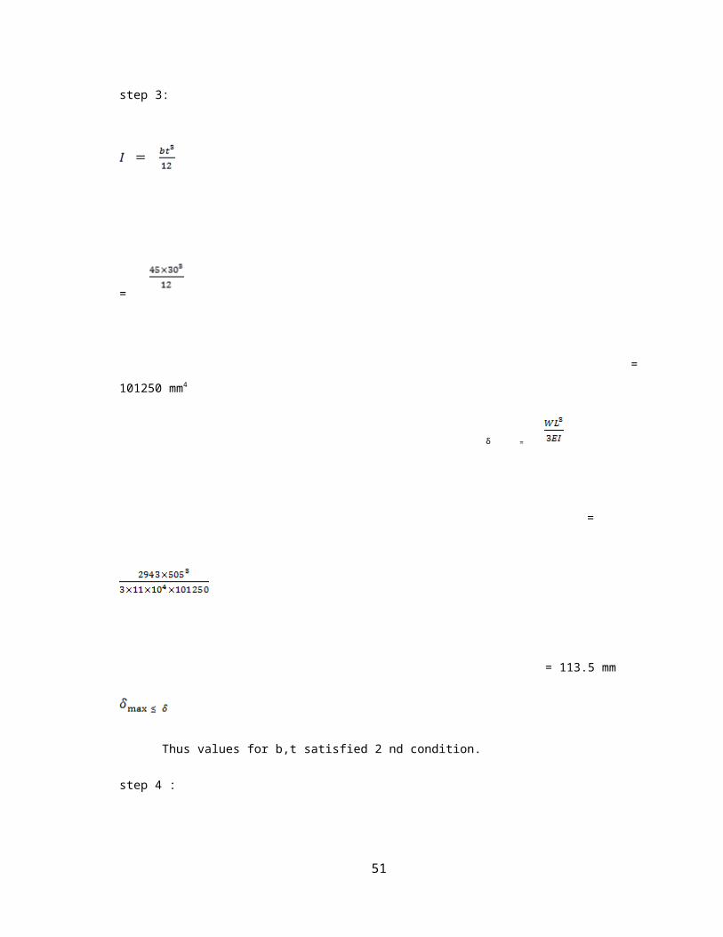
Fig 6.3 Step Load and Cycle application
(Go to Menu)
General Postprocessor
Fatigue
Calculate Fatigue
Specify Location Node Number
The result were obtained by using Ansys 11.0 by considering nodes 65,54 & 32 are as follows.
Fig 6.4 Fatigue stress at node 65 up to 100000 cycle
From the figure 6.4 combination of node 1 and 2, load1 and event 2 produces an alternating intensity
463.00N/mm2 for the cycle up to 100000 and allowable stress 371.89 N/mm2 and partial usage value that is
ratio of cycle used to allowable cycle is 0.99.
51

Fig 6.5 Fatigue stress at node 54 up to 100000 cycle
From the figure 6.5 combination of node 1 and 2, load1 and event 2 produces an alternating intensity
338.57N/mm2 for the cycle up to 100000 and allowable stress 227.23 N/mm2 and partial usage value that is
ratio of cycle used to allowable cycle is 1.
Fig 6.6 Fatigue stress at node 32 up to 100000 cycle
From the figure 6.6 combination of node 1 and 2, load1 and event 2 produces an alternating
intensity 748.91N/mm2 for the cycle up to 100000 and allowable stress 502.62 N/mm2 and partial usage value
that is ratio of cycle used to allowable cycle is 1.01.
From the fatigue stress with Ansys 11.0 Software is found to be 748.91 – 463.00 N/mm2 which is
less than designed allowable stress i.e. 800N/mm2 stress it mean design is safe for cyclic loading.
52
7. SELECTION OF MANUFACTURING PROCESS
7.1 Filament winding technique
Filament winding is used for producing symmetrical composite components if the production
volume and level of automation are high and the part is well designed. Filament winding is automated
process for creating constant thickness and constant width leaf spring where in continuous resin impregnated
fibers are wound over a rotating male tool called mandrel .In filament winding process where a continuous
fiber roving passes through shuttle, which rotates and the roving is wrapped around a revolving or stationary
mandrel
Fig 7.1 Filament Winding Technique
Advantages
Excellent mechanical properties due to use of continuous fibers.
53
High degree of design flexibility due to controlled fiber orientation and lower cost of large number
of composites.
This is a very fast and economic method of laying down material
Resin content can be controlled by metering the resin on to each fiber tow through nips or dies.
Disadvantages
Difficulty to wind complex shapes, which may require complex equipments.
Poor external finish
The process is limited to convex shaped components.
7.2 Hand Lay- up Technique/Wet lay up
The hand layup is one of the oldest and most commonly used methods for manufacture of the
composite parts. Hand layup composite are a case of continuous fiber reinforced composite. Layers of
unidirectional or woven composite are combined to result in a material exhibiting desirable properties in one
or more directions. Each layers oriented to achieve the maximum utilization of its properties. Layers of
different material (different fiber in different directions) can be combined to further enhance the overall
performance of the laminated composite material. Resin are impregnated by hand into fibers, which are in the
form of woven , knitted, stitched or bonded fabrics. This is usually accomplished by rollers or brushes, with
an increase use of nip –roller type impregnators for forcing resin into fabrics by means of rotating rollers and
a bath of resin. Laminates are left to cure under standard atmospheric conditions.
Fig 7.2 A Typical Hand Lay – Up Technique
Advantages
Design flexibility
Large and complex items can be produced.
54

Tooling cost is low.
Design changes are easily affected
Sandwich constructions are possible
Semi- skilled workers are needed
Higher fiber content and longer fibers than with spray lay- up.
Disadvantages
Only one molded surface is obtained
Quality is related to the skill of the operator
Low volume process
Longer cure times required
Resins need to be low in viscosity to be workable by hand. This generally compromises their
mechanical/thermal properties.
The waste factor is high.
A part from selection of material and design procedure, selection of manufacturing process also
determines the quality and cost of the product.
We can use filament winding machine as well as hand layup technique for manufacture of composite
leaf spring.
Requirements of manufacturing process
Method for manufacturing is easy.
Process must be economical
Complex shape can be produce by the process
A filament winding machine is used for large scale production. It requires a design and fabrication of
filament winding machine and it is very time consuming and complicated and this method is not as
economical as hand layup .Hand lay – up technique. Hand layup technique is used for small scale production
(2 to 3 specimen) and it is economical thus the hand layup technique is selected as manufacturing process.
7.3 FABRICATION PROCEDURE
7.3.1 Pre-procedure for fabrication
Preparation of mould
Material used – Plywood
Dimension for mould are as follows.
55
Parameters Value (mm)
Arc length 1160
Length 1010
Width 45
Arc height at the axle 130
Table 7.1 Dimension of Mould
Fig 7.2 Plywood Mould
Cut the glass fiber (stand chopped mat & woven roving) in to pieces according to the dimensions of
the mould with the help of cutter.
Clean the mould with the help of cloth.
Apply the wax polish (Manson) with the help of cloth on mould for better surface finish & for easy
removal of leaf spring after curing.
Preparation of Epoxy.
Fig 7.3 Applying the epoxy with the help of brush
56
Add 100ml acceleration in to the resin of 6 lit for increase the speed of reaction.
7.3.2 Procedure for the preparation of the composite leaf spring.
Prepare the solution of resin & hardener by adding 10-12% of hardener of required resin.
Place the piece of glass fiber chopped mat on mould
Apply the epoxy with the help of brush on glass fiber mat. The care should be taken that air is not
trapped.
Wait for 5-10min.
Again prepare the solution of resin & hardener.
Place layer of glass fiber woven roving on it.
Apply the epoxy with the help of brush. The care should be taken that air is not trapped between the
two layers.
Repeat the procedure up to attaining the desired thickness.
Cure the leaf spring for 24 hours.
Cut the extra fiber coming out of mould with the help of hacksaw
Remove the leaf spring from mould.
Fig 7.4 Prepared specimen of composite leaf spring
57

8. EXPERIMENTAL ANALYSIS
8.1 Universal Testing Machine (UTM)
Testing of composite & steel leaf spring has been carried on UTM. Various specifications of
UTM are as follows.
Make: Heico New Delhi
Model No: HL9C:10
Capacity: 20 Ton
Least weight: 10 kg
Maximum weight - 5 ton
Dial gauge least count: 0.01mm
8.2 Experimental Test
In the experimental analysis the comparative testing of mono composite leaf spring and natural
fiber reinforced composite leaf spring are taken. The deflection or bending stress of both the springs
for comparative study is taken on UTM.
58
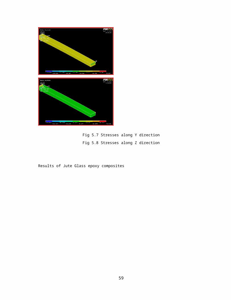
Fig 8.1 Load applied on Composite leaf spring
8.2.1 Experimental test for Glass reinforced composite leaf spring
8.2.1.1 Procedure
Move the plunger up to the desired height so that we can fix the fixture and leaf spring for
the test.
Fix the position of the fixture.
On the fixture place the specimen
Set the universal testing machine
Apply the loads in steps of 50kg gradually
Note down the deflection readings
The results obtained during the experiment on the Glass Reinforced leaf spring are listed in the following
table
Sr.no Applied load(kg) Deflection of E –Glass composite leaf spring
1 50 05
2 100 15
3 150 23
4 200 36
5 250 41
6 300 63
7 350 69
8 400 78
Table 8.1 Deflection at different load on composite material leaf spring
8.2.2 Experimental test for Natural fiber reinforced composite leaf spring
8.2.2.1Procedure
59

Move the plunger up to the desired height so that we can fix the fixture and leaf spring for
the test.
Fix the position of the fixture.
On the fixture place the specimen
Set the universal testing machine
Apply the loads in steps of 50kg gradually
Note down the deflection reading.
The results obtained during the experiment on the Jute – Glass- Reinforced-Composite leaf spring
are listed in the following table
Table 8.2 Deflections at different load on natural fiber composite leaf spring
60
Sr.no Applied load(kg) Deflection of Jute -E – Glass
composite leaf spring
1 50 04
2 100 17
3 150 32
4 200 37
5 250 65
6 300 89
7 350 102
8 400 460/break/110
9. COMPARISION BETWEEN GLASS FIBER REINFORCED
COMPOSITE & NATURAL FIBER REINFORCED COMPOSITE
LEAF SPRING (JUTE)
Glass fiber reinforced composite leaf spring and natural fiber based composite leaf spring were
tested on Universal Testing Machine(UTM).Following tables and graphs shows the comparison of spring
deflection, stiffness, weight and stress of glass fiber reinforced composite leaf spring and natural fiber
reinforced composite spring (Jute- Glass-Epoxy composite leaf spring).
9.1 Comparison of Deflection of glass fiber reinforced and jute fiber reinforced composite leaf spring
(Experimental)
Sr.no Applied
loads
Deflection of E glass
composite leaf spring
Deflection of jute glass epoxy
composite leaf spring
1 50 05 04
2 100 15 17
3 150 23 32
4 200 36 37
5 250 41 65
6 300 63 93
7 350 69 102
8 400 78 460/break/110
Table 9.1 Comparison of Deflection of glass fiber reinforced and jute fiber reinforced composite leaf spring
(Experimental)
61
Graph 9.1 Comparison of Deflection of Glass and Jute Fiber Reinforced Epoxy Composite Leaf Spring.
9.2 Comparison of stiffness of glass fiber and jute fiber reinforced composite leaf spring
Sr.no Applied load Stiffness(N/mm) of E-glass
composite leaf spring
Stiffness(N/mm) of jute Glass
epoxy composite leaf spring
1 50 98.1 122.62
2 100 65.4 57.70
3 150 63.95 45.98
4 200 59.45 53.03
5 250 55.73 37.73
6 300 54.5 31.64
7 350 52.03 33.66
8 400 50.96 35.67
Table 9.2 Comparison of stiffness for Glass epoxy composite and Jute glass epoxy composite leaf spring
62
Graph 9.2 Comparison of stiffness for Glass epoxy composite and Jute glass epoxy composite leaf spring
9.3 Comparison of Weight glass fiber composite leaf spring and jute fiber based composite leaf
spring
Sr.no Weight of E – glass composite
leaf spring
Weight of Jute E – glass composite
leaf spring
1 3.85kg 2.730kg
Table 9.3 Comparison of Weight glass fiber composite leaf spring and jute fiber based composite leaf spring
9.4 Comparison of stress of GFRP and NFRC (Jute based) in Mpa
Leaf spring Analytical Numerical (FEA)
COMPOSITE 220.18 234.38
JUTE –E-GLASS-COMPOSITE 220.18 288.99
Table 9.4 Comparison of stress of GFRP and NFRC (Jute based)
63

10. CONCLUSION
Experimental results from testing the leaf spring under static loading condition the stresses and
deflections are calculated. These results are compared with FEA. Testing has been done for unidirectional E-
Glass Epoxy composite leaf spring and jute E Glass epoxy composite leaf spring. Since the composite leaf
springs are able to withstand the static load, it is concluded that there is no objection from strength point of
view in the process of replacing the conventional leaf spring by GFRP and Jute glass epoxy leaf spring.
Since, the FRP leaf springs designed for same stiffness as that of steel leaf spring. GFRP and Jute glass
epoxy composite are considered to be almost equal in vehicle stability and both are manufactured with same
dimensions. The major disadvantage of GFRP and Jute Glass Epoxy composite leaf spring are chipping
resistance. The matrix material is likely to chip of when it is subjected to poor road condition(that is ,if some
stone hit the composite leaf spring then it may produce chipping)which may break some fibers in lower
portion of the spring. This may result in a loss of capability to share flexural stiffness. But this depends on
the condition of road. In normal road condition, this type of problem will not exist. GFRP leaf and Jute glass
epoxy composite leaf spring made of polymer matrix composite have high strength retention on aging at
severe environments.
The objective was to fabricate and analyze the springs with minimum weight which is capable of
carrying given static external forces by constraints limiting stresses and displacement. The weight of the leaf
spring is reduced considerably about 75% by replacing steel and GFRP and Jute-E-Glass-Epoxy composite
leaf spring thus, the objective of reducing the un-sprung mass is achieved to a larger extent. The stresses in
the composite leaf spring are much lower than that of the steel.
64

FUTURE SCOPE
In future we can use some other bio-materials such as cotton, wheat straw, coconut,
coir etc, as a reinforcement material along with E-Glass/Carbon/S-Glass fiber:
As in our project work Jute-E-Glass-Epoxy fiber is used as a reinforcement material
instead of jute fiber other bio- materials such as cotton/flax/coconut coir etc.and instead of
E-Glass some Carbon, S-Glass fiber can be used as a reinforcing material. So in future we
can use such a material for the comparison performance of the steel leaf spring and bio-
composite leaf spring.
Study of effects of different resins on the performance of leaf spring:
In our project General Purpose resin is used for manufacturing the leaf spring instead of
GPR polyester, vinyl ester etc. can be used to study effects of different resin on the
performance of composite leaf spring.
Study of effects of temperature on the stress and strain of the leaf spring material:
As environment temperature increases, the stresses of E-Glass fiber get reduced hence the
effect of temperature on the performance of the spring material is an important part of
study.
Study of prevention for the maintenance is a very important concept of composite
material leaf spring:
The preventive maintenance is a very important concept for application work so in future
we can study preventions for composite leaf spring.
65
REFERENCES
1. Shiva Shankar, Vijayarangan, “Mono Composite Leaf Spring for Light Weight Vehicle Design, End
Joint Analysis and Testing” Materials Science Vol. 12, No. 3. 2006 ISSN 1392-1320
2. X.Y.Liu, G.C.Dai “ Surface modification and micromechanical properties of jute fiber mat
reinforced polypropylene composites” express polymer letter vol.1,no 5(2007) p.n.- 299-307
3. I. Rajendran, S. Vijayarangan “Optimum design of a composite leaf spring using genetic
algorithms” Computer and structures 79(2001) p.n. 1121-1129
4. Anthony Kelly “Composite after seventy years” J MATER SCI 41 (2006) 905–912,
5. H.M.M.A. Rashid, M.A.Islam, F.B.Rizivi “Effect of process parameters on tensile strength of jute
fiber reinforced thermoplastic composite” Journal of Naval Architecture and Marine Engineering
June 2006
6. Saira Taj, Munawar Ali, hafiullah Khan “Natural fiber reinforced polymer composite” Proc.
Pakistan acad. Sci. 44(2); 129-144:2007
7. J.P. Hou, “Evolution of the eye-end design of a composite leaf spring for heavy axle loads”
Composite Structures 78 (2007) pp 351–358
8. Hiroyuki Sugiyama, Ahmed A. Shabana , Mohamed A. Omar “Development of nonlinear
elastic leaf spring model for multi body vehicle systems” Composite Methods Appl. Mech.
Engineering. 195 (2006) 6925–6941
9. Mouleeswaran Senthil Kumar, Sabapathy Vijayarangan, “Analytical and Experimental Studies on
Fatigue Life Prediction of Steel and Composite Multi-leaf Spring for Light Passenger Vehicles
Using Life Data Analysis” Materials Science (MEDZIAGOTYRA). Vol. 13, No. 2. 2007, ISSN
1392– 1320.
10. S.V.Joshi,L.T.Drzal,A..Mohanty, S.Arora “Are Natural fiber composites environmentally superior
to glass fiber reinforced composites?”
11. Kamal Sethi “Investigation of damaged glass fiber reinforced composite in three point bending” M-
tech thesis Thapar Institute of Engineering and Technology, Patiala.
66

12. James Holbery and Dan Houstan “Natural fiber reinforced polymer composites in automotive
application” JOM Nov.2006 p.p. 80-86
13. Yu WJ, Kim HC “Double tapered FRP beam for automotive suspension leaf spring” Composite
Structures 1988; 9(4):279-300.
14. A.Al-Qureshi, Automobile leaf spring from composite materials” Journal of Material Processing
Technology 118 (2001)pp 58-61.
15. T.Kevin O’Brein, Arun D.Chawan , Ronald Krueger, Isabelle L.Paris “Transverse tension fatigue
life characterization through flexture testing of composite materials” International Journal of
Fatigue 24(2002)127-145
16. Mahmood M.Shokreih, Davood Rezaei “Analysis and optimization of a composite leaf spring”
Composite Structures 60 (2003)pp 317-325
17. M.Senthil Kumar, S.Vijayarangan “Static analysis and fatigue life prediction of steel and composite
leaf spring for light passenger vehicle” Journal of Scientific &Industrial Research Vol .66 Feb.2007
pp128-134.
18. Carlo Santulli “Impact properties of glass/plant fiber hybrid composite” Journal of Material
Science (2007) 42 pp 3699-3707
19. Dr.Kirpal Singh, “Automobile Engineering”, Standard Publishers, Volume-1.pp 204-208
20. R.S.Khurmi &J.K.Gupta “Machine Design” S Chand Publishers Multi Colored Addition First pp
822-884.
21. Navin Chand & Mohammed Fahim “Tribology of Natural Fiber Polymer Composites”Woodhead
Publishing and Maney Publishing on behalf of The Institute of Materials, Minerals & Mining.
67