Embed Size (px)
Citation preview

COMPOSITE END-FITTINGS FOR LIGHTWEIGHT
TELESCOPE APPLICATIONS
F. Ernesto Penado, Scott T. Broome Department of Mechanical Engineering
Northern Arizona University, Flagstaff, AZ 86011
Robert C. Romeo, Robert N. Martin Composite Mirror Applications, Inc.
1638 S. Research Loop, Tucson, AZ 85710
James H. Clark, III Naval Research Laboratory/ Navy Prototype Optical Interferometer
Naval Observatory Flagstaff Station 10391 Observatory Road
Flagstaff, AZ 86001
Joshua P. Walton Interferometrics Incorporated/ Navy Prototype Optical Interferometer
Naval Observatory Flagstaff Station 10391 Observatory Road
Flagstaff, AZ 86001
ABSTRACT Recent developments in lightweight, dimensionally-stable, portable telescopes have required the application of advanced materials. For example, composite telescopes with 0.4- and 1.4- meter primary mirrors are currently being developed for use at the Naval Prototype Optical Interferometer (NPOI). By fully utilizing composite construction for telescope elements such as optics, structure, mount, and end-fittings, the overall weight has been reduced nearly an order of magnitude over conventional designs. Furthermore, composite end-fittings reduce weight and increase stiffness at the secondary end of a telescope. Compared to their metallic counterparts, composite end-fittings contribute to reduced inertia, enhanced response, and improved performance. In this paper, details for the design and manufacturing procedure of a lightweight composite end-fitting for a telescope application are presented. The structural integrity of the end-fitting was verified by means of finite element analysis. It is shown that the use of composite materials provides significant weight savings over comparable end-fittings made of metal, in addition to a near zero coefficient of thermal expansion. KEY WORDS: Advanced Composite Structures, Dimensional Stability, Joint Design and Analysis
1. INTRODUCTION
Advancements in the emerging field of optical interferometry can be further realized by the use of larger diameter telescopes. Optical interferometry employs a multiple telescope array to create a large synthetic aperture. This results in the same resolution as an equivalent single, huge diameter telescope. The advantage of interferometry is that manufacture of multiple smaller telescopes is much more feasible and less costly than a single huge telescope. Although interferometry comes at the expense of reduced sensitivity, this can be increased by increasing the diameter of the individual telescopes in the array. Figure 1 shows an aerial view of the Navy Prototype Optical Interferometer (NPOI) which has a potential resolution of a 437 meter diameter telescope.
Figure 1. Aerial View of the Navy Prototype Optical Interferometer. (Photo Courtesy of Michael Collier.)
Portability, reliability (stiffness, stability, durability, and corrosion resistance), and economics are desired characteristics of telescopes for use in interferometric arrays. The NPOI is developing large telescopes that have 1.4 meter diameter individual telescopes in order to increase the sensitivity over the existing 0.13 meter apertures. Reduction in telescope mass assists with portability and is therefore a necessary design consideration. Furthermore, the complex nature of optical interferometry (synchronous use of multiple telescopes) dictates the requirement for high reliability of each component. Finally, since the NPOI utilizes multiple telescopes, it is important to reduce the overall cost per telescope. It is expected that an all-composite telescope construction will be less expensive than traditional telescope fabrication when taking into account production of multiple units. In consideration of the aforementioned desired characteristics, Carbon Fiber Reinforced Polymer (CFRP) materials provide a natural choice as the primary material for the entire telescope, including the optics, mount, structure, and end-fittings. Figure 2a illustrates the basic components of an all composite telescope currently under consideration.

(a) (b) Figure 2. (a) A composite telescope with a 1.4 meter diameter mirror.
(b) Typical truss-tube assembly showing an end-fitting. End-fittings are a critical component of the telescope design. The main function of the end-fittings is to provide a reliable mechanical transition at the ends of truss tubes. The resulting truss tube assembly joins the primary optic to the secondary optic while maintaining stringent focal length and tip/tilt alignment over a wide temperature range (-25°C to +30°C). Allowable changes of length due to thermal effects are only on the order of tens of micro-meters. Additionally, thermal stresses induced by the expected temperature swing must be consistent with the strength of the resulting composite end-fitting and truss tube assembly. If not, probability of failure increases. Figure 2b shows the major components of a typical end-fitting and truss-tube assembly. The coefficient of thermal expansion (CTE) mismatch, overall strength, and reduced potential for galvanic corrosion can be improved by specifically tailoring the CFRP layup to this application. The end-fittings are fabricated from similar materials as the truss tube. The low weight and high stiffness of the truss tube assembly better achieves the desired overall characteristics of the telescope. The use of continuous fibers enhances end-fitting strength and creates a continuous stress flow throughout the truss tube assembly during static, dynamic, and thermal loadings. Compared with traditional telescope construction, the all-CFRP telescope enhances dynamic performance due to reduced inertial mass and increased stiffness, achieves greater optical stability due to tailored CTE’s, and reaches thermal equilibrium at a faster rate. This paper focuses on the design, analysis, and manufacturing procedure of CFRP end-fittings for structures such as the NPOI 1.4-meter diameter telescope.
2. MATERIAL SELECTION AND PROPERTIES
2.1 Material Selection Standard use of the 1.4 meter telescope requires that the following two loading conditions are imposed on the end-fitting: 1) thermal loading and, 2) static tension and compression. A GRAFIL 34-600/BT250 carbon/epoxy system was chosen, due to its relatively

high strength and stiffness. This material system also provides a low coefficient of thermal expansion, thus minimizing thermal stresses and deformations. 2.2 Material Properties A suite of tests designed to determine the lamina properties of the end-fitting material was performed. ASTM standards [1] were followed for all sample preparation and testing operations with five samples of each test type performed for statistical validation. The test results are shown in Table 1. 2.2.1 0° and 90° tensile E1, ν12, sL
(+), E2 and sT(+) were determined from longitudinal (0°) and
transverse (90°) tensile testing. For all stiffness and strength testing, load cell and strain gage data were collected by an acquisition system sampling at 5 Hz. Figure 3a shows the test setup for a typical 0° tensile test. The axial tensile coupon, composed of six unidirectional plies, was stressed in the fiber direction (0°) until failure. The longitudinal tensile coupon, composed of 16 unidirectional plies, was stressed transverse to the fiber direction (90°) until failure. A 0°/90° strain gage rosette was bonded to each specimen to monitor the axial and transverse strains. 2.2.2 0° and 90° compression sL
(-) and sT(-) were determined from longitudinal (0°) and
transverse (90°) compression tests. Figure 3b shows the test setup used for a typical 0° compression test (IITRI fixture). The 0° and 90° coupons, composed of 20 and 32 unidirectional plies, respectively, were compressed until failure. In order to monitor for bending, strain gages were attached to both sides of the samples. 2.2.3 Iosipescu shear G12 and sLT were determined from the Iosipescu shear test shown in Figure 3c. The coupons were composed of 20 unidirectional plies with two 3.8-mm deep 90° ‘V’ grooves machined into the top and bottom in the center of the sample and were sheared to failure. Shear pattern strain gages were bonded to each sample on both sides to monitor twisting effects.
(a) (b) (c)
Figure 3. Experimental setup. a) 0° tensile coupon. b) IITRI fixture showing 0° compression coupon. c) Iosipescu shear test.
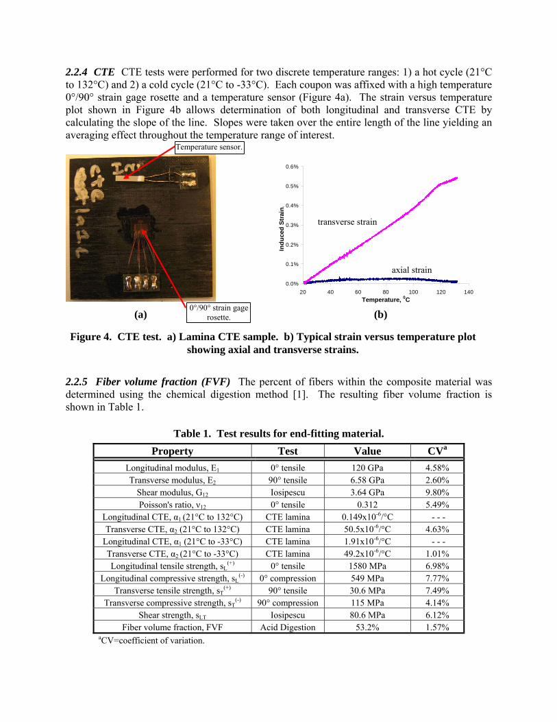
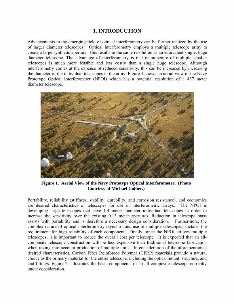
2.2.4 CTE CTE tests were performed for two discrete temperature ranges: 1) a hot cycle (21°C to 132°C) and 2) a cold cycle (21°C to -33°C). Each coupon was affixed with a high temperature 0°/90° strain gage rosette and a temperature sensor (Figure 4a). The strain versus temperature plot shown in Figure 4b allows determination of both longitudinal and transverse CTE by calculating the slope of the line. Slopes were taken over the entire length of the line yielding an averaging effect throughout the temperature range of interest.
(a)
0.0%
0.1%
0.2%
0.3%
0.4%
0.5%
0.6%
20 40 60 80 100 120 140Temperature, 0C
Indu
ced
Stra
in, %
Axial ecTransverse ec
y = 5.01E-05x - 1.07E-03
y = 4.30E-07x + 1.00E-04
Temperature sensor.
0°/90° strain gage rosette. (b)
axial strain
transverse strain
Figure 4. CTE test. a) Lamina CTE sample. b) Typical strain versus temperature plot showing axial and transverse strains.
2.2.5 Fiber volume fraction (FVF) The percent of fibers within the composite material was determined using the chemical digestion method [1]. The resulting fiber volume fraction is shown in Table 1.
Table 1. Test results for end-fitting material. Property Test Value CVa
Longitudinal modulus, E1 0° tensile 120 GPa 4.58% Transverse modulus, E2 90° tensile 6.58 GPa 2.60%
Shear modulus, G12 Iosipescu 3.64 GPa 9.80% Poisson's ratio, ν12 0° tensile 0.312 5.49%
Longitudinal CTE, α1 (21°C to 132°C) CTE lamina 0.149x10⁻⁶/°C - - - Transverse CTE, α2 (21°C to 132°C) CTE lamina 50.5x10⁻⁶/°C 4.63%
Longitudinal CTE, α1 (21°C to -33°C) CTE lamina 1.91x10⁻⁶/°C - - - Transverse CTE, α2 (21°C to -33°C) CTE lamina 49.2x10⁻⁶/°C 1.01% Longitudinal tensile strength, sL
(+) 0° tensile 1580 MPa 6.98% Longitudinal compressive strength, sL
(-) 0° compression 549 MPa 7.77% Transverse tensile strength, sT
(+) 90° tensile 30.6 MPa 7.49% Transverse compressive strength, sT
(-) 90° compression 115 MPa 4.14% Shear strength, sLT Iosipescu 80.6 MPa 6.12%
Fiber volume fraction, FVF Acid Digestion 53.2% 1.57% aCV=coefficient of variation.

3. DESIGN AND MANUFACTURING
3.1 Design of the End Fitting In the design of a telescope like the one discussed herein, lightweight, high stiffness and low thermal expansion are desirable attributes. In addition, material compatibility between the fittings and the truss tubes results in lower mechanical and thermal stresses and reduces the possibility of galvanic corrosion as when the end-fittings are made of metal. A [45/02/-45/0]s layup was chosen to optimize the desired axial properties while still maintaining high strength and stiffness in the circumferential direction. In order to illustrate some of the relative merits of using end-fittings made of composite materials instead of metal, Table 2 presents a comparison between the present end fitting and similar alternative designs using aluminum or titanium.
Table 2. Properties of the composite end-fitting and its metallic counterparts.
Material Density, ρ (g/cm3)
Axial modulus, Ex (GPa)
Axial strength, sL (MPa)
Axial CTE, αx (x10-6/°C)
[45/02/-45/0]s GRAFIL 34-600
/BT250a 1.54b 77.7c
917d (tension)
273d
(compression)
-0.495c
(21°C to 132°C)
1.31c
(21°C to -33°C) Aluminum (7075-T6) 2.80 72 500 (yield)
570 (ultimate) 23.6
Titanium alloy (6% Al, 4% V) 4.73 115 830 (yield)
900 (ultimate) 9.5 aPly thickness=0.2 mm. bFrom rule of mixtures. cFrom laminated plate theory. dEstimated from progressive failure.
The properties in Table 2 clearly show that the composite layup chosen for the end-fitting is significantly lighter and stronger in tension that either aluminum or titanium, although not as strong in compression. In addition, it is stiffer than aluminum but not as stiff as titanium. Finally, the coefficient of thermal expansion of the end-fitting material in the axial direction is close to zero and is much lower than that of either titanium of aluminum. Overall, the properties that can be achieved by using composites make these materials an ideal choice for the telescope application. 3.2 Manufacturing of the End-Fitting The manufacturing approach used to produce the end-fittings was based on the use of high and uniform pressure distribution on the consolidation and curing phases. It is essential to create a uniform consolidation pressure to minimize the void content of the resulting part. The procedure used to manufacture the end-fitting and achieve good consolidation and quality is detailed next.

3.2.1 Tooling A set of male-female conical dies allows for the end of the layup to be uniformly pressed. This produces a high and uniform pressure distribution throughout the conical layup. The dies were machined from 6061-T6 aluminum-alloy bar stock. The tooling set is shown in Figure 5a.
(a) (b)
Figure 5. (a) Male and female tools for end fitting manufacturing. (b) Layup of prepreg over the male tool (white is the release paper and illustrates the
shape of each gore section of a particular ply).
3.2.2 Layup The base-layup is 10 plies at [45/02/-45/0]s. An additional thickness buildup is placed on the inside of the flat, end portion of the fitting to form a built-in “composite washer” for reinforcement. The layup of this composite washer is [0/±45/90]3s. Figure 5b shows 1 of 10 gores that make up a single ply of the end fitting. The gores are placed side to side around the circumference of the mandrel with no overlap. The next ply gores are started by overlapping a seam from any 2 gores of the previous ply. This helps to place the cut edges of the gores out of phase for each of the 10 plies. 3.2.3 End Fitting Consolidation Once all 10 plies are applied to the male tool of a given end fitting a small aluminum end cap is placed onto the end of the layup for end consolidation. The entire layup is placed inside of the female tool and the assembly is placed under clamping pressure (see Figure 6). Pressure is applied via a bolt at the end of the clamping assembly. This forces the male tool and layup into the female tool. The aluminum end cap is then pressed against the end of the layup to consolidate this region. This achieved by tightening an eye-bolt from the female tool side.

(a) (b)
Figure 6. (a) Clamping fixture with tools and laminate in place. (b) Close-up of bolt used to produce the axial clamping force.
Because of the two different cross sections of the end fitting (conical and cylindrical), two different consolidation methods are required. The conical end consolidation has just been described. The cylindrical section, which slides over the strut tube must be consolidated via shrink tape. Consolidation is achieved through the 5% shrinkage in the polyester tape creating a radial pressure on the cylindrical portion of the end fitting. Once assembled, the entire setup is placed in an oven and cured according to the matrix requirements. 3.2.3 Completed End Fitting Once released from the male tool, the composite end fitting is trimmed to length, which allows for at least 50 mm of a cylindrical bond to the strut tube. The end-fitting is adhered to the outside end of the strut tube with structural adhesive having a bond thickness of 0.125 mm. Machining is then done to accommodate the end fitting attachment hardware. The end fittings manufactured by this process are shown in Figure 7.
Figure 7. (a) End fittings attached to the strut tubes, including their connecting hardware. (b) End fittings in place on the telescope head ring.
(a) (b)

4. FINITE ELEMENT ANALYSIS
In order to verify the structural integrity of the fitting under the applied loads, a finite element model of the fitting was run using COSMOS/M. The mesh, loading, and boundary conditions used are shown in Figure 8. Due to the axial symmetry of the fitting, only a 30° segment was needed in the model.
Figure 8. Finite element mesh, loading and boundary conditions used in the model of the end fitting. Cyclic symmetry boundary conditions were used.
30° segment due to axial symmetry
P (compression)
P (tension)
A distributed load totaling P=89 N applied in order to
determine the factor of safety
Cyclic symmetry boundary conditions used
at the radial edges
Axial displacement =0 at the edge
The model consisted of 1660 4-noded shell elements corresponding to the composite shell, and 3000 8-noded solid elements corresponding to the composite washer. Two types of loads were considered: mechanical and thermal. The mechanical loads are due to the axial forces in the tubes, and the thermal loads occur due to the mismatch of coefficient of thermal expansion between plies. The temperature range considered was -35°C to 65°F, which corresponds to the range of temperatures that the telescope may experience in service at the NPOI site in Flagstaff, Arizona. The -35 °C temperature corresponds to the lowest temperatures in the wintertime (the record low in Flagstaff is about -35°C). The record high temperatures in the summer in Flagstaff are only around 35°C, however higher temperatures corresponding to approximately 65°C may be experienced due to direct exposure to sunlight or inside a passive enclosure. In order to determine the load-carrying-capacity of the end fitting, the model was loaded with a total axial load P=89 N, in tension or compression, and the factors of safety were determined. Accordingly, the load carrying capacity is Pmax=(FS)x(89 N). It should be noted that the tensile load is assumed to act at the boundary of the hole, while the compressive load acts at the periphery of the flat end, as shown in Figure 8. This is consistent with the support conditions of a bolt and threaded insert used to attach the end fitting to the rest of the telescope assembly. Furthermore, the 89 N load was a fictitious load used only for analysis purposes to determine the load-carrying capacity of the fitting. In order to determine the factor of safety, an in-house post-processor developed at Northern Arizona University was used to supplement the COSMOS/M

output. This was necessary because the COSMOS/M output does not distinguish between matrix and fiber failure. The critical location for failure in the end fitting is shown in Figure 9.
Figure 9. Critical failure location for the end fitting.
Critical location
The factors of safety for the end-fitting were determined by using a first fiber failure approach, whereby the assumption is made that the load-carrying capability of the plies is unaffected by the presence of matrix cracking [2]. This analysis can be performed in one step, and yields a reasonable, but somewhat unconservative, estimate of the ultimate failure load of the laminate. This approach was used since it provides a good balance between the more accurate progressive failure (which requires nonlinear analysis) and the very conservative first ply failure [3]. Past experience has shown that the first fiber failure approach typically predicts failure of a laminated composite structure reasonably well. The analysis is carried out by determining the failure stresses, factor of safety, and mode of failure for each ply at each nodal location. Then, overall failure occurs at the load level where fiber failure first occurs. The Tsai-Wu failure criterion [4] was used to calculate the magnitude of failure stresses and factor of safety at each node and ply. The Tsai-Wu criterion does not provide the mode of failure directly [3]; hence, a maximum strain criterion was used to determine the failure mode. Using the stress output from the finite element program, the factor of safety using the Tsai-Wu criterion is given by
ααββ
242 ++−
=FS (1)

where
,,2 2211211221266
2222
2111 σσβσστσσα FFFFFF +=+++=
σ1, σ2 and τ12 are the ply stresses in principal material coordinates at each node,
,1)()(11 −+
=LL ss
F ,1)()(22 −+
=TT ss
F ,1266LTs
F =
,11)()(1 −+ −=
LL ssF ,11
)()(2 −+ −=TT ss
F221112 2
1 FFF −=
The results for the factor of safety and load carrying capacity of the end-fitting at different temperatures are shown in Table 3.
Table 3. Load carrying capacity of end fitting at different temperatures. Factor of safety w.r.t.
89 N axial load Load carrying capacity,
Pmax Temperature Tension Compression Tension Compression
-35°C 80 120 7.12 kN 10.7 kN Room Temp. (24°C) 100 225 8.90 kN 20.0 kN
65°C 110 275 9.79 kN 24.5 kN It is interesting to note that higher temperatures actually help the load carrying capability of the fitting, and its weakest condition is at -35°C.
5. ADDITIONAL RESULTS
5.1 Impact Analysis The finite element analysis showed that the end fitting is strong and can support an axial load of 7.12 kN under a temperature of -35°C, which is the worst expected operational condition. Furthermore, a simple truss analysis of the overall telescope assembly shown in Figure 2a revealed that the maximum axial load that the end-fittings may experience under the telescope’s own weight is 73.8 N, when in the 90° orientation (horizontal). This results in a factor of safety of 96. However, the axial loads can be magnified significantly due to an impact situation. This can occur, for example, if the telescope is accidentally dropped during transportation or relocation. Using an energy balance, we can calculate the impact factor as
⎟⎟⎠
⎞⎜⎜⎝
⎛++≈=
st
hKδ211factorimpact (2)
where h=drop height and δst=static deflection at the end. The largest deflection occurs when the telescope is in the 90° position, where the 89 N weight of the secondary mirror results in a static deflection of δst=0.0579 mm. Thus,

( ) ( ) ( ) max8.73 PNKFKF fittingstaticfittingactual =⋅=⋅= (3) Based upon the results shown in Table 3 and solving for the drop height, h, in equation (2), the fitting can survive a fall from 0.4 m at room temperature conditions, and 0.5 m at 65°C. Furthermore, the telescope can survive a fall from h ≈ 0.25 m at -35°C (K=95) resulting in an axial tensile load of approximately 7 kN. These results indicate that the end-fitting is adequate for all expected service conditions at NPOI. 5.2 Buckling Analysis Under compressive loads, the supporting truss tubes seen in Figure 2a may buckle, and we may consider whether the tubes may fail before the end-fitting. In order to evaluate this situation, the buckling load of the tubes can be calculated from the Euler formula
2
2
LIEP x
crπ
= (4)
Using a value of Ex=77.7 GPa obtained from the lamina properties using laminated plate theory, L=1.73 m, and I=moment of inertia of the tube=πr3t=26.8 cm4, we obtain Pcr≈68.7 kN, which is higher than the load carrying capacity of the fittings. In these calculations, it was assumed that the tubes have a radius r=34.9 mm and are made with the same material and layup as the end-fitting. Therefore, end-fitting failure, not tube buckling, controls the design of the tube/end-fitting assembly.
6. SUMMARY AND CONCLUSIONS
A lightweight, dimensionally stable end-fitting to be used on a 1.4-meter composite telescope application has been designed, manufactured, and analyzed. It was shown that the proposed end-fitting design can perform adequately in the temperature range form -35°C to 65°C and can survive a fall of the telescope from a height of 0.25 m under the worst temperature condition. Furthermore, as shown in Table 2, the use of composite materials provides significant weight savings over comparable end-fittings made of metal, in addition to a near zero coefficient of thermal expansion.
7. REFERENCES
1. Annual Book of ASTM Standards, American Society for Testing and Materials, Philadelphia, PA 2000.
2. L. A. Carlsson and R. B. Pipes, Experimental Characterization of Advanced Composite Materials, 2nd Edition, Technomic Publishing Co., Inc., Lancaster, PA, 1997, p. 121.
3. F. E. Penado in P. L. Conley, ed., Space Vehicle Mechanisms: Structural Composites, John Wiley & Sons, Inc., New York, 1998, pp. 81-82.
4. R. F. Gibson, Principles of Composite Material Mechanics, McGraw-Hill, Inc., New York, 1994, p. 110.