Embed Size (px)
Citation preview
COMPONENTSNeedle Rollers/Snap Rings/Seals
*13/構成部品/E_*13/構成部品/E 11/05/25 13:28 ページ 261
B-262
Needle rollers NTN
NTN needle rollers are all made of high carbon chromebearing steel, fine-finished by grinding and polishing afterheat-treated, and the hardness thereof ranges fromHRC60 to 65. These needle rollers are supplied as notonly rolling element but also pin and shaft individuals.
End face profile of needle roller F-type needle roller bearing with flat end face is
standard type, while A-type with round end face is semi-standard type. In addition to these two types, anotherneedle roller type (nominal number with (suffix E) capableof damping edge load is also available. Feel free tocontact NTN for the detail thereof.
Needle Rollers
Needle roller tolerances The NTN needle rollers are manufactured per the
dimensional accuracy and profile accuracy specified inJIS B 1506 “Rollers for roller bearings”. (Refer to Table 2in this page.)
The needle rollers are delivered contained in samepackage after the mutual deviation of diameter Dw wasassorted to 2μm and less. Before being delivered, theneedle rollers are identified by label colors such as red,dark blue, blue, etc. according to the respectivedimensional tolerances. Further, mixed use of needle rollers contained in
packages of different label colors is prohibited.
Table 1 End face profile
Type Name Profile
F
A
Flat
Round
Table 2 Needle roller tolerances
Characteristics Tolerance and allowable value
Tolerance for mean value of diameter Dw
Mutual deviation of diameter Dw
Tolerance for length Lw
Accuracy class
0~-10
2
h13
Class-2
1.0 (Lw/Dw≦6) 1.5 (Lw/Dw>6)
Unit: μm
Roundness of diameter Dw, Diameter variation in a single radial plane
Table 3 Discrimination of needle rollers
Label color Dimensional tolerance range μm Discrimination
Red Dark blue Blue Black White
Gray Green Brown Yellow
0~- 2 -1~- 3 -2~- 4 -3~- 5 -4~- 6
-5~- 7 -6~- 8 -7~- 9 -8~-10
Standard
Semi- standard
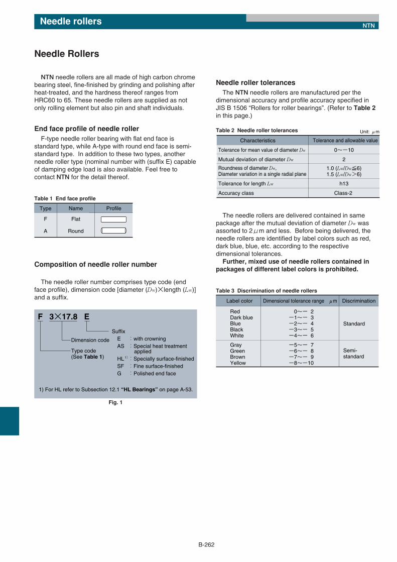
Composition of needle roller number
The needle roller number comprises type code (endface profile), dimension code [diameter (Dw)×length (Lw)]and a suffix.
F 3×17.8 E
Type code (See Table 1)
Dimension code
Suffix E :with crowning AS :Special heat treatment applied HL :Specially surface-finished SF :Fine surface-finished G :Polished end face
1)
1) For HL refer to Subsection 12.1 “HL Bearings” on page A-53.
Fig. 1
*13/構成部品/E_*13/構成部品/E 11/05/25 13:28 ページ 262
B-263
Needle rollers NTN
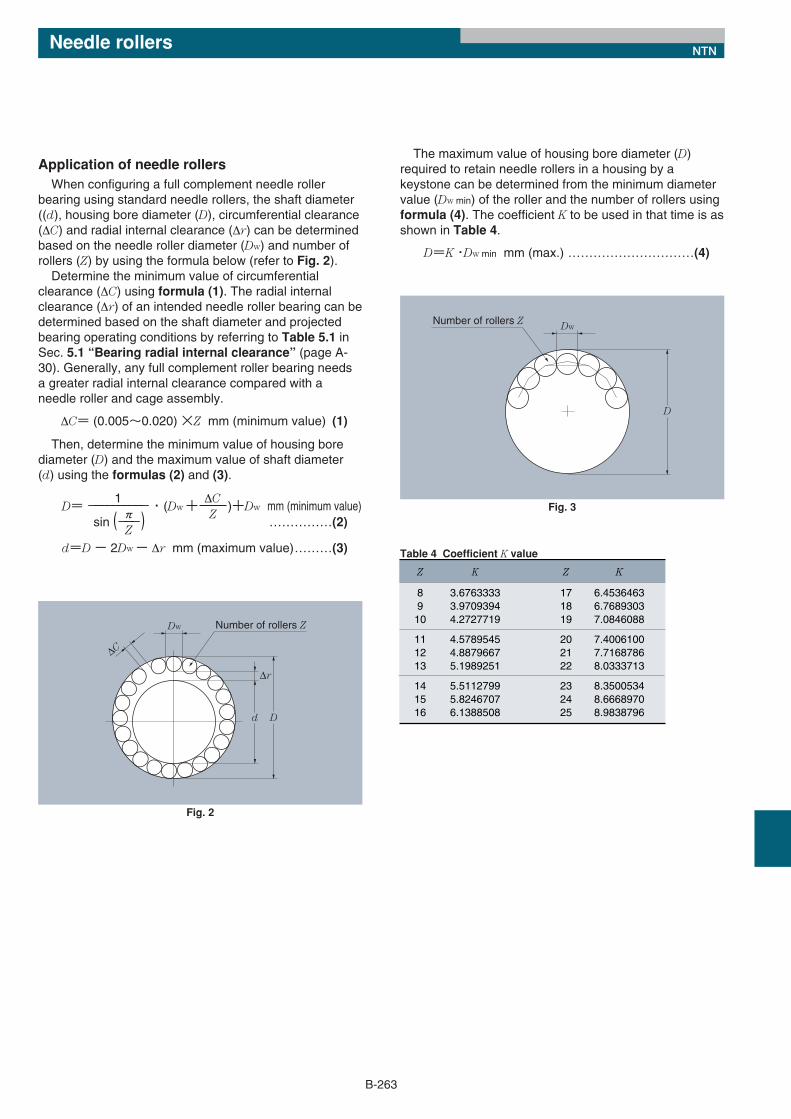
Application of needle rollers When configuring a full complement needle roller
bearing using standard needle rollers, the shaft diameter((d), housing bore diameter (D), circumferential clearance(ΔC) and radial internal clearance (Δr) can be determinedbased on the needle roller diameter (Dw) and number ofrollers (Z) by using the formula below (refer to Fig. 2).Determine the minimum value of circumferential
clearance (ΔC) using formula (1). The radial internalclearance (Δr) of an intended needle roller bearing can bedetermined based on the shaft diameter and projectedbearing operating conditions by referring to Table 5.1 inSec. 5.1 “Bearing radial internal clearance” (page A-30). Generally, any full complement roller bearing needsa greater radial internal clearance compared with aneedle roller and cage assembly.
ΔC= (0.005〜0.020) ×Z mm (minimum value) (1)
Then, determine the minimum value of housing borediameter (D) and the maximum value of shaft diameter(d) using the formulas (2) and (3).
1 ΔCD= −−−−−−−−−− ・ (Dw +−−−−)+Dw mm (minimum value)
π Zsin (−−−) ……………(2)
Z
d=D − 2Dw − Δr mm (maximum value)………(3) Table 4 Coefficient K value
8 9 10
11 12 13
14 15 16
Z
3.6763333 3.9709394 4.2727719
4.5789545 4.8879667 5.1989251
5.5112799 5.8246707 6.1388508
K
17 18 19
20 21 22
23 24 25
Z
6.4536463 6.7689303 7.0846088
7.4006100 7.7168786 8.0333713
8.3500534 8.6668970 8.9838796
K
Dw Number of rollers Z
∆r
∆C
d D
Fig. 2
Dw
D
Number of rollers Z
Fig. 3
The maximum value of housing bore diameter (D)required to retain needle rollers in a housing by akeystone can be determined from the minimum diametervalue (Dw min) of the roller and the number of rollers usingformula (4). The coefficient K to be used in that time is asshown in Table 4.
D=K ・Dw min mm (max.) …………………………(4)
*13/構成部品/E_*13/構成部品/E 11/05/25 13:28 ページ 263
B-264
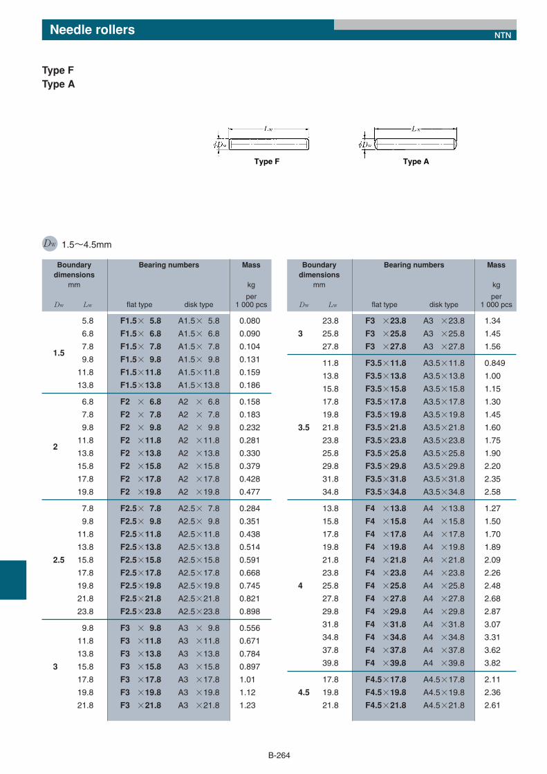
Type FType A
DW 1.5〜4.5mm
Type F Type A
Boundary Bearing numbers Massdimensions
mm kg
per Dw Lw flat type disk type 1 000 pcs
5.8 F1.5× 5.8 A1.5× 5.8 0.080
6.8 F1.5× 6.8 A1.5× 6.8 0.090
1.57.8 F1.5× 7.8 A1.5× 7.8 0.104
9.8 F1.5× 9.8 A1.5× 9.8 0.131
11.8 F1.5×11.8 A1.5×11.8 0.159
13.8 F1.5×13.8 A1.5×13.8 0.186
6.8 F2 × 6.8 A2 × 6.8 0.158
7.8 F2 × 7.8 A2 × 7.8 0.183
9.8 F2 × 9.8 A2 × 9.8 0.232
211.8 F2 ×11.8 A2 ×11.8 0.281
13.8 F2 ×13.8 A2 ×13.8 0.330
15.8 F2 ×15.8 A2 ×15.8 0.379
17.8 F2 ×17.8 A2 ×17.8 0.428
19.8 F2 ×19.8 A2 ×19.8 0.477
7.8 F2.5× 7.8 A2.5× 7.8 0.284
9.8 F2.5× 9.8 A2.5× 9.8 0.351
11.8 F2.5×11.8 A2.5×11.8 0.438
13.8 F2.5×13.8 A2.5×13.8 0.514
2.5 15.8 F2.5×15.8 A2.5×15.8 0.591
17.8 F2.5×17.8 A2.5×17.8 0.668
19.8 F2.5×19.8 A2.5×19.8 0.745
21.8 F2.5×21.8 A2.5×21.8 0.821
23.8 F2.5×23.8 A2.5×23.8 0.898
9.8 F3 × 9.8 A3 × 9.8 0.556
11.8 F3 ×11.8 A3 ×11.8 0.671
13.8 F3 ×13.8 A3 ×13.8 0.784
3 15.8 F3 ×15.8 A3 ×15.8 0.897
17.8 F3 ×17.8 A3 ×17.8 1.01
19.8 F3 ×19.8 A3 ×19.8 1.12
21.8 F3 ×21.8 A3 ×21.8 1.23
Boundary Bearing numbers Massdimensions
mm kg
per Dw Lw flat type disk type 1 000 pcs
23.8 F3 ×23.8 A3 ×23.8 1.34
3 25.8 F3 ×25.8 A3 ×25.8 1.45
27.8 F3 ×27.8 A3 ×27.8 1.56
11.8 F3.5×11.8 A3.5×11.8 0.849
13.8 F3.5×13.8 A3.5×13.8 1.00
15.8 F3.5×15.8 A3.5×15.8 1.15
17.8 F3.5×17.8 A3.5×17.8 1.30
19.8 F3.5×19.8 A3.5×19.8 1.45
3.5 21.8 F3.5×21.8 A3.5×21.8 1.60
23.8 F3.5×23.8 A3.5×23.8 1.75
25.8 F3.5×25.8 A3.5×25.8 1.90
29.8 F3.5×29.8 A3.5×29.8 2.20
31.8 F3.5×31.8 A3.5×31.8 2.35
34.8 F3.5×34.8 A3.5×34.8 2.58
13.8 F4 ×13.8 A4 ×13.8 1.27
15.8 F4 ×15.8 A4 ×15.8 1.50
17.8 F4 ×17.8 A4 ×17.8 1.70
19.8 F4 ×19.8 A4 ×19.8 1.89
21.8 F4 ×21.8 A4 ×21.8 2.09
23.8 F4 ×23.8 A4 ×23.8 2.26
4 25.8 F4 ×25.8 A4 ×25.8 2.48
27.8 F4 ×27.8 A4 ×27.8 2.68
29.8 F4 ×29.8 A4 ×29.8 2.87
31.8 F4 ×31.8 A4 ×31.8 3.07
34.8 F4 ×34.8 A4 ×34.8 3.31
37.8 F4 ×37.8 A4 ×37.8 3.62
39.8 F4 ×39.8 A4 ×39.8 3.82
17.8 F4.5×17.8 A4.5×17.8 2.11
4.5 19.8 F4.5×19.8 A4.5×19.8 2.36
21.8 F4.5×21.8 A4.5×21.8 2.61
Needle rollers NTN
*13/構成部品/E_*13/構成部品/E 11/05/25 13:28 ページ 264
B-265
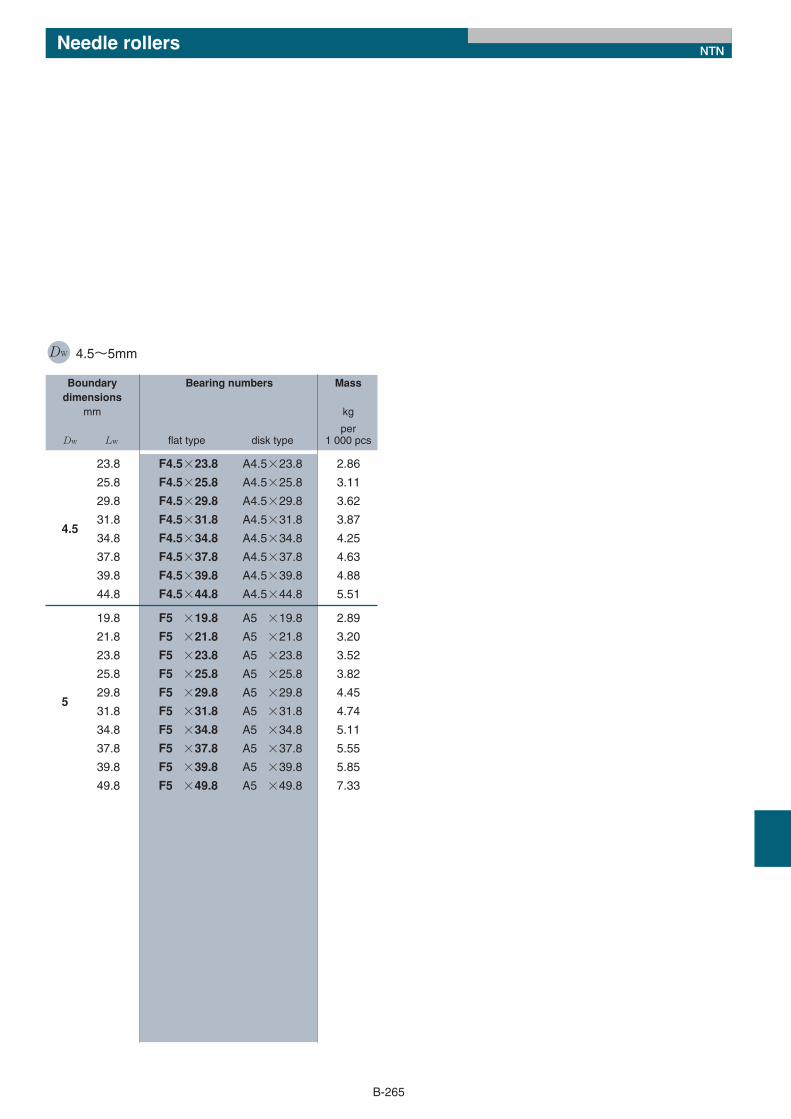
DW 4.5〜5mm
Boundary Bearing numbers Massdimensions
mm kg
perDw Lw flat type disk type 1 000 pcs
23.8 F4.5×23.8 A4.5×23.8 2.86
25.8 F4.5×25.8 A4.5×25.8 3.11
29.8 F4.5×29.8 A4.5×29.8 3.62
4.531.8 F4.5×31.8 A4.5×31.8 3.87
34.8 F4.5×34.8 A4.5×34.8 4.25
37.8 F4.5×37.8 A4.5×37.8 4.63
39.8 F4.5×39.8 A4.5×39.8 4.88
44.8 F4.5×44.8 A4.5×44.8 5.51
19.8 F5 ×19.8 A5 ×19.8 2.89
21.8 F5 ×21.8 A5 ×21.8 3.20
23.8 F5 ×23.8 A5 ×23.8 3.52
25.8 F5 ×25.8 A5 ×25.8 3.82
529.8 F5 ×29.8 A5 ×29.8 4.45
31.8 F5 ×31.8 A5 ×31.8 4.74
34.8 F5 ×34.8 A5 ×34.8 5.11
37.8 F5 ×37.8 A5 ×37.8 5.55
39.8 F5 ×39.8 A5 ×39.8 5.85
49.8 F5 ×49.8 A5 ×49.8 7.33
Needle rollers NTN
*13/構成部品/E_*13/構成部品/E 11/05/25 13:28 ページ 265
B-266
Snap rings NTN
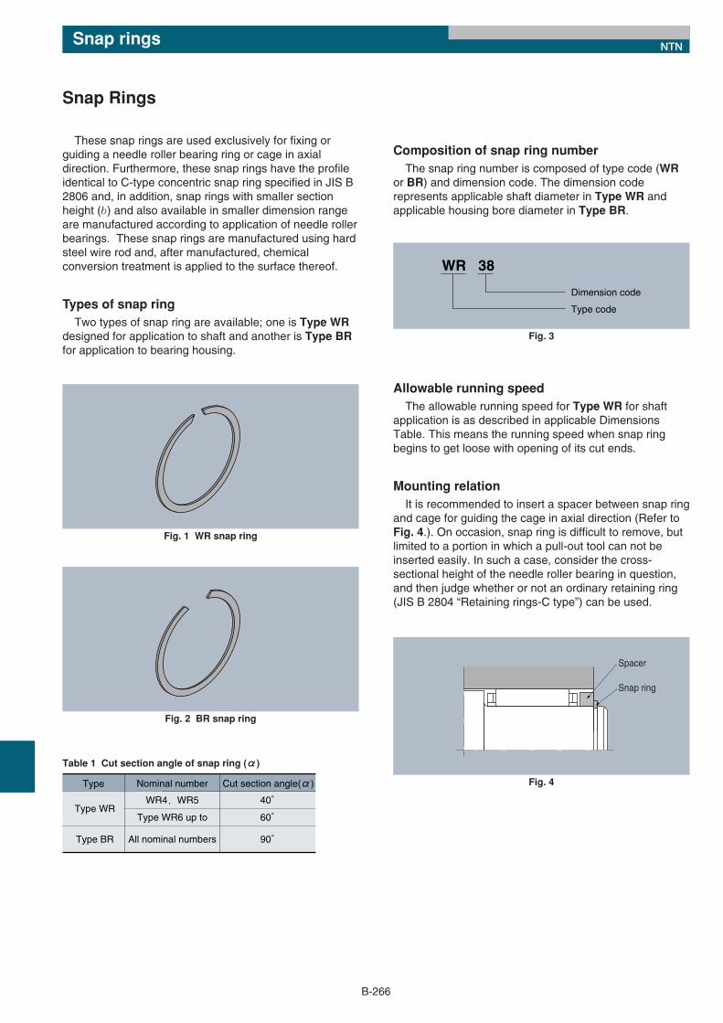
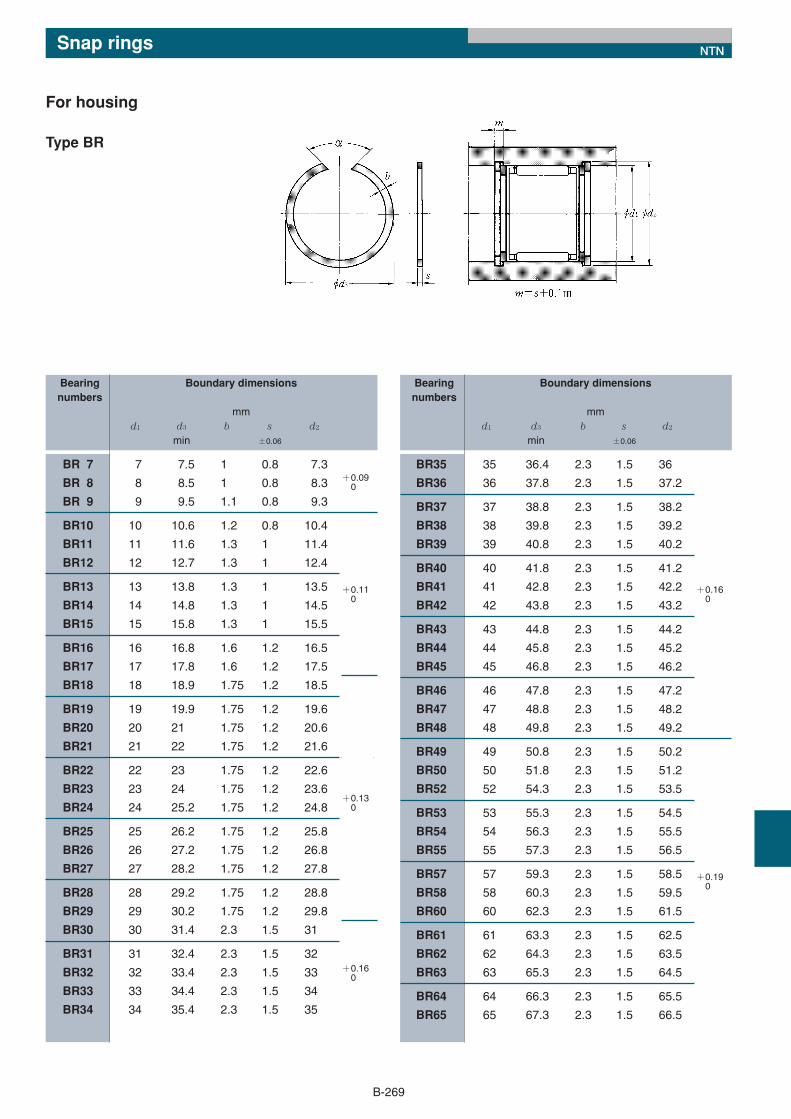
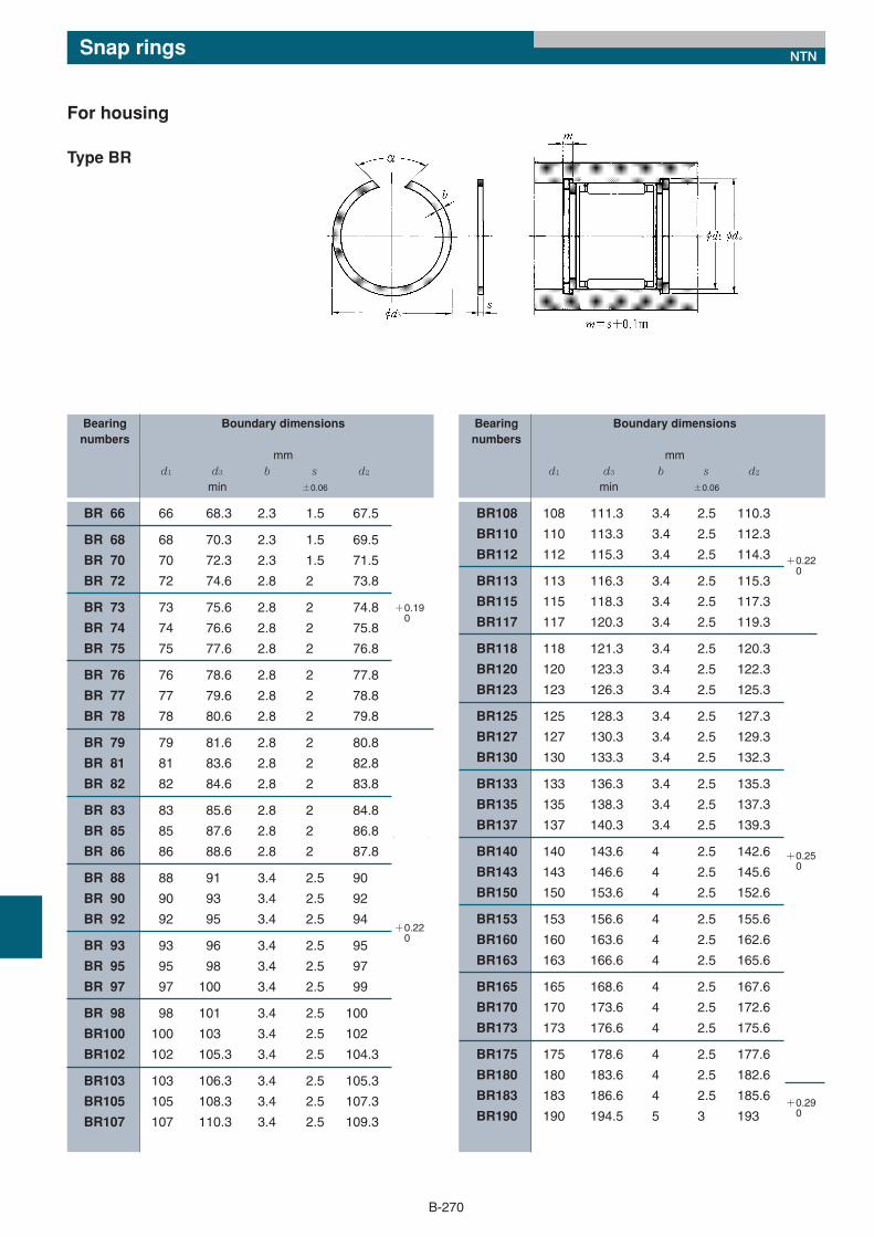
These snap rings are used exclusively for fixing orguiding a needle roller bearing ring or cage in axialdirection. Furthermore, these snap rings have the profileidentical to C-type concentric snap ring specified in JIS B2806 and, in addition, snap rings with smaller sectionheight (b) and also available in smaller dimension rangeare manufactured according to application of needle rollerbearings. These snap rings are manufactured using hardsteel wire rod and, after manufactured, chemicalconversion treatment is applied to the surface thereof.
Types of snap ring Two types of snap ring are available; one is Type WR
designed for application to shaft and another is Type BRfor application to bearing housing.
Snap Rings
Composition of snap ring numberThe snap ring number is composed of type code (WR
or BR) and dimension code. The dimension coderepresents applicable shaft diameter in Type WR andapplicable housing bore diameter in Type BR.
Allowable running speedThe allowable running speed for Type WR for shaft
application is as described in applicable DimensionsTable. This means the running speed when snap ringbegins to get loose with opening of its cut ends.
Mounting relation It is recommended to insert a spacer between snap ring
and cage for guiding the cage in axial direction (Refer toFig. 4.). On occasion, snap ring is difficult to remove, butlimited to a portion in which a pull-out tool can not beinserted easily. In such a case, consider the cross-sectional height of the needle roller bearing in question,and then judge whether or not an ordinary retaining ring(JIS B 2804 “Retaining rings-C type”) can be used.
Fig. 1 WR snap ring
Fig. 2 BR snap ring
WR 38
Type code
Dimension code
Fig. 3
Table 1 Cut section angle of snap ring (α)
Type Nominal number Cut section angle(α)
Type WR
Type BR
WR4,WR5
Type WR6 up to
All nominal numbers
40°
60°
90°
Spacer
Snap ring
Fig. 4
*13/構成部品/E_*13/構成部品/E 11/05/25 13:28 ページ 266
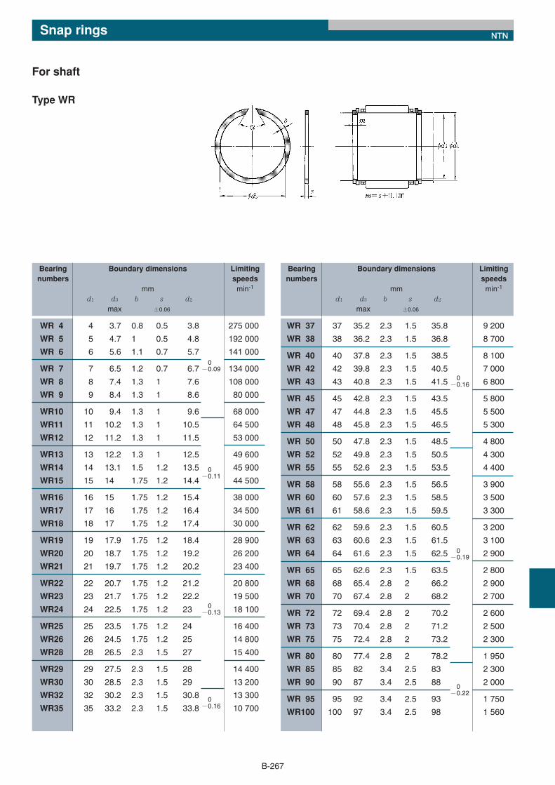
WR 4 4 3.7 0.8 0.5 3.8 275 000
WR 5 5 4.7 1 0.5 4.8 192 000
WR 6 6 5.6 1.1 0.7 5.7 141 000
WR 7 7 6.5 1.2 0.7 6.7 134 000
WR 8 8 7.4 1.3 1 7.6 108 000
WR 9 9 8.4 1.3 1 8.6 80 000
WR10 10 9.4 1.3 1 9.6 68 000
WR11 11 10.2 1.3 1 10.5 64 500
WR12 12 11.2 1.3 1 11.5 53 000
WR13 13 12.2 1.3 1 12.5 49 600
WR14 14 13.1 1.5 1.2 13.5 45 900
WR15 15 14 1.75 1.2 14.4 44 500
WR16 16 15 1.75 1.2 15.4 38 000
WR17 17 16 1.75 1.2 16.4 34 500
WR18 18 17 1.75 1.2 17.4 30 000
WR19 19 17.9 1.75 1.2 18.4 28 900
WR20 20 18.7 1.75 1.2 19.2 26 200
WR21 21 19.7 1.75 1.2 20.2 23 400
WR22 22 20.7 1.75 1.2 21.2 20 800
WR23 23 21.7 1.75 1.2 22.2 19 500
WR24 24 22.5 1.75 1.2 23 18 100
WR25 25 23.5 1.75 1.2 24 16 400
WR26 26 24.5 1.75 1.2 25 14 800
WR28 28 26.5 2.3 1.5 27 15 400
WR29 29 27.5 2.3 1.5 28 14 400
WR30 30 28.5 2.3 1.5 29 13 200
WR32 32 30.2 2.3 1.5 30.8 13 300
WR35 35 33.2 2.3 1.5 33.8 10 700
WR 37 37 35.2 2.3 1.5 35.8 9 200
WR 38 38 36.2 2.3 1.5 36.8 8 700
WR 40 40 37.8 2.3 1.5 38.5 8 100
WR 42 42 39.8 2.3 1.5 40.5 7 000
WR 43 43 40.8 2.3 1.5 41.5 6 800
WR 45 45 42.8 2.3 1.5 43.5 5 800
WR 47 47 44.8 2.3 1.5 45.5 5 500
WR 48 48 45.8 2.3 1.5 46.5 5 300
WR 50 50 47.8 2.3 1.5 48.5 4 800
WR 52 52 49.8 2.3 1.5 50.5 4 300
WR 55 55 52.6 2.3 1.5 53.5 4 400
WR 58 58 55.6 2.3 1.5 56.5 3 900
WR 60 60 57.6 2.3 1.5 58.5 3 500
WR 61 61 58.6 2.3 1.5 59.5 3 300
WR 62 62 59.6 2.3 1.5 60.5 3 200
WR 63 63 60.6 2.3 1.5 61.5 3 100
WR 64 64 61.6 2.3 1.5 62.5 2 900
WR 65 65 62.6 2.3 1.5 63.5 2 800
WR 68 68 65.4 2.8 2 66.2 2 900
WR 70 70 67.4 2.8 2 68.2 2 700
WR 72 72 69.4 2.8 2 70.2 2 600
WR 73 73 70.4 2.8 2 71.2 2 500
WR 75 75 72.4 2.8 2 73.2 2 300
WR 80 80 77.4 2.8 2 78.2 1 950
WR 85 85 82 3.4 2.5 83 2 300
WR 90 90 87 3.4 2.5 88 2 000
WR 95 95 92 3.4 2.5 93 1 750
WR100 100 97 3.4 2.5 98 1 560
0−0.19
0−0.16
B-267
Bearing Boundary dimensions Limitingnumbers speeds
mm min-1
d1 d3 b s d2
max ±0.06
Bearing Boundary dimensions Limitingnumbers speeds
mm min-1
d1 d3 b s d2
max ±0.06
For shaft
Type WR
Snap rings NTN
0−0.22
0−0.09
0−0.11
0−0.13
0−0.16
*13/構成部品/E_*13/構成部品/E 11/05/25 13:28 ページ 267
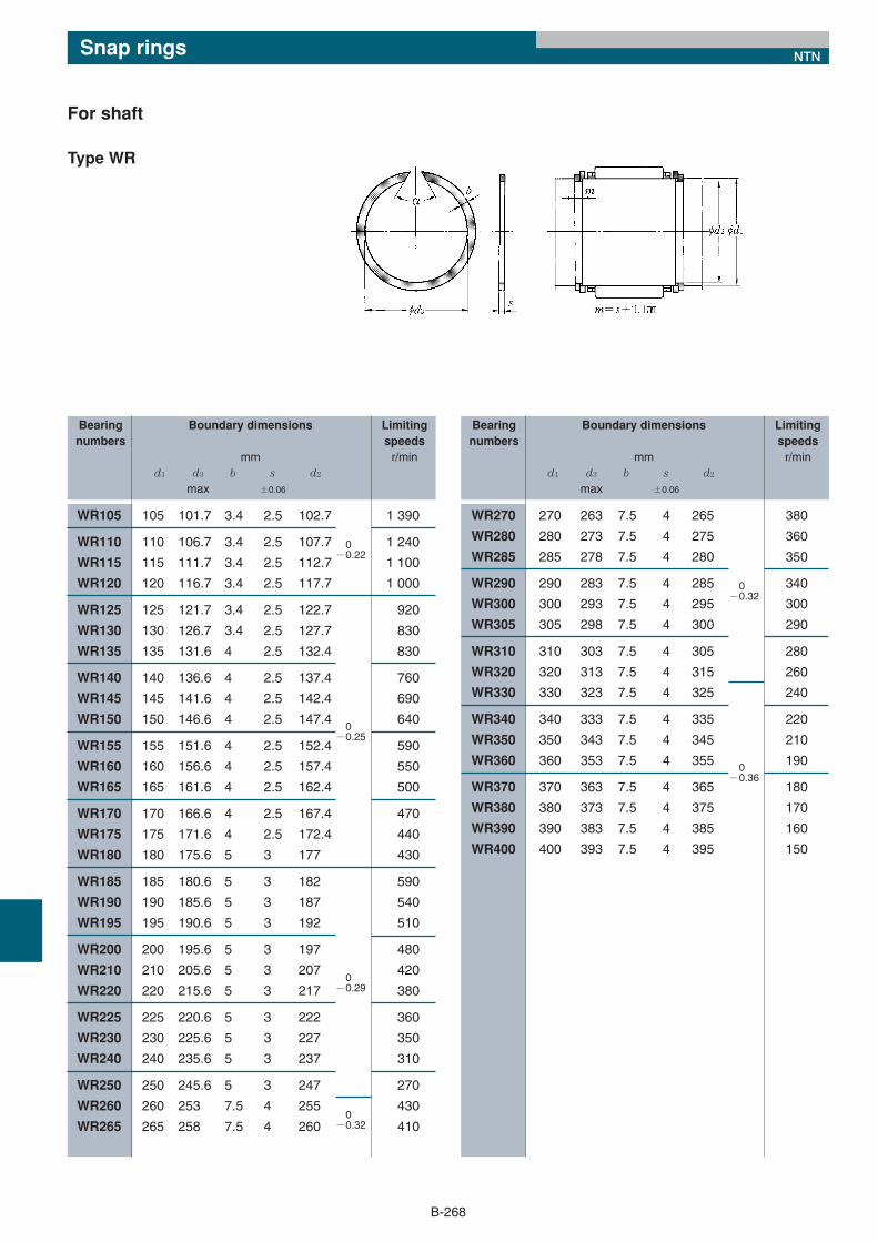
WR270 270 263 7.5 4 265 380
WR280 280 273 7.5 4 275 360
WR285 285 278 7.5 4 280 350
WR290 290 283 7.5 4 285 340
WR300 300 293 7.5 4 295 300
WR305 305 298 7.5 4 300 290
WR310 310 303 7.5 4 305 280
WR320 320 313 7.5 4 315 260
WR330 330 323 7.5 4 325 240
WR340 340 333 7.5 4 335 220
WR350 350 343 7.5 4 345 210
WR360 360 353 7.5 4 355 190
WR370 370 363 7.5 4 365 180
WR380 380 373 7.5 4 375 170
WR390 390 383 7.5 4 385 160
WR400 400 393 7.5 4 395 150
WR105 105 101.7 3.4 2.5 102.7 1 390
WR110 110 106.7 3.4 2.5 107.7 1 240
WR115 115 111.7 3.4 2.5 112.7 1 100
WR120 120 116.7 3.4 2.5 117.7 1 000
WR125 125 121.7 3.4 2.5 122.7 920
WR130 130 126.7 3.4 2.5 127.7 830
WR135 135 131.6 4 2.5 132.4 830
WR140 140 136.6 4 2.5 137.4 760
WR145 145 141.6 4 2.5 142.4 690
WR150 150 146.6 4 2.5 147.4 640
WR155 155 151.6 4 2.5 152.4 590
WR160 160 156.6 4 2.5 157.4 550
WR165 165 161.6 4 2.5 162.4 500
WR170 170 166.6 4 2.5 167.4 470
WR175 175 171.6 4 2.5 172.4 440
WR180 180 175.6 5 3 177 430
WR185 185 180.6 5 3 182 590
WR190 190 185.6 5 3 187 540
WR195 195 190.6 5 3 192 510
WR200 200 195.6 5 3 197 480
WR210 210 205.6 5 3 207 420
WR220 220 215.6 5 3 217 380
WR225 225 220.6 5 3 222 360
WR230 230 225.6 5 3 227 350
WR240 240 235.6 5 3 237 310
WR250 250 245.6 5 3 247 270
WR260 260 253 7.5 4 255 430
WR265 265 258 7.5 4 260 410
Bearing Boundary dimensions Limitingnumbers speeds
mm r/mind1 d3 b s d2
max ±0.06
B-268
Bearing Boundary dimensions Limitingnumbers speeds
mm r/mind1 d3 b s d2
max ±0.06
For shaft
Type WR
Snap rings NTN
0−0.22
0−0.25
0−0.32
0−0.36
0−0.32
0−0.29
*13/構成部品/E_*13/構成部品/E 11/05/25 13:28 ページ 268
BR 7 7 7.5 1 0.8 7.3
BR 8 8 8.5 1 0.8 8.3
BR 9 9 9.5 1.1 0.8 9.3
BR10 10 10.6 1.2 0.8 10.4
BR11 11 11.6 1.3 1 11.4
BR12 12 12.7 1.3 1 12.4
BR13 13 13.8 1.3 1 13.5
BR14 14 14.8 1.3 1 14.5
BR15 15 15.8 1.3 1 15.5
BR16 16 16.8 1.6 1.2 16.5
BR17 17 17.8 1.6 1.2 17.5
BR18 18 18.9 1.75 1.2 18.5
BR19 19 19.9 1.75 1.2 19.6
BR20 20 21 1.75 1.2 20.6
BR21 21 22 1.75 1.2 21.6
BR22 22 23 1.75 1.2 22.6
BR23 23 24 1.75 1.2 23.6
BR24 24 25.2 1.75 1.2 24.8
BR25 25 26.2 1.75 1.2 25.8
BR26 26 27.2 1.75 1.2 26.8
BR27 27 28.2 1.75 1.2 27.8
BR28 28 29.2 1.75 1.2 28.8
BR29 29 30.2 1.75 1.2 29.8
BR30 30 31.4 2.3 1.5 31
BR31 31 32.4 2.3 1.5 32
BR32 32 33.4 2.3 1.5 33
BR33 33 34.4 2.3 1.5 34
BR34 34 35.4 2.3 1.5 35
BR35 35 36.4 2.3 1.5 36
BR36 36 37.8 2.3 1.5 37.2
BR37 37 38.8 2.3 1.5 38.2
BR38 38 39.8 2.3 1.5 39.2
BR39 39 40.8 2.3 1.5 40.2
BR40 40 41.8 2.3 1.5 41.2
BR41 41 42.8 2.3 1.5 42.2
BR42 42 43.8 2.3 1.5 43.2
BR43 43 44.8 2.3 1.5 44.2
BR44 44 45.8 2.3 1.5 45.2
BR45 45 46.8 2.3 1.5 46.2
BR46 46 47.8 2.3 1.5 47.2
BR47 47 48.8 2.3 1.5 48.2
BR48 48 49.8 2.3 1.5 49.2
BR49 49 50.8 2.3 1.5 50.2
BR50 50 51.8 2.3 1.5 51.2
BR52 52 54.3 2.3 1.5 53.5
BR53 53 55.3 2.3 1.5 54.5
BR54 54 56.3 2.3 1.5 55.5
BR55 55 57.3 2.3 1.5 56.5
BR57 57 59.3 2.3 1.5 58.5
BR58 58 60.3 2.3 1.5 59.5
BR60 60 62.3 2.3 1.5 61.5
BR61 61 63.3 2.3 1.5 62.5
BR62 62 64.3 2.3 1.5 63.5
BR63 63 65.3 2.3 1.5 64.5
BR64 64 66.3 2.3 1.5 65.5
BR65 65 67.3 2.3 1.5 66.5
Snap rings NTN
B-269
Bearing Boundary dimensionsnumbers
mmd1 d3 b s d2
min ±0.06
For housing
Type BR
Bearing Boundary dimensionsnumbers
mmd1 d3 b s d2
min ±0.06
+0.090
+0.110
+0.160
+0.130
+0.160
+0.190
*13/構成部品/E_*13/構成部品/E 11/05/25 13:28 ページ 269
BR 66 66 68.3 2.3 1.5 67.5
BR 68 68 70.3 2.3 1.5 69.5
BR 70 70 72.3 2.3 1.5 71.5
BR 72 72 74.6 2.8 2 73.8
BR 73 73 75.6 2.8 2 74.8
BR 74 74 76.6 2.8 2 75.8
BR 75 75 77.6 2.8 2 76.8
BR 76 76 78.6 2.8 2 77.8
BR 77 77 79.6 2.8 2 78.8
BR 78 78 80.6 2.8 2 79.8
BR 79 79 81.6 2.8 2 80.8
BR 81 81 83.6 2.8 2 82.8
BR 82 82 84.6 2.8 2 83.8
BR 83 83 85.6 2.8 2 84.8
BR 85 85 87.6 2.8 2 86.8
BR 86 86 88.6 2.8 2 87.8
BR 88 88 91 3.4 2.5 90
BR 90 90 93 3.4 2.5 92
BR 92 92 95 3.4 2.5 94
BR 93 93 96 3.4 2.5 95
BR 95 95 98 3.4 2.5 97
BR 97 97 100 3.4 2.5 99
BR 98 98 101 3.4 2.5 100
BR100 100 103 3.4 2.5 102
BR102 102 105.3 3.4 2.5 104.3
BR103 103 106.3 3.4 2.5 105.3
BR105 105 108.3 3.4 2.5 107.3
BR107 107 110.3 3.4 2.5 109.3
BR108 108 111.3 3.4 2.5 110.3
BR110 110 113.3 3.4 2.5 112.3
BR112 112 115.3 3.4 2.5 114.3
BR113 113 116.3 3.4 2.5 115.3
BR115 115 118.3 3.4 2.5 117.3
BR117 117 120.3 3.4 2.5 119.3
BR118 118 121.3 3.4 2.5 120.3
BR120 120 123.3 3.4 2.5 122.3
BR123 123 126.3 3.4 2.5 125.3
BR125 125 128.3 3.4 2.5 127.3
BR127 127 130.3 3.4 2.5 129.3
BR130 130 133.3 3.4 2.5 132.3
BR133 133 136.3 3.4 2.5 135.3
BR135 135 138.3 3.4 2.5 137.3
BR137 137 140.3 3.4 2.5 139.3
BR140 140 143.6 4 2.5 142.6
BR143 143 146.6 4 2.5 145.6
BR150 150 153.6 4 2.5 152.6
BR153 153 156.6 4 2.5 155.6
BR160 160 163.6 4 2.5 162.6
BR163 163 166.6 4 2.5 165.6
BR165 165 168.6 4 2.5 167.6
BR170 170 173.6 4 2.5 172.6
BR173 173 176.6 4 2.5 175.6
BR175 175 178.6 4 2.5 177.6
BR180 180 183.6 4 2.5 182.6
BR183 183 186.6 4 2.5 185.6
BR190 190 194.5 5 3 193
B-270
Snap rings NTN
Bearing Boundary dimensionsnumbers
mmd1 d3 b s d2
min ±0.06
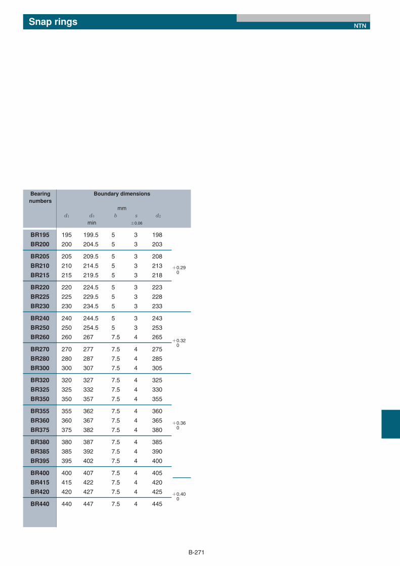
For housing
Type BR
Bearing Boundary dimensionsnumbers
mmd1 d3 b s d2
min ±0.06
+0.220
+0.190
+0.220
+0.250
+0.290
*13/構成部品/E_*13/構成部品/E 11/05/25 13:28 ページ 270
BR195 195 199.5 5 3 198
BR200 200 204.5 5 3 203
BR205 205 209.5 5 3 208
BR210 210 214.5 5 3 213
BR215 215 219.5 5 3 218
BR220 220 224.5 5 3 223
BR225 225 229.5 5 3 228
BR230 230 234.5 5 3 233
BR240 240 244.5 5 3 243
BR250 250 254.5 5 3 253
BR260 260 267 7.5 4 265
BR270 270 277 7.5 4 275
BR280 280 287 7.5 4 285
BR300 300 307 7.5 4 305
BR320 320 327 7.5 4 325
BR325 325 332 7.5 4 330
BR350 350 357 7.5 4 355
BR355 355 362 7.5 4 360
BR360 360 367 7.5 4 365
BR375 375 382 7.5 4 380
BR380 380 387 7.5 4 385
BR385 385 392 7.5 4 390
BR395 395 402 7.5 4 400
BR400 400 407 7.5 4 405
BR415 415 422 7.5 4 420
BR420 420 427 7.5 4 425
BR440 440 447 7.5 4 445
B-271
Snap rings NTN
Bearing Boundary dimensionsnumbers
mmd1 d3 b s d2
min ±0.06
+0.290
+0.320
+0.360
+0.400
*13/構成部品/E_*13/構成部品/E 11/05/25 13:28 ページ 271
B-272
Seals NTN
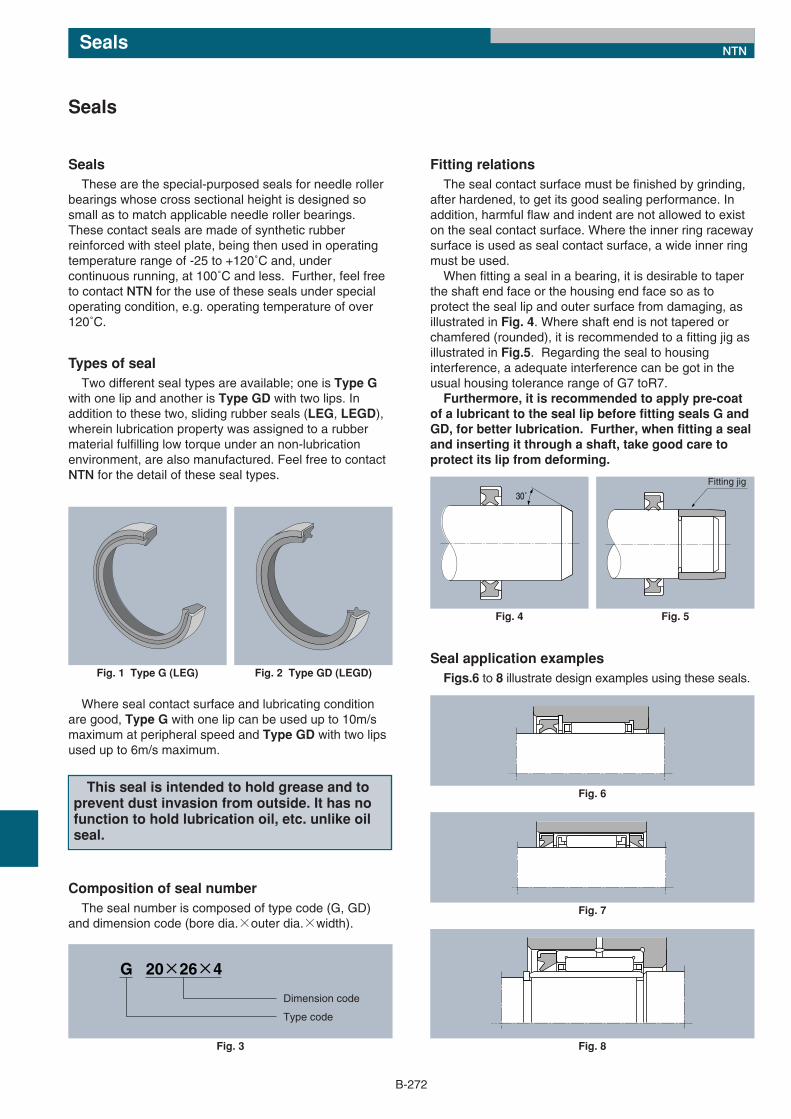
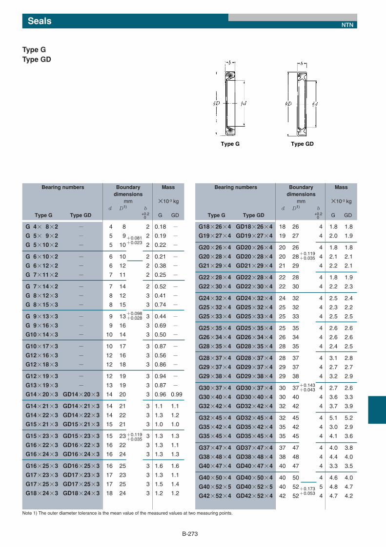
Seals These are the special-purposed seals for needle roller
bearings whose cross sectional height is designed sosmall as to match applicable needle roller bearings.These contact seals are made of synthetic rubberreinforced with steel plate, being then used in operatingtemperature range of -25 to +120˚C and, undercontinuous running, at 100˚C and less. Further, feel freeto contact NTN for the use of these seals under specialoperating condition, e.g. operating temperature of over120˚C.
Types of sealTwo different seal types are available; one is Type G
with one lip and another is Type GD with two lips. Inaddition to these two, sliding rubber seals (LEG, LEGD),wherein lubrication property was assigned to a rubbermaterial fulfilling low torque under an non-lubricationenvironment, are also manufactured. Feel free to contactNTN for the detail of these seal types.
Seals
30˚
Fig. 4
Fitting jig
Fig. 5
Fig. 6
Fig. 7
Fig. 8
G 20×26×4
Type code
Dimension code
Fig. 3
Fig. 1 Type G (LEG) Fig. 2 Type GD (LEGD)
Where seal contact surface and lubricating conditionare good, Type G with one lip can be used up to 10m/smaximum at peripheral speed and Type GD with two lipsused up to 6m/s maximum.
This seal is intended to hold grease and toprevent dust invasion from outside. It has nofunction to hold lubrication oil, etc. unlike oilseal.
Composition of seal numberThe seal number is composed of type code (G, GD)
and dimension code (bore dia.×outer dia.×width).
Fitting relationsThe seal contact surface must be finished by grinding,
after hardened, to get its good sealing performance. Inaddition, harmful flaw and indent are not allowed to existon the seal contact surface. Where the inner ring racewaysurface is used as seal contact surface, a wide inner ringmust be used. When fitting a seal in a bearing, it is desirable to taper
the shaft end face or the housing end face so as toprotect the seal lip and outer surface from damaging, asillustrated in Fig. 4. Where shaft end is not tapered orchamfered (rounded), it is recommended to a fitting jig asillustrated in Fig.5. Regarding the seal to housinginterference, a adequate interference can be got in theusual housing tolerance range of G7 toR7. Furthermore, it is recommended to apply pre-coat
of a lubricant to the seal lip before fitting seals G andGD, for better lubrication. Further, when fitting a sealand inserting it through a shaft, take good care toprotect its lip from deforming.
Seal application examples Figs.6 to 8 illustrate design examples using these seals.
*13/構成部品/E_*13/構成部品/E 11/05/25 13:28 ページ 272
G 4× 8×2 − 4 8 2 0.18 −G 5× 9×2 − 5 9 2 0.19 −G 5×10×2 − 5 10 2 0.22 −
G 6×10×2 − 6 10 2 0.21 −G 6×12×2 − 6 12 2 0.38 −G 7×11×2 − 7 11 2 0.25 −
G 7×14×2 − 7 14 2 0.52 −G 8×12×3 − 8 12 3 0.41 −G 8×15×3 − 8 15 3 0.74 −
G 9×13×3 − 9 13 3 0.44 −G 9×16×3 − 9 16 3 0.69 −G10×14×3 − 10 14 3 0.50 −
G10×17×3 − 10 17 3 0.87 −G12×16×3 − 12 16 3 0.56 −G12×18×3 − 12 18 3 0.86 −
G12×19×3 − 12 19 3 0.94 −G13×19×3 − 13 19 3 0.87 −G14×20×3 GD14×20×3 14 20 3 0.96 0.99
G14×21×3 GD14×21×3 14 21 3 1.1 1.1
G14×22×3 GD14×22×3 14 22 3 1.3 1.2
G15×21×3 GD15×21×3 15 21 3 1.0 1.0
G15×23×3 GD15×23×3 15 23 3 1.3 1.3
G16×22×3 GD16×22×3 16 22 3 1.3 1.1
G16×24×3 GD16×24×3 16 24 3 1.3 1.3
G16×25×3 GD16×25×3 16 25 3 1.6 1.6
G17×23×3 GD17×23×3 17 23 3 1.3 1.1
G17×25×3 GD17×25×3 17 25 3 1.5 1.4
G18×24×3 GD18×24×3 18 24 3 1.2 1.2
G18×26×4 GD18×26×4 18 26 4 1.8 1.8
G19×27×4 GD19×27×4 19 27 4 2.0 1.9
G20×26×4 GD20×26×4 20 26 4 1.8 1.8
G20×28×4 GD20×28×4 20 28 4 2.1 2.1
G21×29×4 GD21×29×4 21 29 4 2.2 2.1
G22×28×4 GD22×28×4 22 28 4 1.8 1.9
G22×30×4 GD22×30×4 22 30 4 2.2 2.3
G24×32×4 GD24×32×4 24 32 4 2.5 2.4
G25×32×4 GD25×32×4 25 32 4 2.3 2.2
G25×33×4 GD25×33×4 25 33 4 2.5 2.5
G25×35×4 GD25×35×4 25 35 4 2.6 2.6
G26×34×4 GD26×34×4 26 34 4 2.6 2.6
G28×35×4 GD28×35×4 28 35 4 2.4 2.5
G28×37×4 GD28×37×4 28 37 4 3.1 2.8
G29×37×4 GD29×37×4 29 37 4 2.7 2.7
G29×38×4 GD29×38×4 29 38 4 3.2 2.9
G30×37×4 GD30×37×4 30 37 4 2.7 2.6
G30×40×4 GD30×40×4 30 40 4 3.6 3.3
G32×42×4 GD32×42×4 32 42 4 3.7 3.9
G32×45×4 GD32×45×4 32 45 4 5.1 5.2
G35×42×4 GD35×42×4 35 42 4 3.0 2.9
G35×45×4 GD35×45×4 35 45 4 4.1 3.6
G37×47×4 GD37×47×4 37 47 4 4.0 3.8
G38×48×4 GD38×48×4 38 48 4 4.4 4.0
G40×47×4 GD40×47×4 40 47 4 3.3 3.5
G40×50×4 GD40×50×4 40 50 4 4.6 4.0
G40×52×5 GD40×52×5 40 52 5 4.8 4.7
G42×52×4 GD42×52×4 42 52 4 4.7 4.2
B-273
Note 1) The outer diameter tolerance is the mean value of the measured values at two measuring points.
Type G Type GD
Bearing numbers Boundary Massdimensions
mm ×10-3 kgd D1) b
Type G Type GD G GD
Type GType GD
+0.20
Bearing numbers Boundary Massdimensions
mm ×10-3 kgd D1) b
Type G Type GD G GD+0.20
+0.173+0.053
+0.081+0.023
+0.119+0.035
+0.098+0.028
+0.119+0.035
+0.143+0.043
Seals NTN
*13/構成部品/E_*13/構成部品/E 11/05/25 13:28 ページ 273
G43×53×4 GD43×53×4 43 53 4 4.8 4.3
G45×52×4 GD45×52×4 45 52 4 3.8 3.8
G45×55×4 GD45×55×4 45 55 4 5.2 5.5
G50×58×4 GD50×58×4 50 58 4 4.5 5.2
G50×62×5 GD50×62×5 50 62 5 10.4 10
B-274
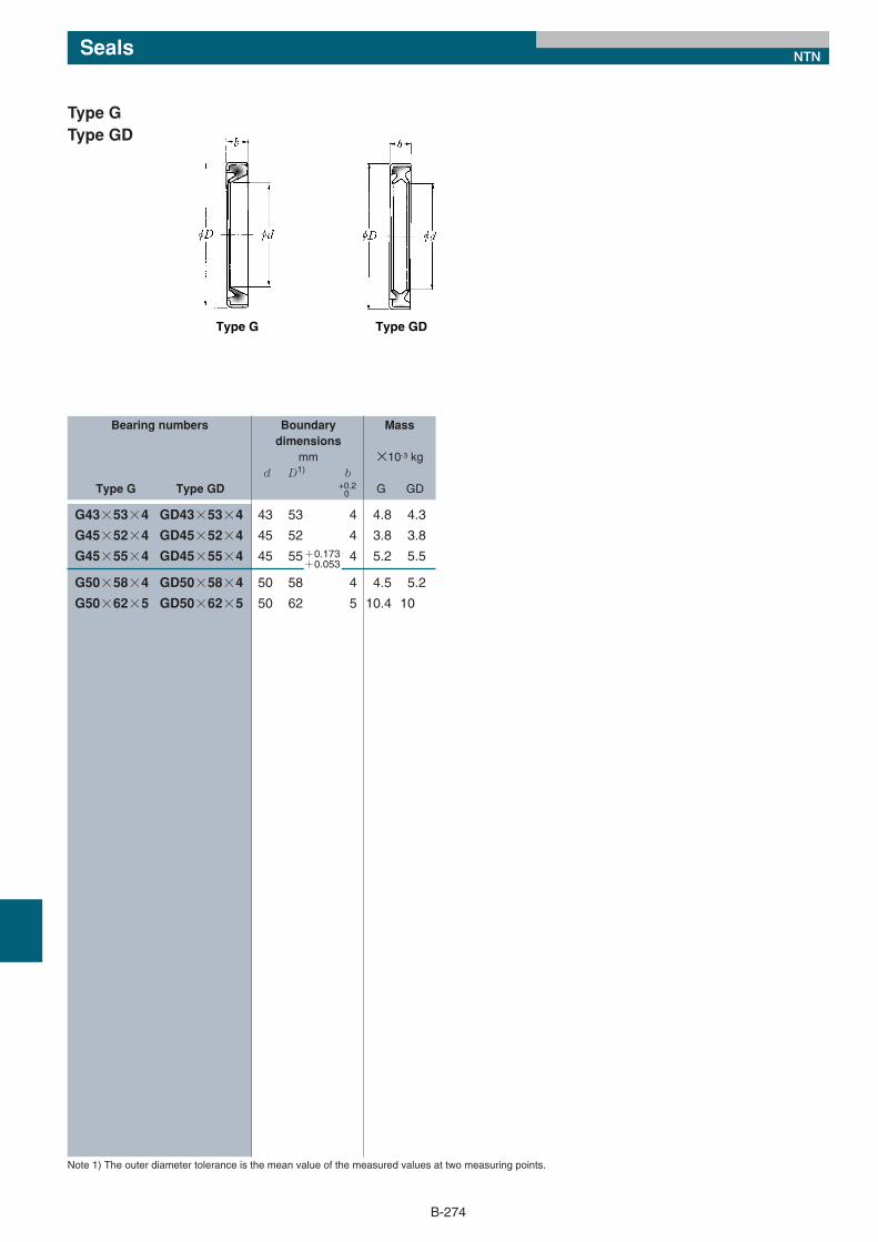
Note 1) The outer diameter tolerance is the mean value of the measured values at two measuring points.
Bearing numbers Boundary Massdimensions
mm ×10-3 kgd D1) b
Type G Type GD G GD
Type GType GD
+0.20
Seals NTN
Type G Type GD
+0.173+0.053
*13/構成部品/E_*13/構成部品/E 11/05/25 13:28 ページ 274