Embed Size (px)
Citation preview
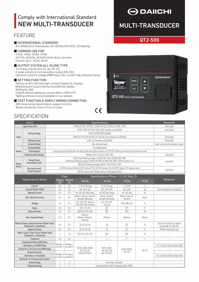
Comply with International Standard NEW MULTI-TRANSDUCER MULTI-TRANSDUCER
Items Specifi cations RemarksInput Phase Wire 3P4W (2VT3CT, 3VT3CT) , 3P3W (2VT2CT, 2VT3CT), 1P3W, 1P2W Selectable
InputRating Voltage
3P3W, 1P2W: AC110V, 220V, 440V common use 50/60Hz Selectable3P3W: AC100-200V 50/60Hz -
3P4W: AC110/√3V, AC220/√3V, AC440/√3V common use 50/60Hz SelectableRating Current AC5A, 1A common use 50/60Hz SelectableExternal Reset Max. demand reset Input rating same as power supply
OutputAnalog Output 10-analog output -Pulse Output 2-pulse output by Photo Mos-Fet Relay, Normally Open contact, AC, DC125V, 70mA (resistance load, inductive load) -
Communication Output Modbus RTU, Protocol A (RS-485) Selectable
PowerSupply
Range PowerConsumption (VA)
AC80-264V (Rating voltage: AC100/110V 15VA, AC200/220V 18VADC80-264V (Rating voltage: DC100/110V 9W, DC200/220V 10W) AC/DC common use Specifi ed
DC20-57V (Rating voltage: DC24V, 11W, DC48V 12W)
Starting Current(Time Constant)
AC110V: below 5.5VA, AC220V: below 10.9A, DC110V: below 3.9A, DC220V: below 7.7A (approx.5ms)Specifi ed
DC24V: below 6.3A, DC48V: below 12.6A (approx.8ms)
Measurement ItemsClass Specifi cations (Phase: 1,2,3,N; Total: ∑)
RemarksRating 5A
Rating 1A 3P4W 3P3W 1P3W 1P2W
Current 0.2 0.5 I1, I2, I3, IN, Iavg I1, I2, I3, Iavg I1, I3, IN I -Current (Power Flow) 0.2 0.5 Ipf1, Ipf2, Ipf3 Ipf1, Ipf2, Ipf3 Ipf1, Ipf3 Ipf Polarity depends on power ∑P
Demand Current 0.2 0.5 Id1, Id2, Id3, IdN, Idavg Id1, Id2, Id3, Idavg Id1, Id3, IdN Id -
Max. Demand Current 0.2 0.5 Idmax1, Idmax2, Idmax3,IdmaxN, Idmaxavg
Idmax1, Idmax2,Idmax3, Idmaxavg
Idmax1, Idmax3,IdmaxN Idmax -
Voltage 0.2 0.2 U12, U23, U31, ULLavgU1N, U2N, U3N, ULNavg
U12, U23, U31,ULLavg U1N, U3N, U13 U -
Power 0.3 0.5 ∑P, P1, P2, P3 ∑P ∑P P -Demand Power 0.3 0.5 ∑Pd, Pd1, Pd2, Pd3 ∑Pd ∑Pd Pd -
Max. Demand Power 0.3 0.5∑Pdmax,
Pdmax1, Pdmax2, Pdmax3
∑Pdmax ∑Pdmax Pdmax -
Reactive Power, Reactive Power (Power Flow)2 Quadrants, 4 Quadrants 0.3 0.5 ∑Q, Q1, Q2, Q3 ∑Q ∑Q Q Select calculation as below
Q=UIsinφ, Q=√(S2-P2)Apparent Power 0.3 0.5 ∑S, S1, S2, S3 ∑S ∑S S 3P3W is balanced load.
Power Factor, Power Facotr (Power Flow)2 Quadrants, 4 Quadrants 1 1.5 ∑PF, PF1, PF2, PF3 ∑PF ∑PF PF -
Frequency 0.2 0.2 f f f f -Fundamental Wave RMS Value
Voltage: 1Current: 1
Voltage: 1Current: 2 HU1N, HU2N, HU3N,
HI1, HI2, HI3(HU2N: 3VT3CT)
HU12, HU23,HI1, HI2, HI3
(HI2: 2VT3CT)
HU1N, HU3N,HI1, HI3 HU, HI
-Harmonics n-th RMS Value n=3…15 times (odd number only)
Harmonics 5-th Conversion RMS Value -Distortion Factor
Voltage: 2Current: 2
Voltage: 2Current: 2.5
-Harmonics n-th Content n=3…15 times (odd number only)
Harmonics 5-th Conversion Content -Actice Energy 1 2 Incoming / Outgoing -
Reactive Energy 2 2 Incoming (LAG, LEAD) / Outgoing (LAG, LEAD) -
SPECIFICATION
■ INTERNATIONAL STANDARD- IEC 60688:2012 (Transducer), IEC 62053:2003 (Wh), CE Marking
■ COMMON USE FOR- 1P2W, 1P3W, 3P3W, 3P4W - AC110V, AC220V, AC440V (440V direct connect)- Current input: AC5A, AC1A
■ OUTPUT SYSTEM ALL IN ONE TYPE- 10 Analog outputs (A,V, W, var, PF, Hz)- 2 pulse outputs & Communication output (RS-485) - Harmonic current & voltage (RMS value 15th, Content rate, Distortion factor)
■ SETTING FUNCTION - Setting on QT2-500 (has high contrast Organic EL Display) Measuring and output setting is possible by display.- Setting by USB Install & retrieve setting by connect Mirco-USB to PC. *Setting software is downloadable on our website.
■ TEST FUNCTION & SIMPLY WIRING CONNECTION - With faulty wiring determination support function.- Simply connection draw in front of cover.
FEATURE
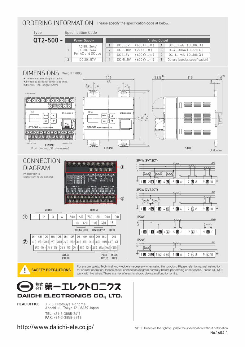
DIMENSIONS
CONNECTIONDIAGRAM
FRONT(Front cover and USB cover opened) SIDE
Unit: mm
SAFETY PRECAUTIONSFor ensure safety, Technical knowledge is necessary when using this product. Please refer to manual instruction for correct operation. Please check connection diagram carefully before performing connections. Please DO NOT work with live wires. There is a risk of electric shock, device malfunction or fi re.
Please specify the specifi cation code at below.
*1 when wall mouting is attache.*2 when all terminal cover is opened.*3 for DIN RAIL (height:15mm)
Photograph is when front cover opened.
QT2-500 -Type Specifi cation Code
Power Supply
1 AC 80...264V DC 80...264V
For AC and DC use
2 DC 20...57V
Analog Output
1 DC 0...5V ( 600Ω ...∞ ) A DC 0...1mA ( 0...10kΩ )
2 DC 0...10V ( 2kΩ ...∞ ) B DC 4...20mA ( 0...550Ω )
3 DC 1...5V ( 600Ω ...∞ ) C DC -1...1mA ( 0...10kΩ )
4 DC -5...5V ( 600Ω ...∞ ) Z Others (special specifi cation)
ORDERING INFORMATION
1P2W
1P3W
3P3W (2VT,2CT)
3P4W (3VT,3CT)
②
①
①
②
HEAD OFFICE 11-13, Hitotsuya 1-chome, Adachi-ku, Tokyo 121-8639 Japan
TEL: +81-3-3885-2411 FAX: +81-3-3858-3966
http://www.daiichi-ele.co.jp/
Weight:700g
NOTE: Reserves the right to update the specifi cation without notifi cation.No.1604-1
FRONT