Embed Size (px)
Citation preview
Journal of Engineering Science and Technology Vol. 15, No. 3 (2020) 1705 - 1718 © School of Engineering, Taylor’s University
1705
COMPLEXITY REDUCTION OF SLANTLET TRANSFORM STRUCTURE BASED ON THE MULTIPLIERLESS REALIZATION
ABDULHAMED M. JASIM1,*, HAMAM M. ABD1, JASSIM M. ABDUL-JABBAR2
1Electronic Eng. Department, College of Electronics Eng., Ninevah University, Mosul, Iraq 2Computer Engineering Department, College of Eng., University of Mosul, Mosul, Iraq
*Corresponding Author: [email protected]
Abstract
The Slantlet transform (SLT) is a set of parallel filters, which are originally an orthogonal discrete wavelet transform (DWT). The SLT is recently a method to improve some properties of DWT, such as time localization. In this paper, a complexity reduction of SLT is proposed by reducing the mathematical computations of SLT filters based on the method of sum-of-powers-of-two (SOPOT) representation. Modifications of all coefficients of SLT filters can result in a multiplierless realization. The original and the modified magnitude and phase responses of the SLT filters are plotted. Moreover, the maximum and average errors in magnitude and phase responses between the original and modified filters are evaluated. The ECG signal is used as a case of study. The mean square error (MSE) value and the percent root mean square difference (PRD) are used as tools to refer to the amount of similarity. Furthermore, it is noteworthy that these error values are very small between the original and modified filters. Consequently, the new realization leads to a less-complex realization of the Slantlet transform with very small errors.
Keywords: ECG signal, Less-complex, Magnitude and phase responses, Multiplierless realization, Slantlet transform, SOPOT.
1706 A. M. Jasim et al.
Journal of Engineering Science and Technology June 2020, Vol. 15(3)
1. Introduction The discrete wavelet transform (DWT) is an efficient technique in the field of signal processing where it used in several of practical applications such as signal and image processing for analysing, de-noising, compression, and estimation. DWT offers a proportionally efficient representation of piecewise signals. On the other hand, it is an effective tool especially for the applications that need to multi-resolution analysis. It provides variable windows which are short at high frequencies and long at low frequencies [1].
One of weak points in DWT that it is unable to produce an optimal discrete time basis for limited number of zero moments, to overcome this problem, Selesnick proposed in 1999 a type of filters like DWT, namely Slantlet filters, which provides a best performance compared to DWT by their improvements of the time localization properties [2].
The Slantlet Transform (SLT) is recently an advanced multi-resolution technique which is suitable for a piecewise linear data. Just like DWT, the Slantlet filters are orthogonal and can offer multi-resolution decomposition. Moreover, they provide an octave band and zero-moment characteristics, SLT filters can take the same minimum number of level of decomposition (L=2) like DWT. The filters of SLT are implemented in a parallel structure by employing different filters for each scale, whereas the DWT filters are usually implemented as a tree structure based on filter bank iteration [3, 4].
It has been talked by Selesnick [2] that Slantlet filters have some features that make it better than the classical DWT and the conventional DCT. These facts were then proved through the simulation of Panda et al. [3]. Benefits from the specifications and features of the SLT were investigated by more researches, such as Maitra and Chatterjee who proposed in 2006, the development of an automated brain MRI diagnostic system using the Slantlet features, leading to excellent classification with 100% accuracy, while utilizing only six features for the classifier input [5]. Also, Abou-Loukh et al. [6] used a method to accurately classify ECG arrhythmias through a combination of Slantlet transform and artificial neural network (ANN) where the overall accuracy of classification of that approach was 98.40%. Mundher et al. [7], introduced a watermark approach embedded in the cover image (three channels Red, Green and Blue) using discrete Slantlet transform. The results of the approach proved that the best channel was the Blue.
Patil and Patil [8], introduced the Slantlet transform to protect patient confidential data where the proposed method allowed ECG signal to hide patient confidential data and other physiological information. Some metrics were used then to evaluate the effectiveness of the technique; such as Peak Signal to Noise Ratio (PSNR), Percentage Residual Difference (RD %) and Bit Error Rate (BER). The results proved the possibility of better similarity and diagnosis measurement of watermarked ECG [8]. Many other applications can be seen in [9-12] respectively for efficient systems and approaches for steganography, classification of overcurrent and inrush current for power system reliability, speech compression and authentication.
Recently, Bam and Kasana [13] had proposed a method for the security of watermark and the cover image based on Slantlet transformation along with RS vector. The compared experimental results indicated that the PSNR between cover
Complexity Reduction of Slantlet Transform Structure Based on the . . . . 1707
Journal of Engineering Science and Technology June 2020, Vol. 15(3)
and watermarked image was improved while the biometric security was applied for the integrity of the designed watermarking .
This paper introduces a less-complex realization of the SLT filter structures which leads to some reductions in mathematical operations based on the concept of multiplierless representation. This kind of complexity reduction have been previously applied to some DWT structures [14, 15]. All multipliers of SLT filters can be approximated and represented depending on the method of sum-of-powers-of-two (SOPOT) as a multiplierless realization. In SOPOT representation, each multiplier coefficient will be mathematically represented in the form 2±𝑟𝑟 ± 2±𝑠𝑠, where r and s are integer values. Concequently in hardware, it is known that the multiplierless representation leads to highly-efficient performance, less complexity, less processing time, less heat accumulation and inexpensive structure.
Besides this section, Section 2 contains an overview of the SLT filter banks with their constructions based on the structure of DWT regarding the notations which are used in the SLT filters. In addition, the supported length and the derivations of the coefficients of such filters, which can be considered as important improvement compared to DWT filters are also given. In section 3, the less-complex realization of the SLT filters coefficients is considered. This realization is produced based on the SOPOT representation with minimum average amount of error in the magnitude and phase responses of the resulting filters. In section 4, a case study is introduced to compare the amount of similarity between the obtained coefficients of the SLT filters in either of the following two cases: first, the implementation based on the original values of the multipliers, and their counterparts; implemented based on multiplierless representation. The performance evaluation is highlighted by calculating the MSE and PRD functions for ten different samples of some standard ECG signals. Finally, Section 5 sums up the conclusions of this paper.
2. Filter Banks of SLT
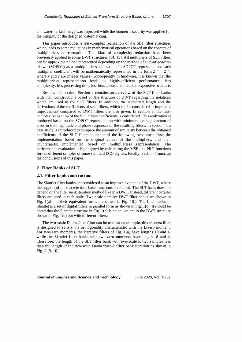
2.1. Filter bank construction The Slantlet filter banks are considered as an improved version of the DWT, where the support of the discrete time basis functions is reduced. The SLT basis does not depend on the filter bank iteration method like in a DWT. Instead, different parallel filters are used in each scale. Two-scale iterative DWT filter banks are shown in Fig. 1(a) and their equivalent forms are shown in Fig. 1(b). The filter banks of Slantlet is a set of digital filters in parallel form as shown in Fig. 1(c). It should be noted that the Slantlet structure in Fig. 1(c) is an equivalent to the DWT structure shown in Fig. 1(b) but with different filters.
The two-scale Daubechies filter can be used as an example; this shortest filter is designed to satisfy the orthogonality characteristic with the k-zero moment. For two-zero moments, the iterative filters of Fig. 1(a) have lengths 10 and 4, while the Slantlet filter banks with two-zero moments have lengths 8 and 4. Therefore, the length of the SLT filter bank with two-scale is two samples less than the length of the two-scale Daubechies-2 filter bank iteration as shown in Fig. 2 [9, 10].
1708 A. M. Jasim et al.
Journal of Engineering Science and Technology June 2020, Vol. 15(3)
(a) Two-scale DWT filter banks. (b) Two-scale equivalent structure of
DWT.
(c) Two-scale SLT filter banks structure.
Fig. 1. Two-scale filter bank and an equivalent structure.
2.2. Branches of the SLT with support length filters The filter bank of SLT consist of a set of parallel filters with time responses of ℎ𝑖𝑖(𝑛𝑛), 𝑓𝑓𝑖𝑖(𝑛𝑛), and 𝑔𝑔𝑖𝑖(𝑛𝑛) where i indicates to the scale. The filters length for scale i is commensurate to 2i, and this is approximately correct for iterated filter banks. This can be applied for SLT filter banks precisely.
The l scale filter banks have 2l channels. The ℎ𝑙𝑙(𝑛𝑛) filter is called a low pass filter and the adjacent filter to the low pass is called 𝑓𝑓𝑙𝑙(𝑛𝑛) filter. ℎ𝑙𝑙(𝑛𝑛) and 𝑓𝑓𝑙𝑙(𝑛𝑛) filters are followed by down sampling by 2l. The remaining channels (2𝑙𝑙 − 2 ), which are filtered by 𝑔𝑔𝑖𝑖(𝑛𝑛) filter and its shifted time-reversed version 𝑔𝑔𝑖𝑖((2𝑖𝑖+1 − 1) − 𝑛𝑛) for 𝑖𝑖 = 1, … . , 𝑙𝑙 − 1, are followed by (2𝑖𝑖+1) down sampling for each value 𝑖𝑖.
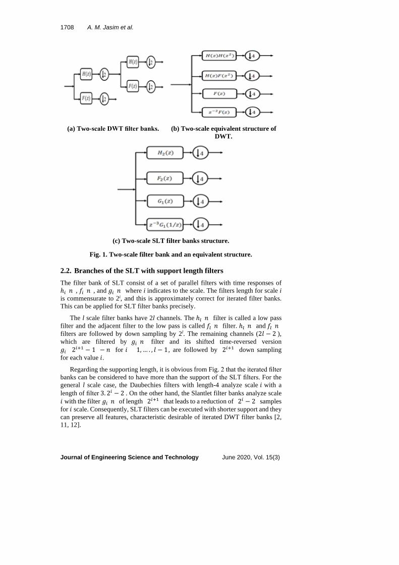
Regarding the supporting length, it is obvious from Fig. 2 that the iterated filter banks can be considered to have more than the support of the SLT filters. For the general l scale case, the Daubechies filters with length-4 analyze scale 𝑖𝑖 with a length of filter 3. 2𝑖𝑖 − 2 . On the other hand, the Slantlet filter banks analyze scale 𝑖𝑖 with the filter 𝑔𝑔𝑖𝑖(𝑛𝑛) of length (2𝑖𝑖+1) that leads to a reduction of (2𝑖𝑖 − 2) samples for 𝑖𝑖 scale. Consequently, SLT filters can be executed with shorter support and they can preserve all features, characteristic desirable of iterated DWT filter banks [2, 11, 12].
Complexity Reduction of Slantlet Transform Structure Based on the . . . . 1709
Journal of Engineering Science and Technology June 2020, Vol. 15(3)
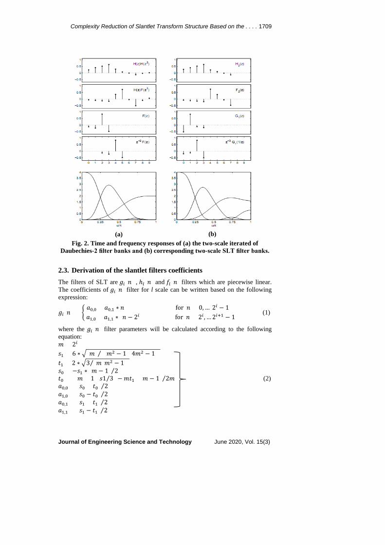
Fig. 2. Time and frequency responses of (a) the two-scale iterated of Daubechies-2 filter banks and (b) corresponding two-scale SLT filter banks.
2.3. Derivation of the slantlet filters coefficients The filters of SLT are 𝑔𝑔𝑖𝑖(𝑛𝑛) , ℎ𝑙𝑙(𝑛𝑛) and 𝑓𝑓𝑙𝑙(𝑛𝑛) filters which are piecewise linear. The coefficients of 𝑔𝑔𝑖𝑖(𝑛𝑛) filter for l scale can be written based on the following expression:
𝑔𝑔𝑖𝑖(𝑛𝑛) = �𝑎𝑎0,0 + 𝑎𝑎0,1 ∗ 𝑛𝑛 for 𝑛𝑛 = 0, … 2𝑖𝑖 − 1
𝑎𝑎1,0 + 𝑎𝑎1,1 ∗ (𝑛𝑛 − 2𝑖𝑖) for 𝑛𝑛 = 2𝑖𝑖 , … 2𝑖𝑖+1 − 1 (1)
where the 𝑔𝑔𝑖𝑖(𝑛𝑛) filter parameters will be calculated according to the following equation: 𝑚𝑚 = 2𝑖𝑖 𝑠𝑠1 = 6 ∗ �(𝑚𝑚) ((𝑚𝑚2 − 1)(4𝑚𝑚2 − 1))⁄ 𝑡𝑡1 = 2 ∗ �3 (𝑚𝑚(𝑚𝑚2 − 1))⁄ 𝑠𝑠0 = −𝑠𝑠1 ∗ (𝑚𝑚 − 1) 2⁄ 𝑡𝑡0 = ((𝑚𝑚 + 1)(𝑠𝑠1 3⁄ ) −𝑚𝑚𝑡𝑡1)((𝑚𝑚 − 1) 2𝑚𝑚⁄ ) (2) 𝑎𝑎0,0 = (𝑠𝑠0 + 𝑡𝑡0) 2⁄ 𝑎𝑎1,0 = (𝑠𝑠0 − 𝑡𝑡0) 2⁄ 𝑎𝑎0,1 = (𝑠𝑠1 + 𝑡𝑡1) 2⁄ 𝑎𝑎1,1 = (𝑠𝑠1 − 𝑡𝑡1) 2⁄
(a) (b)
1710 A. M. Jasim et al.
Journal of Engineering Science and Technology June 2020, Vol. 15(3)
Note that the value of parameters 𝑎𝑎0,0, 𝑎𝑎0,1, 𝑎𝑎1,0, and 𝑎𝑎1,1 which represent the values of the coefficients depend on 2𝑖𝑖 , where 𝑖𝑖 = 𝑙𝑙 − 1 . The same approach works for ℎ𝑙𝑙(𝑛𝑛) and 𝑓𝑓𝑙𝑙(𝑛𝑛) filters which are based on a piecewise linear form. It can be written in terms of eight unknown parameters 𝑏𝑏0,0, 𝑏𝑏0,1, 𝑏𝑏1,0, 𝑏𝑏1,1, 𝑐𝑐0,0, 𝑐𝑐0,1,𝑐𝑐1,0, and 𝑐𝑐1,1.
ℎ𝑖𝑖(𝑛𝑛) = �𝑏𝑏0,0 + 𝑏𝑏0,1 ∗ 𝑛𝑛 for 𝑛𝑛 = 0, … 2𝑖𝑖 − 1
𝑏𝑏1,0 + 𝑏𝑏1,1 ∗ (𝑛𝑛 − 2𝑖𝑖) for 𝑛𝑛 = 2𝑖𝑖 , … 2𝑖𝑖+1 − 1
𝑓𝑓𝑖𝑖(𝑛𝑛) = �𝑐𝑐0,0 + 𝑐𝑐0,1 ∗ 𝑛𝑛 for 𝑛𝑛 = 0, … 2𝑖𝑖 − 1
𝑐𝑐1,0 + 𝑐𝑐1,1 ∗ (𝑛𝑛 − 2𝑖𝑖) for 𝑛𝑛 = 2𝑖𝑖 , … 2𝑖𝑖+1 − 1 (3)
where the parameters of ℎ𝑖𝑖(𝑛𝑛) and 𝑓𝑓𝑖𝑖(𝑛𝑛) filters are calculated according to the following equations:
𝑚𝑚 = 2𝑖𝑖
𝑣𝑣 = �(2𝑚𝑚2 + 1) 3⁄ 𝑢𝑢 = 1 √𝑚𝑚⁄
𝑞𝑞 = �3/(𝑚𝑚(𝑚𝑚2 − 1))/3 𝑏𝑏0,0 = 𝑢𝑢(𝑣𝑣 + 1) 2𝑚𝑚⁄ 𝑏𝑏0,1 = 𝑢𝑢 𝑚𝑚⁄ 𝑏𝑏1,0 = 𝑢𝑢 − 𝑏𝑏0,0 𝑏𝑏1,1 = −𝑏𝑏0,1 (4) 𝑐𝑐0,1 = 𝑞𝑞(𝑣𝑣 − 𝑚𝑚) 𝑐𝑐0,0 = 𝑐𝑐0,1(𝑣𝑣 + 1)/2 𝑐𝑐1,1 = −𝑞𝑞(𝑣𝑣 + 𝑚𝑚) 𝑐𝑐1,0 = 𝑐𝑐1,1(𝑣𝑣 + 1 − 2𝑚𝑚)/2
3. Multiplierless Representations In this paper, a less-complex realization of SLT is proposed by reducing the mathematical computations of SLT filters based on the method of SOPOT representation. Representing the coefficients of any filter based on the method of SOPOT will allow reducing the number of multiplier blocks, and that’s lead to simple implementations for the coefficients by applying a limited number of operations such as adders and shifters without using any multiplication. On the other hand, fewer number of adders requires less consumed power and significantly reduces the overall complexity [16, 17].
As shown in Fig. 1(c) the two-scale SLT have four filters; 𝐻𝐻2(𝑧𝑧), 𝐹𝐹2(𝑧𝑧), 𝐺𝐺1(𝑧𝑧), and the shifted time-reversed 𝐺𝐺1(𝑧𝑧) version, ( 𝐺𝐺𝐺𝐺(𝑧𝑧) = 𝑧𝑧−3𝐺𝐺1(1 𝑧𝑧⁄ )) . The coefficients of SLT filters can be expressed as follows [2]:
𝐺𝐺1(𝑧𝑧) = �− √1020
− √24� + �3√10
20+ √2
4� 𝑍𝑍−1 + �− 3√10
20+ √2
4� 𝑍𝑍−2 + �√10
20− √2
4� 𝑍𝑍−3 (5)
𝐺𝐺𝐺𝐺(𝑧𝑧) = 𝑍𝑍−3𝐺𝐺1�1𝑍𝑍� � = �√10
20− √2
4� + �− 3√10
20+ √2
4� 𝑍𝑍−1 + �3√10
20+ √2
4� 𝑍𝑍−2 +
�−√1020
− √24� 𝑍𝑍−3 (6)
Complexity Reduction of Slantlet Transform Structure Based on the . . . . 1711
Journal of Engineering Science and Technology June 2020, Vol. 15(3)
𝐻𝐻2(𝑧𝑧) = � 116
+ √1116� + � 3
16+ √11
16� 𝑍𝑍−1 + � 5
16+ √11
16� 𝑍𝑍−2 + � 7
16+ √11
16� 𝑍𝑍−3 +
� 716− √11
16� 𝑍𝑍−4 + � 5
16− √11
16� 𝑍𝑍−5 + � 3
16− √11
16� 𝑍𝑍−6 + � 1
16− √11
16� 𝑍𝑍−7 (7)
𝐹𝐹2(𝑧𝑧) = �7√580
− 2√5580
� + �−√580− 2√55
80� 𝑍𝑍−1 + �− 9√5
80+ √55
80� 𝑍𝑍−2 + �− 17√5
80+
3√5580
� 𝑍𝑍−3 + �17√580
+ 3√5580
� 𝑍𝑍−4 + �9√580
+ √5580� 𝑍𝑍−5 + �√5
80− √55
80� 𝑍𝑍−6 +
�− 7√580
− 3√5580
� 𝑍𝑍−7 (8)
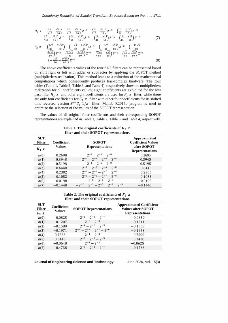
The above coefficients values of the four SLT filters can be represented based on shift right or left with adder or subtractor by applying the SOPOT method (multiplierless realization). This method leads to a reduction of the mathematical computations which consequently produces less-complex hardware. The four tables (Table 1, Table 2, Table 3, and Table 4), respectively show the multiplierless realization for all coefficients values; eight coefficients are exploited for the low pass filter 𝐻𝐻2(𝑧𝑧) and other eight coefficients are used for 𝐹𝐹2(𝑧𝑧) filter, while there are only four coefficients for 𝐺𝐺1(𝑧𝑧) filter with other four coefficients for its shifted time-reversed version 𝑍𝑍−3𝐺𝐺1(1/𝑧𝑧) filter. Matlab R2015b program is used to optimize the selection of the values of the SOPOT representation.
The values of all original filter coefficients and their corresponding SOPOT representations are explained in Table 1, Table 2, Table 3, and Table 4, respectively.
Table 1. The original coefficients of 𝑯𝑯𝟐𝟐(𝒛𝒛) filter and their SOPOT representations.
SLT Filter Coefficient
Values SOPOT
Representations
Approximated Coefficient Values
after SOPOT Representations 𝑯𝑯𝟐𝟐(𝒛𝒛)
h(0) 0.2698 2−2 + 2−6 + 2−8 0.2695 h(1) 0.3948 2−2 + 2−3 + 2−6 + 2−8 0.3945 h(2) 0.5198 2−1 + 2−6 + 2−8 0.5195 h(3) 0.6448 2−1 + 2−3 + 2−6 + 2−8 0.6445 h(4) 0.2302 2−2 − 2−6 − 2−7 + 2−8 0.2305 h(5) 0.1052 2−3 − 2−6 − 2−7 + 2−8 0.1055 h(6) −0.0198 −2−5 + 2−7 + 2−8 −0.0195 h(7) −0.1448 −2−2 + 2−3 − 2−5 + 2−7 + 2−8 −0.1445
Table 2. The original coefficients of 𝑭𝑭𝟐𝟐(𝒛𝒛) filter and their SOPOT representations.
SLT Filter Coefficient
Values SOPOT Representations Approximated Coefficient
Values after SOPOT Representations 𝑭𝑭𝟐𝟐(𝒛𝒛)
h(0) −0.0825 2−5 − 2−3 + 2−7 −0.0859 h(1) −0.1207 2−8 − 2−3 −0.1211 h(2) −0.1589 2−4 − 2−2 + 2−5 −0.1563 h(3) −0.1971 2−4 − 2−2 + 2−7 − 2−6 −0.1953 h(4) 0.7533 2−1 + 2−2 0.7500 h(5) 0.3443 2−2 + 2−3 − 2−5 0.3438 h(6) −0.0648 2−4 − 2−3 −0.0625 h(7) −0.4738 2−5 − 2−1 − 2−7 −0.4766
1712 A. M. Jasim et al.
Journal of Engineering Science and Technology June 2020, Vol. 15(3)
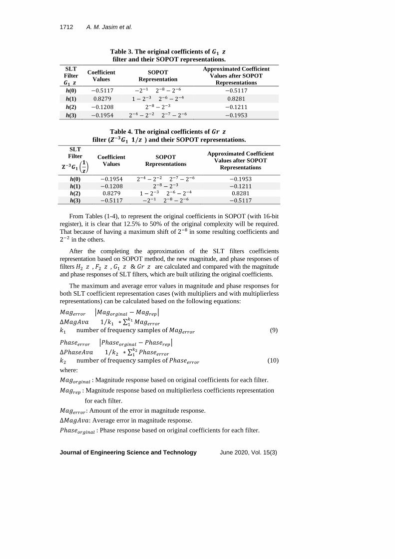
Table 3. The original coefficients of 𝑮𝑮𝟏𝟏(𝒛𝒛) filter and their SOPOT representations.
SLT Filter Coefficient
Values SOPOT
Representation
Approximated Coefficient Values after SOPOT
Representations 𝑮𝑮𝟏𝟏(𝒛𝒛) h(0) −0.5117 −2−1 + 2−8 − 2−6 −0.5117 h(1) 0.8279 1 − 2−3 + 2−6 − 2−4 0.8281 h(2) −0.1208 2−8 − 2−3 −0.1211 h(3) −0.1954 2−4 − 2−2 + 2−7 − 2−6 −0.1953
Table 4. The original coefficients of 𝑮𝑮𝑮𝑮(𝒛𝒛) filter (𝒁𝒁−𝟑𝟑𝑮𝑮𝟏𝟏(𝟏𝟏/𝒛𝒛)) and their SOPOT representations.
SLT Filter Coefficient
Values SOPOT
Representations
Approximated Coefficient Values after SOPOT
Representations 𝐙𝐙−𝟑𝟑𝑮𝑮𝟏𝟏 �𝟏𝟏𝒛𝒛�
h(0) −0.1954 2−4 − 2−2 + 2−7 − 2−6 −0.1953 h(1) −0.1208 2−8 − 2−3 −0.1211 h(2) 0.8279 1 − 2−3 + 2−6 − 2−4 0.8281 h(3) −0.5117 −2−1 + 2−8 − 2−6 −0.5117
From Tables (1-4), to represent the original coefficients in SOPOT (with 16-bit register), it is clear that 12.5% to 50% of the original complexity will be required. That because of having a maximum shift of 2−8 in some resulting coefficients and 2−2 in the others.
After the completing the approximation of the SLT filters coefficients representation based on SOPOT method, the new magnitude, and phase responses of filters 𝐻𝐻2(𝑧𝑧), 𝐹𝐹2(𝑧𝑧), 𝐺𝐺1(𝑧𝑧) & 𝐺𝐺𝐺𝐺(𝑧𝑧) are calculated and compared with the magnitude and phase responses of SLT filters, which are built utilizing the original coefficients.
The maximum and average error values in magnitude and phase responses for both SLT coefficient representation cases (with multipliers and with multiplierless representations) can be calculated based on the following equations:
𝑀𝑀𝑎𝑎𝑔𝑔𝑒𝑒𝑟𝑟𝑟𝑟𝑒𝑒𝑟𝑟 = �𝑀𝑀𝑎𝑎𝑔𝑔𝑒𝑒𝑟𝑟𝑜𝑜𝑖𝑖𝑜𝑜𝑜𝑜𝑙𝑙 − 𝑀𝑀𝑎𝑎𝑔𝑔𝑟𝑟𝑒𝑒𝑟𝑟� ∆𝑀𝑀𝑎𝑎𝑔𝑔𝑀𝑀𝑣𝑣𝑎𝑎 = (1 𝑘𝑘1⁄ ) ∗ ∑ 𝑀𝑀𝑎𝑎𝑔𝑔𝑒𝑒𝑟𝑟𝑟𝑟𝑒𝑒𝑟𝑟
𝑘𝑘11
𝑘𝑘1 = number of frequency samples of 𝑀𝑀𝑎𝑎𝑔𝑔𝑒𝑒𝑟𝑟𝑟𝑟𝑒𝑒𝑟𝑟 (9)
𝑃𝑃ℎ𝑎𝑎𝑠𝑠𝑎𝑎𝑒𝑒𝑟𝑟𝑟𝑟𝑒𝑒𝑟𝑟 = �𝑃𝑃ℎ𝑎𝑎𝑠𝑠𝑎𝑎𝑒𝑒𝑟𝑟𝑜𝑜𝑖𝑖𝑜𝑜𝑜𝑜𝑙𝑙 − 𝑃𝑃ℎ𝑎𝑎𝑠𝑠𝑎𝑎𝑟𝑟𝑒𝑒𝑟𝑟� ∆𝑃𝑃ℎ𝑎𝑎𝑠𝑠𝑎𝑎𝑀𝑀𝑣𝑣𝑎𝑎 = (1 𝑘𝑘2⁄ ) ∗ ∑ 𝑃𝑃ℎ𝑎𝑎𝑠𝑠𝑎𝑎𝑒𝑒𝑟𝑟𝑟𝑟𝑒𝑒𝑟𝑟
𝑘𝑘21
𝑘𝑘2 = number of frequency samples of 𝑃𝑃ℎ𝑎𝑎𝑠𝑠𝑎𝑎𝑒𝑒𝑟𝑟𝑟𝑟𝑒𝑒𝑟𝑟 (10) where: 𝑀𝑀𝑎𝑎𝑔𝑔𝑒𝑒𝑟𝑟𝑜𝑜𝑖𝑖𝑜𝑜𝑜𝑜𝑙𝑙 : Magnitude response based on original coefficients for each filter. 𝑀𝑀𝑎𝑎𝑔𝑔𝑟𝑟𝑒𝑒𝑟𝑟 : Magnitude response based on multiplierless coefficients representation for each filter. 𝑀𝑀𝑎𝑎𝑔𝑔𝑒𝑒𝑟𝑟𝑟𝑟𝑒𝑒𝑟𝑟: Amount of the error in magnitude response. ∆𝑀𝑀𝑎𝑎𝑔𝑔𝑀𝑀𝑣𝑣𝑎𝑎: Average error in magnitude response. 𝑃𝑃ℎ𝑎𝑎𝑠𝑠𝑎𝑎𝑒𝑒𝑟𝑟𝑜𝑜𝑖𝑖𝑜𝑜𝑜𝑜𝑙𝑙 : Phase response based on original coefficients for each filter.
Complexity Reduction of Slantlet Transform Structure Based on the . . . . 1713
Journal of Engineering Science and Technology June 2020, Vol. 15(3)
𝑃𝑃ℎ𝑎𝑎𝑠𝑠𝑎𝑎𝑟𝑟𝑒𝑒𝑟𝑟 : Phase response based on multiplierless coefficients representation for each filter. 𝑃𝑃ℎ𝑎𝑎𝑠𝑠𝑎𝑎𝑒𝑒𝑟𝑟𝑟𝑟𝑒𝑒𝑟𝑟 : Amount of the error in phase response. ∆𝑃𝑃ℎ𝑎𝑎𝑠𝑠𝑎𝑎𝑀𝑀𝑣𝑣𝑎𝑎: Average error in phase response.
It is noteworthy that Table 5 is obtained from Eqs. (9) and (10). From the explained results in Table 5, it's clear that all coefficients of the SLT filters with two-scale filer banks can be represented by the SOPOT method, in which the maximum deviation in the magnitude response does not exceed 0.18%, whereas it reaches 1.7% for the phase responses.
Table 5. Maximum and average deviations of magnitude and phase responses.
SLT Filters Magnitude Response Errors Phase Response Errors
∆𝑀𝑀𝑎𝑎𝑔𝑔𝑀𝑀𝑣𝑣𝑎𝑎 Max (𝑀𝑀𝑎𝑎𝑔𝑔𝑒𝑒𝑟𝑟𝑟𝑟𝑒𝑒𝑟𝑟) ∆𝑃𝑃ℎ𝑎𝑎𝑠𝑠𝑎𝑎𝑀𝑀𝑣𝑣𝑎𝑎 Max
(𝑃𝑃ℎ𝑎𝑎𝑠𝑠𝑎𝑎𝑒𝑒𝑟𝑟𝑟𝑟𝑒𝑒𝑟𝑟) 𝑯𝑯𝟐𝟐(𝒛𝒛) 4.86𝑎𝑎 − 04 0.0013 0.0015 0.2034 𝑭𝑭𝟐𝟐(𝒛𝒛) 0.0018 0.0088 0.0021 0.2223 𝑮𝑮𝟏𝟏(𝒛𝒛) −1.33𝑎𝑎 − 04 6 𝑎𝑎 − 04 0.0170 3.1413
𝑮𝑮𝑮𝑮 = 𝒁𝒁−𝟑𝟑𝑮𝑮𝟏𝟏 �𝟏𝟏𝒛𝒛� −1.33𝑎𝑎 − 04 6 𝑎𝑎 − 04 4.067𝑎𝑎 − 04 0.0081
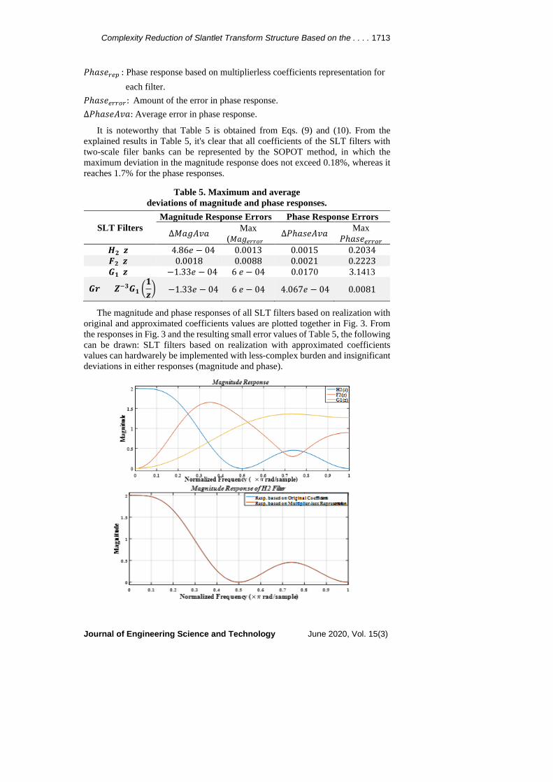
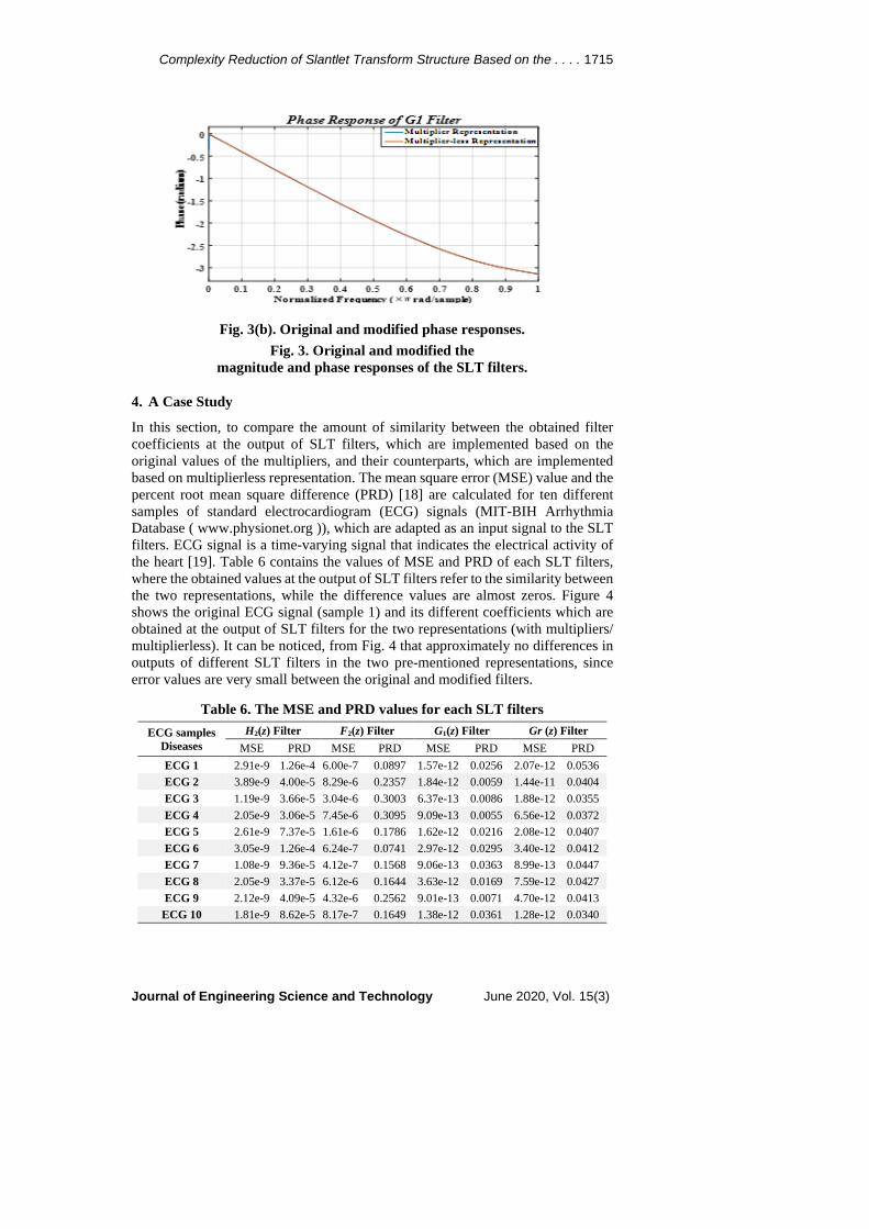
The magnitude and phase responses of all SLT filters based on realization with original and approximated coefficients values are plotted together in Fig. 3. From the responses in Fig. 3 and the resulting small error values of Table 5, the following can be drawn: SLT filters based on realization with approximated coefficients values can hardwarely be implemented with less-complex burden and insignificant deviations in either responses (magnitude and phase).
1714 A. M. Jasim et al.
Journal of Engineering Science and Technology June 2020, Vol. 15(3)
c
Fig. 3(a). Original and modified magnitude responses.
0 0.1 0.2 0.3 0.4 0.5 0.6 0.7 0.8 0.9 1Normalized Frequency ( rad/sample)
0
0.2
0.4
0.6
0.8
1
1.2
1.4
1.6
Mag
nitu
de
Magnitude Response of F2 Filter
Resp. based on Original CoefficientsResp. based on Multiplier-less Representation
0 0.1 0.2 0.3 0.4 0.5 0.6 0.7 0.8 0.9 1
Normalized Frequency ( rad/sample)
0
0.2
0.4
0.6
0.8
1
1.2
1.4
Mag
nitu
de
Magnitude Response of G1 Filter
Resp. based on Original CoefficientsResp. based on Multiplier-less Representation
Complexity Reduction of Slantlet Transform Structure Based on the . . . . 1715
Journal of Engineering Science and Technology June 2020, Vol. 15(3)
Fig. 3(b). Original and modified phase responses. Fig. 3. Original and modified the
magnitude and phase responses of the SLT filters.
4. A Case Study
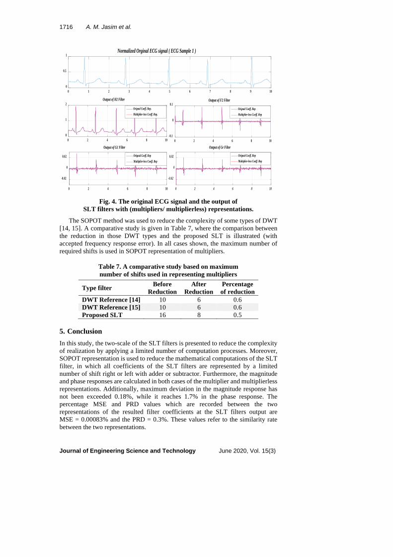
In this section, to compare the amount of similarity between the obtained filter coefficients at the output of SLT filters, which are implemented based on the original values of the multipliers, and their counterparts, which are implemented based on multiplierless representation. The mean square error (MSE) value and the percent root mean square difference (PRD) [18] are calculated for ten different samples of standard electrocardiogram (ECG) signals (MIT-BIH Arrhythmia Database ( www.physionet.org )), which are adapted as an input signal to the SLT filters. ECG signal is a time-varying signal that indicates the electrical activity of the heart [19]. Table 6 contains the values of MSE and PRD of each SLT filters, where the obtained values at the output of SLT filters refer to the similarity between the two representations, while the difference values are almost zeros. Figure 4 shows the original ECG signal (sample 1) and its different coefficients which are obtained at the output of SLT filters for the two representations (with multipliers/ multiplierless). It can be noticed, from Fig. 4 that approximately no differences in outputs of different SLT filters in the two pre-mentioned representations, since error values are very small between the original and modified filters.
Table 6. The MSE and PRD values for each SLT filters Gr (z) Filter G1(z) Filter F2(z) Filter H2(z) Filter ECG samples
Diseases PRD MSE PRD MSE PRD MSE PRD MSE 0.0536 2.07e-12 0.0256 1.57e-12 0.0897 6.00e-7 1.26e-4 2.91e-9 ECG 1 0.0404 1.44e-11 0.0059 1.84e-12 0.2357 8.29e-6 4.00e-5 3.89e-9 ECG 2 0.0355 1.88e-12 0.0086 6.37e-13 0.3003 3.04e-6 3.66e-5 1.19e-9 ECG 3 0.0372 6.56e-12 0.0055 9.09e-13 0.3095 7.45e-6 3.06e-5 2.05e-9 ECG 4 0.0407 2.08e-12 0.0216 1.62e-12 0.1786 1.61e-6 7.37e-5 2.61e-9 ECG 5 0.0412 3.40e-12 0.0295 2.97e-12 0.0741 6.24e-7 1.26e-4 3.05e-9 ECG 6 0.0447 8.99e-13 0.0363 9.06e-13 0.1568 4.12e-7 9.36e-5 1.08e-9 ECG 7 0.0427 7.59e-12 0.0169 3.63e-12 0.1644 6.12e-6 3.37e-5 2.05e-9 ECG 8 0.0413 4.70e-12 0.0071 9.01e-13 0.2562 4.32e-6 4.09e-5 2.12e-9 ECG 9 0.0340 1.28e-12 0.0361 1.38e-12 0.1649 8.17e-7 8.62e-5 1.81e-9 ECG 10
1716 A. M. Jasim et al.
Journal of Engineering Science and Technology June 2020, Vol. 15(3)
Fig. 4. The original ECG signal and the output of
SLT filters with (multipliers/ multiplierless) representations.
The SOPOT method was used to reduce the complexity of some types of DWT [14, 15]. A comparative study is given in Table 7, where the comparison between the reduction in those DWT types and the proposed SLT is illustrated (with accepted frequency response error). In all cases shown, the maximum number of required shifts is used in SOPOT representation of multipliers.
Table 7. A comparative study based on maximum number of shifts used in representing multipliers
Type filter Before Reduction
After Reduction
Percentage of reduction
DWT Reference [14] 10 6 0.6 DWT Reference [15] 10 6 0.6 Proposed SLT 16 8 0.5
5. Conclusion In this study, the two-scale of the SLT filters is presented to reduce the complexity of realization by applying a limited number of computation processes. Moreover, SOPOT representation is used to reduce the mathematical computations of the SLT filter, in which all coefficients of the SLT filters are represented by a limited number of shift right or left with adder or subtractor. Furthermore, the magnitude and phase responses are calculated in both cases of the multiplier and multiplierless representations. Additionally, maximum deviation in the magnitude response has not been exceeded 0.18%, while it reaches 1.7% in the phase response. The percentage MSE and PRD values which are recorded between the two representations of the resulted filter coefficients at the SLT filters output are MSE = 0.00083% and the PRD = 0.3%. These values refer to the similarity rate between the two representations.
0 1 2 3 4 5 6 7 8 9 100
0.5
1Normalized Orginal ECG signal ( ECG Sample 1 )
0 2 4 6 8 100
1
2Output of H2 Filter
Orignal Coeff. Rep.Multiplier-less Coeff. Rep.
0 2 4 6 8 10-0.1
0
0.1Output of F2 Filter
Orignal Coeff. RepMultiplier-less Coeff. Rep
0 2 4 6 8 10
-0.02
0
0.02
Output of G1 Filter
Orignal Coeff. RepMultiplier-less Coeff. Rep
0 2 4 6 8 10
-0.02
0
0.02
Output of Gr Filter
Orignal Coeff. RepMultiplier-less Coeff. Rep
Complexity Reduction of Slantlet Transform Structure Based on the . . . . 1717
Journal of Engineering Science and Technology June 2020, Vol. 15(3)
Nomenclatures 𝑎𝑎0,0 + 𝑎𝑎0,1 + ⋯ Parameters of the 𝑔𝑔𝑖𝑖 filter 𝑏𝑏0,0 + 𝑏𝑏0,1 + ⋯ Parameters of the ℎ𝑖𝑖 filter 𝑐𝑐0,0 + 𝑐𝑐0,1 + ⋯ Parameters of the 𝑓𝑓𝑖𝑖 filter 𝑔𝑔𝑖𝑖(𝑛𝑛), ℎ𝑙𝑙(𝑛𝑛), 𝑓𝑓𝑙𝑙(𝑛𝑛) SLT filters 𝑘𝑘1 Number of frequency samples of 𝑀𝑀𝑎𝑎𝑔𝑔𝑒𝑒𝑟𝑟𝑟𝑟𝑒𝑒𝑟𝑟 𝑘𝑘2 Number of frequency samples of 𝑃𝑃ℎ𝑎𝑎𝑠𝑠𝑎𝑎𝑒𝑒𝑟𝑟𝑟𝑟𝑒𝑒𝑟𝑟 h(0) ⁓ h(n) Coefficients of the SLT filters l Scale of filter banks 𝑀𝑀𝑎𝑎𝑔𝑔 Magnitude response 𝑃𝑃ℎ𝑎𝑎𝑠𝑠𝑎𝑎 Phase response
Abbreviations DWT Discrete Wavelet Transform ECG Electrocardiograph MSE Mean Square Error PRD Percent Root Mean Square Difference SLT Slantlet Transform SOPOT Sum of Powers of Two
References 1. Gursoy, M.I.; Yilmaz, A.S.; and Ustun, S.V. (2018). A practical real-time
power quality event monitoring applications using discrete wavelet transform and artificial neural network. Journal of Engineering Science and Technology, 13(6), 1764-1781.
2. Selesnick, I.W. (1999). The slantlet transform. IEEE Transactions on Signal Processing, 47(5), 1304-1313.
3. Panda, G.; Dash, P.K.; Pradhan, A.K.; and Meher, S.K. (2002). Data compression of power quality events using the slantlet transform. IEEE Transactions on Power Delivery, 17(2), 662-667.
4. Ismaeel, T.Z.; and Hanoon, A. (2012). Design and evolution of a steganography system for speech signal by slantlet transform. Diyala Journal of Engineering Sciences, 5(2), 99-113.
5. Maitra, M.; and Chatterjee, A. (2006). A slantlet transform based intelligent system for magnetic resonance brain image classification. Journal of Biomedical Signal Processing and Control, 1(4), 299-306 .
6. Abou-Loukh, S.J.; Zeyad, T.; and Thabit, R. (2010). ECG classification using slantlet transform and artificial neural network. Journal of Engineering, 16(1), 4510-4528.
7. Mundher, M.; Muhamad, D.; Rehman, A.; Saba, T.; and Kausar, F. (2014). Digital watermarking for images security using discrete slantlet transform. Journal of Applied Mathematics and Information Sciences an International, 8(6), 2823-2830 .
8. Patil, P.B.; and Patil, N.C. (2016). Embedding patient database in ECG signal using slantlet transform for holter monitoring data transmission. International Journal of Scientific Development and Research, 1(6), 444-449 .
1718 A. M. Jasim et al.
Journal of Engineering Science and Technology June 2020, Vol. 15(3)
9. Abduljabbar, R.B. (2016). Steganography system using slantlet transform. Journal of Information, Communication, and Intelligence Systems, 2(1), 1-6.
10. Chatterjee, A.; Maitra, M.; and Goswami, S.K. (2009). Classification of overcurrent and inrush current for power system reliability using slantlet transform and artificial neural network. Journal of Expert Systems with Applications, 36(2), 2391-2399.
11. Sahu, M.K.; Mohan, R.; and Rao, D. (2016). Speech compression using slantlet transform based on different quantization. International Journal of Engineering Research and Management Technology, 3(2), 243-254.
12. Kundu, P.K.; Chatterjee, A.; and Panchariya, P.C. (2011). Electronic tongue system for water sample authentication: a slantlet-transform-based approach. IEEE Transactions on Instrumentation and Measurement, 60(6), 1959-1966.
13. Bamal, R.; and Kasana, S.S. (2018). Slantlet based hybrid-watermarking technique for medical images. International Journal of Multimedia Tools and Applications, 77(10), 12493-12518.
14. Abdul-Jabbar, J.M.; and Jasim, A.M. (2012). Design and multiplierless implementations of ECG-based 1st order gaussian derivative wavelet filter with lattice structures. Journal of University of Anbar for Pure science, 6(2), 124-134.
15. Abdul-Jabbar, J.M.; and Jasim, A.M. (2013). Design and multiplierless realization of ECG-based gaussian wavelet filter with lattice structures. Al-Rafdain Engineering Journal, 21(2), 66-77.
16. Chan, S.C.; Pun, K.S.; and Ho, K.L. (2002). Efficient implementation of wideband multibeam forming network using SOPOT coefficients and multiplier block. 14th International Conference on Digital Signal Processing Proceedings. Santorini, Greece, 243-246.
17. Baudin, R.; and Lesthievent, G. (2014). Design of FIR filters with sum of power-of-two representation using simulated annealing. 7th Advanced Satellite Multimedia Systems Conference and the 13th Signal Processing for Space Communications Workshop. Livorno, Italy, 339-345.
18. Sawant, C.; and Patil, H.T. (2014). ECG signal de-noising using discrete wavelet transform. International Journal of Electronics Communication and Computer Engineering, 5(4), 23-28.
19. Kaur, H.; and Rajni, R. (2017). A novel approach for denoising electrocardiogram signal using hybrid technique. Journal of Engineering Science and Technology, 12(7), 1780-1791.


![Low Complexity Iris Recognition using Curvelet Transform · wavelet transform at various resolution levels of a concentric circle on an iris image to generate the iris code. [n [7],](https://img.pdfslide.us/doc/110x75/5ead18edc826524f507834dc/low-complexity-iris-recognition-using-curvelet-transform-wavelet-transform-at-various.jpg)