Embed Size (px)
Citation preview
International Journal of Latest Research in Engineering and Technology (IJLRET)
ISSN: 2454-5031(Online)
www.ijlret.comǁ Volume 1 Issue 7ǁDecember 2015 ǁ PP 49-90
www.ijlret.com 49 | Page
COMPLEX TRUSS ANALOGY USING PLASTIC AND
ELASTIC ANALYSIS
Ezeagu C.A. and Onunkwo R.C.
Department of Civil Engineering, Faculty of Engineering, Nnamdi Azikiwe University Awka.
ABSTRACT: The work exposes the fundamentals of the plastic and elastic theory of analysis and degree, in
order to sensitize its use. This work also compares the use of plastic method of structural analysis and elastic
method of structural analysis using a complex truss system being acted upon by mobile load as a case study.
This project disputes the common fact that only the elastic method of analysis is used to analyse mobile loads on
truss systems by introducing stipulated steps in plastic method of analysis for analyzing truss systems carrying
mobile loads. This project deals with the creation of a computer application that analyzes and designs structural
trusses. This program was created using the relatively new C# programming language. The project also
discusses various theoretical analysis techniques that can be implemented in developing a computer program.
The main theoretical methods used in this project are influence line analysis and plastic method of analysis of
mobile loads. The Reinforced concrete design is based on the EC3 code. The project solved the reactions on
each member using the influence line analysis for truss system by taking cognizance of the position of the
mobile load (at position x = 2a), at a particular time. The complex truss system was analysed using the plastic
method by unpinning the members of the truss system to form a frame and beams, for easy analysis. This project
designed the complex system using the current code for design regulation i.e. the Euro codes. The bracing
members were analysed and designed as a beam, fixed at the both ends and also at the middle. The results
obtained from the research of this work shows that the influence line analysis generates higher axial forces on
members which include; FC – D = W28a2
2hkN (compression), FC – I, and FC – J =
W2a a2+h2
hkN both in compression
and tension, then FC – J =W2a
3 kN (Tension) and
4W2a
3 kN (compression) and FJ – I =
3W2a2
h kN than the axial forces
generated using the plastic analysis method which also include; Jy =W3a+Mp
a(kN) (maximum compressive axial
force on vertical strut members), Ix =11Mp−2W3a−2W4h
2h kN tension and W4kN tension for both the lower chord
and the top chord respectively, when acted upon by the same magnitude of imposed live loads of W2kN. This is
so because the plastic method of analysis involves a lot of assumptions that makes it yet not advisable to be used
in the analyses of trusses carrying mobile loads.
keywords: Analysis, Elasticity, Load, Plasticity, and system.
Introduction: Engineering is a professional art of applying science to the efficient conversion of natural resources for the
benefit of man. Engineering therefore requires above all creative imagination to innovative useful application
for natural phenomenon (Kamath and Reddy, 2011) Basically there are two approaches to provide adequate strength of structures to support a given set of design
loads: Elastic Design and Plastic Design. Drift checks are also required in actual design practice, but the focus
of discussion herein will be limited to elastic and plastic method of designs on truss systems.
A truss is an assemblage of long, slender structural elements that are connected at their ends. Trusses find
substantial use in modern construction, for instance as towers, bridges, scaffolding, etc. In addition to their
practical importance as useful structures, truss elements have a dimensional simplicity that will help us extend
further the concepts of mechanics introduced in the modules dealing with uniaxial response.
In recent years, the engineers have done a lot of work to know the behaviour of structures, when stressed beyond
the elastic limit called plastic limit. This has led to the development of new theory popularly known as plastic
theory.
With the recent increase in the development of software programs, research engineers have developed computer
aided designs analogy using the available softwares on ground. Structures viz truss structures, concrete
structures e.t.c. are designed using these developed software designs. These computer aided designs include
using the methods of elastic and plastic analogy in the design of trusses.
Aim of the work: This work is aimed at determining the elastic and plastic analysis method of analysing
complex truss systems carrying mobile loads and comparing the both analysis.
COMPLEX TRUSS ANALOGY USING PLASTIC AND ELASTIC ANALYSIS
www.ijlret.com 50 | Page
Objectives of the study: The objectives of the work includes: 1. The comparison between the plastic and elastic methods of analysis and design on truss systems.
2. The elastic cum plastic deformations of structures under mobile loading condition.
3. The various methods of analysing the internal stresses that occur in a structure under external mobile loading eg.
Complex truss system.
4. The fundamental concepts of plastic analysis.
5. Understanding the basis of and limitations of plastic analysis approaches.
Literature Review: A truss is defined as a framework which gives a stable form capable of supporting
considerable external load over a large span with the components parts stressed primarily in axial tension or
compression (Ezeagu and Nwokoye, 2009). In a plane, a truss is composed of relatively slender members often
forming triangular configurations (Mau, 2002).
A truss is one of the major types of engineering structures which provides a practical and economical solution
for many engineering constructions, especially in the design of bridges and buildings that demand large spans
(Ustundag, 2005).
Trusses are statically determinate when all the bar forces can be determined from the equations of statics alone.
Otherwise the truss is statically indeterminate (Saouma, 2007).
Equilibrium is the most important concept of structural analysis. A structure that is initially at rest and remains
at rest when acted upon by applied loads is said to be in a state of equilibrium (Shanmugam and Narayanan,
2008). The resultant of the external loads on the body and the supporting forces or reactions is zero. Engineering
talk about two types of equilibrium; static and dynamic, although it can be argued that static equilibrium is a
special case of dynamic equilibrium. Static equilibrium exists if all parts of a structure can be considered
motionless. I.e. the structural parts, which are initially at rest, remain at rest when acted upon by a system of
force, which therefore suggested that the combined resultant effect of the system of forces shall be neither a
force nor a couple. Otherwise there will be a tendency for motion of the body.
When a structure is in equilibrium, every element or constituent part of it is also in equilibrium. This property is
made use of in developing the concept of the free body diagram for elements of a structure (Buick and Graham,
2003).Compatibility is concerned with deformation. If compatibility is assumed then geometric fit is implied.
That is, if a joint of structure moves, then the ends of the members connected to that joint move by the same
amount, consistent with the nature of the connection. A solution is compatible if the displacement at all points is
not a function of the path. Therefore, a displacement compatible solution involves the existence of a uniquely
defined displacement field (Buick and Graham, 2003).
Compatibility conditions require that the displacements and rotations be continuous throughout the structure and
compatible with the nature supports conditions. For example, at a fixed support this requires that displacement
and slope should be zero (Kharagpur, 2012).
In the case of a pin-jointed frame, compatibility means that the ends of the member at a joint undergo equal
translation. If the framework is rigidly joined, then, in addition to equal translation, the rotation of the ends of
the members meeting at a joint must be equal. According to Okoro (2004) in a project work titled the plastic
behaviour of structures (plastic analysis vs. elastic analysis) stated that the deformation of the structure set up
strains and related internal stresses within the elements. Stress is related to strain through the stress-strain laws,
which is a function of the type of material and the nature of the strain (Spencer, 1988). The best known stress-
strain law is that which defines linear elastic behaviour. In this case, stress is proportional to strain and the
constant of proportionality is Young‟s Modulus [E]. There are other stress-strain laws defining a wide range of
behaviour (like the plastic behaviour) but it should be appreciated that all stress-strain laws are approximates.
The major reason for interest in the assumption of linearity of structural behaviour is that it allows the use of
principle of superposition. This principle means that the displacement resulting from each of a number of forces
may be added to give the displacement resulting from the sum of the forces. Super-position also implies that the
forces corresponding to a number of displacements may be added to yield the force corresponding to the sum of
the displacements. The principle must not be used for analysis of non-linear structures or in the methods of
plastic theory.
Elastic materials are such that returns to its original state after undergoing an extension by an external force
once its elastic limit is not exceeded.
In the analysis of these two behaviour viz: elastic and plastic, there are differences in the mode or method of
analysis: In plastic analysis, the collapse load and load factor used in the design of such structure plays a vital
role. Once these two criteria are adequately catered for in the design, the structure would withstand any applied
force with visible deformations while in the elastic analysis, deflection limit is the major criteria for design. It is
design such that it could remain functional under a certain applied force once the deflection limit is not
exceeded.
The plastic method can be seen as a more rational method for design because all parts of the structure can be
given the same safety factor against collapse. In contrast for elastic methods the safety factor varies. Intrinsically
the plastic method of analysis is simpler than the elastic method because there is no need to satisfy elastic strain
COMPLEX TRUSS ANALOGY USING PLASTIC AND ELASTIC ANALYSIS
www.ijlret.com 51 | Page
compatibilty conditions. However calculations for instability and elastic deflections require careful
consideration when using the plastic method, but nevertheless it is very popular for the design of some
structures (e.g. beams and portal frames) (Martin and Purkiss, 2008).
Deflection becomes the governing factor of elastic analysis while the collapse load and load factor remains basis
of plastic analysis. If these criteria are strictly adhere to in the design of a structure using either of the analysis
method, then the success of the structure to a larger extent is certain. The plastic and elastic method of analysis
has various areas where they are applicable depending on the designer‟s choice and conservation in terms of
material. Since the plastic method of analysis is more economical in terms of material than the elastic method of
analysis.
The plastic method of analysis is used especially in the design of steel structure e.g. rigid frames, indeterminate
rigid frames. Since collapse load is the major criterion that which plastic method is based on, it is adequately
taken care of in the use of this design, thus design of ductile structure is plastic in nature so, plastic design is
basically needed.
It does not mean that elastic method is not also applicable in steel structure, but it is restricted to some extent.
Elastic method is used mainly in the design of reinforced concrete. The ability of a concrete structure to
maintain its shape or form under given deformation or deflection makes it elastic in nature as it would without
some degree of deformations and when exceeded, cracks makes this methods suitable for its use.
According to Okoro (2004) in a project work titled the plastic behaviour of structures (plastic analysis vs. elastic
analysis) stated that the traditional method of showing a typical engineering problem prior to the introduction of
the electronic digital computer was initially by a mathematician or an engineer who endeavoured to obtain a
solution based on strict scientific reasoning and with no regard to the resulting calculation (Litton, 1973).
However, this process was terminated by the introduction of the electronic computer, which provided the
opportunity for a fresh approach to the problem.
Theory of plasticity : The theory of plasticity is the branch of mechanics that deals with the calculation of
stresses and strains in a body, made of ductile material, permanently deformed by a set of applied forces
(Chakrabarty, 2006). The theory is based on certain experimental observations on the macroscopic behaviour of
metals in uniform states of combined stresses. The observed results are then idealized into a mathematical
formulation to describe the behaviour of metals under complex stresses.
Unlike elastic solids, in which the state of strain depends only on the final state of stress, the deformation that
occurs in a plastic solid is determined by the complete history of the loading. The plasticity problem is,
therefore, essentially incremental in nature, the final distortion of the solid being obtained as the sum total of the
incremental distortions following the strain path.
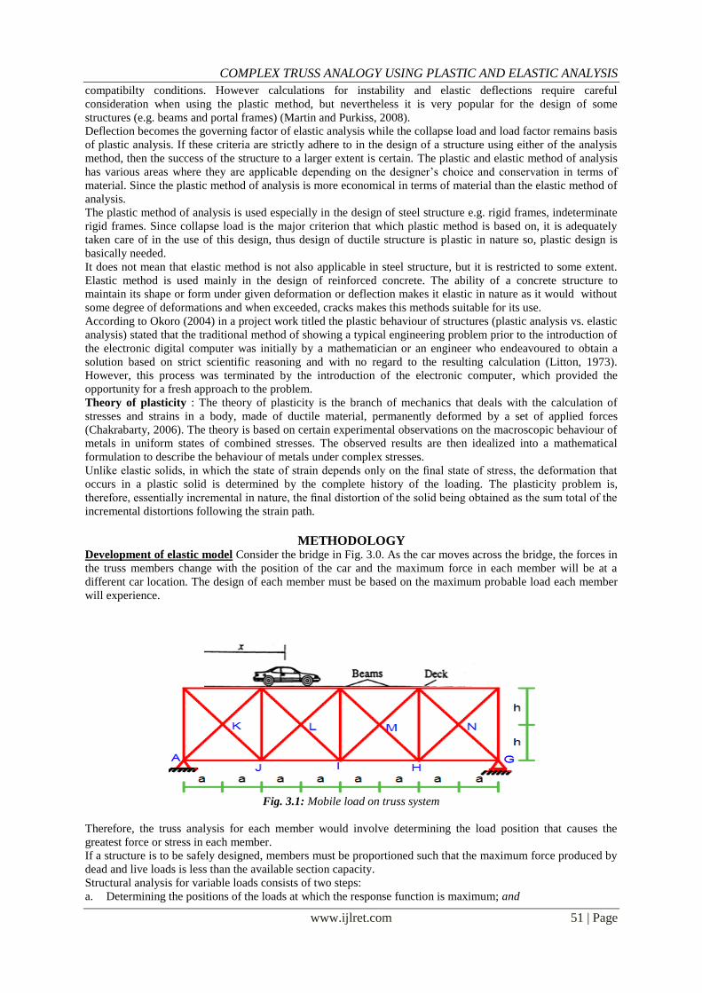
METHODOLOGY Development of elastic model Consider the bridge in Fig. 3.0. As the car moves across the bridge, the forces in
the truss members change with the position of the car and the maximum force in each member will be at a
different car location. The design of each member must be based on the maximum probable load each member
will experience.
Fig. 3.1: Mobile load on truss system
Therefore, the truss analysis for each member would involve determining the load position that causes the
greatest force or stress in each member.
If a structure is to be safely designed, members must be proportioned such that the maximum force produced by
dead and live loads is less than the available section capacity.
Structural analysis for variable loads consists of two steps:
a. Determining the positions of the loads at which the response function is maximum; and
COMPLEX TRUSS ANALOGY USING PLASTIC AND ELASTIC ANALYSIS
www.ijlret.com 52 | Page
b. Computing the maximum value of the response function.
Once an influence line is constructed;
Determine where to place live load on a structure to maximize the drawn response function; and
Evaluate the maximum magnitude of the response function based on the loading.
Consider a through type composite truss of 8 panels, each of length “a” and height “2h” as shown in Fig. 3.0. A
little consideration will show, that the truss consists of;
(i) A primary truss of panels each length of 2a and height 2h. (i.e. with members as CD,JI,CJ,CI and DJ)
(ii) 8 secondary trusses of 1 panel, each of length 2a and of height h as shown in Fig. 3.0
A little consideration will show, that some of the members in the second panel of the primary truss occur in the
primary truss only (e.g. CD, JI, CJ, and DI). Some members occur in both the primary as well as secondary
trusses (e.g. CL, LI, DL and LI). The influence lines for the members, which occur in the primary truss only,
will be given by the influence line for the corresponding member of the primary truss only. But the influence
lines for the members, which occur in both the primary and secondary trusses, may be drawn by joining the
points obtained by algebraically adding the ordinates of the influence lines for the corresponding members in the
primary as well as secondary truss. Cut a section on the member to be analyzed before analyzing.
The maximum force on any member due to a particular moving load is gotten by multiplying the moving load
with the area of the influence line diagram.
Development of plastic model : Consider the truss shown in Fig. 3.0 above, as the load moves on the truss it
distributes a udl on the top cord of the truss system.
Analysis of the complicated truss system as shown above using plastic method of analysis is rather not easy.
Therefore, for easier analysis, the members of the complicated truss system were unpinned into frames, beams
and bracing members. The top chord members and the struts (vertical members) were joined together to form a
continuous frame with uniformly distributed loading of W3kN. The frame is pinned at the end reactions and
fixed at the middle reactions. The internal members are analyzed as a continuous beam with uniformly
distributed loading of W6kN. The continuous beam is pinned at both ends and also at the middle. The lower cord
members were analyzed as a simple beam with uniformly distributed loading of W7kN, pinned at one end and
having roller support at the other end.
N.B – The ratio of the corresponding plastic section modulus (ZP) to the corresponding elastic section modulus
(ZE) of a particular section (both gotten from table) gives the Shape factor (S) of the section. The shape factor is
being multiplied by the factor of safety of the section (1.5) to give the section‟s load factor (LF). The Load factor
multiplied by the corresponding loading on each member gives the total load to be used for the plastic analysis
of the member.
Combined mechanism - The independent mechanisms are combined to determine the maximum Mp value
required to induce collapse with the minimum number of hinges. The shear forces at the various reactions were
obtained. For plastic analysis, the axial forces acting on each member are used for the design of the member and
it also shows whether the member is being acted upon by compression or tension forces.
Design of truss system : The top chord members are designed as I or H steel beam section. The vertical
members (struts) were designed as T or equal long angles back to back steel column section. The internal
bracing members were designed as L- steel bracing section. In the structural design of steel structures, reference
to standard code is essential. As EC3 will eventually replace BS 5950 as the new code of practice, it is necessary
to study and understand the concept of design methods in EC3.
Codes of practice provide detailed guidance and recommendations on design of structural elements. Buckling
resistance and shear resistance are two major elements of structural steel design. Therefore, provision for these
topics is covered in certain sections of the codes. The study on Eurocode 3 in this project will focus on the
subject of moment and shear design.
Design of Steel Beam According to EC3 The design of simply supported steel beam covers all the elements stated below. Sectional size chosen should
satisfy the criteria as stated below:
(i) Cross-sectional classification
(ii) Shear capacity
(iii) Moment capacity (Low shear or High shear)
(iv) Bearing capacity of web
a) Crushing resistance
b) Crippling resistance
c) Buckling resistance
(v) Deflection
COMPLEX TRUSS ANALOGY USING PLASTIC AND ELASTIC ANALYSIS
www.ijlret.com 53 | Page
Analysis, design and comparison works will follow subsequently. Beams and columns are designed for the
maximum moment and shear force obtained from computer software analysis. Checking on several elements,
such as shear capacity, moment capacity, bearing capacity, buckling capacity and deflection is carried out. Next,
analysis on the difference between the results using the two analysis (Elastic and Plastic) is done. Eventually,
comparison of the results will lead to recognizing the difference in design approach for each analysis.
Load distribution : Top Chord members – The top cord members carry a uniformly distributed loading of say
W3kN, which comprises of the total live load acting on the member and the member self weight (dead load).
Both multiplied by their factors of safety.
Vertical members (struts) – The vertical members carry a loading of say W8kN, which comprises of the total
loading coming from the top cord and the wind load multiplied by its factor of safety.
Bracing members – The bracing members are being acted upon by wind loads, their own self weight and------
multiplied by their various factors of safety which is denoted as W9kN.
The lower chord – The lower chord members are being acted upon by the live load and the self-weight of the
whole truss system multiplied by their various factors of safety, denoted in the project as W10kN.
Computer application of plastic and elastic analysis of truss system : For the purpose of this project, we are
going to analyze the complicated truss system using the C# programming language. The elastic and plastic
analysis of complicated truss system discussed in chapter four were encoded in the C# programming language
for easier analysis and to meet up with the growing trend of technology in the modern world.
C# (pronounced "see sharp") is a computerprogramming language. It is developed by Microsoft. It was created
to use all capacities of .NET platform. The first version was released in 2001. The most recent version is C# 5.0,
which was released in August 2012. C# is a modern language
TRUSS ANALYSIS
Member
ref.
Calculation Output
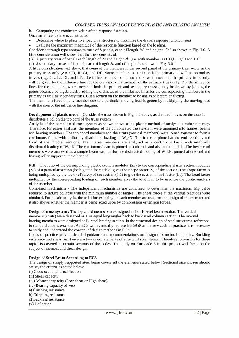
Design data: Span of truss (L) = 8a(m)
Height of truss = 2h(m)
Bracing length = 2 2 + 𝑎2 (m)
Span of each stanchion = 2a(m)
Let position of the load on any member at a particular time be = x
Bracing slope (Ө) = tan-1
2
2𝑎
Let the moving load longer than the span be W2 (kN/m)
Fig. 4.0: Truss system
COMPLEX TRUSS ANALOGY USING PLASTIC AND ELASTIC ANALYSIS
www.ijlret.com 54 | Page
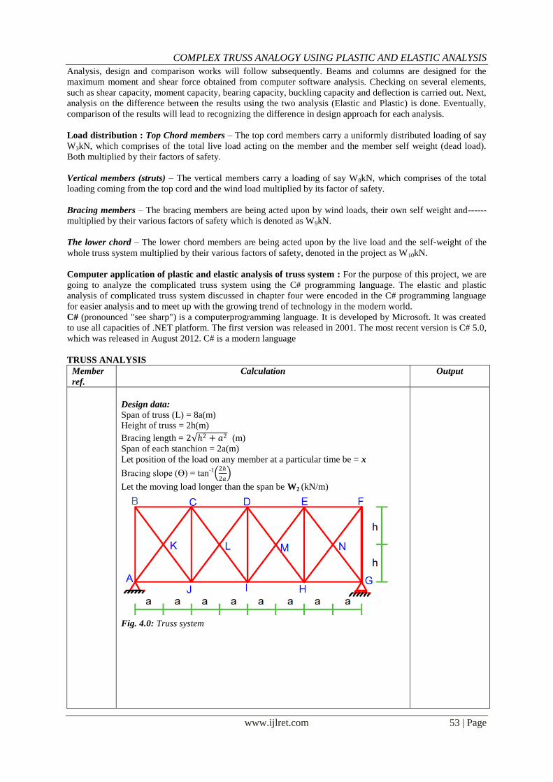
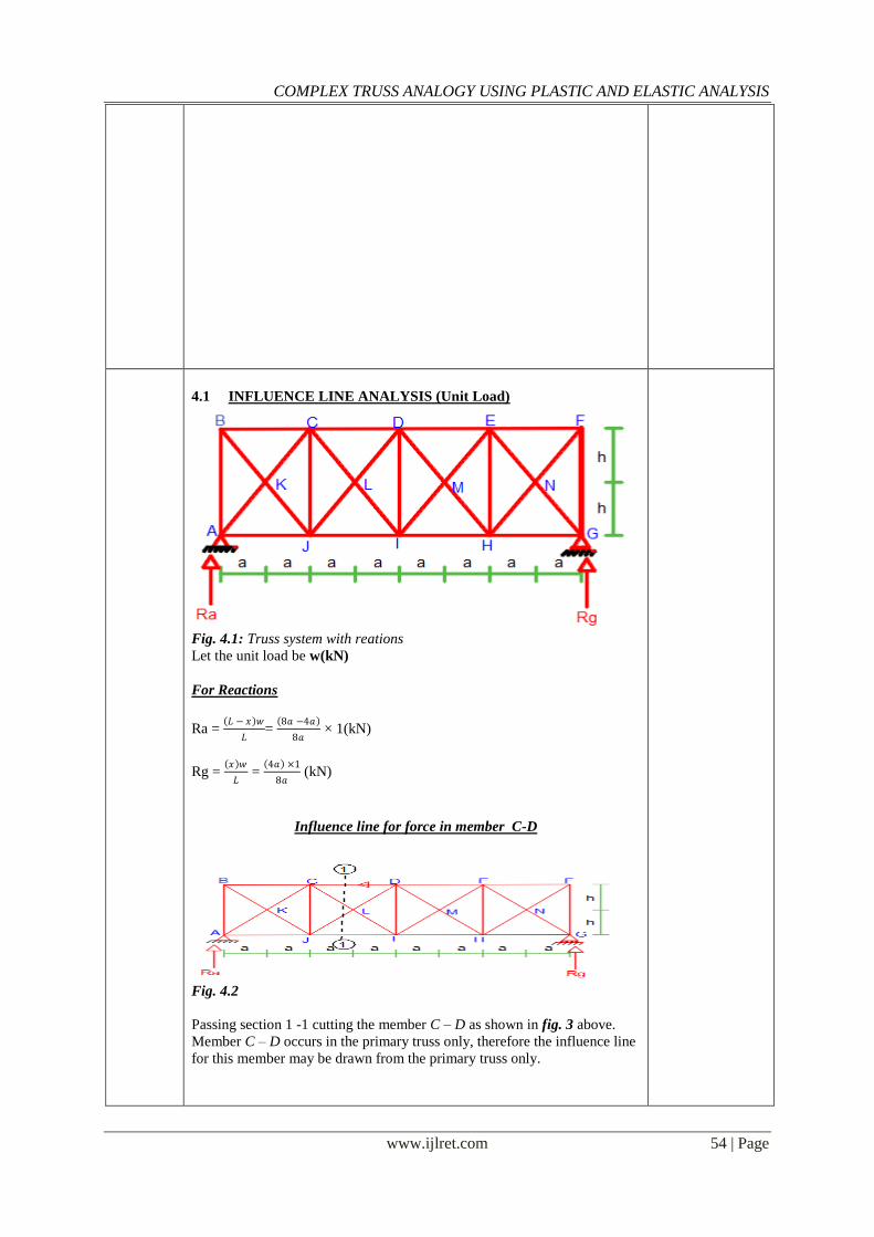
4.1 INFLUENCE LINE ANALYSIS (Unit Load)
Fig. 4.1: Truss system with reations
Let the unit load be w(kN)
For Reactions
Ra = 𝐿 − 𝑥 𝑤
𝐿=
8𝑎 −4𝑎
8𝑎 × 1(kN)
Rg = 𝑥 𝑤
𝐿 =
4𝑎 ×1
8𝑎 (kN)
Influence line for force in member C-D
Fig. 4.2
Passing section 1 -1 cutting the member C – D as shown in fig. 3 above.
Member C – D occurs in the primary truss only, therefore the influence line
for this member may be drawn from the primary truss only.
COMPLEX TRUSS ANALOGY USING PLASTIC AND ELASTIC ANALYSIS
www.ijlret.com 55 | Page
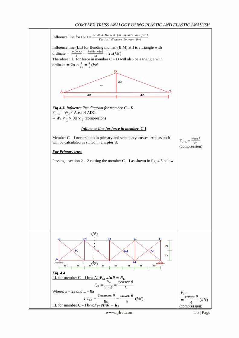
Influence line for C-D = 𝐵𝑒𝑛𝑑𝑖𝑛𝑑 𝑀𝑜𝑚𝑒𝑛𝑡 𝑓𝑜𝑟 𝑖𝑛𝑓𝑙𝑢𝑛𝑐𝑒 𝑙𝑖𝑛𝑒 𝑓𝑜𝑟 𝐼
𝑉𝑒𝑟𝑡𝑖𝑐𝑎𝑙 𝑑𝑖𝑠𝑡𝑎𝑛𝑐𝑒 𝑏𝑒𝑡𝑤𝑒𝑒𝑛 𝐷−𝐼
Influence line (I.L) for Bending moment(B.M) at I is a triangle with
ordinate = 𝑥 𝐿− 𝑥
𝐿=
4𝑎 8𝑎 −4𝑎
8𝑎= 2𝑎(𝑘𝑁)
Therefore I.L for force in member C – D will also be a triangle with
ordinate = 2𝑎 ×1
2=
𝑎
(𝑘𝑁
Fig 4.3: Influence line diagram for member C – D
FC –D = W2 × Area of ADG
= 𝑊2 ×1
2× 8𝑎 ×
𝑎
(compresion)
Influence line for force in member C-I
Member C – I occurs both in primary and secondary trusses. And as such
will be calculated as stated in chapter 3.
For Primary truss
Passing a section 2 – 2 cutting the member C – I as shown in fig. 4.5 below.
FC –D=𝑊28𝑎2
2
(compression)
Fig. 4.4
a) I.L for member C – I b/w AJ:𝑭𝑪𝑰 𝒔𝒊𝒏𝜽 = 𝑹𝑮
𝐹𝐶𝐼 =𝑅𝐺
sin 𝜃=𝑥𝑐𝑜𝑠𝑒𝑐 𝜃
𝐿
Where: x = 2a and L = 8a
𝐼. 𝐿𝐶𝐼 =2𝑎𝑐𝑜𝑠𝑒𝑐 𝜃
8𝑎=𝑐𝑜𝑠𝑒𝑐 𝜃
4 (𝑘𝑁)
b) I.L for member C – I b/w:𝑭𝑪𝑰 𝒔𝒊𝒏𝜽 = 𝑹𝑨
𝐹𝐶−𝐼
=𝑐𝑜𝑠𝑒𝑐 𝜃
4 (𝑘𝑁)
(compression)
COMPLEX TRUSS ANALOGY USING PLASTIC AND ELASTIC ANALYSIS
www.ijlret.com 56 | Page
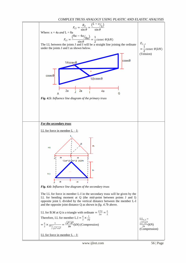
𝐹𝐶𝐼 =𝑅𝐴
sin 𝜃= 𝐿 − 𝑥
𝐿
sin𝜃
Where: x = 4a and L = 8a
𝐹𝐶𝐼 = 8𝑎 − 4𝑎
8𝑎
sin𝜃=
1
2𝑐𝑜𝑠𝑒𝑐 𝜃(𝑘𝑁)
The I.L between the joints J and I will be a straight line joining the ordinate
under the joints J and I as shown below.
Fig. 4.5: Influence line diagram of the primary truss
𝐹𝐶−𝐼
=1
2𝑐𝑜𝑠𝑒𝑐 𝜃(𝑘𝑁)
(Tension)
For the secondary truss
i. I.L for force in member L – I:
Fig. 4.6: Influence line diagram of the secondary truss
The I.L for force in member L-I in the secondary truss will be given by the
I.L for bending moment at Q (the mid-point between points J and I)
opposite joint L divided by the vertical distance between the member L-I
and the opposite joint distance Q as shown in fig. 4.7b above.
I.L for B.M at Q is a triangle with ordinate =𝑎×𝑎
2𝑎=
𝑎
2
Therefore, I.L for member L.I =𝑎
2×
1
𝑍𝑄
=𝑎
2×
1𝑎
𝑎2+2 =
𝒂𝟐+𝒉𝟐
𝟐𝒉(kN) (Compression)
ii. I.L for force in member L – I:
I.LL-I = a2+h2
2h(kN)
(Compression)
COMPLEX TRUSS ANALOGY USING PLASTIC AND ELASTIC ANALYSIS
www.ijlret.com 57 | Page
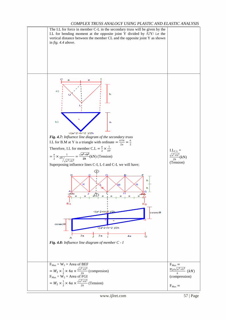
The I.L for force in member C-L in the secondary truss will be given by the
I.L for bending moment at the opposite joint Y divided by /UY/ i.e the
vertical distance between the member CL and the opposite joint Y as shown
in fig. 4.4 above.
Fig. 4.7: Influence line diagram of the secondary truss
I.L for B.M at Y is a triangle with ordinate =𝑎×𝑎
2𝑎=
𝑎
2
Therefore, I.L for member C.L =𝑎
2×
1
𝑈𝑌
=𝑎
2×
1𝑎
𝑎2+2 =
𝒂𝟐+𝒉𝟐
𝟐𝒉(kN) (Tension)
Superposing influence lines C-I, L-I and C-L we will have;
Fig. 4.8: Influence line diagram of member C - I
I.LC.L = a2+h2
2h(kN)
(Tension)
FMax = W2 × Area of BEF
= 𝑊2 ×1
2× 4𝑎 ×
𝑎2+2
2 (compresion)
FMax = W2 × Area of FGI
= 𝑊2 ×1
2× 4𝑎 ×
𝑎2+2
2 (Tension)
FMax =𝑊2𝑎 𝑎
2+2
(𝑘𝑁)
(compression)
FMax =
COMPLEX TRUSS ANALOGY USING PLASTIC AND ELASTIC ANALYSIS
www.ijlret.com 58 | Page
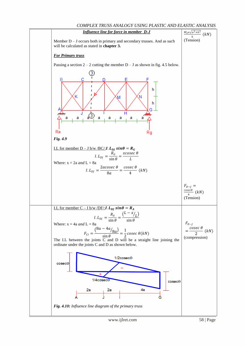
Influence line for force in member D-J
Member D – J occurs both in primary and secondary trusses. And as such
will be calculated as stated in chapter 3.
For Primary truss
Passing a section 2 – 2 cutting the member D – J as shown in fig. 4.5 below.
Fig. 4.9
a) I.L for member D – J b/w /BC/:𝑰.𝑳𝑫𝑱 𝒔𝒊𝒏𝜽 = 𝑹𝑮
𝐼. 𝐿𝐷𝐽 =𝑅𝐺
sin𝜃=𝑥𝑐𝑜𝑠𝑒𝑐 𝜃
𝐿
Where: x = 2a and L = 8a
𝐼. 𝐿𝐷𝐽 =2𝑎𝑐𝑜𝑠𝑒𝑐 𝜃
8𝑎=𝑐𝑜𝑠𝑒𝑐 𝜃
4 (𝑘𝑁)
𝑊2𝑎 𝑎2+2
(𝑘𝑁)
(Tension) 𝐹𝐷−𝐽 =𝑐𝑜𝑠𝑒𝑐𝜃
4 (𝑘𝑁)
(Tension)
b) I.L for member C – I b/w /DF/:𝑰.𝑳𝑫𝑱 𝒔𝒊𝒏𝜽 = 𝑹𝑨
𝐼. 𝐿𝐷𝐽 =𝑅𝐴
sin𝜃= 𝐿 − 𝑥
𝐿
sin 𝜃
Where: x = 4a and L = 8a
𝐹𝐶𝐼 = 8𝑎 − 4𝑎
8𝑎
sin𝜃=
1
2𝑐𝑜𝑠𝑒𝑐 𝜃(𝑘𝑁)
The I.L between the joints C and D will be a straight line joining the
ordinate under the joints C and D as shown below.
Fig. 4.10: Influence line diagram of the primary truss
𝐹𝐷−𝐽
=𝑐𝑜𝑠𝑒𝑐 𝜃
2 (𝑘𝑁)
(compression)
COMPLEX TRUSS ANALOGY USING PLASTIC AND ELASTIC ANALYSIS
www.ijlret.com 59 | Page
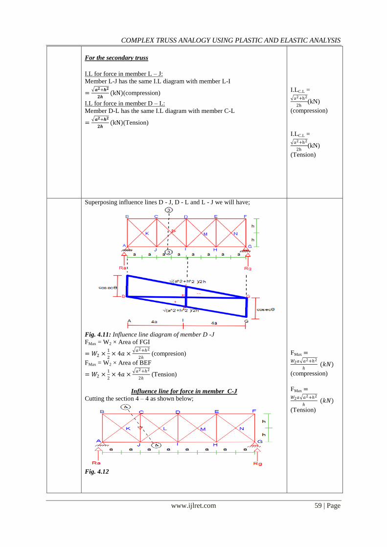
For the secondary truss
i. I.L for force in member L – J:
Member L-J has the same I.L diagram with member L-I
= 𝒂𝟐+𝒉𝟐
𝟐𝒉(kN)(compression)
ii. I.L for force in member D – L:
Member D-L has the same I.L diagram with member C-L
= 𝒂𝟐+𝒉𝟐
𝟐𝒉(kN)(Tension)
I.LC.L = a2+h2
2h(kN)
(compression)
I.LC.L = a2+h2
2h(kN)
(Tension)
Superposing influence lines D - J, D - L and L - J we will have;
Fig. 4.11: Influence line diagram of member D -J
FMax = W2 × Area of FGI
= 𝑊2 ×1
2× 4𝑎 ×
𝑎2+2
2 (compresion)
FMax = W2 × Area of BEF
= 𝑊2 ×1
2× 4𝑎 ×
𝑎2+2
2 (Tension)
Influence line for force in member C-J
Cutting the section 4 – 4 as shown below;
Fig. 4.12
FMax =𝑊2𝑎 𝑎
2+2
(𝑘𝑁)
(compression)
FMax =𝑊2𝑎 𝑎
2+2
(𝑘𝑁)
(Tension)
COMPLEX TRUSS ANALOGY USING PLASTIC AND ELASTIC ANALYSIS
www.ijlret.com 60 | Page
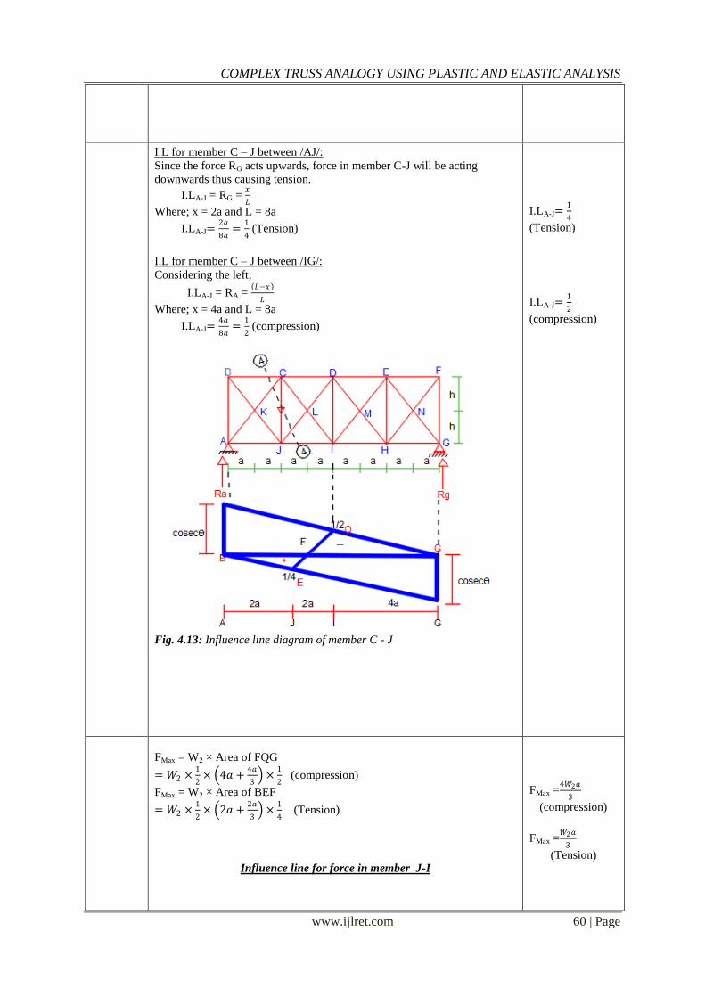
a) I.L for member C – J between /AJ/: Since the force RG acts upwards, force in member C-J will be acting
downwards thus causing tension.
I.LA-J = RG = 𝑥
𝐿
Where; x = 2a and L = 8a
I.LA-J=2𝑎
8𝑎=
1
4 (Tension)
b) I.L for member C – J between /IG/: Considering the left;
I.LA-J = RA = 𝐿−𝑥
𝐿
Where; x = 4a and L = 8a
I.LA-J=4𝑎
8𝑎=
1
2 (compression)
Fig. 4.13: Influence line diagram of member C - J
I.LA-J=1
4
(Tension)
I.LA-J=1
2
(compression)
FMax = W2 × Area of FQG
= 𝑊2 ×1
2× 4𝑎 +
4𝑎
3 ×
1
2 (compression)
FMax = W2 × Area of BEF
= 𝑊2 ×1
2× 2𝑎 +
2𝑎
3 ×
1
4 (Tension)
Influence line for force in member J-I
FMax =4𝑊2𝑎
3
(compression)
FMax =𝑊2𝑎
3
(Tension)
COMPLEX TRUSS ANALOGY USING PLASTIC AND ELASTIC ANALYSIS
www.ijlret.com 61 | Page
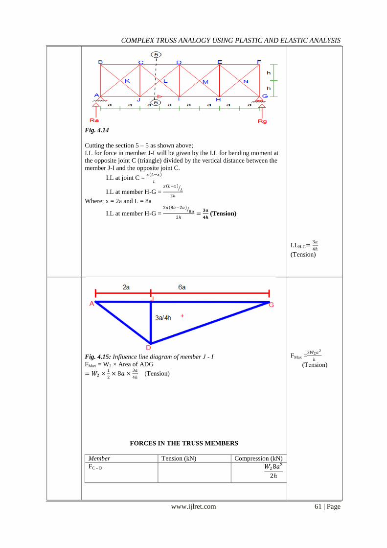
Fig. 4.14
Cutting the section 5 – 5 as shown above;
I.L for force in member J-I will be given by the I.L for bending moment at
the opposite joint C (triangle) divided by the vertical distance between the
member J-I and the opposite joint C.
I.L at joint C = 𝑥 𝐿−𝑥
𝐿
I.L at member H-G = 𝑥 𝐿−𝑥
𝐿
2
Where; x = 2a and L = 8a
I.L at member H-G = 2𝑎 8𝑎−2𝑎
8𝑎
2=
𝟑𝒂
𝟒𝒉 (Tension)
I.LH-G=3𝑎
4
(Tension)
Fig. 4.15: Influence line diagram of member J - I
FMax = W2 × Area of ADG
= 𝑊2 ×1
2× 8𝑎 ×
3𝑎
4 (Tension)
FORCES IN THE TRUSS MEMBERS
Member Tension (kN) Compression (kN)
FC – D
𝑊28𝑎2
2
FMax =3𝑊2𝑎
2
(Tension)
COMPLEX TRUSS ANALOGY USING PLASTIC AND ELASTIC ANALYSIS
www.ijlret.com 62 | Page
FC – I
𝑊2𝑎 𝑎
2 + 2
𝑊2𝑎 𝑎2 + 2
FD – J
𝑊2𝑎 𝑎
2 + 2
𝑊2𝑎 𝑎2 + 2
FC – J
𝑊2𝑎
3
4𝑊2𝑎
3
FJ – I
3𝑊2𝑎
2
Table 1
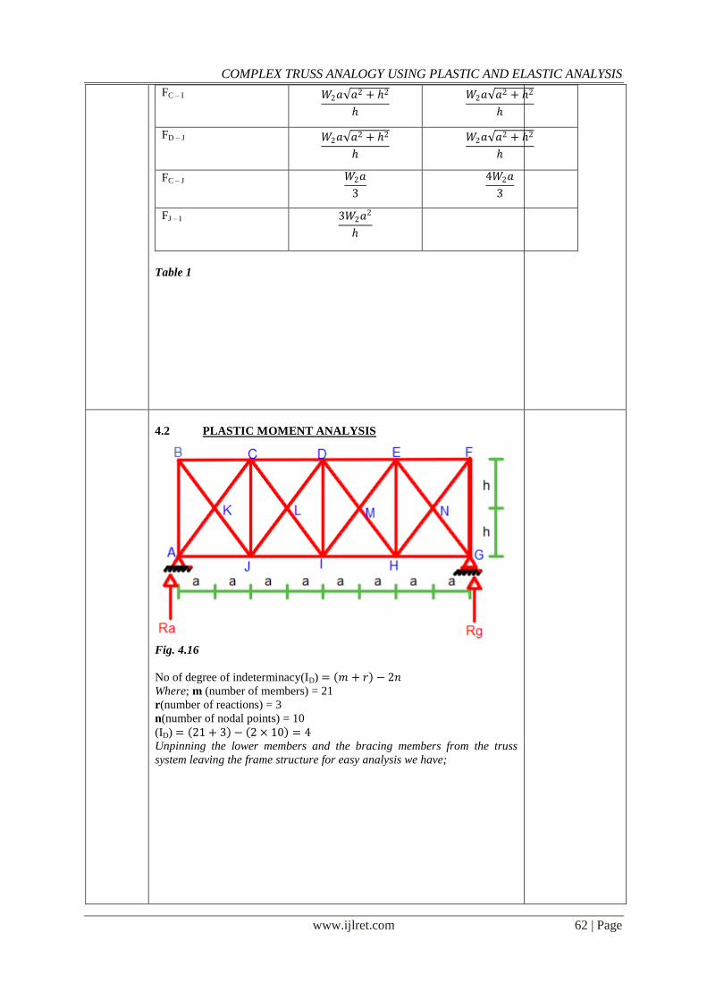
4.2 PLASTIC MOMENT ANALYSIS
Fig. 4.16
No of degree of indeterminacy(ID) = 𝑚 + 𝑟 − 2𝑛
Where; m (number of members) = 21
r(number of reactions) = 3
n(number of nodal points) = 10
(ID) = 21 + 3 − 2 × 10 = 4
Unpinning the lower members and the bracing members from the truss
system leaving the frame structure for easy analysis we have;
COMPLEX TRUSS ANALOGY USING PLASTIC AND ELASTIC ANALYSIS
www.ijlret.com 63 | Page
Fig.
4.17
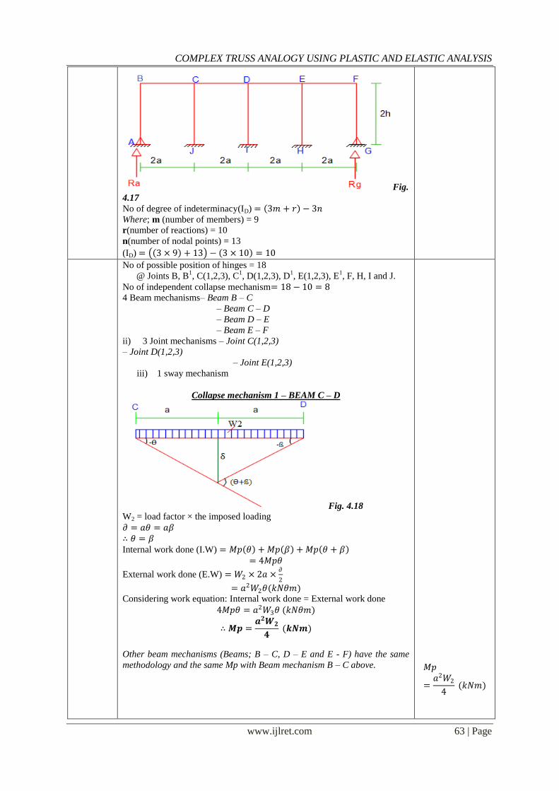
No of degree of indeterminacy(ID) = 3𝑚 + 𝑟 − 3𝑛
Where; m (number of members) = 9
r(number of reactions) = 10
n(number of nodal points) = 13
(ID) = 3 × 9 + 13 − 3 × 10 = 10
No of possible position of hinges = 18
@ Joints B, B1, C(1,2,3), C
1, D(1,2,3), D
1, E(1,2,3), E
1, F, H, I and J.
No of independent collapse mechanism= 18 − 10 = 8
a) 4 Beam mechanisms– Beam B – C
– Beam C – D
– Beam D – E
– Beam E – F
ii) 3 Joint mechanisms – Joint C(1,2,3)
– Joint D(1,2,3)
– Joint E(1,2,3)
iii) 1 sway mechanism
Collapse mechanism 1 – BEAM C – D
Fig. 4.18 W2 = load factor × the imposed loading
𝜕 = 𝑎𝜃 = 𝑎𝛽
∴ 𝜃 = 𝛽
Internal work done (I.W) = 𝑀𝑝 𝜃 + 𝑀𝑝 𝛽 + 𝑀𝑝 𝜃 + 𝛽 = 4𝑀𝑝𝜃
External work done (E.W) = 𝑊2 × 2𝑎 ×𝜕
2
= 𝑎2𝑊2𝜃(𝑘𝑁𝜃𝑚) Considering work equation: Internal work done = External work done
4𝑀𝑝𝜃 = 𝑎2𝑊3𝜃 (𝑘𝑁𝜃𝑚)
∴ 𝑴𝒑 =𝒂𝟐𝑾𝟐
𝟒 (𝒌𝑵𝒎)
Other beam mechanisms (Beams; B – C, D – E and E - F) have the same
methodology and the same Mp with Beam mechanism B – C above.
𝑀𝑝
=𝑎2𝑊2
4 (𝑘𝑁𝑚)
COMPLEX TRUSS ANALOGY USING PLASTIC AND ELASTIC ANALYSIS
www.ijlret.com 64 | Page
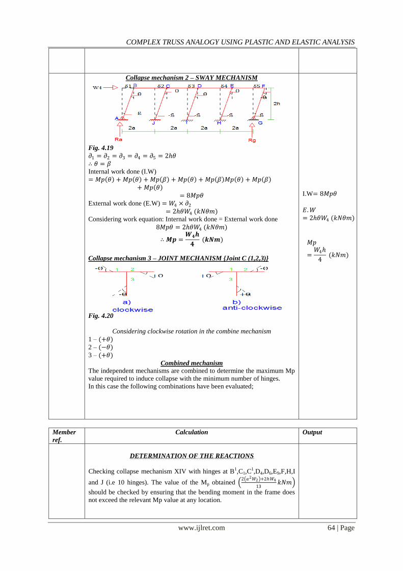
Collapse mechanism 2 – SWAY MECHANISM
Fig. 4.19
𝜕1 = 𝜕2 = 𝜕3 = 𝜕4 = 𝜕5 = 2𝜃
∴ 𝜃 = 𝛽
Internal work done (I.W)
= 𝑀𝑝 𝜃 + 𝑀𝑝 𝜃 + 𝑀𝑝 𝛽 + 𝑀𝑝 𝜃 + 𝑀𝑝 𝛽 𝑀𝑝 𝜃 + 𝑀𝑝 𝛽 + 𝑀𝑝 𝜃
= 8𝑀𝑝𝜃
External work done (E.W) = 𝑊4 × 𝜕2
= 2𝜃𝑊4 (𝑘𝑁𝜃𝑚) Considering work equation: Internal work done = External work done
8𝑀𝑝𝜃 = 2𝜃𝑊4 (𝑘𝑁𝜃𝑚)
∴ 𝑴𝒑 =𝑾𝟒𝒉
𝟒 (𝒌𝑵𝒎)
Collapse mechanism 3 – JOINT MECHANISM {Joint C (1,2,3)}
Fig. 4.20
Considering clockwise rotation in the combine mechanism
1 – (+𝜃)
2 – (−𝜃)
3 – (+𝜃)
Combined mechanism
The independent mechanisms are combined to determine the maximum Mp
value required to induce collapse with the minimum number of hinges.
In this case the following combinations have been evaluated;
I.W= 8𝑀𝑝𝜃 𝐸.𝑊= 2𝜃𝑊4 (𝑘𝑁𝜃𝑚)
𝑀𝑝
=𝑊4
4 (𝑘𝑁𝑚)
Member
ref. Calculation Output
DETERMINATION OF THE REACTIONS
Checking collapse mechanism XIV with hinges at B1,C1,C
1,D4,D6,E9,F,H,I
and J (i.e 10 hinges). The value of the Mp obtained 2 𝑎2𝑊2 +2𝑊4
13𝑘𝑁𝑚
should be checked by ensuring that the bending moment in the frame does
not exceed the relevant Mp value at any location.
COMPLEX TRUSS ANALOGY USING PLASTIC AND ELASTIC ANALYSIS
www.ijlret.com 65 | Page
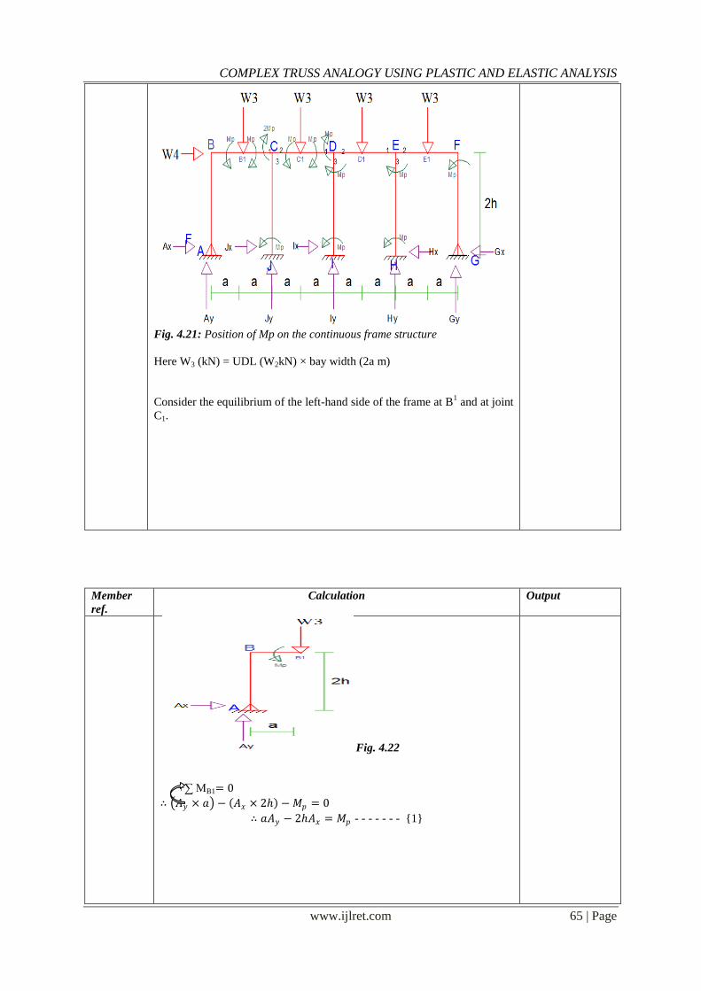
Fig. 4.21: Position of Mp on the continuous frame structure
Here W3 (kN) = UDL (W2kN) × bay width (2a m)
Consider the equilibrium of the left-hand side of the frame at B1 and at joint
C1.
Member
ref. Calculation Output
Fig. 4.22
+∑ MB1= 0
∴ 𝐴𝑦 × 𝑎 − 𝐴𝑥 × 2 − 𝑀𝑝 = 0
∴ 𝑎𝐴𝑦 − 2𝐴𝑥 = 𝑀𝑝 - - - - - - - {1}
COMPLEX TRUSS ANALOGY USING PLASTIC AND ELASTIC ANALYSIS
www.ijlret.com 66 | Page
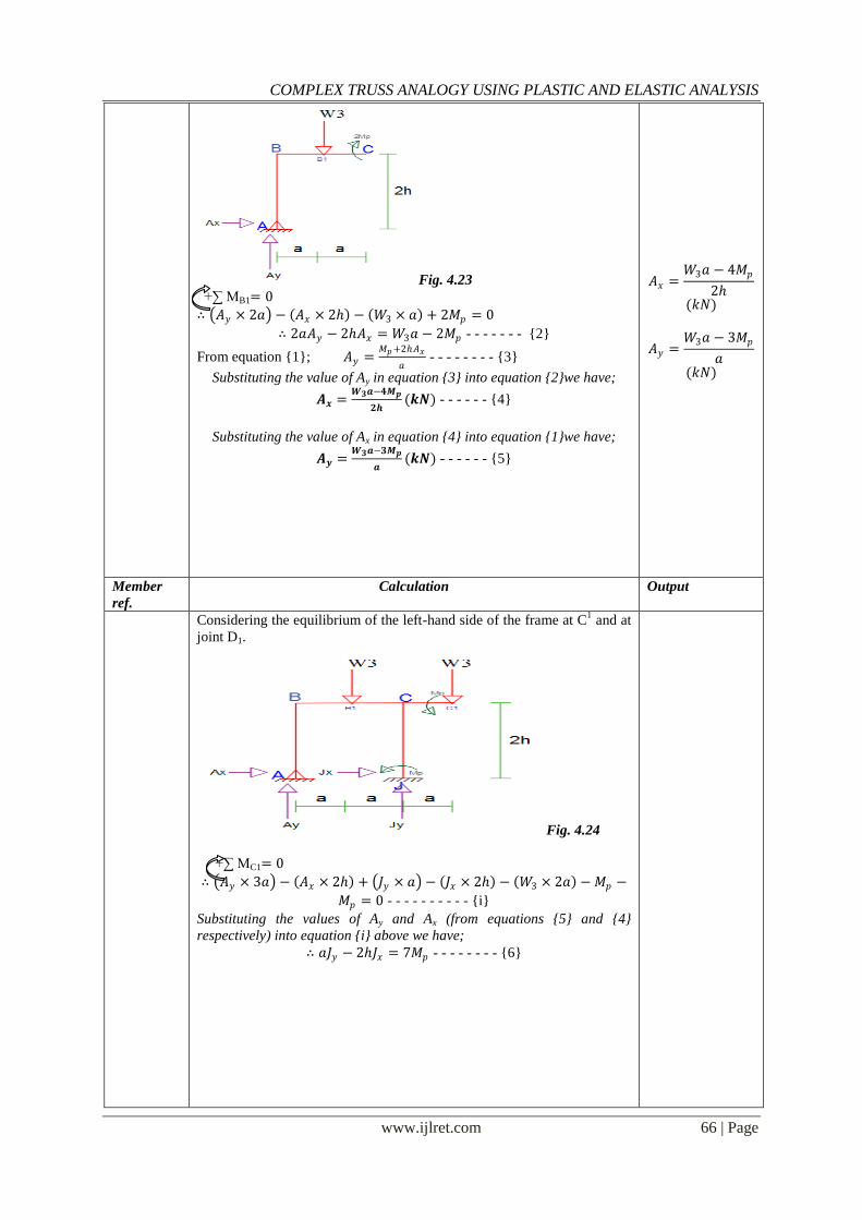
Fig. 4.23
+∑ MB1= 0
∴ 𝐴𝑦 × 2𝑎 − 𝐴𝑥 × 2 − 𝑊3 × 𝑎 + 2𝑀𝑝 = 0
∴ 2𝑎𝐴𝑦 − 2𝐴𝑥 = 𝑊3𝑎 − 2𝑀𝑝 - - - - - - - {2}
From equation {1}; 𝐴𝑦 =𝑀𝑝+2𝐴𝑥
𝑎 - - - - - - - - {3}
Substituting the value of Ay in equation {3} into equation {2}we have;
𝑨𝒙 =𝑾𝟑𝒂−𝟒𝑴𝒑
𝟐𝒉(𝒌𝑵) - - - - - - {4}
Substituting the value of Ax in equation {4} into equation {1}we have;
𝑨𝒚 =𝑾𝟑𝒂−𝟑𝑴𝒑
𝒂(𝒌𝑵) - - - - - - {5}
𝐴𝑥 =𝑊3𝑎 − 4𝑀𝑝
2
(𝑘𝑁)
𝐴𝑦 =𝑊3𝑎 − 3𝑀𝑝
𝑎
(𝑘𝑁)
Member
ref. Calculation Output
Considering the equilibrium of the left-hand side of the frame at C1 and at
joint D1.
Fig. 4.24
+∑ MC1= 0
∴ 𝐴𝑦 × 3𝑎 − 𝐴𝑥 × 2 + 𝐽𝑦 × 𝑎 − 𝐽𝑥 × 2 − 𝑊3 × 2𝑎 − 𝑀𝑝 −
𝑀𝑝 = 0 - - - - - - - - - - {i}
Substituting the values of Ay and Ax (from equations {5} and {4}
respectively) into equation {i} above we have;
∴ 𝑎𝐽𝑦 − 2𝐽𝑥 = 7𝑀𝑝 - - - - - - - - {6}
COMPLEX TRUSS ANALOGY USING PLASTIC AND ELASTIC ANALYSIS
www.ijlret.com 67 | Page
Fig.
4.25
+∑ MD1= 0
∴ 𝐴𝑦 × 4𝑎 − 𝐴𝑥 × 2 + 𝐽𝑦 × 2𝑎 − 𝐽𝑥 × 2 − 𝑊3 × 3𝑎 −
𝑊3 × 𝑎 − 𝑀𝑝 −𝑀𝑝 = 0 - - - - - - - - - - {ii}
Substituting the values of Ay and Ax (from equations {5} and {4}
respectively) into equation {ii} above we have;
∴ 2𝑎𝐽𝑦 − 2𝐽𝑥 = 𝑊3𝑎 + 8𝑀𝑝 - - - - - - - - {7}
Member
ref. Calculation Output
From equation {6}; 𝐽𝑦 =7𝑀𝑝+2𝐽𝑥
𝑎 - - - - - - - - {8}
Substituting the value of Jy in equation {8} into equation {7}we have;
𝑱𝒙 =𝑾𝟑𝒂−𝟔𝑴𝒑
𝟐𝒉(𝒌𝑵) - - - - - - {9}
Substituting the value of Jy in equation {9} into equation {8}we have;
𝑱𝒚 =𝑾𝟑𝒂+𝑴𝒑
𝒂(𝒌𝑵) - - - - - - {10}
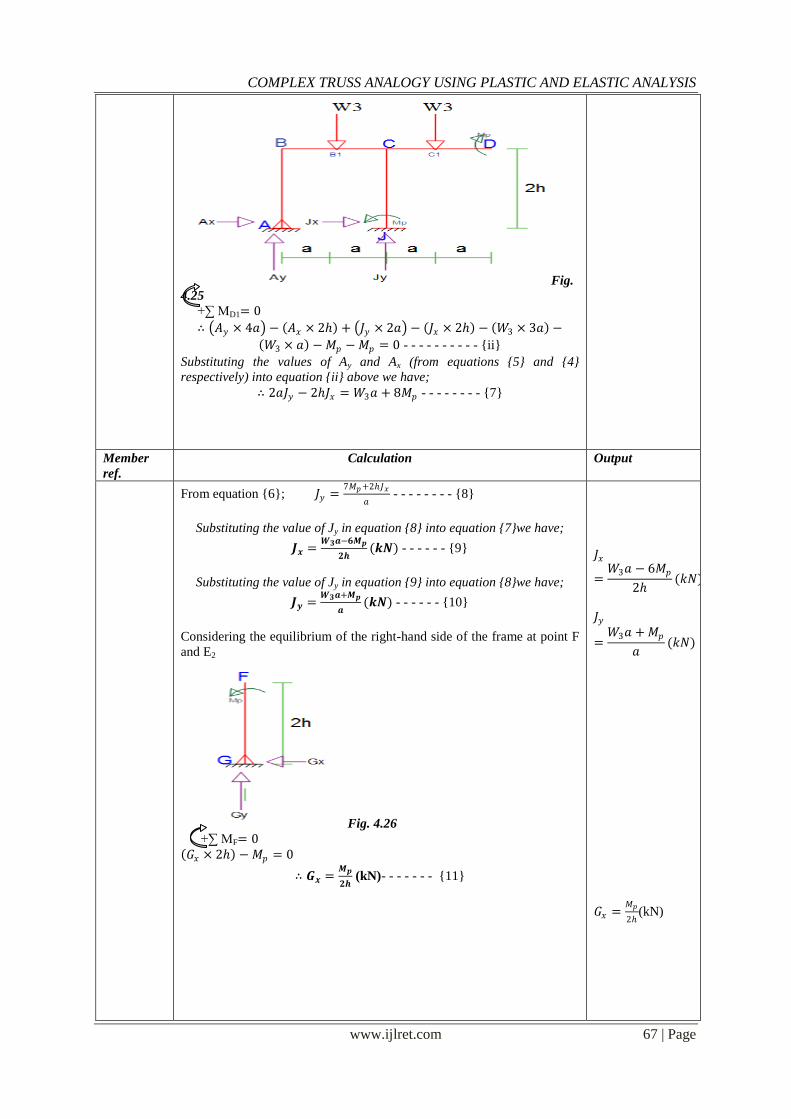
Considering the equilibrium of the right-hand side of the frame at point F
and E2
Fig. 4.26
+∑ MF= 0
𝐺𝑥 × 2 − 𝑀𝑝 = 0
∴ 𝑮𝒙 =𝑴𝒑
𝟐𝒉 (kN)- - - - - - - {11}
𝐽𝑥
=𝑊3𝑎 − 6𝑀𝑝
2(𝑘𝑁)
𝐽𝑦
=𝑊3𝑎 + 𝑀𝑝
𝑎(𝑘𝑁)
𝐺𝑥 =𝑀𝑝
2(kN)
COMPLEX TRUSS ANALOGY USING PLASTIC AND ELASTIC ANALYSIS
www.ijlret.com 68 | Page
Fig. 4.27
+∑ MB1= 0
𝐺𝑥 × 2 − 𝐺𝑦 × 2𝑎 − 𝑊3 × 𝑎 = 0
∴ 𝑮𝒚 =𝑾𝟑𝒂+𝑴𝒑
𝟐𝒂(𝒌𝑵) - - - - - - {12}
𝐺𝑦
=𝑊3𝑎 + 𝑀𝑝
2𝑎(𝑘𝑁)
Member
ref. Calculation Output
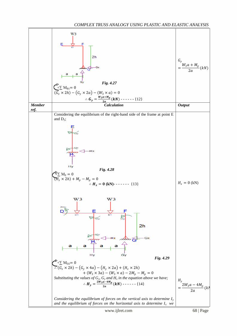
Considering the equilibrium of the right-hand side of the frame at point E
and D2;
Fig. 4.28 +∑ ME = 0
𝐻𝑥 × 2 + 𝑀𝑝 −𝑀𝑝 = 0
∴ 𝑯𝒙 = 𝟎 (kN)- - - - - - - {13}
Fig. 4.29
+∑ MD2= 0
∴ 𝐺𝑥 × 2 − 𝐺𝑦 × 4𝑎 − 𝐻𝑦 × 2𝑎 + 𝐻𝑥 × 2
+ 𝑊3 × 3𝑎 − 𝑊3 × 𝑎 − 2𝑀𝑝 −𝑀𝑝 = 0
Substituting the values of Gx, Gy and Hx in the equation above we have;
∴ 𝑯𝒚 =𝟐𝑾𝟑𝒂−𝟒𝑴𝒑
𝟐𝒂(𝒌𝑵) - - - - - - {14}
Considering the equilibrium of forces on the vertical axis to determine Iy
and the equilibrium of forces on the horizontal axis to determine Ix we
𝐻𝑥 = 0 (kN) 𝐻𝑦
=2𝑊3𝑎 − 4𝑀𝑝
2𝑎(𝑘𝑁)
COMPLEX TRUSS ANALOGY USING PLASTIC AND ELASTIC ANALYSIS
www.ijlret.com 69 | Page
have;
Member
ref. Calculation Output
+∑ Fy = 0 𝐴𝑦 + 𝐽𝑦 + 𝐼𝑦 + 𝐻𝑦 + 𝐺𝑦 = 4 𝑊3
Substituting the values of 𝐴𝑦 , 𝐽𝑦 ,𝐻𝑦𝑎𝑛𝑑𝐺𝑦 as gotten above into the
equation we have;
∴ 𝑰𝒚 =𝑾𝟑𝒂+𝟕𝑴𝒑
𝟐𝒂(𝒌𝑵) - - - - - - {15}
+∑ FX = 0 𝐴𝑥 + 𝐽𝑥 + 𝐼𝑥 − 𝐻𝑥 − 𝐺𝑥 + 𝑊4 = 0 Substituting the values of 𝐴𝑥 , 𝐽𝑥 ,𝐻𝑥𝑎𝑛𝑑𝐺𝑥 as gotten above into the
equation we have;
∴ 𝑰𝒙 =𝟏𝟏𝑴𝒑−𝟐𝑾𝟑𝒂−𝟐𝑾𝟒𝒉
𝟐𝒉(𝒌𝑵) - - - - - - {16}
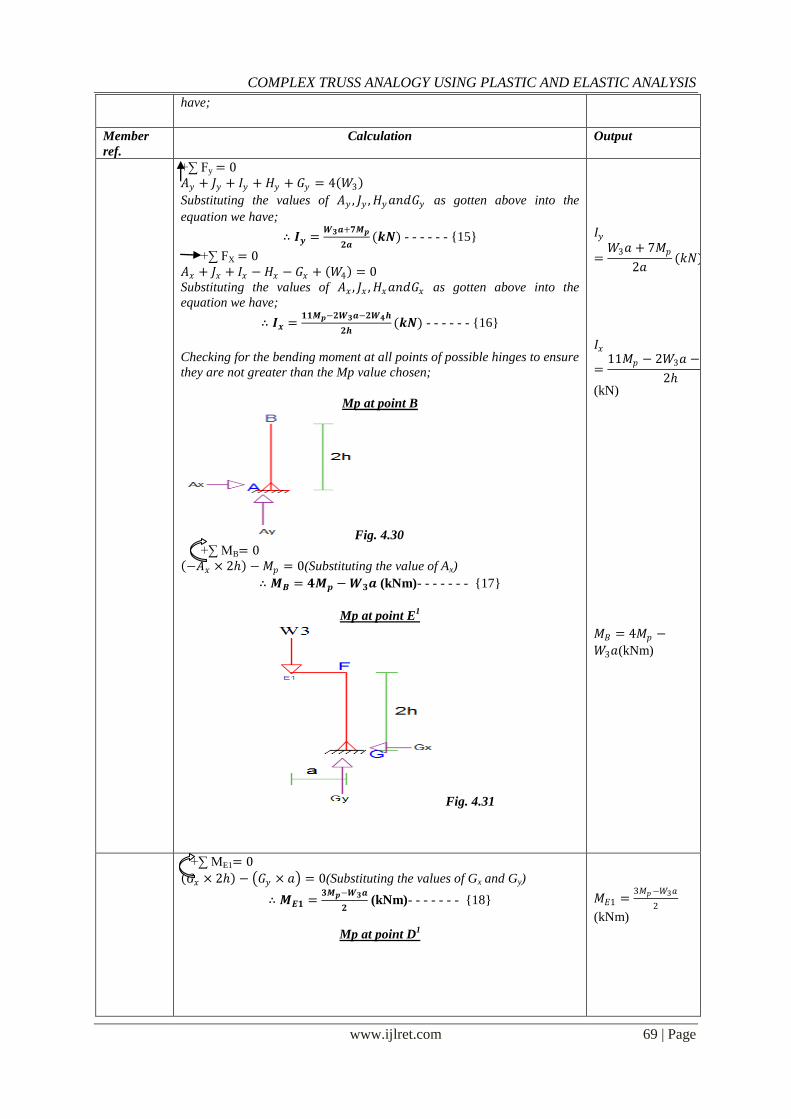
Checking for the bending moment at all points of possible hinges to ensure
they are not greater than the Mp value chosen;
Mp at point B
Fig. 4.30
+∑ MB= 0
−𝐴𝑥 × 2 −𝑀𝑝 = 0(Substituting the value of Ax)
∴ 𝑴𝑩 = 𝟒𝑴𝒑 −𝑾𝟑𝒂 (kNm)- - - - - - - {17}
Mp at point E1
Fig. 4.31
𝐼𝑦
=𝑊3𝑎 + 7𝑀𝑝
2𝑎(𝑘𝑁)
𝐼𝑥
=11𝑀𝑝 − 2𝑊3𝑎 − 2𝑊4
2
(kN)
𝑀𝐵 = 4𝑀𝑝 −
𝑊3𝑎(kNm)
+∑ ME1= 0
𝐺𝑥 × 2 − 𝐺𝑦 × 𝑎 = 0(Substituting the values of Gx and Gy)
∴ 𝑴𝑬𝟏 =𝟑𝑴𝒑−𝑾𝟑𝒂
𝟐 (kNm)- - - - - - - {18}
Mp at point D1
𝑀𝐸1 =3𝑀𝑝−𝑊3𝑎
2
(kNm)
COMPLEX TRUSS ANALOGY USING PLASTIC AND ELASTIC ANALYSIS
www.ijlret.com 70 | Page
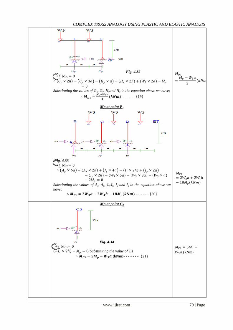
Fig. 4.32
+∑ MD1= 0
∴ 𝐺𝑥 × 2 − 𝐺𝑦 × 3𝑎 − 𝐻𝑦 × 𝑎 + 𝐻𝑥 × 2 + 𝑊3 × 2𝑎 −𝑀𝑝
= 0 Substituting the values of Gx, Gy, Hyand Hx in the equation above we have;
∴ 𝑴𝑫𝟏 =𝑴𝒑−𝑾𝟑𝒂
𝟐(𝒌𝑵𝒎) - - - - - - {19}
Mp at point E1
Fig. 4.33
+∑ ME7= 0
∴ 𝐴𝑦 × 6𝑎 − 𝐴𝑥 × 2 + 𝐽𝑦 × 4𝑎 − 𝐽𝑥 × 2 + 𝐼𝑦 × 2𝑎
− 𝐼𝑥 × 2 − 𝑊3 × 5𝑎 − 𝑊3 × 3𝑎 − 𝑊3 × 𝑎 − 2𝑀𝑝 = 0
Substituting the values of Ax, Ay, Jy,Jx, Iy and Ix in the equation above we
have;
∴ 𝑴𝑬𝟏 = 𝟐𝑾𝟑𝒂 + 𝟐𝑾𝟒𝒉 − 𝟏𝟖𝑴𝒑(𝒌𝑵𝒎) - - - - - - {20}
𝑀𝐷1
=𝑀𝑝 −𝑊3𝑎
2(𝑘𝑁𝑚)
𝑀𝐸7
= 2𝑊3𝑎 + 2𝑊4− 18𝑀𝑝(𝑘𝑁𝑚)
Mp at point C3
Fig. 4.34 +∑ MC3= 0
−𝐽𝑥 × 2 − 𝑀𝑝 = 0(Substituting the value of Jx)
∴ 𝑴𝑪𝟑 = 𝟓𝑴𝒑 −𝑾𝟑𝒂 (kNm)- - - - - - - {21}
𝑀𝐶3 = 5𝑀𝑝 −
𝑊3𝑎 (kNm)
COMPLEX TRUSS ANALOGY USING PLASTIC AND ELASTIC ANALYSIS
www.ijlret.com 71 | Page
Member
ref. Calculation Output
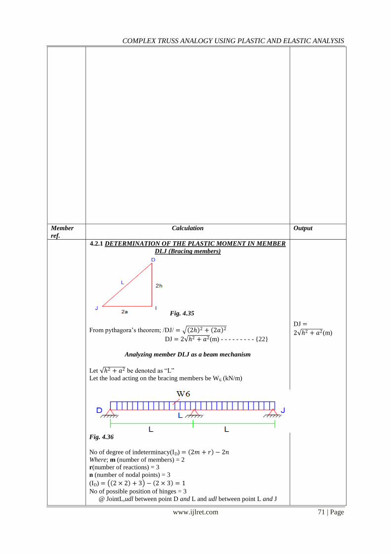
4.2.1 DETERMINATION OF THE PLASTIC MOMENT IN MEMBER
DLJ (Bracing members)
Fig. 4.35
From pythagora‟s theorem; /DJ/ = 2 2 + 2𝑎 2
DJ = 2 2 + 𝑎2(m) - - - - - - - - - {22}
Analyzing member DLJ as a beam mechanism
Let 2 + 𝑎2 be denoted as “L”
Let the load acting on the bracing members be W6 (kN/m)
Fig. 4.36
No of degree of indeterminacy(ID) = 2𝑚 + 𝑟 − 2𝑛
Where; m (number of members) = 2
r(number of reactions) = 3
n (number of nodal points) = 3
(ID) = 2 × 2 + 3 − 2 × 3 = 1
No of possible position of hinges = 3
@ JointL,udl between point D and L and udl between point L and J
DJ =
2 2 + 𝑎2(m)
COMPLEX TRUSS ANALOGY USING PLASTIC AND ELASTIC ANALYSIS
www.ijlret.com 72 | Page
No of independent collapse mechanism= 3 − 1 = 2
Beam mechanisms– Beam B – C and
– Beam C – D
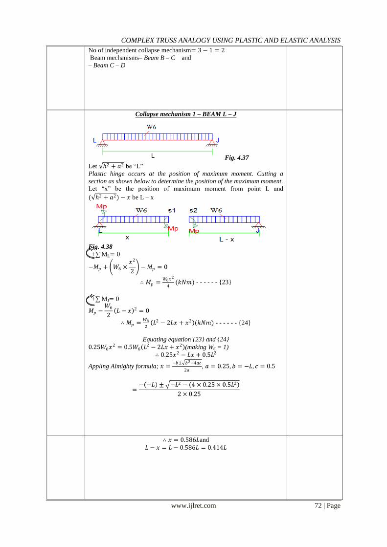
Collapse mechanism 1 – BEAM L – J
Fig. 4.37
Let 2 + 𝑎2 be “L”
Plastic hinge occurs at the position of maximum moment. Cutting a
section as shown below to determine the position of the maximum moment.
Let “x” be the position of maximum moment from point L and
( 2 + 𝑎2) − 𝑥 be L – x
Fig. 4.38
+∑ ML= 0
−𝑀𝑝 + 𝑊6 ×𝑥2
2 −𝑀𝑝 = 0
∴ 𝑀𝑝 =𝑊6𝑥
2
4(𝑘𝑁𝑚) - - - - - - {23}
+∑ MJ= 0
𝑀𝑝 −𝑊6
2 𝐿 − 𝑥 2 = 0
∴ 𝑀𝑝 =𝑊6
2 𝐿2 − 2𝐿𝑥 + 𝑥2 (𝑘𝑁𝑚) - - - - - - {24}
Equating equation {23} and {24}
0.25𝑊6𝑥2 = 0.5𝑊6 𝐿
2 − 2𝐿𝑥 + 𝑥2 (making W6 = 1)
∴ 0.25𝑥2 − 𝐿𝑥 + 0.5𝐿2
Appling Almighty formula; 𝑥 =−𝑏± 𝑏2−4𝑎𝑐
2𝑎, 𝑎 = 0.25, 𝑏 = −𝐿, 𝑐 = 0.5
=− −𝐿 ± −𝐿2 − 4 × 0.25 × 0.5𝐿2
2 × 0.25
∴ 𝑥 = 0.586𝐿and 𝐿 − 𝑥 = 𝐿 − 0.586𝐿 = 0.414𝐿
COMPLEX TRUSS ANALOGY USING PLASTIC AND ELASTIC ANALYSIS
www.ijlret.com 73 | Page
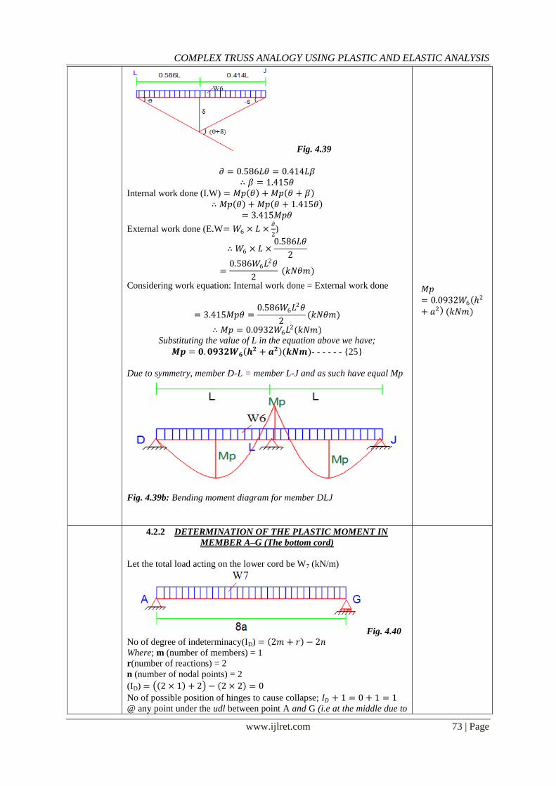
Fig. 4.39
𝜕 = 0.586𝐿𝜃 = 0.414𝐿𝛽
∴ 𝛽 = 1.415𝜃 Internal work done (I.W) = 𝑀𝑝 𝜃 + 𝑀𝑝 𝜃 + 𝛽
∴ 𝑀𝑝 𝜃 + 𝑀𝑝 𝜃 + 1.415𝜃 = 3.415𝑀𝑝𝜃
External work done (E.W= 𝑊6 × 𝐿 ×𝜕
2)
∴ 𝑊6 × 𝐿 ×0.586𝐿𝜃
2
=0.586𝑊6𝐿
2𝜃
2 (𝑘𝑁𝜃𝑚)
Considering work equation: Internal work done = External work done
= 3.415𝑀𝑝𝜃 =0.586𝑊6𝐿
2𝜃
2(𝑘𝑁𝜃𝑚)
∴ 𝑀𝑝 = 0.0932𝑊6𝐿2(𝑘𝑁𝑚)
Substituting the value of L in the equation above we have;
𝑴𝒑 = 𝟎.𝟎𝟗𝟑𝟐𝑾𝟔 𝒉𝟐 + 𝒂𝟐 (𝒌𝑵𝒎)- - - - - - {25}
Due to symmetry, member D-L = member L-J and as such have equal Mp
Fig. 4.39b: Bending moment diagram for member DLJ
𝑀𝑝= 0.0932𝑊6
2
+ 𝑎2 (𝑘𝑁𝑚)
4.2.2 DETERMINATION OF THE PLASTIC MOMENT IN
MEMBER A–G (The bottom cord)
Let the total load acting on the lower cord be W7 (kN/m)
Fig. 4.40
No of degree of indeterminacy(ID) = 2𝑚 + 𝑟 − 2𝑛
Where; m (number of members) = 1
r(number of reactions) = 2
n (number of nodal points) = 2
(ID) = 2 × 1 + 2 − 2 × 2 = 0
No of possible position of hinges to cause collapse; 𝐼𝐷 + 1 = 0 + 1 = 1
@ any point under the udl between point A and G (i.e at the middle due to
COMPLEX TRUSS ANALOGY USING PLASTIC AND ELASTIC ANALYSIS
www.ijlret.com 74 | Page
udl and no moment at the end reactions)
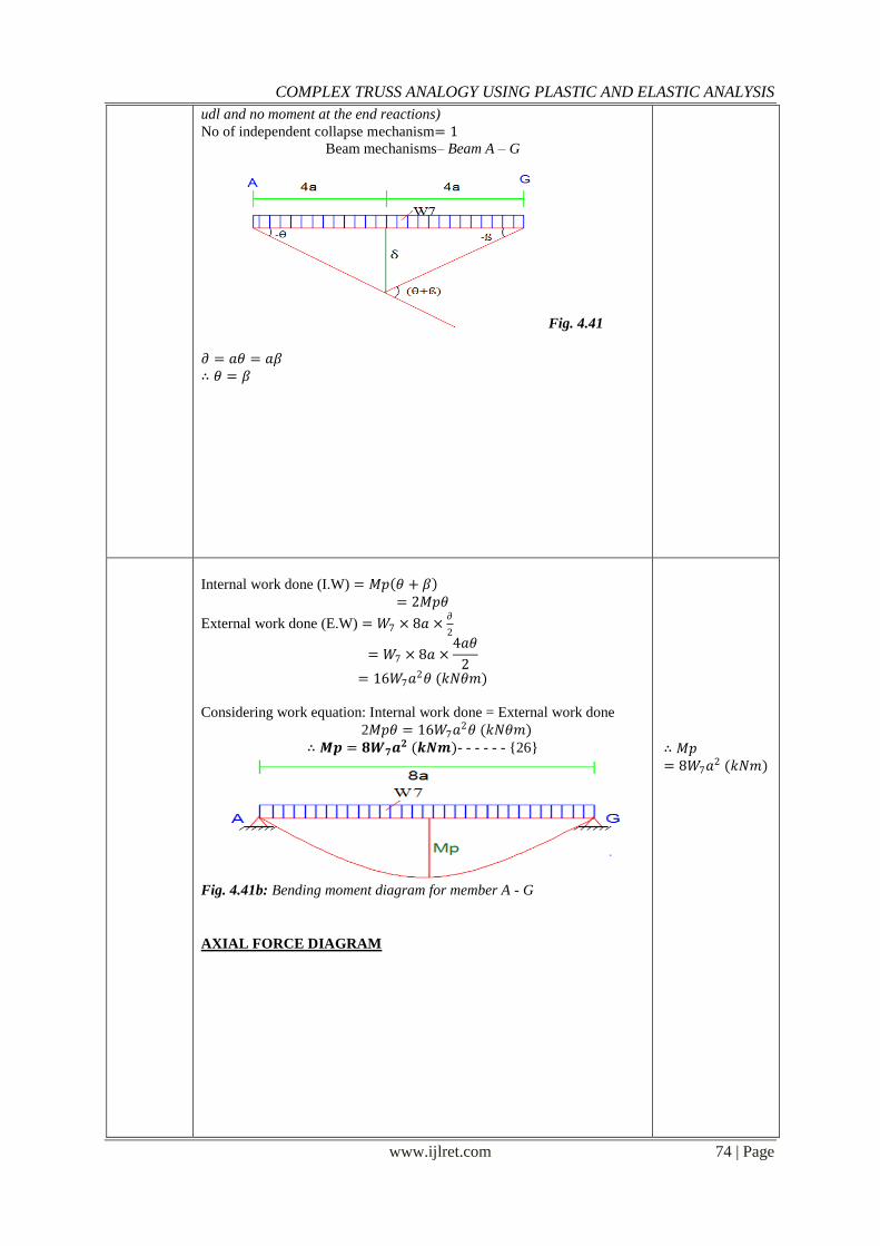
No of independent collapse mechanism= 1
Beam mechanisms– Beam A – G
Fig. 4.41 𝜕 = 𝑎𝜃 = 𝑎𝛽
∴ 𝜃 = 𝛽
Internal work done (I.W) = 𝑀𝑝 𝜃 + 𝛽 = 2𝑀𝑝𝜃
External work done (E.W) = 𝑊7 × 8𝑎 ×𝜕
2
= 𝑊7 × 8𝑎 ×4𝑎𝜃
2
= 16𝑊7𝑎2𝜃 (𝑘𝑁𝜃𝑚)
Considering work equation: Internal work done = External work done
2𝑀𝑝𝜃 = 16𝑊7𝑎2𝜃 (𝑘𝑁𝜃𝑚)
∴ 𝑴𝒑 = 𝟖𝑾𝟕𝒂𝟐 (𝒌𝑵𝒎)- - - - - - {26}
Fig. 4.41b: Bending moment diagram for member A - G AXIAL FORCE DIAGRAM
∴ 𝑀𝑝= 8𝑊7𝑎
2 (𝑘𝑁𝑚)
COMPLEX TRUSS ANALOGY USING PLASTIC AND ELASTIC ANALYSIS
www.ijlret.com 75 | Page
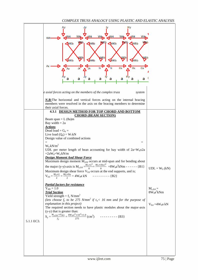
Fig. 4.42: The axial forces acting on the members of the complex truss system
N.B:The horizontal and vertical forces acting on the internal bracing
members were resolved in the axis on the bracing members to determine
their axial forces.
5.1.1 EC3.
4.3.1 DESIGN METHOD FOR TOP CHORD AND BOTTOM
CHORD (BEAM SECTION)
Beam span = L (8a)m
Bay width = 2a
Actions
Dead load = Gk =
Live load (Qk) = W7kN
Design value of combined actions
= =
W8 kN/m2
UDL per meter length of bean accounting for bay width of 2a=W8x2a
=2aW8=W9 kN/m
Design Moment And Shear Force
Maximum design moment MyEd occurs at mid-span and for bending about
the major (y-y)-axis is My,Ed =𝑊9×𝐿2
8=
𝑊9× 8𝑎 2
8 =8W9a
2kNm - - - - - - {B1}
Maximum design shear force VEd occurs at the end supports, and is;
VEd = 𝑊9×𝐿
2 =
𝑊9×8𝑎
2 = 4W9a kN - - - - - - - - - {B2}
Partial factors for resistance
YM0 = 1.0
Trial Section
Yield strength = fy N/mm2
(lets choose fy to be 275 N/mm2 if tw< 16 mm and for the purpose of
explanation in this project)
The required section needs to have plastic modules about the major-axis
(y-y) that is greater than:
Sy = My ,Ed ×ƳM 0
𝑓𝑦 =
8W9a2×103×1.0
275 (cm
3) - - - - - - - - - {B3}
UDL = W9 (kN)
My,Ed =
8W9a2kNm
VEd =4W9a kN
COMPLEX TRUSS ANALOGY USING PLASTIC AND ELASTIC ANALYSIS
www.ijlret.com 76 | Page
Sx =8W9a2×103×1.0
275
(cm3)
3.2.6 (1)
Table 5.3.1
of
EC3
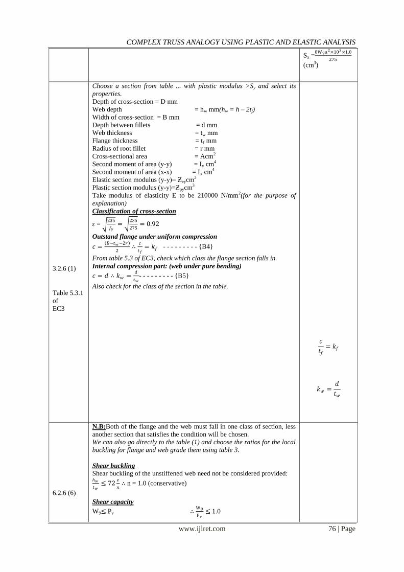
Choose a section from table ... with plastic modulus >Sy and select its
properties.
Depth of cross-section = D mm
Web depth = hw mm(hw = h – 2tf)
Width of cross-section = B mm
Depth between fillets = d mm
Web thickness = tw mm
Flange thickness = tf mm
Radius of root fillet = r mm
Cross-sectional area = Acm2
Second moment of area (y-y) = Iy cm4
Second moment of area (x-x) = Ix cm4
Elastic section modulus (y-y)= Ƶeycm3
Plastic section modulus (y-y)=Ƶpycm3
Take modulus of elasticity E to be 210000 N/mm2(for the purpose of
explanation)
Classification of cross-section
ԑ = 235
𝑓𝑦=
235
275= 0.92
Outstand flange under uniform compression
𝑐 = 𝐵−𝑡𝑤−2𝑟
2∴
𝑐
𝑡𝑓= 𝑘𝑓 - - - - - - - - - {B4}
From table 5.3 of EC3, check which class the flange section falls in.
Internal compression part: (web under pure bending)
𝑐 = 𝑑 ∴ 𝑘𝑤 =𝑑
𝑡𝑤- - - - - - - - - {B5}
Also check for the class of the section in the table.
𝑐
𝑡𝑓= 𝑘𝑓
𝑘𝑤 =𝑑
𝑡𝑤
6.2.6 (6)
N.B:Both of the flange and the web must fall in one class of section, less
another section that satisfies the condition will be chosen.
We can also go directly to the table (1) and choose the ratios for the local
buckling for flange and web grade them using table 3.
Shear buckling Shear buckling of the unstiffened web need not be considered provided: 𝑤
𝑡𝑤≤ 72
𝑒
𝑛∴ n = 1.0 (conservative)
Shear capacity
W9≤ Pv ∴W9
Pv≤ 1.0
COMPLEX TRUSS ANALOGY USING PLASTIC AND ELASTIC ANALYSIS
www.ijlret.com 77 | Page
6.2.6 (1)
6.2.6 (2)
6.2.5 (1)
6.2.5 (2)
6.2.8 (2)
6.2.5 (2)
Where;𝑃𝑣 =𝐴𝑣
𝑓𝑦 3
Ƴ𝑀0or 0.9fyAv
Av = shear area = tw × D
∴ Pv = 0.6fytwD - - - - - - - - {B6}
If W9<Pv, then shear capacity is adequate
Moment resistance
The design requirement is: 𝑀𝐸𝑑
𝑀𝑐 ,𝑅𝑑≤ 1.0
𝑀𝑐 ,𝑅𝑑 = 𝑀𝑝𝑙 ,𝑅𝑑 =𝑆𝑥×𝑓𝑦
Ƴ𝑀0- - - - - - - - - {B7}
At the point of maximum bending moment the shaer force is zero.
Therefore the bending resistance does not need to be reduced due to the
presence of shear.
∴ 𝑀𝑐 ,𝑅𝑑 =𝑆𝑥×𝑓𝑦
Ƴ𝑀0 - - - - - - - - - {B8}
If MEd≤ Mc,Rd then the design bending resistance of the section is
adequate.
𝑀𝑝𝑙 ,𝑅𝑑 =𝑆𝑥 × 𝑓𝑦
Ƴ𝑀0
𝑀𝑐 ,𝑅𝑑 =𝑆𝑥 × 𝑓𝑦
Ƴ𝑀0
BS EN
1993-1-1
NA 2.23
Web bearing and buckling
Pbw = (b1 + nk)twfy - - - - - - - - - {B9}
b1=t + 1.6r + 2tf
k = tf+r
At the end of a member (support)
𝑛 = 2 + 0.6𝑏𝑒
𝑘 but n ≤5 be =0
If W9< Pbwthen, bearing capacity at support is adequate
Serviceability deflection check
Vertical deflection at the mid-span of the beam is determined as:
𝜕 = 5L4W
384𝐸𝐼 - - - - - - - - - {B10}
=5 × 8𝑎 × 103 × 𝑊3 × 2𝑎
384 × 𝐸 × 𝐼
Vertical deflection limit of the beam = 𝑠𝑝𝑎𝑛
360=
8𝑎×103
360= V
If 𝜕< V then the vertical deflection of the section is satisfactory.
Pbw = (b1 + nk)twfy
𝜕 = 5L4W
384𝐸𝐼
V= 𝑠𝑝𝑎𝑛
360
COMPLEX TRUSS ANALOGY USING PLASTIC AND ELASTIC ANALYSIS
www.ijlret.com 78 | Page
6.1(1)
NA 2.15
4.3.2 DESIGN OF VERTICAL MEMBERS (COLUMNS/STRUTS)
(COMPRESSION MEMBERS)
Moment = M
Sy = M
fy (cm
3) where;fy = 275 N/mm
2
Data
Axial force = N
Design moment (Mi)= 𝑀
2- - - - - - - - - {C1}
Partial factors for resistance ƳM0 = 1.05
ƳM1 = 1.0
Trial section Initial trial section is selected to give a suitable moment capacity. The size
is then checked to ensure suitability in all other aspects.
Choose a section from table… with plastic modulus >Syand select its
properties.
Section Properties
Depth of cross-section = D mm
Width of cross-section = B mm
Depth between fillets = d mm
Web thickness = tw mm
Flange thickness = tf mm
Cross-sectional area = Acm2
Second moment of area (y-y) = Iy cm4
Elastic section modulus (y-y) = Ƶeycm3
Plastic section modulus (y-y)=Ƶpycm3
Sy = M
fy (cm
3)
Mi= 𝑀
2
SN048a-
In-plane failure about major axis
Members subject to axial compression and major axis bending must
COMPLEX TRUSS ANALOGY USING PLASTIC AND ELASTIC ANALYSIS
www.ijlret.com 79 | Page
EN- GB
Access
Steel
document
satisfy. 𝑁
𝑁𝑏 .𝑦 .𝑅𝑑+
𝑘𝑦𝑀𝑖𝑦
𝑛𝑀𝑐 .𝑦 .𝑅𝑑≤ 1.0 - - - - - - - - - {C5}
𝑁𝑏 .𝑦 .𝑅𝑑 =𝐵𝐴𝑓𝑐𝐴
Ƴ𝑀1 - - - - - - - - - {C6}
Mc.y.Rd = Moment capacity of column (gotten above).
But: Iy = 0.85L (Restrained about both axis)
= 0.85 × 2h × 103 = 1.7h × 10
3and
Slenderness ratio: 𝜆𝑦 =𝐼𝑦
𝑖𝑦- - - - - - - - - {C7}
Buckling about y-y axis (curve b)
BA = 1
𝜆𝑦 𝐵𝐴 ≤ 𝑡𝑓
Interpolate (from table…) where necessary to get the value of fc then
substitute in equation C6.
ky = 1.5 (conservative value)
𝑛 =Ƴ𝑀0
Ƴ𝑀1
= 1
Substitute values in equation C5
If the condition is satisfied then, the section has sufficient resistance
against in plane failure against major axis.
𝑁
𝑁𝑏 .𝑦 .𝑅𝑑
+𝑘𝑦𝑀𝑖𝑦
𝑛𝑀𝑐 .𝑦 .𝑅𝑑
≤ 1.0
Iy = 1.7h × 10
3
𝜆𝑦 =𝐼𝑦
𝑖𝑦
𝑛 =Ƴ𝑀0
Ƴ𝑀1
= 1
PUnless
stated
otherwise
all
references
are
to BS EN
1993-1-1
4.3.3 DESIGN OF BRACING AND BRACING CONNECTIONS
Design summary:
(a) The wind loading at each beam is transferred to two vertically braced
end bays on grid lines „A‟ and „J‟ by the beams acting as diaphragms.
(b) The bracing system must carry the equivalent horizontal forces(EHF)
in addition to the wind loads.
(c) Locally, the bracing must carry additional loads due to imperfections at
splices (cl 5.3.3(4)) and restraint forces (cl5.3.2(5)). These imperfections
are considered in turn inconjunction with external lateral loads but not at
the same time as the EHF.
(d) The braced bays, acting as vertical pin-jointed frames, transfer the
horizontal wind load to the ground.
(e) The beams and columns that make up the bracing system have already
been designed for gravity loads1). Therefore, only the diagonal members
have to be designed and only the forces in these members have to be
calculated.
COMPLEX TRUSS ANALOGY USING PLASTIC AND ELASTIC ANALYSIS
www.ijlret.com 80 | Page
BS EN
1991-1-4
BS EN
1990
NA 2.2.3.2
Table
NA.A1.2(B
)
(f) All the diagonal members are of the same section, thus, only the most
heavily loaded member has to be designed.
Forces in the bracing system
Let the total overall un-factored wind load be W11 (kN)
W11 × tan-1
2
2𝑎 = W11b
With two braced bays, total un-factored load to be resisted by each
braced bay = 0.5 × W11b = W12 (kN) - - - - - - - - - - - {D1}
Ultimate Limit State (ULS)
Partial factors for actions
Partial factor for permanent actions ƳG= 1.35
Partial factor for variable actions ƳQ = 1.5
Reduction factor 0.925 =ڠ
Reg no – 2010224929Designed by –Onunkwo Raphael C.
Date – 24/09/2015Sheet No - 37
Member
ref. Calculation Output
NA 2.15
BS EN
1993-
1-8
NA 2.3
Table
NA.1
Design wind load at ULS
Using Equation 6.10b in EC3 1990 with wind as the leading variable action,
the design wind load per braced bay is:
W13 (kN)= 1.5 × W12kN - - - - - - - - - - - {D2}
Horizontal component of force in bracing member = 1.5W12 (kN)
Vertical component of force in bracing member
=1.5𝑊12
2𝑎× 2 =
3𝑊12
2𝑎 (𝑘𝑁)
Axial force in bracing (N) = 1.5𝑊12 2 +
3𝑊12
2𝑎
2
- - - - - {D3}
Partial factors for resistance
ƳM0 = 1.0
ƳM1 = 1.0
ƳM2 =1.25 (for bolts and welds)
Trial section Choose a trial section from table 3 in appendix and select their properties.
Section properties Area = A cm²
Second moment of area = I cm4
Radius of gyration = i cm
Thickness = t = 10.0 mm
Ratio for local Buckling = d /t
COMPLEX TRUSS ANALOGY USING PLASTIC AND ELASTIC ANALYSIS
www.ijlret.com 81 | Page
NA 2.4
BS EN
10210-1
Table A3
Table
5.3.1 6.2.4(1)
Eq. 6.9
6.2.4(2)
Eq. 6.10
6.3.1.1(1)
Eq. 6.46
Material properties
Steel grade = S355
Ift ≤ 16 mm, then, Yield strength fy = 355 N/mm²
3.2.6 (1) modulus of elasticity E = 210 kN/mm²
Section classification
𝜀 = 235
𝑓𝑦- - - - - - - - - - - {D4}
Check for the classification of section in EC3 table 5.3.1
Design of member in compression
Cross sectional resistance to axial compression
Basic requirement; 𝑁
𝑁𝑐 ,𝑅𝑑≤ 1.0- - - - - - - - - - - {D5}
N - is the design value of the applied axial force
Nc,Rd- is the design resistance of the cross-section for uniform compression.
where;
𝑁𝑐 ,𝑅𝑑 =𝐴×𝑓𝑦
𝛾𝑀0(For Class 1, 2 and 3 cross-sections) - - - - - - {D6}
If equation D5 is satisfied, then the resistance of the cross-section is
adequate.
Flexural buckling resistance
For a uniform member under axial compression the basic requirement
is: 𝑁
𝑁𝑏 ,𝑅𝑑≤ 1.0- - - - - - - - - - - {D7}
Nb,Rd- is the design buckling resistance and is determined from;
𝑁𝑏 ,𝑅𝑑 =𝜒𝐴𝑓𝑦
𝛾𝑀1(For Class 1, 2 and 3 cross-sections) - - - - - - {D8}
COMPLEX TRUSS ANALOGY USING PLASTIC AND ELASTIC ANALYSIS
www.ijlret.com 82 | Page
6.3.1.2(1)
Table 6.2 Table 5.2
Table 5.5.2
6.2.3
𝜒 is the reduction factor for buckling and may be determined from
Figure 6.4.
For hot finished CHS in grade S355 steel use buckling curve „a‟
For flexural buckling the slenderness is determined from:
ƛ = 𝐴𝑓𝑦
𝑁𝑐𝑟=
𝐿𝑐𝑟
𝑖
1
𝜆1 (For Class 1, 2 and 3 cross-sections)
As the bracing member is pinned at both ends, conservatively take:
𝐿𝑐𝑟 = 𝐿 = 2𝑎 2 + 2 2
where;
Lcr = is the buckling length
i = is the radius of gyration
𝜆1 = 93.9ԑ
∴ ƛ = 2𝑎 2+ 2 2
𝑖
1
93.9ԑ - - - - - - - - - - - {D9}
From buckling curve „a‟, find the equivalent value of 𝜒that corresponds
with the value of ƛ gotten in equation D8.
If equation D7 is satisfied, then the flexural buckling resistance of the
section is adequate.
Design of member in tension
When the wind is applied in the opposite direction, the bracingmember
considered above will be loaded in tension. By inspection,the tensile
capacity is equal to the cross-sectional resistance.
Use buckling
curve „a‟
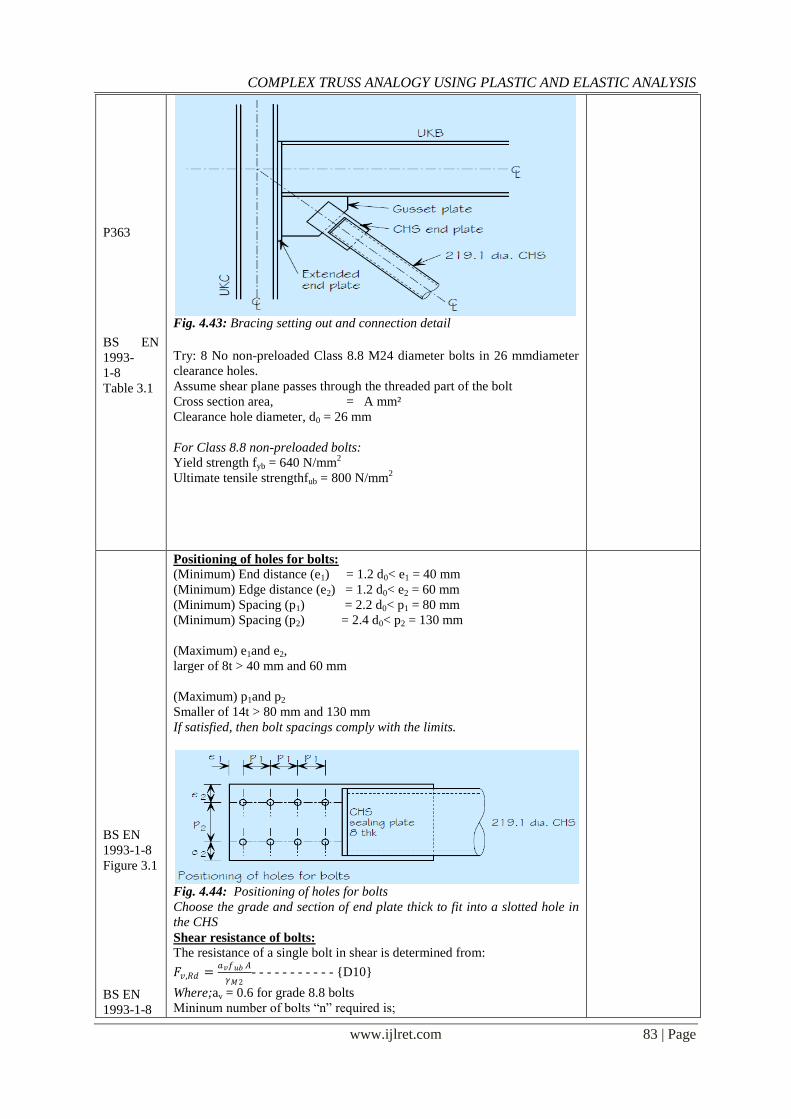
RESISTANCE OF CONNECTION Assume the CHS is connected to the frame via gusset plates. Flatend plates
fit into slots in the CHS section and are fillet welded tothe CHS. Bolts in
clearance holes transfer the load between theend plate and gusset plates.
Verify the connection resistance “N”kN tensile force.
COMPLEX TRUSS ANALOGY USING PLASTIC AND ELASTIC ANALYSIS
www.ijlret.com 83 | Page
P363
BS EN
1993-
1-8
Table 3.1
Fig. 4.43: Bracing setting out and connection detail
Try: 8 No non-preloaded Class 8.8 M24 diameter bolts in 26 mmdiameter
clearance holes.
Assume shear plane passes through the threaded part of the bolt
Cross section area, = A mm²
Clearance hole diameter, d0 = 26 mm
For Class 8.8 non-preloaded bolts:
Yield strength fyb = 640 N/mm2
Ultimate tensile strengthfub = 800 N/mm2
BS EN
1993-1-8
Figure 3.1
BS EN
1993-1-8
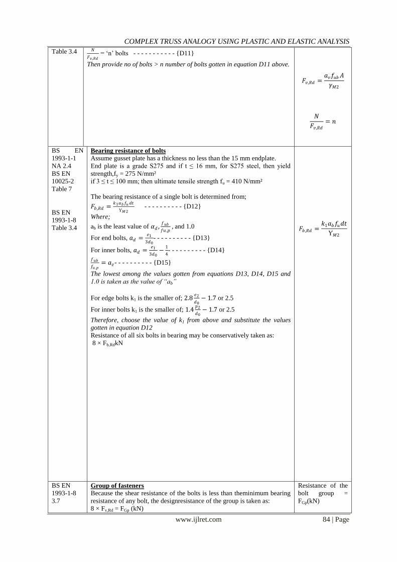
Positioning of holes for bolts:
(Minimum) End distance (e1) = 1.2 d0< e1 = 40 mm
(Minimum) Edge distance (e2) = 1.2 d0< e2 = 60 mm
(Minimum) Spacing (p1) = 2.2 d0< p1 = 80 mm
(Minimum) Spacing (p2) = 2.4 d0< p2 = 130 mm
(Maximum) e1and e2,
larger of 8t > 40 mm and 60 mm
(Maximum) p1and p2
Smaller of 14t > 80 mm and 130 mm
If satisfied, then bolt spacings comply with the limits.
Fig. 4.44: Positioning of holes for bolts
Choose the grade and section of end plate thick to fit into a slotted hole in
the CHS
Shear resistance of bolts:
The resistance of a single bolt in shear is determined from:
𝐹𝑣,𝑅𝑑 =𝑎𝑣𝑓𝑢𝑏 𝐴
𝛾𝑀2- - - - - - - - - - - {D10}
Where;av = 0.6 for grade 8.8 bolts
Mininum number of bolts “n” required is;
COMPLEX TRUSS ANALOGY USING PLASTIC AND ELASTIC ANALYSIS
www.ijlret.com 84 | Page
Table 3.4
𝑁
𝐹𝑣,𝑅𝑑 = „n‟ bolts - - - - - - - - - - - {D11}
Then provide no of bolts > n number of bolts gotten in equation D11 above.
𝐹𝑣,𝑅𝑑 =𝑎𝑣𝑓𝑢𝑏𝐴
𝛾𝑀2
𝑁
𝐹𝑣,𝑅𝑑
= 𝑛
BS EN
1993-1-1
NA 2.4
BS EN
10025-2
Table 7
BS EN
1993-1-8
Table 3.4
Bearing resistance of bolts
Assume gusset plate has a thickness no less than the 15 mm endplate.
End plate is a grade S275 and if t ≤ 16 mm, for S275 steel, then yield
strength,fy = 275 N/mm²
if 3 ≤ t ≤ 100 mm; then ultimate tensile strength fu = 410 N/mm²
The bearing resistance of a single bolt is determined from;
𝐹𝑏 ,𝑅𝑑 =𝑘1𝑎𝑏𝑓𝑢𝑑𝑡
Ƴ𝑀2 - - - - - - - - - - {D12}
Where;
ab is the least value of 𝛼𝑑 ,𝑓𝑢𝑏
𝑓𝑢 ,𝑝 , and 1.0
For end bolts, 𝑎𝑑 =𝑒1
3𝑑0- - - - - - - - - - {D13}
For inner bolts, 𝑎𝑑 =𝑒1
3𝑑0−
1
4- - - - - - - - - - {D14}
𝑓𝑢𝑏
𝑓𝑢 ,𝑝= 𝑎𝑧- - - - - - - - - - {D15}
The lowest among the values gotten from equations D13, D14, D15 and
1.0 is taken as the value of “ab”
For edge bolts k1 is the smaller of; 2.8𝑒2
𝑑0− 1.7 or 2.5
For inner bolts k1 is the smaller of; 1.4𝑝2
𝑑0− 1.7 or 2.5
Therefore, choose the value of k1 from above and substitute the values
gotten in equation D12
Resistance of all six bolts in bearing may be conservatively taken as:
8 × Fb,RdkN
𝐹𝑏 ,𝑅𝑑 =𝑘1𝑎𝑏𝑓𝑢𝑑𝑡
Ƴ𝑀2
BS EN
1993-1-8
3.7
Group of fasteners
Because the shear resistance of the bolts is less than theminimum bearing
resistance of any bolt, the designresistance of the group is taken as:
8 × Fv,Rd = FGp (kN)
Resistance of the
bolt group =
FGp(kN)
COMPLEX TRUSS ANALOGY USING PLASTIC AND ELASTIC ANALYSIS
www.ijlret.com 85 | Page
BS EN
1993-1-8
3.10.2
6.2.3(1)
6.2.3(2)
Eqn. 6.6
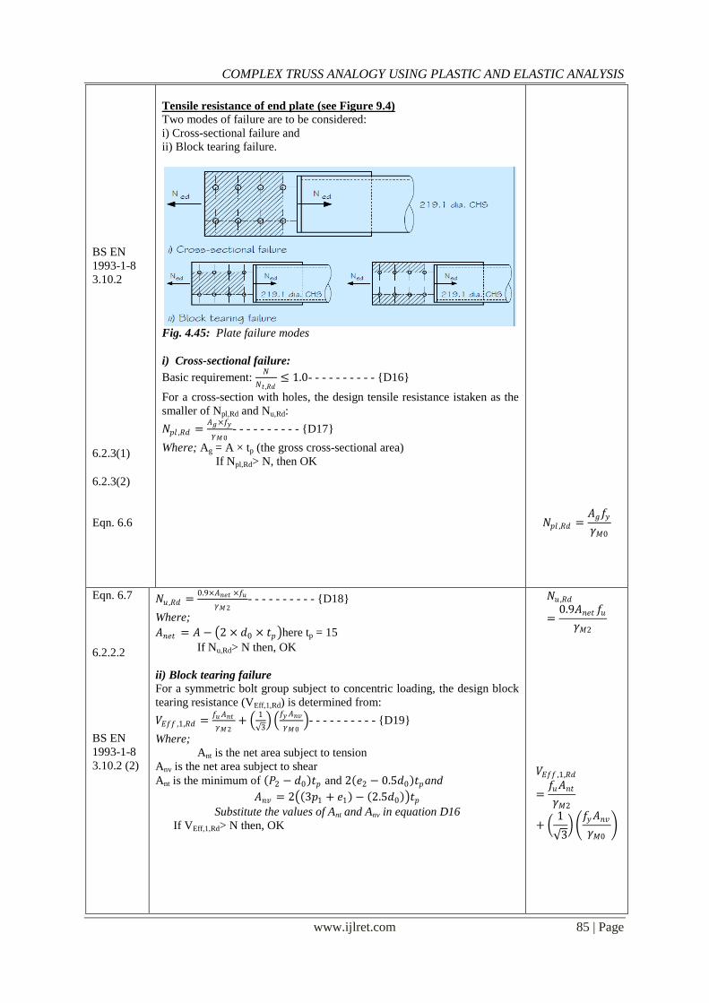
Tensile resistance of end plate (see Figure 9.4)
Two modes of failure are to be considered:
i) Cross-sectional failure and
ii) Block tearing failure.
Fig. 4.45: Plate failure modes
i) Cross-sectional failure:
Basic requirement: 𝑁
𝑁𝑡 ,𝑅𝑑≤ 1.0- - - - - - - - - - {D16}
For a cross-section with holes, the design tensile resistance istaken as the
smaller of Npl,Rd and Nu,Rd:
𝑁𝑝𝑙 ,𝑅𝑑 =𝐴𝑔×𝑓𝑦
𝛾𝑀0- - - - - - - - - - {D17}
Where; Ag = A × tp (the gross cross-sectional area)
If Npl,Rd> N, then OK
𝑁𝑝𝑙 ,𝑅𝑑 =𝐴𝑔𝑓𝑦
𝛾𝑀0
Eqn. 6.7
6.2.2.2
BS EN
1993-1-8
3.10.2 (2)
𝑁𝑢 ,𝑅𝑑 =0.9×𝐴𝑛𝑒𝑡 ×𝑓𝑢
𝛾𝑀2- - - - - - - - - - {D18}
Where;
𝐴𝑛𝑒𝑡 = 𝐴 − 2 × 𝑑0 × 𝑡𝑝 here tp = 15
If Nu,Rd> N then, OK
ii) Block tearing failure
For a symmetric bolt group subject to concentric loading, the design block
tearing resistance (VEff,1,Rd) is determined from:
𝑉𝐸𝑓𝑓 ,1,𝑅𝑑 =𝑓𝑢𝐴𝑛𝑡
𝛾𝑀2+
1
3
𝑓𝑦𝐴𝑛𝑣
𝛾𝑀0 - - - - - - - - - - {D19}
Where;
Ant is the net area subject to tension
Anv is the net area subject to shear
Ant is the minimum of 𝑃2 − 𝑑0 𝑡𝑝 and 2 𝑒2 − 0.5𝑑0 𝑡𝑝and
𝐴𝑛𝑣 = 2 3𝑝1 + 𝑒1 − 2.5𝑑0 𝑡𝑝
Substitute the values of Ant and Anv in equation D16
If VEff,1,Rd> N then, OK
𝑁𝑢 ,𝑅𝑑
=0.9𝐴𝑛𝑒𝑡 𝑓𝑢
𝛾𝑀2
𝑉𝐸𝑓𝑓 ,1,𝑅𝑑
=𝑓𝑢𝐴𝑛𝑡𝛾𝑀2
+ 1
3
𝑓𝑦𝐴𝑛𝑣
𝛾𝑀0
COMPLEX TRUSS ANALOGY USING PLASTIC AND ELASTIC ANALYSIS
www.ijlret.com 86 | Page
Discussion and Conclusion: the summary for the study on the comparison between elastic analysis and plastic analysis for the design of
complex truss.
In this lesson we have studied how the loads are transferred in bridge truss floor system. Further, we found
that there is similarity between the influence line of support reactions for simply supported beam and truss
structures. Finally we studied the influence line for truss member forces.
Influence lines as we have seen is a function whose value at any given point represents the value of some
structural quantity due to a unit force placed at that point. The influence line graphically shows how changing
the position of a single load influences various significant structural quantities. (Structural quantities:
Reactions, Shear, Moment, Deflection, etc.)
Influence lines may be used to advantage in the determination of simple beam reactions. In this case, the use
of the unit influence line is necessary. The unit influence line represents the effects of unit: reactions
(displacements), shears (separations) and moments (rotations) in a beam structure.
We have also seen how plastic method of analysis can be used to analyse not just truss systems but the
complex truss systems. Unpinning the members of the truss system makes it very much easier and very much
explanatory in the analysis of the truss systems.
Plastic analysis of the complex truss system as we have seen agrees to the theory of plasticity which says that
a structure is deemed to have reached the limits of its load bearing capacity when it forms sufficient hinges to
convert it to a mechanism with consequent collapse. This is normally one hinge more than number of degree
of indeterminacy (Ip).
The plastic collapse loads corresponding to various failure mechanisms as we have seen are obtained by
equating the internal work at the plastic hinges to the external by loads during the virtual displacement. This
requires evaluation of displacements and plastic hinge rotations.
During the last few decades, computer software has become more and more critical in the analysis of
engineering and scientific problems. Much of the reason for this change from manual methods has been the
advancement of computer techniques developed by the research community and, in particular, universities.
As both the Technology and Engineering industries advance, new methodologies of interlinking and
complementing the industries via computer applications will be created, with a similar improvement in
hardware capacities. This in turn will facilitate the implementation of more efficient and professional
engineering software. As these software applications advance in functionality, one can hope that they will be
more affordable so as to promote their widespread usage amongst civil engineers at a global scale.
The introduction of software usage in the civil engineering industry as we have seen has greatly reduced the
complexities of different aspects in the analysis and design of projects, as well as reducing the amount of time
necessary to complete the designs. Concurrently, this leads to greater savings and reductions in costs. More
complex projects that were almost impossible to work out several years ago are now easily solved with the use
of computers. In order to stay at the pinnacle of any industry, one needs to keep at par with the latest
technological advancements which accelerate work timeframes and accuracy without decreasing the reliability
and efficiency of the results.
COMPLEX TRUSS ANALOGY USING PLASTIC AND ELASTIC ANALYSIS
www.ijlret.com 87 | Page
Plastic analysis vs elastic analysis It may not be realized, but the advantages of plasticity of metal are consciously or unconsciously
made use of even in elastic design methods. For example, in the elastic method of design, if a design
is too conservative for a given permissible working stress, then the stress value is changed, indicating
that plasticity is made use of.
Advantages of the plastic method of analysis Normally, there are two distinct advantages of plastic methods over the conventional or elastic methods.
Firstly, they are more economical as they make full use of the materials strength beyond the elastic limit.
Secondly, the design procedures are much simpler and rational.
It has been observed earlier that metals, especially steel have considerable reserve of strength beyond that
elastic limit. Also, ultimate load for these can be computed more precisely and accurately. Taking advantage
of the above, the plastic methods permit use of much smaller structural section to safely support the working
loads. As regards simplicity of procedures, the plastic methods are inherently simple, as they do not take
consideration the elastic conditions of continuity, which involves tedious and complicated calculations. It is
for these reasons that plastic design methods are calculated.
In the influence line analysis, the mobile load acting on the truss system was directly applied in the
determination of the axial forces acting on the respective truss members where as for the plastic analysis
method the mobile load has to be multiplied with the section‟s load factor before analysis.
From the influence line analysis, I observed that the top chord members of the truss system are all
compression members, the lower chord members are all tension members then both the vertical strut and
braced members are being acted upon by both compression and tension forces.
The internal braced members of the truss system exist both in primary and secondary truss and has to be
designed accordingly. I also noticed that after analysis, the result showed that the braced members have the
same magnitude of compressive and tension forces.
In the influence line analysis of the complex truss designed in chapter four, the effect of the mobile load on the
truss members is highest when the position of the mobile load is at the middle of the truss system. To obtain
the maximum value of a function due to a single concentrated live load, the load should be placed at that point
where the ordinate to the influence line for that function is a maximum.
The value of a function due to the action of a single concentrated live load equals the product of the magnitude
of the load and the ordinate to the influence line for that function, measured at the point of application of load.
It is only when the reduced frame structure is pinned at the both ends and fixed at the internal support that it
will satisfy the required number of independent collapse mechanism. From the table of the combined
mechanism, It was observed that the highest Mp value required to induce collapse is 2 𝑎2𝑊2 +2𝑊4
13𝑘𝑁𝑚 and
occurs at column 13 of the table.
From the results of the reactions obtained in chapter four from the plastic method of truss analysis, the
maximum compressive axial force acting on the vertical members occurs at point J (Jy) and the maximum
tension axial force acting at the lower chord member occurs at point I (Ix)
When checking for the bending moment at all points of possible hinges, I observed that the Mps gotten are
higher than the required Mp gotten from the combined mechanism. Nevertheless, the maximum bending
moment which occurs at point E7 and C3 will be used as the design moment gotten from the plastic method of
analysis. The lower chord and the bracing members have their own respective Mps which are 8W7a2 kNm and
0.0932W6 h2 + a2 kNm respectively.
A close examination on the chapter four of this project disputes the advantages listed above in 5.3, when it
comes to the analysis of complicated truss systems acted upon by mobile loads. Unlike beams and frames truss
systems involve a combination of many members and as such it requires a lot of rigorous processes and
assumptions especially when using the plastic analysis method.
On the basis of economy, plastic method of analysis is mainly economical when it comes to the analysis of
frames and beams. When it comes to complicated truss systems acted upon by mobile load, the use of
influence line is much safer.
Plastic method of analysis does not give a clear effect of the mobile load on each member with respect to the
position of the mobile load. The use of influence line analysis gives directly the axial force exerted by the
mobile load on each truss member with respect to it‟s position.
The top chord and the strut (column) members have the same moment (i.e the maximum Mp value) when using
plastic method of analysis. With elastic method of analysis the top chord and the strut members do not have
the same design moment.
The results obtained from the research of this work shows that the influence line analysis generates higher
axial forces on members than with the plastic analysis method under the same magnitude of imposed live
COMPLEX TRUSS ANALOGY USING PLASTIC AND ELASTIC ANALYSIS
www.ijlret.com 88 | Page
loads. This is so because the plastic method of analysis involves a lot of assumptions that makes it yet not
advisable to be used in the analyses of trusses carrying mobile loads.
Influence line for mobile load analysis is easily written in a programmable form because it is easier and gives
the required axial forces directly than the plastic method of mobile analysis.
A user-friendly program for the computer analysis of influence line and plastic method of analyzing
complicated truss system and design of steel trusses has been successfully created and tested for the following:
Trussanalysis with the following variable input parameters:
Span length
Span height
Type and intensity of loading
The program instantaneously calculates and displays the following results using the above parameters:
The total axial forces acting on each member of the truss system for influence line analysis
The maximum Mp values that will be acting on the truss members for plastic method of analysis
The axial and the shear forces acting on each member when using the plastic method of analysis.
The wind loading at each beam is transferred to two vertically braced end bays on grid lines „A‟ and „J‟ by the
beams acting as diaphragms. The bracing systemcarrys the equivalent horizontal forces (EHF) in addition to
the wind loads.Locally, the bracing must carry additional loads due to imperfections at splices (cl 5.3.3(4)) and
restraint forces (cl 5.3.2(5)). These imperfections are considered in turn in conjunction with external lateral
loads but not at the same time as the EHF.The braced bays, acting as vertical pin-jointed frames, transfer the
horizontal wind load to the lower chord members.The beams and columns that make up the bracing system
have already been designed for gravity loads1). Therefore, only the diagonal members have to be designed and
only the forces in these members have to be calculated.All the diagonal members are of the same section, thus,
only the most heavily loaded member has to be designed.
Finally, there is always an assumption that trusses cannot be analysed using plastic method of analysis since
they (trusses) are subjected to axial forces and not bending. But from the research shown above in chapter
four, we have seen that trusses can be analysed using plastic moment analysis if the necessary steps are being
followed.
In this work, we have also seen how trusses can be designed using the current code for design regulation, the
Euro code 3.
Recommendation: The recommendations directly affiliated with this project are given as follows:
a) The use of influence line analysis should be used for the analysis of complicated truss systems carrying mobile
loads (e.g. bridge trusses), since it gives directly the design axial forces on each member.
b) More research or experiment should be made on plastic method of analysis of truss systems acted upon by
mobile or static loads in order to discover more benefits of using the plastic method of analysis for truss
systems.
c) Conscientious effort should be made to expose undergraduate students to the use of plastic method of analysis
in order to sensitize its use in the would be engineers.
d) To continue developing, expanding and improving this software application hoping that one day, it will be a
full structural analysis program catering for the analysis and design of frames, trusses and other structural
elements.
e) The Department of Civil Engineering at NnamdiAzikiweUniversityshould introduce a computer lab for use by
students so as to promote the use of computers in the engineering profession.
f) The department should encourage conducting similar final year projects dealing with computer applications in
the future.
g) More emphasis regarding computer technology and applications to engineering should be made at an academic
level in different courses. This would broaden the intellect of students as well as expose them to new
technologies in all engineering disciplines.
h) Civil engineering students should be thought on the use of Euro codes which is the new code for the design of
civil engineering structures as against the BS codes.
i) Modern buildings are being built using steel materials. Students/engineers should be encouraged to learn the
design of steel structures (e.g. trusses, frames, buildings e.t.c.) according to EC3 in order to suite the
contemporary world.
REFERENCES [1]. Aanicai C., (2013). Postelastic Structural Analysis. Hyperstatic structures,Gh. Asachi Technical
University of Iasi, Department of structural Mechanics, 167 pp.
[2]. Brettle M E and Brown D G, (2011). Steel Building Design: Worked examples for students. In
accordance with Eurocodesand the UK National Annexes.Published by:The Steel Construction Institute
COMPLEX TRUSS ANALOGY USING PLASTIC AND ELASTIC ANALYSIS
www.ijlret.com 89 | Page
Silwood ParkAscotBerkshire SL5 7QN, 257pp.
[3]. Brockenbrough Roger L. and Merritt Frederick (1999). STRUCTURAL STEEL DESIGNER‟S
HANDBOOK Third Edition. McGRAW-HILL, INC. Books, USA. 1201 pp.
[4]. Buick Davison and Graham W. Owens, (2003). Steel Designers manual 6th
edition. The steel
Construction Institute 1370 pp.
[5]. Chakrabarty J, (2006). Theory of Plasticity. Third edition, Published by Elsevier Butterworth-
Heinemann. 1230 pp.
[6]. Clarke R., (2012). Plastic collapse method. Structural engineering, outline of topics CE 31B. 340 pp
[7]. Code of practice for the structural use of steel, (2011). The Government of the Hong Kong Special
Administrative Region Published: October 2011, Prepared by: Buildings Department 12/F-18/F Pioneer
Centre, 750 Nathan Road, Mongkok, Kowloon, Hong Kong. 543 pp.
[8]. Das Baishali and A.V.Asha, (2010).Static and Dynamic analysis of grid beams. Department of civil
engineering National institute of technology, Rourkela. 432 pp.
[9]. Davis J.M. and Brown, (1996). Plastic Design To BS 5950. The steel construction institute, Published
by Blackwell Science. 1453 pp.
[10]. Design To BS5950-1. Introduction to BS 5950-1 and Limit State Concept. Lecture Notes, Chapter one.
Intro to BS5950. 404 pp.
[11]. Divyakamath and K.vandanareddy, (2011). Analysis and design of reinforced concrete structures-a g+5
building model.Department of civil engineering Gokarajurangaraju institute of engineering and
technology, Bachupally, Hyderabad. 690 pp.
[12]. Ezeagu, C.A. and Nwokoye, D.N. (2009). Design of Structural Timber (1st Edition), Published by Multi
Books Nigeria. 128 pp.
[13]. Ghosh Karuna Moy, (2010). Practical Design of Steel Structures based on Eurocode 3 (with case
studies):A multibay melting shop and fi nishing mill building. Whittles Publishing. 764 pp.
[14]. Hibbeler R. C., (2012). Structural Analysis, Eighth edition. Published by Pearson Prentice Hall Pearson
Education, Inc. Upper Saddle River, New Jersey 07458
[15]. Jonas Gozzi, (2004). Plastic Behaviour of structural steel: Experimental investigation and modeling.
Lulea University of Technology Department of Civil and Environmental Engineering Division of
structural Engineering – Steel structures. 832 pp.
[16]. Kalani Mohan, (2012). Basic concepts and Conventional methods of Structural analysis.Department of
civil engineering Indian institute of technology (bombay), Powai, Mumbai – 400 076, INDIA. 362 pp.
[17]. Karnovsky Igor A. andOlga Lebed, (2010). Advanced Methods of Structural Analysis. 811
NorthviewPl.Coquitlam BC V3J 3R4, Canada. 725 pp.
[18]. Kharagpur, (2012). Energy Methods in Structural Analysis. Version 2 CE IIT, Kharagpur.
[19]. Khurmi R.S., (2008). Theory of Structures. A Text book for the students of B.E., B.Tech, B.Arch., B.Sc.
Engg., Section „B‟ of AMIE (I), UPSC (Engg. Services), Diploma Courses and other Engineering
Examinations. Published by S. Chard and Company Ltd. Ram Nagar, New Delhi -110055
[20]. Kirke Brian and Al-Jamel Iyad Hassan, (2004), Fundamentals Of Structural Analysis 4th Edition
Solutions Manua. National University of Malaysia. 586 pp.
[21]. Leelataviwatet al, (2010). Plastic versus elastic design of steel structures. Structral engineering and
geomechanics– SutatLeelataviwat, Subhash C. Goel , Shih-Ho Chao. 749 pp.
[22]. Liuet al, (2009), Finite Element Analysis of Reinforced Concrete StructuresUnder Monotonic Loads, A
Report on Research Conducted underGrant RTA-59M848 from theCalifornia Department of
Transportation. 124 pp.
[23]. MacGinley T.J., (2005). Steel Structures: Practical design studies, Second edition. Nanyang
Technological UniversitySingapore.Published by E & FN Spon, an imprint of Thomson Professional,
2–6Boundary Row, London SE1 8HN, UK. 198 pp.
[24]. Martin L.H. andPurkiss J.A. (2008). Structural Design of Steelwork to EN 1993 and EN 1994, Third
edition. Linacre House, Jordan Hill, Oxford OX2 8DP, UK, Typeset by Charon Tec Ltd (A Macmillan
Company), Chennai, India. 487 pp
[25]. Mau S. T.,(2002). Fundamentals of Structural Analysis. Registration number TXu1-086-529, February
17, 2003. United States Copyright Office, The Library of Congress. 331 pp
[26]. McKenzieW.M.C., (2006). Examples in Structural Analysis. Published in the Taylor & Francis e-
Library, 2006. 1380 pp.
[27]. Mosley Bill et al, (2007). Reinforced concrete design to Eurocode 2, Sixth edition, Published by
Palgrave Macmillan 2007, Houndmills, Basingstoke, Hampshire RG21 6XS and 175 fifth avenue, New
York, N.Y. 10010.
[28]. Nataraja M. C. (2011). Design of Steel Structures, Portion covered: Two chapters in PART A 06CV72.
367 pp.
[29]. Neal B.G, (1977).The Plastic Methods of Structural Analysis. LONDONCHAPMAN AND HALL. A
COMPLEX TRUSS ANALOGY USING PLASTIC AND ELASTIC ANALYSIS
www.ijlret.com 90 | Page
Halsted PressnBook John Wiley&. Sons. New York. 564 pp.
[30]. Okoro C. J, (2004). The Plastic behavior of Structures. Project work, Department of Civil Engineering,
Enugu State University of Science and Technology. 102 pp.
[31]. Reynolds Charles E. and Steedman James C. (2005), Reinforced Concrete Designers Handbook. Tenth
Edition.Purblished by Spon Press – Taylor and Francis group, London.
[32]. RosenDavid, (2009), Panel zone Behaviour in Steel moment Resisting Frames. Earthquake engineering
andEngineering seismology National University of Malaysia.
[33]. RostomFady A.S., (2007).Computer Analysis & Reinforced Concrete Design Of Beams. 2nd
Edition,
McGraw Hill. 465 pp.
[34]. Saouma Victor E. (2007). STRUCTURAL ENGINEERING: Analysis and Design. Dept. of Civil
Environmental and Architectural Engineering, University of Colorado, Boulder, CO 80309-0428. 142
pp
[35]. Satish Kumar and Santha Kumar, (2009). Design of Steel structures. Indian Institute of Technology
Madras, AscotBerkshire SL5 7QN. 687 pp.
[36]. Shanmugam N. E. and Narayanan R., (2008). Structural analysis, ICE Manual of Bridge Engineering #
2008 Institution of Civil Engineers, National University of Malaysia, Duke University and Manhattan
College. 187 pp.
[37]. Structures Design Manual for Highways and Railways, (2006). Third Edition, Highways Department,
Government of the Hong Kong Special Administrative Region. 265 pp.
[38]. UstundagCenk, (2005), Analysis of Statically Determinate Trusses. Theory of Strustures. 198 pp.
[39]. W. Zhang and L. F. (Yang, 2012), Study On Influence Factor Of Plastic Limit Analysis BasedOn
Elastic Compensation Finite Element Method. The 10th International Symposium on Structural
Engineering for Young Experts, School of Civil Engineering and Architecture, Guangxi University,
Nanning, 530004, P.R. China.561 pp
[40]. Wang Hongqing and Rosen David, (2009). Computer-Aided Design Methods for Additive Fabrication
of Truss Structures. The George W. Woodruff School of Mechanical EngineeringGeorgia Institute of
Technology Atlanta, GA 30332-0405 USA404- 894-2
[41]. Wong M. Bill,(2009). Plastic Analysis and Design of Steel Structures, Department of Civil Engineering
Monash University, Australia. TA684.W66 2009, 624.1‟821--dc22
[42]. www.bookspar.com, (2012). Plastic Behaviour of Structural Steel. Unit – 4. VTU, Lulea University of
Technology Department of Civil and Environmental Engineering. 144 pp.


![Lecture Two: The Analogy Theory [‘AT’] · Lecture Two: The Analogy Theory ... 2. [AT] claims: OM-judgments justified by an argument from analogy ... iPaul Bartha, “Analogy and](https://img.pdfslide.us/doc/110x75/5b1ae5387f8b9a28258e143b/lecture-two-the-analogy-theory-at-lecture-two-the-analogy-theory-.jpg)