Embed Size (px)
Citation preview
Lee et al. Vol. 17, No. 3 /March 2000/J. Opt. Soc. Am. B 401
Complex traversal time for optical pulsetransmission in a Fabry–Perot cavity
Jae Yong Lee and Hai-Woong Lee
Department of Physics, Korea Advanced Institute of Science and Technology, 373-1 Kusong-dong Yusong-gu,Taejon 305-701, Korea
Jae Won Hahn
Optical High Temperature Measurement Group, Korea Research Institute of Standards and Science,P.O. Box 102, Yusong, Taejon 305-600, Korea
Received July 1, 1999; revised manuscript received October 26, 1999
We show that the physical clock approach can be applied to the problem of optical pulse transmission in theFabry–Perot cavity. Our theoretical analysis leads directly to a complex-valued traversal time for the pulse.Real and imaginary parts of the traversal time, referred to as the phase time and the loss time, are associated,respectively, with the rotation angle of polarization and the change in the polarization ellipticity of the outgo-ing pulse in the presence of a magnetic clock. The physical significance of the phase time and the loss time isdiscussed in relation to the superluminal group velocity and the spectral shift of the pulse. © 2000 OpticalSociety of America [S0740-3224(00)00903-6]
OCIS codes: 120.2230, 120.3180, 120.7000.
1. INTRODUCTIONHow much time it takes for a particle to traverse a poten-tial barrier in a given region of space is a fundamentalquestion that has often been addressed.1–12 The issuehas been brought an increased practical importance aswell by the recent advances in high-speed semiconductortechnology based on tunneling devices and ultrafastoptoelectronics.13 Theoretical and experimental studiesso far have dealt not only with the quantum particle tun-neling problem but also with various problems in the elec-tromagnetic wave regime, including evanescent wavepropagation in a waveguide,14,15 optical tunneling in frus-trated total internal reflection,8 and optical pulse trans-mission through a photonic bandgap.16–19 The analogybetween quantum tunneling and classical wave propaga-tion stems from the formal equivalence between theSchrodinger equation and the Helmholtz equation.20,21
Investigation of the traversal time problem with electro-magnetic waves has provided an opportunity for easier in-terpretations and experimental conditions, allowing morefeasible temporal and spatial measurements than thosewith quantum particles, namely, electrons.8,16 Exploringthe traversal time, however, is not a simple matter, andefforts to define a physically meaningful traversal timehave witnessed a diversity of viewpoints and a lack ofclear consensus.2
In this paper we investigate the problem of the tra-versal time for optical pulse transmission in a Fabry–Perot cavity. The principal tool for our investigation isthe physical clock,4–8 an idea that originated with Baz’4
and was recently formulated by Gasparian et al.6 for theproblem of optical wave traversal through a slab material.We show that the physical clock approach applied to op-tical pulse propagation in a Fabry–Perot cavity leads di-
0740-3224/2000/030401-06$15.00 ©
rectly to a complex-valued traversal time. As in the pre-vious work of Gasparian et al.,6 the real and theimaginary parts of the complex traversal time are con-nected directly with experimentally measurable quanti-ties. The significance of our work lies in the fact that theFabry–Perot cavity, as one of the simplest optical configu-rations, serves to facilitate both theoretical and experi-mental investigations of the traversal time; the boundarycondition can be given arbitrarily by the cavity mirrorcharacteristics (i.e., reflectivity R 5 uRu2 and transmittiv-ity T 5 uT u2), and the dimension of the system (i.e., thecavity length L) is unrestricted in principle. Investiga-tion of the complex-valued traversal time for the Fabry–Perot cavity will extend our knowledge of this simplestbut versatile optical system itself as well as help us un-derstand the physics of tunneling phenomena.
2. MAGNETIC CLOCK FOR A LIGHT PULSEPROPAGATING IN A FABRY–PEROTCAVITYWe consider a light wave incident upon a Fabry–Perotcavity consisting of two identical mirrors with reflectivityR 5 uRu2 and transmittivity T 5 uT u2 separated by a me-dium of length L with refractive index n0 . The ampli-tude transmission function of the cavity that determinesthe frequency characteristics of the transmitted wave isgiven by22
K~v! 5 A~v!exp@if~v!#
5 (m50
`
T 2 R2m expF ivtrS m 112 D G
5T 2 exp~ivtr/2!
1 2 R2 exp~ivtr!, (1)
2000 Optical Society of America
402 J. Opt. Soc. Am. B/Vol. 17, No. 3 /March 2000 Lee et al.
where tr 5 2n0L/c is the cavity round-trip time and thesummation over m signifies contributions from all differ-ent paths having different numbers of round trips insidethe cavity. The intensity transmission function is ob-tained from the absolute square of K(v) and is given by
uK~v!u2 5~1 2 R !2
~1 2 R !2 1 4R sin2~12 vtr 1 wr!
, (2)
where R 5 uRuexp(iwr) 5 AR exp(iwr); the cavity is as-sumed hereafter to have no loss, so that R 1 T 5 1. Ifthe frequency of the incident wave does not lie close to thecavity resonance frequency vc 5 2(Np 2 wr)/tr and R issufficiently close to 1, the intensity transmission functionis uK(v)u2 ; (1 2 R)2/4 ! 1. For the rest of this paperwe assume that the carrier frequency vp of the incidentpulse is located sufficiently far from any of the resonancefrequencies and that the frequency bandwidth Dvp of thepulse is narrow compared with the cavity resonance modespacing 2p/tr . During transmission the incident pulsethen experiences a significant intensity attenuation, butits temporal shape changes little owing to the nearly flatspectral transmittance of the cavity.
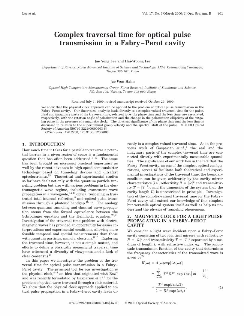
An attempt to define a traversal time for such a pulsedirectly, however, encounters difficulty because the finaltransmission of the pulse is a result of contributions fromdifferent paths involving different numbers of reflectionsthat are associated with different traversal times. Insuch a situation it is perhaps more appropriate to definethe traversal time in terms of a change in a physicalquantity possessing a linear relation with the time of in-teraction experienced by the transmitted pulse. In accor-dance with the magnetic clock approach,6 we assume thata constant magnetic field B is applied to the medium in-side the cavity along the direction of the cavity axis,which we take as the z axis. The incident pulse propa-gates along the z axis and is linearly polarized along the xaxis (see Fig. 1). The presence of the magnetic field pro-duces two effects on the pulse as schematically shown inFig. 1. First, the magnetic field rotates the axis of polar-ization in the xy plane. This is the Faraday effect causedby the fact that different phase velocities are associatedwith left and right circularly polarized light. Second, themagnetic field generates ellipticity. That is, when thepulse leaves the medium, it is no longer linearly polar-ized; it is in general elliptically polarized. This is causedby the differential transmission of the cavity induced bythe medium birefringence. These two effects can be con-veniently described by a complex angle defined as
Fig. 1. Principle of the magnetic clock defining the traversaltime in a Fabry–Perot cavity. The complex traversal time withmultiple reflections taken into account is introduced by theresultant complex angle in the presence of mirrors forming acavity.
tan u 5Ey
Ex
5 2iE1 2 E2
E1 1 E2
5 2iK1 2 K2
K1 1 K2
, (3)
where Ex and Ey , respectively, are the x and the y com-ponents of the electric field of the outgoing pulse, E1
5 (Ex 1 iEy)/A2 and E2 5 (Ex 2 iEy)/A2 represent theright and the left circularly polarized components of theelectric field of the outgoing pulse, and K1
5 A1 exp(if1) and K2 5 A2 exp(if2) refer, respec-tively, to the amplitude transmission function for theright and the left circularly polarized light. The lastequality in Eq. (3) follows from the fact that the incidentpulse linearly polarized in the x direction is a superposi-tion of right and left circularly polarized fields of the samecomplex amplitude. From Eq. (3) we immediately obtain,for the Faraday angle u,
u [ u1 2 iu2 5~ f1 2 f2!
22 i
ln~A1 /A2!
2. (4)
The real component u1 represents the rotation angle ofpolarization, and the imaginary component u2 determinesthe degree of ellipticity of the outgoing pulse. With thisFaraday angle u presumed to be proportional to the time tof the pulse interacting with the medium as well as to themagnetic field applied, the traversal time is readily ob-tained.
3. COMPLEX TRAVERSAL TIME FORA LIGHT PULSE PROPAGATING INA FABRY–PEROT CAVITYThe complex Faraday angle u allows one to define a com-plex traversal time t 5 u/VB for a light wave transmit-ting through a Fabry–Perot cavity, where VB is the Far-aday rotation frequency given by VB 5 vDnB/2n0 , n0 isthe index of refraction of the medium in the absence of themagnetic field, and DnB is the difference in indices of re-fraction for right (n1) and left (n2) circularly polarizedlight (n6 5 n0 6 DnB/2). Assuming a sufficiently weakmagnetic field, we have
f1 2 f2 5 f~n1! 2 f~n2!
. @]f~n0!/]n0#DnB ,
ln~A1 /A2! 5 ln@A~n1!/A~n2!#
. @] ln A~n0!/]n0#DnB ,
and thus
t [ t1 2 it2 .n0
vF ]f~n0!
]n0
2 i] ln A~n0!
]n0G . (5)
We note that the traversal time t is independent of themagnetic field applied for probing the traversal time andis determined only by the transmission characteristics ofthe Fabry–Perot cavity.
Substituting Eq. (1) into relation (5) and using theidentity ]K/]v 5 (n0 /v)(]K/]n0), we obtain the desiredexpressions for t1 and t2 for a light wave transmittingthrough the Fabry–Perot cavity:
Lee et al. Vol. 17, No. 3 /March 2000/J. Opt. Soc. Am. B 403
t1 5]f~v!
]v
51 2 R2
~1 2 R !2 1 4R sin2~12 vtr 1 wr!
tr
2, (6)
t2 5] ln A~v!
]v
522R sin~vtr 1 2wr!
~1 2 R !2 1 4R sin2~12 vtr 1 wr!
tr
2. (7)
We refer to t1 and t2 as the phase time23 and the losstime,8 respectively.
Some insight into the complex traversal time t can beobtained by our considering the average time spent by thepulse inside the cavity. The average time can be com-puted by taking the average of times required for thepulse to complete each different path with an appropriateweight, in the spirit of Sokolovski and Baskin.10 Fromthe expression for the frequency response function K(v)given by Eq. (1), a reasonable weight for the path associ-ated with m round trips inside the cavity is taken to bethe complex amplitude T 2R2m exp@ivtr(m 1
12 )#. The
average time tav can then be expressed as
tav 5
(m50
`
~m 112 !trT 2R2m exp@ivtr~m 1
12 !#
(m50
`
T 2R2m exp@ivtr~m 112 !#
. (8)
It is clear from Eq. (8), with the aid of Eq. (1), that
tav 51
iK~v!
]K~v!
]v
5 2i] ln K~v!
]v5
]f~v!
]v2i
] ln A~v!
]v5 t. (9)
Thus the average time defined as above is simply the com-plex traversal time t. This correspondence implies thatthe complex nature exhibited by the traversal time is aconsequence of the phase-dependent wave character ofthe interference phenomena involved in both the math-ematical definition and the physical clock. The general-ity in the average time requires the complex traversaltime to be invariant over the choice of a physical clock ifthe clocks are based on a similar type of phase-sensitivemeasurement with two degrees of freedom.
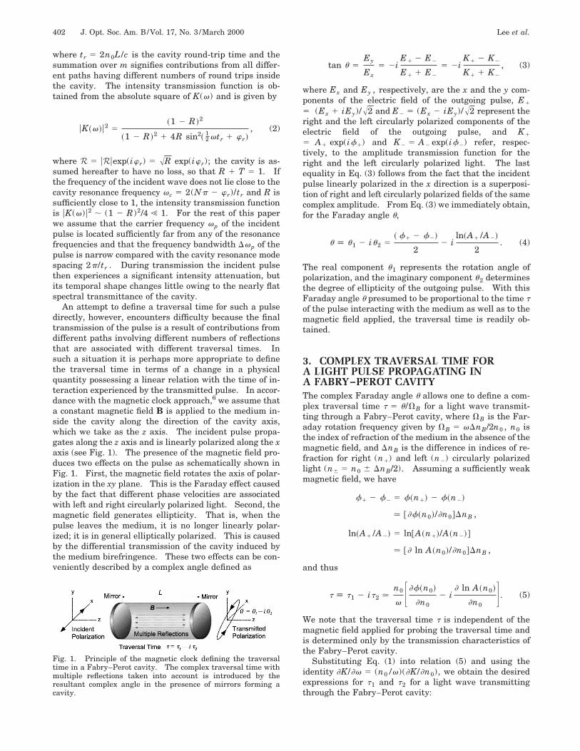
The general behavior of the phase time and the losstime is shown in Figs. 2(a) and 2(b), in which the phasetime and the loss time computed from Eqs. (6) and (7), re-spectively, are plotted as a function of frequency for threedifferent values of the mirror reflectivity. We see fromFig. 2(a) that the phase time remains small if the fre-quency of the incident pulse is sufficiently far from thecavity resonance frequencies. In particular, for a pulsefrequency satisfying the antiresonance condition vtr1 2wr 5 (2N 1 1)p, we obtain
t1 51 2 R1 1 R
tr
2, (10)
which is typically much shorter than the single-pass timetr/2, if R is close to 1. This means that an antiresonantlytransmitted optical pulse traversing a Fabry–Perot cavityexperiences much less polarization rotation than thesame pulse propagating in the same medium without mir-rors. We see also from Fig. 2(a) that the phase time isalways positive and exhibits little dispersion in the fre-quency region sufficiently far from the cavity resonancefrequencies, especially if the reflectivity R is high. Fig-ure 2(b) indicates that, in contrast to the phase time, theloss time can take on negative as well as positive valueswith its absolute value limited by ut2u & tr/2 and exhibitsa stronger degree of dispersion. Furthermore, the losstime does not greatly depend on the mirror reflectivity inthe region near antiresonance frequencies. Althoughwhich component of the complex traversal time best char-acterizes the process being considered is still an issue ofdebate,1,2,10 the facts that the loss time can be negativeand zero and that it exhibits a stronger degree of spectraldispersion seem to indicate that the phase time may bethe better candidate, at least for our case of an opticalpulse traversing a Fabry–Perot cavity. In the followingsections we discuss in detail the physical significance ofthe phase time and the loss time.
Fig. 2. Complex traversal time of a Fabry–Perot cavity. (a)The real component (phase time) and (b) the imaginary compo-nent (loss time) are plotted as a function of the optical frequencydetuning from the nearest lower resonance frequency 2pN/tr forthree different values of the cavity mirror reflectivity R, 0.50,0.90, and 0.99.
404 J. Opt. Soc. Am. B/Vol. 17, No. 3 /March 2000 Lee et al.
4. PHASE TIME AND SUPERLUMINALGROUP VELOCITYIn this section we look further into the details of thephase time. The phase time t1 is associated with theFaraday rotation angle u1 experienced by the pulse trans-mitted through the Fabry–Perot cavity and can thereforebe measured experimentally. The phase time is a pos-sible measure of the interaction time between the pulseand the medium in the cavity, because the Faraday rota-tion angle in the normal case of an optical pulse propagat-ing in a medium without mirrors is proportional to the in-teraction time spent in the medium as well as to themagnetic field applied.
The phase time for our case of an optical pulse trans-mitted through the Fabry–Perot cavity is identical withthe arrival time18,19,23,24 of the pulse at the exit of the tra-versed region. To see this, we recall that the effectivegroup velocity vg of a wave packet is given by vg5 @d Re k(v)/dv#21 and, for our case of the Fabry–Perotcavity of length L whose frequency response function isgiven by Eq. (1), we have vg 5 L@df(v)/dv#21.25 Thearrival time ta 5 L/vg is then equal to the phase time t1 .Since the phase time is typically much shorter than thenormal single-pass time tr/2 as shown in the previous sec-tion, the group velocity vg 5 L/ta 5 L/t1 can clearly ex-hibit superluminality.18,19,25–32 In particular, if the pulsefrequency satisfies the antiresonance condition vtr1 2wr 5 (2N 1 1)p, the group velocity is as large asvg 5 (c/n0)@(1 1 R)/(1 2 R)#. The group velocity, evenif it can be superluminal, has been shown both theoreti-cally and experimentally to be the best measure to deter-mine the arrival time of the peak of a wave packet.18,19
To confirm the superluminal group velocity of an opticalpulse traversing the Fabry–Perot cavity, we performed anumerical calculation of optical pulse transmission in thetime domain. With a normalized minimum-uncertaintyGaussian pulse input E in(t) 5 (4 ln 2/ptp
2)1/4
3 exp@22 ln 2(t/tp)2#exp(2ivpt), the temporal responseof the Fabry–Perot cavity at the exit mirror, Eout(t),hasbeen obtained by the convolution Eout 5 *G(t2 t8)E in(t8)dt8, where the Green’s function G(t) is givenby
G~t ! 5 (m50
`
T 2R2md ~t 2 @m 1 1/2#tr!, (11)
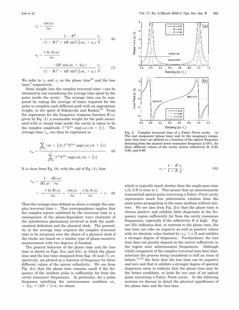
where d (t) is the Kronecker delta function. The result ofthe calculation is displayed in Fig. 3(a), which shows thetransmitted pulse for the case n0 5 1 (vacuum), R5 0.99, tp 5 3tr , under the antiresonance condition.The peak of the transmitted pulse escapes the cavity att 5 5.4 3 1023tr/2, implying a superluminal group veloc-ity of vg . 185c. This numerical result is in reasonableagreement with the theoretically predicted phase time,calculated from Eq. (6), of t 5 5 3 1023tr/2 and the cor-responding group velocity of vg 5 199c under the condi-tion of exact antiresonance. We note that the discrep-ancy between the numerical and the theoretical values isnot caused by numerical errors but by the dispersion ofthe phase time shown in Fig. 3(b), arising from the finite
bandwidth of the incident pulse. Incident pulses withlonger time durations have been confirmed to producesmaller discrepancies.
The superluminality exhibited here can be explained asan ‘‘optical pulse reshaping process.’’26 A Fabry–Perotcavity is an optical system that preferentially attenuatesthe later parts of an incident pulse in such a way that theoutput peak appears shifted toward earlier times. Whilethe later parts of the pulse disappear almost completelyunder the antiresonance condition because of destructiveinterference between waves corresponding to differentpaths with different numbers of round trips inside thecavity, the leading part of the pulse experiences incom-plete destructive interference because of the absence of apreceding wave packet to interfere destructively with.The causality is fortified in part by the facts, implying asubluminal energy velocity,29,32 that the transmittedpulse is considerably attenuated during transmission andthat its intensity is no greater at each moment than thatof the delayed incident pulse that would have been propa-gated without the cavity mirrors; thus the transmissionpeak can occur only within the leading front of the de-layed incident pulse, as is clearly illustrated in Fig. 3(a).The fact that the superluminality arises from the calcula-tion with the Green’s function of Eq. (11), which offers aclear causal interpretation, indicates that no violation ofEinstein’s causality takes place here. Perhaps the clear-est demonstration of causality is accomplished by consid-
Fig. 3. Superluminal optical pulse transmission through aFabry–Perot cavity with R 5 0.99 for an incident Gaussianpulse of FWHM tp 5 6tr/2. (a) Temporal evolution of the trans-mitted pulse exhibiting the arrival time of only 5.4 3 1023 of thesingle-pass time tr/2 and the narrowed pulse width of 5.75tr/2.(b) Dispersion of the phase time and the loss time over the inci-dent pulse spectrum, producing slight discrepancies in the ar-rival time and the resultant pulse width.
Lee et al. Vol. 17, No. 3 /March 2000/J. Opt. Soc. Am. B 405
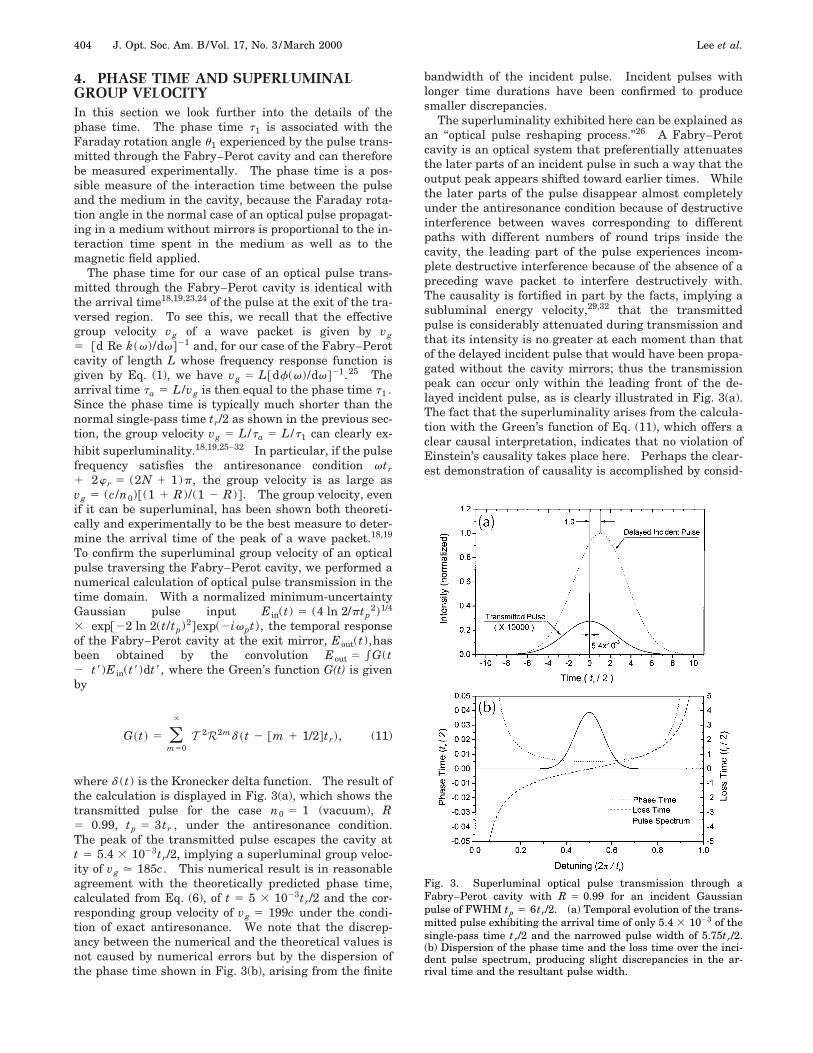
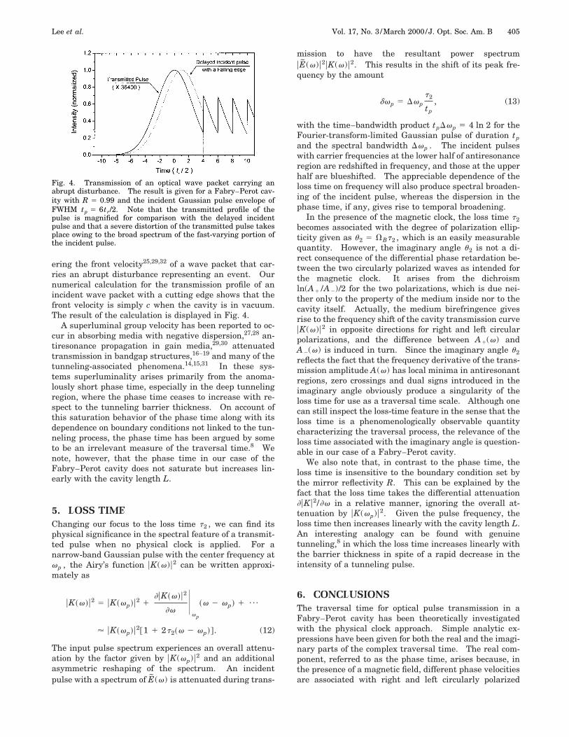
ering the front velocity25,29,32 of a wave packet that car-ries an abrupt disturbance representing an event. Ournumerical calculation for the transmission profile of anincident wave packet with a cutting edge shows that thefront velocity is simply c when the cavity is in vacuum.The result of the calculation is displayed in Fig. 4.
A superluminal group velocity has been reported to oc-cur in absorbing media with negative dispersion,27,28 an-tiresonance propagation in gain media,29,30 attenuatedtransmission in bandgap structures,16–19 and many of thetunneling-associated phenomena.14,15,31 In these sys-tems superluminality arises primarily from the anoma-lously short phase time, especially in the deep tunnelingregion, where the phase time ceases to increase with re-spect to the tunneling barrier thickness. On account ofthis saturation behavior of the phase time along with itsdependence on boundary conditions not linked to the tun-neling process, the phase time has been argued by someto be an irrelevant measure of the traversal time.8 Wenote, however, that the phase time in our case of theFabry–Perot cavity does not saturate but increases lin-early with the cavity length L.
5. LOSS TIMEChanging our focus to the loss time t2 , we can find itsphysical significance in the spectral feature of a transmit-ted pulse when no physical clock is applied. For anarrow-band Gaussian pulse with the center frequency atvp , the Airy’s function uK(v)u2 can be written approxi-mately as
uK~v!u2 5 uK~vp!u2 1]uK~v!u2
]vU
vp
~v 2 vp! 1 ¯
' uK~vp!u2@1 1 2t2~v 2 vp!#. (12)
The input pulse spectrum experiences an overall attenu-ation by the factor given by uK(vp)u2 and an additionalasymmetric reshaping of the spectrum. An incidentpulse with a spectrum of E(v) is attenuated during trans-
Fig. 4. Transmission of an optical wave packet carrying anabrupt disturbance. The result is given for a Fabry–Perot cav-ity with R 5 0.99 and the incident Gaussian pulse envelope ofFWHM tp 5 6tr/2. Note that the transmitted profile of thepulse is magnified for comparison with the delayed incidentpulse and that a severe distortion of the transmitted pulse takesplace owing to the broad spectrum of the fast-varying portion ofthe incident pulse.
mission to have the resultant power spectrumuE(v)u2uK(v)u2. This results in the shift of its peak fre-quency by the amount
dvp 5 Dvpt2
tp
, (13)
with the time–bandwidth product tpDvp 5 4 ln 2 for theFourier-transform-limited Gaussian pulse of duration tpand the spectral bandwidth Dvp . The incident pulseswith carrier frequencies at the lower half of antiresonanceregion are redshifted in frequency, and those at the upperhalf are blueshifted. The appreciable dependence of theloss time on frequency will also produce spectral broaden-ing of the incident pulse, whereas the dispersion in thephase time, if any, gives rise to temporal broadening.
In the presence of the magnetic clock, the loss time t2becomes associated with the degree of polarization ellip-ticity given as u2 5 VBt2 , which is an easily measurablequantity. However, the imaginary angle u2 is not a di-rect consequence of the differential phase retardation be-tween the two circularly polarized waves as intended forthe magnetic clock. It arises from the dichroismln(A1 /A2)/2 for the two polarizations, which is due nei-ther only to the property of the medium inside nor to thecavity itself. Actually, the medium birefringence givesrise to the frequency shift of the cavity transmission curveuK(v)u2 in opposite directions for right and left circularpolarizations, and the difference between A1(v) andA2(v) is induced in turn. Since the imaginary angle u2reflects the fact that the frequency derivative of the trans-mission amplitude A(v) has local minima in antiresonantregions, zero crossings and dual signs introduced in theimaginary angle obviously produce a singularity of theloss time for use as a traversal time scale. Although onecan still inspect the loss-time feature in the sense that theloss time is a phenomenologically observable quantitycharacterizing the traversal process, the relevance of theloss time associated with the imaginary angle is question-able in our case of a Fabry–Perot cavity.
We also note that, in contrast to the phase time, theloss time is insensitive to the boundary condition set bythe mirror reflectivity R. This can be explained by thefact that the loss time takes the differential attenuation]uKu2/]v in a relative manner, ignoring the overall at-tenuation by uK(vp)u2. Given the pulse frequency, theloss time then increases linearly with the cavity length L.An interesting analogy can be found with genuinetunneling,8 in which the loss time increases linearly withthe barrier thickness in spite of a rapid decrease in theintensity of a tunneling pulse.
6. CONCLUSIONSThe traversal time for optical pulse transmission in aFabry–Perot cavity has been theoretically investigatedwith the physical clock approach. Simple analytic ex-pressions have been given for both the real and the imagi-nary parts of the complex traversal time. The real com-ponent, referred to as the phase time, arises because, inthe presence of a magnetic field, different phase velocitiesare associated with right and left circularly polarized
406 J. Opt. Soc. Am. B/Vol. 17, No. 3 /March 2000 Lee et al.
light. The phase time measures the rotation angle of po-larization. The imaginary component, referred to as theloss time, arises because, in the presence of a magneticfield, different transmission intensities are associatedwith right and left circularly polarized light. The losstime measures the degree of ellipticity of the outgoingpulse. The relevance of the loss time as a measure of thetraversal time in our case, however, is not well estab-lished, because the loss time exhibits an appreciable spec-tral dispersion and, more seriously, can take on negativevalues. The phase time, on the other hand, is alwayspositive and yields for our case the arrival time of thepeak of the pulse. Both the phase time and the loss timeare, however, easily measurable and may be considered togive time scales characterizing the transmission processof an optical pulse through a Fabry–Perot cavity.
ACKNOWLEDGMENTSThis work was supported in part by the Korea Ministry ofScience and Technology and by a Korea Advanced Insti-tute of Science and Technology Research Grant. H.-W.Lee’s e-mail address is [email protected].
REFERENCES1. E. H. Hauge and J. A. Sto”vneng, ‘‘Tunneling times: a criti-
cal review,’’ Rev. Mod. Phys. 61, 917–936 (1989).2. R. Landauer and Th. Martin, ‘‘Barrier interaction time in
tunneling,’’ Rev. Mod. Phys. 66, 217–228 (1994).3. M. Buttiker and R. Landauer, ‘‘Traversal time for tunnel-
ing,’’ Phys. Rev. Lett. 49, 1739–1742 (1982).4. A. I. Baz’, ‘‘Life-time of intermediate states,’’ Yad. Fiz. 4,
252–260 (1966).5. M. Buttiker, ‘‘Larmor precession and the traversal time for
tunneling,’’ Phys. Rev. B 27, 6178–6188 (1983).6. V. Gasparian, M. Ortuno, J. Ruiz, and E. Cuevas, ‘‘Faraday
rotation and complex-valued traversal time for classicallight waves,’’ Phys. Rev. Lett. 75, 2312–2315 (1995).
7. M. Deutsch and J. E. Golub, ‘‘Optical Larmor clock: mea-surement of the photonic tunneling time,’’ Phys. Rev. A 53,434–439 (1996).
8. Ph. Balcou and L. Dutriaux, ‘‘Dual optical tunneling timesin frustrated total internal reflection,’’ Phys. Rev. Lett. 78,851–854 (1997).
9. E. Pollak and W. H. Miller, ‘‘New physical interpretationfor time in scattering theory,’’ Phys. Rev. Lett. 53, 115–118(1984).
10. D. Sokolovski and L. M. Baskin, ‘‘Traversal time in quan-tum scattering,’’ Phys. Rev. A 36, 4604–4611 (1987).
11. K. L. Jensen and F. A. Buot, ‘‘Numerical calculation of par-ticle trajectories and tunneling times for resonant tunnel-ing barrier structures,’’ Appl. Phys. Lett. 55, 669–671(1989).
12. J. G. Muga, S. Brouard, and R. Sala, ‘‘Transmission and re-flection tunneling times,’’ Phys. Lett. A 167, 24–28 (1992).
13. K. L. Jensen and F. A. Buot, ‘‘The methodology of simulat-ing particle trajectories through tunneling structures usinga Wigner distribution approach,’’ IEEE Trans. Electron De-vices 38, 2337–2347 (1991).
14. A. Enders and G. Nimtz, ‘‘Photonic-tunneling experiments,’’Phys. Rev. B 47, 9605–9609 (1993).
15. R. Pelster, V. Gasparian, and G. Nimtz, ‘‘Propagation ofplane waves and of waveguide modes in quasiperiodic di-electric heterostructures,’’ Phys. Rev. E 55, 7645–7655(1997).
16. Ch. Spielmann, R. Szipocs, A. Stingl, and F. Krausz, ‘‘Tun-neling of optical pulses through photonic band gaps,’’ Phys.Rev. Lett. 73, 2308–2311 (1994).
17. A. M. Steinberg and R. Y. Chiao, ‘‘Subfemtosecond determi-nation of transmission delay times for a dielectric mirror(photonic band gap) as a function of the angle of incidence,’’Phys. Rev. A 51, 3525–3528 (1995).
18. W. M. Robertson, ‘‘Transmission-line matrix modeling ofsuperluminal electromagnetic-pulse tunneling through theforbidden gap in two-dimensional photonic band struc-tures,’’ J. Opt. Soc. Am. B 14, 1066–1073 (1997).
19. V. Laude and P. Tournois, ‘‘Superluminal asymptotic tun-neling times through one-dimensional photonic bandgapsin quarter-wave-stack dielectric mirrors,’’ J. Opt. Soc. Am.B 16, 194–198 (1999).
20. Th. Martin and R. Landauer, ‘‘Time delay of evanescentelectromagnetic waves and the analogy to particle tunnel-ing,’’ Phys. Rev. A 45, 2611–2617 (1992).
21. A. M. Steinberg and R. Y. Chiao, ‘‘Tunneling delay times inone and two dimensions,’’ Phys. Rev. A 49, 3283–3295(1994).
22. M. Born and E. Wolf, Principles of Optics, 6th ed. (Perga-mon, Oxford, 1986).
23. E. P. Wigner, ‘‘Lower limit for the energy derivative of thescattering phase shift,’’ Phys. Rev. 98, 145–147 (1955).
24. T. E. Hartman, ‘‘Tunneling of a wave packet,’’ J. Appl.Phys. 33, 3427–3433 (1962).
25. G. Diener, ‘‘Superluminal group velocities and informationtransfer,’’ Phys. Lett. A 223, 327–331 (1996).
26. A. M. Steinberg, P. G. Kwiat, and R. Y. Chiao, ‘‘Measure-ment of the single-photon tunneling time,’’ Phys. Rev. Lett.71, 708–711 (1993).
27. C. G. B. Garrett and D. E. McCumber, ‘‘Propagation of aGaussian light pulse through an anomalous dispersion me-dium,’’ Phys. Rev. A 1, 305–313 (1970).
28. S. Chu and S. Wong, ‘‘Linear pulse propagation in an ab-sorbing medium,’’ Phys. Rev. Lett. 48, 738–741 (1982).
29. R. Y. Chiao and J. Boyce, ‘‘Superluminality, paraelectricity,and Earnshaw’s theorem in media with inverted popula-tions,’’ Phys. Rev. Lett. 73, 3383–3386 (1994).
30. E. L. Bolda, ‘‘Theory and simulation of superluminal opticalpulses in gain media,’’ Phys. Rev. A 54, 3514–3518 (1996).
31. D. Mugnai, A. Ranfagni, and L. S. Schuman, ‘‘Delay timemeasurements in a diffraction experiment: a case of opti-cal tunneling,’’ Phys. Rev. E 55, 3593–3597 (1977).
32. R. Y. Chiao, ‘‘Atomic coherence effects which produce super-luminal (but causal) propagation of wavepackets,’’ Quan-tum Opt. 6, 359–369 (1994).