Embed Size (px)
Citation preview
• Complete Freeze Protection for Process Instrumentation
• Totaal pakket voor de vorstbeveiliging van uw proces instrumentatie
• Protection-basse température complète pour l'instrumentation
• Kompletter Frostschutz fur Prozess-Instrumentierung
• Completa protezione antigelo per strumentazione di processo
• Komplett frostsikring av prosess instrumenter
• Completa Proteccion Contra Congelacion Para Instrumentacion de Proceso
Enclosures
Supports
Tubing Bundle
Installation
Design
O’BRIEN•

O’BRIEN PROVIDES COMPLETE FREEZE PROTECTION FOR PROCESS INSTRUMENTATION
Design • Enclosures • Supports • Tubing Bundle • Installation
The O’Brien solution.
The typical way.
Protecting instrumentation and tubing from freezing or maintaining process fluids at elevated temperatures involvesmany components, designs and engineering skills. Instead of specifying and purchasing individual componentshave O’Brien provide an integrated solution with one source responsibility.
VIPAK®
Engineered enclosure system designed for process instrumentation.TRAKMOUNT® andfactory installation of instrumentation makes field work easy.
TRACEPAK®
Engineered, pre-traced and insulated tubing bundle forinstrument impulse, sampletransport, and small diameterprocess lines.
DESIGN and SUPPORTOne source responsibility fordesign, impulse lines, andinstrument freeze protectioncombined with field supportservices sets the O’Briensolution apart from all others.
2
Specifications subject to change without notice.
O’BRIEN
12345
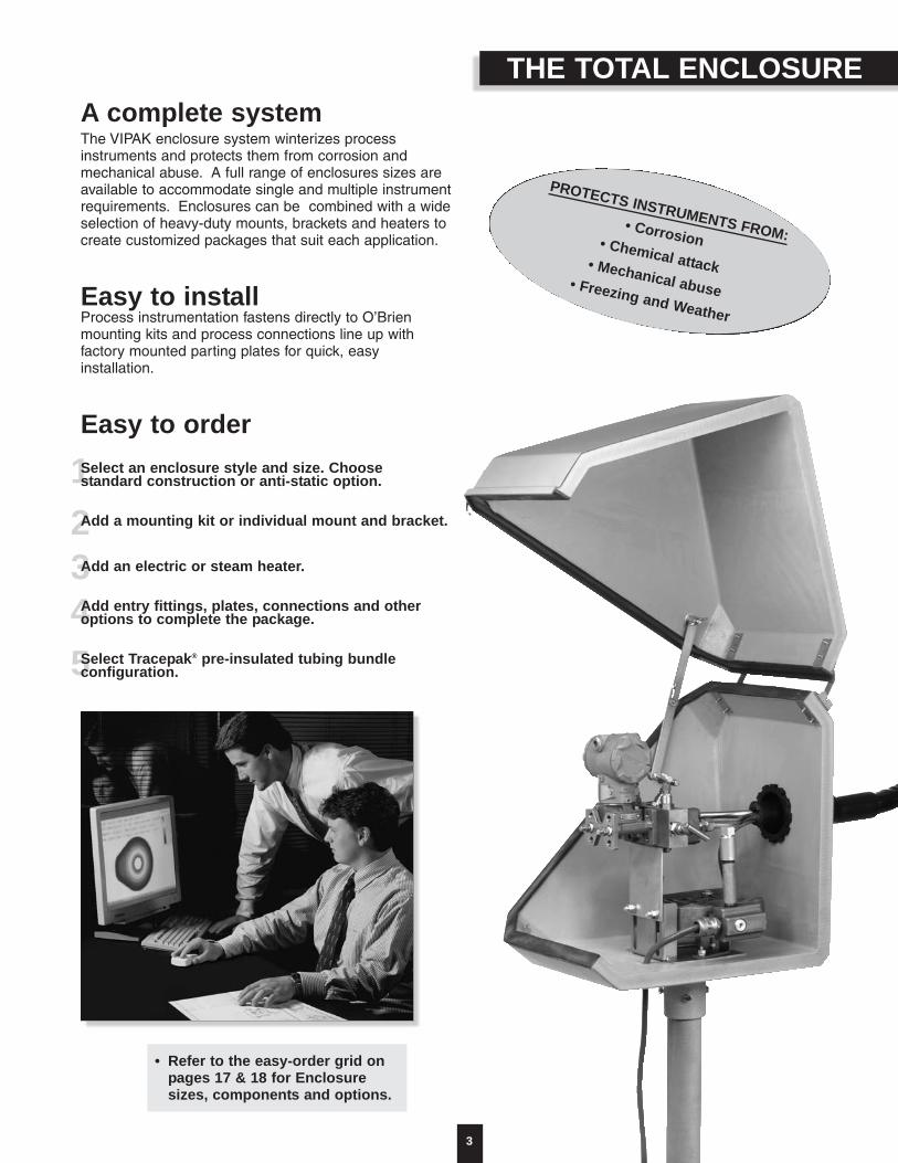
A complete systemThe VIPAK enclosure system winterizes process instruments and protects them from corrosion andmechanical abuse. A full range of enclosures sizes areavailable to accommodate single and multiple instrumentrequirements. Enclosures can be combined with a wideselection of heavy-duty mounts, brackets and heaters tocreate customized packages that suit each application.
Easy to installProcess instrumentation fastens directly to O’Brienmounting kits and process connections line up with factory mounted parting plates for quick, easy installation.
Easy to orderSelect an enclosure style and size. Choose standard construction or anti-static option.
Add a mounting kit or individual mount and bracket.
Add an electric or steam heater.
Add entry fittings, plates, connections and otheroptions to complete the package.
Select Tracepak® pre-insulated tubing bundle configuration.
PROTECTS INSTRUMENTS FROM:• Corrosion• Chemical attack • Mechanical abuse• Freezing and Weather
THE TOTAL ENCLOSURE
3
• Refer to the easy-order grid onpages 17 & 18 for Enclosuresizes, components and options.

ENCLOSURE FEATURES
4
Impact resistantTo EN50014 / BS5501VIPAK’s rigid ABS shell forms a structural bond withmedium density urethane foam insulation to provide adurable enclosure that remains impact resistant for years,even at low ambient temperatures.
Protection to -60°FVIPAK’s ABS shell and 1" thick wall of urethane insulation
combined with O’Brien heaters provide freeze protectionat temperatures as low as -60°F (-50°C) with a 25 mph
(40 kph) wind.
Metal-to-Metal SupportVIPAK’s unique thru-bolt construction,with metal spacers between the enclosuremount and the instrument bracket, providesa solid support for instruments andaccessories.
OptionalIP66 Rating
Anti-staticOptional per
EN50014 / BS5501
Corrosion & UV resistant ABS shell
Insulation 1" (25mm) thickABS/Urethane composite
Fire retardant Per IEC707 /ISO1210 / BS476
Factory installed accessories -heaters, windows, mounts, bracketry
Standard Configuration
Trakmount
Weather protectionUp to IP66
Parting lines are protected by amolded flange and sealed with
closed cell neoprene gasket.Windows are sealed with
silicone adhesive to guarantee a weather-tight
enclosure.
Heavy duty SShinges & latchesCustom designed hinges andlatches eliminate binding andallow the door or lid to beremoved easily.
5
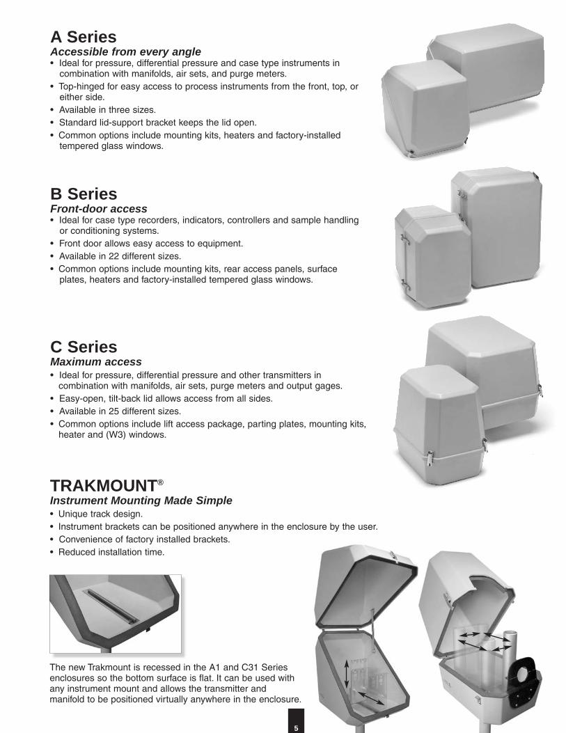
C SeriesMaximum access• Ideal for pressure, differential pressure and other transmitters in
combination with manifolds, air sets, purge meters and output gages.• Easy-open, tilt-back lid allows access from all sides.• Available in 25 different sizes.• Common options include lift access package, parting plates, mounting kits,
heater and (W3) windows.
B SeriesFront-door access• Ideal for case type recorders, indicators, controllers and sample handling
or conditioning systems.• Front door allows easy access to equipment.• Available in 22 different sizes.• Common options include mounting kits, rear access panels, surface
plates, heaters and factory-installed tempered glass windows.
A SeriesAccessible from every angle• Ideal for pressure, differential pressure and case type instruments in
combination with manifolds, air sets, and purge meters.• Top-hinged for easy access to process instruments from the front, top, or
either side.• Available in three sizes.• Standard lid-support bracket keeps the lid open.• Common options include mounting kits, heaters and factory-installed
tempered glass windows.
The new Trakmount is recessed in the A1 and C31 Seriesenclosures so the bottom surface is flat. It can be used withany instrument mount and allows the transmitter andmanifold to be positioned virtually anywhere in the enclosure.
TRAKMOUNT®
Instrument Mounting Made Simple• Unique track design.• Instrument brackets can be positioned anywhere in the enclosure by the user.• Convenience of factory installed brackets.• Reduced installation time.
MOUNTING KITS
6
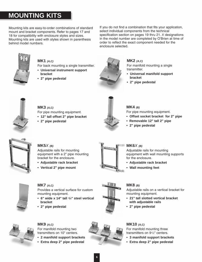
Mounting kits are easy-to-order combinations of standardmount and bracket components. Refer to pages 17 and18 for compatibility with enclosure styles and sizes.Mounting kits are used with styles shown in parenthesisbehind model numbers.
If you do not find a combination that fits your application,select individual components from the technicalspecification section on pages 19 thru 21. X designationsin the model number are completed by O’Brien at time oforder to reflect the exact component needed for theenclosure selected.
MK3 (A,C)For pipe mounting equipment.• 12" tall offset 2" pipe bracket• 2" pipe pedestal
MK5X (B)Adjustable rails for mountingequipment with a 2" pipe mountingbracket for the enclosure.• Adjustable rack bracket• Vertical 2" pipe mount
MK7 (A,C)Provides a vertical surface for custommounting equipment.• 6" wide x 14" tall 1/4" steel vertical
bracket• 2" pipe pedestal
MK4 (B)For pipe mounting equipment.• Offset socket bracket for 2" pipe• Removable 12" tall 2" pipe • 2" pipe pedestal
MK2 (A,C)For manifold mounting a singletransmitter.• Universal manifold support
bracket• 2" pipe pedestal
MK6X (B)Adjustable rails for mountingequipment with wall mounting supportsfor the enclosure.• Adjustable rack bracket• Wall mounting feet
MK8 (B)Adjustable rails on a vertical bracket formounting equipment.• 21" tall slotted vertical bracket
with adjustable rails• 2" pipe pedestal
MK9 (A,C)For manifold mounting two transmitters on 10" centers.• 2 manifold support brackets• Extra deep 2" pipe pedestal
MK10 (A,C)For manifold mounting threetransmitters on 91/2" centers.• 3 manifold support brackets• Extra deep 2" pipe pedestal
MK1 (A,C)For back mounting a single transmitter.• Universal instrument support
bracket• 2" pipe pedestal
7
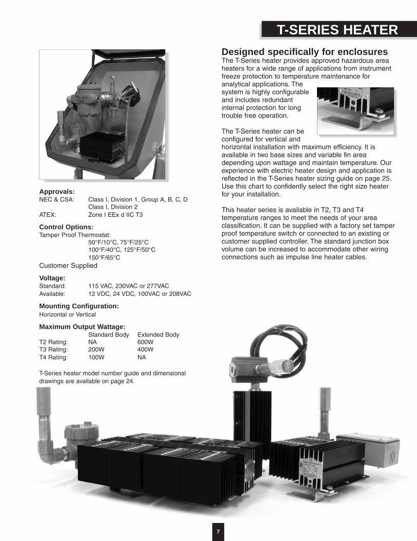
T-SERIES HEATERDesigned specifically for enclosuresThe T-Series heater provides approved hazardous areaheaters for a wide range of applications from instrumentfreeze protection to temperature maintenance foranalytical applications. Thesystem is highly configurableand includes redundantinternal protection for longtrouble free operation.
The T-Series heater can beconfigured for vertical andhorizontal installation with maximum efficiency. It isavailable in two base sizes and variable fin areadepending upon wattage and maintain temperature. Ourexperience with electric heater design and application isreflected in the T-Series heater sizing guide on page 25.Use this chart to confidently select the right size heaterfor your installation.
This heater series is available in T2, T3 and T4temperature ranges to meet the needs of your areaclassification. It can be supplied with a factory set tamperproof temperature switch or connected to an existing orcustomer supplied controller. The standard junction boxvolume can be increased to accommodate other wiringconnections such as impulse line heater cables.
Approvals:NEC & CSA: Class I, Division 1, Group A, B, C, D
Class I, Division 2ATEX: Zone I EEx d IIC T3
Control Options:Tamper Proof Thermostat:
50°F/10°C, 75°F/25°C100°F/40°C, 125°F/50°C150°F/65°C
Customer Supplied
Voltage:Standard: 115 VAC, 230VAC or 277VACAvailable: 12 VDC, 24 VDC, 100VAC or 208VAC
Mounting Configuration: Horizontal or Vertical
Maximum Output Wattage:Standard Body Extended Body
T2 Rating: NA 600WT3 Rating: 200W 400WT4 Rating: 100W NA
T-Series heater model number guide and dimensionaldrawings are available on page 24.

STEAM HEATERS
8
Six sizesWith a choice of six sizes you can select a steam heaterthat will provide freeze protection in the winter withoutoverheating the instrument in the summer.
Our experience with steam heater design and applicationis reflected in the heater sizing guide on page 26. Usethis chart to confidently select the right size heater foryour installation.
Freeze protection or temperaturemaintenanceThese heaters have been thoroughly tested in our in-house environmental chamber to verify designcalculations so that reliable predictions can be made forboth low and high ambient conditions.
If you need to maintain precise temperatures you can usethe heater control valve (HCV) to control the enclosuretemperature. It is available with standard 50°F (10°C) and100°F (40°C) set-points. It can also be ordered for specialset-point requirements.
Corrosion resistant and efficientConstructed from stainless steel tubing and carbon steelfins, each unit is coated with a nickel-chrome alloy afterassembly. O’Brien steam heaters combine corrosionresistance and heat transfer efficiency in one unit.
Simple connections and installationStainless steel mounting hardware is standard with allsteam heaters. They fasten the heater to the instrumentmounting bracket in the enclosure. The U-bend shape ofthe heater simplifies connecting the steam supply andcondensate return to the 3/8" NPT fittings.

CONNECTIONS AND OPTIONS
LPD2 Combination Power Connection KitsLPD2 kits provide a single power connection point for the enclosureheater and TRACEPAK tracer. They use FM approved and CSAcertified Division 2 components and feature an external junction box.(See pg. 21 for complete model number selection.)
IPK1 Instrumentpower/signal
connection kitThis option brings instrument power
and signal wires to the outside ofthe enclosure. It includes a 1/2" NPT
instrument connection, 24" liquidtight flexible metal conduit, and a
metallized plate with a 1/2" NPTconnection for the outside of
the enclosure.
“Y” and “T” Power Connection Kitsare electric heater options
For installations that don’t require an outside junction box, the Y andT kit heater options provide an economical and compact power
connection for the TRACEPAK tracer.
The Y kit is FM approved and CSA certified for Class I Division 2.
The T kit (not shown) is CSA certified for Class I Division 1 locations.
ES Heat-Shrink Entry Seals for tubingbundles These waterproof entry seals have a heat-shrinkable boot atone end and a mounting assembly at the other. They mountdirectly to the wall of the enclosure or can be supplied withoptional plates. The ES fittings will fit TRACEPAK tubingbundles from 3/4" to 23/4" (19-70 mm) OD.

CONNECTIONS AND OPTIONS
10
Options Enclosures can be customized for individual applications by adding options:• Tempered glass windows • Lid supports • Blow out discs• Locking latches • Access doors • EDPM latches• Drains • SS handlesFor an expanded list of mounting hardware, brackets and optional components, refer to pages 22 & 23.
Parting plate
Surface and parting line platesParting plates (PP, SPP, DPPT, DSPPT) are used with “C” style enclosures to bringprocess connections through the wall of the enclosure 2" above the parting line. Surface plates (4SP-NOT SHOWN) are used to bring connection lines through thewall of the box.
To make your installation job easier, Parting plates and Surface plates can besupplied predrilled to your specificationsor split in half.
Tubing and signal lines can be installeddirectly through the wall of theenclosure by drilling appropriate sizeholes.
The ABS shell is strong enough tomount bulkhead fittings directly to thewall of the enclosure. However, youmust use plate options when mountingfittings for steam supply or return lines. Direct mounted
bulkhead fittingsSRG Grommets

Sample transport bundles foranalyzer applications• Factory installed sensors for precise temperature
control.• Wide range of common and specialty tube materials
and sizes:• welded and seamless SS • Teflon®
• Hastelloy® • Incoloy®
• Super-Duplex • silica lined• Improved sample transport tubes from O’Brien that
reduce or eliminate the problems of long dry-down times and adsorption / desorption.
Anywhere small diameter tubing is used and you need toprovide insulation, freeze protection or temperaturemaintenance, a manufactured tubing bundle will savetime and money as well as reducing maintenance costsand improving performance.
11
Hastelloy® is a registered trademark of Haynes International.Incoloy® is a registered trademark of INCO Alloys International, INC.Teflon® is a registered trademark of IE DuPont DeNemors Corporation.
More information on preinsulated tubing bundles is available at www.tubing bundle.com and in the O’Brien Tracepak Brochure. An engineered, pre-traced and pre-insulated tubing bundle system.
TRACEPAK
Tracepak is part of the O’Briencomplete instrument winterizing andtemperature maintenance solution. Tracepak tubing bundle offers an effective solution to freezing, dew point, component drop out and viscositycontrol problems in instrument impulse lines, analyzersample transport lines and small diameter process lines.
Typical Applications:• IMPULSE LINES for flow, pressure, level transmitters,
pressure switches, controllers. • SAMPLE LINES for process and emissions analyzers,
chromatographs.• PROCESS LINES, steam supply, condensate return,
water purge, chemical feed, instrument air lines.
Choose electric traced lines, steam traced lines withheavy or light tracing, or a single pre-insulated line forsteam supply and condensate return.
The economical alternative to fieldfabrication• Maintenance free.• Save time during engineering and design.• Ensures consistent, repeatable performance.• FEA (finite element analysis) verified designs.
Parallel configuration makes fieldinstallation easy• Bending radius as short as 8" (200mm).• Easy installation of process and instrument
connections• Tubes will stay round and ready to be fitted
in a compression type fitting.• One pass, one craft installation.
Standard materials reduce sources forchloride stress corrosion of SS tubes• Low chloride insulation.• Two jacket materials:
TPU - contains no chlorides, eliminates possibility of jacket causing stress corrosion.SV47 - low temperature polyvinyl chloride for economical weather barrier.
Designed for your application• Temperature maintenance up to 650°F (340°C).• Withstand a high temperature blowdown of 1100°F
(600°C).• Freeze protection designs do not require
expensive temperature controllers.• Factory installed temperature sensors.• Multiple tubes for process lines and calibration gas.• Communication wires and power wiring, steam or
electric tracing.
APPLICATIONS
12
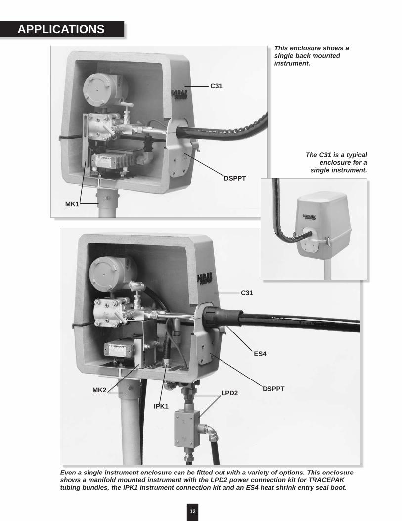
This enclosure shows asingle back mountedinstrument.
Even a single instrument enclosure can be fitted out with a variety of options. This enclosureshows a manifold mounted instrument with the LPD2 power connection kit for TRACEPAKtubing bundles, the IPK1 instrument connection kit and an ES4 heat shrink entry seal boot.
C31
DSPPT
ES4
LPD2
IPK1
MK2
C31
DSPPT
MK1
The C31 is a typicalenclosure for a
single instrument.
13
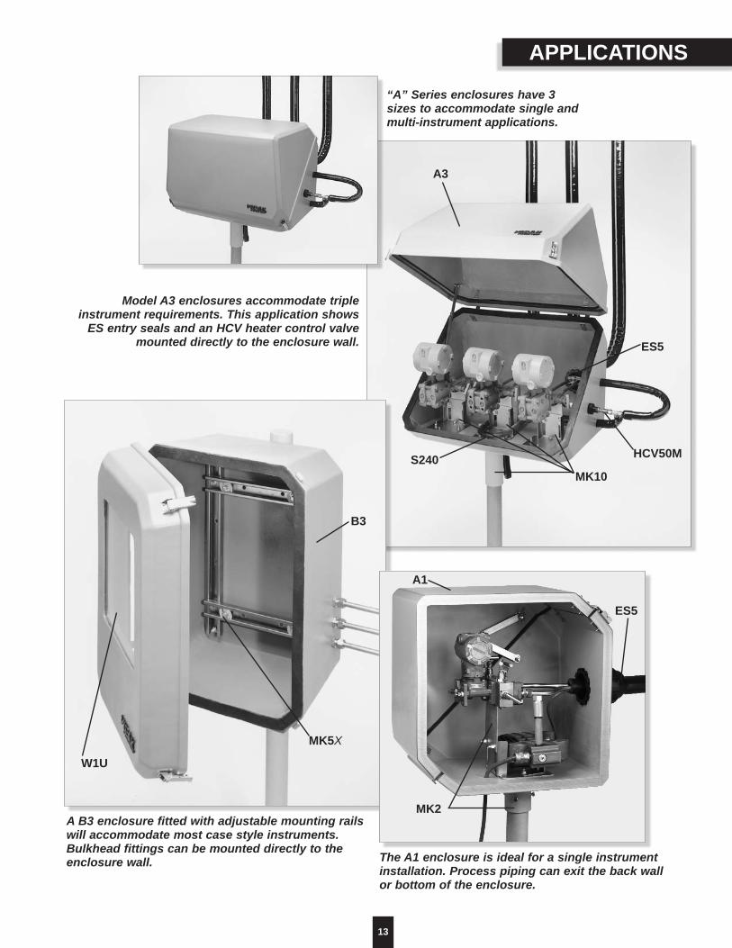
APPLICATIONS
“A” Series enclosures have 3sizes to accommodate single andmulti-instrument applications.
Model A3 enclosures accommodate tripleinstrument requirements. This application shows
ES entry seals and an HCV heater control valvemounted directly to the enclosure wall.
A3
ES5
HCV50M
MK10S240
A B3 enclosure fitted with adjustable mounting railswill accommodate most case style instruments.Bulkhead fittings can be mounted directly to theenclosure wall.
W1U
MK5X
B3
The A1 enclosure is ideal for a single instrumentinstallation. Process piping can exit the back wallor bottom of the enclosure.
A1
MK2
ES5

14
Four sizes - SUNSHADE provides protection for singleor multiple instruments, preventing instrument calibrationdrift due to temperature changes caused by solarradiation.
Mechanical protection - SUNSHADE will shieldinstruments from the sun and provide partial protectionfrom falling objects, rain, snow, and wind blown sand.
UV and corrosion resistant - The blended ABS materialhas excellent UV and corrosion resistance.
Easy access to instruments - SUNSHADE mounts to astandard 2"pipe stand and can be removed easily for fullinstrument access.
SUNSHADEMaintains process accuracy by shielding instrumentation from solar heat gain
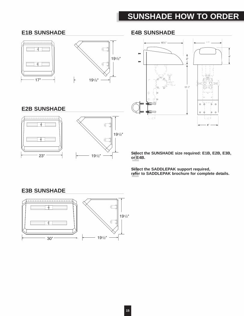
E4 SUNSHADEThe E4 SUNSHADE features a design that is
stackable to minimize shipping costs,lightweight, impact resistant, and UV resistant.
15
E1B SUNSHADE
12Select the SUNSHADE size required: E1B, E2B, E3B,or E4B.
Select the SADDLEPAK support required, refer to SADDLEPAK brochure for complete details.
SUNSHADE HOW TO ORDER
E2B SUNSHADE
E3B SUNSHADE
E4B SUNSHADE153/4"
4"
171/2"
11"
6"
8"
191/2"
23"
17"
30"
191/2"
191/2"
191/2"
191/2"
191/2"
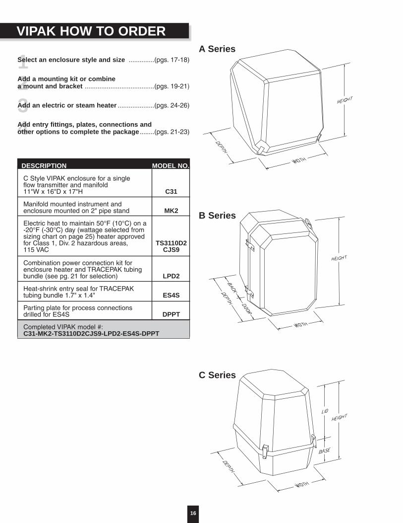
VIPAK HOW TO ORDER
16
1234
Select an enclosure style and size ..............(pgs. 17-18)
Add a mounting kit or combine a mount and bracket ......................................(pgs. 19-21)
Add an electric or steam heater ....................(pgs. 24-26)
Add entry fittings, plates, connections and other options to complete the package ........(pgs. 21-23)
DESCRIPTION MODEL NO.
C Style VIPAK enclosure for a single flow transmitter and manifold11"W x 16"D x 17"H C31
Manifold mounted instrument andenclosure mounted on 2" pipe stand MK2
Electric heat to maintain 50°F (10°C) on a -20°F (-30°C) day (wattage selected from sizing chart on page 25) heater approved for Class 1, Div. 2 hazardous areas, TS3110D2115 VAC CJS9
Combination power connection kit for enclosure heater and TRACEPAK tubing bundle (see pg. 21 for selection) LPD2
Heat-shrink entry seal for TRACEPAK tubing bundle 1.7" x 1.4" ES4S
Parting plate for process connections drilled for ES4S DPPT
Completed VIPAK model #:C31-MK2-TS3110D2CJS9-LPD2-ES4S-DPPT
A Series
B Series
C Series
17
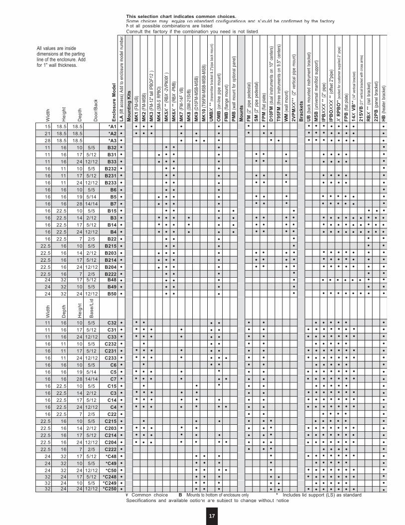
This selection chart indicates common choices. Some choices may require nonstandard configurations and should be confirmed by the factory. Not all possible combinations are listed. Consult the factory if the combination you need is not listed.
Wid
th
Hei
ght
Dep
th
Doo
r/Bac
k
Encl
osur
e M
odel
LA
(lift
acce
ss) A
dd to
enc
losur
e mo
del n
umbe
r. M
ount
ing
Kits
M
K1
(FM-
UB)
MK
2 (F
M-MS
B)
MK
3 (F
M-12
" tall
IPBO
F12
) M
K4
(SM-
S RP
BO)
MK
5 X *
* (RB
X -2
VPM X
X )
MK
6 X *
* (RB
X -P
MB)
MK
7 (F
M-14
F VB
) M
K8
(SM-
21 S V
B)
MK
9 (D
10FM
-MSB
-MSB
) M
K10
(T95
FM-M
SB-M
SB-M
SB)
UMB
X *
* (tra
nsmi
tter b
rack
et &
2"pip
e ba
ck m
ount)
OM
B (o
n-lin
e pi
pe m
ount
) FM
B (f
lange
mou
nt)
PMB
(wall
mou
nt fo
r opt
ional
pane
l) M
ount
s FM
(2" p
ipe p
edes
tal)
SM (2
" pipe
ped
esta
l) FP
M (f
lat p
late)
D
10FM
(dua
l instr
umen
ts on
10"
cen
ters)
T95F
M (t
hree
instr
umen
ts on
9.5"
cen
ters)
WM
(wall
mou
nt)
2VPM
XX
** (
2" v
ertic
al pi
pe m
ount
) B
rack
ets
UB (b
ack
moun
ted
instr
umen
t bra
cket
) M
SB (u
niver
sal m
anifo
ld su
ppor
t) IP
B X
XX
** (2
" pipe
) IP
BO
XX
X * *
(offs
et 2"
pipe)
X
RPB
O **
(sock
et fo
r cus
tomer
supp
lied
2" p
ipe)
FPB
(flat
plat
e)
14 X
VB **
(14"
vertic
al br
acke
t)
21S
VB
(21"
vertic
al br
acke
t with
cros
s arm
s)
RB X
**
(rail
brac
ket)
22P
B (p
anel
brac
ket)
HB (h
eate
r bra
cket
)
15 18.5 18.5 *A121 18.5 18.5 *A2 28 18.5 18.5 *A3 11 16 10 5/5 B32 11 16 17 5/12 B31 11 16 24 12/12 B33 16 11 10 5/5 B232 16 11 17 5/12 B231 16 11 24 12/12 B233 16 16 10 5/5 B6 16 16 19 5/14 B5 16 16 28 14/14 B7 16 22.5 10 5/5 B15 16 22.5 14 2/12 B3 16 22.5 17 5/12 B14 16 22.5 24 12/12 B4 16 22.5 7 2/5 B22
22.5 16 10 5/5 B215 22.5 16 14 2/12 B203 22.5 16 17 5/12 B214 22.5 16 24 12/12 B204 22.5 16 7 2/5 B222
24 32 17 5/12 B4824 32 10 5/5 B4924 32 24 12/12 B50
Wid
th
Dep
th
Hei
ght
Bas
e/Li
d
11 16 10 5/5 C32 11 16 17 5/12 C31 11 16 24 12/12 C33 16 11 10 5/5 C232 16 11 17 5/12 C231 16 11 24 12/12 C233 16 16 10 5/5 C6 16 16 19 5/14 C5 16 16 28 14/14 C7 16 22.5 10 5/5 C15 16 22.5 14 2/12 C3 16 22.5 17 5/12 C14 16 22.5 24 12/12 C4 16 22.5 7 2/5 C22
22.5 16 10 5/5 C215 22.5 16 14 2/12 C203 22.5 16 17 5/12 C214 22.5 16 24 12/12 C204 22.5 16 7 2/5 C222
24 32 17 5/12 *C48 24 32 10 5/5 *C49 24 32 24 12/12 *C50 32 24 17 5/12 *C248 32 24 10 5/5 *C24932 24 24 12/12 *C250
¥ - Common choice. B - M ounts to bottom of enclosure only. * - Includes lid support (LS) as standard. Specifications and available options are subject to change without notice.
•••••••••••••••••••••••••
•••••••••••••••••••••••••
••
••
••
••
•••
••
••
•••
•••
••••••••••••••••••••••
••••••••••••••••••••••
•••••••••••••••••••••••
• • •
•••
••••
••
•• •
• •
••
••
••
••
••
••
••
••
••
•••
•••
•••
•••
•
••
•••
•••
•••
•••••••
•••
•••
•••
•••
•••
•••
•••
•••
••
••
••
••
••
••
••
••
••
••
••
••
••
• ••••
•••
•••
•••
•••
•••
•••
•••
•••••
••
•••
•••
•••
•••
•••
•••••••
•••••••
• • • • • •
• • • • • •
•••
•••
••
•••
••
••
••
••
••
•
••
••
••
• • •
•
•••
••
••
• • •
••
••
••
•••
•••
••••
••••
••••••
••••••
••••••
•
•
•• •
•• •
••••••••••
•••••••
•
•
•••••••••••••••••••
•••••••••••••••••••
•••••••••••
•••
••
••
••
•••
•••
•
••
•
••••••
••••••
••••••
••••••
••••••
•
••
•
• • • •
•••
•••
•••
•••
•••
•
••
•••
•••
•••
•••
•••
•••
••
••
••
••
••
••
••
••
••
••
••
••
••
••
••
••
••
••
• • • • •
• • • • •
• • • • •
• • • • •
• • • • •• • • •
•••••••••••••••••••••••••
••••••••••
18
*A1*A2*A3B32B31B33
B232B231B233
B6B5B7
B15B3
B14B4
B22B215B203B214B204B222
B48B49B50
C32C31C33
C232C231C233
C6C5C7
C15C3
C14C4
C22C215C203C214C204C222*C48*C49*C50
*C248*C249*C250
• • •• • •• • •• • •• • •• • •• • •• • •• • •• • •• • •• • •• • •• • •• • •• • •• • •• • •• • •• • •• • •
• • •• • •• • •
• • •• • •• • •• • •• • •• • •• • •• • •• • •• • •• • •• • •• • •
• • •• • •• • •• • •
• • •• • •• • •• • •• • •• • •
• •• •• •
••••••
• •• •• •• •• •• •• •• •• •• •• •• •• •• •• •• •
•••••
• •• •
•••
•••
•
••
•
Elec
tric
Hea
ters
T St
yle
T(C
SA
pow
er c
onne
ctio
n fo
r T
RA
CE
PAK
)
Y(F
M D
iv.2
pow
er c
onne
ctio
n fo
r T
RA
CE
PAK
Con
nect
ions
LPD
2(c
ombi
natio
n po
wer
con
nect
ion
kit)
IPK
1(in
stru
men
t co
nnec
tion
kit)
OJ
(out
side
junc
tion
box)
Stea
m H
eate
rsS3
0S6
0S8
0S1
40S1
90S2
40H
CV5
0(5
0ºF
set
poin
t)
HC
V100
100º
F s
etpo
int)
Bun
dle
Entr
y Fi
tting
sES
4(0
.75"
to
1.6"
dia
.tub
ing
bund
le fi
tting
)
ES4S
ES5
(1.5
" to
2.7
5" d
ia.t
ubin
g bu
ndle
fitti
ng)
Part
ing
Plat
esPP
(par
ting
line
plat
e)
SPP
(spl
it pa
rtin
g lin
e pl
ate)
DPP
T(p
artin
g lin
e pl
ate
for
fittin
g)
DSP
PT(s
lit p
artin
g lin
e pl
ate
for
TR
AC
EPA
K)
Surf
ace
Plat
esFS
P(4
"x6"
sur
face
pla
te)
Win
dow
sW
1(1
2"x1
2")
W3
(7"d
ia.)
Oth
er O
ptio
nsPH
(non
-met
allic
har
dwar
e, li
ft ac
cess
onl
y)
DA
(acc
ess
door
)
R(d
oor/
lid r
etai
ner)
LS(li
d/do
or s
uppo
rt)
H(h
andl
e)
BO
(blo
w-o
ut d
isk)
D(d
rain
plu
g)
SK(R
TV
sea
lant
)
LL(lo
ckin
g la
tch)
PT(p
hone
lic t
ag)
Encl
osur
e M
odel
• • •• • •• • •• • •• • •• • •• • •• • •• • •• • •• • •• • •• • •• • •• • •• • •• • •• • •• • •• • •• • •
• • •• • •• • •
• • •• • •• • •• • •• • •• • •• • •• • •• • •• • •• • •• • •• • •
• • •• • •• • •• • •
• • •• • •• • •• • •• • •• • •
• • • • • • • •• • • • • • • •• • • • • • • •• • • • • •• • • • • •• • • • • •• • • • • • •• • • • • • •• • • • • • •• • • • • • •• • • • • • •• • • • • • •• • • • • • •• • • • • • •• • • • • • •• • • • • • •• • • • • • •• • • • • • • •• • • • • • • •• • • • • • • •• • • • • • • •• • • • • • • •• • • • • • • •• • • • • • • •• • • • • • • •
• • • • • • • •• • • • • • • •• • • • • • • •• • • • • • • •• • • • • • • •• • • • • • • •• • • • • • • •• • • • • • • •• • • • • • • •• • • • • • • •• • • • • • • •• • • • • • • •• • • • • • • •• • • • • •• • • • • • • •• • • • • • • •• • • • • • • •• • • • • • • •• • • • • •• • • • • • • •• • • • • • • •• • • • • • • •• • • • • • • •• • • • • • • •• • • • • • • •
• •• •• •• •• •• •• •• •• •• •• •• •• •• •• •• •• •• •• •• •• •• •• •• •• •
• •• •• •• •• •• •• •• •• •• •• •• •• •• •• •• •• •• •• •• •• •• •• •• •• •
•••••••••••••••••••••••••
•••••••••••••••••••••••••
• • • • • • • • •• • • • • • • • •• • • • • • • • •• • • • • • • •• • • • • • • •• • • • • • • •• • • • • • • •• • • • • • • •• • • • • • • •• • • • • • • • •• • • • • • • • •• • • • • • • • •• • • • • • • • •• • • • • • • • •• • • • • • • • •• • • • • • • • •• • • • • • • • •• • • • • • • • •• • • • • • • • •• • • • • • • • •• • • • • • • • •• • • • • • • • •• • • • • • • • •• • • • • • • • •• • • • • • • • •
• • • • • • • • •• • • • • • • • •• • • • • • • • •• • • • • • • • •• • • • • • • • •• • • • • • • • •• • • • • • • • •• • • • • • • • •• • • • • • • • •• • • • • • • • •• • • • • • • • •• • • • • • • • •• • • • • • • • •• • • • • • • • •• • • • • • • • •• • • • • • • • •• • • • • • • • •• • • • • • • • •• • • • • • • • •• • • • • • • • •• • • • • • • • •• • • • • • • • •• • • • • • • • •• • • • • • • • •• • • • • • • • •
•••••••••••••••••••••••••
•••••••••••••••••••••••••
• • • •• • • •
• • • •• • • •
• • • •• • • •
• • • •• • • •
• • • •• • • •
• • • •
• • • •• • • •
• • • •** - These items are sized by O'Brien depending upon enclosure and other options selected.B - Mounts to bottom of enclosure only. Zinc metallizing available - consult factory
19
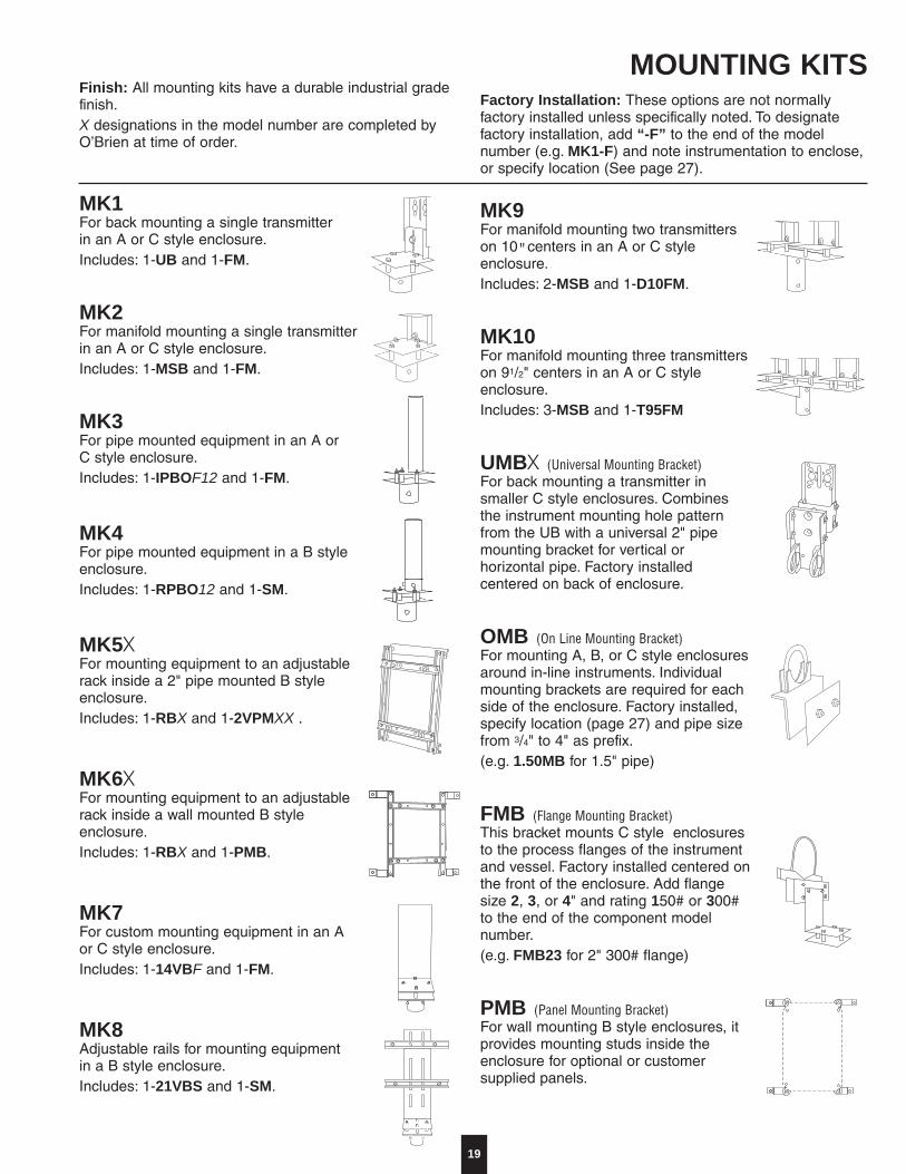
MK9For manifold mounting two transmitterson 10"centers in an A or C style enclosure.Includes: 2-MSB and 1-D10FM.
MK10For manifold mounting three transmitters on 91/2" centers in an A or C style enclosure.Includes: 3-MSB and 1-T95FM
UMBu (Universal Mounting Bracket)For back mounting a transmitter in smaller C style enclosures. Combines the instrument mounting hole pattern from the UB with a universal 2" pipe mounting bracket for vertical or horizontal pipe. Factory installed centered on back of enclosure.
OMB (On Line Mounting Bracket)For mounting A, B, or C style enclosuresaround in-line instruments. Individualmounting brackets are required for eachside of the enclosure. Factory installed,specify location (page 27) and pipe sizefrom 3/4" to 4" as prefix.(e.g. 1.50MB for 1.5" pipe)
FMB (Flange Mounting Bracket)This bracket mounts C style enclosuresto the process flanges of the instrumentand vessel. Factory installed centered onthe front of the enclosure. Add flangesize 2, 3, or 4" and rating 150# or 300#to the end of the component modelnumber.(e.g. FMB23 for 2" 300# flange)
PMB (Panel Mounting Bracket)For wall mounting B style enclosures, itprovides mounting studs inside theenclosure for optional or customersupplied panels.
Finish: All mounting kits have a durable industrial gradefinish.X designations in the model number are completed byO’Brien at time of order.
MK1For back mounting a single transmitterin an A or C style enclosure.Includes: 1-UB and 1-FM.
MK2For manifold mounting a single transmitterin an A or C style enclosure.Includes: 1-MSB and 1-FM.
MK3For pipe mounted equipment in an A orC style enclosure.Includes: 1-IPBOF12 and 1-FM.
MK4For pipe mounted equipment in a B styleenclosure.Includes: 1-RPBO12 and 1-SM.
MK5uFor mounting equipment to an adjustablerack inside a 2" pipe mounted B styleenclosure.Includes: 1-RBX and 1-2VPMXX .
MK6uFor mounting equipment to an adjustablerack inside a wall mounted B styleenclosure.Includes: 1-RBX and 1-PMB.
MK7For custom mounting equipment in an Aor C style enclosure.Includes: 1-14VBF and 1-FM.
MK8Adjustable rails for mounting equipmentin a B style enclosure.Includes: 1-21VBS and 1-SM.
MOUNTING KITSFactory Installation: These options are not normallyfactory installed unless specifically noted. To designatefactory installation, add “-F” to the end of the modelnumber (e.g. MK1-F) and note instrumentation to enclose,or specify location (See page 27).
20
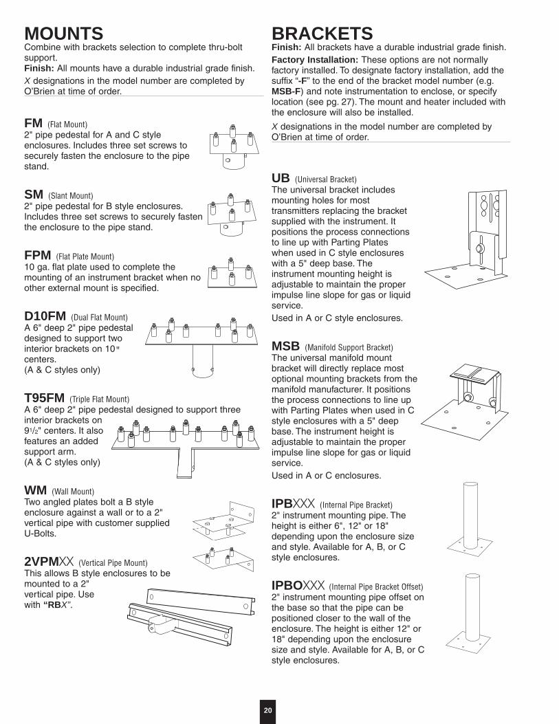
FM (Flat Mount)2" pipe pedestal for A and C styleenclosures. Includes three set screws tosecurely fasten the enclosure to the pipestand.
SM (Slant Mount)2" pipe pedestal for B style enclosures.Includes three set screws to securely fastenthe enclosure to the pipe stand.
FPM (Flat Plate Mount)10 ga. flat plate used to complete themounting of an instrument bracket when noother external mount is specified.
D10FM (Dual Flat Mount)A 6" deep 2" pipe pedestaldesigned to support twointerior brackets on 10"centers.(A & C styles only)
T95FM (Triple Flat Mount)A 6" deep 2" pipe pedestal designed to support threeinterior brackets on91/2" centers. It alsofeatures an addedsupport arm.(A & C styles only)
WM (Wall Mount)Two angled plates bolt a B styleenclosure against a wall or to a 2"vertical pipe with customer supplied U-Bolts.
2VPMuu (Vertical Pipe Mount)This allows B style enclosures to bemounted to a 2"vertical pipe. Usewith “RBX”.
MOUNTSCombine with brackets selection to complete thru-boltsupport.Finish: All mounts have a durable industrial grade finish.X designations in the model number are completed byO’Brien at time of order.
UB (Universal Bracket)The universal bracket includesmounting holes for mosttransmitters replacing the bracketsupplied with the instrument. Itpositions the process connectionsto line up with Parting Plateswhen used in C style enclosureswith a 5" deep base. Theinstrument mounting height isadjustable to maintain the properimpulse line slope for gas or liquidservice.Used in A or C style enclosures.
MSB (Manifold Support Bracket)The universal manifold mountbracket will directly replace mostoptional mounting brackets from themanifold manufacturer. It positionsthe process connections to line upwith Parting Plates when used in Cstyle enclosures with a 5" deepbase. The instrument height isadjustable to maintain the properimpulse line slope for gas or liquidservice.Used in A or C enclosures.
IPBuuu (Internal Pipe Bracket)2" instrument mounting pipe. Theheight is either 6", 12" or 18"depending upon the enclosure sizeand style. Available for A, B, or Cstyle enclosures.
IPBOuuu (Internal Pipe Bracket Offset)2" instrument mounting pipe offset onthe base so that the pipe can bepositioned closer to the wall of theenclosure. The height is either 12" or18" depending upon the enclosuresize and style. Available for A, B, or Cstyle enclosures.
BRACKETSFinish: All brackets have a durable industrial grade finish.Factory Installation: These options are not normallyfactory installed. To designate factory installation, add thesuffix “-F” to the end of the bracket model number (e.g.MSB-F) and note instrumentation to enclose, or specifylocation (see pg. 27). The mount and heater included withthe enclosure will also be installed.
X designations in the model number are completed byO’Brien at time of order.
21
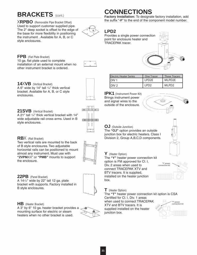
LPD2 Provides a single power connection point for enclosure heater and TRACEPAK tracer.
IPK1 (Instrument Power Kit)Brings instrument power and signal wires to the outside of the enclosure.
OJ (Outside Junction)The “OJ” option provides an outsidejunction box for electric heaters. Class IDivision 2, Group A,B,C,D components.
Y (Heater Option)The “Y” heater power connection kitoption is FM approved for Cl. I,Div. 2 areas when used toconnect TRACEPAK XTV andBTV tracers. It is supplied,installed on the heater junctionbox.
T (Heater Option)The “T” heater power connection kit option is CSACertified for Cl. I, Div. 1 areaswhen used to connect TRACEPAKXTV and BTV tracers. It issupplied installed on the heaterjunction box.
uRPBO (Removable Pipe Bracket Offset)Used to support customer supplied pipe.The 2" deep socket is offset to the edge ofthe base for more flexibility in positioningthe instrument . Available for A, B, or Cstyle enclosures.
FPB (Flat Plate Bracket)10 ga. flat plate used to completeinstallation of an external mount when noother instrument bracket is ordered.
14uVB (Vertical Bracket)A 6" wide by 14" tall 1/4" thick verticalbracket. Available for A, B, or C styleenclosures.
21SVB (Vertical Bracket)A 21" tall 1/4" thick vertical bracket with 14"wide adjustable rail cross arms. Used in Bstyle enclosures.
RBu (Rail Bracket)Two vertical rails are mounted to the backof B style enclosures. Two adjustablehorizontal rails can be positioned to mountalmost any instrument. Must use with“2VPMXX” or “PMB” mounts to supportthe enclosure.
22PB (Panel Bracket)A 141/4" wide by 22" tall 12 ga. platebracket with supports. Factory installed inB style enclosures.
HB (Heater Bracket)A 3" by 6" 10 ga. heater bracket provides amounting surface for electric or steamheaters when no other bracket is used.
CONNECTIONSFactory Installation: To designate factory installation, addthe suffix “-F” to the end of the component model number.
Three
DIV 1
DIV 2
M
M
BRACKETS EÅçåíKF
22
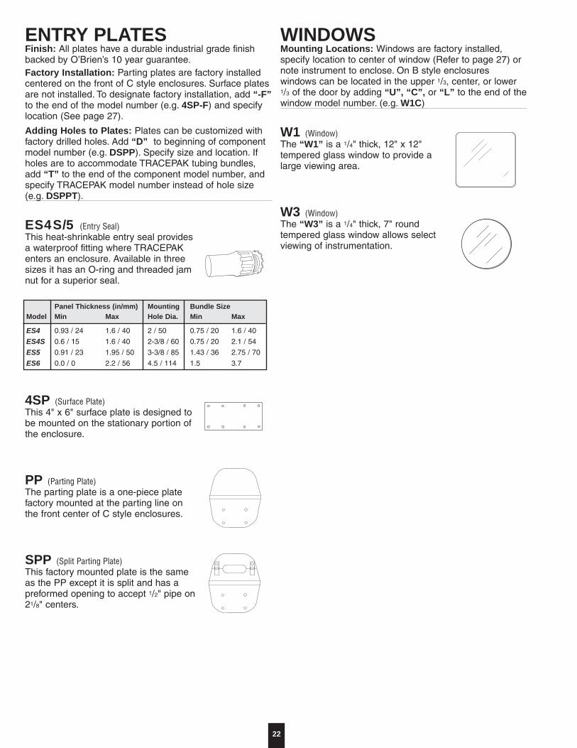
ENTRY PLATESFinish: All plates have a durable industrial grade finishbacked by O’Brien’s 10 year guarantee.Factory Installation: Parting plates are factory installedcentered on the front of C style enclosures. Surface platesare not installed. To designate factory installation, add “-F”to the end of the model number (e.g. 4SP-F) and specifylocation (See page 27).
Adding Holes to Plates: Plates can be customized withfactory drilled holes. Add “D” to beginning of componentmodel number (e.g. DSPP). Specify size and location. Ifholes are to accommodate TRACEPAK tubing bundles,add “T” to the end of the component model number, andspecify TRACEPAK model number instead of hole size(e.g. DSPPT).
ES4S/5 (Entry Seal)This heat-shrinkable entry seal providesa waterproof fitting where TRACEPAKenters an enclosure. Available in threesizes it has an O-ring and threaded jamnut for a superior seal.
4SP (Surface Plate)This 4" x 6" surface plate is designed tobe mounted on the stationary portion ofthe enclosure.
PP (Parting Plate)The parting plate is a one-piece platefactory mounted at the parting line onthe front center of C style enclosures.
SPP (Split Parting Plate)This factory mounted plate is the sameas the PP except it is split and has apreformed opening to accept 1/2" pipe on21/8" centers.
WINDOWSMounting Locations: Windows are factory installed,specify location to center of window (Refer to page 27) ornote instrument to enclose. On B style enclosureswindows can be located in the upper 1/3, center, or lower1/3 of the door by adding “U”, “C”, or “L” to the end of thewindow model number. (e.g. W1C)
W1 (Window)The “W1” is a 1/4" thick, 12" x 12"tempered glass window to provide alarge viewing area.
W3 (Window)The “W3” is a 1/4" thick, 7" roundtempered glass window allows selectviewing of instrumentation.
Panel Thickness (in/mm) Mounting Bundle SizeModel Min Max Hole Dia. Min Max
ES4 0.93 / 24 1.6 / 40 2 / 50 0.75 / 20 1.6 / 40
ES4S 0.6 / 15 1.6 / 40 2-3/8 / 60 0.75 / 20 2.1 / 54
ES5 0.91 / 23 1.95 / 50 3-3/8 / 85 1.43 / 36 2.75 / 70
ES6 0.0 / 0 2.2 / 56 4.5 / 114 1.5 3.7
23
OTHER OPTIONS
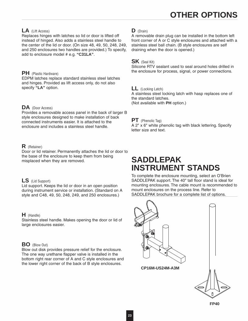
LA (Lift Access)Replaces hinges with latches so lid or door is lifted offinstead of hinged. Also adds a stainless steel handle tothe center of the lid or door. (On size 48, 49, 50, 248, 249,and 250 enclosures two handles are provided.) To specify,add to enclosure model # e.g. “C31LA”.
PH (Plastic Hardware)EDPM latches replace standard stainless steel latchesand hinges. Provided as lift access only, do not alsospecify “LA” option.
DA (Door Access)Provides a removable access panel in the back of larger Bstyle enclosures designed to make installation of backconnected instruments easier. It is attached to theenclosure and includes a stainless steel handle.
R (Retainer)Door or lid retainer. Permanently attaches the lid or door tothe base of the enclosure to keep them from beingmisplaced when they are removed.
LS (Lid Support)Lid support. Keeps the lid or door in an open positionduring instrument service or installation. (Standard on Astyle and C48, 49, 50, 248, 249, and 250 enclosures.)
H (Handle)Stainless steel handle. Makes opening the door or lid oflarge enclosures easier.
BO (Blow Out)Blow out disk provides pressure relief for the enclosure.The one way urethane flapper valve is installed in thebottom right rear corner of A and C style enclosures andthe lower right corner of the back of B style enclosures.
SADDLEPAKINSTRUMENT STANDSTo complete the enclosure mounting, select an O’BrienSADDLEPAK support. The 40" tall floor stand is ideal formounting enclosures. The cable mount is recommended tomount enclosures on the process line. Refer toSADDLEPAK brochure for a complete list of options.
CP16M-US24M-A3M
FP40
D (Drain)A removable drain plug can be installed in the bottom leftfront corner of A or C style enclosures and attached with astainless steel ball chain. (B style enclosures are selfdraining when the door is opened.)
SK (Seal Kit)Silicone RTV sealant used to seal around holes drilled inthe enclosure for process, signal, or power connections.
LL (Locking Latch)A stainless steel locking latch with hasp replaces one ofthe standard latches.(Not available with PH option.)
PT (Phenolic Tag)A 2" x 6" white phenolic tag with black lettering. Specifyletter size and text.
24
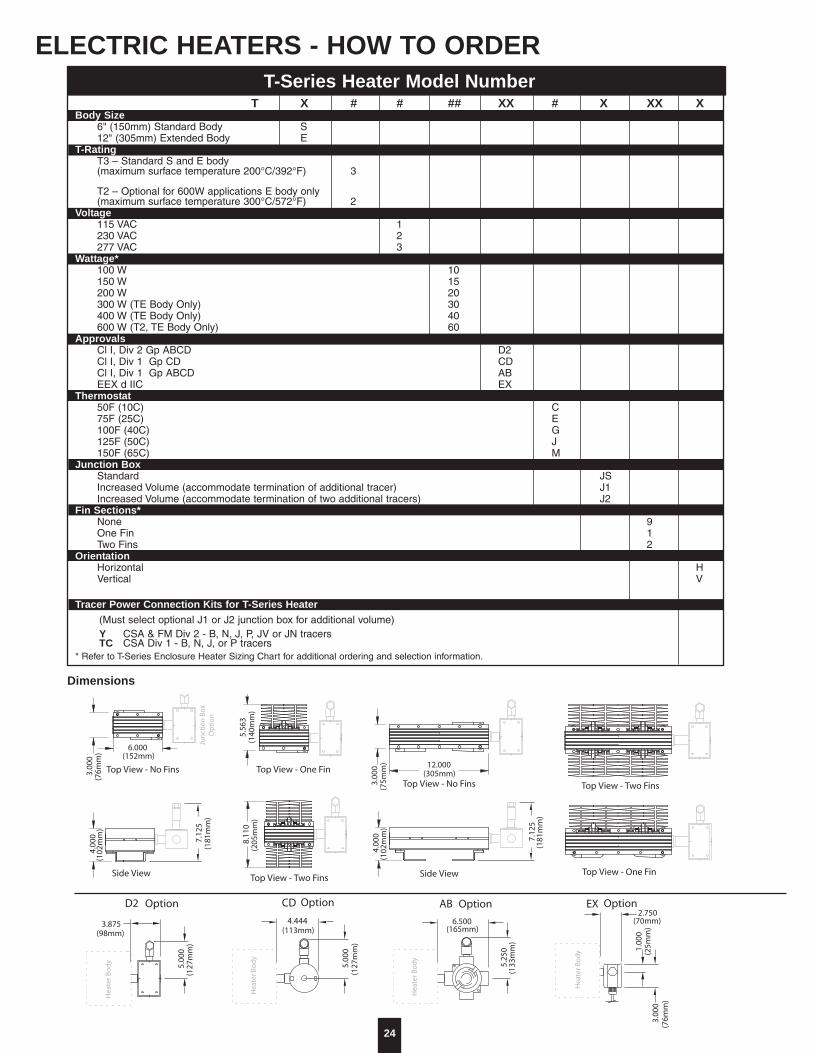
ELECTRIC HEATERS - HOW TO ORDERT-Series Heater Model Number
Dimensions
(Must select optional J1 or J2 junction box for additional volume)Y CSA & FM Div 2 - B, N, J, P, JV or JN tracersTC CSA Div 1 - B, N, J, or P tracers
T X # # ## XX # X XX XBody Size
6" (150mm) Standard Body S12" (305mm) Extended Body E
T-RatingT3 – Standard S and E body(maximum surface temperature 200°C/392°F) 3
T2 – Optional for 600W applications E body only(maximum surface temperature 300°C/572°F) 2
Voltage115 VAC 1230 VAC 2277 VAC 3
Wattage*100 W 10150 W 15200 W 20300 W (TE Body Only) 30400 W (TE Body Only) 40600 W (T2, TE Body Only) 60
ApprovalsCl I, Div 2 Gp ABCD D2Cl I, Div 1 Gp CD CDCl I, Div 1 Gp ABCD ABEEX d IIC EX
Thermostat50F (10C) C75F (25C) E100F (40C) G125F (50C) J150F (65C) M
Junction BoxStandard JSIncreased Volume (accommodate termination of additional tracer) J1Increased Volume (accommodate termination of two additional tracers) J2
Fin Sections*None 9One Fin 1Two Fins 2
OrientationHorizontal HVertical V
Tracer Power Connection Kits for T-Series Heater
* Refer to T-Series Enclosure Heater Sizing Chart for additional ordering and selection information.
25
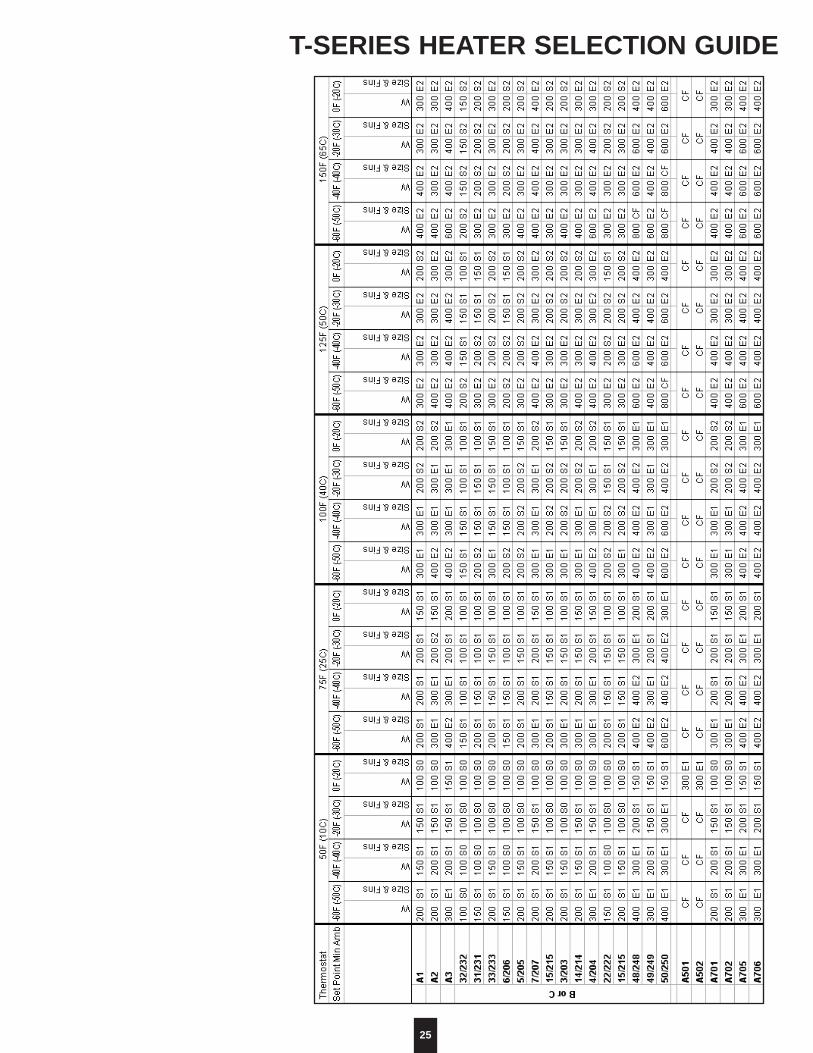
T-SERIES HEATER SELECTION GUIDE

26
InstructionsAll heating systems are designed to maintain 50°F underthe given conditions.
• Check physical size limitations within enclosure.(Refer to the selection grid on pages 17-18.)
S80 26"152
3/8"Connectingtubing length
Heater ModelNumber
Enclosure temp. at 110°F ambient
HCV50/100Heater control valves for 50°F and 100°F setpoints.
LENG
TH
5"
6"
3/8" FNPT
7/8" 1 1/2"StainlessSteel
mounting
suppliedbrackets
Style may vary
STEAM HEATER SELECTION GUIDE
27
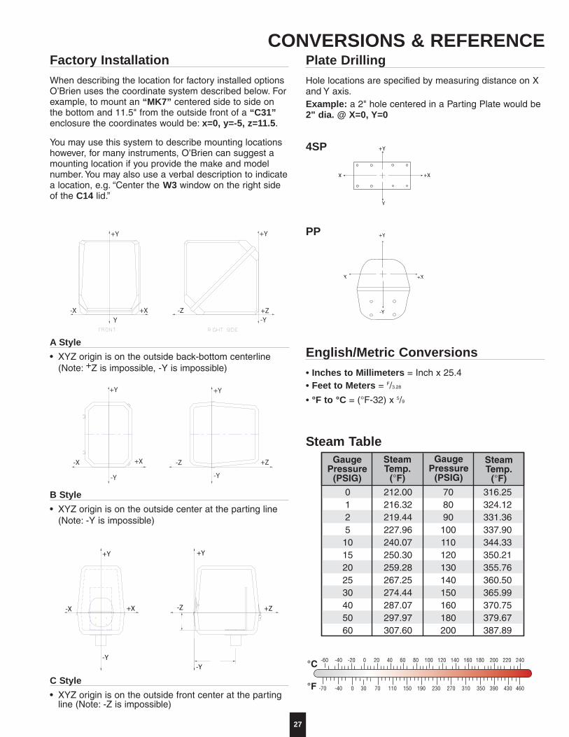
Factory InstallationWhen describing the location for factory installed optionsO’Brien uses the coordinate system described below. Forexample, to mount an “MK7” centered side to side onthe bottom and 11.5" from the outside front of a “C31”enclosure the coordinates would be: x=0, y=-5, z=11.5.
You may use this system to describe mounting locationshowever, for many instruments, O’Brien can suggest amounting location if you provide the make and modelnumber. You may also use a verbal description to indicatea location, e.g. “Center the W3 window on the right sideof the C14 lid.”
A Style• XYZ origin is on the outside back-bottom centerline
(Note: +Z is impossible, -Y is impossible)
+Y
-Y
X +X
4SP
PP
+XX
+Y
-Y
Plate DrillingHole locations are specified by measuring distance on Xand Y axis.Example: a 2" hole centered in a Parting Plate would be2" dia. @ X=0, Y=0
English/Metric Conversions• Inches to Millimeters = Inch x 25.4• Feet to Meters = F/3.28
• °F to °C = (°F-32) x 5/9
Steam Table
+Y
+X-X
-Y
-Z
+Y
-Y
+Z
B Style• XYZ origin is on the outside center at the parting line
(Note: -Y is impossible)
C Style• XYZ origin is on the outside front center at the parting
line (Note: -Z is impossible)
CONVERSIONS & REFERENCE

SA
DD
LEP
AK
FLE
XP
AK
Total Solutionl∞_êáÉå éêçÇìÅíë ~åÇ ëçäìíáçåëáãéêçîÉ áåëíêìãÉåí ~ÅÅìê~ÅóKlìê íçí~ä ÉåÖáåÉÉêáåÖ é~Åâ~ÖÉ ïáääêÉÇìÅÉ ÑáÉäÇ áåëí~ää~íáçå Åçëíë ~åÇéêçîáÇÉ ~ ÇÉéÉåÇ~ÄäÉ ëçäìíáçå Ñçêóçìê åÉÉÇëK
VIP
AK
TR
AC
EP
AK
ISO 9001 Unparalleled Quality`ÉêíáÑáÉÇ íç ÅìêêÉåí fpl VMMN ëí~åÇ~êÇëK
l∞_êáÉå∞ë ~ÇÜÉêÉåÅÉ íç êÉÅçÖåáòÉÇáåíÉêå~íáçå~ä ëí~åÇ~êÇë áë óçìêëíêçåÖÉëí ~ëëìê~åÅÉ çÑ çìê èì~äáíóK
HE
AT
PA
K
Customer Servicel∞_êáÉå∞ë êÉéìí~íáçå ~ë ~ ÅìëíçãÉêçêáÉåíÉÇ éêçÄäÉã ëçäîÉê Ü~ë ÄÉÉåäçåÖ êÉÅçÖåáòÉÇK
lìê ÅìëíçãÉêJçêáÉåíÉÇ ~ééêç~ÅÜçÑÑÉêëW• êÉëéçåëáîÉI âåçïäÉÇÖÉ~ÄäÉ
éÉêëçååÉä• ìåé~ê~ääÉäÉÇ ÇÉäáîÉêó ëÉêîáÅÉ• ÇÉéÉåÇ~ÄäÉI íÉëíÉÇ êÉëìäíë çÑ ~ää
éêçÇìÅí äáåÉë• çåJäáåÉ çêÇÉê ëí~íìë ~åÇ
ëÜáéãÉåí íê~ÅâáåÖK
Specifications subject to change without notice.
Offices
O’Brien Corporation1900 Crystal Industrial Ct.St. Louis, MO 63114Ph: 314/236-2020Fax: 314/236-2080
Mallekotstraat 65B 2500 Lier BelgiumPh: (+32) 3 491 9875Fax: (+32) 3 491 9876
©20
07 O
’Brie
n C
orpo
ratio
n •
Bul
letin
QLT
-VP
BR
-2 •
10
JUN
E 0
7