Embed Size (px)
Citation preview
FISH HABITAT MANUAL
GUIDELINES AND PROCEDURES FOR
WATERCOURSE CROSSINGS IN
ALBERTA
OCTOBER 2001 REVISED AUGUST 2009
IF YOU HAVE ANY COMMENTS OR QUESTIONS REGARDING THIS MANUAL, PLEASE CONTACT: DANA BECKER, P. BIOL. MANAGER, AQUATIC RESOURCES ALBERTA TRANSPORTATION 780-422-7623 DANA.BECKER@GOV. AB.CA
TABLE OF CONTENTS
T-1
1. Introduction........................................................................................... 1-1
1.1 General ..................................................................................................... 1-1
1.2 Topics....................................................................................................... 1-1
1.3 Scope of Manual...................................................................................... 1-1
1.4 Types of Watercourse Crossing Construction and Rehabilitation Projects............................................................................ 1-2
1.5 How to Use this Manual .......................................................................... 1-2
Part I
2. Legislation and Regulatory Processes ............................................... 2-1
2.1 Introduction ............................................................................................. 2-1
2.2 Federal Legislation.................................................................................. 2-1
2.3 Alberta Legislation .................................................................................. 2-6
2.4 Aboriginal Consultation........................................................................ 2-10
Part II
3. Fish Habitat and Potential Impacts ..................................................... 3-1
3.1 Fish Habitat Requirements..................................................................... 3-1
3.2 Impacts of Watercourse Crossing Construction and Maintenance Activities .................................................................... 3-4
4 Fish and Fish Habitat Inventory Procedures...................................... 4-1
4.1 Need for Fish and Fish Habitat Inventories .......................................... 4-1
4.2 Fish Habitat Inventory............................................................................. 4-1
4.3 Fish Community Inventory ..................................................................... 4-8
4.4 Incorporating Data into Watercourse Crossing Planning, Design and Construction...................................................................... 4-11
TABLE OF CONTENTS
T-2
Part III
5. Mitigation Procedures .......................................................................... 5-1
5.1 Introduction ............................................................................................. 5-1
5.2 Bridges ..................................................................................................... 5-2
5.3 Culverts .................................................................................................... 5-2
5.4 Ford Crossings and Ice Bridges ............................................................ 5-3
5.5 Stream Realignment and Channelization.............................................. 5-3
5.6 Shore Protection ..................................................................................... 5-4
5.7 Road and Stream Crossing Maintenance Activities............................. 5-6
6. Compensation Procedures .................................................................. 6-1
6.1 Introduction ............................................................................................. 6-1
6.2 Development of Compensation Measures ............................................ 6-2
6.3 Selection of Target Species or Community .......................................... 6-2
6.4 Compensation Objectives ...................................................................... 6-2
6.5 Conceptual Design.................................................................................. 6-3
7. Culverts and Fish Passage Design ..................................................... 7-1
7.1 General ..................................................................................................... 7-1
7-2 Fish Passage Design Considerations ................................................... 7-1
8. Channel Design..................................................................................... 8-1
8.1 Overview .................................................................................................. 8-1
8.2 Design Considerations ........................................................................... 8-1
9 Erosion and Sediment Control ............................................................ 9-1
9.1 Introduction ............................................................................................. 9-1
9.2 Construction Erosion and Sediment Control ....................................... 9-1
10. Glossary .............................................................................................. 10-1
11. References .......................................................................................... 11-1
TABLE OF CONTENTS
T-3
LIST OF TABLES
2-1 Definitions of Terms Found in the Fisheries Act ............................... 2-1
3-1 Common and Scientific Names, Conservation Status and Life History Information Sources for Alberta Fish............................. 3-2
4-1 Large River Habitat Classification System (R.L. & L. 1994) .............. 4-3
4-2 Small River or Stream Habitat Classification and Rating System (Adapted from R.L. & L. 1994 and Hawkins et al. 1993)..................... 4-5
4-3 Substrate Criteria (Overton et al. 1997)............................................... 4-7
4-4 Overview of Different Active (A) and Passive (P) Fish Capture Methods and Considerations for their Usage .................................... 4-9
4-5 TRANS Bridge Planning, Detailed Design and Construction Process for Watercourse Crossings Projects.................................. 4-13
5-1 Mitigation for Bridges, Culverts, Stream Realignment and Channelization and Shore Protection Works ..................................... 5-5
5-2 Mitigation for Watercourse Crossing Structure Maintenance Activities................................................................................................ 5-5
6-1 Example Techniques to Compensate for Residual HADD ................ 6-4
LIST OF FIGURES
3-1 Basic Habitat Requirements for Fish .................................................. 3-1
3-2 Potential Effects of Sediment on Fish and Fish Habitat.................... 3-6
LIST OF APPENDICES
I FISH HABITAT MITIGATION TECHNIQUE FACTSHEETS .................... I-I
II FISH HABITAT COMPENSATION TECHNIQUE FACTSHEETS........... II-I

TABLE OF CONTENTS
T-4
Page left blank intentionally
CHAPTER 1
1-i
TABLE OF CONTENTS
1 Introduction .........................................................................................................1-1
1.1 General............................................................................................................1-1
1.2 Topics .............................................................................................................1-1
1.3 Scope of Manual ............................................................................................1-1
1.4 Types of Watercourse Crossing Construction and Rehabilitation Projects ..................................................................................1-2
1.5 How to Use this Manual.................................................................................1-2

1-ii
Page left blank intentionally
1-1
1 INTRODUCTION
1.1 General
The construction, maintenance and replacement of structures at or near watercourses can have adverse effects on aquatic communities and their habitats. Federal and Provincial legislation and policies have therefore been developed to ensure the valuable resources are protected.
Alberta Transportation (TRANS) and local road authorities are responsible for developing and maintaining a safe, efficient, and up-to-date transportation system in the Province of Alberta. They must also ensure these projects avoid adverse environmental effects and comply with regulatory requirements.
The overall goal of the Fish Habitat Manual: Guidelines and Procedures for Watercourse Crossings in Alberta is to provide practitioners with an overview of the information and procedures needed to successfully plan and construct Alberta Transportation watercourse crossing projects while minimizing the negative effects on fish and fish habitat and meeting all environmental regulatory requirements.
The key to achieving this goal is early cooperation between planners, engineers and biologists to facilitate integration of fisheries and engineering considerations.
1.2 Topics
Information included in this document cover the following topics:
• relevant legislation and regulatory approval procedures pertinent to watercourse crossing projects;
• fish passage and habitat requirements;
• potential effects of road construction, operations and maintenance activities on fish and habitat;
• fish and fish habitat inventory procedures;
• principles of channel design;
• erosion and sediment control procedures;
• principles of fish passage design;
• mitigation and compensation techniques for adverse environmental effects; and
• procedures for integrating fisheries inventory and engineering elements during planning and design.
1.3 Scope of Manual
This manual provides general information and procedures that apply to the planning, design or rehabilitation of watercourse crossing projects. Where appropriate, the reader is referred to more detailed information found on the TRANS website: (http://www.transportation.alberta.ca/).
1-2
1.4 Types of Watercourse Crossing Construction and Rehabilitation Projects
The following types of watercourse crossing projects may have fisheries implications and may require regulatory approvals or authorizations:
• Bridges. Bridge construction often involves construction of bridge abutments at the edge of the river and/or piers in the active channel.
• Culverts. Culvert crossings are commonly used for small rivers and streams to avoid the higher cost of a bridge. Culvert crossings include circular culverts commonly used for small streams, horizontal ellipse culverts used to maximize the width of the waterway, and box culverts built of structural concrete to accommodate weak foundation conditions or heavy loads and minimize disturbance to the alluvial channel.
• Culvert and Bridge Retrofits. Culvert liners are used to remediate deteriorating culverts. They consist of a smaller diameter culvert pushed through an existing culvert that has deteriorated. Culverts may be installed through a deteriorating bridge. The remaining bridge cross-section is then backfilled or grouted to support the existing bridge spans.
• Channel Realignment. Channels are often realigned to reduce the required number of culverts or other structures. Although they are not classified as watercourse crossings, channel realignments are subject to the same regulatory approvals.
• Ford Crossings and Ice Bridges. Ford crossings and ice bridges generally do not involve construction of permanent structures and are intended for temporary or low volume access. In some cases, rock or gabions may be added to harden the streambed and the approaches.
1.5 How to Use this Manual
Part I (Chapter 2) of this manual provides an overview of Federal and Provincial legislation pertaining to construction, maintenance and replacement of watercourse crossing structures.
Part II (Chapters 3 and 4) lists the species of fish found in Alberta and their habitat requirements. Part II also provides fish community and habitat inventory procedures, and describes potential impacts of watercourse crossings on fish and fish habitat. Section 4.4, Incorporating Data into Watercourse Crossing Planning, Design and Construction, describes how this inventory information is to be used in the planning and design of a watercourse crossing project.
Part III (Chapters 5 to 9) of this manual focuses on mitigation measures to minimize or avoid impacts on fish and fish habitat, and compensation measures to create replacement habitat to offset unavoidable impacts. Overviews of fish passage design, geomorphic channel design, and erosion and sediment control plans, are provided along with links to relevant manuals on the TRANS web-site.
Appendix I and II provide Factsheets that outline examples of mitigation and compensation measures respectively.
CHAPTER 2
2-i
TABLE OF CONTENTS
2. LEGISLATION AND REGULATORY PROCESSES ....................................................2-1
2.1 Introduction ...........................................................................................................2-1
2.1.1 General Requirements .............................................................................2-1
2.2 Federal Legislation ...............................................................................................2-1
2.2.1 Fisheries Act .............................................................................................2-1
2.2.1.1 Introduction.................................................................................2-1
2.2.1.2 Harmful Alteration Disruption and Destruction of Fish Habitat2-2
2.2.1.3 Authorization Process................................................................2-3
2.2.2 Navigable Waters Protection Act ...........................................................2-4
2.2.2.1 Introduction.................................................................................2-4
2.2.2.2 Approval Process .......................................................................2-5
2.2.3 Canadian Environmental Assessment Act...............................2-5
2.2.4 Species At Risk Act ....................................................................2-6
2.3 Alberta Legislation................................................................................................2-6
2.3.1 Alberta Water Act ....................................................................................2-6
2.3.1.1 Code of Practice for Watercourse Crosssings ........................2-7
2.3.1.2 Approvals ....................................................................................2-9
2.3.2 Alberta Environmental Protection and Enhancement Act...................2-9
2.3.3 Alberta Public Lands Act .............................................................2-9
2.4 .......Aboriginal Consultation……………………………………………………………2-10
LIST OF TABLES
Table 2-1 Definitions of Terms Found in the Fisheries Act.....................................2-1

2-ii
Page left blank intentionally
2-1
2. LEGISLATION AND REGULATORY PROCESSES
2.1 Introduction
2.1.1 General Requirements
Watercourse crossings must be designed and constructed in compliance with both Federal and Provincial legislation. The legislation requires a proponent to obtain approvals, permits, licences or authorizations before proceeding with the project and to ensure that the terms and conditions of each are fulfilled. There is no single ‘window’ for obtaining Federal and Provincial approvals nor is there a common application form. Separate applications must be submitted for approval under each Act, and all approvals must be obtained before the project is allowed to proceed. An approval provided under one statute does not forgo the need to obtain approvals under other legislation.
This chapter provides a brief overview of legislation relevant to fish and fish habitat to provide a general awareness of the legislation and how it applies to watercourse crossing projects. Detailed descriptions of the relevant legislation and approval processes are given in the Environmental Management System (EMS) Manual on the TRANS website (http://www.transportation.alberta.ca/2643.htm).
2.2 Federal Legislation
2.2.1 Fisheries Act
2.2.1.1 Introduction
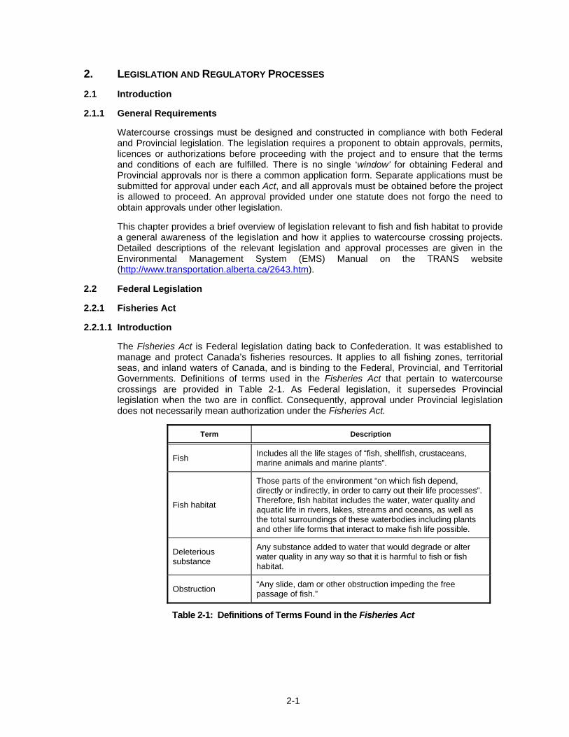
The Fisheries Act is Federal legislation dating back to Confederation. It was established to manage and protect Canada’s fisheries resources. It applies to all fishing zones, territorial seas, and inland waters of Canada, and is binding to the Federal, Provincial, and Territorial Governments. Definitions of terms used in the Fisheries Act that pertain to watercourse crossings are provided in Table 2-1. As Federal legislation, it supersedes Provincial legislation when the two are in conflict. Consequently, approval under Provincial legislation does not necessarily mean authorization under the Fisheries Act.
Term Description
Fish Includes all the life stages of “fish, shellfish, crustaceans, marine animals and marine plants”.
Fish habitat
Those parts of the environment “on which fish depend, directly or indirectly, in order to carry out their life processes”. Therefore, fish habitat includes the water, water quality and aquatic life in rivers, lakes, streams and oceans, as well as the total surroundings of these waterbodies including plants and other life forms that interact to make fish life possible.
Deleterious substance
Any substance added to water that would degrade or alter water quality in any way so that it is harmful to fish or fish habitat.
Obstruction “Any slide, dam or other obstruction impeding the free passage of fish.”
Table 2-1: Definitions of Terms Found in the Fisheries Act
2-2
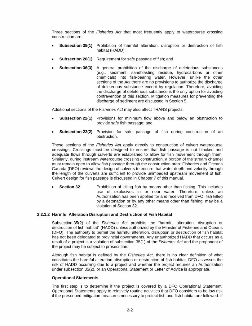
Three sections of the Fisheries Act that most frequently apply to watercourse crossing construction are:
• Subsection 35(1) Prohibition of harmful alteration, disruption or destruction of fish habitat (HADD);
• Subsection 20(1) Requirement for safe passage of fish; and
• Subsection 36(3) A general prohibition of the discharge of deleterious substances (e.g., sediment, sandblasting residue, hydrocarbons or other chemicals) into fish-bearing water. However, unlike the other sections of the Act there are no provisions to authorize the discharge of deleterious substance except by regulation. Therefore, avoiding the discharge of deleterious substance is the only option for avoiding contravention of this section. Mitigation measures for preventing the discharge of sediment are discussed in Section 5.
Additional sections of the Fisheries Act may also affect TRANS projects:
• Subsection 22(1) Provisions for minimum flow above and below an obstruction to provide safe fish passage; and
• Subsection 22(2) Provision for safe passage of fish during construction of an obstruction.
These sections of the Fisheries Act apply directly to construction of culvert watercourse crossings. Crossings must be designed to ensure that fish passage is not blocked and adequate flows through culverts are established to allow for fish movement through them. Similarly, during instream watercourse crossing construction, a portion of the stream channel must remain open to allow fish passage through the construction area. Fisheries and Oceans Canada (DFO) reviews the design of culverts to ensure that water depth and velocity through the length of the culverts are sufficient to provide unimpeded upstream movement of fish. Culvert design for fish passage is discussed in Chapter 7 of this manual.
• Section 32 Prohibition of killing fish by means other than fishing. This includes use of explosives in or near water. Therefore, unless an Authorization has been applied for and received from DFO, fish killed by a detonation or by any other means other than fishing, may be a violation of Section 32.
2.2.1.2 Harmful Alteration Disruption and Destruction of Fish Habitat
Subsection 35(2) of the Fisheries Act prohibits the “harmful alteration, disruption or destruction of fish habitat” (HADD) unless authorized by the Minister of Fisheries and Oceans (DFO). The authority to permit the harmful alteration, disruption or destruction of fish habitat has not been delegated to provincial governments. Any unauthorized HADD that occurs as a result of a project is a violation of subsection 35(1) of the Fisheries Act and the proponent of the project may be subject to prosecution.
Although fish habitat is defined by the Fisheries Act, there is no clear definition of what constitutes the harmful alteration, disruption or destruction of fish habitat. DFO assesses the risk of HADD occurring due to a project and whether the project requires an Authorization under subsection 35(2), or an Operational Statement or Letter of Advice is appropriate.
Operational Statements
The first step is to determine if the project is covered by a DFO Operational Statement. Operational Statements apply to relatively routine activities that DFO considers to be low risk if the prescribed mitigation measures necessary to protect fish and fish habitat are followed. If
2-3
the protection measures are followed by the project proponent, an Authorization or Letter of Advice is not necessary, although DFO does require notification that the project is proceeding. Operational Statements that may be relevant to TRANS projects include:
• Maintenance of Riparian Vegetation in Existing Rights-of-Way
• Culvert Maintenance
• Clear Span Bridges
• Bridge Maintenance
• Beaver Dam Removal
• Isolated or Dry Open-cut Stream Crossings
• Temporary Stream Crossing
• Ice Bridges and Snow Fills
The Alberta Operational Statements are available on the DFO web site: http://www.dfo-mpo.gc.ca/regions/central/habitat/os-eo/provinces-territories-territoires/index-eng.htm
Reviews and Authorizations
If the proposed project is not covered by an Operational Statement, then a project review by DFO should be requested. If there is no fish habitat present, then DFO will have no concerns. However, it may not be readily evident to the proponent if fish habitat is present as defined by DFO (Chapter 4 provides guidance regarding fish and fish habitat inventory procedures.)
An information package should be submitted to DFO for review along with an application for a possible Authorization under the federal Fisheries Act. The request for review application can be found at: http://www.dfo-mpo.gc.ca/oceans-habitat/habitat/water-eau/requirements-exigences/form-formulaire_e.asp?template=print
TRANS has developed a template letter to accompany the DFO application form to help proponents identify and standardize the types of information required for submission to DFO. The template letter can be found on the TRANS website.
Typically the application would be prepared by an environmental consultant on behalf of TRANS, and reviewed and signed by the Project Sponsor from TRANS.
DFO reviews the information for completeness, and determines if fish habitat is present.
If DFO determines that fish habitat is present, then DFO categorizes risk on the basis of the scale of the negative effects and the sensitivity of the fish and fish habitat to change. A project with a low risk of HADD normally results in the issuance of a Letter of Advice; undertakings with a medium or high risk of HADD usually require an Authorization.
2.2.1.3 Authorization Process
Once the information has been reviewed by DFO, a determination will be made as to whether fish habitat will be affected by the project. To summarize, there are four possible outcomes:
1. There is no fish habitat. DFO indicates that they have no concerns and no further need for involvement with the project.
2-4
2. There is fish habitat, but any harmful alteration, disruption or destruction (HADD) of fish habitat can be avoided through implementation of the proposed mitigation measures. A Letter of Advice may be issued instead of an authorization.
3. There is fish habitat, a HADD cannot be avoided through mitigation measures, but DFO determines that the HADD is acceptable and may issue an authorization. Habitat compensation is usually required under these circumstances.
4. There is fish habitat, a HADD cannot be avoided through mitigation measures, and DFO determines that the HADD is unacceptable. No authorization is granted. The proponent may consider redesigning or relocating the project in consultation with DFO and re-submitting the application for an Authorization.
If an Authorization is granted, the proponent must submit a Compensation Plan for the loss of fish habitat (please see Chapter 6, Compensation Procedures). As well, before DFO can issue an authorization, an Environmental Assessment must be undertaken by DFO in accordance with the Canadian Environmental Assessment Act. Additional information may be requested by DFO to facilitate their environmental assessment of the project.
The Authorization usually contains conditions which require the proponent to undertake specific mitigation, compensation and monitoring measures. The Authorization is not an approval of the project itself; rather it is the granting of permission for the HADD resulting from the project.
A process flowchart and checklist for the Fisheries Act are provided in Appendices 3 and 4 respectively of the TRANS EMS manual.
2.2.2 Navigable Waters Protection Act
2.2.2.1 Introduction
The Navigable Waters Protection Act (NWPA) is the Federal legislation that protects the public right of navigation in all navigable waterways and coastal areas across Canada. Navigable waters are defined by the NWPA as “… any body of water capable of being navigated by floating vessels of any description for the purpose of transportation, commerce or recreation.” The NWPA is administered by the Navigable Waters Protection Program (NWPP) of Transport Canada.
The NWPA prohibits the building or placing of any work in, on, over, under, through or across any navigable water unless:
• the work, the site and the plans have been approved by NWPP before work begins; and
• the work is built and maintained according to those plans.
Any works that, in the opinion of the NWPP, do not interfere substantially with navigation may be exempt from requiring approval by subsection 5(2). Additional sections of the NWPA that make provisions for approving existing structures and making repairs and alterations to previously approved structures are:
• Subsection 6(4) approval of existing structures not previously approved or approval of structures currently under construction;
• Subsection 10(1) approval to rebuild or repair approved structures;
• Subsection 10(2) approval of alterations to approved structures; and
• Subsection 11(1) renewal of expired approval.
2-5
The NWPP determines which sections of the NWPA apply to a given project and advises the proponent accordingly.
2.2.2.2 Approval Process
Decision on Navigability
A waterway must be declared navigable for the NWPA to apply. Normally the NWPP does not consider ephemeral streams to be navigable. Streams that cannot be navigated by canoe or kayak, are also generally viewed by NWPP to be non-navigable. If the navigability status of a waterbody is unclear, confirmation should be obtained from the NWPP before proceeding.
If the NWPP confirms that the water is navigable, the NWPA applies and an application for approval of the work(s) should be submitted to NWPP.
Types of Approvals
Applications for NWPA approvals are processed by the NWPP as either Determinations or Approvals.
a) NWPA Subsection 5(2) Determinations
Applications submitted to the NWPP are assessed to determine the effects of the project on navigation. If the Navigable Waters Protection Officer determines that the project will not substantially interfere with navigation, a subsection 5(2) determination, confirming the NWPP has reviewed the plans and indicating that the project complies with the exemption provisions of subsection 5(2) of the NWPA, is issued. Determinations do not require a CEAA review.
b) NWPA Subsection 5(1) Approvals
Projects that have the potential to substantially interfere with navigation require approval under the NWPA. The specific Sections of the NWPA under which approvals are issued are determined by the NWPP.
Approvals generally take longer to process than Determinations. This is because of the additional requirements to advertise the project in local newspapers and the Canada Gazette and complete a CEAA review.
2.2.3 Canadian Environmental Assessment Act
The Canadian Environmental Assessment Act (CEAA) is the legal basis for the Federal nvironental assessment process. The Act defines the responsibilities and procedures for environmental assessments of projects that involve the Federal Government. CEAA comes into effect whenever a project involves federal money, federal lands or when a federal government agency makes a regulatory decision in relation to the project. Most often, CEAA applies when an Authorization under the Fisheries Act or an Approval under the NWPA are issued from the Federal Government.
Once CEAA is triggered, the Federal Authority (government department or agency exercising a power, duty or function) becomes responsible for ensuring that the environmental assessment is conducted according to CEAA procedures. The Federal Authority is then referred to as a Responsible Authority (RA). There can be more than one RA for a given project. DFO is the RA for the Fisheries Act and Transport Canada is the RA for the NWPA.
The TRANS Environmental Management System (EMS) Manual provides a detailed description of the CEAA legislation and approval process.
2-6
2.2.4 Species At Risk Act
The Species at Risk Act (SARA) is intended to prevent indigenous species, subspecies and distinct populations from becoming extirpated or extinct and to provide for the recovery of endangered or threatened species. Fisheries and Oceans Canada (DFO) is designated a ‘competent’ minister under the SARA, responsible for aquatic species. In practice, DFO acts for the minister.
The SARA prohibits the killing, harming or capture of an individual of a species listed under Schedule 1 of the Act as extirpated, endangered or threatened, however a permit for capture may be issued for scientific or research purposes. The SARA also prohibits the damage or destruction of the residence of one or more species that are listed as endangered or threatened or are listed as extirpated species, if a recovery strategy for the re-introduction of the extirpated species has been recommended. DFO can issue an Authorization for the HADD of the habitat of an endangered, threatened or extirpated species; however DFO always designates such species and their habitat as rare, with significant effects. Rather than issuing an Authorization, DFO would likely require that the project be relocated, redesigned or abandoned.
Additional species are periodically added to Schedule 1. The Species at Risk Public Registry should be consulted for confirmation of listed Schedule 1 species. At the current time, two fish species occurring in Alberta, the Western silvery minnow and the Eastslope sculpin, have been listed under Schedule 1 of the SARA, both being designated as threatened. The Western silvery minnow occurs only in the Milk River drainage and the Eastslope sculpin occurs in the St. Mary River and Milk River drainages.
The TRANS EMS Manual provides more information on the SARA.
2.3 Alberta Legislation
2.3.1 Alberta Water Act
The Alberta Water Act represents the water management legislation in Alberta. This section contains basic information about the Water Act as it applies to watercourse crossing projects. Additional information is contained in the TRANS EMS Manual, including a process flow chart and a checklist.
Under the Water Act, an application must be made to conduct any activity in the vicinity of water in Alberta. “Activity” refers to work or action that may result in siltation or a disturbance to flow conditions or the aquatic environment in a waterbody. The detailed definition of “activity” is in subsection 1(1) (b) of the Water Act. Activities include, but are not limited to:
• stream crossings;
• culvert crossings;
• bridge crossings; and
• diversion berm construction.
An activity can range from a temporary diversion to the installation of a permanent structure. Approval is required under the Water Act for any activity unless it is exempt under the Act or regulated under a specific Code of Practice (CoP).
The Water Act legislation includes the Act itself, regulations made under the Act, and various codes of practice, including the CoP for Watercourse Crossings (with management area maps).
Compliance with the Water Act requires a licence, an approval, or strict compliance with the applicable CoP.
2-7
Licences are required for water diversion and to operate water management works (e.g. dam or canal). Approvals will be required for those activities not regulated by the CoP and those that are not exempted. Constructing creek cutoffs or channel realignments beyond 20 meters upstream or downstream of the crossing are examples of projects requiring approval under the Water Act.
2.3.1.1 Code of Practice for Watercourse Crossings
The Watercourse Crossings CoP will address most requirements for TRANS projects. Watercourse crossing types; requirements for plans, monitoring and notification; and the definition of and requirements for a QAES are given in the Code of Practice for Watercourse Crossings available at the Alberta Environment website. Watercourse classifications and applicable timing restrictions are given on Management Area maps that are viewable at the same web site.
The CoP dictates that in planning and implementing an activity, a Qualified Aquatic Environment Specialist (QAES) must carry out specified duties, for example, fish species and habitat site assessments, fish passage requirements, and the determination of appropriate mitigation and compensation measures.
The general process for compliance with the watercourse crossings CoP is as follows:
• establish the crossing type;
• determine watercourse classification and timing restrictions;
• determine if a QAES is required; and
• prepare a plan.
Crossing Type
Four types of permanent watercourse crossings are recognized under the CoP.
Type 1 crossing A watercourse crossing that is constructed using a single span bridge, single span pipeline bridge or similar structure that does not have abutments that are placed on or within the bed or within the active channel of a waterbody1.
Type 2 crossing A watercourse crossing that is constructed using a open bottom culvert, or a single or multi-span bridge with abutments or piers or other similar structures that are placed on or within the bed or within the active channel of a waterbody.
Type 3 crossing A watercourse crossing that is constructed using a round arch or box culvert or other similar structure, on or within the bed of a waterbody.
Type 4 crossing A watercourse crossing that is a ford or low level crossing, or other similar crossing, where the crossing is constructed at or below the level of the bed of the waterbody.
Type 5 crossing A temporary crossing that is constructed using a logfill.
A temporary crossing is required to be removed within six months unless a request is made to the director to extend the six month duration.
1 “Waterbody” means, for the purpose of the CoP, a waterbody with defined bed and banks, whether or not water is continuously present, but does not include fish bearing lakes
2-8
Watercourse Classification and Timing Restrictions
The class of a waterbody is based on the sensitivity of fish habitats and their known distribution. The sensitivity for the class of waterbody is as follows:
Class A Highest sensitivity; habitat areas are sensitive enough to be damaged by any type of activity within the waterbody; known habitats in waterbody critical to the continued viability of a population of fish species in the area.
Class B High sensitivity; habitat areas are sensitive enough to be potentially damaged by any type of activity within the waterbody; habitat areas important to continued viability of a population of fish species in the area.
Class C Moderate sensitivity; habitat areas are sensitive enough to be potentially damaged by unconfined or unrestricted activities within the waterbody; broadly distributed habitats supporting local fish species populations.
Class D Low sensitivity; fish2 species as defined under the CoP are not present.
Restricted activity periods are times when works that disrupt the bed or banks of a waterbody must be avoided to prevent disturbing fish or fish eggs during sensitive periods of their reproductive life cycle (i.e., spawning, egg incubation, fry emergence). The maps identify restricted activity periods for mapped Class B and C water bodies. A qualified aquatic environment specialist (QAES) determines the restricted activity period for a Class A waterbody. Restricted activity periods do not exist for Class D water bodies. The CoP identifies how restricted activity periods for unmapped water bodies may be determined. If the construction of a watercourse crossing is completed within a restricted activity period, the recommendations and instructions of a QAES are required unless otherwise specified under the CoP.
Plans
The owner of a watercourse crossing is required to prepare a plan for the proposed work. This plan is to be prepared a minimum of 14 days prior to commencing the works. In addition, an owner is required to provide notice to the Director, in writing, at least 14 calendar days before any works are carried out. Schedule 3 of the CoP outlines the requirements of the notice to the Director. A copy of the notice is available at Alberta Environment’s website.
A plan for a crossing will consist of the following (refer to the CoP for further details on the requirements for plans):
1) an indication as to the type of crossing and conditions to be used including the specifications and recommendations of a QAES;
2) where required, the specifications of a professional engineer or engineering technician that are prepared in accordance with Parts 1 and 2 of Schedule 2;
3) contingency measures to deal with potential problems; and
4) monitoring plans.
Overall, the plans must be prepared to meet the design and construction standards outlined in Part 1 of Schedule 2, and meet the requirements for the class of waterbody in which the works will take place. Upon completion of the watercourse crossing, the owner of the crossing must confirm the crossing was completed according to the plans prepared for the crossing. The owner retains this information in their records.
2 “Fish” means fish used for domestic, sport and commercial purposes, and fish of special concern, including but not limited to rare, endangered, threatened or vulnerable species
2-9
Monitoring under the CoP includes, but is not limited to:
1) monitoring during construction to assess the immediate effects of the works on the aquatic environment (if required); and
2) post-construction monitoring to assess the condition of the crossing structure and site and effectiveness of mitigation and habitat compensation measures and other measures carried out in association with crossing construction.
It is important to note that compliance with the CoP in this legislation is considered mandatory. Significant consequences may arise from the violation of a CoP.
2.3.1.2 Approvals
The approval process for activities that continue to be regulated under the Water Act, and are not regulated by the CoP, will involve filing an application and other supporting documentation with Alberta Environment. An application for approval is required for activities such as cutoffs, channel realignment and drainage. Minor channel realignments associated with a culvert or bridge installation (less than 20 metres upstream and downstream of the crossing) can be undertaken as an activity under the CoP. As a general guideline, an application for an approval is needed when activity is undertaken in a waterbody with defined bed and banks. A copy of the application form is available at the Alberta Environment website. The application form lists the Regional contacts.
2.3.2 Alberta Environmental Protection and Enhancement Act
The Environmental Protection and Enhancement Act (EPEA) is the legal basis for the Alberta environmental assessment process. The EPEA defines the responsibilities and procedures for environmental assessments of projects within the province of Alberta. In general the EPEA applies to activities taking place on the approach to a watercourse, the crossing itself is governed under the Codes of Practice for Watercourse Crossings.
Additional information on the EPEA is given in the TRANS EMS Manual, including a process flow chart and checklist.
2.3.3 Alberta Public Lands Act
The Alberta Public Lands Act is the Provincial legislation that administers public lands (lands owned by Her Majesty the Queen in the right of Alberta). The beds and shores of all lakes, rivers, streams, watercourses and waterbodies are considered public lands unless they are owned by the Government of Canada or their ownership is expressly stated on the land title registered prior to June 18, 1931 (Section 3, Public Lands Act).
The Public Lands Act administers only those lands that are pursuant to the Act. Other Provincial Crown lands are administered through legislation such as the:
• Provincial Parks Act
• Wilderness Areas, Ecological reserves and Natural Areas Act
• Willmore Wilderness Park Act
In addition, Alberta Municipal Affairs also manages certain aspects of Provincial Crown land.
2-10
Under the Public Lands Act, approvals are required for any activity, on the Crown owned bed or shore of a river, stream or lake prior to development that may include but are not limited to:
• any project (temporary or permanent) involving the occupation of the bed or shore of a river, stream or lake;
• the realignment of a natural watercourse;
• any projects that involve the placement onto or the removal of material from the bed or shore of a waterbody;
• erosion protection, retaining walls, groynes, breakwaters and causeways;
• permanent waterline installations into, or beneath, the river, stream or lake; and
• other permanent structures on the bed or shore of a river, stream or lake.
Anyone wishing to use, alter or occupy the bed and shore of a waterbody must first ensure that they have legal access to it, and secondly, obtain written approval from the appropriate provincial government agency if the Crown-owned bed and shore of a waterbody is to be disturbed or modified. Authority to use public land is granted through a disposition license of occupation (LOC) approval or other authorization issued under the provisions of the Alberta Public Lands Act.
The Public Lands Act defers to the Codes of Practice for Watercourse Crossings during construction and post-construction activities associated with watercourse crossings.
Work that affects the beds of waterbodies or the adjacent public shore lands may require an approval or disposition issued pursuant to the Alberta Public Lands Act. Applications for Public Lands Act approvals or dispositions can be submitted to the local SRD Land Division Office, or electronically, using the Land Division’s electronic disposition system (EDS).
The TRANS EMS Manual has additional information on the Public Lands Act, including a process flow chart and check list.
2.4 Aboriginal Consultation
TRANS, as a Ministry of the Alberta provincial Crown, has a legal duty to uphold the “honour of the Crown,” when consulting with First Nations, as required by section 35 of the Constitution Act, 1982, and the Supreme Court of Canada (SCC). To uphold the honour of the Crown, TRANS must consult with First Nations when decisions by the department have the potential to adversely impact Rights and Traditional Uses. Failure to uphold the honour of the Crown could result in legal actions against TRANS, judicial reviews of TRANS’ decisions, delay in project plans, and potential harm to TRANS’ relationships with First Nations.
The scope and level of consultation will be determined by the degree of potential adverse effects the proposed project may have on First Nations Rights and Traditional Uses.
TRANS must begin consultation as soon as TRANS knows, or has reasons to suspect, that its decision has the potential to impact a First Nation’s Rights and Traditional Uses. The duty to consult applies mostly to Crown land, but could in some limited situations also arise for projects on private land, if the Crown is making a decision in relation to that project. Consultation will apply to freehold private lands purchased by the department where evidence of historical or current traditional uses is identified.
The SCC has determined that the Crown not only has a legal duty to consult, but must do so in a meaningful manner. Until this notion is further defined by the courts, consultation should be conducted with the intent to substantially address First Nations concerns in a reasonable
2-11
manner. It is recommended that consultation be conducted at the strategic planning stage or earlier in order to ensure that potential adverse impacts are dealt with as expeditiously as possible.
Government of Alberta policy and guidelines regarding First Nations consultation can be found on the Alberta Relations website. Department-specific consultation guidelines and procedures are under development.
1 “Rights and Traditional Uses” include uses of public lands such as burial grounds, gathering sites, and historic and ceremonial locations, and existing constitutionally protected rights to hunt, trap and fish, and does not refer to proprietary interests in land.

2-12
Page left blank intentionally
CHAPTER 3
3-i
TABLE OF CONTENTS 3. FISH HABITAT AND POTENTIAL IMPACTS ........................................................3-1
3.1 Fish Habitat Requirements ............................................................................3-1
3.1.1 Food...........................................................................................................3-1
3.1.2 Cover .........................................................................................................3-4
3.1.3 Reproduction ............................................................................................3-4
3.1.4 Migration ...................................................................................................3-4
3.1.5 Water Quality ............................................................................................3-4
3.2 Impacts of Watercourse Crossing Construction
and Maintenance Activities............................................................................3-4
3.2.1 Sediment Impacts.....................................................................................3-5
3.2.2 Changes to Channel Morphology ...........................................................3-6
3.2.3 Alteration and Removal of Fish Habitat, including Riparian Vegetation3-7
3.2.4 Flow Disruption or Blockage of Fish Passage ......................................3-7
3.2.5 Deleterious Substances...........................................................................3-8
LIST OF TABLES Table 3-1 Common and Scientific Names, Conservation Status and Life History
Information Sources for Alberta Fish ....................................................3-2
LIST OF FIGURES Figure 3-1 Basic Habitat Requirements for Fish.....................................................3-1
Figure 3-2 Potential Effects of Sediment on Fish and Fish Habitat ......................3-6

3-ii
Page left blank intentionally
3-1
3. FISH HABITAT AND POTENTIAL IMPACTS
3.1 Fish Habitat Requirements
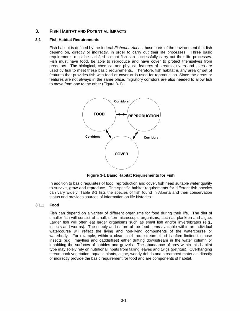
Fish habitat is defined by the federal Fisheries Act as those parts of the environment that fish depend on, directly or indirectly, in order to carry out their life processes. Three basic requirements must be satisfied so that fish can successfully carry out their life processes. Fish must have food, be able to reproduce and have cover to protect themselves from predators. The biological, chemical and physical features of streams, rivers and lakes are used by fish to meet these basic requirements. Therefore, fish habitat is any area or set of features that provides fish with food or cover or is used for reproduction. Since the areas or features are not always in the same place, migratory corridors are also needed to allow fish to move from one to the other (Figure 3-1).
FOOD REPRODUCTION
COVER
Corridors
CorridorsCorridors
Figure 3-1 Basic Habitat Requirements for Fish
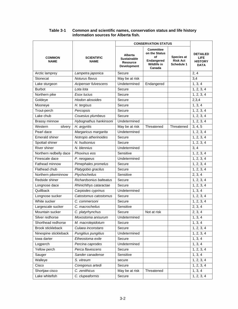
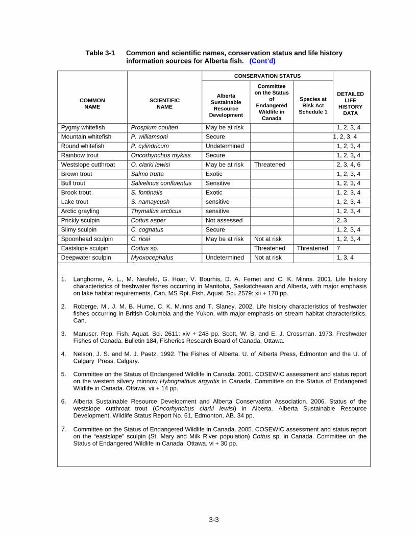
In addition to basic requisites of food, reproduction and cover, fish need suitable water quality to survive, grow and reproduce. The specific habitat requirements for different fish species can vary widely. Table 3-1 lists the species of fish found in Alberta and their conservation status and provides sources of information on life histories.
3.1.1 Food
Fish can depend on a variety of different organisms for food during their life. The diet of smaller fish will consist of small, often microscopic organisms, such as plankton and algae. Larger fish will often eat larger organisms such as small fish and/or invertebrates (e.g., insects and worms). The supply and nature of the food items available within an individual watercourse will reflect the living and non-living components of the watercourse or waterbody. For example, within a clear, cold trout stream, food is often limited to those insects (e.g., mayflies and caddisflies) either drifting downstream in the water column or inhabiting the surfaces of cobbles and gravels. The abundance of prey within this habitat type may solely rely on nutritional inputs from falling leaves and twigs (detritus). Overhanging streambank vegetation, aquatic plants, algae, woody debris and streambed materials directly or indirectly provide the basic requirement for food and are components of habitat.
3-2
Table 3-1 Common and scientific names, conservation status and life history information sources for Alberta fish.
CONSERVATION STATUS
COMMON NAME
SCIENTIFIC NAME
Alberta
Sustainable Resource
Development
Committee on the Status
of Endangered Wildlife in
Canada
Species at Risk Act
Schedule 1
DETAILED LIFE
HISTORY DATA
Arctic lamprey Lampetra japonica Secure 2, 4 Stonecat Noturus flavus May be at risk 3,4 Lake sturgeon Acipenser fulvescens Undetermined Endangered 1, 3, 4 Burbot Lota lota Secure 1, 2, 3, 4 Northern pike Esox lucius Secure 1, 2, 3, 4 Goldeye Hiodon alosoides Secure 2,3,4 Mooneye H. tergisus Secure 1, 3, 4 Trout-perch Percopsis
iSecure 1, 2, 3, 4
Lake chub Couesius plumbeus Secure 1, 2, 3, 4 Brassy minnow Hybognathus hankinsoni Undetermined 1, 2, 3, 4 Western silvery
iH. argyritis May be at risk Threatened Threatened 3, 4, 5
Pearl dace Margaricus margarita Undetermined 1, 2, 3, 4 Emerald shiner Notropis atherinoides Secure 1, 2, 3, 4 Spottail shiner N. hudsonius Secure 1, 2, 3, 4 River shiner N. blennius Undetermined 3, 4 Northern redbelly dace Phoxinus eos Sensitive 1, 2, 3, 4 Finescale dace P. neogaeus Undetermined 1, 2, 3, 4 Fathead minnow Pimephales promelus Secure 1, 2, 3, 4 Flathead chub Platygobio gracilus Secure 1, 2, 3, 4 Northern pikeminnow Ptychocheilus Sensitive 2, 3, 4 Redside shiner Richardsonius balteatus Secure 1, 2, 3, 4 Longnose dace Rhinichthys cataractae Secure 1, 2, 3, 4 Quillback Carpiodes cyprinus Undetermined 1, 3, 4 Longnose sucker Catostomus catostomus Secure 1, 2, 3, 4 White sucker C. commersoni Secure 1, 2, 3, 4 Largescale sucker C. macrocheilus Sensitive 2, 3, 4 Mountain sucker C. platyrhynchus Secure Not at risk 2, 3, 4 Silver redhorse Moxostoma anisurum Undetermined 1, 3, 4 Shorthead redhorse M. macrolepidotum Secure 1, 3, 4 Brook stickleback Culaea inconstans Secure 1, 2, 3, 4 Ninespine stickleback Pungitius pungitius Undetermined 1, 2, 3, 4 Iowa darter Etheostoma exile Secure 1, 3, 4 Logperch Percina caprodes Undetermined 1, 3, 4 Yellow perch Perca flavescens Secure 1, 2, 3, 4 Sauger Sander canadense Sensitive 1, 3, 4 Walleye S. vitreum secure 1, 2, 3, 4 Cisco Coregonus artedi Secure 1, 2, 3, 4 Shortjaw cisco C. zenithicus May be at risk Threatened 1, 3, 4 Lake whitefish C. clupeaformis Secure 1, 2, 3, 4
3-3
Table 3-1 Common and scientific names, conservation status and life history information sources for Alberta fish. (Cont’d)
CONSERVATION STATUS
COMMON NAME
SCIENTIFIC NAME
Alberta
Sustainable Resource
Development
Committee on the Status
of Endangered Wildlife in
Canada
Species at Risk Act
Schedule 1
DETAILED LIFE
HISTORY DATA
Pygmy whitefish Prospium coulteri May be at risk 1, 2, 3, 4 Mountain whitefish P. williamsoni Secure 1, 2, 3, 4 Round whitefish P. cylindricum Undetermined 1, 2, 3, 4 Rainbow trout Oncorhynchus mykiss Secure 1, 2, 3, 4 Westslope cutthroat t t
O. clarki lewisi May be at risk Threatened 2, 3, 4, 6 Brown trout Salmo trutta Exotic 1, 2, 3, 4 Bull trout Salvelinus confluentus Sensitive 1, 2, 3, 4 Brook trout S. fontinalis Exotic 1, 2, 3, 4 Lake trout S. namaycush sensitive 1, 2, 3, 4 Arctic grayling Thymallus arcticus sensitive 1, 2, 3, 4 Prickly sculpin Cottus asper Not assessed 2, 3 Slimy sculpin C. cognatus Secure 1, 2, 3, 4 Spoonhead sculpin C. ricei May be at risk Not at risk 1, 2, 3, 4 Eastslope sculpin Cottus sp. Threatened Threatened 7 Deepwater sculpin Myoxocephalus
th iUndetermined Not at risk 1, 3, 4
1. Langhorne, A. L., M. Neufeld, G. Hoar, V. Bourhis, D. A. Fernet and C. K. Minns. 2001. Life history characteristics of freshwater fishes occurring in Manitoba, Saskatchewan and Alberta, with major emphasis on lake habitat requirements. Can. MS Rpt. Fish. Aquat. Sci. 2579: xii + 170 pp.
2. Roberge, M., J. M. B. Hume, C. K. M.inns and T. Slaney. 2002. Life history characteristics of freshwater fishes occurring in British Columbia and the Yukon, with major emphasis on stream habitat characteristics. Can.
3. Manuscr. Rep. Fish. Aquat. Sci. 2611: xiv + 248 pp. Scott, W. B. and E. J. Crossman. 1973. Freshwater Fishes of Canada. Bulletin 184, Fisheries Research Board of Canada, Ottawa.
4. Nelson, J. S. and M. J. Paetz. 1992. The Fishes of Alberta. U. of Alberta Press, Edmonton and the U. of Calgary Press, Calgary.
5. Committee on the Status of Endangered Wildlife in Canada. 2001. COSEWIC assessment and status report on the western silvery minnow Hybognathus argyritis in Canada. Committee on the Status of Endangered Wildlife in Canada. Ottawa. vii + 14 pp.
6. Alberta Sustainable Resource Development and Alberta Conservation Association. 2006. Status of the westslope cutthroat trout (Oncorhynchus clarki lewisi) in Alberta. Alberta Sustainable Resource Development, Wildlife Status Report No. 61, Edmonton, AB. 34 pp.
7. Committee on the Status of Endangered Wildlife in Canada. 2005. COSEWIC assessment and status report on the “eastslope” sculpin (St. Mary and Milk River population) Cottus sp. in Canada. Committee on the Status of Endangered Wildlife in Canada. Ottawa. vi + 30 pp.
3-4
3.1.2 Cover
Cover provides individual fish with areas of refuge from predators, competitors and periods of high flow. Rocks, woody debris, undercut banks, overhanging vegetation, aquatic vegetation and deep water can all provide cover. Young or small fish are especially dependent on areas with cover to feed, and to avoid predators or physical displacement downstream.
3.1.3 Reproduction
Requirements for reproduction vary widely between species but most fish need specific substrate, water temperature and water velocity conditions for successful spawning. Coldwater species such as rainbow trout prefer gravel bottomed riffle areas in streams, with cold water temperatures and moderate water velocities (0.3 to 0.9 m/s) while northern pike (a coolwater species) utilize wetland areas, or vegetated floodplains of rivers, marshes and bays to spawn.
3.1.4 Migration
Migration corridors for fish movement between the three habitat components (food, cover and reproduction) are also included within the definition of fish habitat. Migration areas consist of stream or river reaches that provide corridors for fish movement from one area of the watershed to another. Migration barriers such as beaver dams, perched culverts and low water flows can prevent fish from reaching or leaving spawning and overwintering habitats. High flow velocities at inlets, outlets and within culverts can also prevent fish migrations.
3.1.5 Water Quality
Fish require good water quality in which to live, grow, reproduce and feed. Water quality parameters that vary outside of acceptable levels can affect fish directly through behavioural and physiological changes or indirectly by affecting food supply or habitat. Rapid or extreme water quality changes may result in physiological trauma (e.g., organ damage) or death. Water quality parameters that can affect fish include water temperature, dissolved oxygen, pH, turbidity, ammonia, salinity, dissolved metal concentrations and other toxic substances such as chlorinated organics, oils, pesticides, etc.
3.2 Impacts of Watercourse Crossing Construction and Maintenance Activities
The construction of bridge and culvert watercourse crossings has the potential to negatively affect fish and fish habitat. This can result from activities associated with the construction of the crossing structures or from the subsequent influence of completed structures on fish habitat. The following section outlines the potential impacts on fish and fish habitat as a result of:
• increased sediment loading (e.g., suspended or depositional sediment);
• changes in channel morphology;
• alteration and removal fish habitat, including streambank and riparian vegetation;
• flow disruption or blockage of fish passage; and
• release of deleterious substances into the watercourse.
Gravel extraction from rivers and streams has the potential to impact fish and fish habitat in all of these ways. Both Alberta Environment and Fisheries and Oceans Canada should be contacted if gravel extraction from the floodplain or the waterbody is being considered. Both agencies are concerned about the effects of gravel extraction on the stream channel and habitats and may not approve application for instream or floodplain gravel extraction.
3-5
3.2.1 Sediment Impacts
Previous monitoring studies have shown that the primary change in water quality due to bridges or culverts is elevated levels of suspended sediment. Construction activities cause short-term effects, but subsequent erosion of ditches and slopes may cause more serious long-term effects if not mitigated. Sediment can be released into a watercourse as a result of:
• instream construction activities such as equipment crossings, excavation, blasting, and the installation of erosion control measures (riprap);
• erosion from ditches, steep slopes and exposed areas on the right-of-way;
• increased bed scour or bank erosion due to changes in downstream flow patterns or the sudden release of water when a cofferdam or beaver dam is removed;
• mobilization of accumulated sediment when a cofferdam or beaver dam is removed; and
• headcutting upstream of a streambed alteration.
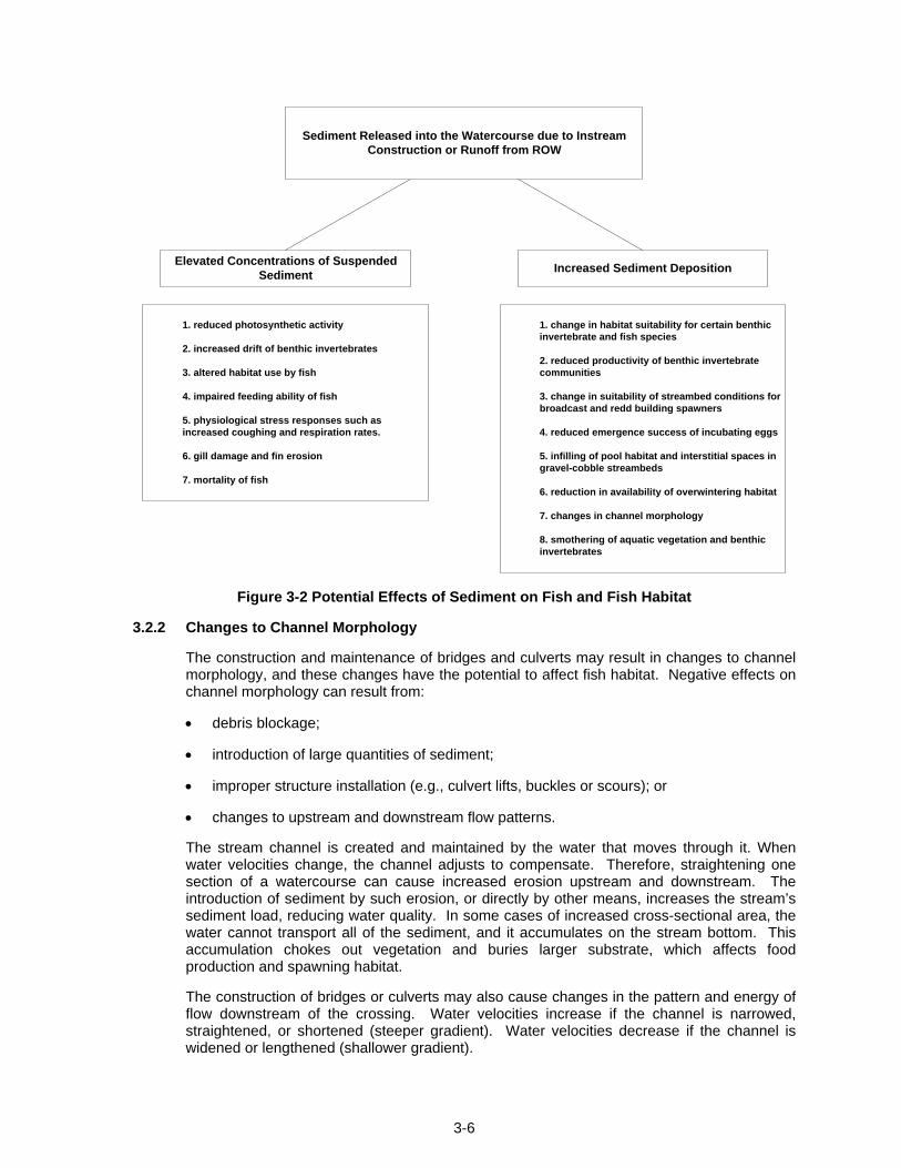
Regardless of how sediment enters the water, the effects are the same. High sediment levels rarely kill adult fish, but can harm eggs and young. When the sediment eventually settles on the stream bottom, it can bury important food, spawning, and cover habitat. Figure 3-2 outlines potential effects of increased sediment loading on fish and fish habitat.
Observed sediment-related effects of bridge and culvert construction include changes to downstream streambed conditions, reductions in periphyton (algae), and in the abundance and diversity of benthic invertebrate and fish communities. Generally, stream conditions and benthic invertebrate populations recover to pre-construction levels within 1-2 years after construction (Barton 1977; Reed 1977).
However, more permanent effects have been reported. For example, highway bridge construction in Ontario caused a shift in fish community structure favouring midwater feeders (e.g., blacknose dace) over bottom feeding fish (sucker and sculpin species) that persisted for six years (Taylor and Roff 1986). King and Ball (1964) observed that interstate highway construction filled or decreased pool depths such that smallmouth bass were eliminated from some reaches of Red Cedar River, Michigan. Bowlby et al. (1987) also documented long-term shifts in streambed conditions and benthic invertebrate community structure downstream of a highway crossing in Ontario.
Long-term sediment-related impacts have also been associated with culverts. Improperly sized culverts are prone to washing out, and displaced embankment fill and bed material can damage downstream habitats by increasing sediment loads and deposition. Watersheds with larger numbers of culverts per unit area have been observed to have higher quantities of fine sediments in streambeds and lower trout biomass (Eaglin and Hubert 1993).
Road and stream crossing maintenance may also introduce sediment into streams. This may occur during snow removal, bridge cleaning, sandblasting or deck replacement, and can also be caused indirectly by any activity that increases soil erosion in ditches or along stream banks. Some routine maintenance activities stir up sediment that is already present on the streambed. This can happen when beaver dams are removed, during culvert replacement or when machinery enters the water. It is essential to perform maintenance activities using best management practices (BMPs) and other measures that minimize the introduction of sediment into streams. Ditches and slopes must be regularly inspected and maintained to ensure that erosion is controlled.
3-6
Sediment Released into the Watercourse due to InstreamConstruction or Runoff from ROW
1. reduced photosynthetic activity
2. increased drift of benthic invertebrates
3. altered habitat use by fish
4. impaired feeding ability of fish
5. physiological stress responses such asincreased coughing and respiration rates.
6. gill damage and fin erosion
7. mortality of fish
1. change in habitat suitability for certain benthicinvertebrate and fish species
2. reduced productivity of benthic invertebratecommunities
3. change in suitability of streambed conditions forbroadcast and redd building spawners
4. reduced emergence success of incubating eggs
5. infilling of pool habitat and interstitial spaces ingravel-cobble streambeds
6. reduction in availability of overwintering habitat
7. changes in channel morphology
8. smothering of aquatic vegetation and benthicinvertebrates
Elevated Concentrations of SuspendedSediment Increased Sediment Deposition
Figure 3-2 Potential Effects of Sediment on Fish and Fish Habitat
3.2.2 Changes to Channel Morphology
The construction and maintenance of bridges and culverts may result in changes to channel morphology, and these changes have the potential to affect fish habitat. Negative effects on channel morphology can result from:
• debris blockage;
• introduction of large quantities of sediment;
• improper structure installation (e.g., culvert lifts, buckles or scours); or
• changes to upstream and downstream flow patterns.
The stream channel is created and maintained by the water that moves through it. When water velocities change, the channel adjusts to compensate. Therefore, straightening one section of a watercourse can cause increased erosion upstream and downstream. The introduction of sediment by such erosion, or directly by other means, increases the stream’s sediment load, reducing water quality. In some cases of increased cross-sectional area, the water cannot transport all of the sediment, and it accumulates on the stream bottom. This accumulation chokes out vegetation and buries larger substrate, which affects food production and spawning habitat.
The construction of bridges or culverts may also cause changes in the pattern and energy of flow downstream of the crossing. Water velocities increase if the channel is narrowed, straightened, or shortened (steeper gradient). Water velocities decrease if the channel is widened or lengthened (shallower gradient).
3-7
Changes in water velocities cause both local and large scale effects. Locally, bed materials can change, with finer particles deposited where the water velocity is reduced, or removed where the velocity is faster. Velocity increases can result in downstream scouring of the streambed or increased erosion of downstream banks. Flow constrictions at culvert inlets can result in headcutting which progresses upstream from the tie-in point with the natural channel. In extreme cases, the entire character of the channel and the habitat it provides is altered or lost. The magnitude of these potential effects will ultimately be reflected in the degree of change in flow patterns and channel morphology. These impacts can be minimized through the application of proper design procedures.
Construction and maintenance activities can change bank and bed materials. Such activities include installing riprap, crushing or compacting substrate or collapsing streambanks. Changes in either bank or substrate material can initiate or exacerbate streambed and bank erosion and change the channel shape or cross-section.
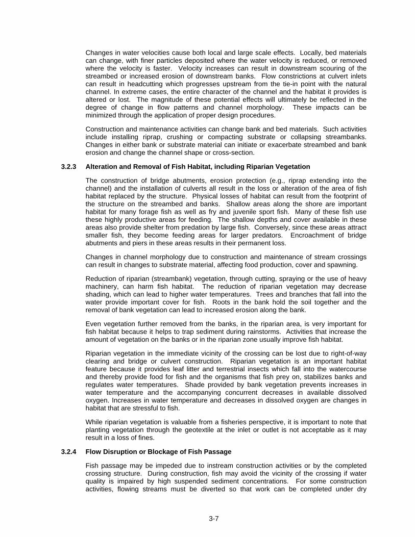
3.2.3 Alteration and Removal of Fish Habitat, including Riparian Vegetation
The construction of bridge abutments, erosion protection (e.g., riprap extending into the channel) and the installation of culverts all result in the loss or alteration of the area of fish habitat replaced by the structure. Physical losses of habitat can result from the footprint of the structure on the streambed and banks. Shallow areas along the shore are important habitat for many forage fish as well as fry and juvenile sport fish. Many of these fish use these highly productive areas for feeding. The shallow depths and cover available in these areas also provide shelter from predation by large fish. Conversely, since these areas attract smaller fish, they become feeding areas for larger predators. Encroachment of bridge abutments and piers in these areas results in their permanent loss.
Changes in channel morphology due to construction and maintenance of stream crossings can result in changes to substrate material, affecting food production, cover and spawning.
Reduction of riparian (streambank) vegetation, through cutting, spraying or the use of heavy machinery, can harm fish habitat. The reduction of riparian vegetation may decrease shading, which can lead to higher water temperatures. Trees and branches that fall into the water provide important cover for fish. Roots in the bank hold the soil together and the removal of bank vegetation can lead to increased erosion along the bank.
Even vegetation further removed from the banks, in the riparian area, is very important for fish habitat because it helps to trap sediment during rainstorms. Activities that increase the amount of vegetation on the banks or in the riparian zone usually improve fish habitat.
Riparian vegetation in the immediate vicinity of the crossing can be lost due to right-of-way clearing and bridge or culvert construction. Riparian vegetation is an important habitat feature because it provides leaf litter and terrestrial insects which fall into the watercourse and thereby provide food for fish and the organisms that fish prey on, stabilizes banks and regulates water temperatures. Shade provided by bank vegetation prevents increases in water temperature and the accompanying concurrent decreases in available dissolved oxygen. Increases in water temperature and decreases in dissolved oxygen are changes in habitat that are stressful to fish.
While riparian vegetation is valuable from a fisheries perspective, it is important to note that planting vegetation through the geotextile at the inlet or outlet is not acceptable as it may result in a loss of fines.
3.2.4 Flow Disruption or Blockage of Fish Passage
Fish passage may be impeded due to instream construction activities or by the completed crossing structure. During construction, fish may avoid the vicinity of the crossing if water quality is impaired by high suspended sediment concentrations. For some construction activities, flowing streams must be diverted so that work can be completed under dry
3-8
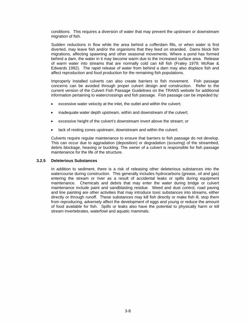
conditions. This requires a diversion of water that may prevent the upstream or downstream migration of fish.
Sudden reductions in flow while the area behind a cofferdam fills, or when water is first diverted, may leave fish and/or the organisms that they feed on stranded. Dams block fish migrations, affecting spawning and other seasonal movements. Where a pond has formed behind a dam, the water in it may become warm due to the increased surface area. Release of warm water into streams that are normally cold can kill fish (Fraley 1979; McRae & Edwards 1992). The rapid release of water from behind a dam may also displace fish and affect reproduction and food production for the remaining fish populations.
Improperly installed culverts can also create barriers to fish movement. Fish passage concerns can be avoided through proper culvert design and construction. Refer to the current version of the Culvert Fish Passage Guidelines on the TRANS website for additional information pertaining to watercrossings and fish passage. Fish passage can be impeded by:
• excessive water velocity at the inlet, the outlet and within the culvert;
• inadequate water depth upstream, within and downstream of the culvert;
• excessive height of the culvert’s downstream invert above the stream; or
• lack of resting zones upstream, downstream and within the culvert.
Culverts require regular maintenance to ensure that barriers to fish passage do not develop. This can occur due to aggradation (deposition) or degradation (scouring) of the streambed, debris blockage, heaving or buckling. The owner of a culvert is responsible for fish passage maintenance for the life of the structure.
3.2.5 Deleterious Substances
In addition to sediment, there is a risk of releasing other deleterious substances into the watercourse during construction. This generally includes hydrocarbons (grease, oil and gas) entering the stream or river as a result of accidental leaks or spills during equipment maintenance. Chemicals and debris that may enter the water during bridge or culvert maintenance include paint and sandblasting residue. Weed and dust control, road paving and line painting are other activities that may introduce toxic substances into streams, either directly or through runoff. These substances may kill fish directly or make fish ill, stop them from reproducing, adversely affect the development of eggs and young or reduce the amount of food available for fish. Spills or leaks also have the potential to physically harm or kill stream invertebrates, waterfowl and aquatic mammals.
CHAPTER 4
4-i
TABLE OF CONTENTS 4. FISH AND FISH HABITAT INVENTORY PROCEDURES................................................ 4-1
4.1 Need for Fish and Fish Habitat Inventories............................................................... 4-1
4.2 Fish Habitat Inventory ................................................................................................. 4-1
4.2.1 Habitat Mapping.................................................................................................... 4-1
4.2.2 Habitat Map Interpretation ................................................................................... 4-6
4.2.3 Habitat Characteristics......................................................................................... 4-6
4.2.4 Watercourse Form and Flow Characteristics .................................................... 4-7
4.3 Fish Community Inventory.......................................................................................... 4-8
4.4 Incorporating Data into Watercourse Crossing Planning, Design and Construction……………………………………............. …………………………………4-12
4.4.1 Functional Planning Study ................................................................................ 4-14
4.4.2 Bridge Assessments and Planning .................................................................. 4-14
4.4.3 Design Phase ...................................................................................................... 4-14
4.4.4 Construction Phase............................................................................................ 4-15
LIST OF TABLES Table 4-1 Large River Habitat Classification System (R.L. & L. 1994) .................................. 4-3
Table 4-2 Small River or Stream Habitat Classification and Rating System Adapted from R.L.& L. 1994 and Hawkins et al. 1993) ........................................... 4-5
Table 4-3 Substrate Criteria (Overton et al. 1997) ................................................................... 4-7
Table 4-4 Overview of Different Active (A) and Passive (P) Fish Capture Methods and Considerations for their Usage................................................................................. 4-9
Table 4-5 TRANS Bridge Planning, Detailed Design and Construction Process for Watercourse Crossing Projects.............................................................................. 4-13

4-ii
Page left blank intentionally
4-1
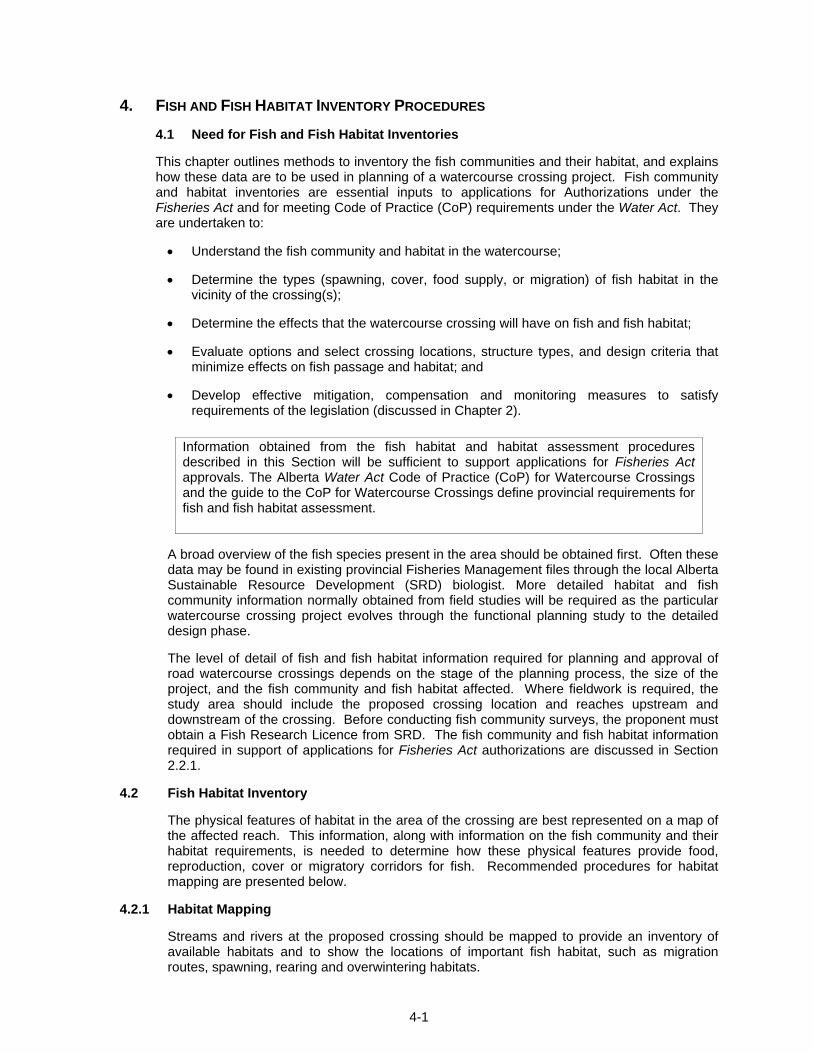
4. FISH AND FISH HABITAT INVENTORY PROCEDURES
4.1 Need for Fish and Fish Habitat Inventories
This chapter outlines methods to inventory the fish communities and their habitat, and explains how these data are to be used in planning of a watercourse crossing project. Fish community and habitat inventories are essential inputs to applications for Authorizations under the Fisheries Act and for meeting Code of Practice (CoP) requirements under the Water Act. They are undertaken to:
• Understand the fish community and habitat in the watercourse;
• Determine the types (spawning, cover, food supply, or migration) of fish habitat in the vicinity of the crossing(s);
• Determine the effects that the watercourse crossing will have on fish and fish habitat;
• Evaluate options and select crossing locations, structure types, and design criteria that minimize effects on fish passage and habitat; and
• Develop effective mitigation, compensation and monitoring measures to satisfy requirements of the legislation (discussed in Chapter 2).
A broad overview of the fish species present in the area should be obtained first. Often these data may be found in existing provincial Fisheries Management files through the local Alberta Sustainable Resource Development (SRD) biologist. More detailed habitat and fish community information normally obtained from field studies will be required as the particular watercourse crossing project evolves through the functional planning study to the detailed design phase.
The level of detail of fish and fish habitat information required for planning and approval of road watercourse crossings depends on the stage of the planning process, the size of the project, and the fish community and fish habitat affected. Where fieldwork is required, the study area should include the proposed crossing location and reaches upstream and downstream of the crossing. Before conducting fish community surveys, the proponent must obtain a Fish Research Licence from SRD. The fish community and fish habitat information required in support of applications for Fisheries Act authorizations are discussed in Section 2.2.1.
4.2 Fish Habitat Inventory
The physical features of habitat in the area of the crossing are best represented on a map of the affected reach. This information, along with information on the fish community and their habitat requirements, is needed to determine how these physical features provide food, reproduction, cover or migratory corridors for fish. Recommended procedures for habitat mapping are presented below.
4.2.1 Habitat Mapping
Streams and rivers at the proposed crossing should be mapped to provide an inventory of available habitats and to show the locations of important fish habitat, such as migration routes, spawning, rearing and overwintering habitats.
Information obtained from the fish habitat and habitat assessment procedures described in this Section will be sufficient to support applications for Fisheries Act approvals. The Alberta Water Act Code of Practice (CoP) for Watercourse Crossings and the guide to the CoP for Watercourse Crossings define provincial requirements for fish and fish habitat assessment.
4-2
A habitat map should be prepared by dividing the channel into a continuous series of habitat types. This should be done on a base map, prepared from topographic maps or air photos, and drawn to scale. In addition to general habitat types, special habitat features (such as trout spawning redds) should be recorded on the map. The incorporation of a habitat classification system is key to the development of a good habitat map. The habitat classification system provides a bridge between physical habitat features and the habitat requirements of the fish species and their life stages. Recommended habitat classification systems for large rivers and smaller streams are outlined in Tables 4-1 and 4-2, respectively.
For the purposes of the habitat classification system, large rivers are defined as those watercourses that do not show any differentiation of channel units (e.g., distinct pool, riffle and run habitats are absent). While differences in depth may occur across the river channel, habitat features are generally associated with shoreline areas, areas of instream islands and the confluence of tributaries. These areas are also the most likely to be affected by watercourse crossing construction. The habitat classification for large rivers therefore focuses on shoreline habitats. Examples of mapped habitat features include the depth of water along the shoreline, protrusions from the bank which create low velocity areas, fallen debris, overhanging vegetation and substrate type.
The habitat classification system for smaller watercourses identifies individual channel units as indicated in Table 4-2. These units are defined as sections of stream of homogeneous depth, velocity and cover. This system is employed to map all watercourses that have distinct channel units such as pool, riffle and run habitats. The area of channel unit types is measured. Dominant channel unit types are assumed to extend the full width of the channel. Wetted channel width, bankfull width and length are measured for each unit. The area of channel unit types can also be scaled from the habitat map.
The channel units and class categories used in the classification system for smaller watercourses relate instream habitat features to their potential use by various fish species and their life stages. For example, riffles (RF) and the transition areas from runs (R1) to riffles (RF) may indicate the presence of suitable spawning areas for trout.
The habitat features of a reach should be mapped according to the habitat classification system. In addition, any special or unique features that might influence the availability or use of habitat should also be recorded. Examples include culverts, beaver dams, pipeline rights-of-way, known spawning redds, piers or abandoned bridge abutments.
The length of habitat mapped upstream and downstream of the crossing depends on the size of the watercourse. There is no rule for calculating the distance upstream or downstream to be surveyed. However, the distance evaluated is greater for larger watercourses than smaller ones. For small creeks or tributaries, assessments are typically limited to 100 m upstream and downstream. For large rivers such as the North Saskatchewan, two to three kilometers of habitat downstream are often evaluated. The study area should generally include one crossover (the point at which the main current of the river goes from one bank across to the other) upstream and one crossover downstream of the study area. In no case should the study area be less than 100 meters on either side of the crossing.
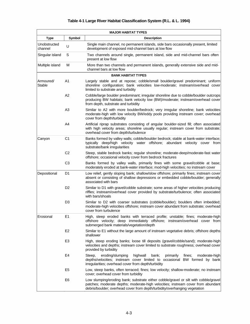
Table 4-1 Large River Habitat Classification System (R.L. & L. 1994)
4-3
MAJOR HABITAT TYPES
Type Symbol Description
Unobstructed channel U Single main channel, no permanent islands, side bars occasionally present, limited
development of exposed mid-channel bars at low flow
Singular island S Two channels around single, permanent island, side and mid-channel bars often present at low flow
Multiple island M More than two channels and permanent islands, generally extensive side and mid-channel bars at low flow
BANK HABITAT TYPES
Armoured/ Stable
A1 Largely stable and at repose; cobble/small boulder/gravel predominant; uniform shoreline configuration; bank velocities low-moderate; instream/overhead cover limited to substrate and turbidity
A2 Cobble/large boulder predominant; irregular shoreline due to cobble/boulder outcrops producing BW habitats; bank velocity low (BW)/moderate; instream/overhead cover from depth, substrate and turbidity
A3 Similar to A2 with more boulder/bedrock; very irregular shoreline; bank velocities moderate-high with low velocity BW/eddy pools providing instream cover; overhead cover from depth/turbidity
A4 Artificial riprap substrates consisting of angular boulder-sized fill; often associated with high velocity areas; shoreline usually regular; instream cover from substrate; overhead cover from depth/turbulence
Canyon C1 Banks formed by valley walls; cobble/boulder bedrock; stable at bank-water interface; typically deep/high velocity water offshore; abundant velocity cover from substrate/bank irregularities
C2 Steep, stable bedrock banks; regular shoreline; moderate-deep/moderate-fast water offshore; occasional velocity cover from bedrock fractures
C3 Banks formed by valley walls, primarily fines with some gravel/cobble at base; moderately eroded at bank-water interface; mod-high velocities; no instream cover
Depositional D1 Low relief, gently sloping bank; shallow/slow offshore; primarily fines; instream cover absent or consisting of shallow depressions or embedded cobble/boulder; generally associated with bars
D2 Similar to D1 with gravel/cobble substrate; some areas of higher velocities producing riffles; instream/overhead cover provided by substrate/turbulence; often associatedwith bars/shoals
D3 Similar to D2 with coarser substrates (cobble/boulder); boulders often imbedded; moderate-high velocities offshore; instream cover abundant from substrate; overhead cover from turbulence
Erosional E1 High, steep eroded banks with terraced profile; unstable; fines; moderate-high offshore velocity; deep immediately offshore; instream/overhead cover from submerged bank materials/vegetation/depth
E2 Similar to E1 without the large amount of instream vegetative debris; offshore depths shallower
E3 High, steep eroding banks; loose till deposits (gravel/cobble/sand); moderate-high velocities and depths; instream cover limited to substrate roughness; overhead cover provided by turbidity
E4 Steep, eroding/slumping highwall bank; primarily fines; moderate-high depths/velocities; instream cover limited to occasional BW formed by bank irregularities; overhead cover from depth/turbidity
E5 Low, steep banks, often terraced; fines; low velocity; shallow-moderate; no instream cover; overhead cover from turbidity
E6 Low slumping/eroding bank; substrate either cobble/gravel or silt with cobble/gravel patches; moderate depths; moderate-high velocities; instream cover from abundant debris/boulder; overhead cover from depth/turbidity/overhanging vegetation
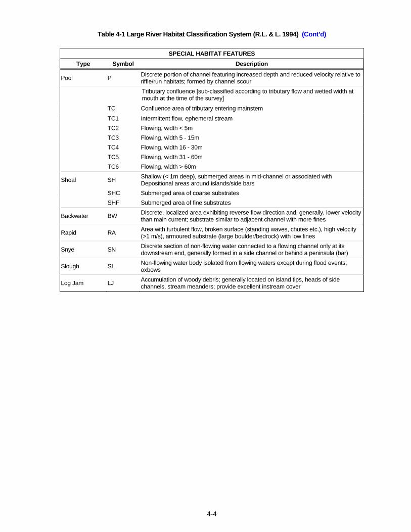
Table 4-1 Large River Habitat Classification System (R.L. & L. 1994) (Cont’d)
4-4
SPECIAL HABITAT FEATURES Type Symbol Description
Pool P Discrete portion of channel featuring increased depth and reduced velocity relative to riffle/run habitats; formed by channel scour
Tributary confluence [sub-classified according to tributary flow and wetted width at mouth at the time of the survey]
TC Confluence area of tributary entering mainstem
TC1 Intermittent flow, ephemeral stream TC2 Flowing, width < 5m TC3 Flowing, width 5 - 15m TC4 Flowing, width 16 - 30m TC5 Flowing, width 31 - 60m TC6 Flowing, width > 60m
Shoal SH Shallow (< 1m deep), submerged areas in mid-channel or associated with Depositional areas around islands/side bars
SHC Submerged area of coarse substrates SHF Submerged area of fine substrates
Backwater BW Discrete, localized area exhibiting reverse flow direction and, generally, lower velocity than main current; substrate similar to adjacent channel with more fines
Rapid RA Area with turbulent flow, broken surface (standing waves, chutes etc.), high velocity (>1 m/s), armoured substrate (large boulder/bedrock) with low fines
Snye SN Discrete section of non-flowing water connected to a flowing channel only at its downstream end, generally formed in a side channel or behind a peninsula (bar)
Slough SL Non-flowing water body isolated from flowing waters except during flood events; oxbows
Log Jam LJ Accumulation of woody debris; generally located on island tips, heads of side channels, stream meanders; provide excellent instream cover
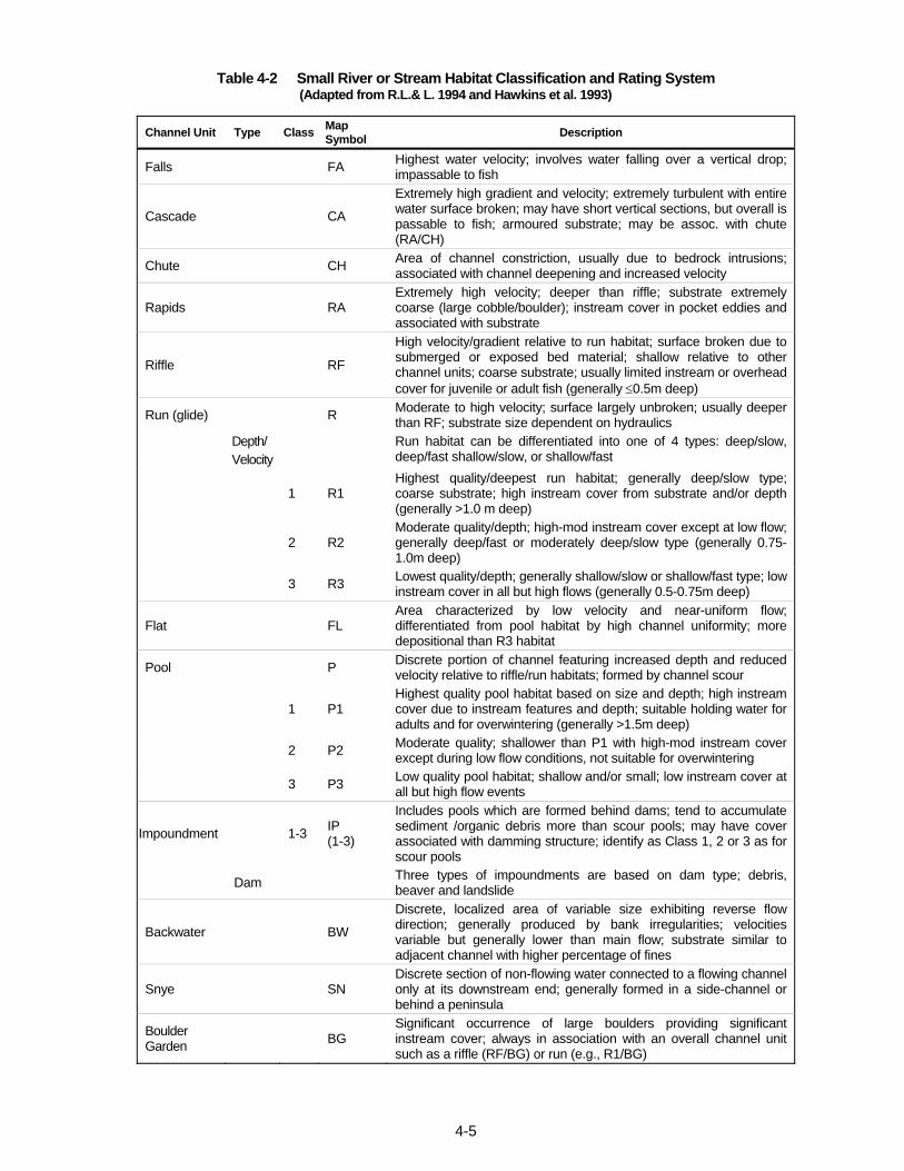
Table 4-2 Small River or Stream Habitat Classification and Rating System (Adapted from R.L.& L. 1994 and Hawkins et al. 1993)
4-5
Channel Unit Type Class Map Symbol Description
Falls FA Highest water velocity; involves water falling over a vertical drop; impassable to fish
Cascade CA
Extremely high gradient and velocity; extremely turbulent with entire water surface broken; may have short vertical sections, but overall is passable to fish; armoured substrate; may be assoc. with chute (RA/CH)
Chute CH Area of channel constriction, usually due to bedrock intrusions; associated with channel deepening and increased velocity
Rapids RA Extremely high velocity; deeper than riffle; substrate extremely coarse (large cobble/boulder); instream cover in pocket eddies and associated with substrate
Riffle RF
High velocity/gradient relative to run habitat; surface broken due to submerged or exposed bed material; shallow relative to other channel units; coarse substrate; usually limited instream or overhead cover for juvenile or adult fish (generally ≤0.5m deep)
Run (glide) R Moderate to high velocity; surface largely unbroken; usually deeper than RF; substrate size dependent on hydraulics
Depth/ Velocity
Run habitat can be differentiated into one of 4 types: deep/slow, deep/fast shallow/slow, or shallow/fast
1 R1 Highest quality/deepest run habitat; generally deep/slow type; coarse substrate; high instream cover from substrate and/or depth (generally >1.0 m deep)
2 R2 Moderate quality/depth; high-mod instream cover except at low flow; generally deep/fast or moderately deep/slow type (generally 0.75-1.0m deep)
3 R3 Lowest quality/depth; generally shallow/slow or shallow/fast type; low instream cover in all but high flows (generally 0.5-0.75m deep)
Flat FL Area characterized by low velocity and near-uniform flow; differentiated from pool habitat by high channel uniformity; more depositional than R3 habitat
Pool P Discrete portion of channel featuring increased depth and reduced velocity relative to riffle/run habitats; formed by channel scour
1 P1 Highest quality pool habitat based on size and depth; high instream cover due to instream features and depth; suitable holding water for adults and for overwintering (generally >1.5m deep)
2 P2 Moderate quality; shallower than P1 with high-mod instream cover except during low flow conditions, not suitable for overwintering
3 P3 Low quality pool habitat; shallow and/or small; low instream cover at all but high flow events
Impoundment 1-3 IP (1-3)
Includes pools which are formed behind dams; tend to accumulate sediment /organic debris more than scour pools; may have cover associated with damming structure; identify as Class 1, 2 or 3 as for scour pools
Dam Three types of impoundments are based on dam type; debris, beaver and landslide
Backwater BW
Discrete, localized area of variable size exhibiting reverse flow direction; generally produced by bank irregularities; velocities variable but generally lower than main flow; substrate similar to adjacent channel with higher percentage of fines
Snye SN Discrete section of non-flowing water connected to a flowing channel only at its downstream end; generally formed in a side-channel or behind a peninsula
Boulder Garden BG
Significant occurrence of large boulders providing significant instream cover; always in association with an overall channel unit such as a riffle (RF/BG) or run (e.g., R1/BG)
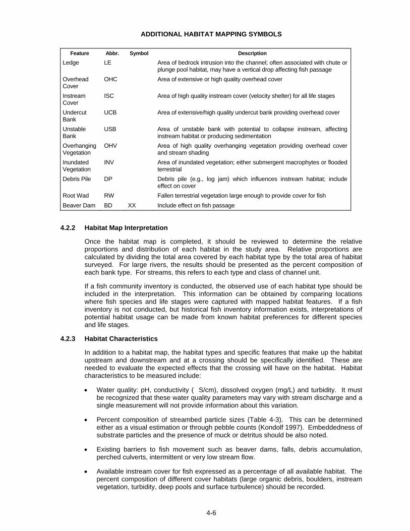
ADDITIONAL HABITAT MAPPING SYMBOLS
4-6
Feature Abbr. Symbol Description
Ledge LE Area of bedrock intrusion into the channel; often associated with chute or plunge pool habitat, may have a vertical drop affecting fish passage
Overhead Cover
OHC Area of extensive or high quality overhead cover
Instream Cover
ISC Area of high quality instream cover (velocity shelter) for all life stages
Undercut Bank
UCB Area of extensive/high quality undercut bank providing overhead cover
Unstable Bank
USB Area of unstable bank with potential to collapse instream, affecting instream habitat or producing sedimentation
Overhanging Vegetation
OHV Area of high quality overhanging vegetation providing overhead cover and stream shading
Inundated Vegetation
INV Area of inundated vegetation; either submergent macrophytes or flooded terrestrial
Debris Pile DP Debris pile (e.g., log jam) which influences instream habitat; include effect on cover
Root Wad RW Fallen terrestrial vegetation large enough to provide cover for fish Beaver Dam BD XX Include effect on fish passage
4.2.2 Habitat Map Interpretation
Once the habitat map is completed, it should be reviewed to determine the relative proportions and distribution of each habitat in the study area. Relative proportions are calculated by dividing the total area covered by each habitat type by the total area of habitat surveyed. For large rivers, the results should be presented as the percent composition of each bank type. For streams, this refers to each type and class of channel unit.
If a fish community inventory is conducted, the observed use of each habitat type should be included in the interpretation. This information can be obtained by comparing locations where fish species and life stages were captured with mapped habitat features. If a fish inventory is not conducted, but historical fish inventory information exists, interpretations of potential habitat usage can be made from known habitat preferences for different species and life stages.
4.2.3 Habitat Characteristics
In addition to a habitat map, the habitat types and specific features that make up the habitat upstream and downstream and at a crossing should be specifically identified. These are needed to evaluate the expected effects that the crossing will have on the habitat. Habitat characteristics to be measured include:
• Water quality: pH, conductivity (�S/cm), dissolved oxygen (mg/L) and turbidity. It must be recognized that these water quality parameters may vary with stream discharge and a single measurement will not provide information about this variation.
• Percent composition of streambed particle sizes (Table 4-3). This can be determined either as a visual estimation or through pebble counts (Kondolf 1997). Embeddedness of substrate particles and the presence of muck or detritus should be also noted.
• Existing barriers to fish movement such as beaver dams, falls, debris accumulation, perched culverts, intermittent or very low stream flow.
• Available instream cover for fish expressed as a percentage of all available habitat. The percent composition of different cover habitats (large organic debris, boulders, instream vegetation, turbidity, deep pools and surface turbulence) should be recorded.
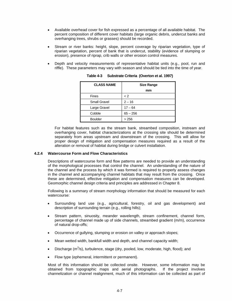
4-7
• Available overhead cover for fish expressed as a percentage of all available habitat. The percent composition of different cover habitats (large organic debris, undercut banks and overhanging trees, shrubs or grasses) should be recorded.
• Stream or river banks: height, slope, percent coverage by riparian vegetation, type of riparian vegetation, percent of bank that is undercut, stability (evidence of slumping or erosion), presence of riprap, crib walls or other erosion control measures.
• Depth and velocity measurements of representative habitat units (e.g., pool, run and riffle). These parameters may vary with season and should be tied into the time of year.
Table 4-3 Substrate Criteria (Overton et al. 1997)
CLASS NAME Size Range mm
Fines < 2
Small Gravel 2 – 16
Large Gravel 17 – 64
Cobble 65 – 256
Boulder > 256
For habitat features such as the stream bank, streambed composition, instream and overhanging cover, habitat characterizations at the crossing site should be determined separately from areas upstream and downstream of the crossing. This will allow for proper design of mitigation and compensation measures required as a result of the alteration or removal of habitat during bridge or culvert installation.
4.2.4 Watercourse Form and Flow Characteristics
Descriptions of watercourse form and flow patterns are needed to provide an understanding of the morphological processes that control the channel. An understanding of the nature of the channel and the process by which it was formed is required to properly assess changes in the channel and accompanying channel habitats that may result from the crossing. Once these are determined, effective mitigation and compensation measures can be developed. Geomorphic channel design criteria and principles are addressed in Chapter 8.
Following is a summary of stream morphology information that should be measured for each watercourse:
• Surrounding land use (e.g., agricultural, forestry, oil and gas development) and description of surrounding terrain (e.g., rolling hills);
• Stream pattern, sinuosity, meander wavelength, stream confinement, channel form, percentage of channel made up of side channels, streambed gradient (m/m), occurrence of natural drop-offs;
• Occurrence of gullying, slumping or erosion on valley or approach slopes;
• Mean wetted width, bankfull width and depth, and channel capacity width;
• Discharge (m3/s), turbulence, stage (dry, pooled, low, moderate, high, flood); and
• Flow type (ephemeral, intermittent or permanent).
Most of this information should be collected onsite. However, some information may be obtained from topographic maps and aerial photographs. If the project involves channelization or channel realignment, much of this information can be collected as part of
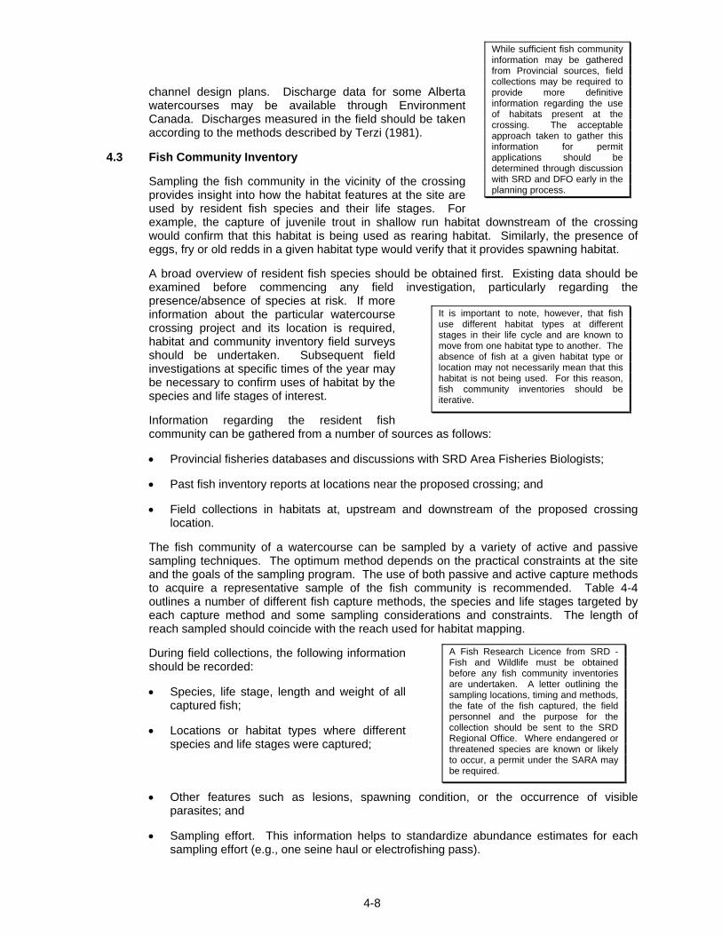
4-8
It is important to note, however, that fish use different habitat types at different stages in their life cycle and are known to move from one habitat type to another. The absence of fish at a given habitat type or location may not necessarily mean that this habitat is not being used. For this reason, fish community inventories should be iterative.
While sufficient fish community information may be gathered from Provincial sources, field collections may be required to provide more definitive information regarding the use of habitats present at the crossing. The acceptable approach taken to gather this information for permit applications should be determined through discussion with SRD and DFO early in the planning process.
A Fish Research Licence from SRD - Fish and Wildlife must be obtained before any fish community inventories are undertaken. A letter outlining the sampling locations, timing and methods, the fate of the fish captured, the field personnel and the purpose for the collection should be sent to the SRD Regional Office. Where endangered or threatened species are known or likely to occur, a permit under the SARA may be required.
channel design plans. Discharge data for some Alberta watercourses may be available through Environment Canada. Discharges measured in the field should be taken according to the methods described by Terzi (1981).
4.3 Fish Community Inventory
Sampling the fish community in the vicinity of the crossing provides insight into how the habitat features at the site are used by resident fish species and their life stages. For example, the capture of juvenile trout in shallow run habitat downstream of the crossing would confirm that this habitat is being used as rearing habitat. Similarly, the presence of eggs, fry or old redds in a given habitat type would verify that it provides spawning habitat.
A broad overview of resident fish species should be obtained first. Existing data should be examined before commencing any field investigation, particularly regarding the presence/absence of species at risk. If more information about the particular watercourse crossing project and its location is required, habitat and community inventory field surveys should be undertaken. Subsequent field investigations at specific times of the year may be necessary to confirm uses of habitat by the species and life stages of interest.
Information regarding the resident fish community can be gathered from a number of sources as follows:
• Provincial fisheries databases and discussions with SRD Area Fisheries Biologists;
• Past fish inventory reports at locations near the proposed crossing; and
• Field collections in habitats at, upstream and downstream of the proposed crossing location.
The fish community of a watercourse can be sampled by a variety of active and passive sampling techniques. The optimum method depends on the practical constraints at the site and the goals of the sampling program. The use of both passive and active capture methods to acquire a representative sample of the fish community is recommended. Table 4-4 outlines a number of different fish capture methods, the species and life stages targeted by each capture method and some sampling considerations and constraints. The length of reach sampled should coincide with the reach used for habitat mapping.
During field collections, the following information should be recorded:
• Species, life stage, length and weight of all captured fish;
• Locations or habitat types where different species and life stages were captured;
• Other features such as lesions, spawning condition, or the occurrence of visible parasites; and
• Sampling effort. This information helps to standardize abundance estimates for each sampling effort (e.g., one seine haul or electrofishing pass).
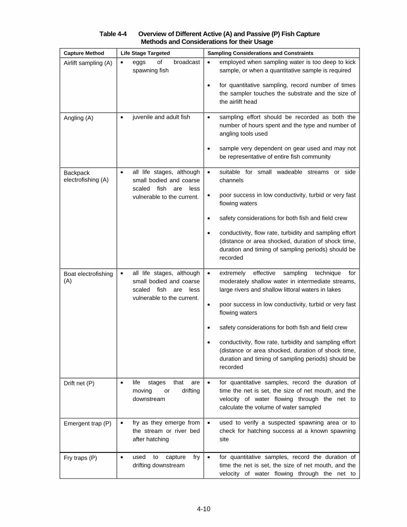
Table 4-4 Overview of Different Active (A) and Passive (P) Fish Capture Methods and Considerations for their Usage
4-10
Capture Method Life Stage Targeted Sampling Considerations and Constraints
Airlift sampling (A) • eggs of broadcast spawning fish
• employed when sampling water is too deep to kick sample, or when a quantitative sample is required
• for quantitative sampling, record number of times the sampler touches the substrate and the size of the airlift head
Angling (A) • juvenile and adult fish • sampling effort should be recorded as both the number of hours spent and the type and number of angling tools used
• sample very dependent on gear used and may not be representative of entire fish community
Backpack electrofishing (A)
• all life stages, although small bodied and coarse scaled fish are less vulnerable to the current.
• suitable for small wadeable streams or side channels
• poor success in low conductivity, turbid or very fast flowing waters
• safety considerations for both fish and field crew
• conductivity, flow rate, turbidity and sampling effort (distance or area shocked, duration of shock time, duration and timing of sampling periods) should be recorded
Boat electrofishing (A)
• all life stages, although small bodied and coarse scaled fish are less vulnerable to the current.
• extremely effective sampling technique for moderately shallow water in intermediate streams, large rivers and shallow littoral waters in lakes
• poor success in low conductivity, turbid or very fast flowing waters
• safety considerations for both fish and field crew
• conductivity, flow rate, turbidity and sampling effort (distance or area shocked, duration of shock time, duration and timing of sampling periods) should be recorded
Drift net (P) • life stages that are moving or drifting downstream
• for quantitative samples, record the duration of time the net is set, the size of net mouth, and the velocity of water flowing through the net to calculate the volume of water sampled
Emergent trap (P) • fry as they emerge from the stream or river bed after hatching
• used to verify a suspected spawning area or to check for hatching success at a known spawning site
Fry traps (P) • used to capture fry drifting downstream
• for quantitative samples, record the duration of time the net is set, the size of net mouth, and the velocity of water flowing through the net to
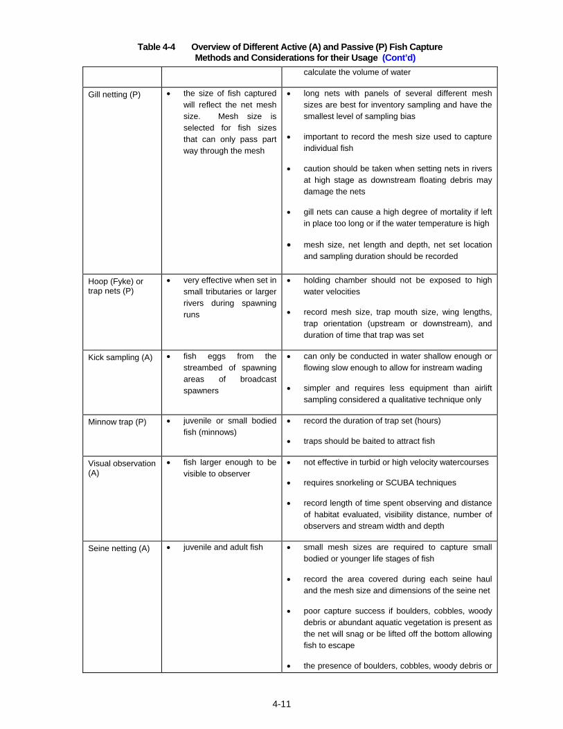
Table 4-4 Overview of Different Active (A) and Passive (P) Fish Capture Methods and Considerations for their Usage (Cont’d)
4-11
calculate the volume of water
Gill netting (P) • the size of fish captured will reflect the net mesh size. Mesh size is selected for fish sizes that can only pass part way through the mesh
• long nets with panels of several different mesh sizes are best for inventory sampling and have the smallest level of sampling bias
• important to record the mesh size used to capture individual fish
• caution should be taken when setting nets in rivers at high stage as downstream floating debris may damage the nets
• gill nets can cause a high degree of mortality if left in place too long or if the water temperature is high
• mesh size, net length and depth, net set location and sampling duration should be recorded
Hoop (Fyke) or trap nets (P)
• very effective when set in small tributaries or larger rivers during spawning runs
• holding chamber should not be exposed to high water velocities
• record mesh size, trap mouth size, wing lengths, trap orientation (upstream or downstream), and duration of time that trap was set
Kick sampling (A) • fish eggs from the streambed of spawning areas of broadcast spawners
• can only be conducted in water shallow enough or flowing slow enough to allow for instream wading
• simpler and requires less equipment than airlift sampling considered a qualitative technique only
Minnow trap (P) • juvenile or small bodied fish (minnows)
• record the duration of trap set (hours)
• traps should be baited to attract fish
Visual observation (A)
• fish larger enough to be visible to observer
• not effective in turbid or high velocity watercourses
• requires snorkeling or SCUBA techniques
• record length of time spent observing and distance of habitat evaluated, visibility distance, number of observers and stream width and depth
Seine netting (A) • juvenile and adult fish • small mesh sizes are required to capture small bodied or younger life stages of fish
• record the area covered during each seine haul and the mesh size and dimensions of the seine net
• poor capture success if boulders, cobbles, woody debris or abundant aquatic vegetation is present as the net will snag or be lifted off the bottom allowing fish to escape
• the presence of boulders, cobbles, woody debris or
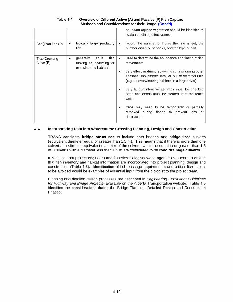
Table 4-4 Overview of Different Active (A) and Passive (P) Fish Capture Methods and Considerations for their Usage (Cont’d)
4-12
abundant aquatic vegetation should be identified to evaluate seining effectiveness
Set (Trot) line (P) • typically large predatory fish
• record the number of hours the line is set, the number and size of hooks, and the type of bait
Trap/Counting fence (P)
• generally adult fish moving to spawning or overwintering habitats
• used to determine the abundance and timing of fish movements
• very effective during spawning runs or during other seasonal movements into, or out of watercourses (e.g., to overwintering habitats in a larger river)
• very labour intensive as traps must be checked often and debris must be cleared from the fence walls
• traps may need to be temporarily or partially removed during floods to prevent loss or destruction
4.4 Incorporating Data into Watercourse Crossing Planning, Design and Construction
TRANS considers bridge structures to include both bridges and bridge-sized culverts (equivalent diameter equal or greater than 1.5 m). This means that if there is more than one culvert at a site, the equivalent diameter of the culverts would be equal to or greater than 1.5 m. Culverts with a diameter less than 1.5 m are considered to be road drainage culverts.
It is critical that project engineers and fisheries biologists work together as a team to ensure that fish inventory and habitat information are incorporated into project planning, design and construction (Table 4-5). Identification of fish passage requirements and critical fish habitat to be avoided would be examples of essential input from the biologist to the project team.
Planning and detailed design processes are described in Engineering Consultant Guidelines for Highway and Bridge Projects- available on the Alberta Transportation website. Table 4-5 identifies the considerations during the Bridge Planning, Detailed Design and Construction Phases.
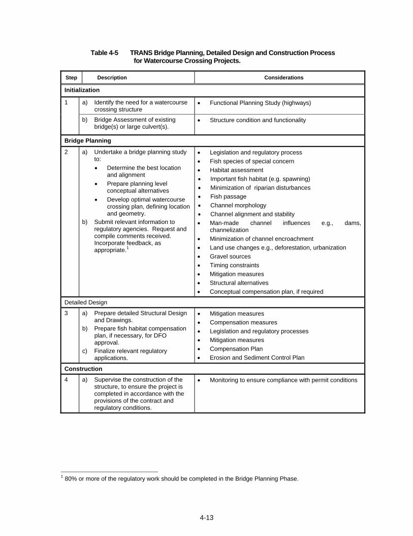
4-13
Table 4-5 TRANS Bridge Planning, Detailed Design and Construction Process for Watercourse Crossing Projects.
Step Description Considerations
Initialization
a) Identify the need for a watercourse crossing structure
• Functional Planning Study (highways) 1
b) Bridge Assessment of existing bridge(s) or large culvert(s).
• Structure condition and functionality
Bridge Planning
2 a) Undertake a bridge planning study to: • Determine the best location
and alignment • Prepare planning level
conceptual alternatives • Develop optimal watercourse
crossing plan, defining location and geometry.
b) Submit relevant information to regulatory agencies. Request and compile comments received. Incorporate feedback, as appropriate.1
• Legislation and regulatory process • Fish species of special concern • Habitat assessment • Important fish habitat (e.g. spawning) • Minimization of riparian disturbances • Fish passage • Channel morphology • Channel alignment and stability • Man-made channel influences e.g., dams,
channelization • Minimization of channel encroachment • Land use changes e.g., deforestation, urbanization • Gravel sources • Timing constraints • Mitigation measures • Structural alternatives • Conceptual compensation plan, if required
Detailed Design
3 a) Prepare detailed Structural Design and Drawings.
b) Prepare fish habitat compensation plan, if necessary, for DFO approval.
c) Finalize relevant regulatory applications.
• Mitigation measures • Compensation measures • Legislation and regulatory processes • Mitigation measures • Compensation Plan • Erosion and Sediment Control Plan
Construction
4 a) Supervise the construction of the structure, to ensure the project is completed in accordance with the provisions of the contract and regulatory conditions.
• Monitoring to ensure compliance with permit conditions
1 80% or more of the regulatory work should be completed in the Bridge Planning Phase.
4-14
4.4.1 Functional Planning Study
The Functional Planning Study is generally undertaken for new highway routes, twinning, relocations or major upgrades. If there is a federal trigger (see Section 2.2.3), the study will need to include an environmental assessment that meets the requirements of the Canadian Environmental Assessment Act.
At this level of planning only a general location and alignment, and in some cases the structure type (i.e., bridge or culvert) are identified for the watercourse crossing. A specific structure design and fish habitat compensation measures are not yet available for submission to regulatory agencies. These would follow in the bridge planning and design phases. Nevertheless, early consultation with regulatory agencies may be recommended by the project sponsor to help identify any concerns with the project (e.g., alignment or location) and allow mitigation options to be developed. An example of a mitigation measure arising from early consultation would be the relocation of the crossing site to avoid critical fish spawning habitat.
The Functional Planning Study is followed by the Bridge Planning Phase for identified crossings. In some cases, there may be a significant amount of time between the Functional Planning Study and the Bridge Planning Phase. Immediate follow up to a Functional Planning Study may focus on protection of right-of way and identification of land purchase requirements.
4.4.2 Bridge Assessments and Planning
The vast majority of watercourse crossing projects entail the determination of the best course of action for existing crossing structures.
A Bridge Assessment is a formal review of existing crossing structure condition and functionality with respect to the crossing and roadway approaches. A recommendation is developed based on the findings of the assessment. Possible outcomes include maintenance, rehabilitation, replacement, widening or elimination of the existing structure.
Once a strategy for the crossing(s) is selected (e.g., replacement of the existing structure), the Bridge Assessment is followed by the Bridge Planning Phase. Conceptual planning level alternatives are developed and evaluated. Generally, one concept is selected and Design Data (DD) drawings are prepared. The DD drawings provide all significant information needed for structural design and associated river engineering in the subsequent design phase. Occasionally, two sets of DDs may be prepared for different conceptual options that have been developed.
Once the DDs for the crossing have been completed and specific mitigation measures selected for the site, all potential sources of residual HADD are identified. If DFO considers the residual HADD unacceptable based on DFO’s risk matrix, the crossing alignment, design and construction method may be re-evaluated.
The consultant is responsible for undertaking any applicable environmental assessments and for early communication with regulatory agencies regarding the nature of the project, environmental impacts and conceptual mitigation and compensation measures.
Detailed information on Bridge Assessments and Bridge Planning can be found in Section 10 of Engineering Consultant Guidelines for Highway and Bridge Projects, on the Alberta Transportation website.
4.4.3 Design Phase
The fish community inventory, habitat assessment and stream morphology data are used in the design phase to finalize mitigation and compensation measures that are in line with the fisheries management objectives for the watercourse. Mitigation measures in this phase place constraints on the design to avoid or minimize HADD of fish habitat and impacts to fish.
4-15
If a HADD cannot be avoided, compensation measures must be developed to ensure that no net loss in fish habitat is achieved.
Mitigation and compensation measures are discussed more fully in Chapters 5 and 6, respectively. Examples of recommended mitigation and compensation measures are presented in the Factsheets in Appendix I and II.
The consultant is responsible for summarizing the above information, preparing any formal applications for signature by the Project Sponsor of TRANS, and obtaining approvals from the environmental regulatory agencies. The conditions of the regulatory approvals are generally included in the tender documents as well as mitigative measures that have been identified such as Best Management Practices (BMPs) that limit the adverse effects of construction activities on fish and fish habitat.
4.4.4 Construction Phase
Activities during the construction phase are the outcome of the inventory, assessment and application of the data to the design. During construction applicable regulatory conditions are fulfilled as well as construction of the proposed compensation measures.
CHAPTER 5
5-i
TABLE OF CONTENTS 5. MITIGATION PROCEDURES............................................................................................... 5-1
5.1 Introduction .................................................................................................................. 5-1
5.1.1 Mitigation during Initial Planning ........................................................................ 5-1
5.1.2 Mitigation during Detailed Design....................................................................... 5-1
5.1.3 Instream Timing Constraints ............................................................................... 5-2
5.2 Bridges ......................................................................................................................... 5-2
5.3 Culverts ......................................................................................................................... 5-2
5.4 Ford Crossings and Ice Bridges................................................................................. 5-3
5.4.1 Ford Crossings ..................................................................................................... 5-2
5.4.2 Ice Bridges............................................................................................................. 5-2
5.5 Stream Realignment and Channelization .................................................................. 5-3
5.6 Shore Protection .......................................................................................................... 5-4
5.7 Road and Stream Crossing Maintenance Activities................................................. 5-6
LIST OF TABLES
Table 5-1 Mitigation for Bridges, Culverts, Stream Realignment and Channelization and Shore Protection Works..................................................................................... 5-5
Table 5-2 Mitigation for Watercourse Crossing Structure Maintenance Activities ............. 5-5

5-ii
Page left blank intentionally
5-1
5. MITIGATION PROCEDURES
5.1 Introduction
The DFO’s Policy for the Management of Fish Habitat defines mitigation as those actions taken during the planning, design, construction and operation of a project that alleviate or avoid potential adverse effects on fish habitat. Mitigation can consist of a number of actions:
• relocation;
• incorporation of design features which eliminate or reduce negative impacts; and
• construction Best Management Practices (BMPs) and preventative measures.
Relocation and redesign are mitigation measures that are used in the planning and design stages of the project while BMPs and other preventative measures are applicable to project construction and operation.
DFO defines compensation as those measures which are implemented to offset any residual adverse effects remaining after implementation of mitigation measures. Compensation procedures are covered in Chapter 6.
Mitigation in the provincial context, or as part of an environmental assessment under CEAA, has a somewhat different meaning in that it may include both mitigation and compensation measures.
5.1.1 Mitigation during Initial Planning
The most effective and preferred mitigation procedure is to locate and configure a structure during the initial planning stages such that impacts on fish and fish habitat are avoided. For example, locating a structure downstream of a known fish spawning area may prevent adverse effects on the spawning habitat. Similarly, changing the design of a culvert from corrugated steel to one with open footings will mitigate adverse effects associated with fish passage or losses of streambed habitat. These measures used to avoid a HADD may not always be feasible or practical. Consequently, the option that results in the least impact on fish and fish habitat, within the constraints of the overall project, should be selected. Planning studies should therefore include documentation to show that fish and fish habitat were considered as factors in route selection and planning.
5.1.2 Mitigation during Detailed Design
BMPs should be prescribed during detailed design and used routinely when working in and around watercourses to prevent a HADD. They are generic and should be used for all water crossing construction and maintenance projects. BMPs for erosion and sediment control are described in the TRANS documents Design Guidelines for Erosion and Sediment Control for Highways and Field Guide for Erosion and Sediment Control for Highways. Both documents can be found on the Alberta Transportation website. Examples of work site isolation methods are described in Appendix I of this manual, and are addressed in the DFO Operational Statement, Isolated or Dry Open-cut Stream Crossings which may be found on the DFO website.
In addition to using BMPs, specific mitigation measures should also be included in the detailed design. Selection of the specific mitigation measures must account for construction and maintenance activities as well as the expected effects of the completed structure on fish and fish habitat. The causes of potential HADD for different types of water crossing projects and activities and recommended mitigation measures are discussed in the following sections.
5-2
5.1.3 Instream Timing Constraints
Alberta Sustainable Resource Development (SRD), Fisheries and Wildlife Management Division, has assigned allowable periods of the year when instream construction may occur in Alberta watercourses. These are based on the fish community present in the watercourse. The intent of instream timing constraints is to protect certain fish species during critical spawning, egg incubation, hatching and migration periods from activities associated with construction in and around watercourses. Specifically, these are designed to protect against those activities that could obstruct fish passage, cause direct lethal effects on adult fish and incubating eggs and fry, or reduce the productivity of fish food items such as benthic stream invertebrates (e.g., mayflies and caddis flies).
The SRD Management Area Maps that form part of the Code of Practice for Watercourse Crossings show classes of water bodies and their specific timing constraints. The Management Area Maps can be viewed on the Alberta Environment website: (http://www.environment.alberta.ca/1398.html)
5.2 Bridges
Bridge construction can adversely affect fish and fish habitat as a result of instream construction activities and permanent structures associated with the bridge (e.g., piers or shore protection). Specific impacts to fish habitat due to changes in sediment release and channel morphology are discussed in Section 3.2. Table 5-1 outlines references for mitigation options to minimize or eliminate adverse effects to fish and fish habitat. Clear span bridges that do not encroach on the stream channel and ice bridges are covered by DFO Operational Statements (see Section 2.2.1.2). If the mitigation measures specified in the Operational Statement are implemented, no HADD of habitat is deemed to occur.
5.3 Culverts
As with bridge construction, culvert installation may cause adverse affects on fish and fish habitat as a result of instream construction activities and the placement of permanent instream structures (e.g., the culvert).
If culverts are improperly designed or constructed, long-term impacts to fish and fish habitat can occur. Fish passage can be impeded by the following factors:
• excessive water velocity at the inlet, outlet and within the culvert;
• inadequate water depth in and downstream of the culvert;
• excessive height of the culvert outlet invert above the streambed and possibly the water surface; and
• lack of resting zones upstream of the culvert.
Culverts installed with deep depressed inlets may initiate head-cutting or the development of upstream ledges as the upstream channel adjusts to the lower elevation of the culvert inlet. This can modify the channel morphology; eroding material from the bed and banks, temporarily introducing it into the water column, and transporting it downstream. Sediment released during culvert installation can negatively affect downstream habitats as a result of sediment deposition. Specific impacts to fish habitat due to culvert construction are discussed in Section 3.2.
References for mitigation options to avoid such impacts to fish and fish habitat are outlined in Table 5-1.
5-3
5.4 Ford Crossings and Ice Bridges
5.4.1 Ford Crossings
Ford crossings are natural, shallow water crossings used for low frequency access during low flow conditions. Fish habitat concerns resulting from the use of this type of crossing include disturbance of the streambed and bank resulting in sediment entrainment, as well as pollution from machinery. Special measures may be required to ensure fish passage if the ford crossing is above the natural streambed. Mitigation measures for ford crossings include:
• Select sites with firm streambed to minimize release of sediment from traffic. Ford crossings in areas of soft substrates should be avoided. Where soft substrates are present alternative crossing methods should be considered. The streambed at the crossing site should consist of bedrock or large gravel or cobble material.
• Approaches to the crossing should be stable and have a low slope. Avoid the development of ford crossings where active channel streambanks exceed two metres height at the site of the crossing.
• Limit crossings to a single location.
• Spawning areas must be avoided.
• Ford crossings should be constructed and used during low flow conditions.
• All activity must be conducted in such a manner that silt does not enter streams.
• Avoid locating ford crossings on the outside of sharp bends unless the banks are stable.
• Before abandonment, the streambed and banks should be restored and stabilized to prevent long-term erosion and subsequent siltation.
• Ensure that pollutants from the machinery using the crossing do not enter the stream.
5.4.2 Ice Bridges
Ice bridges are temporary stream crossings that can be constructed using ice, snow and, in some cases, reinforcing material such as logs. Proper location of the crossing and good construction techniques will minimize siltation potential for this type of crossing. Effects of ice bridges on fish habitat are generally minimal. Most are associated with bank disturbances resulting from construction or maintenance of the approaches and the release of toxic material through spills or accidents. Ice bridges and snow fills are covered by a DFO Operational Statement. If the mitigation measures specified in the Operational Statement are implemented, no HADD of habitat is deemed to occur.
5.5 Stream Realignment and Channelization
Stream realignment and channelization can negatively affect fish and fish habitat as a result of lost habitat, changes in channel hydraulics and increased sediment loading during and after construction. Habitat can be lost as a direct result of the removal of fish habitat during stream realignment or channelization. Simplification of habitat type during channelization has been linked to reductions in fish and benthic invertebrate biomass and diversity (OMNR 1994). Improper design may result in changes in flow levels and patterns may also result in increased erosion of downstream banks and therefore increased sediment loading. Impacts associated with increased sediment loading can also occur during and after construction of the new channel. References for mitigation options that can be employed to minimize impacts to fish and fish habitat are presented in Tables 5-1 and 5.2.
5-4
5.6 Shore Protection
Shoreline protection can result in the loss of habitat due to instream construction and modify the downstream hydraulics (e.g. flow patterns). There is a risk of increased sediment loading during site preparation, construction if proper mitigative measures are not taken. Post construction increases in bank erosion may occur as a result of improper design or poor construction practices. Shore protection may also result in a loss of fish habitat as physical protection structures encroach into the watercourse. Mitigation options to be employed during the design and construction of shore protection are outlined in Table 5-1.
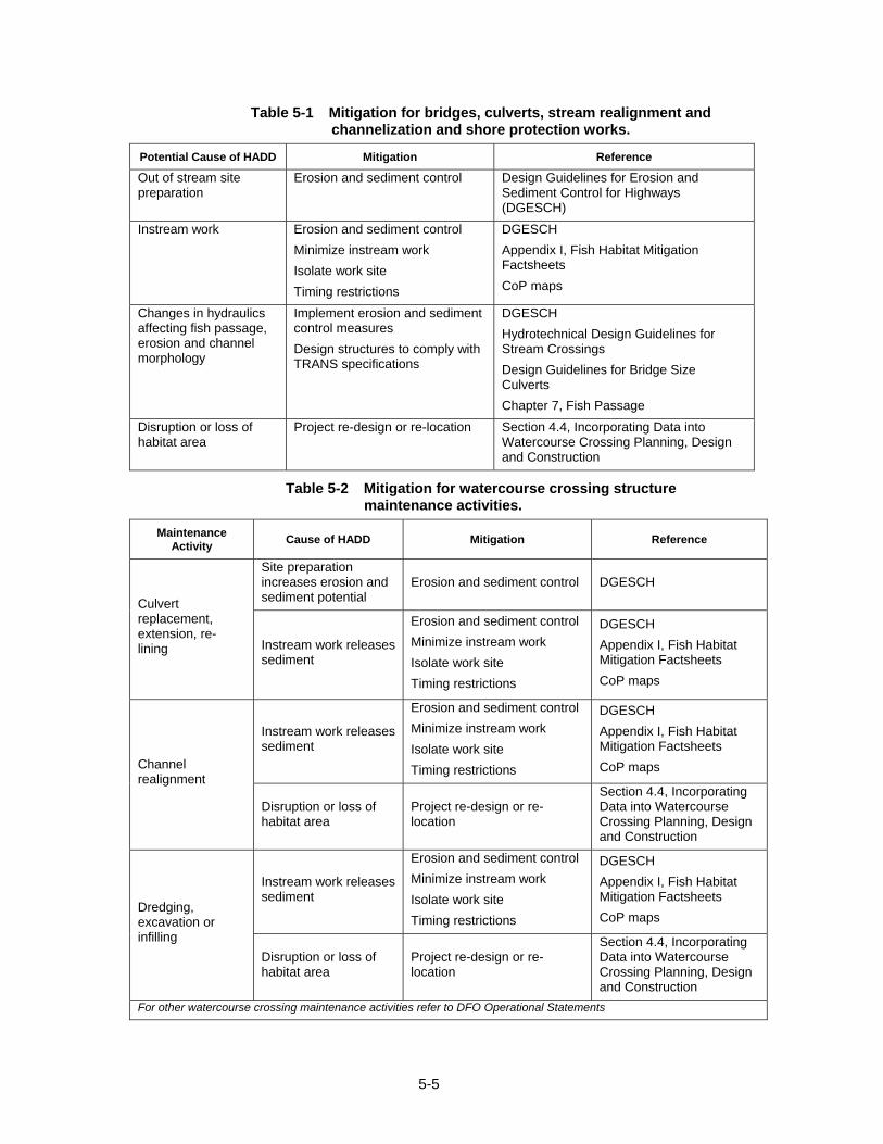
5-5
Table 5-1 Mitigation for bridges, culverts, stream realignment and channelization and shore protection works.
Potential Cause of HADD Mitigation Reference
Out of stream site preparation
Erosion and sediment control Design Guidelines for Erosion and Sediment Control for Highways (DGESCH)
Instream work Erosion and sediment control Minimize instream work Isolate work site Timing restrictions
DGESCH Appendix I, Fish Habitat Mitigation Factsheets CoP maps
Changes in hydraulics affecting fish passage, erosion and channel morphology
Implement erosion and sediment control measures Design structures to comply with TRANS specifications
DGESCH Hydrotechnical Design Guidelines for Stream Crossings Design Guidelines for Bridge Size Culverts Chapter 7, Fish Passage
Disruption or loss of habitat area
Project re-design or re-location Section 4.4, Incorporating Data into Watercourse Crossing Planning, Design and Construction
Table 5-2 Mitigation for watercourse crossing structure maintenance activities.
Maintenance Activity Cause of HADD Mitigation Reference
Site preparation increases erosion and sediment potential
Erosion and sediment control DGESCH
Culvert replacement, extension, re-lining Instream work releases
sediment
Erosion and sediment control Minimize instream work Isolate work site Timing restrictions
DGESCH Appendix I, Fish Habitat Mitigation Factsheets CoP maps
Instream work releases sediment
Erosion and sediment control Minimize instream work Isolate work site Timing restrictions
DGESCH Appendix I, Fish Habitat Mitigation Factsheets CoP maps Channel
realignment
Disruption or loss of habitat area
Project re-design or re-location
Section 4.4, Incorporating Data into Watercourse Crossing Planning, Design and Construction
Instream work releases sediment
Erosion and sediment control Minimize instream work Isolate work site Timing restrictions
DGESCH Appendix I, Fish Habitat Mitigation Factsheets CoP maps
Dredging, excavation or infilling
Disruption or loss of habitat area
Project re-design or re-location
Section 4.4, Incorporating Data into Watercourse Crossing Planning, Design and Construction
For other watercourse crossing maintenance activities refer to DFO Operational Statements
5-6
5.7 Road and Stream Crossing Maintenance Activities
Many routine road and stream crossing maintenance activities have the potential to adversely affect fish and fish habitat. The sources of these effects are discussed in Section 3. It is important that ditches, slopes and culverts be inspected on a regular basis and that recommended mitigation measures are implemented when required maintenance is carried out. Please refer to the TRANS website for more information pertaining to bridge and culvert inspection and maintenance.
The adverse effects of most road maintenance activities can be mitigated to the point where there is no HADD. DFO has issued Operational Statements for culvert maintenance, bridge maintenance, beaver dam removal and maintenance of riparian vegetation in existing rights-of-way. Watercourse crossing maintenance activities not subject to an Operational Statement, sources of potential HADD and suggested mitigation measures are presented in Table 5-2.
CHAPTER 6
6-i
TABLE OF CONTENTS 6. COMPENSATION PROCEDURES.........................................................................6-1
6.1 Introduction .....................................................................................................6-1
6.2 Development of Compensation Measures....................................................6-2
6.3 Selection of Target Species or Community..................................................6-2
6.4 Compensation Objectives..............................................................................6-2
6.5 Conceptual Design .........................................................................................6-3
LIST OF TABLES Table 6-1 Example Techniques to Compensate for Residual HADD.......................6-4

6-ii
Page left blank intentionally
6-1
6. COMPENSATION PROCEDURES
6.1 Introduction
The implementation of mitigation measures described in the previous section will often be sufficient to avoid HADD from construction and maintenance of watercourse crossings. However, in some cases, HADD cannot be avoided or may still occur in spite of these measures. If the residual negative effects are likely to have a medium or high risk of causing HADD (Figure 2-2), the HADD must be Authorized by DFO to avoid the contravention of subsection 35(1) of the Fisheries Act.
In keeping with the guiding principle of no net loss, DFO will only issue Authorizations on the condition that measures to compensate for the HADD are implemented by the proponent. In other words, a compensation plan must accompany an application for an Authorization for HADD. Compensation measures are those actions intended to offset any residual adverse effects remaining after implementation of mitigation measures.
Significant or unacceptable negative effects remaining after implementation of mitigation measures could result in DFO not issuing an Authorization, but instead requesting the proponent to redesign or relocate the project.
Compensation involves the replacement of damaged habitat with newly created habitat or the enhancement of existing habitat. DFO defines the compensation options that are available (DFO, Practitioners Guide to Habitat Compensation, 2007). These include (in order of preference):
1. Create or increase the productive capacity of like-for-like habitat in the same ecological unit;
2. Create or increase the productive capacity of unlike habitat in the same ecological unit;
3. Create or increase the productive capacity of habitat in a different ecological unit;
4. As a last resort, use artificial production techniques to maintain a stock of fish, deferred compensation or restoration of chemically contaminated sites.
Where ecological unit is defined as: Populations of organisms considered together with their physical environment and the interacting processes among them.
Road allowances and property restrictions may prevent offsite habitat creation or enhancement from being viable compensation options for watercourse crossing and maintenance projects. However it is also possible to locate compensation sites elsewhere on the watercourse or adjacent watercourses that have been disturbed by other land use activities that would benefit from habitat creation or enhancement.
Numerous compensation measures are listed in the literature. A representative range of examples of compensation measures for HADD resulting from watercourse crossing construction projects are outlined in Factsheets in Appendix II. The information presented in the Factsheets provides guidance on the use and applicability of each measure as well as design considerations for implementation.
Adequate compensation for one project will not necessarily be adequate for a similar project on a different watercourse. Although the project may be identical, the fish species and habitat affected may be entirely different. For this reason, compensation measures should be developed on a project-specific basis and must take into account the biological and physical characteristics of the site.
6-2
6.2 Development of Compensation Measures
A number of factors must be considered in developing effective and defensible compensation plans. A multi-disciplinary approach is required. Knowledge of biology, fluvial geomorphology, hydrology, channel hydraulics and engineering must be brought together in the development of compensation measures. Biological concepts must be translated into feasible engineering solutions that are compatible with river hydrology and channel processes. There is no single prescriptive method. Much depends on the nature of the project, the existing habitat at the site and how it is affected by the project, hydrology and channel conditions as well as the knowledge and experience of the practitioners. Early consultation with biologists from DFO regarding a compensation plan is advised once it is apparent a HADD will occur for a project. This early consultation may save time over the long run in receiving regulatory approval from DFO.
The compensation plan should describe the habitat that will be lost, measures to be implemented to compensate for the lost productive capacity in habitat, the rationale to support claims that the plan will be effective, and any follow-up monitoring program to verify the effectiveness of the compensation plan.
Monitoring should include baseline information, and an assessment of the effectiveness of completed compensation, and a timetable for reporting results to DFO. For very small projects, basic compliance monitoring may entail creating a record of photographs from the project site.
If over the course of the monitoring it is determined that the conditions of the compensation plan have not been met or the compensation is not functioning as intended, DFO may require that adjustments and/or contingency plans are implemented.
6.3 Selection of Target Species or Community
The determination of the target species or fish community is an important step in developing a compensation plan. The target species or fish community drives the selection of the type of compensation measures that will be used in the compensation plan. Information about the existing fish community and the fisheries management objectives for the waterbody, where they are available, are considered. All fish species in the community and their interactions with each other should be considered when formulating a compensation strategy. For example, the limiting factor for bull trout in a stream could be the lack of rearing area for mountain whitefish, its primary prey. The establishment of bull trout rearing habitat at the expense of mountain whitefish rearing habitat would not fulfill the overall fisheries management objective for bull trout.
6.4 Compensation Objectives
Habitat requirements of the target species, or species representing the fish community, the quality and quantity of existing habitat in the affected reach, and the habitat affected by the project are the biological design criteria that will be used to determine, in consultation with DFO and SRD, the objectives of the compensation plan. For example, the location of footings for a bridge will remove some of the spawning habitat for northern pike, the target species. Northern pike are known to spawn on vegetated hummock just after ice out. Pike fry require dense, submerged vegetation immediately adjacent to the spawning habitat. The site has an ample supply of spawning habitat, but nursery habitat is limited. In this example the compensation objective would be to enhance or develop nursery habitat for pike. Compensation objectives would typically be included in the conditions of the Authorization for the project issued by DFO.
6-3
6.5 Conceptual Design
Table 6-1 suggests some measures that can be used to compensate for residual HADD of habitat. Examples of compensation measures are also outlined in the corresponding Appendix II Factsheets. The compensation methods presented in the Factsheets can be used alone or in combination to develop a project-specific conceptual design for the compensation plan. Although the Factsheets present examples of compensation techniques typically used to offset losses of habitat from watercourse crossing projects, there are many other compensation methods which can be used to meet the compensation goals.
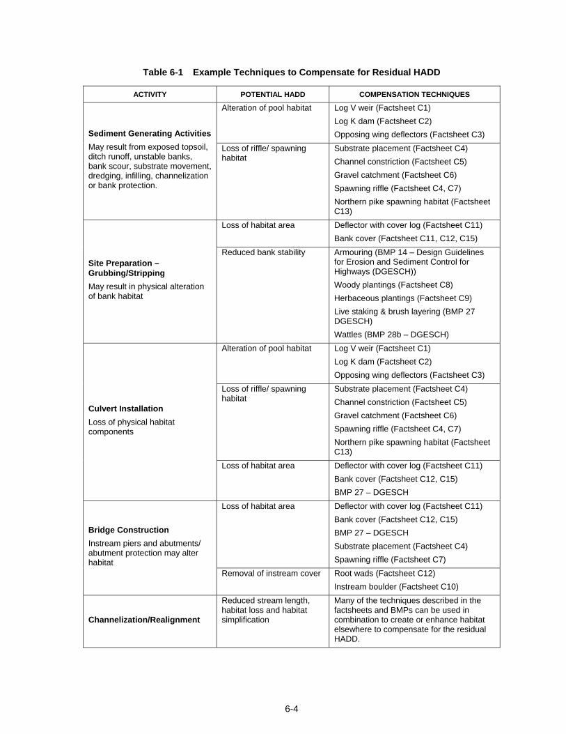
6-4
Table 6-1 Example Techniques to Compensate for Residual HADD
ACTIVITY POTENTIAL HADD COMPENSATION TECHNIQUES
Alteration of pool habitat Log V weir (Factsheet C1) Log K dam (Factsheet C2) Opposing wing deflectors (Factsheet C3) Sediment Generating Activities
May result from exposed topsoil, ditch runoff, unstable banks, bank scour, substrate movement, dredging, infilling, channelization or bank protection.
Loss of riffle/ spawning habitat
Substrate placement (Factsheet C4) Channel constriction (Factsheet C5) Gravel catchment (Factsheet C6) Spawning riffle (Factsheet C4, C7) Northern pike spawning habitat (Factsheet C13)
Loss of habitat area Deflector with cover log (Factsheet C11) Bank cover (Factsheet C11, C12, C15)
Site Preparation – Grubbing/Stripping May result in physical alteration of bank habitat
Reduced bank stability Armouring (BMP 14 – Design Guidelines for Erosion and Sediment Control for Highways (DGESCH)) Woody plantings (Factsheet C8) Herbaceous plantings (Factsheet C9) Live staking & brush layering (BMP 27 DGESCH) Wattles (BMP 28b – DGESCH)
Alteration of pool habitat Log V weir (Factsheet C1) Log K dam (Factsheet C2) Opposing wing deflectors (Factsheet C3)
Loss of riffle/ spawning habitat
Substrate placement (Factsheet C4) Channel constriction (Factsheet C5) Gravel catchment (Factsheet C6) Spawning riffle (Factsheet C4, C7) Northern pike spawning habitat (Factsheet C13)
Culvert Installation Loss of physical habitat components
Loss of habitat area Deflector with cover log (Factsheet C11) Bank cover (Factsheet C12, C15) BMP 27 – DGESCH
Loss of habitat area Deflector with cover log (Factsheet C11) Bank cover (Factsheet C12, C15) BMP 27 – DGESCH Substrate placement (Factsheet C4) Spawning riffle (Factsheet C7)
Bridge Construction Instream piers and abutments/ abutment protection may alter habitat
Removal of instream cover Root wads (Factsheet C12) Instream boulder (Factsheet C10)
Channelization/Realignment
Reduced stream length, habitat loss and habitat simplification
Many of the techniques described in the factsheets and BMPs can be used in combination to create or enhance habitat elsewhere to compensate for the residual HADD.
CHAPTER 7
TABLE OF CONTENTS
7. CULVERTS AND FISH PASSAGE DESIGN ....................................................7-1
7.1 General ..........................................................................................................7-1
7.2 Fish Passage Design Considerations ........................................................7-1
7-i

Page left blank intentionally
7-ii
7. CULVERTS AND FISH PASSAGE DESIGN
7.1 General
Fish move from one habitat type to another for a variety of reasons. Some species move into small streams to spawn or to search for food. They require passage to escape from predators or undesirable habitat conditions. Adult and juvenile fish, of most Alberta species, migrate at some point during their life.
Migration areas are defined as fish habitat under the Federal Fisheries Act. Activities within or changes to the migration area may result in a harmful alteration, disruption or destruction (HADD), possibly including a partial or complete obstruction to fish passage. Early collaboration between fisheries biologists and design engineers can have a significant impact on the design, eliminating or reducing the HADD and/or fish passage issues associated with a project.
Bridges are generally the preferred structure type for crossings on fish-bearing streams. They do not create fish passage obstructions when designed and constructed to TRANS standards. However, culverts are widely used as an alternative to bridges at sites where they may be more suitable and/or may provide a greater cost-benefit. Other types of crossings, such as fords and low level crossings, are seldom used. Structures, other than bridges, must be properly designed, constructed and maintained to ensure fish passage objectives are achieved.
7.2 Fish Passage Design Considerations
Each crossing is unique, as are the associated fish passage needs for each crossing. The assessment of the fish population and habitat may be based on site specific data collection and/or database inventory. Please refer to Chapter 4 for more information pertaining to fish and fish habitat inventory procedures. The biological criteria for fish passage are applied to make educated decisions with respect to fish passage requirements at a crossing.
Culverts on fish-bearing streams may be required to satisfy passage requirements for a variety of the fish species and life stages present. The owner of a culvert is responsible for fish passage over the entire life of the structure. In addition to proper design, construction and maintenance of a structure is also important. For example, a culvert may be installed with adequate provision for fish passage, but erosion or debris buildup over time may create impediments that prevent fish passage. Culvert designs which minimize impacts to upstream and downstream channel morphology will prove less costly to maintain and less likely to develop into impediments for fish passage. As well, a regular program of inspection, maintenance and repair can prevent the occurrence of such disruptions. The following principles should be applied to the culvert design to facilitate fish passage through the crossing:
Match culvert velocities to the channel velocities over a range of probable fish passage flows.
7-1
7-2
It is standard practice to embed culverts below the average streambed. Adequate culvert burial also provides reduced barrel velocities and a reduced risk of the outlet becoming perched. Special consideration needs to be given to the culvert inlet such that the embedment does create a steep riffle at the upstream end.
Culvert length can be an issue for fish passage. Both day-lighting and swimming distance are potential fish passage impediments.
Increased bed roughness may be necessary at steep crossings. This may come in the form of added substrate possibly with the addition of structures to hold the substrate in place.
Baffles have been used in the past. They create an artificial environment that requires repeated use of bursting or sprinting by fish. Baffles reduce the culvert conveyance capacity, and can require excessive maintenance and inspection. The use of baffles in culverts is generally not recommended.
Design guidelines for watercourse crossings and fish passage design can be found at the following TRANS website links:
Hydrotechnical Design Guidelines for Stream Crossings (http://www.transportation.alberta.ca/Content/docType30/Production/HyDgnGLStCr.pdf) Culvert Sizing Considerations (http://www.transportation.alberta.ca/Content/docType30/Production/ClvSizConsid.pdf) Design Guidelines for Bridge Size Culverts (http://www.transportation.alberta.ca/Content/docType30/Production/DsnGdlClvNov04.pdf) Guide to Bridge Planning Tools http://www.transportation.alberta.ca/Content/docType30/Production/GDBrgPlTool.pdf) Fish Passage through Culverts (Alberta Transportation, in preparation)

7-ii
Page left blank intentionally
7-1
7. FISH PASSAGE DESIGN
7.1 General
Fish move from one habitat type to another for a variety of reasons. Some species move into small streams to spawn or to search for food. They require passage to escape from predators or undesirable habitat conditions. Adult and juvenile fish, of most Alberta species, migrate at some point during their life.
Migration areas are defined as fish habitat under the Federal Fisheries Act. Activities within or changes to the migration area may result in a harmful alteration, disruption or destruction (HADD), possibly including a partial or complete obstruction to fish passage. Early collaboration between fisheries biologists and design engineers can have a significant impact on the design, eliminating or reducing the HADD and/or fish passage issues associated with a project.
Bridges are generally the preferred structure type for crossings on fish-bearing streams. They do not create fish passage obstructions when designed and constructed to TRANS standards. However, culverts are widely used as an alternative to bridges at sites where they may be more suitable and/or may provide a greater cost-benefit. Other types of crossings, such as fords and low level crossings, are seldom used. Structures, other than bridges, must be properly designed, constructed and maintained to ensure fish passage objectives are achieved.
7.2 Fish Passage Design Considerations
Each crossing is unique, as are the associated fish passage needs for each crossing. The assessment of the fish population and habitat may be based on site specific data collection and/or database inventory. Please refer to Chapter 4 for more information pertaining to fish and fish habitat inventory procedures. The biological criteria for fish passage are applied to make educated decisions with respect to fish passage requirements at a crossing.
Culverts on fish-bearing streams may be required to satisfy passage requirements for a variety of the fish species and life stages present. The owner of a culvert is responsible for fish passage over the entire life of the structure. In addition to proper design, construction and maintenance of a structure is also important. For example, a culvert may be installed with adequate provision for fish passage, but erosion or debris buildup over time may create impediments that prevent fish passage. Culvert designs which minimize impacts to upstream and downstream channel morphology will prove less costly to maintain and less likely to develop into impediments for fish passage. As well, a regular program of inspection, maintenance and repair can prevent the occurrence of such disruptions. The following principles should be applied to the culvert design to facilitate fish passage through the crossing:
• Match culvert velocities to the channel velocities over a range of probable fish passage flows.
7-2
• It is standard practice to embed culverts below the average streambed. Adequate culvert burial also provides reduced barrel velocities and a reduced risk of the outlet becoming perched. Special consideration needs to be given to the culvert inlet such that the embedment does create a steep riffle at the upstream end.
• Culvert length can be an issue for fish passage. Both day-lighting and swimming distance are potential fish passage impediments.
• Increased bed roughness may be necessary at steep crossings. This may come in the form of added substrate possibly with the addition of structures to hold the substrate in place.
• Baffles have been used in the past. They create an artificial environment that requires repeated use of bursting or sprinting by fish. Baffles reduce the culvert conveyance capacity, and can require excessive maintenance and inspection. The use of baffles in culverts is generally not recommended.
Design guidelines for watercourse crossings and fish passage design can be found at the following TRANS website links:
Hydrotechnical Design Guidelines for Stream Crossings (http://www.transportation.alberta.ca/Content/docType30/Production/HyDgnGLStCr.pdf) Culvert Sizing Considerations (http://www.transportation.alberta.ca/Content/docType30/Production/ClvSizConsid.pdf) Design Guidelines for Bridge Size Culverts (http://www.transportation.alberta.ca/Content/docType30/Production/DsnGdlClvNov04.pdf) Guide to Bridge Planning Tools (http://www.transportation.alberta.ca/Content/docType30/Production/GDBrgPlTool.pdf) Fish Passage through Culverts (Alberta Transportation, in preparation)

CHAPTER 8
8-i
TABLE OF CONTENTS
8. CHANNEL DESIGN .........................................................................................8-1
8.1 Overview ..........................................................................................................8-1
8.2 Design Considerations...................................................................................8-1

8-ii
Page left blank intentionally
8-1
8. CHANNEL DESIGN 8.1 Overview
Healthy fish communities tend to exist in productive, dynamically stable channel systems. Such systems provide a suitable mix of habitat features: pools, riffles, bed materials, bank features, aquatic and stream bank vegetation, and woody debris that provide for the basic life requisites of food, reproduction and cover. Therefore, dynamically stable natural channels provide good fish habitat that is sustainable over a wide range of hydrologic conditions.
Natural stream channels are the result of the gradual evolution of the natural landscape and exist in a state of dynamic equilibrium. A stable channel has neither a net deposition nor net erosion of channel substrate in the long term. This balance means that the transport capacity of the flow should be equal to the rate of sediment supply. Changes in sediment supply, stream flow, channel substrate or channel slope may result in a net aggradation or degradation of the stream. Applying principles of geomorphic channel design minimizes the risk of accelerated erosion or deposition, and harm to fish and fish habitat.
8.2 Design Considerations
Channel realignments and channelizations, if not designed properly, can result in severe erosion and bank instability. The natural dynamic equilibrium of the channel and its floodplain can be disrupted, resulting in degradation or aggradation. The resulting condition would no longer emulate the natural channel system. Channel straightening and meander cutoffs are typical examples of channel realignments causing severe disruption of the natural channel regime and dynamic equilibrium.
Changes to channel regimes and disruption of the dynamic equilibrium of natural channels would normally result in alteration or disruption of existing fish habitats and potentially in the destruction of habitat. It is important to ensure that water crossing construction activities that involve channelization or realignment of river and stream channels are designed to maintain the physical and biological features and processes of river systems.
Bridges and culverts should also be designed to minimize changes to the natural channel characteristics. The choice of road alignment should take into account channel stability. Choosing a crossing location which is naturally stable allows for a simpler design, minimizes costly erosion control measures and reduces negative impacts on the channel and associated fish habitat.
The design of any channel realignment, channelization or watercourse crossing must recognize and accommodate the natural channel characteristics of the reach to be altered. A properly designed channel will withstand the fluvial processes that act on the physical and environmental characteristics of the stream. Many criteria need to be taken into account for the complex process of designing a channel realignment or channelized section. These include:
• design discharges including channel capacity (e.g., major flood), bankfull flow and low flows;
• channel stability and sediment equilibrium (channel regime);
• riparian zone vegetation;
• fisheries habitat (possibly species specific);
• recreational opportunities (active or passive);
• aesthetics (viewscapes); and
• erosion protection.
8-2
Since these objectives are not necessarily compatible, design conflicts can arise. Choosing the right design parameters involves careful consideration of all the objectives for the stream system and the constraints that exist within the valley. Tradeoffs may be necessary to reconcile differences to establish workable design parameters. While developing the design and resolving the conflicts the following principles should be applied:
• Maintain the existing channel slope.
• Maintain similar channel width to a stable reach of the natural channel.
• Maintain a similar plan-form to a stable reach of the natural channel.
• Hard protect adjacent infrastructure (Best Practice Guideline #9).
• Recognize the dynamic nature of streams. After construction the expectation is that natural channel processes will take over with no maintenance of habitat structures or non-hard protection required.
Additional information pertaining to channel design can be located in the following references. Hydrotechnical Design Guidelines for Stream Crossings (http://www.transportation.alberta.ca/Content/docType30/Production/HyDgnGLStCr.pdf) Best Practice Guideline #9 - Rock Protection for Stream Related Infrastructure (Alberta Transportation, December 2006) Mechanics of Plains Rivers: A Regime Theory Treatment of Canals and Rivers for Engineers and Environmentalists (T. Blench, 1986) Fluvial processes in geomorphology (Leopold, L.B., M.G. Wolman and J.P. Miller. 1964) Applied River Morphology (D. Rosgen, 1996) Stream Analysis and Fish Habitat Design: A Field Manual (R.W. Newbury and M.N. Gaboury, 1993)
CHAPTER 9
9-i
TABLE OF CONTENTS 9. EROSION AND SEDIMENT CONTROL .................................................................9-1
9.1 Introduction .....................................................................................................9-1
9.2 Construction Erosion and Sediment Control ...............................................9-1

9-ii
Page left blank intentionally
9-1
9. EROSION AND SEDIMENT CONTROL 9.1 Introduction
Introduction of sediment to streams is a primary cause of concern during the construction, maintenance and operation of watercourse crossings. Preventing sediment release to a stream reduces the potential for adverse effects on fish, fish habitat and the aquatic community. Controlling sediment at the source and preventing it from entering the receiving watercourse is a key mitigation strategy. In many cases, successfully controlling the release of sediment will be sufficient to avoid HADD entirely. Preparing and implementing an erosion and sediment control strategy provides an effective tool for avoiding misunderstandings, conflicts and damage to fish habitat (IECA 1998).
Detailed information on erosion and sediment control measures and procedures are provided in:
o Design Guidelines for Erosion and Sediment Control for Highways (2003) http://www.transportation.alberta.ca/1812.htm
o Field Guide for Erosion and Sediment Control for Highways (2003)
http://www.transportation.alberta.ca/2620.htm
o Environmental Construction Operations Plan (ECO Plan) Framework (2008) http://www.transportation.alberta.ca/Content/docType245/Production/eco6.pdf
9.2 Construction Erosion and Sediment Control
The contractor is responsible for environmental protection of the work site during the construction phase of the project. The contractor is required to implement an Environmental Construction Operations (ECO) Plan detailing environmental protection measures under the guidelines of the ECO Plan Framework.
Erosion and sedimentation control measures for the construction phase of the project must be included in the ECO Plan submitted by the contractor. Some examples of erosion and sediment control mitigation measures are provided in the Appendix I Factsheets in this manual.
The contractor prepares the ECO Plan using information provided by the consultant in the Environmental Risk Assessment (e.g. locations of environmentally sensitive areas) and contract documents. For details on the Environmental Risk Assessment see Section 4, Engineering Consultant Guidelines for Highway and Bridge Projects on the TRANS website.
The ECO Plan is submitted by the contractor to the consultant prior to commencement of construction to allow the consultant to evaluate the completeness of the proposed plan.

9-2
Page left blank intentionally

CHAPTER 10
10-i
TABLE OF CONTENTS
10. GLOSSARY..........................................................................................................10-1

10-ii
Page left blank intentionally
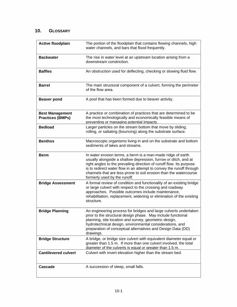
10-1
10. GLOSSARY
Active floodplain The portion of the floodplain that contains flowing channels, high water channels, and bars that flood frequently.
Backwater The rise in water level at an upstream location arising from a downstream constriction.
Baffles An obstruction used for deflecting, checking or slowing fluid flow.
Barrel The main structural component of a culvert, forming the perimeter of the flow area.
Beaver pond A pool that has been formed due to beaver activity.
Best Management Practices (BMPs)
A practice or combination of practices that are determined to be the most technologically and economically feasible means of preventing or managing potential impacts.
Bedload Larger particles on the stream bottom that move by sliding, rolling, or saltating (bouncing) along the substrate surface.
Benthos Macroscopic organisms living in and on the substrate and bottom sediments of lakes and streams.
Berm In water erosion terms, a berm is a man-made ridge of earth usually alongside a shallow depression, furrow or ditch, and at right angles to the prevailing direction of runoff flow. Its purpose is to redirect water flow in an attempt to convey the runoff through channels that are less prone to soil erosion than the watercourse formerly used by the runoff.
Bridge Assessment A formal review of condition and functionality of an existing bridge or large culvert with respect to the crossing and roadway approaches. Possible outcomes include maintenance, rehabilitation, replacement, widening or elimination of the existing structure.
Bridge Planning An engineering process for bridges and large culverts undertaken prior to the structural design phase. May include functional planning, site location and survey, geometric design, hydrotechnical design, environmental considerations, and preparation of conceptual alternatives and Design Data (DD) drawings.
Bridge Structure A bridge, or bridge size culvert with equivalent diameter equal or greater than 1.5 m. If more than one culvert involved, the total diameter of the culverts is equal or greater than 1.5 m.
Cantilevered culvert Culvert with invert elevation higher than the stream bed.
Cascade A succession of steep, small falls.
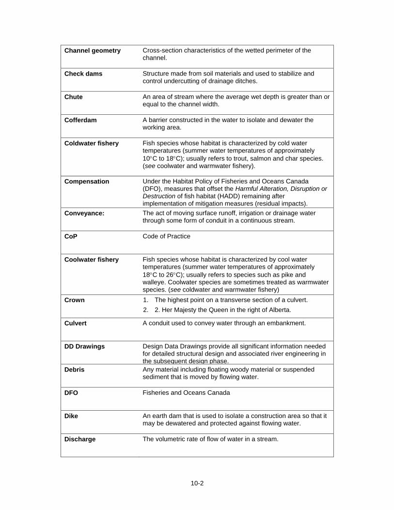
10-2
Channel geometry Cross-section characteristics of the wetted perimeter of the channel.
Check dams Structure made from soil materials and used to stabilize and control undercutting of drainage ditches.
Chute An area of stream where the average wet depth is greater than or equal to the channel width.
Cofferdam A barrier constructed in the water to isolate and dewater the working area.
Coldwater fishery Fish species whose habitat is characterized by cold water temperatures (summer water temperatures of approximately 10°C to 18°C); usually refers to trout, salmon and char species. (see coolwater and warmwater fishery).
Compensation Under the Habitat Policy of Fisheries and Oceans Canada (DFO), measures that offset the Harmful Alteration, Disruption or Destruction of fish habitat (HADD) remaining after implementation of mitigation measures (residual impacts).
Conveyance: The act of moving surface runoff, irrigation or drainage water through some form of conduit in a continuous stream.
CoP Code of Practice
Coolwater fishery Fish species whose habitat is characterized by cool water temperatures (summer water temperatures of approximately 18°C to 26°C); usually refers to species such as pike and walleye. Coolwater species are sometimes treated as warmwater species. (see coldwater and warmwater fishery)
Crown 1. The highest point on a transverse section of a culvert. 2. 2. Her Majesty the Queen in the right of Alberta.
Culvert A conduit used to convey water through an embankment.
DD Drawings Design Data Drawings provide all significant information needed for detailed structural design and associated river engineering in the subsequent design phase.
Debris Any material including floating woody material or suspended sediment that is moved by flowing water.
DFO Fisheries and Oceans Canada
Dike An earth dam that is used to isolate a construction area so that it may be dewatered and protected against flowing water.
Discharge The volumetric rate of flow of water in a stream.
10-3
Drop structure Structure used to reduce overall stream gradient.
Ecosystem A functional unit consisting of all the living organisms (plants, animals, and microbes) in a given area, and all the non-living physical and chemical factors of their environment, linked
Eddy A pool created by a current of water flowing in the opposite direction as the main current. The action digs a pool in the sediments.
Embeddedness The degree to which fine sediment is deposited between and on the surface of larger substrate particles.
Ephemeral stream A watercourse that flows during snowmelt and rainfall runoff periods only. There is generally no channel development and the stream bottom is usually vegetated.
ESCP Erosion and Sediment Control Plan
Fall Water falling over a cliff.
Fill The height of material required to raise the desired road profile above the natural ground line.
Filtering berms A temporary dam constructed with gravel or crushed rock that is used to retain and filter sediment from runoff flows.
Fish-bearing stream A stream known to support fish populations at some time of the year.
Floodplain A flat area bordering a watercourse, made up of unconsolidated river-borne material, which is periodically flooded.
Freeboard The height between the crown of the culvert and the design headwater level.
French drains Horizontal drains, backfilled with clean granular material, used to intercept seepage.
Gabion Rockfilled wire baskets used for erosion protection.
Geomorphologic Pertaining to characteristics, origin and development of landforms.
Gradient The slope of a stream defined as the vertical drop per unit of horizontal distance travelled.
Grubbing The removal and disposal of vegetation.
10-4
Guideline A recommended or acceptable course of action that is not a regulation.
Gully A small, long, narrow channel eroded by running water, particularly on hillsides and valley sides.
Gully erosion Water erosion that cuts a channel too large to be removed by normal tillage.
Habitat Those parts of the environment on which fish depend, directly or indirectly in order to carry out their life processes. Fish habitats include spawning grounds and nursery, rearing, overwintering,
HADD: Harmful alteration, disruption or destruction of fish habitat.
Headcutting Water erosion occurring at the upslope end of a gully, marked by a sharp descent from the beginning of the gully to its floor
Hydraulic gradient The slope of the water level profile along the channel, and is indicative of the energy of the flow system.
Hydrologic Pertaining to the study of the occurrence, circulation, distribution and properties of waters of the earth and its atmosphere.
Infiltration Downward movement of water through the soil surface into the ground.
Inlet: The entrance through which surface runoff enters the upstream end of a culvert, an erosion control structure or an underground pipe system.
Interception and diversion channels
Erosion control methods that consist of a shallow channel (usually a vegetated waterway) or a shallow channel combined with an earth embankment on the downhill side of the slope. The
Intergranular flow: Flow between particles of coarse grained, non-cohesive soils (e.g., sand, gravel).
Intermittent Stream: Streams that go dry during protracted rainless periods when percolation depletes all flow.
Inter-rill erosion: The uniform detachment and transportation of soil particles by water flowing in a sheet. Also known as Sheet Erosion.
Invert The floor or bottom plates of the culvert.
Lateral pool A pool that is located on the left or right side of the stream being surveyed
Mean daily flow Average measured discharge for a certain day.
Midchannel pool A pool that is located in the middle of the channel being surveyed.
10-5
Mitigation measure Action taken during the planning, design, construction, or operation of a project to avoid, prevent or minimize HADD.
Morphology The study of formation or structure.
Mulching: The addition of material (usually organic) to disturbed land surfaces to curtail erosion or retain soil moisture.
Outlet The downstream end of a culvert.
Paving: To line ditches with materials such as asphalt, granular materials, rocks, concrete and synthetic materials.
Perforated metal pipe Pipe with slots or open joints, surrounded by a filter material or blanket, used to intercept seepage.
Permanent stream A stream that flows continuously throughout the year.
Plunge Pool A pool formed when water penetrates an area quickly as it flows over an object such as a log. The force of the water digs the sediments to create a pool.
Pool An area of stream where the water velocity is slow and stream depths are relatively deep.
Project Administrator The TRANS employee who has been designated by the Project Sponsor to administer the project on a day to day basis.
Project Sponsor The TRANS employee appointed by the department to be responsible for the delivery of the project. The Project Sponsor is the department’s Senior Manger responsible for the project.
Rapids An area of stream where the water velocity is faster than a riffle.
Reclamation The process of returning a disturbed area to a condition approximating its original condition.
Revegetation Re-establishment of vegetation in disturbed areas.
Riffle An area of stream where velocity is fast and stream depths are relatively shallow causing broken water.
Right-of-way A strip of land over which a power line, railway line, road, or other linear development extends.
Riparian area The land adjacent to the normal high-water mark in a stream, river, or lake. Riparian areas typically exemplify a rich and diverse vegetation mosaic reflecting the influence of available surface water (see Floodplain).
10-6
Riprap Large boulders or angular rocks used as an armour layer.
Road Drainage Culverts
Culverts with an equivalent diameter of less than 1.5 m.
Rollback Stripping returned to disturbed areas for reclamation purposes.
Runoff That portion of rainfall or snowmelt that cannot infiltrate into the soil and so flows along the ground surface.
Runoff interception channel
A water erosion control method that consists of a ditch constructed across a slope to divert surface water.
Saturated soil Soil in which water has filled all the intergranular spaces in a soil profile.
Scarify The process of loosening or stirring the soil to shallow depths without turning it over.
Scour The removal of sediment from a watercourse substrate by flowing water.
Sediment Fragmentary material, originating from the disintegration of rocks, that is suspended, transported or deposited by wind, water or ice.
Sedimentation The process of subsidence and deposition of suspended matter carried in water by gravity; usually the result of the reduction of water velocity below the point at which it can transport the material in suspended form; sometimes referred to as siltation.
Sediment carrying capacity
The maximum amount of material held in suspension by a stream.
Sheet Erosion see Inter-rill erosion.
Siltation The deposition of fine-textured sediment
Siltation ponds Temporary water retention ponds used to trap and retain sediments.
Soil 1. The unconsolidated mineral and organic material on the immediate surface of the earth that serves as a natural medium for the growth of land plants. It is also called the topsoil.
2. The unconsolidated matter on the surface of the earth that lies on top of the bedrock. It is also called the regolith.
Spring A place where water flows from a rock or soil onto the land or into a body of water.
10-7
Stream A watercourse formed when water flows between continuous definable banks.
Streambank The rising ground bordering a stream channel.
Streambed The bottom of a stream below the usual water surface.
Stream channel The non-vegetated area of a watercourse beneath the height of annual peak flow.
Stream confinement Where valley walls laterally constrain the natural meander pattern of a stream.
Stream pattern The planform shape of the stream (e.g., meandering, braided, etc.)
Stripping Removal of topsoil and fine debris above mineral soil.
Subgrade Soil prepared and compacted to support a road.
Substrate The bottom of a waterbody on which organisms live (e.g., streambed materials).
Suspended solids Sediment that is transported via suspension through the buoyancy and drag forces of flowing water and that stays in suspension for an appreciable period of time (mainly clays and silts). Also known as suspended sediment.
Suspended sediment see Suspended solids.
Tailwater depth The depth of flow downstream of the culvert.
Turbulent flow Flow regime where fluid motion is disorderly and velocities fluctuate.
Velocity The distance travelled per unit of time.
Warmwater fishery Fish species whose habitat is characterized by warm water temperatures (summer water temperatures may exceed 26°C); usually refers to species such as bass and sunfish. (see Coldwater fishery and Coolwater fishery).
Wash load That portion of the suspended load which comprises the finest particle sizes that originate in the watershed and which are not normally found in streambed deposits. Particles comprising the wash load are in near-permanent suspension.
10-8
Waterbar A shallow ditch excavated across a road at an angle to prevent excess surface flow down the road surface and subsequent erosion of road surface material.
Waterbody A natural or artificial source of surface water including lakes, sloughs and wetlands.
Watercourse Any channel carrying water, either continuously or intermittently.
Water erosion The process by which solid particles are detached and transported by water.
Watershed An area of land that collects and discharges water into a single creek or river through a series of smaller tributaries.
Water velocity The distance travelled by water per unit of time.

CHAPTER 11
11-i
TABLE OF CONTENTS
11. References....................................................................................................11-1

11-ii
Page left blank intentionally
11-1
11. References
Alberta Sustainable Resource Development and Alberta Conservation Association. 2006. Status of the westslope cutthroat trout (Oncorhynchus clarki lewisi) in Alberta. Alberta Sustainable Resource Development, Wildlife Status Report No. 61, Edmonton, AB. 34 pp.
Alberta Transportation. 2006. Best Practice Guideline #9 – Rock Protection for Stream Related Infrastructure.
Alberta Transportation, in preparation (2009). Fish Passage Through Culverts.
Barton, B.A. 1977. Short-term effects of highway construction on the limnology of a small stream in southern Ontario. Freshwater Biology 7 99-108.
Blench, T. 1986. Mechanics of Plains Rivers: A Regime Theory Treatment of Canals and Rivers for Engineers and Environmentalists, University of Alberta Printing Services, Edmonton, 109 p.
Bowlby, J.N., R.B.Biette, D.P.Dodge and J.G. Imhoff. 1987. Long-term impacts of highway construction on Mill Creek, Ontario. In C.H. Oliver, editor. Ontario Fisheries Technical Report Series 24. Ministry of Natural Resources.
Committee on the Status of Endangered Wildlife in Canada. 2001. COSEWIC assessment and status report on the western silvery minnow Hybognathus argyritis in Canada. Committee on the Status of Endangered Wildlife in Canada. Ottawa. vii + 14 pp.
Committee on the Status of Endangered Wildlife in Canada. 2005. COSEWIC assessment and status report on the “eastslope” sculpin (St. Mary and Milk River population) Cottus sp. in Canada. Committee on the Status of Endangered Wildlife in Canada. Ottawa. vi + 30 pp.
DFO. 2007. Practitioners Guide to Habitat Compensation. Canada Department of Fisheries and Oceans.
Eaglin, G.S., and W.A. Hubert. 1993. Effects of logging and roads on substrate and trout in streams of the Medicine Bow National Forest, Wyoming. North American Journal of Fisheries Management 13:844-846.
Fraley, J.J. 1979. Effects of Elevated Stream Temperatures Below a Shallow Reservoir on a Cold Water Macroinvertebrate Fauna, in The Ecology of Regulated Streams, J.V. Ward and J.A. Stanford [ed.], Plenum Publishing Corp., New York, New York.
Hawkins, C.P. and 10 other authors. 1993. A hierarchical approach to classifying stream habitat features. Fisheries 18 (June): 3-12.
IECA. 1998. Erosion and Sediment Control Practices for Construction Activities at Water Crossings, A Short Course Sponsored by the International Erosion Control Association.
King, D.L. and R.C. Ball. 1964. The influence of highway construction on a stream. Michigan State University, Agricultural Experiment Station, Research Report 19, East Lansing.
Kondolf, G.M. 1997. Application of the pebble count: Notes on purpose, method and variants. Journal of the American Water Resources Association 33: pp 79-87.
Langhorne, A. L., M. Neufeld, G. Hoar, V. Bourhis, D. A. Fernet and C. K. Minns. 2001. Life history characteristics of freshwater fishes occurring in Manitoba, Saskatchewan
11-2
and Alberta, with major emphasis on lake habitat requirements. Can. MS Rpt. Fish. Aquat. Sci. 2579: xii + 170 pp.
Leopold, L.B., M.G. Wolman and J.P. Miller. 1964. Fluvial processes in geomorphology. Freeman, San Francisco, 522 p.
McRae, G. and C.J. Edwards. 1992. Thermal Impacts of Beaver Impoundments in Wisconsin Headwater Streams, Proceedings of the 54th Midwest Fish & Wildlife Conference, Toronto, Ontario, 400 p.
Nelson, J. S. and M. J. Paetz. 1992. The Fishes of Alberta. U. of Alberta Press, Edmonton and the U. of Calgary Press, Calgary.
Newbury, R.W. and M.N. Gaboury. 1993. Stream Analysis and Fish Habitat Design: A Field Manual. Newbury Hydraulics Ltd., Gibsons, B.C.
OMNR. 1994. Natural Channel Systems: An Approach to Management and Design, Ontario Ministry of Natural Resources, Toronto, 103 p.
Overton, C.K., S.P. Wollrab, B.C. Roberts and M.A. Radko. 1997. R1/R4 (Northern/ Intermountain Regions) Fish and Fish Habitat Standard Inventory Procedures Handbook, General Technical Report INT-6TR-346, United States Department of Agriculture, Forest Service, Intermountain Research Station, Ogden, Utah, 73 p.
R.L. & L. Environmental Services Ltd. 1994. A general fish and riverine habitat inventory, Athabasca River, April to May 1992. NRBS Project Report No. 32, Edmonton, Alberta. 74 p + appendices. Rajaratnam, N., and C. Katopodis. 1990. Hydraulics of Culvert Fishways III: Weir Baffle Culvert Fishways, Canadian J. Civil Engineering, 17(4):558-568.
Reed, J. R. 1977. Stream community response to road construction sediments. Virginia Water Resources Center Bulletin 97. 90 p.
Roberge, M., J. M. B. Hume, C. K. M.inns and T. Slaney. 2002. Life history characteristics of freshwater fishes occurring in British Columbia and the Yukon, with major emphasis on stream habitat characteristics. Can. Manuscr. Rep. Fish. Aquat. Sci. 2611: xiv + 248 pp.
Rosgen, D. 1996. Applied River Morphology, Wildland Hydrology, Pagosa Springs, Colorado.
Scott, W.B. and E.J. Crossman. 1973. Freshwater Fishes of Canada, Fisheries Research Board of Canada Bulletin 184, 966 p.
Taylor, B.R. and J.C. Roff. 1986. Long-term effects of highway construction on the ecology of a southern Ontario stream. Environmental Pollution (Series A) 40:317-344.
Terzi, R.A. 1981. Hydrometric field manual measurement of streamflow. Environment Canada, Inland Waters Directorate, Water Resources Branch, Ottawa. 37 pp.
APPENDIX I
FISH HABITAT MITIGATION
TECHNIQUE FACTSHEETS

Page left blank intentionally
Appendix I-I
I. Fish Habitat Mitigation Technique Factsheets
The following Factsheets provide representative examples of measures to mitigate impacts to fish habitat during the construction of stream crossings. Additional mitigation measures for erosion and sediment effects are in “Design Guidelines for Erosion and Sediment Control for Highways” (http://www.transportation.alberta.ca/1812.htm)
Each of the following factsheets provides a brief description of the measure, a review of conditions where it may be applicable, design provisions, implementation procedures and maintenance requirements. Drawings and photographs are provided where applicable. The mitigation techniques presented in the Factsheets are standard non-engineered measures. A professional engineer should review their application to specific situations.
1) CONSTRUCTION PRACTICES
• M1: Best Management Practices
• M2: Blasting Guidelines
2) INSTREAM SEDIMENT CONTROL
• M3: Cofferdams
• M4: Instream Silt Barriers
• M5: Sensitive Area Isolation
3) EROSION CONTROL
• M6: Groynes and Spurs
• M7: Vegetated Waterways
• M8: Native Material Bank Revetment
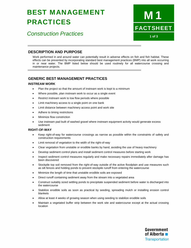
FACTSHEET
M11 of 3
BEST MANAGEMENT PRACTICES
Construction Practices
DESCRIPTION AND PURPOSE Work performed in and around water can potentially result in adverse effects on fish and fish habitat. These effects can be prevented by incorporating standard best management practices (BMP) into all work occurring in or near water. The BMP listed below should be used routinely for all watercourse crossing and maintenance projects.
GENERIC BEST MANAGEMENT PRACTICES INSTREAM WORK
• Plan the project so that the amount of instream work is kept to a minimum
• Where possible, plan instream work to occur as a single event
• Restrict instream work to low flow periods where possible
• Limit machinery access to a single point on one bank
• Limit distance between machinery access point and work site
• Adhere to timing restrictions
• Minimize flow constriction
• Use instream pad built of washed gravel where instream equipment activity would generate excess sediment
RIGHT-OF-WAY • Keep right-of-way for watercourse crossings as narrow as possible within the constraints of safety and
construction requirements
• Limit removal of vegetation to the width of the right-of-way
• Clear vegetation from unstable or erodible banks by hand, avoiding the use of heavy machinery
• Develop sediment control plans and install sediment control measures before starting work
• Inspect sediment control measures regularly and make necessary repairs immediately after damage has been discovered
• Stockpile top soil removed from the right-of-way outside of the active floodplain and use measures such as silt fences and holding ponds to prevent stockpile runoff from entering the watercourse
• Minimize the length of time that unstable erodible soils are exposed
• Direct runoff containing sediment away from the stream into a vegetated area
• Construct suitably sized settling ponds to precipitate suspended sediment before water is discharged into the watercourse
• Stabilize erodible soils as soon as practical by seeding, spreading mulch or installing erosion control blankets
• Allow at least 4 weeks of growing season when using seeding to stabilize erodible soils
• Maintain a vegetated buffer strip between the work site and watercourse except at the actual crossing location
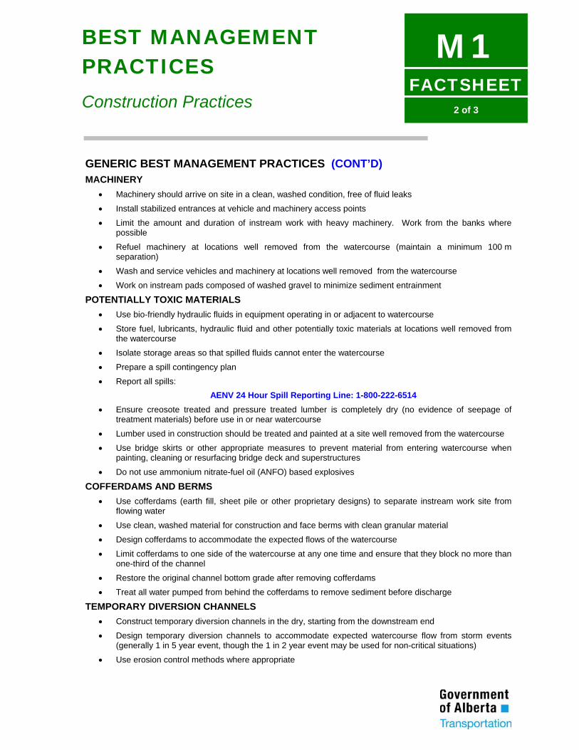
FACTSHEET
M12 of 3
BEST MANAGEMENT PRACTICES
Construction Practices
GENERIC BEST MANAGEMENT PRACTICES (CONT’D) MACHINERY
• Machinery should arrive on site in a clean, washed condition, free of fluid leaks
• Install stabilized entrances at vehicle and machinery access points
• Limit the amount and duration of instream work with heavy machinery. Work from the banks where possible
• Refuel machinery at locations well removed from the watercourse (maintain a minimum 100 m separation)
• Wash and service vehicles and machinery at locations well removed from the watercourse
• Work on instream pads composed of washed gravel to minimize sediment entrainment
POTENTIALLY TOXIC MATERIALS • Use bio-friendly hydraulic fluids in equipment operating in or adjacent to watercourse
• Store fuel, lubricants, hydraulic fluid and other potentially toxic materials at locations well removed from the watercourse
• Isolate storage areas so that spilled fluids cannot enter the watercourse
• Prepare a spill contingency plan
• Report all spills: AENV 24 Hour Spill Reporting Line: 1-800-222-6514
• Ensure creosote treated and pressure treated lumber is completely dry (no evidence of seepage of treatment materials) before use in or near watercourse
• Lumber used in construction should be treated and painted at a site well removed from the watercourse
• Use bridge skirts or other appropriate measures to prevent material from entering watercourse when painting, cleaning or resurfacing bridge deck and superstructures
• Do not use ammonium nitrate-fuel oil (ANFO) based explosives
COFFERDAMS AND BERMS • Use cofferdams (earth fill, sheet pile or other proprietary designs) to separate instream work site from
flowing water
• Use clean, washed material for construction and face berms with clean granular material
• Design cofferdams to accommodate the expected flows of the watercourse
• Limit cofferdams to one side of the watercourse at any one time and ensure that they block no more than one-third of the channel
• Restore the original channel bottom grade after removing cofferdams
• Treat all water pumped from behind the cofferdams to remove sediment before discharge
TEMPORARY DIVERSION CHANNELS • Construct temporary diversion channels in the dry, starting from the downstream end
• Design temporary diversion channels to accommodate expected watercourse flow from storm events (generally 1 in 5 year event, though the 1 in 2 year event may be used for non-critical situations)
• Use erosion control methods where appropriate
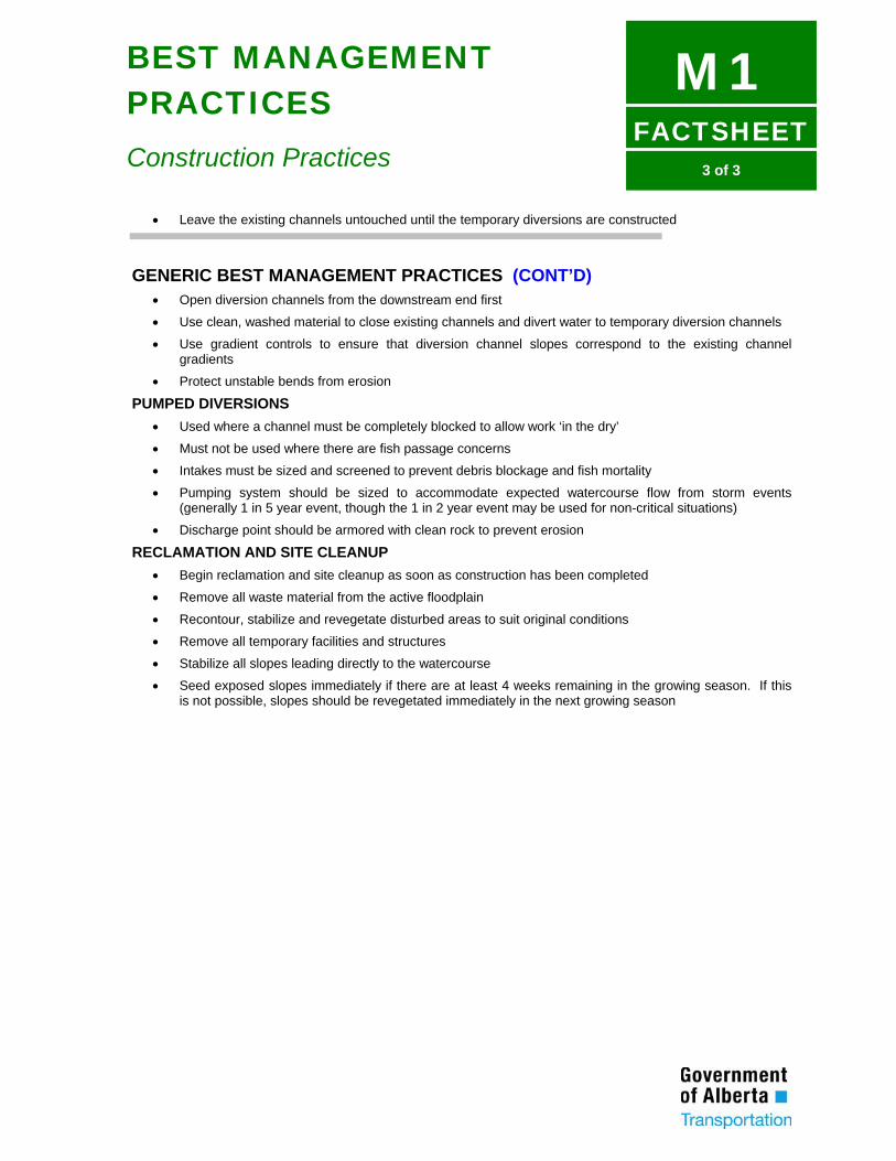
FACTSHEET
M13 of 3
BEST MANAGEMENT PRACTICES
Construction Practices
• Leave the existing channels untouched until the temporary diversions are constructed
GENERIC BEST MANAGEMENT PRACTICES (CONT’D) • Open diversion channels from the downstream end first
• Use clean, washed material to close existing channels and divert water to temporary diversion channels
• Use gradient controls to ensure that diversion channel slopes correspond to the existing channel gradients
• Protect unstable bends from erosion
PUMPED DIVERSIONS • Used where a channel must be completely blocked to allow work ‘in the dry’
• Must not be used where there are fish passage concerns
• Intakes must be sized and screened to prevent debris blockage and fish mortality
• Pumping system should be sized to accommodate expected watercourse flow from storm events (generally 1 in 5 year event, though the 1 in 2 year event may be used for non-critical situations)
• Discharge point should be armored with clean rock to prevent erosion
RECLAMATION AND SITE CLEANUP • Begin reclamation and site cleanup as soon as construction has been completed
• Remove all waste material from the active floodplain
• Recontour, stabilize and revegetate disturbed areas to suit original conditions
• Remove all temporary facilities and structures
• Stabilize all slopes leading directly to the watercourse
• Seed exposed slopes immediately if there are at least 4 weeks remaining in the growing season. If this is not possible, slopes should be revegetated immediately in the next growing season

Appendix I-II
Page left blank intentionally
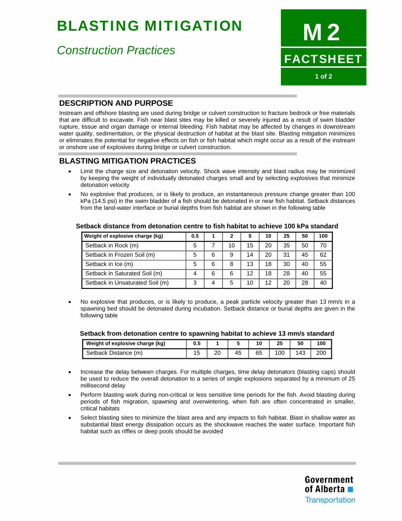
FACTSHEET
M21 of 2
BLASTING MITIGATION
Construction Practices
DESCRIPTION AND PURPOSE Instream and offshore blasting are used during bridge or culvert construction to fracture bedrock or free materials that are difficult to excavate. Fish near blast sites may be killed or severely injured as a result of swim bladder rupture, tissue and organ damage or internal bleeding. Fish habitat may be affected by changes in downstream water quality, sedimentation, or the physical destruction of habitat at the blast site. Blasting mitigation minimizes or eliminates the potential for negative effects on fish or fish habitat which might occur as a result of the instream or onshore use of explosives during bridge or culvert construction.
BLASTING MITIGATION PRACTICES • Limit the charge size and detonation velocity. Shock wave intensity and blast radius may be minimized
by keeping the weight of individually detonated charges small and by selecting explosives that minimize detonation velocity
• No explosive that produces, or is likely to produce, an instantaneous pressure change greater than 100 kPa (14.5 psi) in the swim bladder of a fish should be detonated in or near fish habitat. Setback distances from the land-water interface or burial depths from fish habitat are shown in the following table
Setback distance from detonation centre to fish habitat to achieve 100 kPa standard
Weight of explosive charge (kg) 0.5 1 2 5 10 25 50 100
Setback in Rock (m) 5 7 10 15 20 35 50 70 Setback in Frozen Soil (m) 5 6 9 14 20 31 45 62 Setback in Ice (m) 5 6 8 13 18 30 40 55 Setback in Saturated Soil (m) 4 6 6 12 18 28 40 55 Setback in Unsaturated Soil (m) 3 4 5 10 12 20 28 40
• No explosive that produces, or is likely to produce, a peak particle velocity greater than 13 mm/s in a
spawning bed should be detonated during incubation. Setback distance or burial depths are given in the following table
Setback from detonation centre to spawning habitat to achieve 13 mm/s standard
Weight of explosive charge (kg) 0.5 1 5 10 25 50 100
Setback Distance (m) 15 20 45 65 100 143 200
• Increase the delay between charges. For multiple charges, time delay detonators (blasting caps) should be used to reduce the overall detonation to a series of single explosions separated by a minimum of 25 millisecond delay
• Perform blasting work during non-critical or less sensitive time periods for the fish. Avoid blasting during periods of fish migration, spawning and overwintering, when fish are often concentrated in smaller, critical habitats
• Select blasting sites to minimize the blast area and any impacts to fish habitat. Blast in shallow water as substantial blast energy dissipation occurs as the shockwave reaches the water surface. Important fish habitat such as riffles or deep pools should be avoided
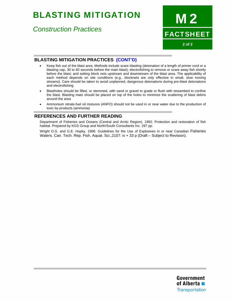
FACTSHEET
M22 of 2
BLASTING MITIGATION
Construction Practices
BLASTING MITIGATION PRACTICES (CONT’D) • Keep fish out of the blast area. Methods include scare blasting (detonation of a length of primer cord or a
blasting cap, 30 to 60 seconds before the main blast); electrofishing to remove or scare away fish shortly before the blast; and setting block nets upstream and downstream of the blast area. The applicability of each method depends on site conditions (e.g., blocknets are only effective in small, slow moving streams). Care should be taken to avoid unplanned, dangerous detonations during pre-blast detonations and electrofishing
• Blastholes should be filled, or stemmed, with sand or gravel to grade or flush with streambed to confine the blast. Blasting mats should be placed on top of the holes to minimize the scattering of blast debris around the area
• Ammonium nitrate-fuel oil mixtures (ANFO) should not be used in or near water due to the production of toxic by-products (ammonia)
REFERENCES AND FURTHER READING Department of Fisheries and Oceans (Central and Arctic Region). 1992. Protection and restoration of fish habitat. Prepared by KGS Group and North/South Consultants Inc. 297 pp. Wright D.G. and G.E. Hopky, 1998. Guidelines for the Use of Explosives in or near Canadian Fisheries Waters. Can. Tech. Rep. Fish. Aquat. Sci.,2107: iv + 33 p (Draft – Subject to Revision).
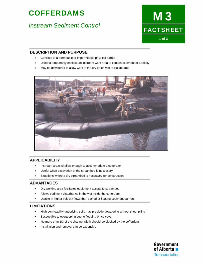
FACTSHEET
M31 of 3
COFFERDAMS
Instream Sediment Control
DESCRIPTION AND PURPOSE • Consists of a permeable or impermeable physical barrier
• Used to temporarily enclose an instream work area to contain sediment or turbidity
• May be dewatered to allow work in the dry or left wet to isolate area
APPLICABILITY • Instream areas shallow enough to accommodate a cofferdam
• Useful when excavation of the streambed is necessary
• Situations where a dry streambed is necessary for construction
ADVANTAGES • Dry working area facilitates equipment access to streambed
• Allows sediment disturbance in the wet inside the cofferdam
• Usable in higher velocity flows than staked or floating sediment barriers
LIMITATIONS • High permeability underlying soils may preclude dewatering without sheet piling
• Susceptible to overtopping due to flooding or ice cover
• No more than 1/3 of the channel width should be blocked by the cofferdam
• Installation and removal can be expensive
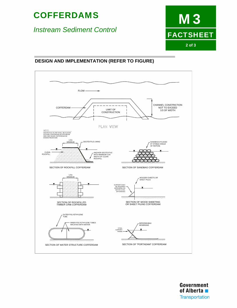
FACTSHEET
M32 of 3
COFFERDAMS
Instream Sediment Control
DESIGN AND IMPLEMENTATION (REFER TO FIGURE)
LIMIT OFCONSTRUCTION
CHANNEL CONSTRICTIONNOT TO EXCEED
1/3 OF WIDTH
FLOW
COFFERDAM
1.5mMINIMUM
ANCHOR GEOTEXTILEWITH MINIMUM 0.3mWIDTH OF CLEAN
GEOTEXTILE LINING
CLEANROCKFILL
GEOTEXTILE FILTER SHALL BE PLACEDOUTSIDE COFFERDAM ON UPSTREAMSIDE AND INSIDE COFFERDAM ONDOWNSTREAM SIDE
ROCKFILL
OF REPOSEAT STABLE ANGLESANDBAGS PLACED
WOODEN SHEETS ORSHEET PILES
SUPPORTS MAYBE REQUIRED
DEPENDING ONWATER LEVEL
DIFFERENCE
1.5mMINIMUM
TUBEOUTER POLYETHYLENE
INNER POLYETHYLENE TUBESINFLATED WITH WATER
SUPPORTSTEEL
MEMBRANEIMPERMEABLE
FRAME
SECTION OF ROCKFILL COFFERDAM SECTION OF SANDBAG COFFERDAM
SECTION OF WOOD SHEETINGSECTION OF ROCKFILLED
SECTION OF "PORTADAM" COFFERDAMSECTION OF WATER STRUCTURE COFFERDAM
TIMBER CRIB COFFERDAM OR SHEET PILING COFFERDAM
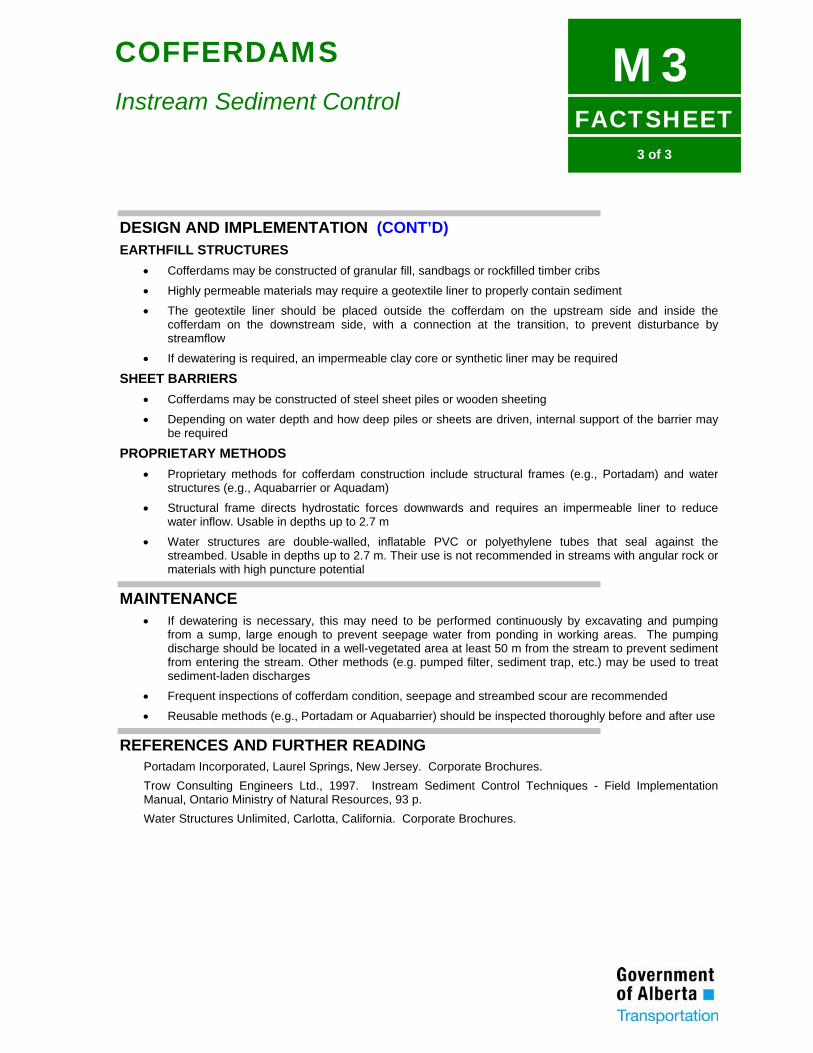
FACTSHEET
M33 of 3
COFFERDAMS
Instream Sediment Control
DESIGN AND IMPLEMENTATION (CONT’D) EARTHFILL STRUCTURES
• Cofferdams may be constructed of granular fill, sandbags or rockfilled timber cribs
• Highly permeable materials may require a geotextile liner to properly contain sediment
• The geotextile liner should be placed outside the cofferdam on the upstream side and inside the cofferdam on the downstream side, with a connection at the transition, to prevent disturbance by streamflow
• If dewatering is required, an impermeable clay core or synthetic liner may be required
SHEET BARRIERS • Cofferdams may be constructed of steel sheet piles or wooden sheeting
• Depending on water depth and how deep piles or sheets are driven, internal support of the barrier may be required
PROPRIETARY METHODS • Proprietary methods for cofferdam construction include structural frames (e.g., Portadam) and water
structures (e.g., Aquabarrier or Aquadam)
• Structural frame directs hydrostatic forces downwards and requires an impermeable liner to reduce water inflow. Usable in depths up to 2.7 m
• Water structures are double-walled, inflatable PVC or polyethylene tubes that seal against the streambed. Usable in depths up to 2.7 m. Their use is not recommended in streams with angular rock or materials with high puncture potential
MAINTENANCE • If dewatering is necessary, this may need to be performed continuously by excavating and pumping
from a sump, large enough to prevent seepage water from ponding in working areas. The pumping discharge should be located in a well-vegetated area at least 50 m from the stream to prevent sediment from entering the stream. Other methods (e.g. pumped filter, sediment trap, etc.) may be used to treat sediment-laden discharges
• Frequent inspections of cofferdam condition, seepage and streambed scour are recommended
• Reusable methods (e.g., Portadam or Aquabarrier) should be inspected thoroughly before and after use
REFERENCES AND FURTHER READING Portadam Incorporated, Laurel Springs, New Jersey. Corporate Brochures. Trow Consulting Engineers Ltd., 1997. Instream Sediment Control Techniques - Field Implementation Manual, Ontario Ministry of Natural Resources, 93 p. Water Structures Unlimited, Carlotta, California. Corporate Brochures.
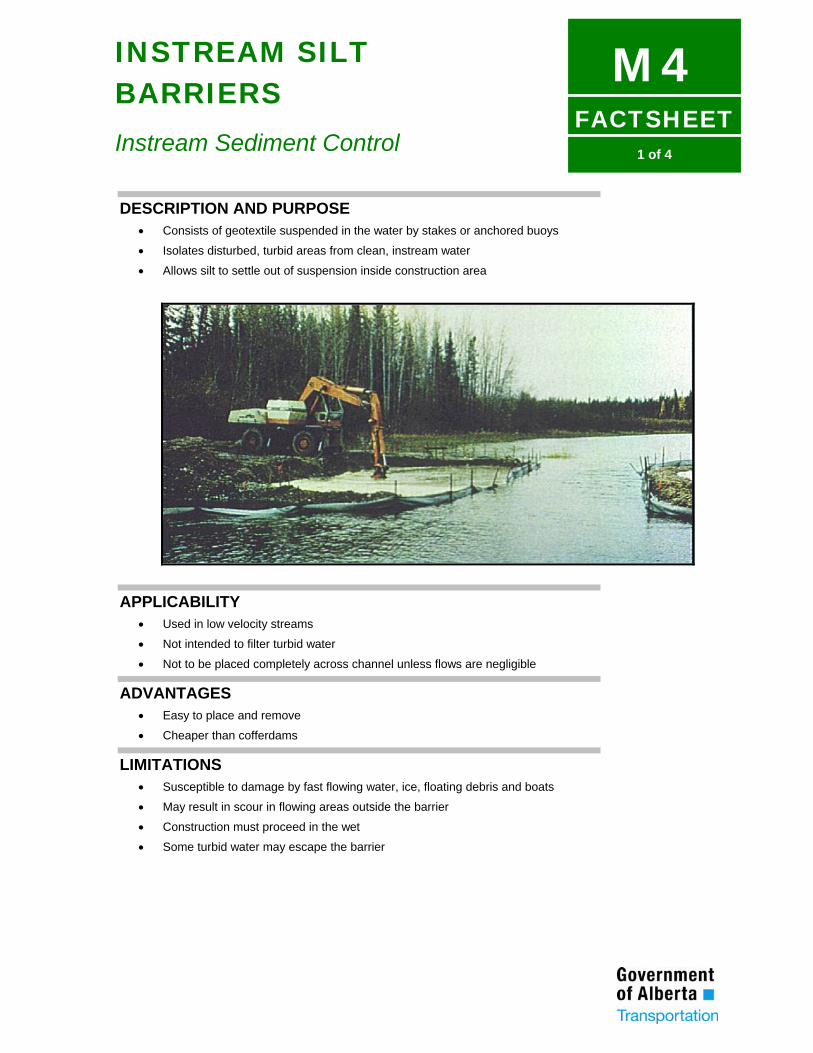
FACTSHEET
M41 of 4
INSTREAM SILT BARRIERS
Instream Sediment Control
DESCRIPTION AND PURPOSE • Consists of geotextile suspended in the water by stakes or anchored buoys
• Isolates disturbed, turbid areas from clean, instream water
• Allows silt to settle out of suspension inside construction area
APPLICABILITY • Used in low velocity streams
• Not intended to filter turbid water
• Not to be placed completely across channel unless flows are negligible
ADVANTAGES • Easy to place and remove
• Cheaper than cofferdams
LIMITATIONS • Susceptible to damage by fast flowing water, ice, floating debris and boats
• May result in scour in flowing areas outside the barrier
• Construction must proceed in the wet
• Some turbid water may escape the barrier
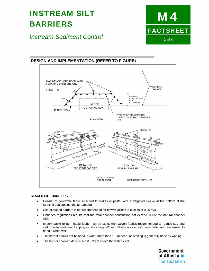
FACTSHEET
M42 of 4
INSTREAM SILT BARRIERS
Instream Sediment Control
DESIGN AND IMPLEMENTATION (REFER TO FIGURE)
SCHEMATIC ONLYNOT TO SCALE REFERENCE: TROW, 1997
DETAIL OFFLOATING BARRIER
DETAIL OFSTAKED BARRIER
FLOWSTREAM
CHANNELCONSTRICTIONNOT TOEXCEED 1/3
LIMIT OFCONSTRUCTION
MARINE ANCHORS USED WITHFLOATING BARRIERS ONLY
BANKS
STAKES OR FENCEPOSTSUSED WITH STAKED BARRIERSONLY
45 OR LESS
PLAN VIEW
load line
float flotation pocket
stakes/postsbuoy
STAKED SILT BARRIERS
• Consist of geotextile fabric attached to stakes or posts, with a weighted sleeve at the bottom of the fabric to seal against the streambed
• Use of staked barriers is not recommended for flow velocities in excess of 0.25 m/s
• Fisheries regulations require that the total channel constriction not exceed 1/3 of the natural channel width
• Impermeable or permeable fabric may be used, with woven fabrics recommended to reduce sag and sink due to sediment trapping or stretching. Woven fabrics also absorb less water and are easier to handle when wet
• The barrier should not be used in water more than 1.2 m deep, as staking is generally done by wading
• The barrier should extend at least 0.30 m above the water level
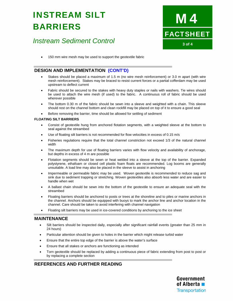
FACTSHEET
M43 of 4
INSTREAM SILT BARRIERS
Instream Sediment Control
• 150 mm wire mesh may be used to support the geotextile fabric
DESIGN AND IMPLEMENTATION (CONT’D) • Stakes should be placed a maximum of 1.5 m (no wire mesh reinforcement) or 3.0 m apart (with wire
mesh reinforcement). Stakes may be braced to resist current forces or a partial cofferdam may be used upstream to deflect current
• Fabric should be secured to the stakes with heavy duty staples or nails with washers. Tie wires should be used to attach the wire mesh (if used) to the fabric. A continuous roll of fabric should be used wherever possible
• The bottom 0.30 m of the fabric should be sewn into a sleeve and weighted with a chain. This sleeve should rest on the channel bottom and clean rockfill may be placed on top of it to ensure a good seal
• Before removing the barrier, time should be allowed for settling of sediment FLOATING SILT BARRIERS
• Consist of geotextile hung from anchored flotation segments, with a weighted sleeve at the bottom to seal against the streambed
• Use of floating silt barriers is not recommended for flow velocities in excess of 0.15 m/s
• Fisheries regulations require that the total channel constriction not exceed 1/3 of the natural channel width
• The maximum depth for use of floating barriers varies with flow velocity and availability of anchorage, but depths in excess of 4 m are possible
• Flotation segments should be sewn or heat welded into a sleeve at the top of the barrier. Expanded polystyrene, ethafoam or closed cell plastic foam floats are recommended. Log booms are generally unsuitable. A load line may also be placed in the sleeve to assist in anchoring
• Impermeable or permeable fabric may be used. Woven geotextile is recommended to reduce sag and sink due to sediment trapping or stretching. Woven geotextiles also absorb less water and are easier to handle when wet
• A ballast chain should be sewn into the bottom of the geotextile to ensure an adequate seal with the streambed
• Floating barriers should be anchored to posts or trees at the shoreline and to piles or marine anchors in the channel. Anchors should be equipped with buoys to mark the anchor line and anchor location in the channel. Care should be taken to avoid interfering with channel navigation
• Floating silt barriers may be used in ice-covered conditions by anchoring to the ice sheet
MAINTENANCE • Silt barriers should be inspected daily, especially after significant rainfall events (greater than 25 mm in
24 hours)
• Particular attention should be given to holes in the barrier which might release turbid water
• Ensure that the entire top edge of the barrier is above the water’s surface
• Ensure that all stakes or anchors are functioning as intended
• Torn geotextile should be replaced by adding a continuous piece of fabric extending from post to post or by replacing a complete section
REFERENCES AND FURTHER READING

FACTSHEET
M44 of 4
INSTREAM SILT BARRIERS
Instream Sediment Control
Trow Consulting Engineers Ltd., 1997. Instream Sediment Control Techniques - Field Implementation Manual, Ontario Ministry of Natural Resources, 93 p.
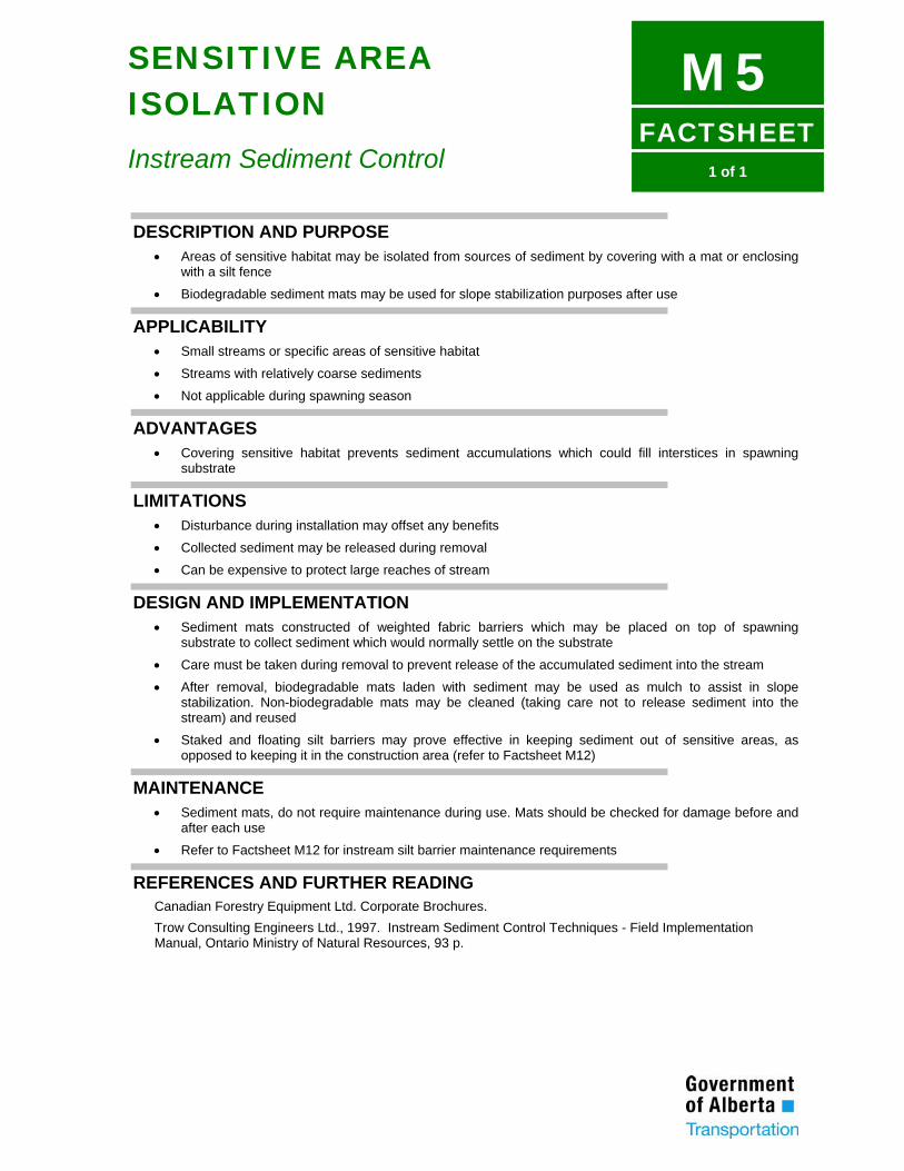
FACTSHEET
M51 of 1
SENSITIVE AREA ISOLATION
Instream Sediment Control
DESCRIPTION AND PURPOSE • Areas of sensitive habitat may be isolated from sources of sediment by covering with a mat or enclosing
with a silt fence
• Biodegradable sediment mats may be used for slope stabilization purposes after use
APPLICABILITY • Small streams or specific areas of sensitive habitat
• Streams with relatively coarse sediments
• Not applicable during spawning season
ADVANTAGES • Covering sensitive habitat prevents sediment accumulations which could fill interstices in spawning
substrate
LIMITATIONS • Disturbance during installation may offset any benefits
• Collected sediment may be released during removal
• Can be expensive to protect large reaches of stream
DESIGN AND IMPLEMENTATION • Sediment mats constructed of weighted fabric barriers which may be placed on top of spawning
substrate to collect sediment which would normally settle on the substrate
• Care must be taken during removal to prevent release of the accumulated sediment into the stream
• After removal, biodegradable mats laden with sediment may be used as mulch to assist in slope stabilization. Non-biodegradable mats may be cleaned (taking care not to release sediment into the stream) and reused
• Staked and floating silt barriers may prove effective in keeping sediment out of sensitive areas, as opposed to keeping it in the construction area (refer to Factsheet M12)
MAINTENANCE • Sediment mats, do not require maintenance during use. Mats should be checked for damage before and
after each use
• Refer to Factsheet M12 for instream silt barrier maintenance requirements
REFERENCES AND FURTHER READING Canadian Forestry Equipment Ltd. Corporate Brochures. Trow Consulting Engineers Ltd., 1997. Instream Sediment Control Techniques - Field Implementation Manual, Ontario Ministry of Natural Resources, 93 p.

FACTSHEET
M61 of 3
GROYNES AND SPURS
Erosion Control
DESCRIPTION AND PURPOSE • Projects into the stream for a short distance to deflect flowing water away from the streambank
• Redirects the flow towards the centre of the channel and protects the streambank against erosion
• Encourages deposition of sediment and growth of vegetation against the streambank between spurs or groynes
APPLICABILITY • Used to protect eroding banks on the outside of bends of a channel
• Alternative to bank armour (riprap or gabions) when it is desirable to leave bank areas undisturbed
ADVANTAGES • Less impact on the streambank than bank armour
• May increase fish habitat diversity through enhancement of vegetation and introduction of refugia
LIMITATIONS • Increased flow velocities may cause scour at the tip of the spur or groyne
• May require instream work unless installed at extreme low water
• May present a hazard to navigation, especially for shallow structures
• May be difficult to construct in channels with steep channel sideslopes
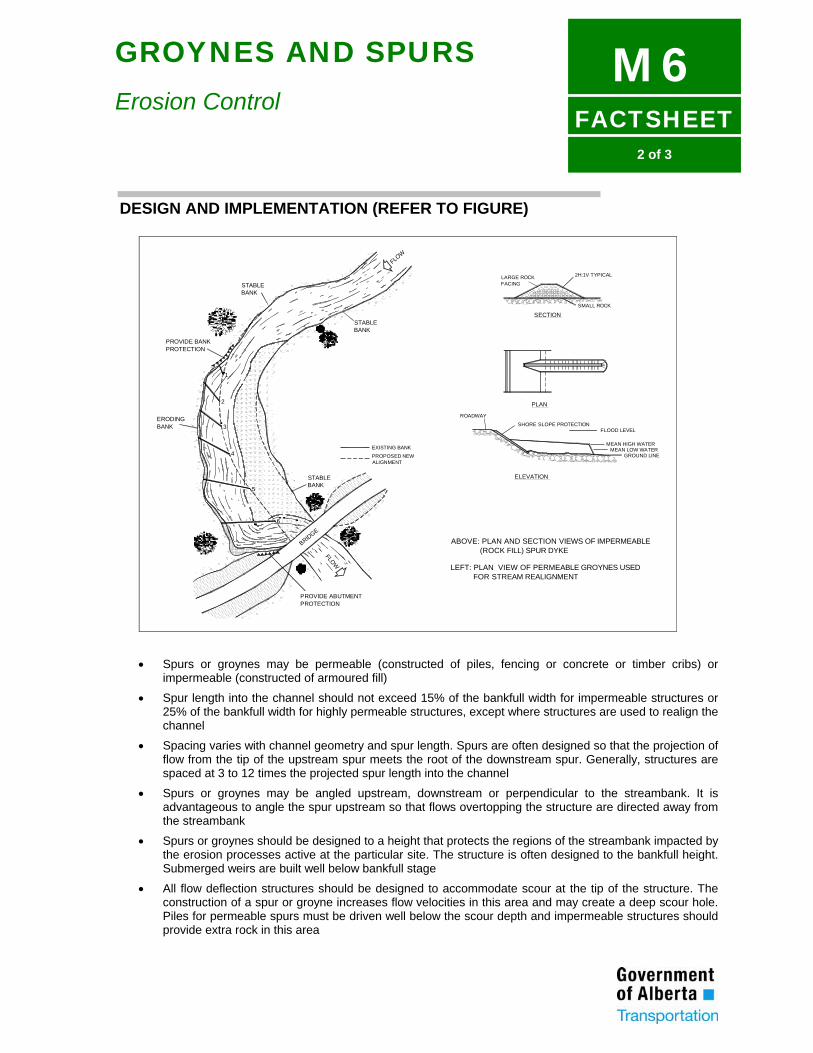
FACTSHEET
M62 of 3
GROYNES AND SPURS
Erosion Control
DESIGN AND IMPLEMENTATION (REFER TO FIGURE)
STABLEBANK
STABLEBANK
PROVIDE BANKPROTECTION
ERODINGBANK
STABLEBANK
PROVIDE ABUTMENTPROTECTION
BRIDGE
FLOW
FLOW
EXISTING BANKPROPOSED NEWALIGNMENT
1
2
3
4
5
6
2H:1V TYPICALLARGE ROCKFACING
SECTIONSMALL ROCK
ROADWAY
PLAN
SHORE SLOPE PROTECTION
ELEVATION
FLOOD LEVEL
MEAN HIGH WATERMEAN LOW WATER
GROUND LINE
ABOVE: PLAN AND SECTION VIEWS OF IMPERMEABLE (ROCK FILL) SPUR DYKE
LEFT: PLAN VIEW OF PERMEABLE GROYNES USED FOR STREAM REALIGNMENT
• Spurs or groynes may be permeable (constructed of piles, fencing or concrete or timber cribs) or impermeable (constructed of armoured fill)
• Spur length into the channel should not exceed 15% of the bankfull width for impermeable structures or 25% of the bankfull width for highly permeable structures, except where structures are used to realign the channel
• Spacing varies with channel geometry and spur length. Spurs are often designed so that the projection of flow from the tip of the upstream spur meets the root of the downstream spur. Generally, structures are spaced at 3 to 12 times the projected spur length into the channel
• Spurs or groynes may be angled upstream, downstream or perpendicular to the streambank. It is advantageous to angle the spur upstream so that flows overtopping the structure are directed away from the streambank
• Spurs or groynes should be designed to a height that protects the regions of the streambank impacted by the erosion processes active at the particular site. The structure is often designed to the bankfull height. Submerged weirs are built well below bankfull stage
• All flow deflection structures should be designed to accommodate scour at the tip of the structure. The construction of a spur or groyne increases flow velocities in this area and may create a deep scour hole. Piles for permeable spurs must be driven well below the scour depth and impermeable structures should provide extra rock in this area
FACTSHEET
M63 of 3
GROYNES AND SPURS
Erosion Control
• Design of river training works should be carried out by a professional engineer
MAINTENANCE • Permeable structures may accumulate debris and require periodic removal
• Structures should be inspected after significant flood events for evidence of scour or erosion damage
REFERENCES AND FURTHER READING Copeland, R.R., 1983. Bank Protection Techniques Using Spur Dikes, U.S. Army Corps of Engineers, Waterways Experiment Station, Vicksburg, Mississippi, Miscellaneous Paper HL-83-1, 32 p. FHWA, 1990. Highways in the River Environment, U.S. Department of Transportation, Federal Highway Administration, Publication No. FHWA-HI-90-016. RWCV, 1991. Guidelines for Stabilising Waterways, Rural Water Commission of Victoria, Standing Committee on Rivers and Catchments, Victoria, Australia.
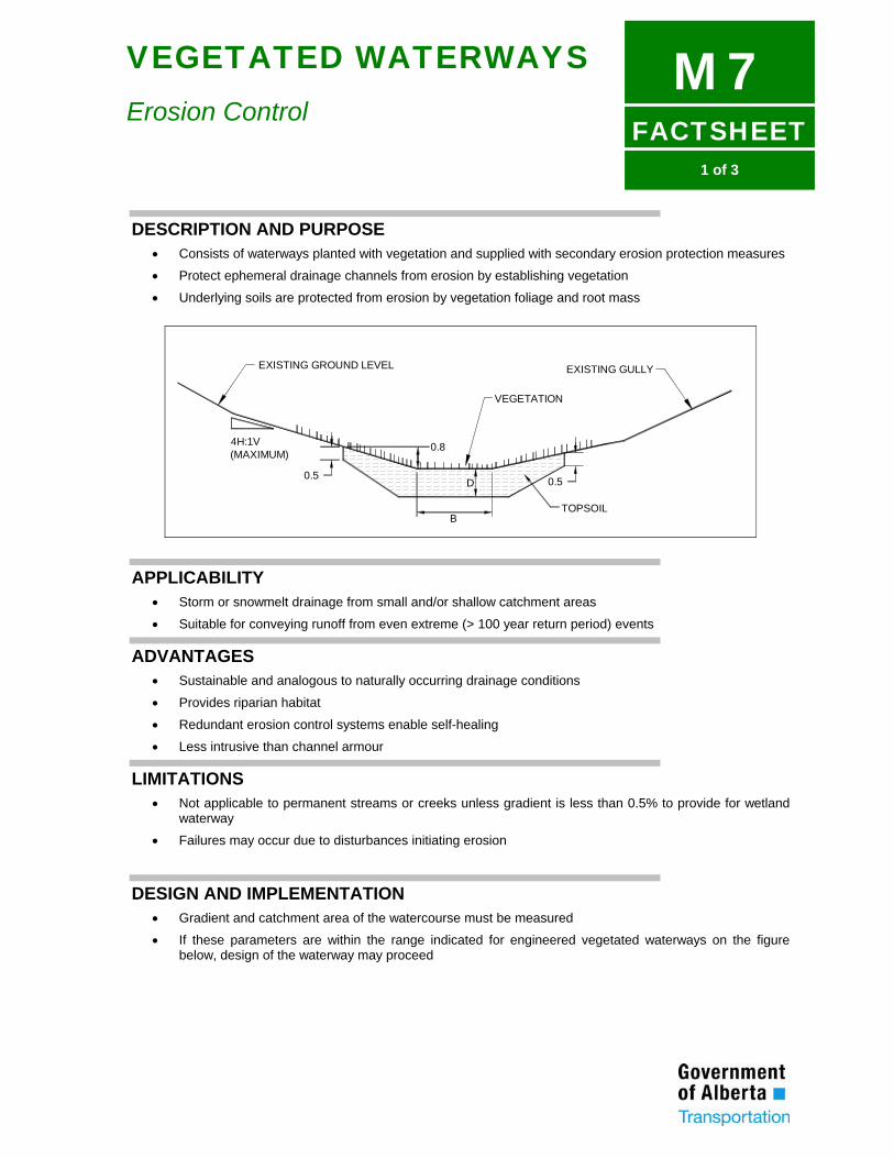
FACTSHEET
M71 of 3
VEGETATED WATERWAYS
Erosion Control
DESCRIPTION AND PURPOSE • Consists of waterways planted with vegetation and supplied with secondary erosion protection measures
• Protect ephemeral drainage channels from erosion by establishing vegetation
• Underlying soils are protected from erosion by vegetation foliage and root mass
EXISTING GROUND LEVEL EXISTING GULLY
VEGETATION
4H:1V(MAXIMUM)
0.5
0.8
0.5
TOPSOIL
D
B
APPLICABILITY • Storm or snowmelt drainage from small and/or shallow catchment areas
• Suitable for conveying runoff from even extreme (> 100 year return period) events
ADVANTAGES • Sustainable and analogous to naturally occurring drainage conditions
• Provides riparian habitat
• Redundant erosion control systems enable self-healing
• Less intrusive than channel armour
LIMITATIONS • Not applicable to permanent streams or creeks unless gradient is less than 0.5% to provide for wetland
waterway
• Failures may occur due to disturbances initiating erosion
DESIGN AND IMPLEMENTATION • Gradient and catchment area of the watercourse must be measured
• If these parameters are within the range indicated for engineered vegetated waterways on the figure below, design of the waterway may proceed
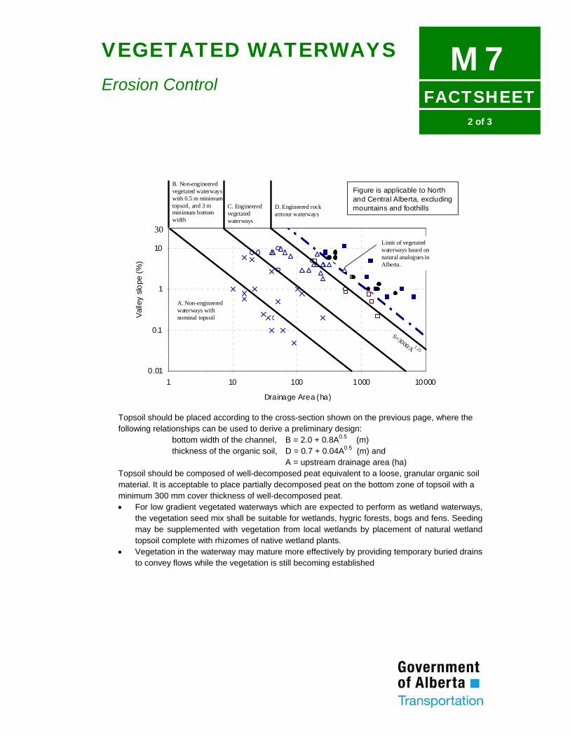
FACTSHEET
M72 of 3
VEGETATED WATERWAYS
Erosion Control
0.01
0.1
1
10
100
1 10 100 1000 10000
Drainage Area (ha)
Valle
y slo
pe (%
)
S=3000/A 1.25
Limit of vegetatedwaterways based onnatural analogues inAlberta.
B. Non-engineeredvegetated waterwayswith 0.5 m minimumtopsoil, and 3 mminimum bottomwidth
C. Engineeredvegetatedwaterways
D. Engineered rockarmour waterways
A. Non-engineeredwaterways withnominal topsoil
30
Figure is applicable to Northand Central Alberta, excludingmountains and foothills
Topsoil should be placed according to the cross-section shown on the previous page, where the following relationships can be used to derive a preliminary design: bottom width of the channel, B = 2.0 + 0.8A0.5 (m) thickness of the organic soil, D = 0.7 + 0.04A0.5 (m) and A = upstream drainage area (ha) Topsoil should be composed of well-decomposed peat equivalent to a loose, granular organic soil material. It is acceptable to place partially decomposed peat on the bottom zone of topsoil with a minimum 300 mm cover thickness of well-decomposed peat. For low gradient vegetated waterways which are expected to perform as wetland waterways,
the vegetation seed mix shall be suitable for wetlands, hygric forests, bogs and fens. Seeding may be supplemented with vegetation from local wetlands by placement of natural wetland topsoil complete with rhizomes of native wetland plants.
Vegetation in the waterway may mature more effectively by providing temporary buried drains to convey flows while the vegetation is still becoming established
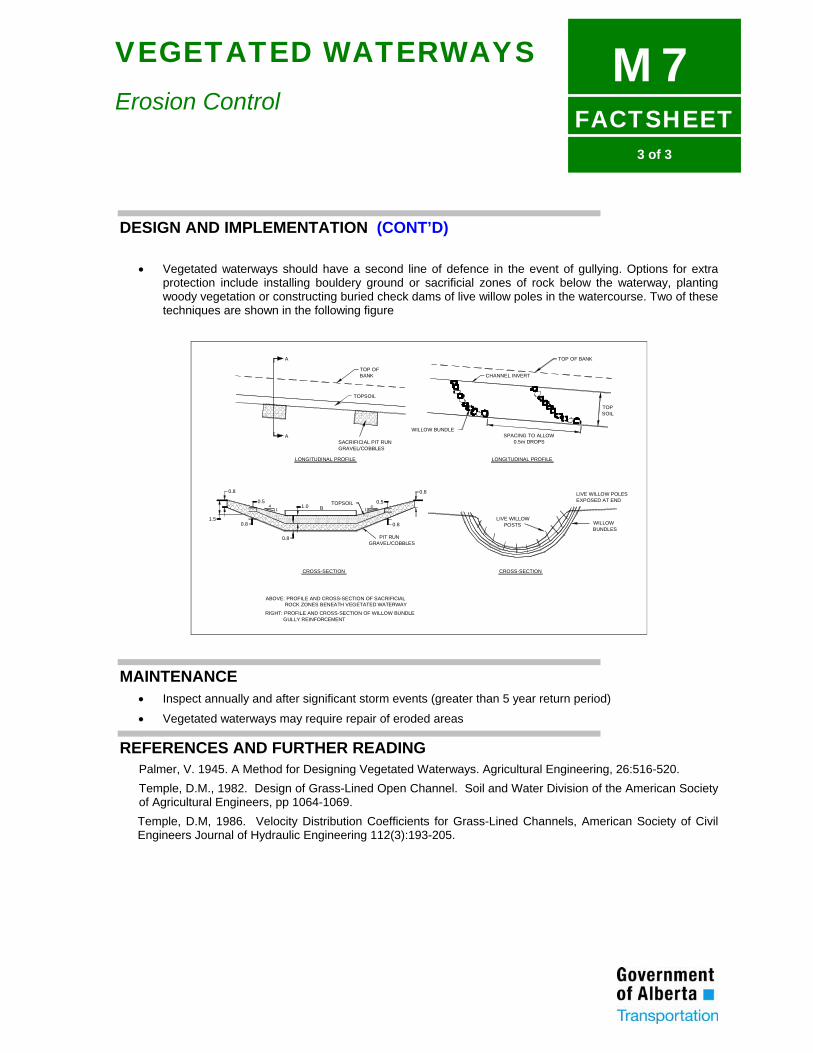
FACTSHEET
M73 of 3
VEGETATED WATERWAYS
Erosion Control
DESIGN AND IMPLEMENTATION (CONT’D)
• Vegetated waterways should have a second line of defence in the event of gullying. Options for extra protection include installing bouldery ground or sacrificial zones of rock below the waterway, planting woody vegetation or constructing buried check dams of live willow poles in the watercourse. Two of these techniques are shown in the following figure
TOP OF BANK
TOPSOIL
SACRIFICIAL PIT RUNGRAVEL/COBBLES
A
A
TOP OF BANK
CHANNEL INVERT
WILLOW BUNDLE
TOPSOIL
SPACING TO ALLOW0.5m DROPS
LONGITUDINAL PROFILE
PIT RUNGRAVEL/COBBLES
TOPSOILB
0.5
0.8
41
1.5
0.8
0.8
1.0
0.8
LIVE WILLOW POSTS WILLOW
BUNDLES
CROSS-SECTION
LIVE WILLOW POLESEXPOSED AT END
ABOVE: PROFILE AND CROSS-SECTION OF SACRIFICIAL ROCK ZONES BENEATH VEGETATED WATERWAY
RIGHT: PROFILE AND CROSS-SECTION OF WILLOW BUNDLE GULLY REINFORCEMENT
41
0.5
0.8
LONGITUDINAL PROFILE
CROSS-SECTION
MAINTENANCE • Inspect annually and after significant storm events (greater than 5 year return period)
• Vegetated waterways may require repair of eroded areas
REFERENCES AND FURTHER READING Palmer, V. 1945. A Method for Designing Vegetated Waterways. Agricultural Engineering, 26:516-520. Temple, D.M., 1982. Design of Grass-Lined Open Channel. Soil and Water Division of the American Society of Agricultural Engineers, pp 1064-1069. Temple, D.M, 1986. Velocity Distribution Coefficients for Grass-Lined Channels, American Society of Civil Engineers Journal of Hydraulic Engineering 112(3):193-205.
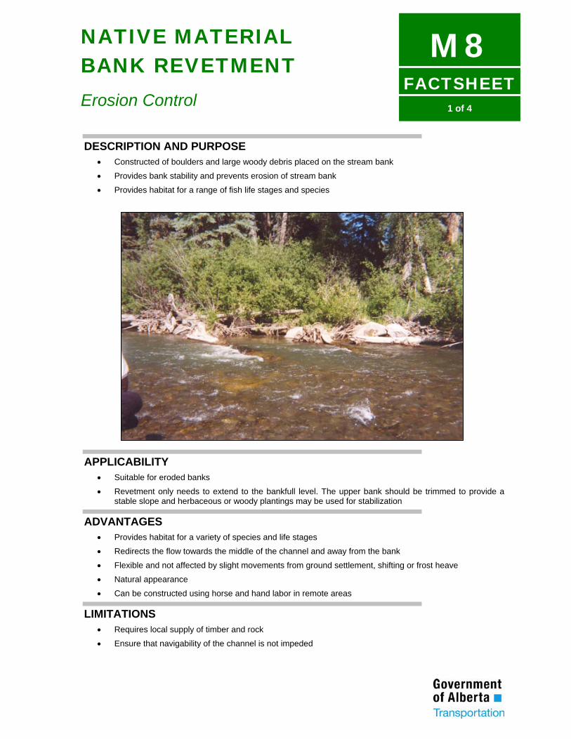
FACTSHEET
M81 of 4
NATIVE MATERIAL BANK REVETMENT
Erosion Control
DESCRIPTION AND PURPOSE • Constructed of boulders and large woody debris placed on the stream bank
• Provides bank stability and prevents erosion of stream bank
• Provides habitat for a range of fish life stages and species
APPLICABILITY • Suitable for eroded banks
• Revetment only needs to extend to the bankfull level. The upper bank should be trimmed to provide a stable slope and herbaceous or woody plantings may be used for stabilization
ADVANTAGES • Provides habitat for a variety of species and life stages
• Redirects the flow towards the middle of the channel and away from the bank
• Flexible and not affected by slight movements from ground settlement, shifting or frost heave
• Natural appearance
• Can be constructed using horse and hand labor in remote areas
LIMITATIONS • Requires local supply of timber and rock
• Ensure that navigability of the channel is not impeded
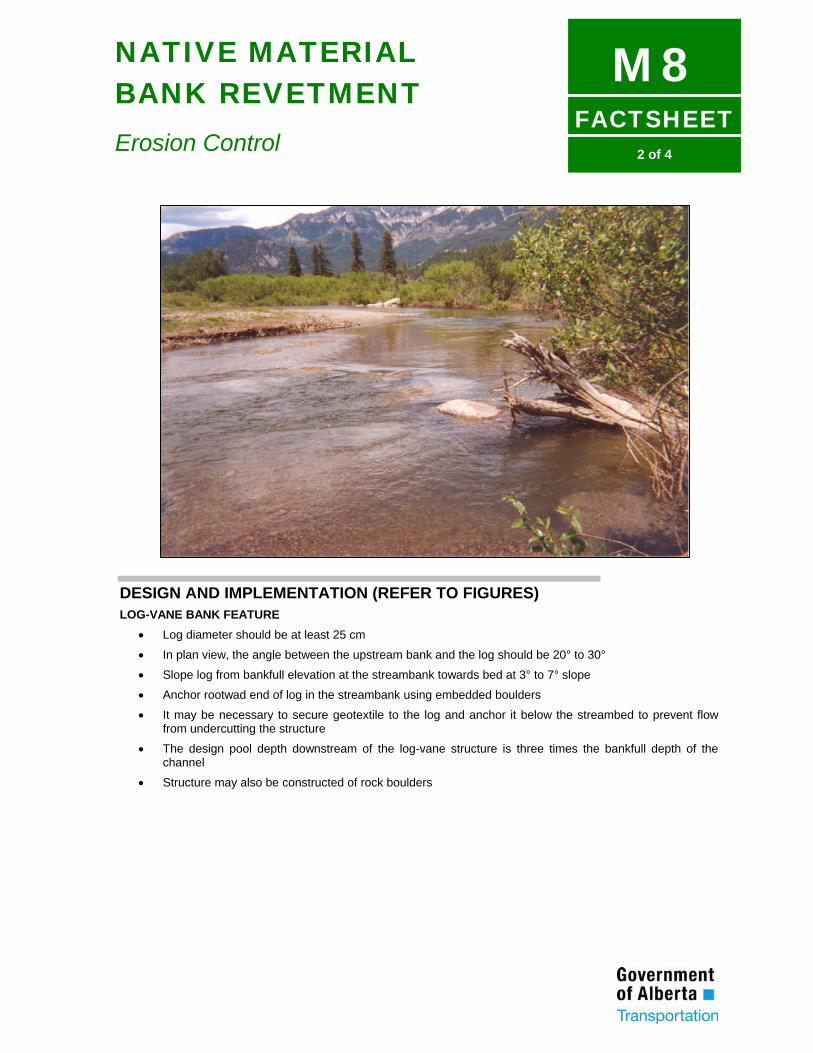
FACTSHEET
M82 of 4
NATIVE MATERIAL BANK REVETMENT
Erosion Control
DESIGN AND IMPLEMENTATION (REFER TO FIGURES) LOG-VANE BANK FEATURE
• Log diameter should be at least 25 cm
• In plan view, the angle between the upstream bank and the log should be 20° to 30°
• Slope log from bankfull elevation at the streambank towards bed at 3° to 7° slope
• Anchor rootwad end of log in the streambank using embedded boulders
• It may be necessary to secure geotextile to the log and anchor it below the streambed to prevent flow from undercutting the structure
• The design pool depth downstream of the log-vane structure is three times the bankfull depth of the channel
• Structure may also be constructed of rock boulders
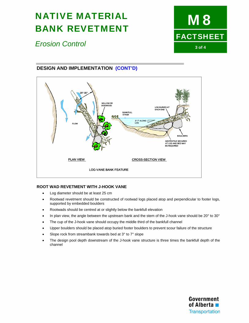
FACTSHEET
M83 of 4
NATIVE MATERIAL BANK REVETMENT
Erosion Control
DESIGN AND IMPLEMENTATION (CONT’D)
FLOW
20°-30°
3°-7° ALONGLOG
LOG BURIED ATEACH END
BANKFULLSTAGE
BOULDERS
GEOTEXTILE SECUREDAT LOG AND BED MAYBE REQUIRED
WILLOW ORDOGWOOD
PLAN VIEW CROSS-SECTION VIEW
LOG-VANE BANK FEATURE
FLOW
20°-30°
3°-7° ALONGLOG
LOG BURIED ATEACH END
BANKFULLSTAGE
BOULDERS
GEOTEXTILE SECUREDAT LOG AND BED MAYBE REQUIRED
WILLOW ORDOGWOOD
PLAN VIEW CROSS-SECTION VIEW
LOG-VANE BANK FEATURE
ROOT WAD REVETMENT WITH J-HOOK VANE
• Log diameter should be at least 25 cm
• Rootwad revetment should be constructed of rootwad logs placed atop and perpendicular to footer logs, supported by embedded boulders
• Rootwads should be centred at or slightly below the bankfull elevation
• In plan view, the angle between the upstream bank and the stem of the J-hook vane should be 20° to 30°
• The cup of the J-hook vane should occupy the middle third of the bankfull channel
• Upper boulders should be placed atop buried footer boulders to prevent scour failure of the structure
• Slope rock from streambank towards bed at 3° to 7° slope
• The design pool depth downstream of the J-hook vane structure is three times the bankfull depth of the channel
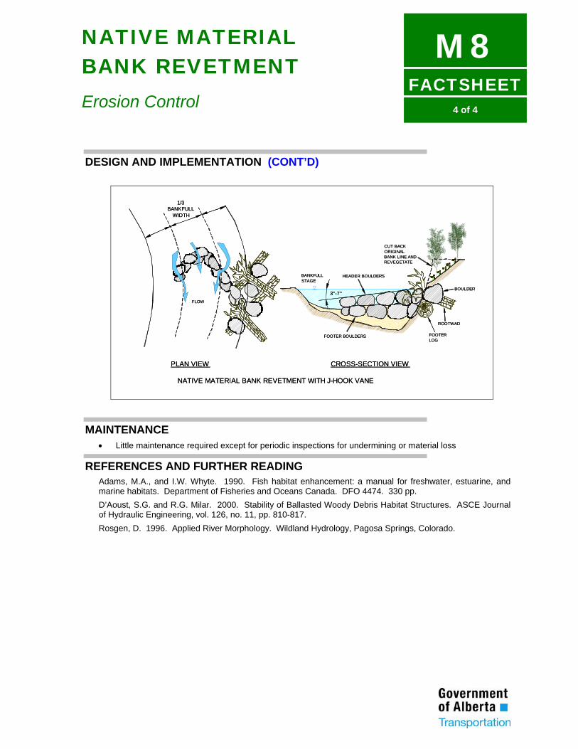
FACTSHEET
M84 of 4
NATIVE MATERIAL BANK REVETMENT
Erosion Control
DESIGN AND IMPLEMENTATION (CONT’D)
FLOW
BANKFULLWIDTH
1/3
PLAN VIEW
BANKFULLSTAGE
HEADER BOULDERS
FOOTER BOULDERS
BOULDER
ROOTWAD
FOOTERLOG
3°-7°
CUT BACKORIGINALBANK LINE ANDREVEGETATE
CROSS-SECTION VIEW
NATIVE MATERIAL BANK REVETMENT WITH J-HOOK VANE
FLOW
BANKFULLWIDTH
1/3
PLAN VIEW
BANKFULLSTAGE
HEADER BOULDERS
FOOTER BOULDERS
BOULDER
ROOTWAD
FOOTERLOG
CUT BACKORIGINALBANK LINE ANDREVEGETATE
CROSS-SECTION VIEW
NATIVE MATERIAL BANK REVETMENT WITH J-HOOK VANE
3°-7°
MAINTENANCE • Little maintenance required except for periodic inspections for undermining or material loss
REFERENCES AND FURTHER READING Adams, M.A., and I.W. Whyte. 1990. Fish habitat enhancement: a manual for freshwater, estuarine, and marine habitats. Department of Fisheries and Oceans Canada. DFO 4474. 330 pp. D’Aoust, S.G. and R.G. Milar. 2000. Stability of Ballasted Woody Debris Habitat Structures. ASCE Journal of Hydraulic Engineering, vol. 126, no. 11, pp. 810-817. Rosgen, D. 1996. Applied River Morphology. Wildland Hydrology, Pagosa Springs, Colorado.

APPENDIX II
FISH HABITAT COMPENSATION
TECHNIQUE FACTSHEETS

Page left blank intentionally
Appendix II-I
II. Fish Habitat Compensation Technique Factsheets
The following Factsheets provide representative examples of measures to compensate for impacts to fish habitat due to the construction of stream crossings, remaining after implementation of mitigation measures.
Each Factsheet provides a brief description of the measure, a review of conditions where it may be applicable, design provisions, implementation procedures and maintenance requirements. Drawings and figures are provided where applicable. The techniques presented in the Factsheets are standard compensation measures. A qualified professional should review their application to specific situations.
1) SUBSTRATE MODIFICATION
• C1: Log V-Weir
• C2: Log K-Dam
• C3: Opposing Wing Deflectors
• C4: Spawning Substrate Placement
• C5: Log Channel Constrictions
• C6: Log Sill
• C7: Walleye Spawning Riffle
2) COVER MODIFICATION
• C8: Woody Plantings
• C9: Herbaceous Plantings
• C10: Instream Boulder Placement
• C11: Deflector with Cover Log
• C12: Root Wads
3) HABITAT REPLACEMENT
• C13: Northern Pike Spawning Habitat
• C14: Gravel Side Channels
• C15: Shoreline Diversity

Appendix II-I
Page left blank intentionally
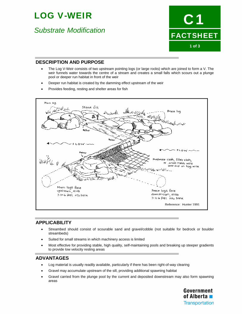
FACTSHEET
C11 of 3
LOG V-WEIR Substrate Modification
DESCRIPTION AND PURPOSE • The Log V-Weir consists of two upstream pointing logs (or large rocks) which are joined to form a V. The
weir funnels water towards the centre of a stream and creates a small falls which scours out a plunge pool or deeper run habitat in front of the weir
• Deeper run habitat is created by the damming effect upstream of the weir
• Provides feeding, resting and shelter areas for fish
APPLICABILITY • Streambed should consist of scourable sand and gravel/cobble (not suitable for bedrock or boulder
streambeds)
• Suited for small streams in which machinery access is limited
• Most effective for providing stable, high quality, self-maintaining pools and breaking up steeper gradients to provide low velocity resting areas
ADVANTAGES • Log material is usually readily available, particularly if there has been right-of-way clearing
• Gravel may accumulate upstream of the sill, providing additional spawning habitat
• Gravel carried from the plunge pool by the current and deposited downstream may also form spawning areas
Reference: Hunter 1991
FACTSHEET
C12 of 3
LOG V-WEIR Substrate Modification
LIMITATIONS • Best suited for small streams from 1-6 m wide
• May present an obstacle to navigability
• Suited for moderate to high gradient streams
• Best suited for streams with straight sections which are generally 10-15 cm deep during low flow periods
• Maintenance requirements can be high
• Not suitable for larger streams where flood depth submerges the logs and causes them to become buoyant
DESIGN AND IMPLEMENTATION (REFER TO FIGURE) • Straight, trimmed and de-barked conifer logs should be used to build the weir
• Main support logs should be set to slope down into the middle of the weir in order to confine the flow to middle of the stream. The bank tie-in location of the main logs should be 0.5 m above the apex
• For structural stability, the main logs should extend 2 m into each bank and be secured with rebar
• If the apex of the main logs is constructed above the level of the streambed, a damming effect will be created behind the weir. This intensifies the plunging action over the logs and causes more undercut erosion, requiring extra armouring along the underside of the weir
• If the apex of the main logs is constructed level to the streambed, there will be less of a damming effect behind the weir and no undercut erosion will result. In this case, armouring immediately under the weir will not be required
• For small streams (less than 3 m wide), the main log diameter should be 25-30 cm and for larger streams (3-6 m wide) the main log diameter should be 35-40 cm. If logs of sufficient diameter are not available, two smaller logs may be pinned together. Pinned logs are also easier to handle if heavy equipment is not available
• Heavy rebar pins (15 mm diameter) should be used to join the logs at the apex
• Two methods are available for stabilizing the entire structure:
• If log post pilings or a high-pressure water jet can be utilized, then four to six 10-15 cm diameter conifer posts should be driven deeply into the substrate immediately downstream of the weir. Two posts should be located near the apex, while two to four posts (depending on the stream width) should be evenly spaced along the weir crest. The posts should be pinned and wired to the main logs
FACTSHEET
C13 of 3
LOG V-WEIR Substrate Modification
DESIGN AND IMPLEMENTATION (CONT’D) • If post pilings are not feasible, then bracing logs should be attached perpendicular to the main logs using
rebar pins and buried 2 m into the bank. Rebar should then be used to secure the butt ends of the bracing logs into the bank
• Small wire mesh and geotextile should be attached to the upstream side of the main logs and extended 2 m upstream. This mesh will prevent the movement of cobbles and gravel underneath the structure. The retention of gravels and cobbles upstream of the structure may provide spawning habitat
• Boulders should be placed on the mesh, adjacent to the main logs, and cobbles should be placed over the boulders and the remaining mesh
• Boulders may be placed along the main logs near where they enter the banks to prevent bank erosion, enhance stability, and provide instream cover
• Large boulders may be added to the scour pool to increase the fish holding capacity. Other instream structures may be placed upstream and downstream of the log V-weir (refer to Factsheets C12, C13 and C14)
• The intended effect of the Log V-Notch Weir may also be achieved by a line of boulders partially buried into the streambed on the alignment of the main logs
• Designs and specifications for rock V weirs are given in Lowe (1996)
MAINTENANCE • The structure should be checked periodically to ensure it is functioning properly
• The structure should be examined after the first flood to ensure stability and to check for signs of bank erosion. Riprap may be placed if necessary
• The structure will eventually need replacement when the wood rots. Rock V weirs are more persistent.
REFERENCES AND FURTHER READING Frissel, C.A., and R.K. Nawa. 1992. Incidence and causes of physical failure of artificial habitat structures in streams of western Oregon and Washington. North American Journal of Fisheries Management 12:182-197. Hunt, R.L. 1993. Trout stream therapy. The University of Wisconsin Press. 74 pp. Hunter, C.J. 1991. Better trout habitat - A guide to stream restoration and management. Island Press, Washington, D.C. 320 pp. Lowe, S. 1996. Fish habitat enhancement structures - Typical designs. Alberta Environmental Protection, Water Resources Management Services. 44 pp.
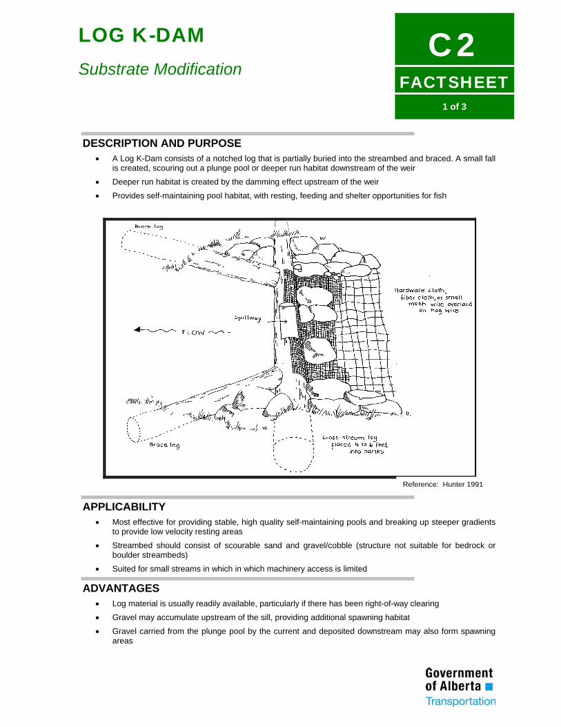
FACTSHEET
C21 of 3
LOG K-DAM
Substrate Modification
DESCRIPTION AND PURPOSE • A Log K-Dam consists of a notched log that is partially buried into the streambed and braced. A small fall
is created, scouring out a plunge pool or deeper run habitat downstream of the weir
• Deeper run habitat is created by the damming effect upstream of the weir
• Provides self-maintaining pool habitat, with resting, feeding and shelter opportunities for fish
APPLICABILITY • Most effective for providing stable, high quality self-maintaining pools and breaking up steeper gradients
to provide low velocity resting areas
• Streambed should consist of scourable sand and gravel/cobble (structure not suitable for bedrock or boulder streambeds)
• Suited for small streams in which in which machinery access is limited
ADVANTAGES • Log material is usually readily available, particularly if there has been right-of-way clearing
• Gravel may accumulate upstream of the sill, providing additional spawning habitat
• Gravel carried from the plunge pool by the current and deposited downstream may also form spawning areas
Reference: Hunter 1991
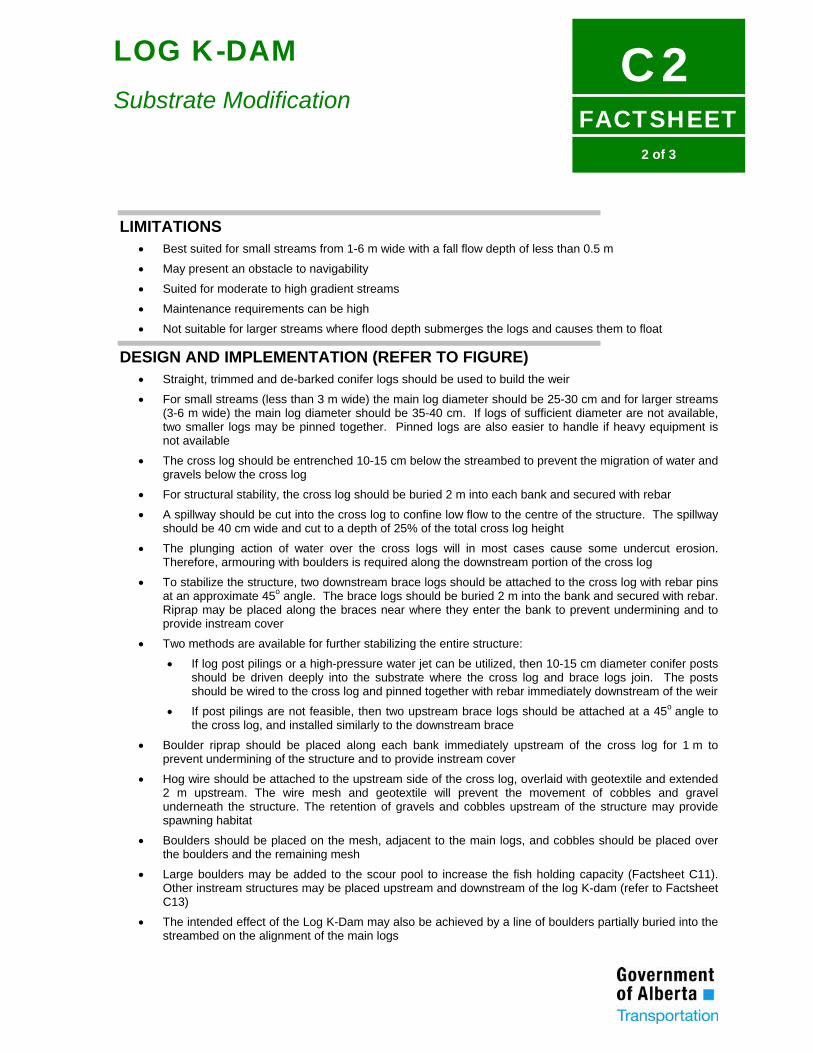
FACTSHEET
C22 of 3
LOG K-DAM
Substrate Modification
LIMITATIONS • Best suited for small streams from 1-6 m wide with a fall flow depth of less than 0.5 m
• May present an obstacle to navigability
• Suited for moderate to high gradient streams
• Maintenance requirements can be high
• Not suitable for larger streams where flood depth submerges the logs and causes them to float
DESIGN AND IMPLEMENTATION (REFER TO FIGURE) • Straight, trimmed and de-barked conifer logs should be used to build the weir
• For small streams (less than 3 m wide) the main log diameter should be 25-30 cm and for larger streams (3-6 m wide) the main log diameter should be 35-40 cm. If logs of sufficient diameter are not available, two smaller logs may be pinned together. Pinned logs are also easier to handle if heavy equipment is not available
• The cross log should be entrenched 10-15 cm below the streambed to prevent the migration of water and gravels below the cross log
• For structural stability, the cross log should be buried 2 m into each bank and secured with rebar
• A spillway should be cut into the cross log to confine low flow to the centre of the structure. The spillway should be 40 cm wide and cut to a depth of 25% of the total cross log height
• The plunging action of water over the cross logs will in most cases cause some undercut erosion. Therefore, armouring with boulders is required along the downstream portion of the cross log
• To stabilize the structure, two downstream brace logs should be attached to the cross log with rebar pins at an approximate 45o angle. The brace logs should be buried 2 m into the bank and secured with rebar. Riprap may be placed along the braces near where they enter the bank to prevent undermining and to provide instream cover
• Two methods are available for further stabilizing the entire structure:
• If log post pilings or a high-pressure water jet can be utilized, then 10-15 cm diameter conifer posts should be driven deeply into the substrate where the cross log and brace logs join. The posts should be wired to the cross log and pinned together with rebar immediately downstream of the weir
• If post pilings are not feasible, then two upstream brace logs should be attached at a 45o angle to the cross log, and installed similarly to the downstream brace
• Boulder riprap should be placed along each bank immediately upstream of the cross log for 1 m to prevent undermining of the structure and to provide instream cover
• Hog wire should be attached to the upstream side of the cross log, overlaid with geotextile and extended 2 m upstream. The wire mesh and geotextile will prevent the movement of cobbles and gravel underneath the structure. The retention of gravels and cobbles upstream of the structure may provide spawning habitat
• Boulders should be placed on the mesh, adjacent to the main logs, and cobbles should be placed over the boulders and the remaining mesh
• Large boulders may be added to the scour pool to increase the fish holding capacity (Factsheet C11). Other instream structures may be placed upstream and downstream of the log K-dam (refer to Factsheet C13)
• The intended effect of the Log K-Dam may also be achieved by a line of boulders partially buried into the streambed on the alignment of the main logs
FACTSHEET
C23 of 3
LOG K-DAM
Substrate Modification
MAINTENANCE • The structure should be checked periodically to ensure it is functioning properly
• The structure should be examined after the first flood to ensure stability and to check for signs of bank erosion. Riprap may be placed if necessary
• The structure will eventually need replacement when the wood rots
REFERENCES AND FURTHER READING Frissel, C.A., and R.K. Nawa. 1992. Incidence and causes of physical failure of artificial habitat structures in streams of western Oregon and Washington. North American Journal of Fisheries Management 12:182-197. Hunt, R.L. 1993. Trout stream therapy. The University of Wisconsin Press. 74 pp. Hunter, C.J. 1991. Better trout habitat - A guide to stream restoration and management. Island Press, Washington, D.C. 320 pp. Lowe, S. 1996. Fish habitat enhancement structures - Typical designs. Alberta Environmental Protection, Water Resources Management Services. 44 pp.
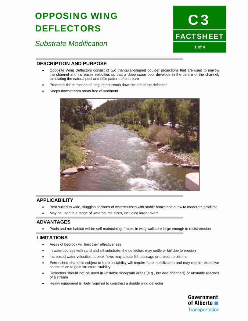
FACTSHEET
C31 of 4
OPPOSING WING DEFLECTORS
Substrate Modification
DESCRIPTION AND PURPOSE • Opposite Wing Deflectors consist of two triangular-shaped boulder projections that are used to narrow
the channel and increases velocities so that a deep scour pool develops in the centre of the channel, simulating the natural pool and riffle pattern of a stream
• Promotes the formation of long, deep trench downstream of the deflector
• Keeps downstream areas free of sediment
APPLICABILITY • Best suited to wide, sluggish sections of watercourses with stable banks and a low to moderate gradient
• May be used in a range of watercourse sizes, including larger rivers
ADVANTAGES • Pools and run habitat will be self-maintaining if rocks in wing walls are large enough to resist erosion
LIMITATIONS • Areas of bedrock will limit their effectiveness
• In watercourses with sand and silt substrate, the deflectors may settle or fail due to erosion
• Increased water velocities at peak flows may create fish passage or erosion problems
• Entrenched channels subject to bank instability will require bank stabilization and may require extensive construction to gain structural stability
• Deflectors should not be used in unstable floodplain areas (e.g., braided channels) or unstable reaches of a stream
• Heavy equipment is likely required to construct a double wing deflector
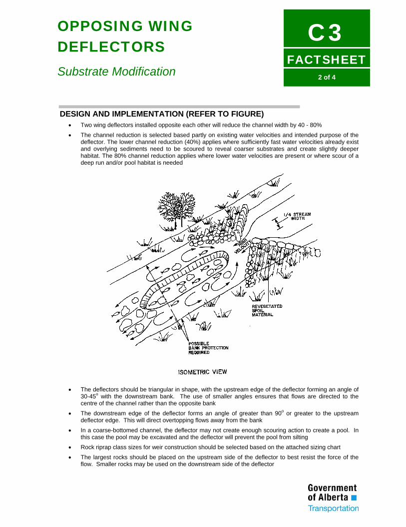
FACTSHEET
C32 of 4
OPPOSING WING DEFLECTORS
Substrate Modification
DESIGN AND IMPLEMENTATION (REFER TO FIGURE) • Two wing deflectors installed opposite each other will reduce the channel width by 40 - 80%
• The channel reduction is selected based partly on existing water velocities and intended purpose of the deflector. The lower channel reduction (40%) applies where sufficiently fast water velocities already exist and overlying sediments need to be scoured to reveal coarser substrates and create slightly deeper habitat. The 80% channel reduction applies where lower water velocities are present or where scour of a deep run and/or pool habitat is needed
• The deflectors should be triangular in shape, with the upstream edge of the deflector forming an angle of
30-45o with the downstream bank. The use of smaller angles ensures that flows are directed to the centre of the channel rather than the opposite bank
• The downstream edge of the deflector forms an angle of greater than 90o or greater to the upstream deflector edge. This will direct overtopping flows away from the bank
• In a coarse-bottomed channel, the deflector may not create enough scouring action to create a pool. In this case the pool may be excavated and the deflector will prevent the pool from silting
• Rock riprap class sizes for weir construction should be selected based on the attached sizing chart
• The largest rocks should be placed on the upstream side of the deflector to best resist the force of the flow. Smaller rocks may be used on the downstream side of the deflector
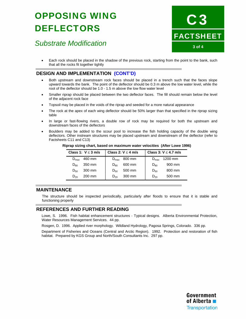
FACTSHEET
C33 of 4
OPPOSING WING DEFLECTORS
Substrate Modification
• Each rock should be placed in the shadow of the previous rock, starting from the point to the bank, such that all the rocks fit together tightly
DESIGN AND IMPLEMENTATION (CONT’D) • Both upstream and downstream rock faces should be placed in a trench such that the faces slope
upward towards the bank. The point of the deflector should be 0.3 m above the low water level, while the root of the deflector should be 1.0 - 1.5 m above the low flow water level
• Smaller riprap should be placed between the two deflector faces. The fill should remain below the level of the adjacent rock face
• Topsoil may be placed in the voids of the riprap and seeded for a more natural appearance
• The rock at the apex of each wing deflector should be 50% larger than that specified in the riprap sizing table
• In large or fast-flowing rivers, a double row of rock may be required for both the upstream and downstream faces of the deflectors
• Boulders may be added to the scour pool to increase the fish holding capacity of the double wing deflectors. Other instream structures may be placed upstream and downstream of the deflector (refer to Factsheets C11 and C13)
Riprap sizing chart, based on maximum water velocities (After Lowe 1996)
Class 1: V ≤ 3 m/s Class 2: V ≤ 4 m/s Class 3: V ≤ 4.7 m/s
Dmax 460 mm Dmax 800 mm Dmax 1200 mm D80 350 mm D80 600 mm D80 900 mm D50 300 mm D50 500 mm D50 800 mm D20 200 mm D20 300 mm D20 500 mm
MAINTENANCE The structure should be inspected periodically, particularly after floods to ensure that it is stable and functioning properly
REFERENCES AND FURTHER READING Lowe, S. 1996. Fish habitat enhancement structures - Typical designs. Alberta Environmental Protection, Water Resources Management Services. 44 pp. Rosgen, D. 1996. Applied river morphology. Wildland Hydrology, Pagosa Springs, Colorado. 336 pp. Department of Fisheries and Oceans (Central and Arctic Region). 1992. Protection and restoration of fish habitat. Prepared by KGS Group and North/South Consultants Inc. 297 pp.
FACTSHEET
C41 of 2
SPAWNING SUBSTRATE PLACEMENT
Substrate Modification
DESCRIPTION AND PURPOSE • Spawning substrate placement is a technique where appropriate-sized gravel and cobble is secured into
the stream substrate to provide for salmonid spawning
• Increases the amount of spawning substrate where this component is lacking
• Increases the natural recruitment of fry
APPLICABILITY • Suited to streams where substrate quality and/or quantity limit natural recruitment to the population (e.g.,
streams located below lakes or those which are groundwater fed)
ADVANTAGES • Inexpensive material cost
• Substrate placement has a natural appearance
• Increased substrate diversity leads to increased invertebrate production
LIMITATIONS • Best suited to small to moderate-sized watercourses where the critical shear velocity for the placed
gravel is not exceeded during flood stages
• Most appropriate in streams with stable bottoms which are not subject to severe flooding or ice scour
• Not suited to streams with predominantly sand or silt/clay substrate, as the spawning bed area may fill in with finer bedload transported material
DESIGN AND IMPLEMENTATION • The critical shear stress required to mobilize various gravel sizes under different flow regimes should be
calculated in order to determine the appropriate gravel size
• Construction should be carried out during summer low flows
• An area not currently used as a spawning area must be selected for substrate placement
• A site with a water velocity of 0.35 to 0.70 m/s and a water depth from 0.2 to 0.4 m should be selected. The selection of appropriate velocity areas is important as lower velocity areas will accumulate excessive amounts of fines, reducing the effectiveness of the gravel placement
• Stream widenings are ideal locations as excessive stream energy is dissipated here and the effects of scouring are lessened
• Transitional areas between riffle and pool area are also suitable for gravel placement
• Only rounded, washed gravels should be used. Recommended substrate sizes vary with watershed, species and fish size at maturity, and the design must recognize local requirements
• The proposed spawning bed should be staked approximately 3 to 4 m long and 1 to 2 m wide. A long and narrow design configuration decreases the scouring effects of ice and high water
• All rocks and boulders should be removed from the staked area. The existing substrate should be excavated to a depth of 0.2 to 0.3 m
• To stabilize the placed gravels, several large boulders should be installed at the downstream base of the bed. These should be extended no more than 5 to 10 cm above the natural stream bed
FACTSHEET
C42 of 2
SPAWNING SUBSTRATE PLACEMENT
Substrate Modification
DESIGN AND IMPLEMENTATION (CONT’D) • Boulders should not be placed at the upstream end of the spawning area, as this may promote scouring
• The excavated area should be filled with the washed gravel to the level of the natural stream bed
• To enhance the spawning area, instream cover may be placed nearby to provide shelter for adult and fry fish (refer to Factsheet C11)
MAINTENANCE • Periodic inspections are required to ensure gravel stability
• Gravels which show signs of movement can be stabilized by installing a catchment structure (refer to Factsheet C6)
REFERENCES AND FURTHER READING Adams, M.A., and I.W. Whyte. 1990. Fish habitat enhancement: a manual for freshwater, estuarine, and marine habitats. Department of Fisheries and Oceans Canada. DFO 4474. 330 pp. Kondolf, G.M., J.C. Vick, and T.M. Ramirez. 1996. Salmon spawning habitat rehabilitation on the Merced River, California: An evaluation of project planning and performance. Transactions of the American Fisheries Society 125: 899-912. Ontario Ministry of Natural Resources. 1984. Community fisheries involvement program - Field manual - Part 1: Trout stream rehabilitation. Queen’s Printer for Ontario. 273 pp. Rosgen, D. 1996. Applied river morphology. Wildland Hydrology, Pagosa Springs, Colorado. 336 pp.
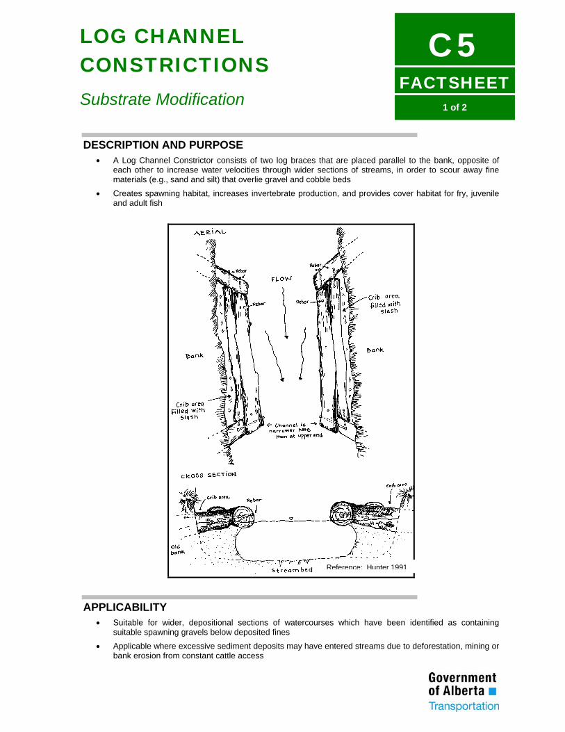
FACTSHEET
C51 of 2
LOG CHANNEL CONSTRICTIONS
Substrate Modification
DESCRIPTION AND PURPOSE • A Log Channel Constrictor consists of two log braces that are placed parallel to the bank, opposite of
each other to increase water velocities through wider sections of streams, in order to scour away fine materials (e.g., sand and silt) that overlie gravel and cobble beds
• Creates spawning habitat, increases invertebrate production, and provides cover habitat for fry, juvenile and adult fish
APPLICABILITY • Suitable for wider, depositional sections of watercourses which have been identified as containing
suitable spawning gravels below deposited fines
• Applicable where excessive sediment deposits may have entered streams due to deforestation, mining or bank erosion from constant cattle access
Reference: Hunter 1991
FACTSHEET
C52 of 2
LOG CHANNEL CONSTRICTIONS
Substrate Modification
ADVANTAGES • Suitable for low to high gradient streams
• Has a natural appearance
LIMITATIONS • Unsuitable for watercourses with a bedrock substrate
• May impede fish passage due to increased velocities during peak flows
• Unstable banks downstream of the constrictor may need to be stabilized with boulder riprap
• Limited to smaller streams with an average width of less than 12 m
• Heavy equipment may be required for construction
DESIGN AND IMPLEMENTATION (REFER TO FIGURE) • An appropriate section of stream with heavy silt deposits overlying a gravel substrate should be identified
• Most guidelines call for a reduction of 40 to 80% of the stream width
• An 80% stream width reduction will create a deep scour pool below the structure. However, to scour silt deposits a 50% reduction in stream width should suffice
• A channel constrictor consists of a main channel log with two brace logs pinned to it at approximately 45o
angles along each bank
• The main log should be 3 to 9 m long, 35 to 50 cm in diameter, and slightly crooked to provide better cover and promote self-cleaning
• The main log may be notched out along the underside to increase cover for adult fish
• The main log should be dug into a trench parallel to the bank so that 15 to 30 cm is exposed during the low flow period
• The constrictor should be 15 to 30 cm narrower at the downstream end than the upstream end to maintain the water velocity throughout the constrictor length and prevent silting of the structure
• 15 mm steel rebar should be used to pin the main logs to the brace logs and anchor into the substrate
• Brace logs should be keyed into the bank 1.5 to 2.0 m, using rebar to secure them
• To provide for undercutting, two logs should be pinned to each of the brace logs, perpendicular to the main log. The excavated area should be filled with smaller boulders, and covered with topsoil to promote the growth of vegetation
MAINTENANCE • Periodic inspections are required to ensure that logs remain keyed into the bank and that bank erosion
has not been initiated
REFERENCES AND FURTHER READING Hunter, C.J. 1991. Better trout habitat - A guide to stream restoration and management. Island Press, Washington, D.C. 320 pp. Orth, D.J., and R.J. White. 1993. Stream habitat management. Pages 205-230 in C.C. Kohler and W.A. Hubert, editors. Inland fisheries management in North America. American Fisheries Society, Bethesda, Maryland. 594 pp. Rosgen, D. 1996. Applied river morphology. Wildland Hydrology, Pagosa Springs, Colorado. 336 pp.
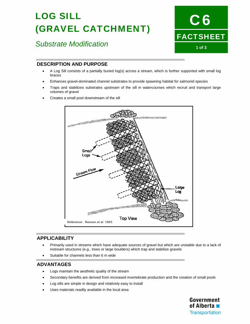
FACTSHEET
C61 of 3
LOG SILL (GRAVEL CATCHMENT) Substrate Modification
DESCRIPTION AND PURPOSE • A Log Sill consists of a partially buried log(s) across a stream, which is further supported with small log
braces
• Enhances gravel-dominated channel substrates to provide spawning habitat for salmonid species
• Traps and stabilizes substrates upstream of the sill in watercourses which recruit and transport large volumes of gravel
• Creates a small pool downstream of the sill
APPLICABILITY • Primarily used in streams which have adequate sources of gravel but which are unstable due to a lack of
instream structures (e.g., trees or large boulders) which trap and stabilize gravels
• Suitable for channels less than 6 m wide
ADVANTAGES • Logs maintain the aesthetic quality of the stream
• Secondary benefits are derived from increased invertebrate production and the creation of small pools
• Log sills are simple in design and relatively easy to install
• Uses materials readily available in the local area
Reference: Reeves et al. 1993
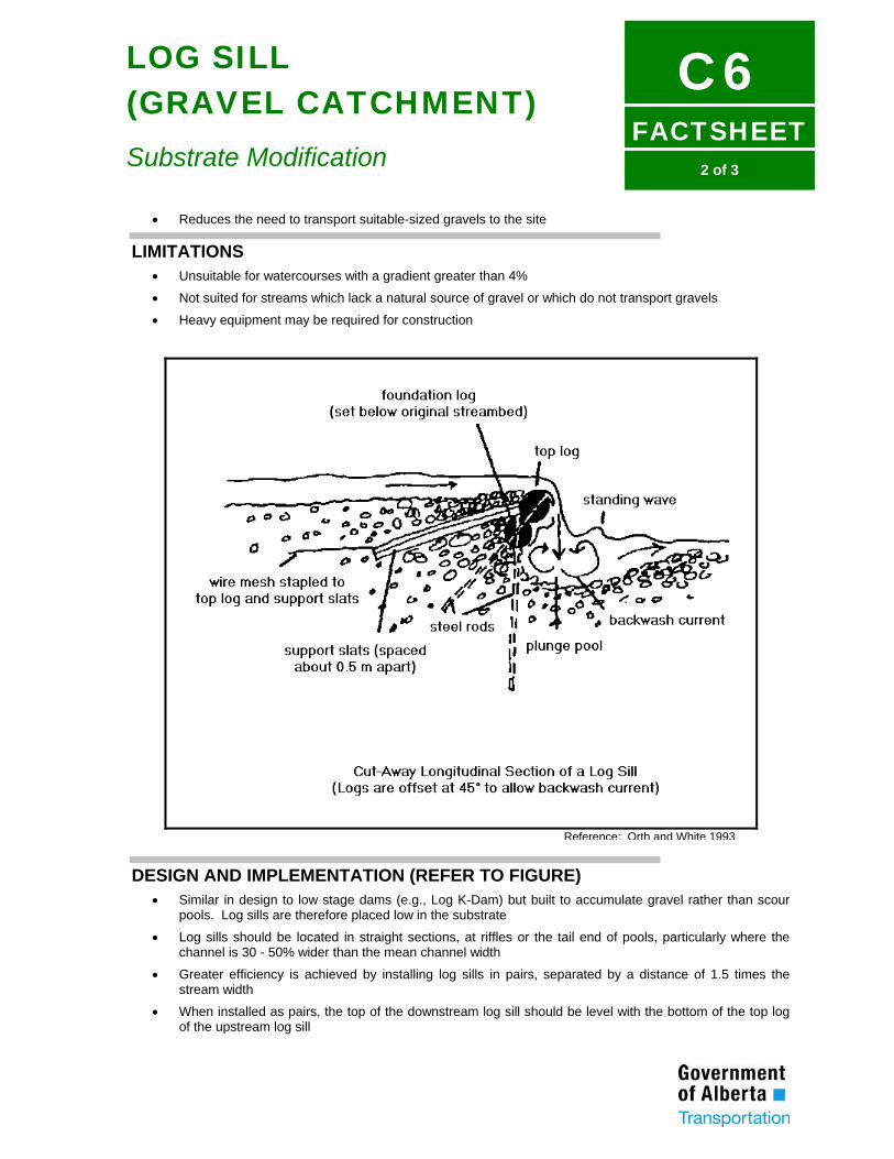
FACTSHEET
C62 of 3
LOG SILL (GRAVEL CATCHMENT) Substrate Modification
• Reduces the need to transport suitable-sized gravels to the site
LIMITATIONS • Unsuitable for watercourses with a gradient greater than 4%
• Not suited for streams which lack a natural source of gravel or which do not transport gravels
• Heavy equipment may be required for construction
DESIGN AND IMPLEMENTATION (REFER TO FIGURE) • Similar in design to low stage dams (e.g., Log K-Dam) but built to accumulate gravel rather than scour
pools. Log sills are therefore placed low in the substrate
• Log sills should be located in straight sections, at riffles or the tail end of pools, particularly where the channel is 30 - 50% wider than the mean channel width
• Greater efficiency is achieved by installing log sills in pairs, separated by a distance of 1.5 times the stream width
• When installed as pairs, the top of the downstream log sill should be level with the bottom of the top log of the upstream log sill
Reference: Orth and White 1993
FACTSHEET
C63 of 3
LOG SILL (GRAVEL CATCHMENT) Substrate Modification
DESIGN AND IMPLEMENTATION (CONT’D) • Log sills should be built using an offset double-log design whereby the upper log overhangs the
downstream side of the bottom log. This allows water to plunge from the top log and backwash beneath the structure. The small plunge pool and overhanging sill will provide cover for fish
• Two 25 - 30 cm diameter conifer logs should be used. The bottom log should be buried in a trench so that the top of the log is even with the substrate. Both logs should extend 2 m into each bank
• The bottom log should be secured by driving 1.5 m lengths of 15 mm rebar through the log and into the streambed
• The top log should be secured to the bottom log by drilling holes through the two logs at 45o and driving 1.5 m lengths of 15 mm rebar through both logs and into streambed
• Backfill and boulder riprap should be used to armour and secure the logs where they abut the bank
• 4.5 x 9.0 cm conifer slats or similar-sized logs should be nailed across the top of the log sill and extended into the streambed on 0.5 m spacing. Gravel should be placed behind the log sill and sloped to the top log
• Fencing material should be nailed to the top of the sill and onto the slats
MAINTENANCE • The sill should be monitored to ensure it is functioning as designed
• Gravel may be placed upstream of log sills which are stable but not trapping gravel
• Abutments should be checked for signs of erosion and stabilized as required
• Replacement may be required when logs rot
REFERENCES AND FURTHER READING Adams, M.A., and I.W. Whyte. 1990. Fish habitat enhancement: a manual for freshwater, estuarine, and marine habitats. Department of Fisheries and Oceans Canada. DFO 4474. 330 pp. House, R.A., and P.L. Boehne. 1985. Evaluation of instream structures for salmonid spawning and rearing in a coastal Oregon stream. North American Journal of Fisheries Management 5: 283-295. Hunter, C.J. 1991. Better trout habitat - A guide to stream restoration and management. Island Press, Washington, D.C. 320 pp. Orth, D.J., and R.J. White. 1993. Stream habitat management. Pages 205-230 in C.C. Kohler and W.A. Hubert, editors. Inland fisheries management in North America. American Fisheries Society, Bethesda, Maryland. 594 pp. Reeves, G.H., J.D. Hall, T.D. Roelofs, T.L. Hickman, and C.O. Baker. 1991. Rehabilitating and modifying stream habitats. Pages 519-557 in W.R. Meehan, editor. Influences of forest and rangeland management on salmonid fishes and their habitats. American Fisheries Society Special Publication 19. 751 pp. Rosgen, D. 1996. Applied river morphology. Wildland Hydrology, Pagosa Springs, Colorado. 336 pp.
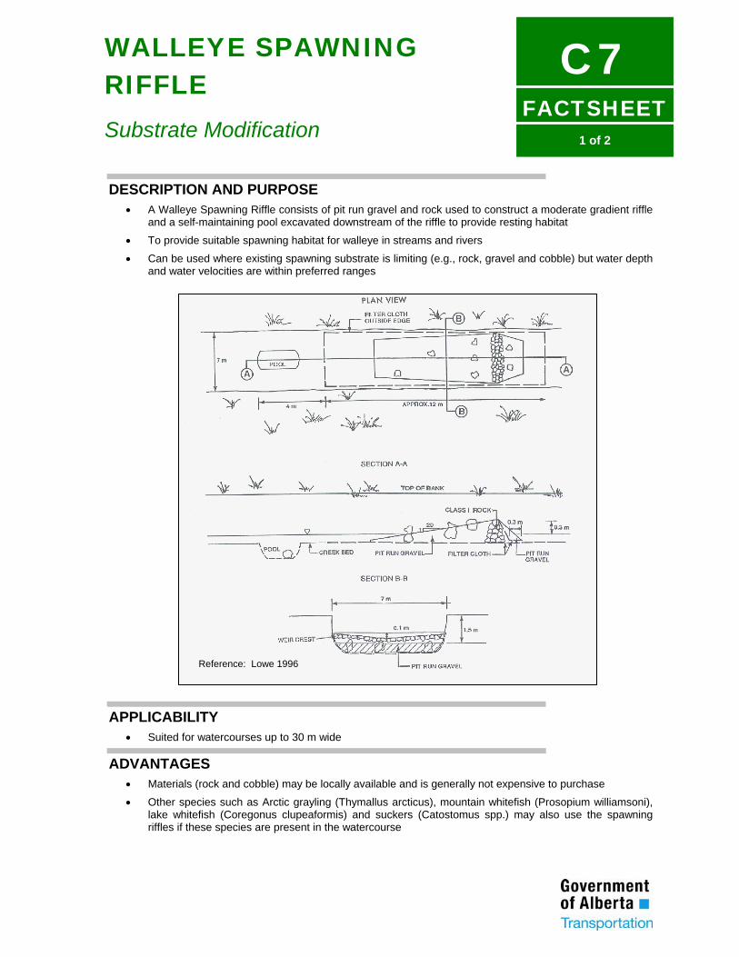
FACTSHEET
C71 of 2
WALLEYE SPAWNING RIFFLE
Substrate Modification
DESCRIPTION AND PURPOSE • A Walleye Spawning Riffle consists of pit run gravel and rock used to construct a moderate gradient riffle
and a self-maintaining pool excavated downstream of the riffle to provide resting habitat
• To provide suitable spawning habitat for walleye in streams and rivers
• Can be used where existing spawning substrate is limiting (e.g., rock, gravel and cobble) but water depth and water velocities are within preferred ranges
APPLICABILITY • Suited for watercourses up to 30 m wide
ADVANTAGES • Materials (rock and cobble) may be locally available and is generally not expensive to purchase
• Other species such as Arctic grayling (Thymallus arcticus), mountain whitefish (Prosopium williamsoni), lake whitefish (Coregonus clupeaformis) and suckers (Catostomus spp.) may also use the spawning riffles if these species are present in the watercourse
Reference: Lowe 1996
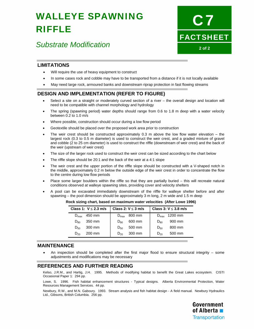
FACTSHEET
C72 of 2
WALLEYE SPAWNING RIFFLE
Substrate Modification
LIMITATIONS • Will require the use of heavy equipment to construct
• In some cases rock and cobble may have to be transported from a distance if it is not locally available
• May need large rock, armoured banks and downstream riprap protection in fast flowing streams
DESIGN AND IMPLEMENTATION (REFER TO FIGURE) • Select a site on a straight or moderately curved section of a river – the overall design and location will
need to be compatible with channel morphology and hydrology
• The spring (spawning period) water depths should range from 0.6 to 1.8 m deep with a water velocity between 0.2 to 1.0 m/s
• Where possible, construction should occur during a low flow period
• Geotextile should be placed over the proposed work area prior to construction
• The weir crest should be constructed approximately 0.3 m above the low flow water elevation – the largest rock (0.3 to 0.5 m diameter) is used to construct the weir crest, and a graded mixture of gravel and cobble (2 to 25 cm diameter) is used to construct the riffle (downstream of weir crest) and the back of the weir (upstream of weir crest)
• The size of the larger rock used to construct the weir crest can be sized according to the chart below
• The riffle slope should be 20:1 and the back of the weir at a 4:1 slope
• The weir crest and the upper portion of the riffle slope should be constructed with a V-shaped notch in the middle, approximately 0.2 m below the outside edge of the weir crest in order to concentrate the flow to the centre during low flow periods
• Place some larger boulders within the riffle so that they are partially buried – this will recreate natural conditions observed at walleye spawning sites, providing cover and velocity shelters
• A pool can be excavated immediately downstream of the riffle for walleye shelter before and after spawning – the pool dimension should be approximately 3 m long, 2 m wide and 1.5 m deep
Rock sizing chart, based on maximum water velocities (After Lowe 1996)
Class 1: V ≤ 2.3 m/s Class 2: V ≤ 3 m/s Class 3: V ≤ 3.8 m/s
Dmax 450 mm Dmax 800 mm Dmax 1200 mm D80 350 mm D80 600 mm D80 900 mm D50 300 mm D50 500 mm D50 800 mm D20 200 mm D20 300 mm D20 500 mm
MAINTENANCE • An inspection should be completed after the first major flood to ensure structural integrity – some
adjustments and modifications may be necessary
REFERENCES AND FURTHER READING Kelso, J.R.M., and Hartig, J.H. 1995. Methods of modifying habitat to benefit the Great Lakes ecosystem. CISTI Occasional Paper 1: 294 pp. Lowe, S. 1996. Fish habitat enhancement structures - Typical designs. Alberta Environmental Protection, Water Resources Management Services. 44 pp. Newbury, R.W., and M.N. Gaboury. 1993. Stream analysis and fish habitat design - A field manual. Newbury Hydraulics Ltd., Gibsons, British Columbia. 256 pp.
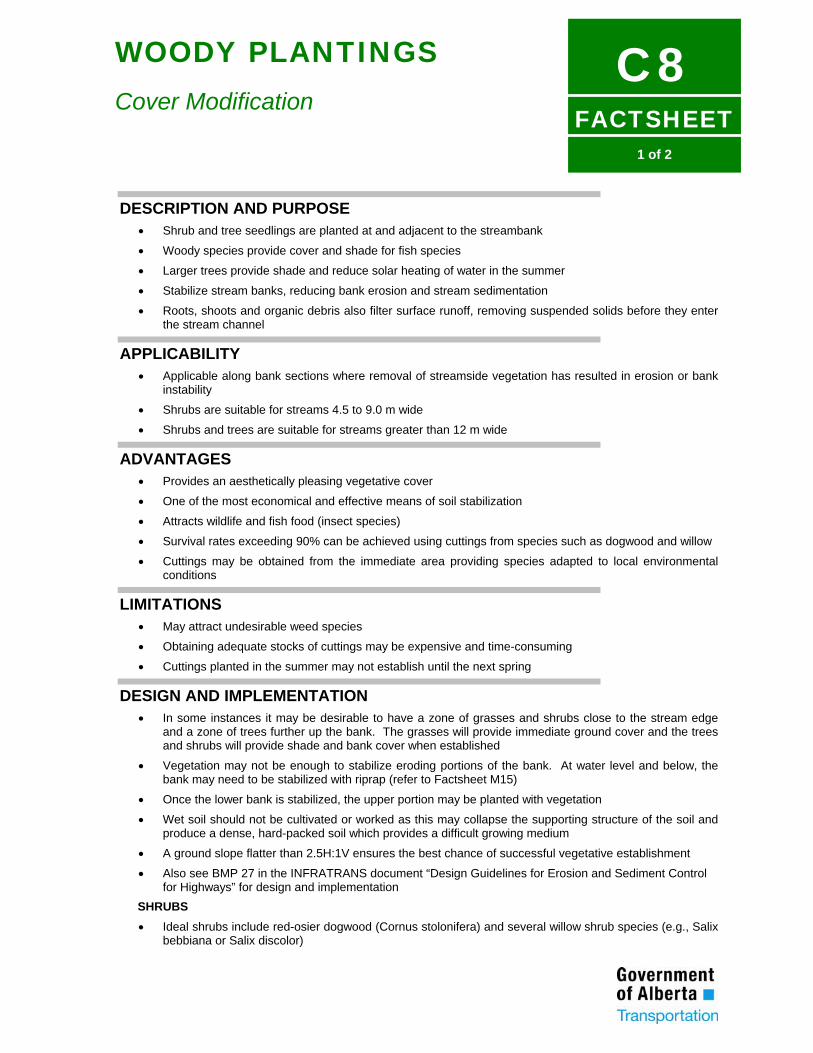
FACTSHEET
C81 of 2
WOODY PLANTINGS
Cover Modification
DESCRIPTION AND PURPOSE • Shrub and tree seedlings are planted at and adjacent to the streambank
• Woody species provide cover and shade for fish species
• Larger trees provide shade and reduce solar heating of water in the summer
• Stabilize stream banks, reducing bank erosion and stream sedimentation
• Roots, shoots and organic debris also filter surface runoff, removing suspended solids before they enter the stream channel
APPLICABILITY • Applicable along bank sections where removal of streamside vegetation has resulted in erosion or bank
instability
• Shrubs are suitable for streams 4.5 to 9.0 m wide
• Shrubs and trees are suitable for streams greater than 12 m wide
ADVANTAGES • Provides an aesthetically pleasing vegetative cover
• One of the most economical and effective means of soil stabilization
• Attracts wildlife and fish food (insect species)
• Survival rates exceeding 90% can be achieved using cuttings from species such as dogwood and willow
• Cuttings may be obtained from the immediate area providing species adapted to local environmental conditions
LIMITATIONS • May attract undesirable weed species
• Obtaining adequate stocks of cuttings may be expensive and time-consuming
• Cuttings planted in the summer may not establish until the next spring
DESIGN AND IMPLEMENTATION • In some instances it may be desirable to have a zone of grasses and shrubs close to the stream edge
and a zone of trees further up the bank. The grasses will provide immediate ground cover and the trees and shrubs will provide shade and bank cover when established
• Vegetation may not be enough to stabilize eroding portions of the bank. At water level and below, the bank may need to be stabilized with riprap (refer to Factsheet M15)
• Once the lower bank is stabilized, the upper portion may be planted with vegetation
• Wet soil should not be cultivated or worked as this may collapse the supporting structure of the soil and produce a dense, hard-packed soil which provides a difficult growing medium
• A ground slope flatter than 2.5H:1V ensures the best chance of successful vegetative establishment
• Also see BMP 27 in the INFRATRANS document “Design Guidelines for Erosion and Sediment Control for Highways” for design and implementation
SHRUBS • Ideal shrubs include red-osier dogwood (Cornus stolonifera) and several willow shrub species (e.g., Salix
bebbiana or Salix discolor)
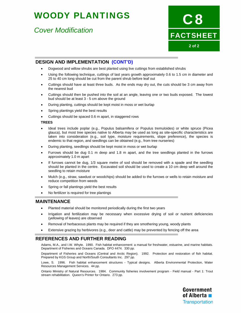
FACTSHEET
C82 of 2
WOODY PLANTINGS
Cover Modification
DESIGN AND IMPLEMENTATION (CONT’D) • Dogwood and willow shrubs are best planted using live cuttings from established shrubs
• Using the following technique, cuttings of last years growth approximately 0.6 to 1.5 cm in diameter and 25 to 40 cm long should be cut from the parent shrub before leaf out
• Cuttings should have at least three buds. As the ends may dry out, the cuts should be 3 cm away from the nearest bud
• Cuttings should then be pushed into the soil at an angle, leaving one or two buds exposed. The lowest bud should be at least 3 - 5 cm above the ground
• During planting, cuttings should be kept moist in moss or wet burlap
• Spring plantings yield the best results
• Cuttings should be spaced 0.6 m apart, in staggered rows TREES • Ideal trees include poplar (e.g., Populus balsamifera or Populus tremuloides) or white spruce (Picea
glauca), but most tree species native to Alberta may be used as long as site-specific characteristics are taken into consideration (e.g., soil type, moisture requirements, slope preference), the species is endemic to that region, and seedlings can be obtained (e.g., from tree nurseries)
• During planting, seedlings should be kept moist in moss or wet burlap
• Furrows should be dug 0.1 m deep and 1.8 m apart, and the tree seedlings planted in the furrows approximately 1.0 m apart
• If furrows cannot be dug, 1/3 square metre of sod should be removed with a spade and the seedling should be planted in the centre. Excavated soil should be used to create a 10 cm deep well around the seedling to retain moisture
• Mulch (e.g., straw, sawdust or woodchips) should be added to the furrows or wells to retain moisture and reduce competition from weeds
• Spring or fall plantings yield the best results
• No fertilizer is required for tree plantings
MAINTENANCE • Planted material should be monitored periodically during the first two years
• Irrigation and fertilization may be necessary when excessive drying of soil or nutrient deficiencies (yellowing of leaves) are observed
• Removal of herbaceous plants may be required if they are smothering young, woody plants
• Extensive grazing by herbivores (e.g., deer and cattle) may be prevented by fencing off the area
REFERENCES AND FURTHER READING Adams, M.A., and I.W. Whyte. 1990. Fish habitat enhancement: a manual for freshwater, estuarine, and marine habitats. Department of Fisheries and Oceans Canada. DFO 4474. 330 pp. Department of Fisheries and Oceans (Central and Arctic Region). 1992. Protection and restoration of fish habitat. Prepared by KGS Group and North/South Consultants Inc. 297 pp. Lowe, S. 1996. Fish habitat enhancement structures - Typical designs. Alberta Environmental Protection, Water Resources Management Services. 44 pp. Ontario Ministry of Natural Resources. 1984. Community fisheries involvement program - Field manual - Part 1: Trout stream rehabilitation. Queen’s Printer for Ontario. 273 pp.
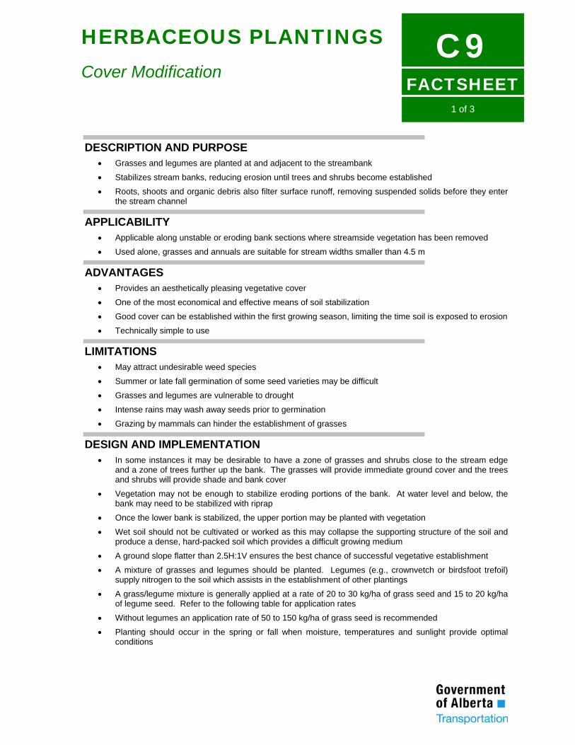
FACTSHEET
C91 of 3
HERBACEOUS PLANTINGS
Cover Modification
DESCRIPTION AND PURPOSE • Grasses and legumes are planted at and adjacent to the streambank
• Stabilizes stream banks, reducing erosion until trees and shrubs become established
• Roots, shoots and organic debris also filter surface runoff, removing suspended solids before they enter the stream channel
APPLICABILITY • Applicable along unstable or eroding bank sections where streamside vegetation has been removed
• Used alone, grasses and annuals are suitable for stream widths smaller than 4.5 m
ADVANTAGES • Provides an aesthetically pleasing vegetative cover
• One of the most economical and effective means of soil stabilization
• Good cover can be established within the first growing season, limiting the time soil is exposed to erosion
• Technically simple to use
LIMITATIONS • May attract undesirable weed species
• Summer or late fall germination of some seed varieties may be difficult
• Grasses and legumes are vulnerable to drought
• Intense rains may wash away seeds prior to germination
• Grazing by mammals can hinder the establishment of grasses
DESIGN AND IMPLEMENTATION • In some instances it may be desirable to have a zone of grasses and shrubs close to the stream edge
and a zone of trees further up the bank. The grasses will provide immediate ground cover and the trees and shrubs will provide shade and bank cover
• Vegetation may not be enough to stabilize eroding portions of the bank. At water level and below, the bank may need to be stabilized with riprap
• Once the lower bank is stabilized, the upper portion may be planted with vegetation
• Wet soil should not be cultivated or worked as this may collapse the supporting structure of the soil and produce a dense, hard-packed soil which provides a difficult growing medium
• A ground slope flatter than 2.5H:1V ensures the best chance of successful vegetative establishment
• A mixture of grasses and legumes should be planted. Legumes (e.g., crownvetch or birdsfoot trefoil) supply nitrogen to the soil which assists in the establishment of other plantings
• A grass/legume mixture is generally applied at a rate of 20 to 30 kg/ha of grass seed and 15 to 20 kg/ha of legume seed. Refer to the following table for application rates
• Without legumes an application rate of 50 to 150 kg/ha of grass seed is recommended
• Planting should occur in the spring or fall when moisture, temperatures and sunlight provide optimal conditions
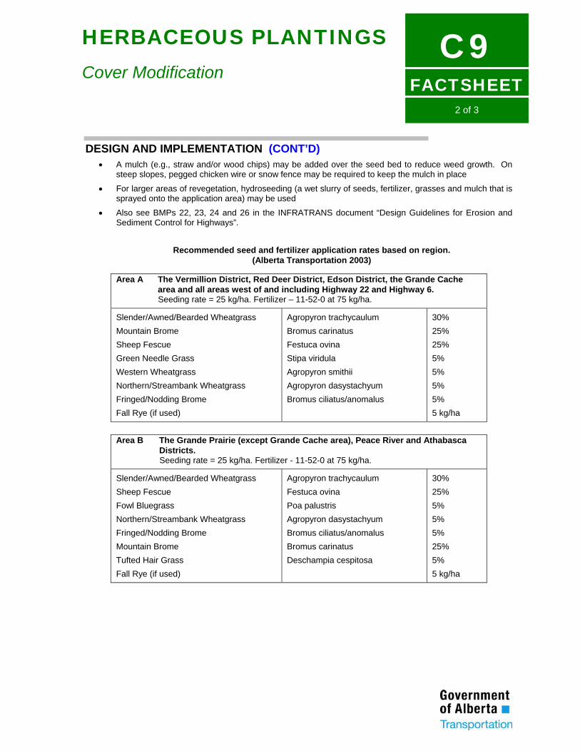
FACTSHEET
C92 of 3
HERBACEOUS PLANTINGS
Cover Modification
DESIGN AND IMPLEMENTATION (CONT’D) • A mulch (e.g., straw and/or wood chips) may be added over the seed bed to reduce weed growth. On
steep slopes, pegged chicken wire or snow fence may be required to keep the mulch in place
• For larger areas of revegetation, hydroseeding (a wet slurry of seeds, fertilizer, grasses and mulch that is sprayed onto the application area) may be used
• Also see BMPs 22, 23, 24 and 26 in the INFRATRANS document “Design Guidelines for Erosion and Sediment Control for Highways”.
Recommended seed and fertilizer application rates based on region.
(Alberta Transportation 2003)
Area A The Vermillion District, Red Deer District, Edson District, the Grande Cache area and all areas west of and including Highway 22 and Highway 6. Seeding rate = 25 kg/ha. Fertilizer – 11-52-0 at 75 kg/ha.
Slender/Awned/Bearded Wheatgrass Mountain Brome Sheep Fescue Green Needle Grass Western Wheatgrass Northern/Streambank Wheatgrass Fringed/Nodding Brome Fall Rye (if used)
Agropyron trachycaulum Bromus carinatus Festuca ovina Stipa viridula Agropyron smithii Agropyron dasystachyum Bromus ciliatus/anomalus
30% 25% 25% 5% 5% 5% 5% 5 kg/ha
Area B The Grande Prairie (except Grande Cache area), Peace River and Athabasca Districts. Seeding rate = 25 kg/ha. Fertilizer - 11-52-0 at 75 kg/ha.
Slender/Awned/Bearded Wheatgrass Sheep Fescue Fowl Bluegrass Northern/Streambank Wheatgrass Fringed/Nodding Brome Mountain Brome Tufted Hair Grass Fall Rye (if used)
Agropyron trachycaulum Festuca ovina Poa palustris Agropyron dasystachyum Bromus ciliatus/anomalus Bromus carinatus Deschampia cespitosa
30% 25% 5% 5% 5% 25% 5% 5 kg/ha
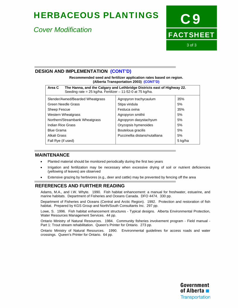
FACTSHEET
C93 of 3
HERBACEOUS PLANTINGS
Cover Modification
DESIGN AND IMPLEMENTATION (CONT’D) Recommended seed and fertilizer application rates based on region.
(Alberta Transportation 2003) (CONT’D) Area C The Hanna, and the Calgary and Lethbridge Districts east of Highway 22.
Seeding rate = 25 kg/ha. Fertilizer – 11-52-0 at 75 kg/ha.
Slender/Awned/Bearded Wheatgrass Green Needle Grass Sheep Fescue Western Wheatgrass Northern/Streambank Wheatgrass Indian Rice Grass Blue Grama Alkali Grass Fall Rye (if used)
Agropyron trachycaulum Stipa viridula Festuca ovina Agropyron smithii Agropyron dasystachyum Oryzopsis hymenoides Bouteloua gracilis Puccinellia distans/nutalliana
35% 5% 35% 5% 5% 5% 5% 5% 5 kg/ha
MAINTENANCE • Planted material should be monitored periodically during the first two years
• Irrigation and fertilization may be necessary when excessive drying of soil or nutrient deficiencies (yellowing of leaves) are observed
• Extensive grazing by herbivores (e.g., deer and cattle) may be prevented by fencing off the area
REFERENCES AND FURTHER READING Adams, M.A., and I.W. Whyte. 1990. Fish habitat enhancement: a manual for freshwater, estuarine, and marine habitats. Department of Fisheries and Oceans Canada. DFO 4474. 330 pp. Department of Fisheries and Oceans (Central and Arctic Region). 1992. Protection and restoration of fish habitat. Prepared by KGS Group and North/South Consultants Inc. 297 pp. Lowe, S. 1996. Fish habitat enhancement structures - Typical designs. Alberta Environmental Protection, Water Resources Management Services. 44 pp. Ontario Ministry of Natural Resources. 1984. Community fisheries involvement program - Field manual - Part 1: Trout stream rehabilitation. Queen’s Printer for Ontario. 273 pp. Ontario Ministry of Natural Resources. 1990. Environmental guidelines for access roads and water crossings. Queen’s Printer for Ontario. 64 pp.
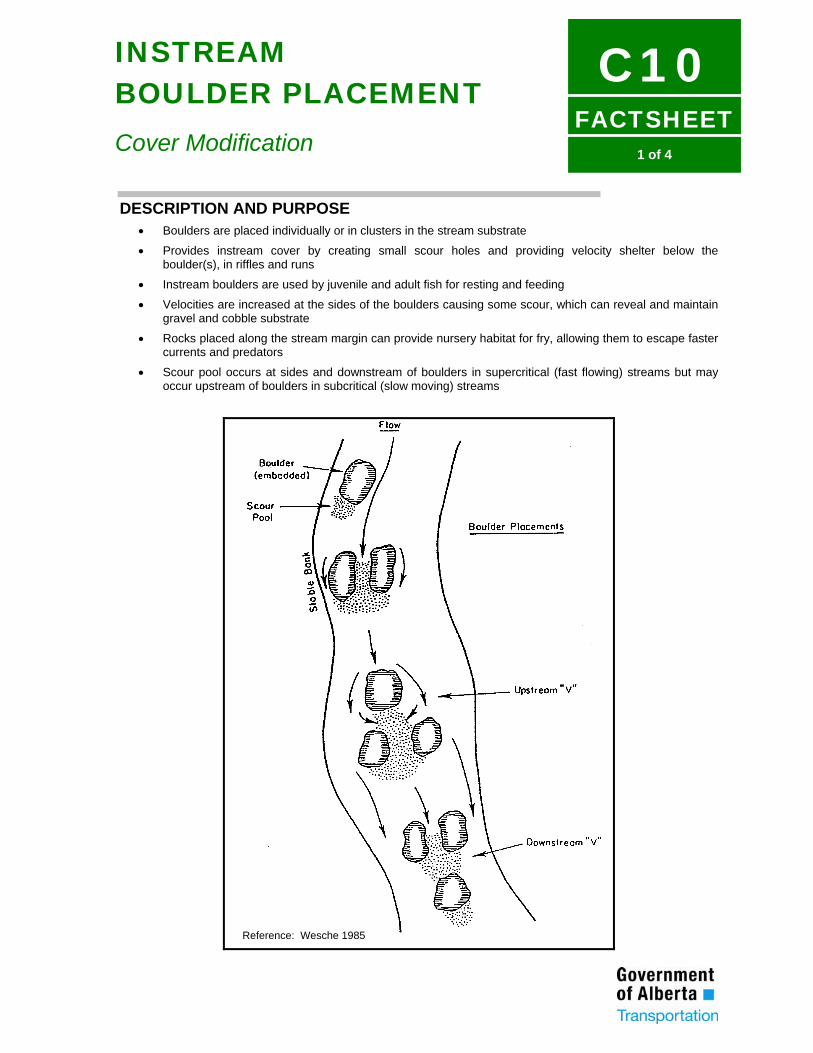
FACTSHEET
C101 of 4
INSTREAM BOULDER PLACEMENT
Cover Modification
DESCRIPTION AND PURPOSE • Boulders are placed individually or in clusters in the stream substrate
• Provides instream cover by creating small scour holes and providing velocity shelter below the boulder(s), in riffles and runs
• Instream boulders are used by juvenile and adult fish for resting and feeding
• Velocities are increased at the sides of the boulders causing some scour, which can reveal and maintain gravel and cobble substrate
• Rocks placed along the stream margin can provide nursery habitat for fry, allowing them to escape faster currents and predators
• Scour pool occurs at sides and downstream of boulders in supercritical (fast flowing) streams but may occur upstream of boulders in subcritical (slow moving) streams
Reference: Wesche 1985

FACTSHEET
C102 of 4
INSTREAM BOULDER PLACEMENT
Cover Modification
APPLICABILITY • Boulders are generally placed in riffles, glides and shallower runs although they may also be used in
deeper pools and runs
• Boulder placement is best suited for moderate-gradient streams and rivers, with a substrate of cobble and gravel and moderate to high sinuosity and width to depth ratio
ADVANTAGES • Boulder placement is a simple way to increase instream fish cover
• Cost-effective, particularly if the boulders may be obtained from the local area (e.g., from the cleared right-of-way)
LIMITATIONS • Unsuitable for substrate which is predominantly bedrock, sand or clay
• May interfere with navigation
• Improperly placed boulders may cause bank erosion
• Not recommended for streams which are aggrading or degrading
• May promote bar formation upstream and downstream of the boulders in streams with high bedload transport
• In streams with unstable sand bottoms, boulders may shift or be buried
• Not suitable for watercourses with severe ice scour or flooding
• Most appropriate for water velocities greater than 0.6 m/s. Flood velocities should not exceed 2.4 m/s
• Heavy equipment may be required for installation
DESIGN AND IMPLEMENTATION (REFER TO FIGURE) • Boulders may be placed singly (suited for very small streams) or in clusters in larger streams and rivers.
Boulders are commonly placed in clusters of three in a downward or upward pointing triangular configuration
• Minimum rock size is dependent on maximum velocities, but 60 to 90 cm diameter boulders are commonly used
• Placement in straight, wide, shallow sections of streams with stable banks is recommended
• Boulder clusters are most effective at providing habitat for larger fish
• To provide habitat for fry, scattered rock should be used
BOULDER CLUSTERS • Angular boulders should be placed in groups of three, in the middle 3/4 of the stream, in a pattern so that
the boulders do not direct the current to a bank
• Boulders placed singly in large streams provide little cover for fish
• Boulders should be placed in pre-excavated holes so that they do no not protrude above the water surface by more than 0.3 m at low flow
• Within the clusters, each boulder should be spaced 0.8 to 1.5 m from each other. Clusters should be placed a minimum of 2.5 m from other clusters
• No more than 20% of the stream width should be obstructed at any given point
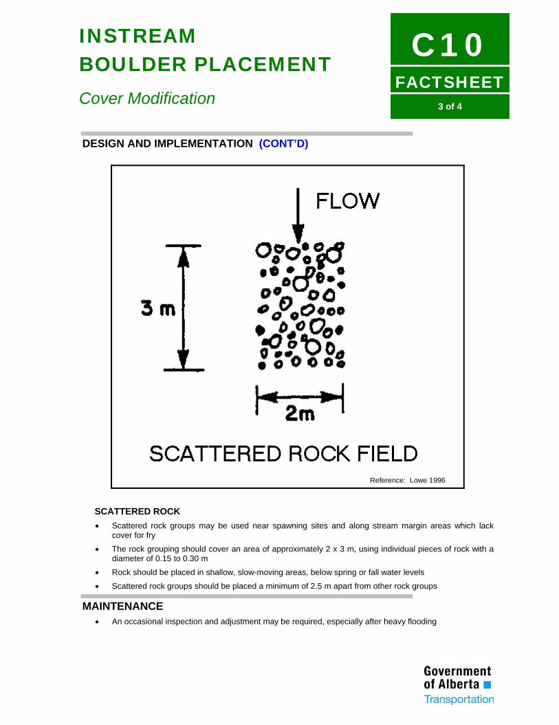
FACTSHEET
C103 of 4
INSTREAM BOULDER PLACEMENT
Cover Modification
DESIGN AND IMPLEMENTATION (CONT’D)
SCATTERED ROCK • Scattered rock groups may be used near spawning sites and along stream margin areas which lack
cover for fry
• The rock grouping should cover an area of approximately 2 x 3 m, using individual pieces of rock with a diameter of 0.15 to 0.30 m
• Rock should be placed in shallow, slow-moving areas, below spring or fall water levels
• Scattered rock groups should be placed a minimum of 2.5 m apart from other rock groups
MAINTENANCE • An occasional inspection and adjustment may be required, especially after heavy flooding
Reference: Lowe 1996
FACTSHEET
C104 of 4
INSTREAM BOULDER PLACEMENT
Cover Modification
REFERENCES AND FURTHER READING Department of Fisheries and Oceans (Central and Arctic Region). 1992. Protection and restoration of fish habitat. Prepared by KGS Group and North/South Consultants Inc. 297 pp. Federal Interagency Stream Restoration Working Group (15 agencies). 1998. Stream corridor restoration - Principles, processes, and practices. United States Department of Agriculture. 519 pp. Lowe, S. 1996. Fish habitat enhancement structures - Typical designs. Alberta Environmental Protection, Water Resources Management Services. 44 pp. Rosgen, D. 1996. Applied river morphology. Wildland Hydrology, Pagosa Springs, Colorado. 336 pp. Shuler, S.W., R.B. Nehring, and K.D. Fausch. 1994. Diel habitat selection by brown trout in the Rio Grande River, Colorado, after placement of boulder structures. North American Journal of Fisheries Management 14: 99-111. Wetche, T.A. 1985. Stream channel modifications and reclamation structures to enhance fish habitat. pp 103-163 in J.A. Gore, editor. The restoration of rivers and streams - theories and experience. Ann Arbor Science. 280 pp.
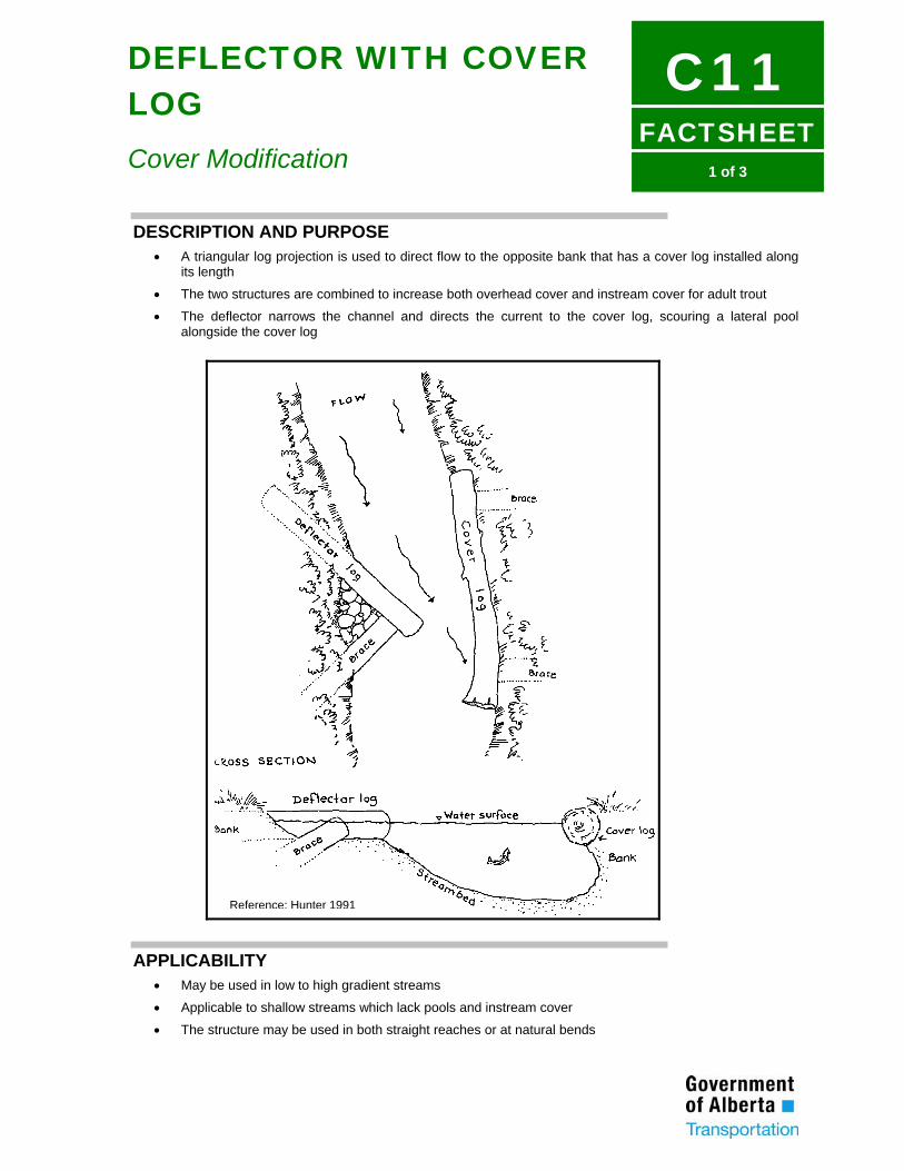
FACTSHEET
C111 of 3
DEFLECTOR WITH COVER LOG
Cover Modification
DESCRIPTION AND PURPOSE • A triangular log projection is used to direct flow to the opposite bank that has a cover log installed along
its length
• The two structures are combined to increase both overhead cover and instream cover for adult trout
• The deflector narrows the channel and directs the current to the cover log, scouring a lateral pool alongside the cover log
APPLICABILITY • May be used in low to high gradient streams
• Applicable to shallow streams which lack pools and instream cover
• The structure may be used in both straight reaches or at natural bends
Reference: Hunter 1991
FACTSHEET
C112 of 3
DEFLECTOR WITH COVER LOG
Cover Modification
ADVANTAGES • May be assembled from conifer trees from the local area
• Produces a natural appearance which maintains the aesthetics of the stream
• Requires little maintenance
LIMITATIONS • Suitable for streams less than 6 m wide
• Heavy equipment may be required for construction, depending on the size of the logs used
• Unsuitable for bedrock streams
DESIGN AND IMPLEMENTATION (REFER TO FIGURE) • The apex of the log deflector should narrow the stream by 40 to 80%
• The deflector should be built using 0.36 to 0.50 m diameter logs. The length of the logs depends on the stream width and the angles of installation
• Where only smaller logs are available, one log may be pinned on top of another in order to achieve the proper height
• The deflector log should be placed at an angle of 40 to 45o to the stream flow and the brace log should be pinned to the deflector at an angle of 90o
• The two logs should be laid in 10 cm deep trenches, with the ends extended 2 m into the bank
• The deflector log should be pinned to the brace log with 0.6 m of 15 mm rebar. 1.5 m lengths of rebar should be driven through the both logs to anchor them into the substrate
• The deflector should extend 0.15 to 0.30 m above normal summer flow levels
• The triangular area within the deflector should be filled with larger boulders, flush with the top of the deflector
• Topsoil should be placed on the surface of the boulders and seeded to provide a natural appearance
• The cover log should be of a similar diameter to that of the deflector and approximately 1.5 times the length of the deflector log
• To increase instream cover, 0.6 m long sections along the underside of the cover log may be partially notched out
• The log deflector should be situated so the apex directs the flow towards the lower third of the cover log. This will create a scour pool along the upper two-thirds of the cover log
• Two brace logs, each 2 m in length, should be pinned to the cover log using 0.6 m lengths of 15 mm rebar. The brace logs should be fully buried in the bank
• The brace logs should be secured by driving 1.5 m lengths of 15 mm rebar through them into the ground
• The cover log should be angled slightly into the direction of the flow to keep the area below the cover log scoured and free of sediments. Alternatively a cover log which flares out slightly at the downstream base may be used
• The cover log should extend 0.15 - 0.30 m above normal summer flows
FACTSHEET
C113 of 3
DEFLECTOR WITH COVER LOG
Cover Modification
MAINTENANCE • These structures should be monitored periodically after construction, particularly in the first year after
high flows
• Streambanks downstream of each structure should be checked for erosion and armoured with riprap if required
• The structures may require eventual replacement when the wood rots
REFERENCES AND FURTHER READING Hunt, R.L. 1993. Trout stream therapy. The University of Wisconsin Press. 74 pp. Hunter, C.J. 1991. Better trout habitat - A guide to stream restoration and management. Island Press, Washington, D.C. 320 pp
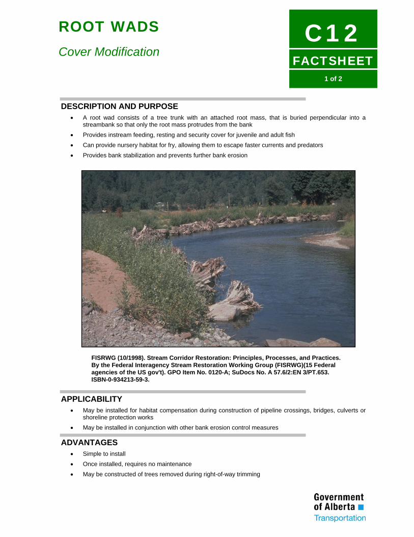
FACTSHEET
C121 of 2
ROOT WADS
Cover Modification
DESCRIPTION AND PURPOSE • A root wad consists of a tree trunk with an attached root mass, that is buried perpendicular into a
streambank so that only the root mass protrudes from the bank
• Provides instream feeding, resting and security cover for juvenile and adult fish
• Can provide nursery habitat for fry, allowing them to escape faster currents and predators
• Provides bank stabilization and prevents further bank erosion
FISRWG (10/1998). Stream Corridor Restoration: Principles, Processes, and Practices. By the Federal Interagency Stream Restoration Working Group (FISRWG)(15 Federal agencies of the US gov't). GPO Item No. 0120-A; SuDocs No. A 57.6/2:EN 3/PT.653. ISBN-0-934213-59-3.
APPLICABILITY • May be installed for habitat compensation during construction of pipeline crossings, bridges, culverts or
shoreline protection works
• May be installed in conjunction with other bank erosion control measures
ADVANTAGES • Simple to install
• Once installed, requires no maintenance
• May be constructed of trees removed during right-of-way trimming
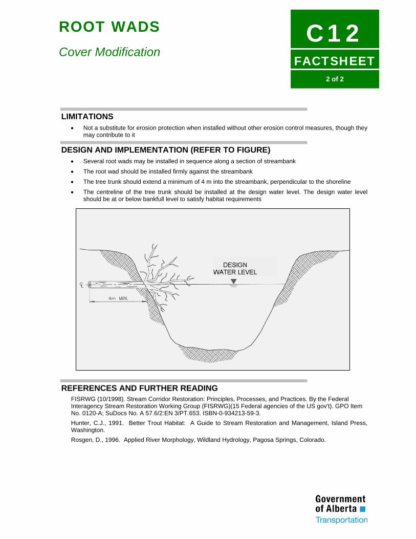
FACTSHEET
C122 of 2
ROOT WADS
Cover Modification
LIMITATIONS • Not a substitute for erosion protection when installed without other erosion control measures, though they
may contribute to it
DESIGN AND IMPLEMENTATION (REFER TO FIGURE) • Several root wads may be installed in sequence along a section of streambank
• The root wad should be installed firmly against the streambank
• The tree trunk should extend a minimum of 4 m into the streambank, perpendicular to the shoreline
• The centreline of the tree trunk should be installed at the design water level. The design water level should be at or below bankfull level to satisfy habitat requirements
REFERENCES AND FURTHER READING FISRWG (10/1998). Stream Corridor Restoration: Principles, Processes, and Practices. By the Federal Interagency Stream Restoration Working Group (FISRWG)(15 Federal agencies of the US gov't). GPO Item No. 0120-A; SuDocs No. A 57.6/2:EN 3/PT.653. ISBN-0-934213-59-3. Hunter, C.J., 1991. Better Trout Habitat: A Guide to Stream Restoration and Management, Island Press, Washington. Rosgen, D., 1996. Applied River Morphology, Wildland Hydrology, Pagosa Springs, Colorado.
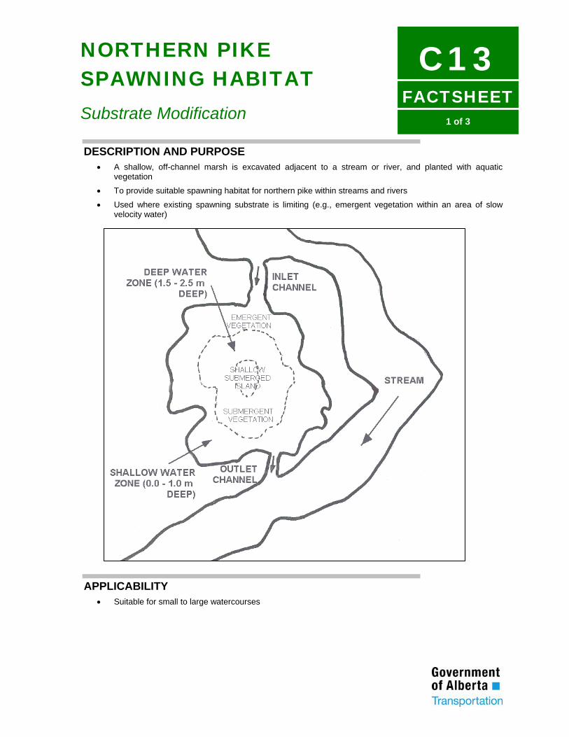
FACTSHEET
C131 of 3
NORTHERN PIKE SPAWNING HABITAT
Substrate Modification
DESCRIPTION AND PURPOSE • A shallow, off-channel marsh is excavated adjacent to a stream or river, and planted with aquatic
vegetation
• To provide suitable spawning habitat for northern pike within streams and rivers
• Used where existing spawning substrate is limiting (e.g., emergent vegetation within an area of slow velocity water)
APPLICABILITY • Suitable for small to large watercourses
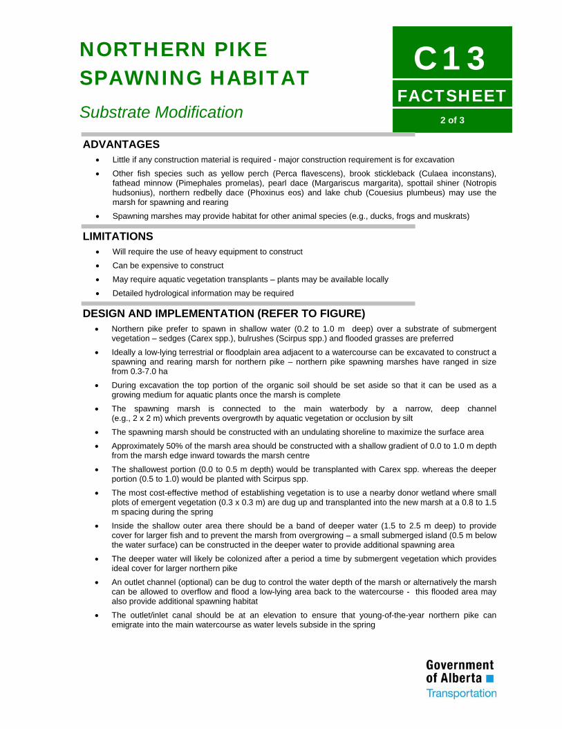
FACTSHEET
C132 of 3
NORTHERN PIKE SPAWNING HABITAT
Substrate Modification ADVANTAGES
• Little if any construction material is required - major construction requirement is for excavation
• Other fish species such as yellow perch (Perca flavescens), brook stickleback (Culaea inconstans), fathead minnow (Pimephales promelas), pearl dace (Margariscus margarita), spottail shiner (Notropis hudsonius), northern redbelly dace (Phoxinus eos) and lake chub (Couesius plumbeus) may use the marsh for spawning and rearing
• Spawning marshes may provide habitat for other animal species (e.g., ducks, frogs and muskrats)
LIMITATIONS • Will require the use of heavy equipment to construct
• Can be expensive to construct
• May require aquatic vegetation transplants – plants may be available locally
• Detailed hydrological information may be required
DESIGN AND IMPLEMENTATION (REFER TO FIGURE) • Northern pike prefer to spawn in shallow water (0.2 to 1.0 m deep) over a substrate of submergent
vegetation – sedges (Carex spp.), bulrushes (Scirpus spp.) and flooded grasses are preferred
• Ideally a low-lying terrestrial or floodplain area adjacent to a watercourse can be excavated to construct a spawning and rearing marsh for northern pike – northern pike spawning marshes have ranged in size from 0.3-7.0 ha
• During excavation the top portion of the organic soil should be set aside so that it can be used as a growing medium for aquatic plants once the marsh is complete
• The spawning marsh is connected to the main waterbody by a narrow, deep channel (e.g., 2 x 2 m) which prevents overgrowth by aquatic vegetation or occlusion by silt
• The spawning marsh should be constructed with an undulating shoreline to maximize the surface area
• Approximately 50% of the marsh area should be constructed with a shallow gradient of 0.0 to 1.0 m depth from the marsh edge inward towards the marsh centre
• The shallowest portion (0.0 to 0.5 m depth) would be transplanted with Carex spp. whereas the deeper portion (0.5 to 1.0) would be planted with Scirpus spp.
• The most cost-effective method of establishing vegetation is to use a nearby donor wetland where small plots of emergent vegetation (0.3 x 0.3 m) are dug up and transplanted into the new marsh at a 0.8 to 1.5 m spacing during the spring
• Inside the shallow outer area there should be a band of deeper water (1.5 to 2.5 m deep) to provide cover for larger fish and to prevent the marsh from overgrowing – a small submerged island (0.5 m below the water surface) can be constructed in the deeper water to provide additional spawning area
• The deeper water will likely be colonized after a period a time by submergent vegetation which provides ideal cover for larger northern pike
• An outlet channel (optional) can be dug to control the water depth of the marsh or alternatively the marsh can be allowed to overflow and flood a low-lying area back to the watercourse - this flooded area may also provide additional spawning habitat
• The outlet/inlet canal should be at an elevation to ensure that young-of-the-year northern pike can emigrate into the main watercourse as water levels subside in the spring
FACTSHEET
C133 of 3
NORTHERN PIKE SPAWNING HABITAT
Substrate Modification MAINTENANCE
• An inspection should be completed once every several years
• If the marsh becomes overgrown with shrubs and trees they should be removed
• Should the shallow area of the marsh become overgrown with aquatic vegetation and shallower, the area may have to be re-excavated to design specifications
• Monitoring should be completed after construction to determine if northern pike are using marsh for spawning
REFERENCES AND FURTHER READING Casselman, J.M., and C.A. Lewis. 1996. Habitat requirements of northern pike. Canadian Journal of Fisheries and Aquatic Science 53 (Suppl. 1): 161-174. Cott, P. A. 2004. Nohern pike (Esox lucius) habitat enhancement in the Northwest Territories. Canadian Technical Report of Fisheries and Aquatic Science 2528: vii + 32 p. Kelso, J.R.M., and Hartig, J.H. 1995. Methods of modifying habitat to benefit the Great Lakes ecosystem. CISTI Occasional Paper 1: 294 pp. Hammer, D.A. 1992. Creating freshwater wetlands. Lewis Publishers. 298 pp. Morrow, J.V., G.L. Miller, and K.J. Killgore. 1997. Density, size, and foods of larval northern pike in natural and artificial wetlands. North American Journal of Fisheries Management 17: 210-214.
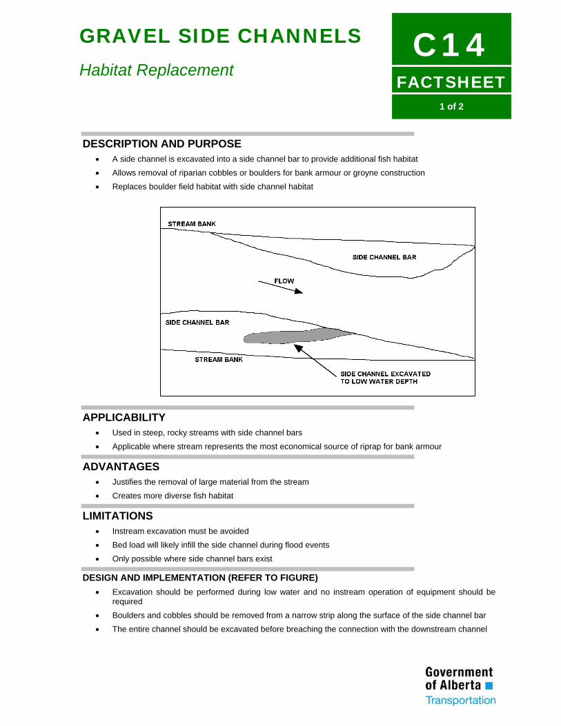
FACTSHEET
C141 of 2
GRAVEL SIDE CHANNELS
Habitat Replacement
DESCRIPTION AND PURPOSE • A side channel is excavated into a side channel bar to provide additional fish habitat
• Allows removal of riparian cobbles or boulders for bank armour or groyne construction
• Replaces boulder field habitat with side channel habitat
APPLICABILITY • Used in steep, rocky streams with side channel bars
• Applicable where stream represents the most economical source of riprap for bank armour
ADVANTAGES • Justifies the removal of large material from the stream
• Creates more diverse fish habitat
LIMITATIONS • Instream excavation must be avoided
• Bed load will likely infill the side channel during flood events
• Only possible where side channel bars exist
DESIGN AND IMPLEMENTATION (REFER TO FIGURE) • Excavation should be performed during low water and no instream operation of equipment should be
required
• Boulders and cobbles should be removed from a narrow strip along the surface of the side channel bar
• The entire channel should be excavated before breaching the connection with the downstream channel
FACTSHEET
C142 of 2
GRAVEL SIDE CHANNELS
Habitat Replacement
• The side channel should not be excavated below the elevation of water in the channel during
construction
MAINTENANCE • The side channel may fill with bed load during flood events. If continued maintenance of the side
channel is desired, the infilled material may be removed during low water
FACTSHEET
C151 of 2
SHORELINE DIVERSITY
Habitat Replacement
DESCRIPTION AND PURPOSE • Provide a variety of habitat features within a given area
• Shoreline habitat diversity encourages diversity of fish species
APPLICABILITY • Used to restore habitat (mitigation) or to create or enhance off-site habitat (compensation)
• Structure layout, armour placement and bioengineering measures can all contribute to shoreline diversity
ADVANTAGES • Healthy fish communities tend to exist in healthy dynamically stable channel systems. Such systems
provide the correct mix of habitat features: pools, riffles, bed materials, bank features, aquatic and stream bank vegetation, woody debris, etc. that provide for the basic life requisites of food, reproduction and cover
LIMITATIONS • Habitat features should be tailored to suit resident fish communities
DESIGN AND IMPLEMENTATION • Design of shoreline areas should incorporate a variety of habitat features
• Erosion control structures such as rock riprap, gabions or groynes and spurs, can contribute to habitat diversity by creating variations in flow depth and velocity. Rock sizes can be specified to provide refugia or spawning habitat
• Substrate modifications, cover modifications or habitat replacements can be incorporated into designs to provide habitat targeted at specific fish species or communities
MAINTENANCE • Follow maintenance recommendations for specific compensation and mitigation measures
REFERENCES AND FURTHER READING Hunter, C.J., 1991. Better Trout Habitat: A Guide to Stream Restoration and Management, Island Press, Washington. Rosgen, D., 1996. Applied River Morphology, Wildland Hydrology, Pagosa Springs, Colorado.
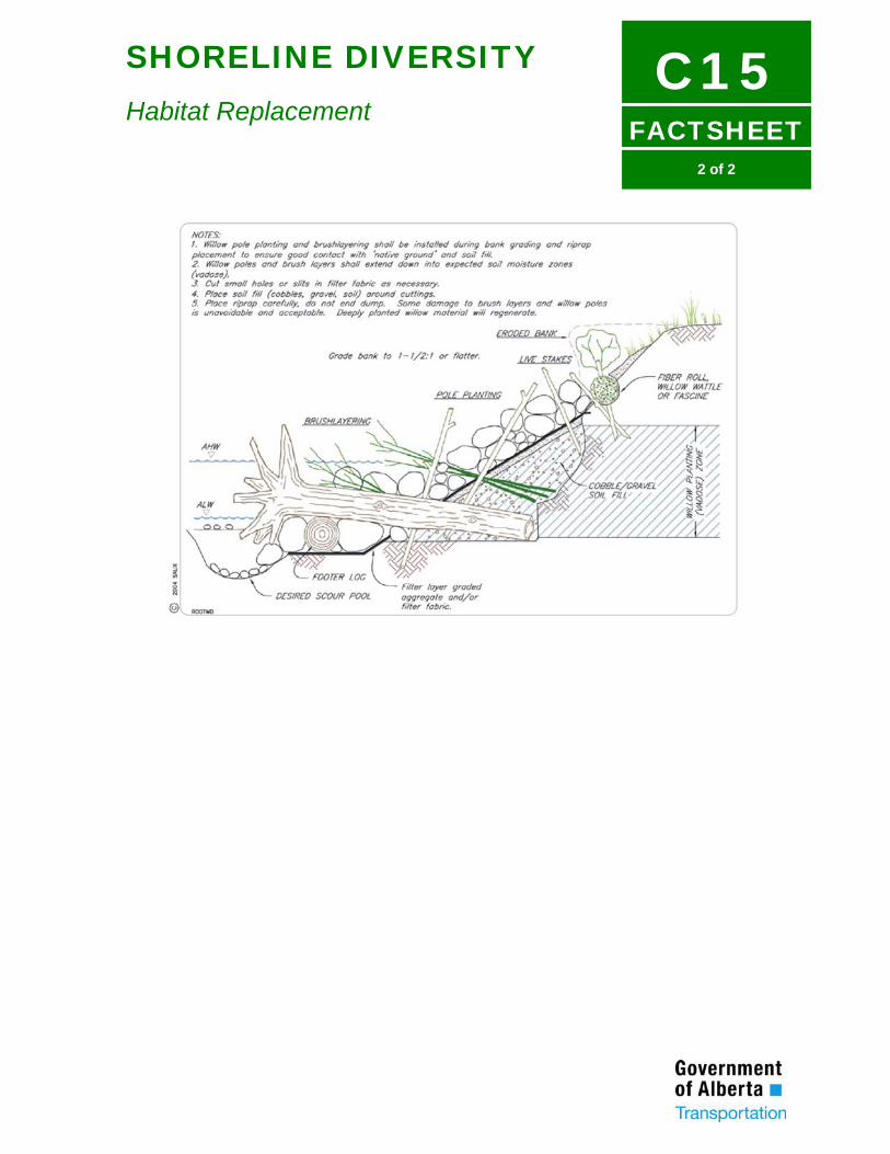
FACTSHEET
C152 of 2
SHORELINE DIVERSITY
Habitat Replacement