Embed Size (px)
Citation preview
Complete Clinical Orthodontics
© 2010 Antonino G. Secchi, DMD, MS
Antonino G. Secchi, DMD, MS
Course Manual
- M e c h a n i c s -
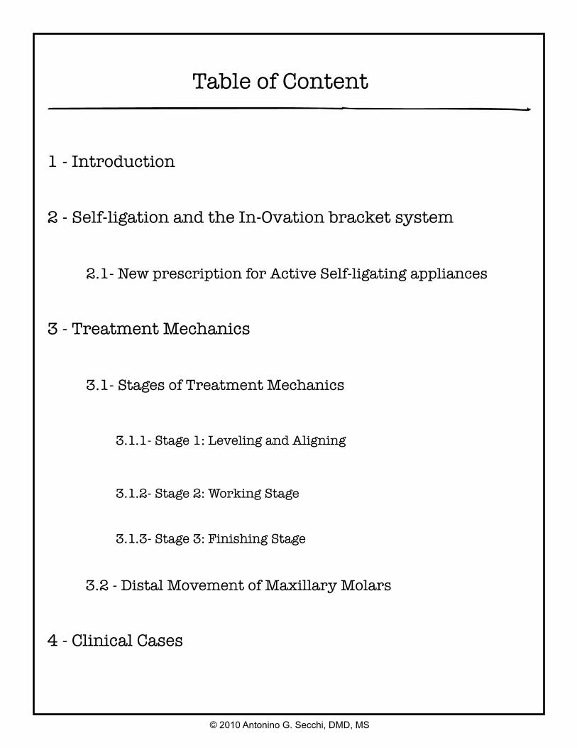
Table of Content
1 - Introduction
2 - Self-ligation and the In-Ovation bracket system
2.1- New prescription for Active Self-ligating appliances
3 - Treatment Mechanics
3.1- Stages of Treatment Mechanics
3.1.1- Stage 1: Leveling and Aligning
3.1.2- Stage 2: Working Stage
3.1.3- Stage 3: Finishing Stage
3.2 - Distal Movement of Maxillary Molars
4 - Clinical Cases
© 2010 Antonino G. Secchi, DMD, MS
Introduction
Treatment mechanics has always been of tremendous interest for all practicing orthodontists. Since the beginning of our specialty, we have looked for the best, fastest, more consistent and easiest way to achieve the orthodontic correction for our patients. This continuos quest have allowed emerging technologies to integrate, although slowly sometimes, with our everyday practice until they become a routine. Thus, as a consequence, new materials, improvement in design of appliances and innovative ideas repeatedly transform the way we practice. It is important for the contemporary orthodontist to be knowledgeable of current changes, so to take the best of them.
Today, after the first decade of the 21st century has already passed, orthodontic fixed appliances have experienced an interesting blend between technologies that have been around for decades such as the Straight Wire Appliance (SWA), self - ligation and low deflection thermal-activated archwires. This integration, in my opinion, represents an improvement that, when correctly applied, facilitates the practice of orthodontics.
In this manual the reader will find the author’s interpretation of how the SWA integrates with self-ligation and how this appliance, with the combination of a specific archwire sequence can help the orthodontist to correct different types of malocclusions in the adult dentition. Relevant characteristics of active self-ligating appliances, a modified prescription along with a specific wire sequence for different orthodontic scenarios are among the areas covered.
To facilitate the understanding of the mechanics utilized in different situations, 10 cases “step by step” were included at the end of the manual. Type of appliances, wire sequence and any auxiliary used are specified. I selected these cases because I think they depict “everyday” problems we face in our practices.
© 2010 Antonino G. Secchi, DMD, MS
1
Self-Ligation and The In-Ovation Bracket System
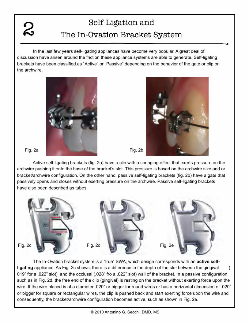
In the last few years self-ligating appliances have become very popular. A great deal of discussion have arisen around the friction these appliance systems are able to generate. Self-ligating brackets have been classified as “Active” or “Passive” depending on the behavior of the gate or clip on the archwire.
Active self-ligating brackets (fig. 2a) have a clip with a springing effect that exerts pressure on the archwire pushing it onto the base of the bracket’s slot. This pressure is based on the archwire size and or bracket/archwire configuration. On the other hand, passive self-ligating brackets (fig. 2b) have a gate that passively opens and closes without exerting pressure on the archwire. Passive self-ligating brackets have also been described as tubes.
Fig. 2a Fig. 2b
The In-Ovation bracket system is a “true” SWA, which design corresponds with an active self-ligating appliance. As Fig. 2c shows, there is a difference in the depth of the slot between the gingival (.019” for a .022” slot) and the occlusal (.028” fro a .022” slot) wall of the bracket. In a passive configuration such as in Fig. 2d, the free end of the clip (gingival) is resting on the bracket without exerting force upon the wire. If the wire placed is of a diameter .020” or bigger for round wires or has a horizontal dimension of .020” or bigger for square or rectangular wires, the clip is pushed back and start exerting force upon the wire and consequently, the bracket/archwire configuration becomes active, such as shown in Fig. 2e.
Fig. 2c Fig. 2d Fig. 2e
© 2010 Antonino G. Secchi, DMD, MS
2
© 2010 Antonino G. Secchi, DMD, MS
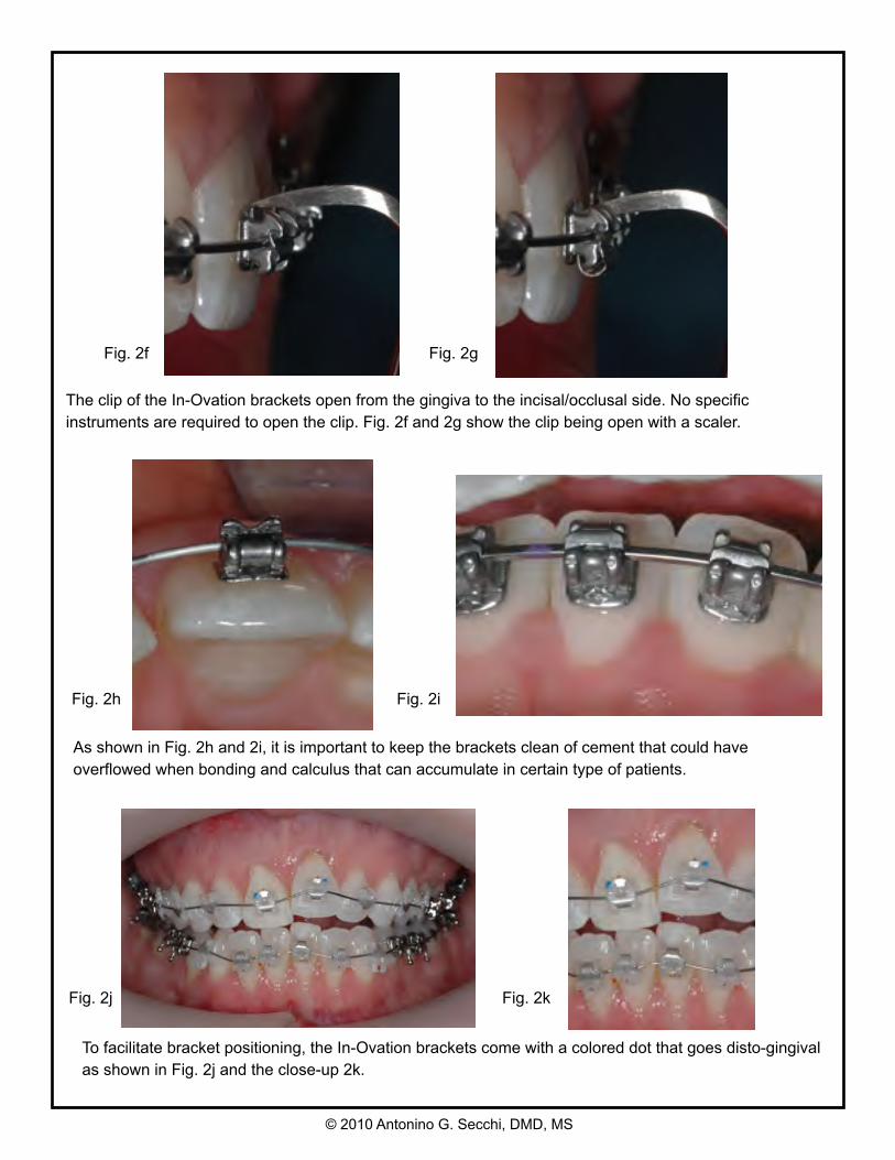
As shown in Fig. 2h and 2i, it is important to keep the brackets clean of cement that could have overflowed when bonding and calculus that can accumulate in certain type of patients.
The clip of the In-Ovation brackets open from the gingiva to the incisal/occlusal side. No specific instruments are required to open the clip. Fig. 2f and 2g show the clip being open with a scaler.
To facilitate bracket positioning, the In-Ovation brackets come with a colored dot that goes disto-gingival as shown in Fig. 2j and the close-up 2k.
444
Fig. 2f Fig. 2g
Fig. 2h Fig. 2i
Fig. 2j Fig. 2k
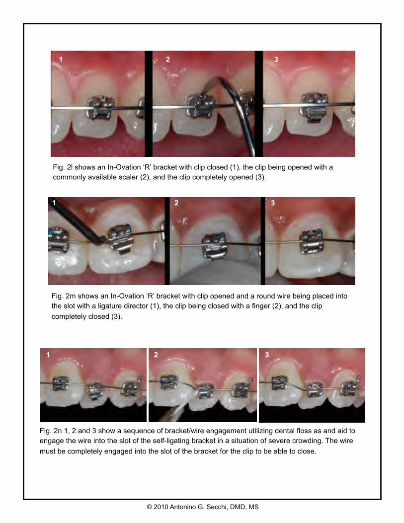
Fig. 2l shows an In-Ovation ‘R’ bracket with clip closed (1), the clip being opened with a commonly available scaler (2), and the clip completely opened (3).
1 2 3
1 2 3
Fig. 2m shows an In-Ovation ‘R’ bracket with clip opened and a round wire being placed into the slot with a ligature director (1), the clip being closed with a finger (2), and the clip completely closed (3).
© 2010 Antonino G. Secchi, DMD, MS
Fig. 2n 1, 2 and 3 show a sequence of bracket/wire engagement utilizing dental floss as and aid to engage the wire into the slot of the self-ligating bracket in a situation of severe crowding. The wire must be completely engaged into the slot of the bracket for the clip to be able to close.
1 2 3
New prescription for
Active Self-Ligating Appliances
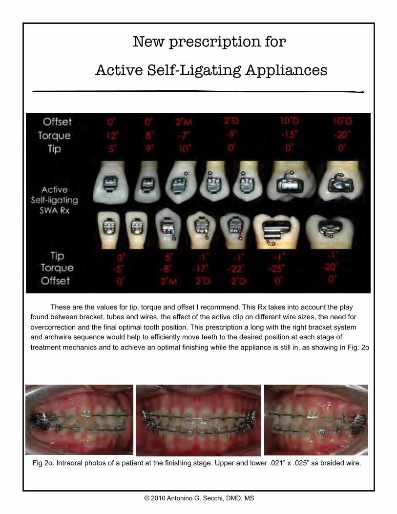
These are the values for tip, torque and offset I recommend. This Rx takes into account the play found between bracket, tubes and wires, the effect of the active clip on different wire sizes, the need for overcorrection and the final optimal tooth position. This prescription a long with the right bracket system and archwire sequence would help to efficiently move teeth to the desired position at each stage of treatment mechanics and to achieve an optimal finishing while the appliance is still in, as showing in Fig. 2o
Fig 2o. Intraoral photos of a patient at the finishing stage. Upper and lower .021” x .025” ss braided wire.
© 2010 Antonino G. Secchi, DMD, MS
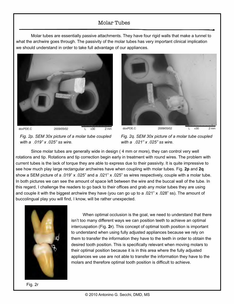
Molar tubes are essentially passive attachments. They have four rigid walls that make a tunnel to what the archwire goes through. The passivity of the molar tubes has very important clinical implication we should understand in order to take full advantage of our appliances.
Fig. 2p. SEM 30x picture of a molar tube coupled with a .019” x .025” ss wire.
Fig. 2q. SEM 30x picture of a molar tube coupled with a .021” x .025” ss wire.
Since molar tubes are generally wide in design ( 4 mm or more), they can control very well rotations and tip. Rotations and tip correction begin early in treatment with round wires. The problem with current tubes is the lack of torque they are able to express due to their passivity. It is quite impressive to see how much play large rectangular archwires have when coupling with molar tubes. Fig. 2p and 2q show a SEM picture of a .019” x .025” and a .021” x .025” ss wires respectively, couple with a molar tube. In both pictures we can see the amount of space left between the wire and the buccal wall of the tube. In this regard, I challenge the readers to go back to their offices and grab any molar tubes they are using and couple it with the biggest archwire they have (you can go up to a .021” x .028” ss). The amount of buccolingual play you will find, I know, will be rather unexpected.
Fig. 2r
When optimal occlusion is the goal, we need to understand that there isn’t too many different ways we can position teeth to achieve an optimal intercuspation (Fig. 2r). This concept of optimal tooth position is important to understand when using fully adjusted appliances because we rely on them to transfer the information they have to the teeth in order to obtain the desired tooth position. This is specifically relevant when moving molars to their optimal position because it is in this area where the fully adjusted appliances we use are not able to transfer the information they have to the molars and therefore optimal tooth position is difficult to achieve.
Molar Tubes
© 2010 Antonino G. Secchi, DMD, MS
There are three reasons that explain the lack of torque control on maxillary and mandibular molars.
1. Molars eruption pattern and occlusal forces.2. Concept of terminal tooth for the second molars.3. Molar tubes are passive attachments.
Molars eruption pattern and occlusal forces
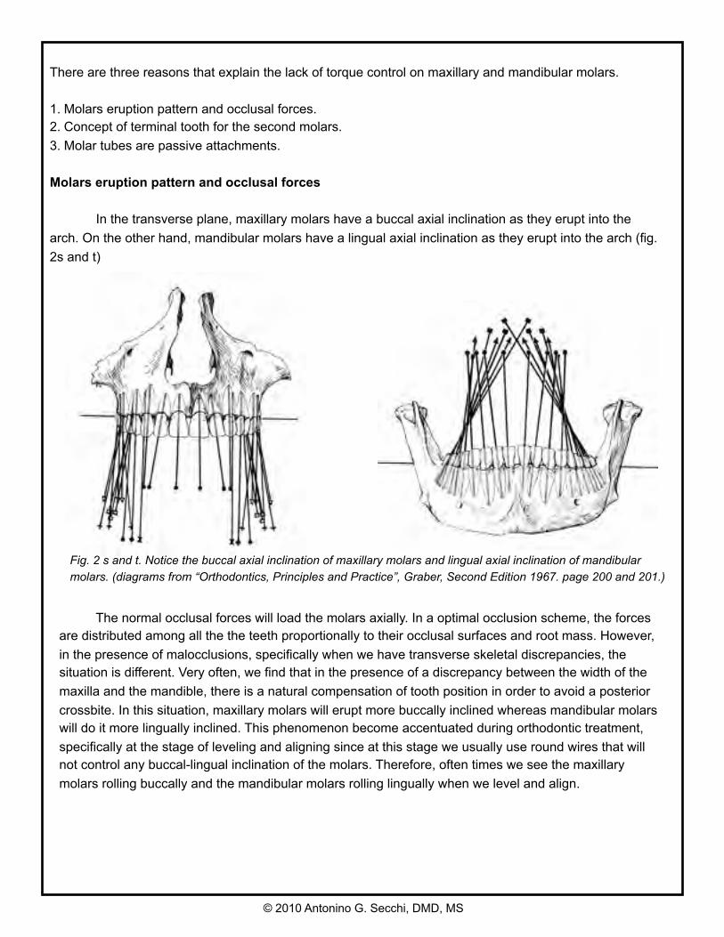
In the transverse plane, maxillary molars have a buccal axial inclination as they erupt into the arch. On the other hand, mandibular molars have a lingual axial inclination as they erupt into the arch (fig. 2s and t)
Fig. 2 s and t. Notice the buccal axial inclination of maxillary molars and lingual axial inclination of mandibular molars. (diagrams from “Orthodontics, Principles and Practice”, Graber, Second Edition 1967. page 200 and 201.)
The normal occlusal forces will load the molars axially. In a optimal occlusion scheme, the forces are distributed among all the the teeth proportionally to their occlusal surfaces and root mass. However, in the presence of malocclusions, specifically when we have transverse skeletal discrepancies, the situation is different. Very often, we find that in the presence of a discrepancy between the width of the maxilla and the mandible, there is a natural compensation of tooth position in order to avoid a posterior crossbite. In this situation, maxillary molars will erupt more buccally inclined whereas mandibular molars will do it more lingually inclined. This phenomenon become accentuated during orthodontic treatment, specifically at the stage of leveling and aligning since at this stage we usually use round wires that will not control any buccal-lingual inclination of the molars. Therefore, often times we see the maxillary molars rolling buccally and the mandibular molars rolling lingually when we level and align.
© 2010 Antonino G. Secchi, DMD, MS
Concept of terminal tooth for the second molars
Usually, the problem correcting the buccolingual inclination of molars is more common for the second molars than for the first one. This happens because the second molar is a terminal tooth in the arch. The fact that the archwire stops at the second molar tube and does not go to another more distal tooth, diminishes substantially the amount of control we have over it. The lack of control occurs for any terminal tooth in the arch. For instance, we have all had the difficult experience of trying to correct a rotated premolar on a partially edentulous patient where the premolar is the terminal tooth. It can be done, but it is a lot easier when the wire goes from the premolar to the molar rather than stop at the premolar.
Molar tubes are passive attachments
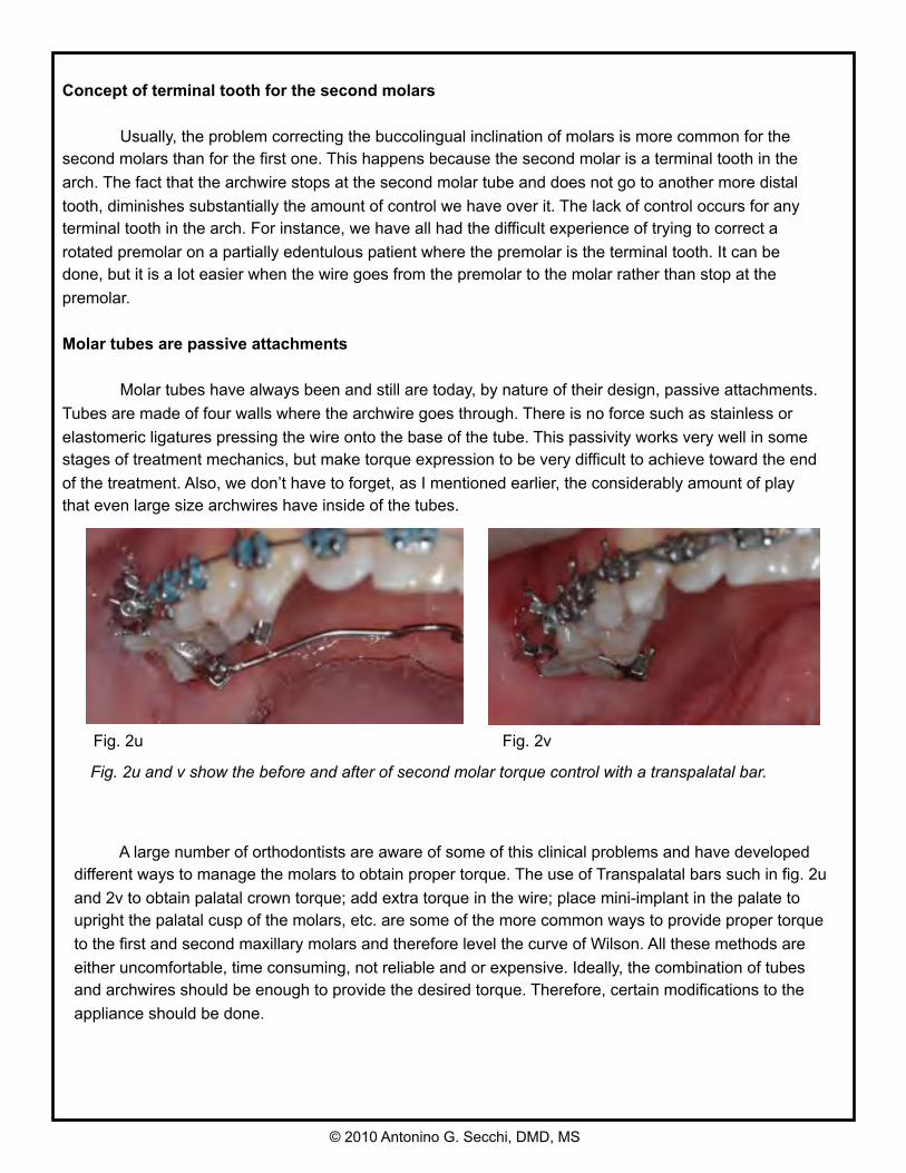
Molar tubes have always been and still are today, by nature of their design, passive attachments. Tubes are made of four walls where the archwire goes through. There is no force such as stainless or elastomeric ligatures pressing the wire onto the base of the tube. This passivity works very well in some stages of treatment mechanics, but make torque expression to be very difficult to achieve toward the end of the treatment. Also, we don’t have to forget, as I mentioned earlier, the considerably amount of play that even large size archwires have inside of the tubes.
A large number of orthodontists are aware of some of this clinical problems and have developed different ways to manage the molars to obtain proper torque. The use of Transpalatal bars such in fig. 2u and 2v to obtain palatal crown torque; add extra torque in the wire; place mini-implant in the palate to upright the palatal cusp of the molars, etc. are some of the more common ways to provide proper torque to the first and second maxillary molars and therefore level the curve of Wilson. All these methods are either uncomfortable, time consuming, not reliable and or expensive. Ideally, the combination of tubes and archwires should be enough to provide the desired torque. Therefore, certain modifications to the appliance should be done.
Fig. 2u and v show the before and after of second molar torque control with a transpalatal bar.
Fig. 2u Fig. 2v
© 2010 Antonino G. Secchi, DMD, MS
Controlling molar inclination “torque”
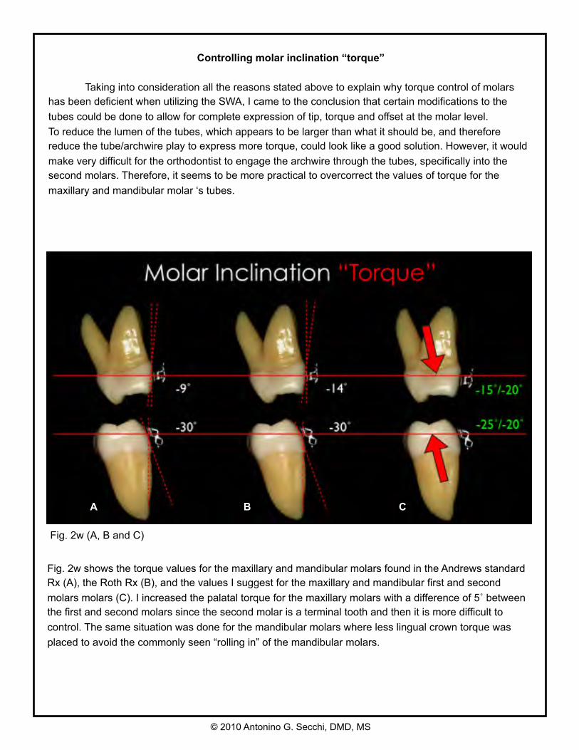
Taking into consideration all the reasons stated above to explain why torque control of molars has been deficient when utilizing the SWA, I came to the conclusion that certain modifications to the tubes could be done to allow for complete expression of tip, torque and offset at the molar level.To reduce the lumen of the tubes, which appears to be larger than what it should be, and therefore reduce the tube/archwire play to express more torque, could look like a good solution. However, it would make very difficult for the orthodontist to engage the archwire through the tubes, specifically into the second molars. Therefore, it seems to be more practical to overcorrect the values of torque for the maxillary and mandibular molar ‘s tubes.
Fig. 2w (A, B and C)
A B C
Fig. 2w shows the torque values for the maxillary and mandibular molars found in the Andrews standard Rx (A), the Roth Rx (B), and the values I suggest for the maxillary and mandibular first and second molars molars (C). I increased the palatal torque for the maxillary molars with a difference of 5˚ between the first and second molars since the second molar is a terminal tooth and then it is more difficult to control. The same situation was done for the mandibular molars where less lingual crown torque was placed to avoid the commonly seen “rolling in” of the mandibular molars.
© 2010 Antonino G. Secchi, DMD, MS
Controlling incisors inclination “torque”
The optimal inclination “torque” of the maxillary and mandibular incisors is a very important area to discuss on. It affects the anterior coupling of the incisors and therefore the anterior guidance. Specifically for the maxillary incisors, to achieve optimal torque is sometimes difficult due to the large amount of bone the roots of these teeth must go through. The inclination of the mandibular incisors is important too, since an orthodontic goal is to position them upright onto the alveolar bone for greater stability and function. The following clinical situations are more demanding with respect of torque control:- some Class II div I extraction cases where maxillary incisors need to be retracted without losing
inclination.- Class II div II, where labial crown inclination of maxillary incisors have to be fully expressed.- Class III camouflage, crowding and Class II mechanics, deep curve of Spee, etc. are specifically
challenging with regard of the upright position of mandibular incisors.
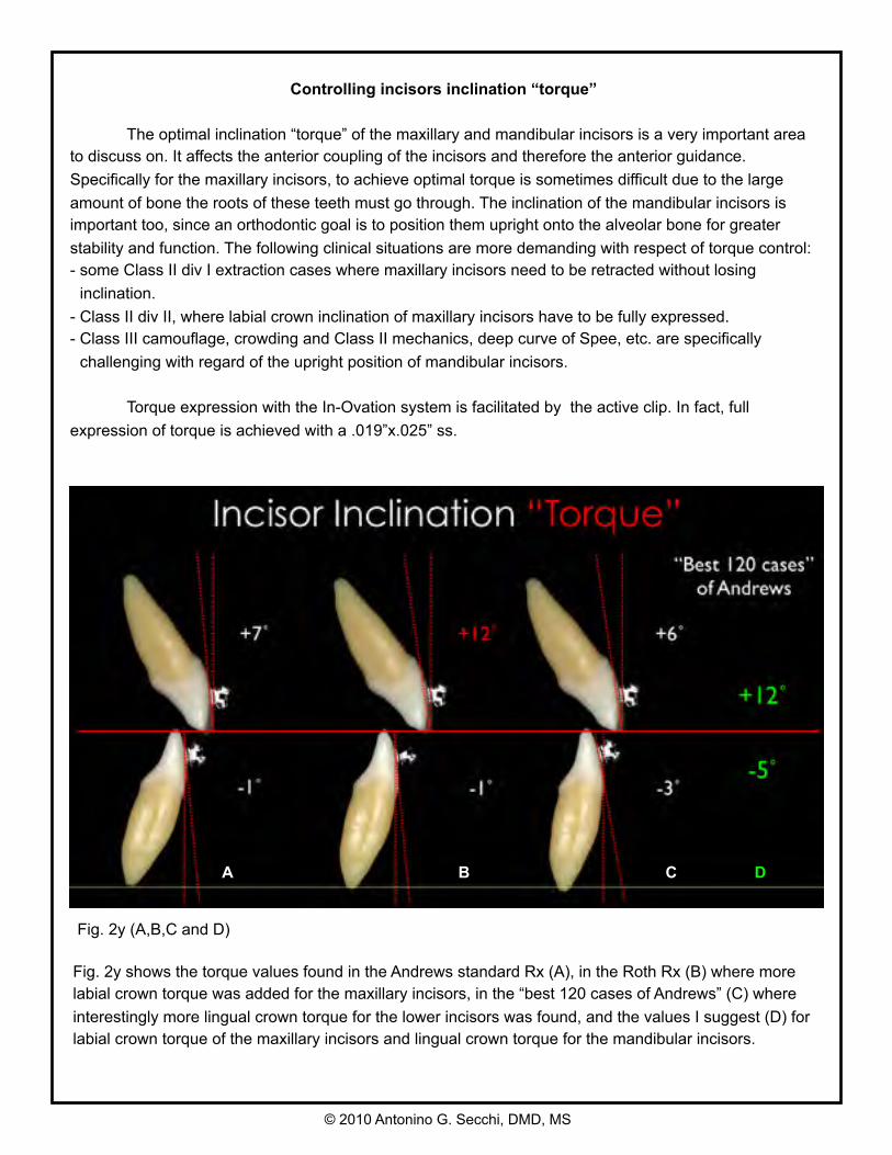
Torque expression with the In-Ovation system is facilitated by the active clip. In fact, full expression of torque is achieved with a .019”x.025” ss.
Fig. 2y (A,B,C and D)
Fig. 2y shows the torque values found in the Andrews standard Rx (A), in the Roth Rx (B) where more labial crown torque was added for the maxillary incisors, in the “best 120 cases of Andrews” (C) where interestingly more lingual crown torque for the lower incisors was found, and the values I suggest (D) for labial crown torque of the maxillary incisors and lingual crown torque for the mandibular incisors.
A B C D
© 2010 Antonino G. Secchi, DMD, MS
T r e a t m e n t M e c h a n i c s
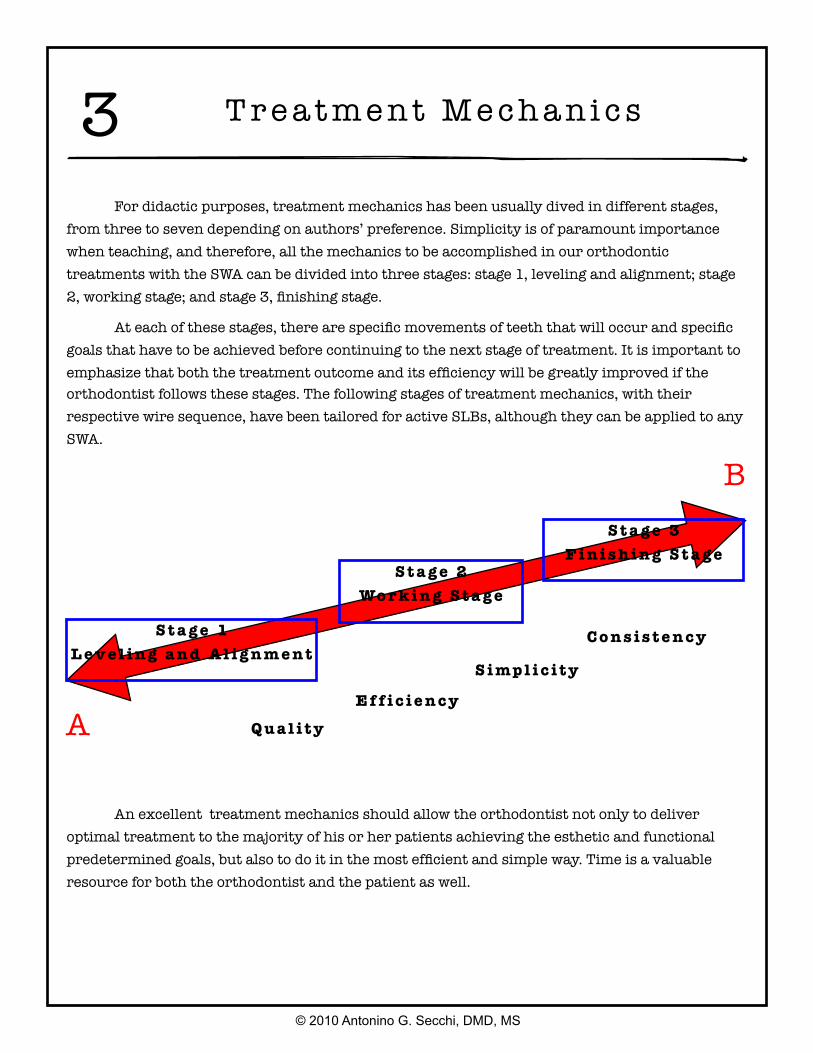
For didactic purposes, treatment mechanics has been usually dived in different stages, from three to seven depending on authors’ preference. Simplicity is of paramount importance when teaching, and therefore, all the mechanics to be accomplished in our orthodontic treatments with the SWA can be divided into three stages: stage 1, leveling and alignment; stage 2, working stage; and stage 3, finishing stage.
At each of these stages, there are specific movements of teeth that will occur and specific goals that have to be achieved before continuing to the next stage of treatment. It is important to emphasize that both the treatment outcome and its efficiency will be greatly improved if the orthodontist follows these stages. The following stages of treatment mechanics, with their respective wire sequence, have been tailored for active SLBs, although they can be applied to any SWA.
© 2010 Antonino G. Secchi, DMD, MS
3
S t a g e 1L e v e l i n g a n d A l i g n m e n t
S t a g e 2Wo r k i n g S t a g e
S t a g e 3F i n i s h i n g S t a g e
A
B
An excellent treatment mechanics should allow the orthodontist not only to deliver optimal treatment to the majority of his or her patients achieving the esthetic and functional predetermined goals, but also to do it in the most efficient and simple way. Time is a valuable resource for both the orthodontist and the patient as well.
E f f i c i e n c y
S i mp l i c i t y
Q u a l i t y
C o n s i s t e n c y
Stage 1 Leveling and Aligning
© 2010 Antonino G. Secchi, DMD, MS
Leveling and aligning is a complex process where all the crowns are moving at the same time and in different directions. As the teeth level and align, reciprocal forces between them develop, which can be of great help to guide the movements to our advantage. Then, when possible, all teeth should be engage from the beginning to obtain maximum efficiency of tooth movement. Usually at this stage, round small-diameter thermal-activated wires such as a 0.014-inch Sentalloy for severe crowing or an 0.018-inch Sentalloy for moderate to minimum crowding are preferred. It is recommended to place crimpable stops to avoid undesirable movement of the wire, causing discomfort to the patient. These round wires can be in place for as long as 8 to 12 weeks before proceeding to the next wire, which usually is a 0.020- × 0.020-inch Bioforce. The Bioforce wire is a low-deflection thermal-activated wire that works very well as a transitional wire from stage 1 to stage 2. The 0.020- × 0.020-inch Bioforce corrects most of the rotations left by the previously used round wires and provides more stiffness to start leveling the curve of Spee and therefore flatten the occlusal plane. It is important to notice that even if you could start treatment with a rectangular or square thermal-activated low-deflection wire, with the assumption of saving time and providing torque from the beginning of treatment, this is absolutely not recommended, since it may cause loss of posterior anchorage. This happens for two main reasons: first, the only teeth with positive labial crown torque are the maxillary central and lateral incisors, and second, the mesial crown tip of the maxillary and mandibular canines is rather large. Therefore, if we start treatment resolving the crowding with a rectangular or square wire, we are providing labial crown torque to the maxillary incisors and mesial crown tip to canines, which will increase our anchorage in the front part of the arch facilitating the loss of anchorage in the posterior part of the arch. This is critical in cases where the treatment plan calls for maximum retraction of the maxillary and or mandibular incisors. Conversely, if we start treatment with a round wire of small diameter, we will not provide torque and the tip effect on the canines will be minimal. This will allow the molar and premolars to level, align, and upright, which will produce a “lasso” effect on the incisors that will upright and sometimes even retract them. The 0.020- × 0.020-inch Bioforce will make the clip of the SLB active and thus start delivering torque; nonetheless, its strength is not sufficient to compromise the anchorage that has already been created with the round wires. Usually, after 8 to 10 weeks with the 0.020- × 0.020-inch Bioforce, the stage 1 of leveling and aligning is finished and in the author ‘s opinion it is the first time to evaluate bracket placement and debond/rebond as necessary. Then, we are ready to start stage 2, the working stage.
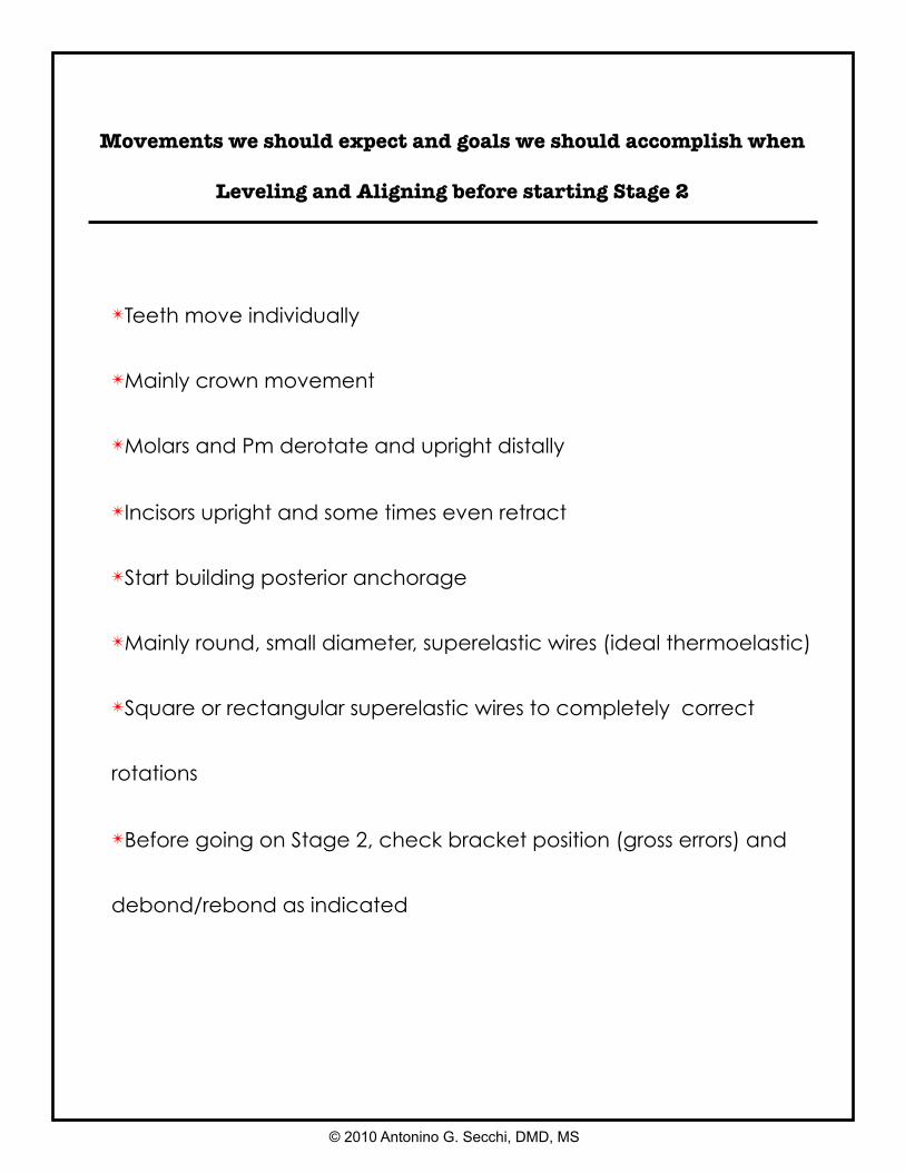
✴Teeth move individually
✴Mainly crown movement
✴Molars and Pm derotate and upright distally
✴Incisors upright and some times even retract
✴Start building posterior anchorage
✴Mainly round, small diameter, superelastic wires (ideal thermoelastic)
✴Square or rectangular superelastic wires to completely correct
rotations
✴Before going on Stage 2, check bracket position (gross errors) and
debond/rebond as indicated
Movements we should expect and goals we should accomplish when
Leveling and Aligning before starting Stage 2
© 2010 Antonino G. Secchi, DMD, MS
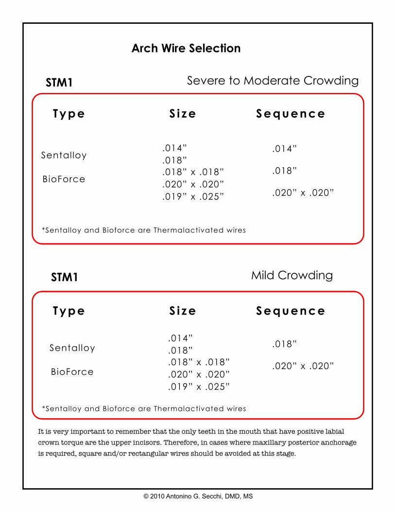
Arch Wire Selection
Type S i ze Sequence
STM1
.014”
.018”
.018” x .018”
.020” x .020”
.019” x .025”
Severe to Moderate Crowding
.014”
.018”
.020” x .020”
Sentalloy
BioForce
*Sentalloy and Bioforce are Thermalactivated wires
.014”
.018”
.018” x .018”
.020” x .020”
.019” x .025”
Mild Crowding
.018”
.020” x .020”
Sentalloy
BioForce
Type S i ze Sequence
STM1
It is very important to remember that the only teeth in the mouth that have positive labial crown torque are the upper incisors. Therefore, in cases where maxillary posterior anchorage is required, square and/or rectangular wires should be avoided at this stage.
© 2010 Antonino G. Secchi, DMD, MS
*Sentalloy and Bioforce are Thermalactivated wires
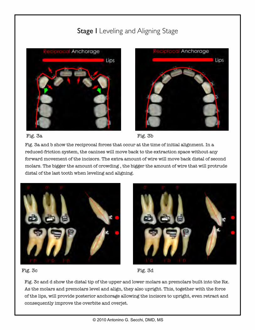
Stage I Leveling and Aligning Stage
Fig. 3a
Fig. 3a and b show the reciprocal forces that occur at the time of initial alignment. In a reduced-friction system, the canines will move back to the extraction space without any forward movement of the incisors. The extra amount of wire will move back distal of second molars. The bigger the amount of crowding , the bigger the amount of wire that will protrude distal of the last tooth when leveling and aligning.
Fig. 3c and d show the distal tip of the upper and lower molars an premolars built into the Rx. As the molars and premolars level and align, they also upright. This, together with the force of the lips, will provide posterior anchorage allowing the incisors to upright, even retract and consequently improve the overbite and overjet.
© 2010 Antonino G. Secchi, DMD, MS
Fig. 3b
Fig. 3c Fig. 3d
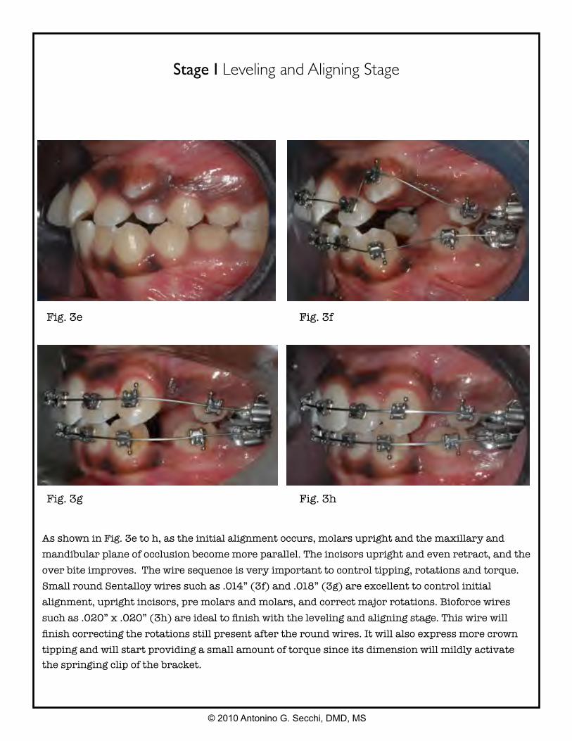
As shown in Fig. 3e to h, as the initial alignment occurs, molars upright and the maxillary and mandibular plane of occlusion become more parallel. The incisors upright and even retract, and the over bite improves. The wire sequence is very important to control tipping, rotations and torque. Small round Sentalloy wires such as .014” (3f) and .018” (3g) are excellent to control initial alignment, upright incisors, pre molars and molars, and correct major rotations. Bioforce wires such as .020” x .020” (3h) are ideal to finish with the leveling and aligning stage. This wire will finish correcting the rotations still present after the round wires. It will also express more crown tipping and will start providing a small amount of torque since its dimension will mildly activate the springing clip of the bracket.
© 2010 Antonino G. Secchi, DMD, MS
Stage I Leveling and Aligning Stage
Fig. 3e Fig. 3f
Fig. 3g Fig. 3h

Fig. 3i and j show how as the initial alignment occurs, molars upright and the maxillary and mandibular plane of occlusion become more parallel helping uprighting and even retracting the incisors and also improving the over bite.
Fig. 3k, l and m show the sequence from a initial .014” Sentalloy (3k) to a .018” Sentalloy (3l) to a .020” x .020” Bioforce wire (3m). No elastics or extraoral force has been used.
© 2010 Antonino G. Secchi, DMD, MS
Stage I Leveling and Aligning Stage
Fig. 3i Fig. 3j
Fig. 3k Fig. 3l
Fig. 3m
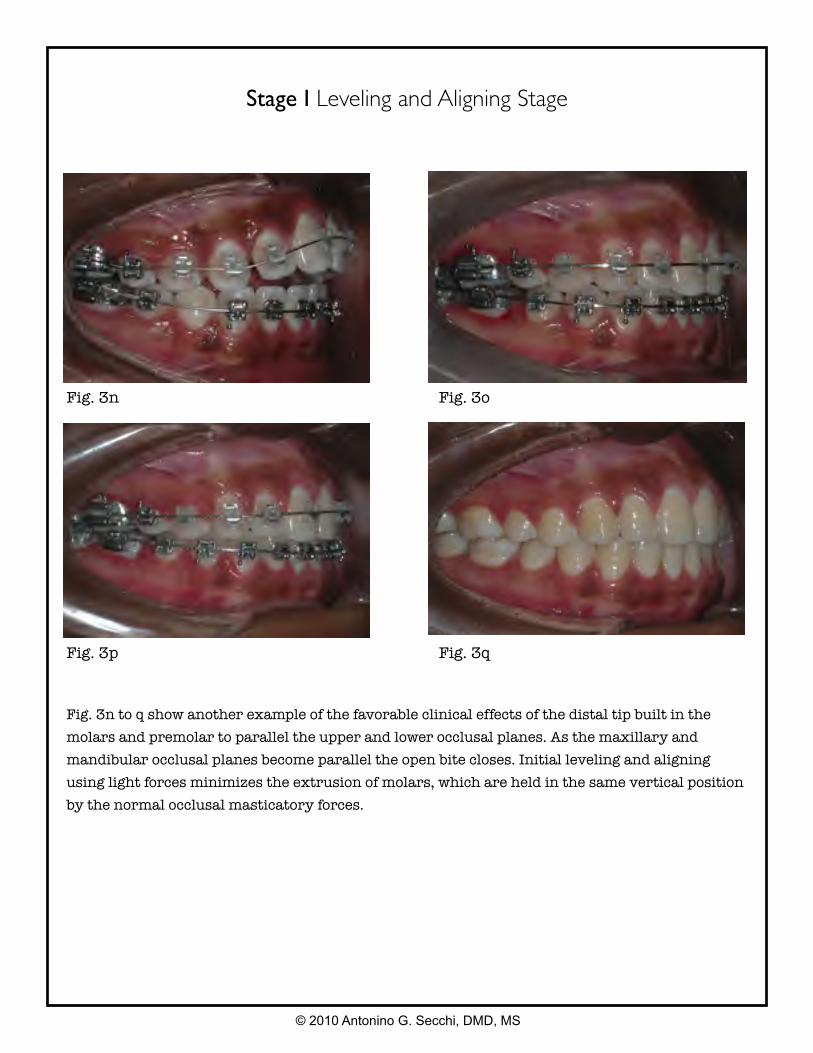
Fig. 3n to q show another example of the favorable clinical effects of the distal tip built in the molars and premolar to parallel the upper and lower occlusal planes. As the maxillary and mandibular occlusal planes become parallel the open bite closes. Initial leveling and aligning using light forces minimizes the extrusion of molars, which are held in the same vertical position by the normal occlusal masticatory forces.
© 2010 Antonino G. Secchi, DMD, MS
Stage I Leveling and Aligning Stage
Fig. 3n Fig. 3o
Fig. 3p Fig. 3q
Stage 2 Working Stage
© 2010 Antonino G. Secchi, DMD, MS
This stage of treatment is the one on which we will spend more time. At this stage, the maxillary and mandibular arches are coordinated, proper overbite and overjet are achieved, Class II or Class III are corrected, maxillary and mandibular midlines are aligned, extraction spaces are closed, and maxillary and mandibular occlusal planes are paralleled. Although most of these corrections happen simultaneously, we will describe them separately for didactic reasons, so key points can be emphasized.
Arch Coordination
The maxillary and mandibular archwires must be coordinated in order to obtain a stable occlusal intercuspation and proper overjet. In an ideal intercuspation of a Class I, one-tooth to two-teeth occlusal scheme, the palatal cusps of the maxillary molars should intercuspate with the fossae and marginal ridges of mandibular molars, the buccal cusp of the mandibular premolars should intercuspate with the marginal ridges of the maxillary premolars, and the mandibular canines and incisors should intercuspate with marginal ridges of the maxillary canines and incisors. If this occlusal scheme occurs, it will then provide an overjet of 2 to 3 mm all around the arch from second molar to second molar. Then, the maxillary archwire must be 2 to 3 mm wider than the mandibular archwire. The archwire coordination is done with the stainless steel wire. Even if they come preformed, the clinician should not rely on it and check them before insertion.
Another important aspect of arch coordination is the effect that it has on the vertical dimension and the sagittal dimension. Arch coordination is a transverse issue. The maxillary teeth should be upright and centered in the alveolar/basal bone and coordinated with the mandibular teeth, which should also be upright and centered in the alveolar/basal bone to obtain a proper intercuspation. Often, this is not the case and we find maxillary molars buccally inclined, also referred as an accentuated curve of Wilson, which can produce contacts between the palatal cusp of maxillary molars and the inclines of the mandibular molars. This decreases the overbite and sometimes produces even an openbite (vertical problem), which in turn can produce a downward and backward movement of the mandible (sagittal problem). This phenomenon is due to the lack of palatal crown torque of the maxillary molars. Depending on the amount of palatal crown torque needed for the maxillary molars to level the curve of Wilson, we suggest three solutions:
1. For minor problems with torque, we can wait until the finishing stage where a larger size wire (0.021- × 0.025-inch stainless steel) can be used to fill the slot and deliver more torque to the molars.
2. For moderate problems with torque, we can add palatal crown torque to the working wire.
© 2010 Antonino G. Secchi, DMD, MS
3. For severe problems with torque, the use of a transpalatal bar (TPB) is suggested. TPB can be used to easily place and deliver palatal crown torque to maxillary molars
Overbite and Overjet Correction
An optimal overbite/overjet relationship does not have to be a certain predetermined number of millimeters. More important is the functional relationship they have. This means that the overbite/overjet should be compatible with a mutually protected occlusal scheme and thus allows for a proper anterior guidance in protrusion and lateral excursive movements. Although, as we said, the number of millimeters is less important than the function, we find that an optimal overbite is usually around 4 mm and an optimal overjet is 2 to 3 mm.
When diagnosing and treatment planning overbite/overjet problems, it is important to take the following key points into consideration: arch space management, position of the mandible in centric relation, and relationship of the upper/lower incisors with the lips. Arch space management is important to understand since the SWA tend to flatten the curve of Spee, which requires space in the arch. If not enough space is available or created, the incisors will procline, increasing the arch perimeter. This incisor proclination will also decrease the overbite and may help, if it only occurs in the lower arch, to decrease the overjet.
Flattening the maxillary and mandibular occlusal planes proclining the incisors can be of help in deep bite cases. When the incisors are not allowed to procline, space in the arch must be created. This is specifically important to avoid periodontal problems in cases with thin bone surrounding the incisors area. Advanced diagnostic imaging tools such as the CBCT could be of great help to precisely identify the condition of the bone in this area. Up to 4 to 6 mm can be created with interproximal reduction of teeth, usually done on the incisors and, less often, the canines and premolars. If more than 6 mm of space is required, extraction of premolars could be indicated.
Another important factor to consider when evaluating overbite/overjet problems is the position of the mandible. Often, differences between a maximum intercuspation (MIC) and centric relation (CR) can produce significant differences in the overbite/overjet relationship. In many cases we find that as the mandible rotates close in CR, a primary contact, usually at the second molar keeps the bite open in the anterior, decreasing the overbite and preventing the mandible to achieve a more stable occlusal scheme.
At last, but by no means the least important, is the sagittal and vertical relationship of the maxillary and mandibular incisors with the lips. In an openbite case, should we intrude the molars or extrude the incisors? In a deep bite case, should we intrude the maxillary incisors, the lower, both? These basic but very important questions can be answered through an understanding of the optimal relationship of the incisors with the lips. According to contemporary aesthetic trends and taking into account the aging process, for adolescents and young adults, maxillary incisors should have, at rest, an exposure of about 4 mm beyond the most inferior point of the upper lip known as upper stomion. As explained earlier, an optimal functional overbite should be about 4 mm. Now, if we put together the last two concepts, the incisal edge of the lower incisors should be at the same level with the most inferior point of the
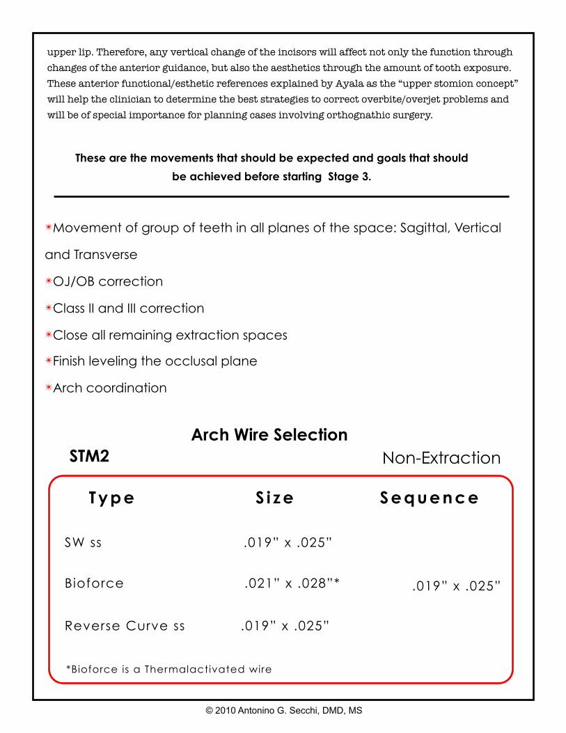
✴Movement of group of teeth in all planes of the space: Sagittal, Vertical
and Transverse
✴OJ/OB correction
✴Class II and III correction
✴Close all remaining extraction spaces
✴Finish leveling the occlusal plane
✴Arch coordination
These are the movements that should be expected and goals that should
be achieved before starting Stage 3.
STM2
SW ss .019” x .025”
Reverse Curve ss .019” x .025”
Non-Extraction
.019” x .025”Bioforce .021” x .028”*
Type S i ze Sequence
Arch Wire Selection
© 2010 Antonino G. Secchi, DMD, MS
*Bioforce is a Thermalactivated wire
upper lip. Therefore, any vertical change of the incisors will affect not only the function through changes of the anterior guidance, but also the aesthetics through the amount of tooth exposure. These anterior functional/esthetic references explained by Ayala as the “upper stomion concept” will help the clinician to determine the best strategies to correct overbite/overjet problems and will be of special importance for planning cases involving orthognathic surgery.
© 2010 Antonino G. Secchi, DMD, MS
Usually after leveling and aligning, the extraction spaces left are smaller than at the beginning of treatment since some of the space has been taken to unravel the initial crowding and to upright the maxillary and mandibular incisors, as described earlier on this manual. Also, the maxillary and mandibular occlusal planes should be flat or almost flat, and the six anterior teeth should be consolidated into one unit. Then, to efficiently close the remaining spaces, achieving the desired functional and aesthetic goals, we need to determine the anchorage requirement. This will allow us to know which teeth should be moved more mesially or distally and therefore to choose the appropriate mechanics.
We believe that one of the easiest ways to determine the anchorage requirement is to perform a visual treatment objective (VTO). The VTO is a cephalometric exercise where we modify the patient’s cephalometric tracing to achieve the desired “end of treatment” result and then, by superimposing both tracings, we can visualize the movements that need to occur to obtain that result. The VTO is not a formula or equation that will determine or impose a specific type of treatment, but rather an exercise where we take into account our experience gathered from other similar cases, an estimation of the growth the patient will have during treatment, the patient’s biotype and soft tissue characteristic, and so on to more accurately treatment plan our cases and have a visual representation of it. Thus, after the VTO has been performed, the anchorage requirement can be minimum, medium, or maximum.
Before describing each one of these anchorage situations, it is important to indicate the wires and auxiliaries used at this stage. In our mechanics, we use either a double keyhole loop (DKH) or a straight wire with hooks and Sentalloy coils (Sentalloy is a trademarked brand of GAC International, Bohemia, NY). Both of these types of wires are stainless steel and can be either 0.019- × 0.025-inch or 0.021- × 0.025-inch, depending on the anchorage situation. The Sentalloy coils can be light (100 g), medium (150 g), or heavy (200 g). Also, when the anchorage situation calls for it, we use TPBs and temporary anchorage devices (TADs).
Closing Extraction Spaces
© 2010 Antonino G. Secchi, DMD, MS
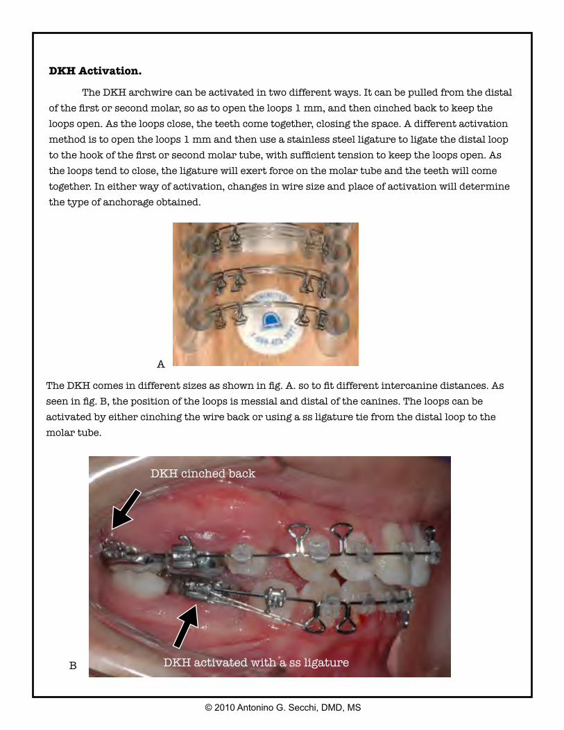
DKH Activation.
The DKH archwire can be activated in two different ways. It can be pulled from the distal of the first or second molar, so as to open the loops 1 mm, and then cinched back to keep the loops open. As the loops close, the teeth come together, closing the space. A different activation method is to open the loops 1 mm and then use a stainless steel ligature to ligate the distal loop to the hook of the first or second molar tube, with sufficient tension to keep the loops open. As the loops tend to close, the ligature will exert force on the molar tube and the teeth will come together. In either way of activation, changes in wire size and place of activation will determine the type of anchorage obtained.
DKH cinched back
DKH activated with a ss ligature
The DKH comes in different sizes as shown in fig. A. so to fit different intercanine distances. As seen in fig. B, the position of the loops is messial and distal of the canines. The loops can be activated by either cinching the wire back or using a ss ligature tie from the distal loop to the molar tube.
A
B
© 2010 Antonino G. Secchi, DMD, MS
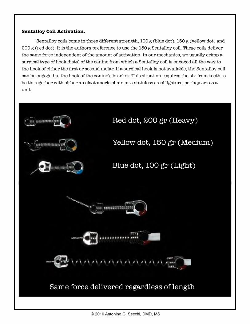
Sentalloy Coil Activation.
Sentalloy coils come in three different strength, 100 g (blue dot), 150 g (yellow dot) and 200 g (red dot). It is the authors preference to use the 150 g Sentalloy coil. These coils deliver the same force independent of the amount of activation. In our mechanics, we usually crimp a surgical type of hook distal of the canine from which a Sentalloy coil is engaged all the way to the hook of either the first or second molar. If a surgical hook is not available, the Sentalloy coil can be engaged to the hook of the canine’s bracket. This situation requires the six front teeth to be tie together with either an elastomeric chain or a stainless steel ligature, so they act as a unit.
Red dot, 200 gr (Heavy)
Yellow dot, 150 gr (Medium)
Blue dot, 100 gr (Light)
Same force delivered regardless of length
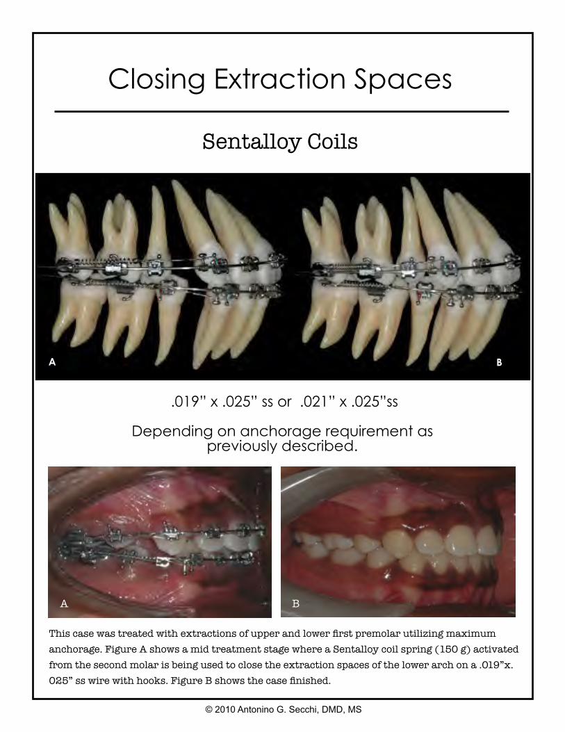
.019” x .025” ss or .021” x .025”ss
Depending on anchorage requirement as previously described.
This case was treated with extractions of upper and lower first premolar utilizing maximum anchorage. Figure A shows a mid treatment stage where a Sentalloy coil spring (150 g) activated from the second molar is being used to close the extraction spaces of the lower arch on a .019”x.025” ss wire with hooks. Figure B shows the case finished.
A B
A B
© 2010 Antonino G. Secchi, DMD, MS
Closing Extraction Spaces
Sentalloy Coils
Closing Extraction Spaces
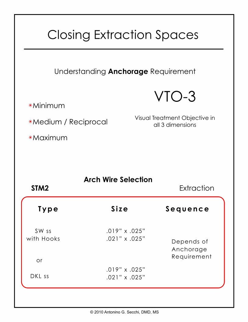
Understanding Anchorage Requirement
✴Minimum
✴Medium / Reciprocal
✴Maximum
VTO-3Visual Treatment Objective in
all 3 dimensions
STM2
SW ss with Hooks
.019” x .025”
.021” x .025”
DKL ss
Extraction
Depends of Anchorage Requirement
.019” x .025”
.021” x .025”
or
Type S i ze Sequence
Arch Wire Selection
© 2010 Antonino G. Secchi, DMD, MS
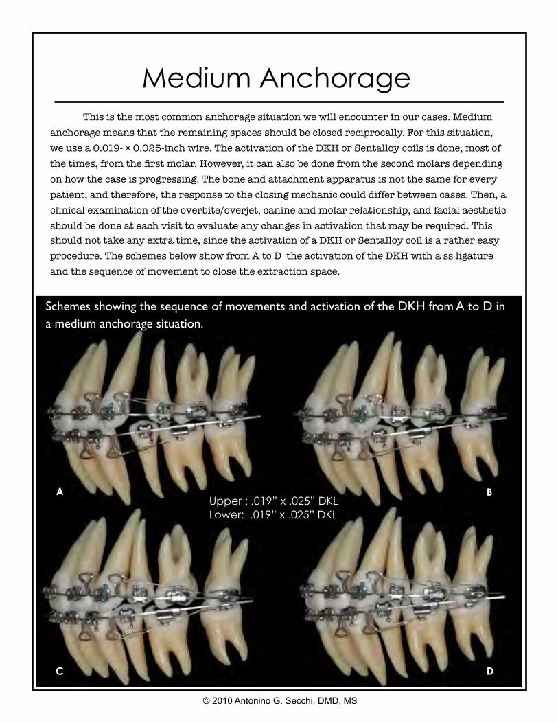
Medium Anchorage
Schemes showing the sequence of movements and activation of the DKH from A to D in a medium anchorage situation.
Upper : .019” x .025” DKLLower: .019” x .025” DKL
A B
C D
© 2010 Antonino G. Secchi, DMD, MS
This is the most common anchorage situation we will encounter in our cases. Medium anchorage means that the remaining spaces should be closed reciprocally. For this situation, we use a 0.019- × 0.025-inch wire. The activation of the DKH or Sentalloy coils is done, most of the times, from the first molar. However, it can also be done from the second molars depending on how the case is progressing. The bone and attachment apparatus is not the same for every patient, and therefore, the response to the closing mechanic could differ between cases. Then, a clinical examination of the overbite/overjet, canine and molar relationship, and facial aesthetic should be done at each visit to evaluate any changes in activation that may be required. This should not take any extra time, since the activation of a DKH or Sentalloy coil is a rather easy procedure. The schemes below show from A to D the activation of the DKH with a ss ligature and the sequence of movement to close the extraction space.
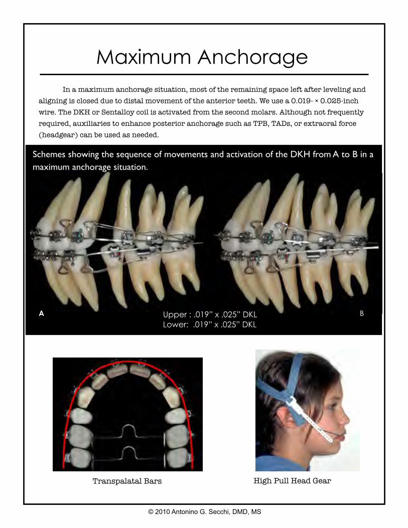
High Pull Head Gear
Upper : .019” x .025” DKLLower: .019” x .025” DKL
A B
© 2010 Antonino G. Secchi, DMD, MS
Maximum Anchorage In a maximum anchorage situation, most of the remaining space left after leveling and aligning is closed due to distal movement of the anterior teeth. We use a 0.019- × 0.025-inch wire. The DKH or Sentalloy coil is activated from the second molars. Although not frequently required, auxiliaries to enhance posterior anchorage such as TPB, TADs, or extraoral force (headgear) can be used as needed.
Transpalatal Bars
Schemes showing the sequence of movements and activation of the DKH from A to B in a maximum anchorage situation.
Upper : .021” x .025” DKLLower: .021” x .025” DKL
A
B
C D
© 2010 Antonino G. Secchi, DMD, MS
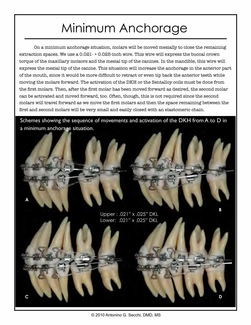
Minimum Anchorage On a minimum anchorage situation, molars will be moved mesially to close the remaining extraction spaces. We use a 0.021- × 0.025-inch wire. This wire will express the buccal crown torque of the maxillary incisors and the mesial tip of the canines. In the mandible, this wire will express the mesial tip of the canine. This situation will increase the anchorage in the anterior part of the mouth, since it would be more difficult to retract or even tip back the anterior teeth while moving the molars forward. The activation of the DKH or the Sentalloy coils must be done from the first molars. Then, after the first molar has been moved forward as desired, the second molar can be activated and moved forward, too. Often, though, this is not required since the second molars will travel forward as we move the first molars and then the space remaining between the first and second molars will be very small and easily closed with an elastomeric chain.
Schemes showing the sequence of movements and activation of the DKH from A to D in a minimum anchorage situation.
A B
C D
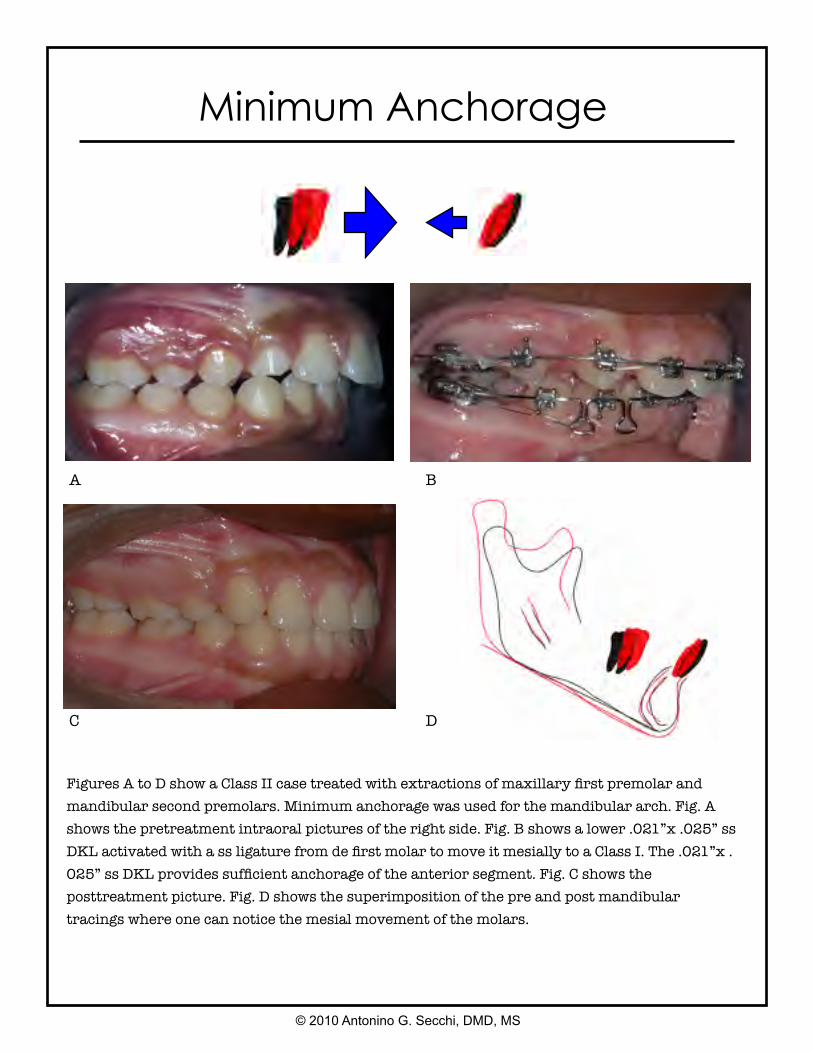
Figures A to D show a Class II case treated with extractions of maxillary first premolar and mandibular second premolars. Minimum anchorage was used for the mandibular arch. Fig. A shows the pretreatment intraoral pictures of the right side. Fig. B shows a lower .021”x .025” ss DKL activated with a ss ligature from de first molar to move it mesially to a Class I. The .021”x .025” ss DKL provides sufficient anchorage of the anterior segment. Fig. C shows the posttreatment picture. Fig. D shows the superimposition of the pre and post mandibular tracings where one can notice the mesial movement of the molars.
© 2010 Antonino G. Secchi, DMD, MS
Minimum Anchorage
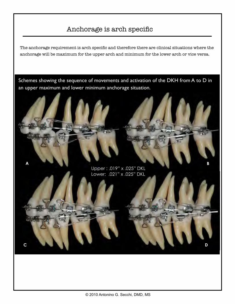
Upper : .019” x .025” DKLLower: .021” x .025” DKL
A B
C D
© 2010 Antonino G. Secchi, DMD, MS
Schemes showing the sequence of movements and activation of the DKH from A to D in an upper maximum and lower minimum anchorage situation.
The anchorage requirement is arch specific and therefore there are clinical situations where the anchorage will be maximum for the upper arch and minimum for the lower arch or vice versa.
Anchorage is arch specific

Intermaxillary Elastics
© 2010 Antonino G. Secchi, DMD, MS
Discretion is a good word to describe the use of intermaxillary elastics. We use them and like them, but it is important to understand how they are used, in this mechanics, to avoid problems.
We do not use intermaxillary elastics in the following situations:
• Round wires• Initial leveling and aligning, low-deflection wires• To a terminal tooth, last tooth in the arch• In the anterior part of the mouth to close openbites• In the posterior part of the mouth to correct crossbites• For a long, extended period of time
We use intermaxillary elastics in the following situations:
• At the working and finishing stages• On square or rectangular stainless steel wires• On the buccal side of the mouth, short Class II or III and/or triangular verticals
The three types of intermaxillary elastics we commonly use are 3/16-inch 4 oz, 6 oz, and 8 oz elastics. Short means, in a Class II, for instance, from the maxillary canine to the mandibular second premolar in a nonextraction case and to the first mandibular molar in an extraction case.
Short double Class II 3/16” 6 oz. Maxillary and mandibular
.019” x .025” ss wires.
Short Class III 3/16” 6 oz. Maxillary .021” x .025” ss and
mandibular .019” x .025” ss wires.
Stage 3 Finishing Stage
© 2010 Antonino G. Secchi, DMD, MS
At this stage, to place each tooth on its ideal position and flatten the occlusal plane, full bracket expression is desired and, thus, a larger wire such as a 0.021- × 0.025-inch stainless steel or a 0.022- × 0.028-inch stainless steel may be required. In our experience using the In-Ovation bracket system, which is an active SLB with the clip pushing and sitting the wire onto the slot, often optimal bracket expression is achieved after a 0.019- × 0.025-inch stainless steel has been in place for few months. This is especially true in nonextraction cases with an average curve of Spee. However, in some cases the size and stiffness of a 0.021- × 0.025-inch stainless steel or 0.022- × 0.028-inch stainless steel are indicated, such as in cases with a deep curve of Spee, extraction cases that have required an important amount of tooth movement, and cases that required significant labial crown torque of maxillary incisors such as Class III camouflage cases and Class II, Division 2 cases.
Once the maxillary and mandibular occlusal planes are parallel and all the bracket slots are aligned, bracket position should be carefully checked for minor correction of tooth position and therefore the second time of debond/redond should be done. It is also suggested, at this point in treatment, to mount the models in an articulator to better visualize the intercuspation of the posterior teeth, which is very difficult to do it clinically. The last wire we use is a stainless steel multibraided 0.021- × 0.025-inch archwire. Although this wire is large enough to fill the slot of the bracket and then maintain the tip, torque, and offset of each tooth, its resilience permits both minor bracket repositioning and “end of treatment” optimal intercuspation.
It is important to notice that at this point in treatment, all the appliance interferences should be removed using a finishing carbide burr on a high-speed handpiece. With a thin articular paper, all contacts must be checked. Only tooth-tooth contacts should be allowed. All brackets, tubes, or bands contacts must be removed to allow proper settling. Vertical triangular 3/16-inch elastics, either 6 oz or 8 oz, are used to achieve proper intercuspation. These vertical elastics should not be used, with the braided wire, for more than 6 weeks to avoid rolling premolars and molars lingually, which cannot be detected from the buccal but rather from the lingual, where premolars and/or molars will not be contacting. Finally, before removing the appliance, a complete assessment of the occlusal “end of treatment” goals should be performed. We strive to finish our cases with a static occlusal scheme compatible with the six keys of optimal occlusion as described by Larry Andrews and a dynamic mutually protected occlusal scheme in centric relation as described by Ronald Roth.
Stage 3 Finishing Stage
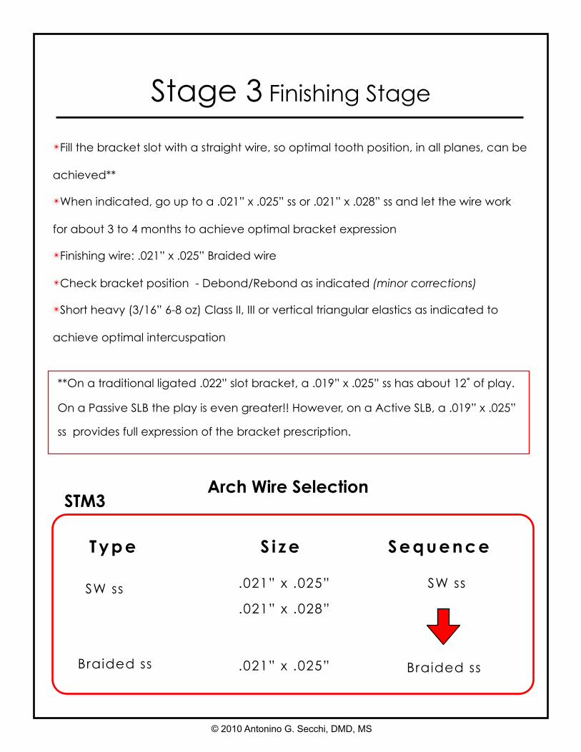
✴Fill the bracket slot with a straight wire, so optimal tooth position, in all planes, can be
achieved**
✴When indicated, go up to a .021” x .025” ss or .021” x .028” ss and let the wire work
for about 3 to 4 months to achieve optimal bracket expression
✴Finishing wire: .021” x .025” Braided wire
✴Check bracket position - Debond/Rebond as indicated (minor corrections)
✴Short heavy (3/16” 6-8 oz) Class II, III or vertical triangular elastics as indicated to
achieve optimal intercuspation
**On a traditional ligated .022” slot bracket, a .019” x .025” ss has about 12˚ of play.
On a Passive SLB the play is even greater!! However, on a Active SLB, a .019” x .025”
ss provides full expression of the bracket prescription.
© 2010 Antonino G. Secchi, DMD, MS
STM3
SW ss .021” x .025”
Braided ss .021” x .025”
Type S i ze Sequence
.021” x .028”
SW ss
Braided ss
Arch Wire Selection
Stage 3 Finishing Stage
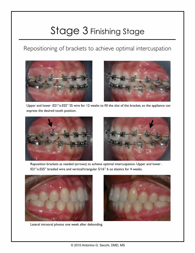
Upper and lower .021”x.025” SS wire for 12 weeks to fill the slot of the bracket, so the appliance can
express the desired tooth position.
Reposition brackets as needed (arrows) to achieve optimal intercuspation. Upper and lower .
021”x.025” braided wire and vertical/triangular 5/16” 6 oz elastics for 4 weeks.
Lateral intraoral photos one week after debonding.
Repositioning of brackets to achieve optimal intercuspation
© 2010 Antonino G. Secchi, DMD, MS

Upper and lower .021”x.025” SS wire for 12 weeks to fill the slot of the bracket, so the appliance can
express the desired tooth position.
Maxillary right and left premolar brackets were rebonded more gingivally. Upper and lower .
021”x.025” braided wire and vertical/triangular 5/16” 6 oz elastics right side and vertical/triangular
Lateral intraoral photos two week after debonding.
Intermaxillary vertical elastics to achieve optimal intercuspation
© 2010 Antonino G. Secchi, DMD, MS
Stage 3 Finishing Stage
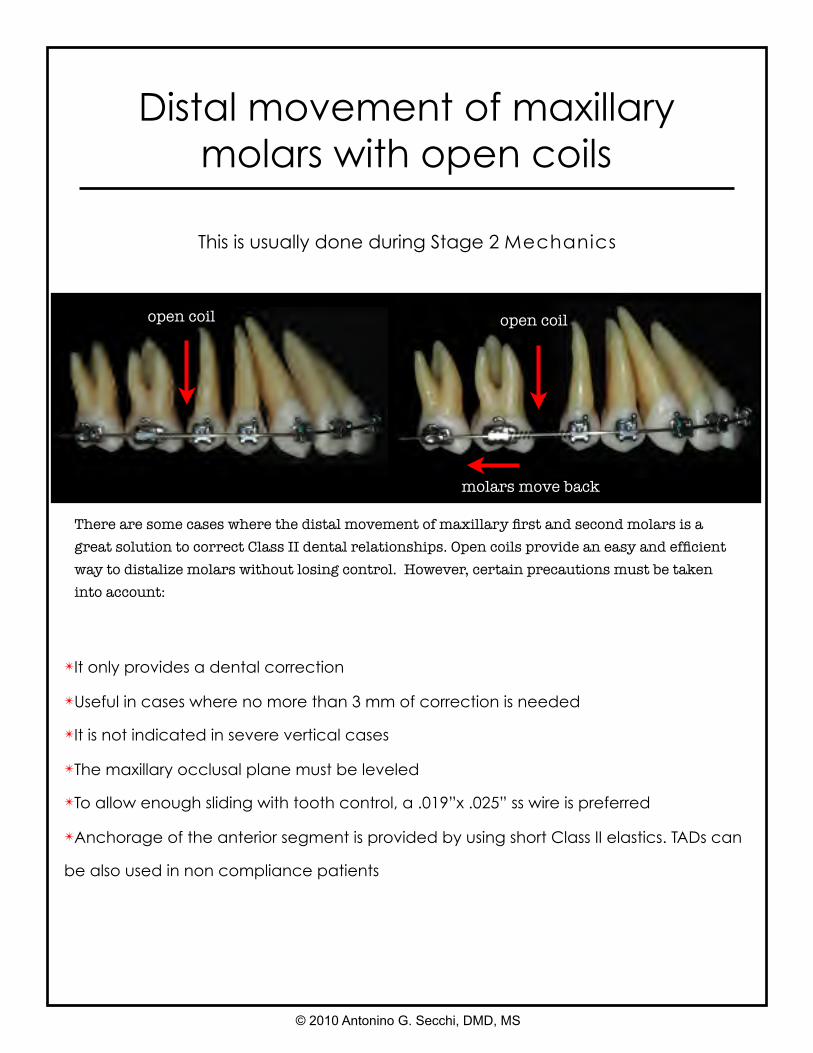
Distal movement of maxillary molars with open coils
✴It only provides a dental correction
✴Useful in cases where no more than 3 mm of correction is needed
✴It is not indicated in severe vertical cases
✴The maxillary occlusal plane must be leveled
✴To allow enough sliding with tooth control, a .019”x .025” ss wire is preferred
✴Anchorage of the anterior segment is provided by using short Class II elastics. TADs can
be also used in non compliance patients
This is usually done during Stage 2 Mechanics
There are some cases where the distal movement of maxillary first and second molars is a great solution to correct Class II dental relationships. Open coils provide an easy and efficient way to distalize molars without losing control. However, certain precautions must be taken into account:
© 2010 Antonino G. Secchi, DMD, MS
open coil open coil
molars move back
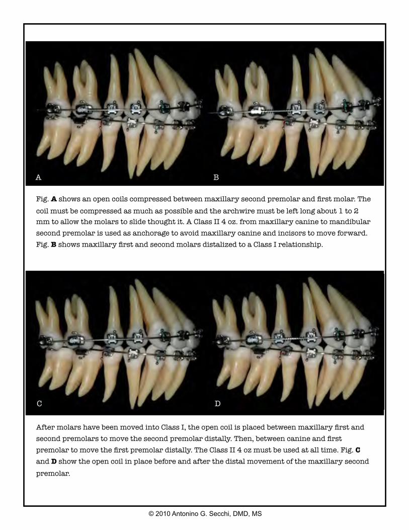
After molars have been moved into Class I, the open coil is placed between maxillary first and second premolars to move the second premolar distally. Then, between canine and first premolar to move the first premolar distally. The Class II 4 oz must be used at all time. Fig. C and D show the open coil in place before and after the distal movement of the maxillary second premolar.
Fig. A shows an open coils compressed between maxillary second premolar and first molar. The coil must be compressed as much as possible and the archwire must be left long about 1 to 2 mm to allow the molars to slide thought it. A Class II 4 oz. from maxillary canine to mandibular second premolar is used as anchorage to avoid maxillary canine and incisors to move forward. Fig. B shows maxillary first and second molars distalized to a Class I relationship.
© 2010 Antonino G. Secchi, DMD, MS
A B
C D
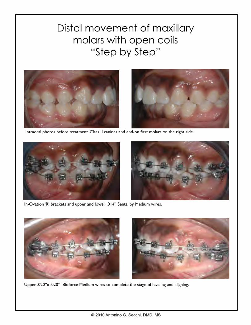
Distal movement of maxillary molars with open coils
“Step by Step”
Intraoral photos before treatment. Class II canines and end-on first molars on the right side.
In-Ovation ‘R’ brackets and upper and lower .014” Sentalloy Medium wires.
Upper .020”x .020” Bioforce Medium wires to complete the stage of leveling and aligning.
© 2010 Antonino G. Secchi, DMD, MS
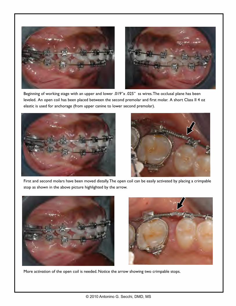
Beginning of working stage with an upper and lower .019”x .025” ss wires. The occlusal plane has been
leveled. An open coil has been placed between the second premolar and first molar. A short Class II 4 oz
elastic is used for anchorage (from upper canine to lower second premolar).
First and second molars have been moved distally. The open coil can be easily activated by placing a crimpable
stop as shown in the above picture highlighted by the arrow.
More activation of the open coil is needed. Notice the arrow showing two crimpable stops.
© 2010 Antonino G. Secchi, DMD, MS
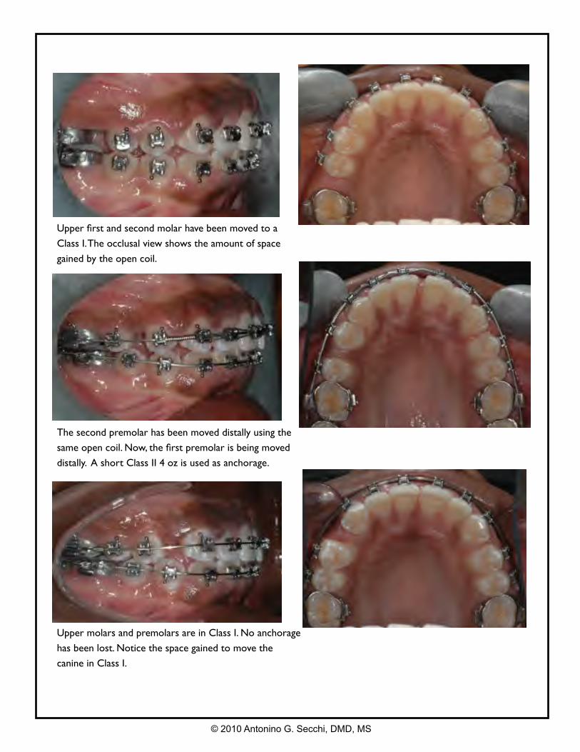
Upper first and second molar have been moved to a
Class I. The occlusal view shows the amount of space
gained by the open coil.
The second premolar has been moved distally using the
same open coil. Now, the first premolar is being moved
distally. A short Class II 4 oz is used as anchorage.
Upper molars and premolars are in Class I. No anchorage
has been lost. Notice the space gained to move the
canine in Class I.
© 2010 Antonino G. Secchi, DMD, MS
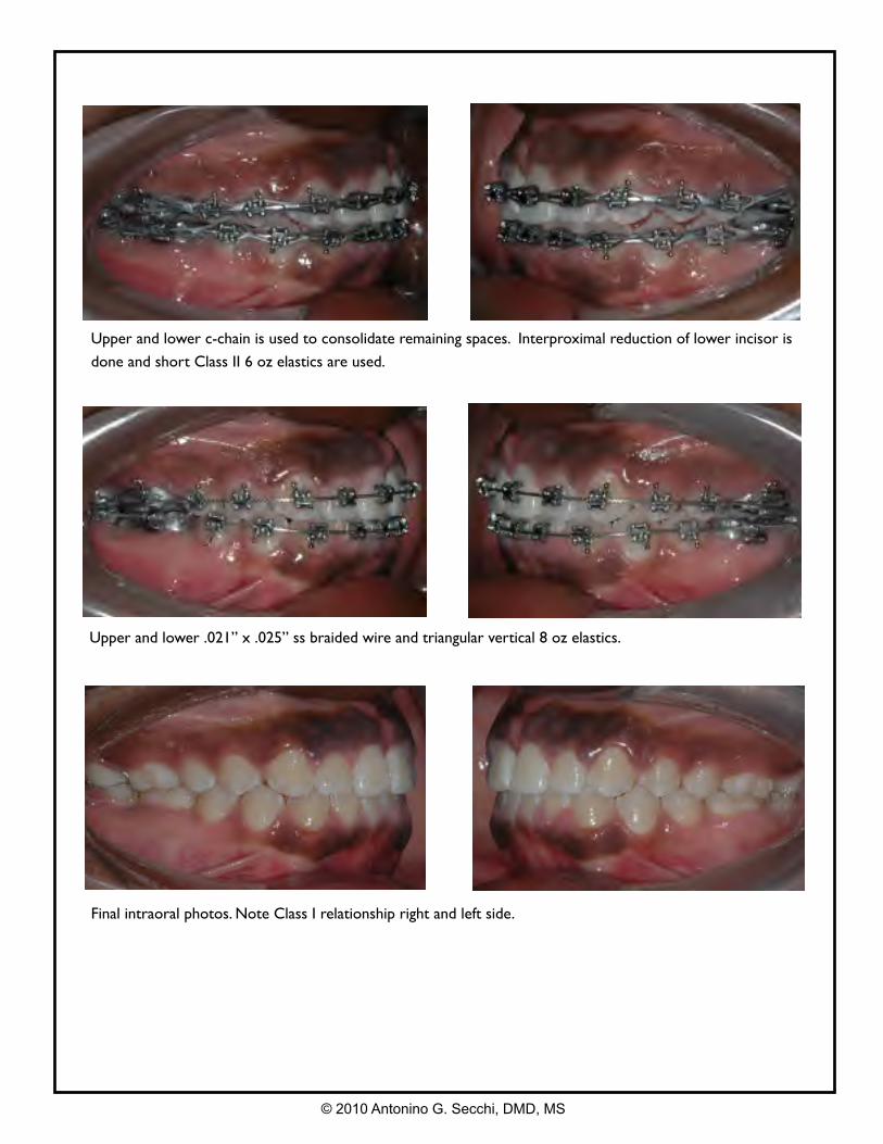
Upper and lower c-chain is used to consolidate remaining spaces. Interproximal reduction of lower incisor is
done and short Class II 6 oz elastics are used.
Upper and lower .021” x .025” ss braided wire and triangular vertical 8 oz elastics.
Final intraoral photos. Note Class I relationship right and left side.
© 2010 Antonino G. Secchi, DMD, MS
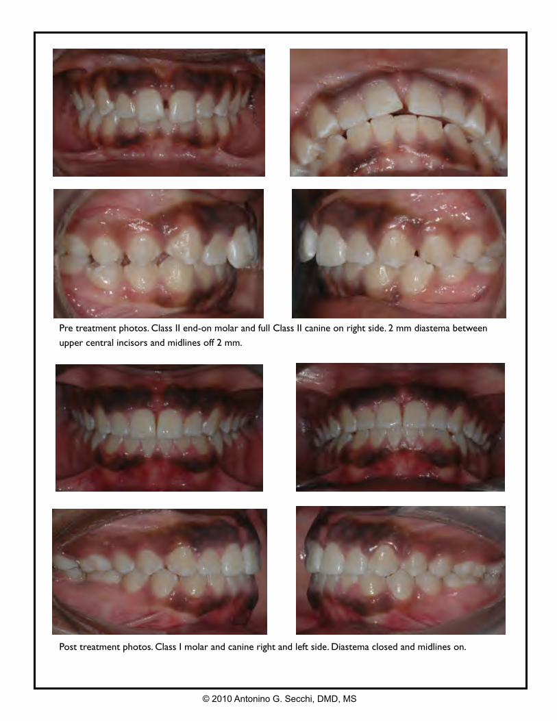
Pre treatment photos. Class II end-on molar and full Class II canine on right side. 2 mm diastema between
upper central incisors and midlines off 2 mm.
Post treatment photos. Class I molar and canine right and left side. Diastema closed and midlines on.
© 2010 Antonino G. Secchi, DMD, MS
Clinical Case
Case # 1: Class I crowding, extractions UL 4’, medium/minimum anchorage.
Case # 2: Class I bimaxillary protrusion, extractions UL 4’, medium anchorage.
Case # 3: Class II end on with upper right canine block out, extractions U4’/L5’,
medium/minimum anchorage.
Case # 4: Class II end on, crowding and protrusion, extractions UL 4’, medium
anchorage.
Case # 5: Class II end on with deep overbite. Non-extraction.
Case # 6: Class II end on with deep overbite. Non-extraction.
Case # 7: Class I with an open bite and posterior crossbite. Non-extraction.
Case # 8: Class II skeletal and dental with a narrow maxilla. Non-extraction.
Case # 9: Class I deep overbite and crowding. Non-extraction.
Case # 10: Class II right side with a deep overbite and increased curve of Spee.
Midlines off. Non-extraction, molar distalization.
© 2010 Antonino G. Secchi, DMD, MS
4 The objective of the following display of clinical cases is to show step by step the correction of different types of commonly found orthodontic problems in the adult dentition. Emphasis is placed on the concepts of mechanics previously discussed in this manual such as stages of treatment, wire sequence, etc. Specific mechanics for Class III malocclusions, combined orthodontic/surgery treatment, TADs, etc. will be discussed separately.
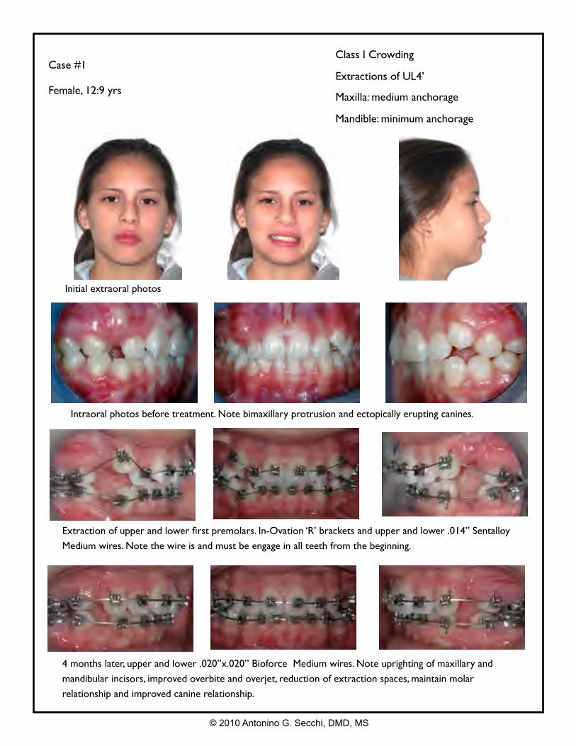
Case #1
Female, 12:9 yrs
Class I Crowding
Extractions of UL4’
Maxilla: medium anchorage
Mandible: minimum anchorage
Intraoral photos before treatment. Note bimaxillary protrusion and ectopically erupting canines.
Extraction of upper and lower first premolars. In-Ovation ‘R’ brackets and upper and lower .014” Sentalloy
Medium wires. Note the wire is and must be engage in all teeth from the beginning.
4 months later, upper and lower .020”x.020” Bioforce Medium wires. Note uprighting of maxillary and
mandibular incisors, improved overbite and overjet, reduction of extraction spaces, maintain molar
relationship and improved canine relationship.
Initial extraoral photos
© 2010 Antonino G. Secchi, DMD, MS
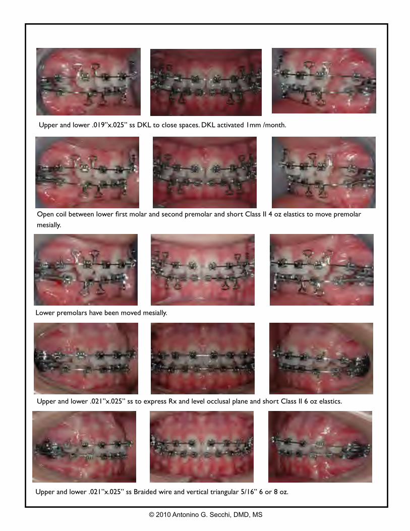
Open coil between lower first molar and second premolar and short Class II 4 oz elastics to move premolar
mesially.
Upper and lower .019”x.025” ss DKL to close spaces. DKL activated 1mm /month.
Lower premolars have been moved mesially.
Upper and lower .021”x.025” ss to express Rx and level occlusal plane and short Class II 6 oz elastics.
Upper and lower .021”x.025” ss Braided wire and vertical triangular 5/16” 6 or 8 oz.
© 2010 Antonino G. Secchi, DMD, MS
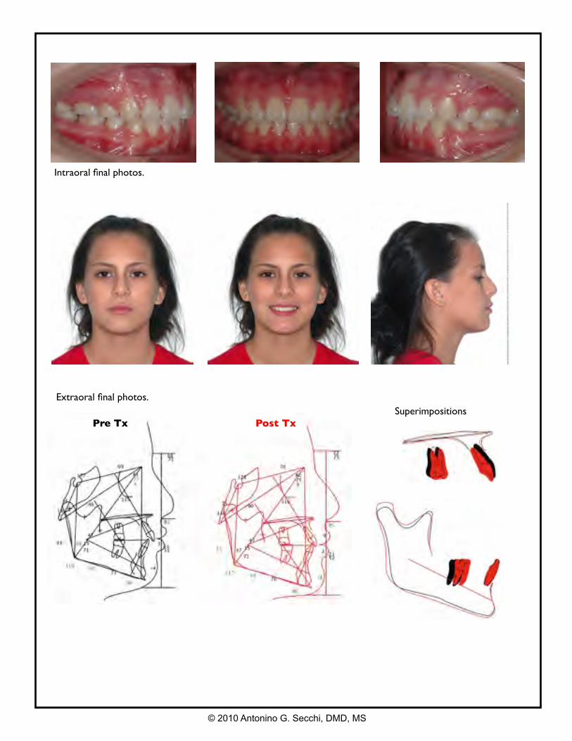
Extraoral final photos.
Intraoral final photos.
Pre Tx Post TxSuperimpositions
© 2010 Antonino G. Secchi, DMD, MS
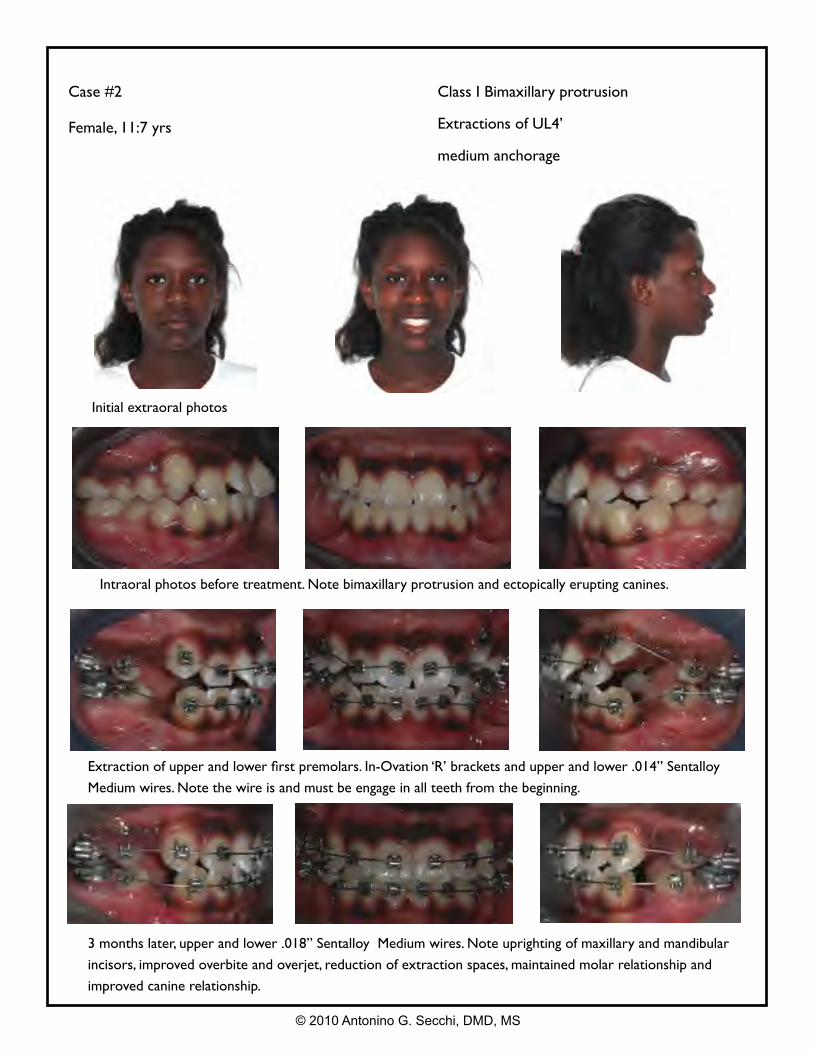
Case #2
Female, 11:7 yrs
Class I Bimaxillary protrusion
Extractions of UL4’
medium anchorage
Intraoral photos before treatment. Note bimaxillary protrusion and ectopically erupting canines.
Extraction of upper and lower first premolars. In-Ovation ‘R’ brackets and upper and lower .014” Sentalloy
Medium wires. Note the wire is and must be engage in all teeth from the beginning.
3 months later, upper and lower .018” Sentalloy Medium wires. Note uprighting of maxillary and mandibular
incisors, improved overbite and overjet, reduction of extraction spaces, maintained molar relationship and
improved canine relationship.
Initial extraoral photos
© 2010 Antonino G. Secchi, DMD, MS
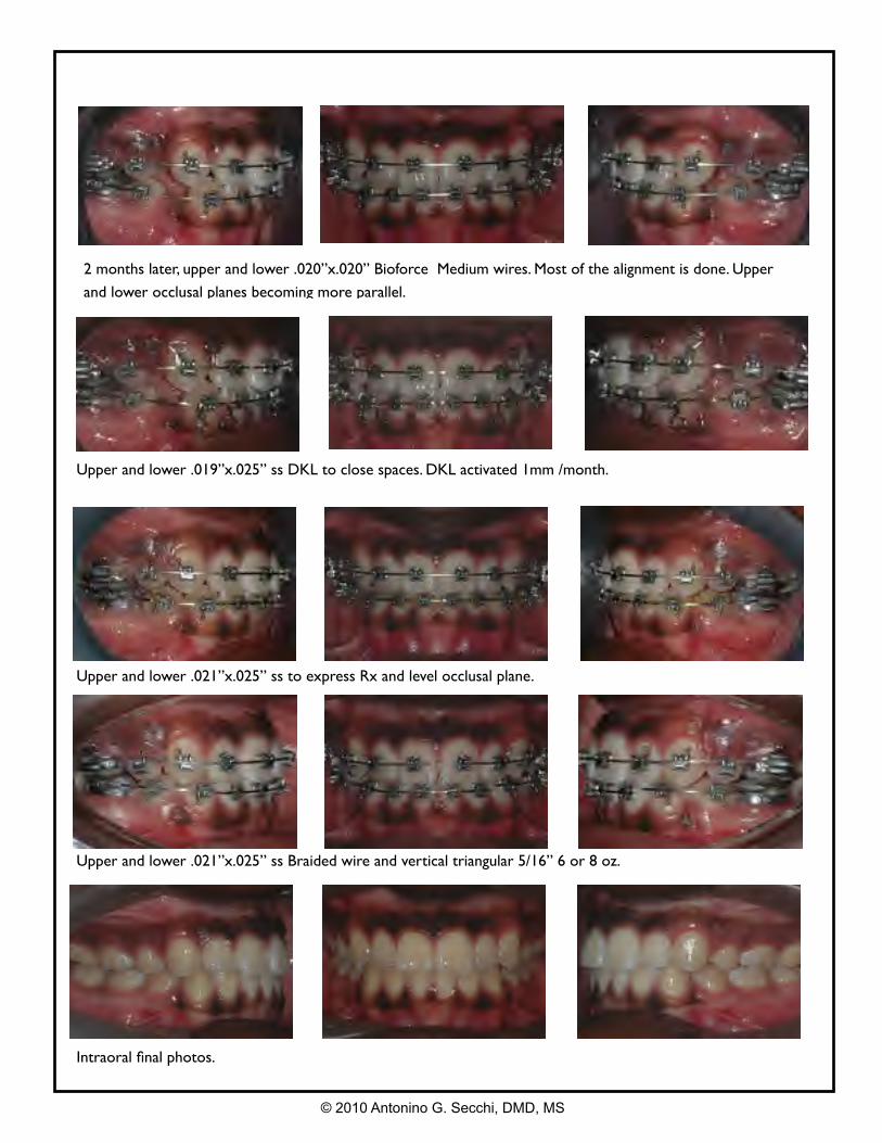
2 months later, upper and lower .020”x.020” Bioforce Medium wires. Most of the alignment is done. Upper
and lower occlusal planes becoming more parallel.
Upper and lower .019”x.025” ss DKL to close spaces. DKL activated 1mm /month.
Upper and lower .021”x.025” ss to express Rx and level occlusal plane.
Upper and lower .021”x.025” ss Braided wire and vertical triangular 5/16” 6 or 8 oz.
Intraoral final photos.
© 2010 Antonino G. Secchi, DMD, MS
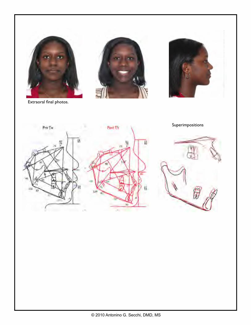
Extraoral final photos.
Superimpositions
© 2010 Antonino G. Secchi, DMD, MS
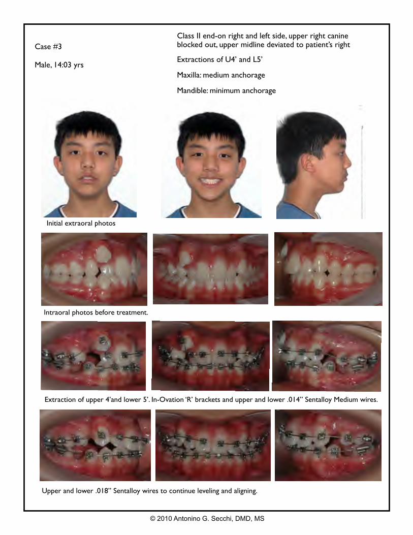
Case #3
Male, 14:03 yrs
Class II end-on right and left side, upper right canine blocked out, upper midline deviated to patient’s right
Extractions of U4’ and L5’
Maxilla: medium anchorage
Mandible: minimum anchorage
Intraoral photos before treatment.
Extraction of upper 4’and lower 5’. In-Ovation ‘R’ brackets and upper and lower .014” Sentalloy Medium wires.
Upper and lower .018” Sentalloy wires to continue leveling and aligning.
Initial extraoral photos
© 2010 Antonino G. Secchi, DMD, MS
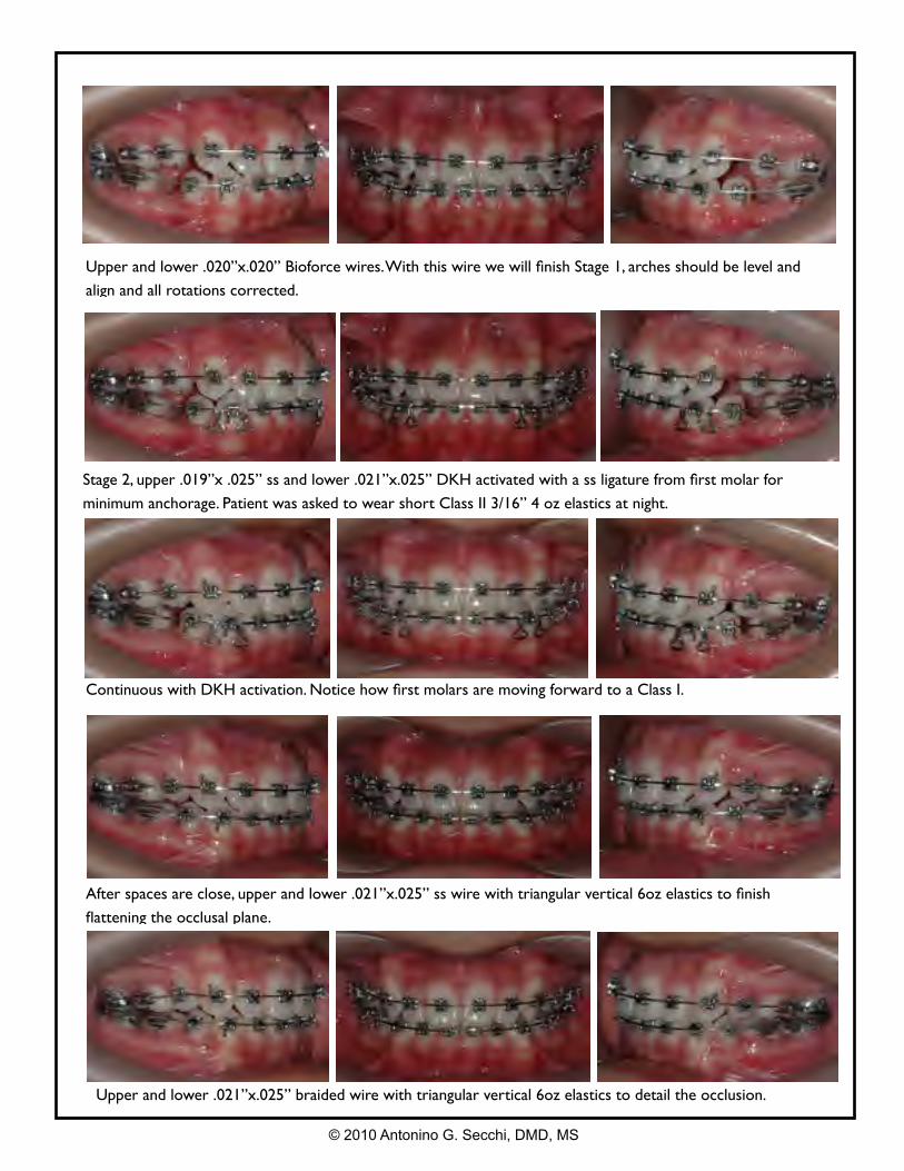
Stage 2, upper .019”x .025” ss and lower .021”x.025” DKH activated with a ss ligature from first molar for
minimum anchorage. Patient was asked to wear short Class II 3/16” 4 oz elastics at night.
Upper and lower .020”x.020” Bioforce wires. With this wire we will finish Stage 1, arches should be level and
align and all rotations corrected.
Continuous with DKH activation. Notice how first molars are moving forward to a Class I.
After spaces are close, upper and lower .021”x.025” ss wire with triangular vertical 6oz elastics to finish
flattening the occlusal plane.
© 2010 Antonino G. Secchi, DMD, MS
Upper and lower .021”x.025” braided wire with triangular vertical 6oz elastics to detail the occlusion.
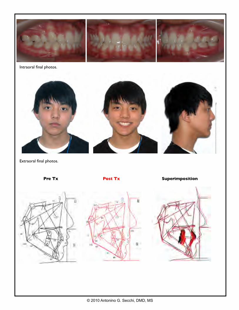
Extraoral final photos.
Pre Tx Post Tx Superimposition
© 2010 Antonino G. Secchi, DMD, MS
Intraoral final photos.
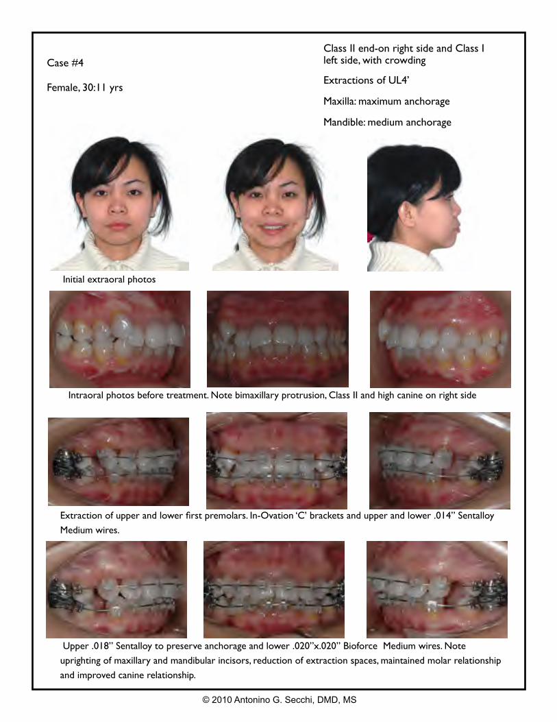
Case #4
Female, 30:11 yrs
Class II end-on right side and Class I left side, with crowding
Extractions of UL4’
Maxilla: maximum anchorage
Mandible: medium anchorage
Intraoral photos before treatment. Note bimaxillary protrusion, Class II and high canine on right side
Extraction of upper and lower first premolars. In-Ovation ‘C’ brackets and upper and lower .014” Sentalloy
Medium wires.
Upper .018” Sentalloy to preserve anchorage and lower .020”x.020” Bioforce Medium wires. Note
uprighting of maxillary and mandibular incisors, reduction of extraction spaces, maintained molar relationship
and improved canine relationship.
Initial extraoral photos
© 2010 Antonino G. Secchi, DMD, MS
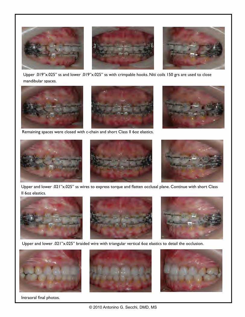
Remaining spaces were closed with c-chain and short Class II 6oz elastics.
Upper .019”x.025” ss and lower .019”x.025” ss with crimpable hooks. Niti coils 150 grs are used to close
mandibular spaces.
Upper and lower .021”x.025” ss wires to express torque and flatten occlusal plane. Continue with short Class
II 6oz elastics.
Upper and lower .021”x.025” braided wire with triangular vertical 6oz elastics to detail the occlusion.
Intraoral final photos.
© 2010 Antonino G. Secchi, DMD, MS
Extraoral final photos.
Pre Tx Post Tx Superimposition
© 2010 Antonino G. Secchi, DMD, MS
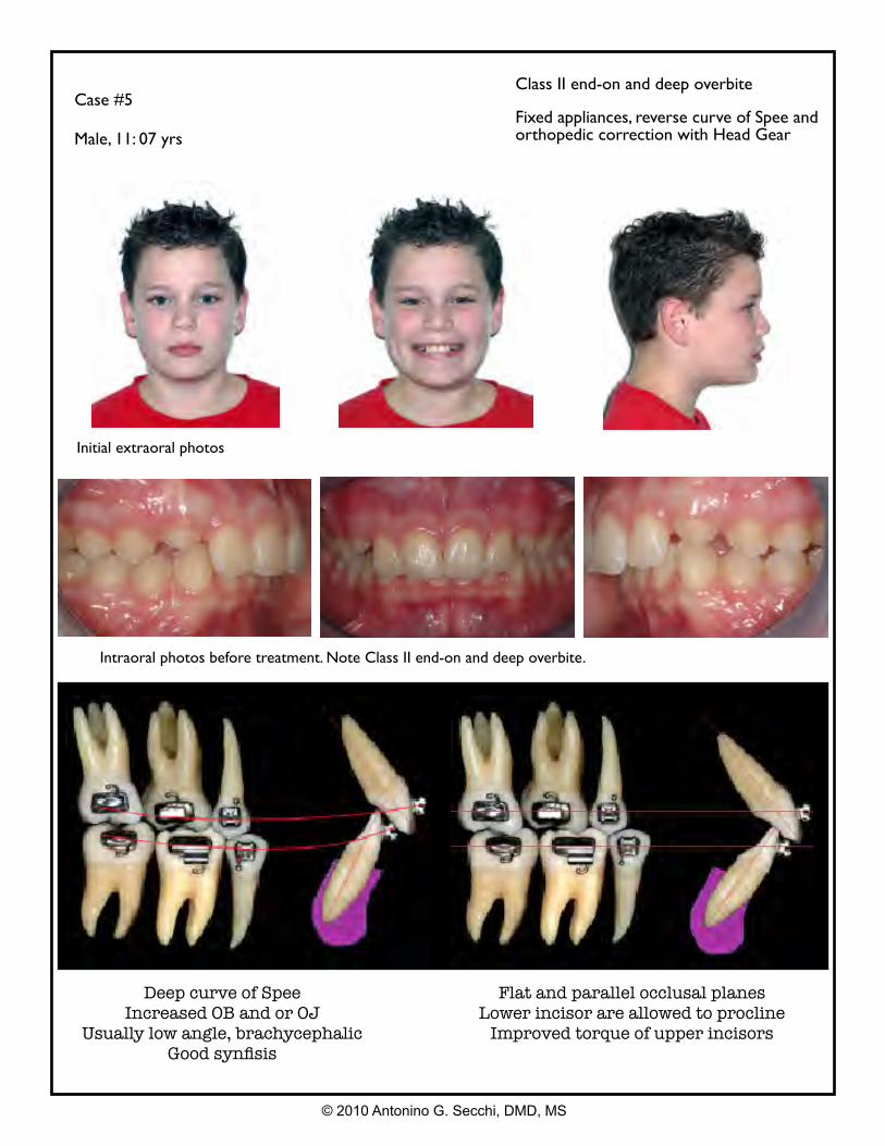
Case #5
Male, 11: 07 yrs
Class II end-on and deep overbite
Fixed appliances, reverse curve of Spee and orthopedic correction with Head Gear
Intraoral photos before treatment. Note Class II end-on and deep overbite.
Initial extraoral photos
© 2010 Antonino G. Secchi, DMD, MS
Deep curve of SpeeIncreased OB and or OJ
Usually low angle, brachycephalicGood synfisis
Flat and parallel occlusal planesLower incisor are allowed to procline
Improved torque of upper incisors
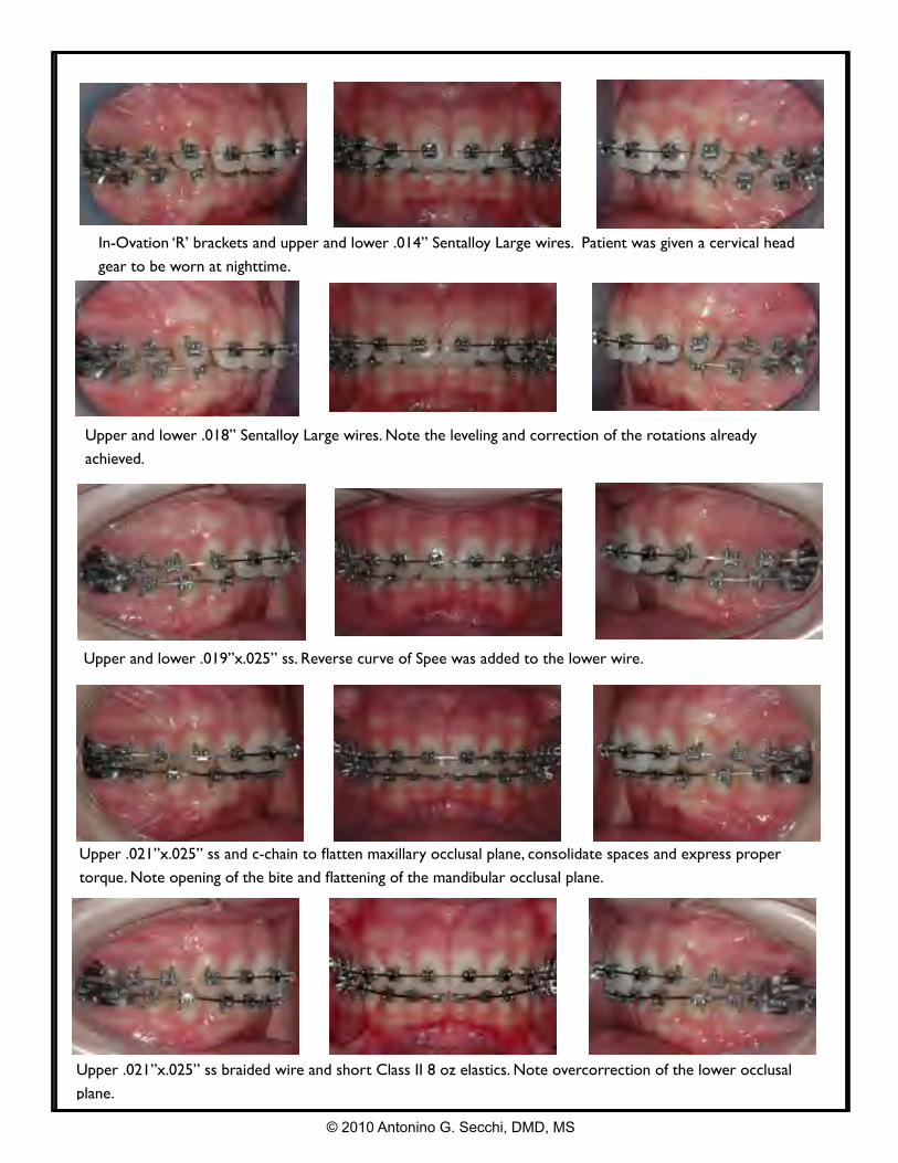
In-Ovation ‘R’ brackets and upper and lower .014” Sentalloy Large wires. Patient was given a cervical head
gear to be worn at nighttime.
Upper and lower .018” Sentalloy Large wires. Note the leveling and correction of the rotations already
achieved.
© 2010 Antonino G. Secchi, DMD, MS
Upper .021”x.025” ss and c-chain to flatten maxillary occlusal plane, consolidate spaces and express proper
torque. Note opening of the bite and flattening of the mandibular occlusal plane.
Upper and lower .019”x.025” ss. Reverse curve of Spee was added to the lower wire.
Upper .021”x.025” ss braided wire and short Class II 8 oz elastics. Note overcorrection of the lower occlusal
plane.
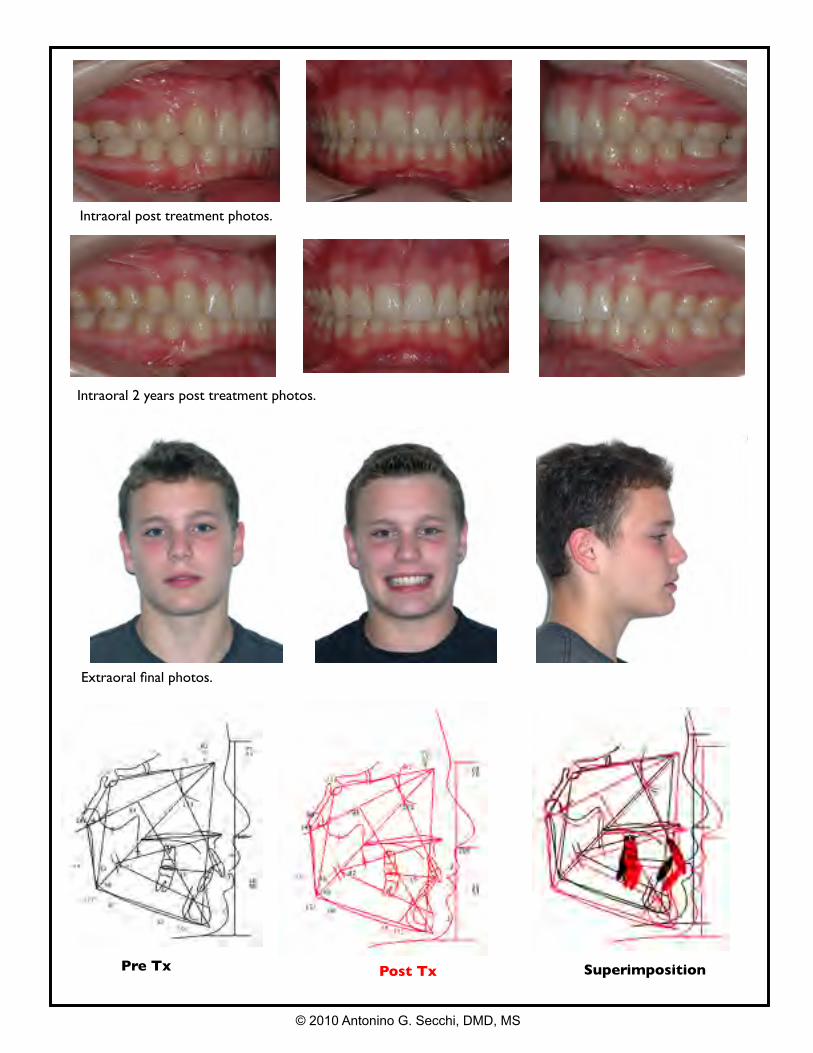
Intraoral post treatment photos.
Intraoral 2 years post treatment photos.
© 2010 Antonino G. Secchi, DMD, MS
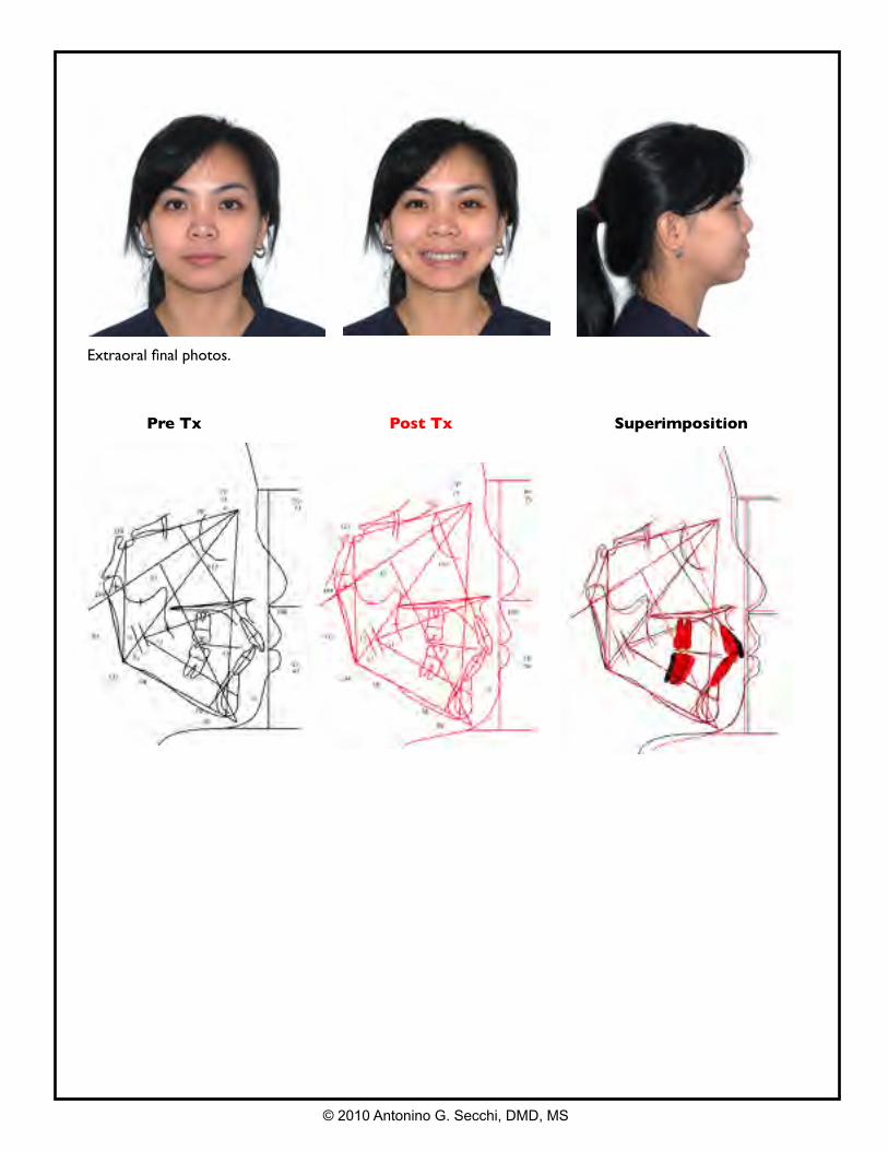
Extraoral final photos.
Pre Tx Post Tx Superimposition
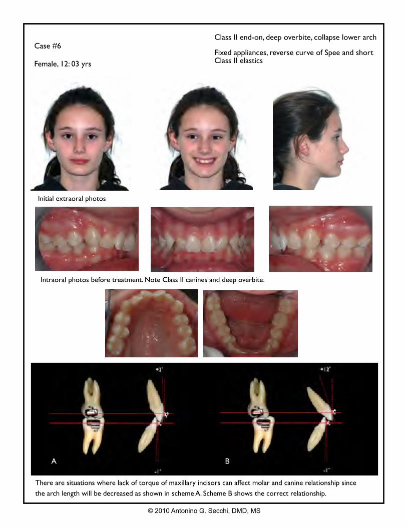
Case #6
Female, 12: 03 yrs
Class II end-on, deep overbite, collapse lower arch
Fixed appliances, reverse curve of Spee and short Class II elastics
Intraoral photos before treatment. Note Class II canines and deep overbite.
Initial extraoral photos
© 2010 Antonino G. Secchi, DMD, MS
There are situations where lack of torque of maxillary incisors can affect molar and canine relationship since
the arch length will be decreased as shown in scheme A. Scheme B shows the correct relationship.
A B
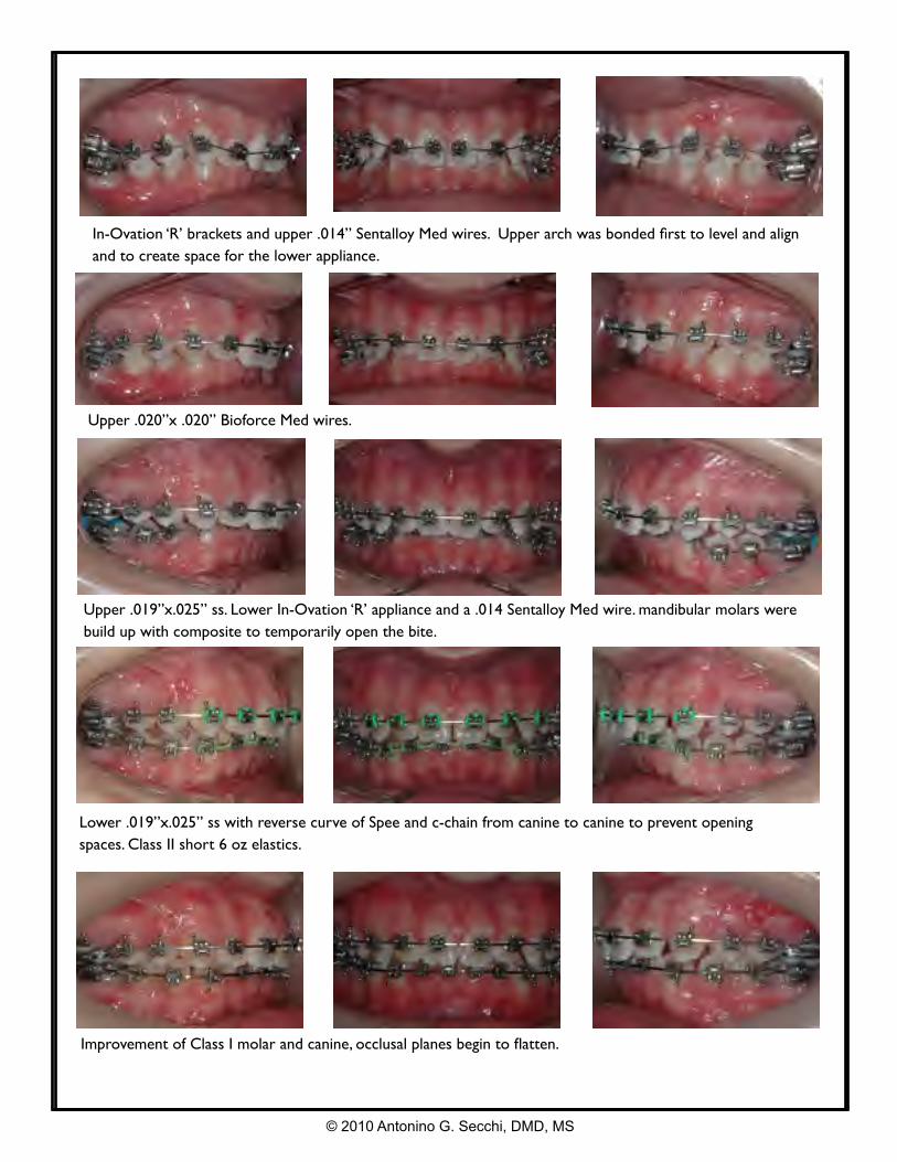
In-Ovation ‘R’ brackets and upper .014” Sentalloy Med wires. Upper arch was bonded first to level and align and to create space for the lower appliance.
Upper .020”x .020” Bioforce Med wires.
© 2010 Antonino G. Secchi, DMD, MS
Lower .019”x.025” ss with reverse curve of Spee and c-chain from canine to canine to prevent opening spaces. Class II short 6 oz elastics.
Upper .019”x.025” ss. Lower In-Ovation ‘R’ appliance and a .014 Sentalloy Med wire. mandibular molars were build up with composite to temporarily open the bite.
Improvement of Class I molar and canine, occlusal planes begin to flatten.
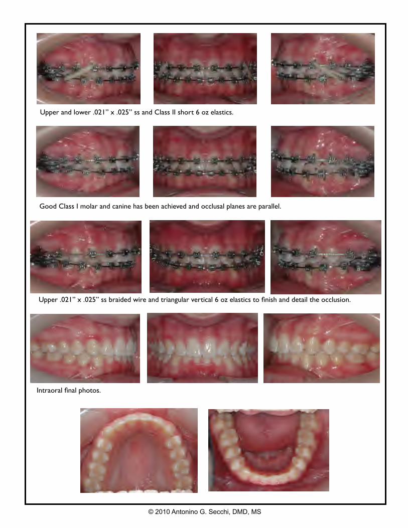
Upper and lower .021” x .025” ss and Class II short 6 oz elastics.
Good Class I molar and canine has been achieved and occlusal planes are parallel.
© 2010 Antonino G. Secchi, DMD, MS
Intraoral final photos.
Upper .021” x .025” ss braided wire and triangular vertical 6 oz elastics to finish and detail the occlusion.
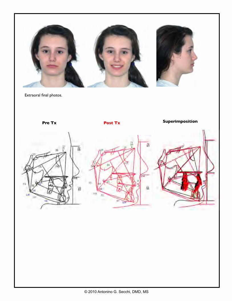
Pre Tx Post Tx Superimposition
© 2010 Antonino G. Secchi, DMD, MS
Extraoral final photos.
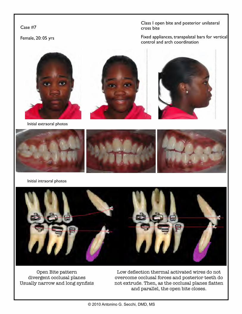
Case #7
Female, 20: 05 yrs
Class I open bite and posterior unilateral cross bite
Fixed appliances, transpalatal bars for vertical control and arch coordination
Initial extraoral photos
© 2010 Antonino G. Secchi, DMD, MS
Initial intraoral photos
Open Bite patterndivergent occlusal planes
Usually narrow and long synfisis
Low deflection thermal activated wires do not overcome occlusal forces and posterior teeth do not extrude. Then, as the occlusal planes flatten
and parallel, the open bite closes.
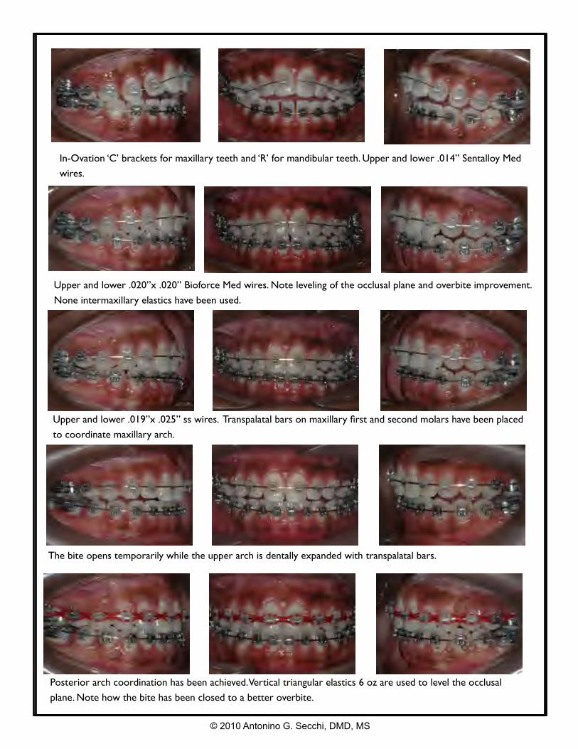
In-Ovation ‘C’ brackets for maxillary teeth and ‘R’ for mandibular teeth. Upper and lower .014” Sentalloy Med
wires.
Upper and lower .020”x .020” Bioforce Med wires. Note leveling of the occlusal plane and overbite improvement.
None intermaxillary elastics have been used.
© 2010 Antonino G. Secchi, DMD, MS
Upper and lower .019”x .025” ss wires. Transpalatal bars on maxillary first and second molars have been placed
to coordinate maxillary arch.
The bite opens temporarily while the upper arch is dentally expanded with transpalatal bars.
Posterior arch coordination has been achieved. Vertical triangular elastics 6 oz are used to level the occlusal
plane. Note how the bite has been closed to a better overbite.
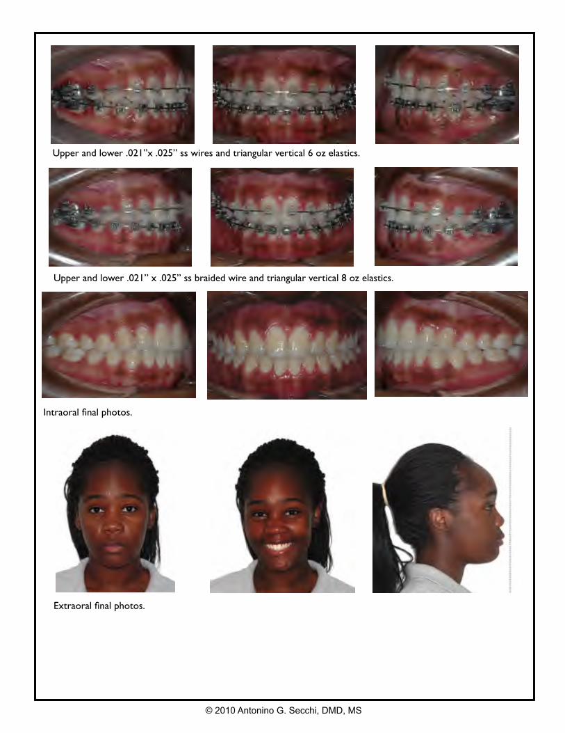
Upper and lower .021” x .025” ss braided wire and triangular vertical 8 oz elastics.
Upper and lower .021”x .025” ss wires and triangular vertical 6 oz elastics.
© 2010 Antonino G. Secchi, DMD, MS
Extraoral final photos.
Intraoral final photos.
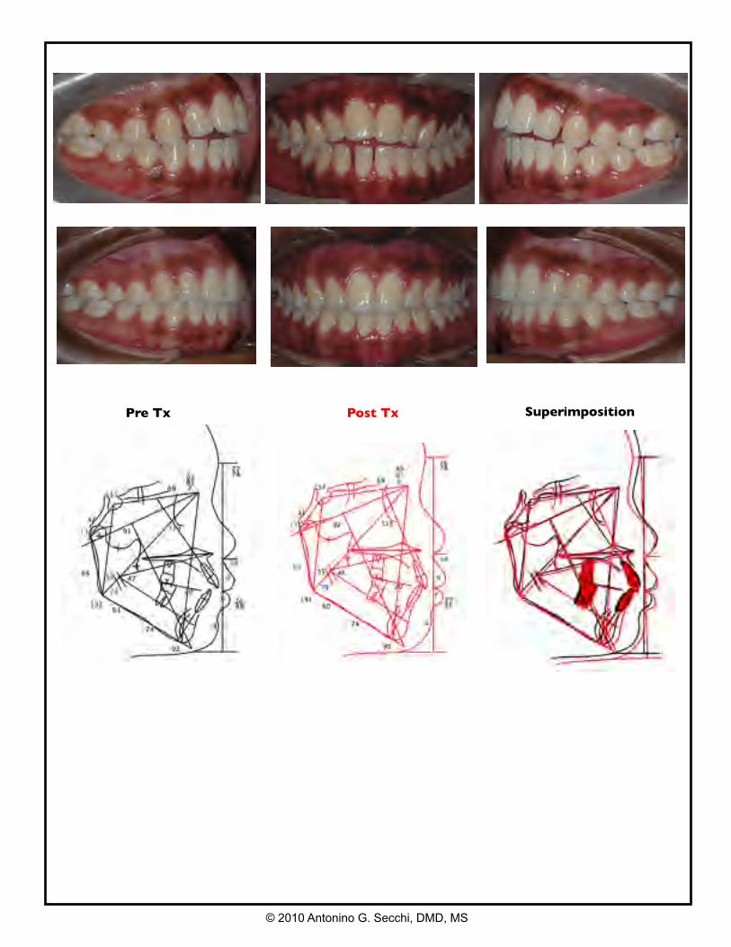
Pre Tx Post Tx Superimposition
© 2010 Antonino G. Secchi, DMD, MS
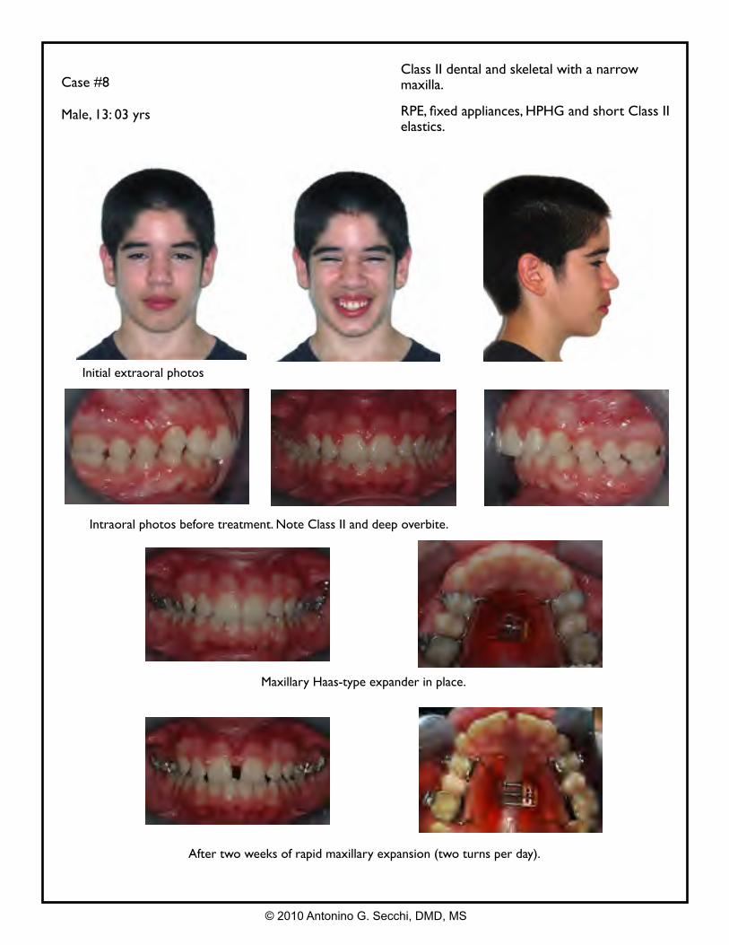
Case #8
Male, 13: 03 yrs
Class II dental and skeletal with a narrow maxilla.
RPE, fixed appliances, HPHG and short Class II elastics.
Intraoral photos before treatment. Note Class II and deep overbite.
Maxillary Haas-type expander in place.
After two weeks of rapid maxillary expansion (two turns per day).
Initial extraoral photos
© 2010 Antonino G. Secchi, DMD, MS
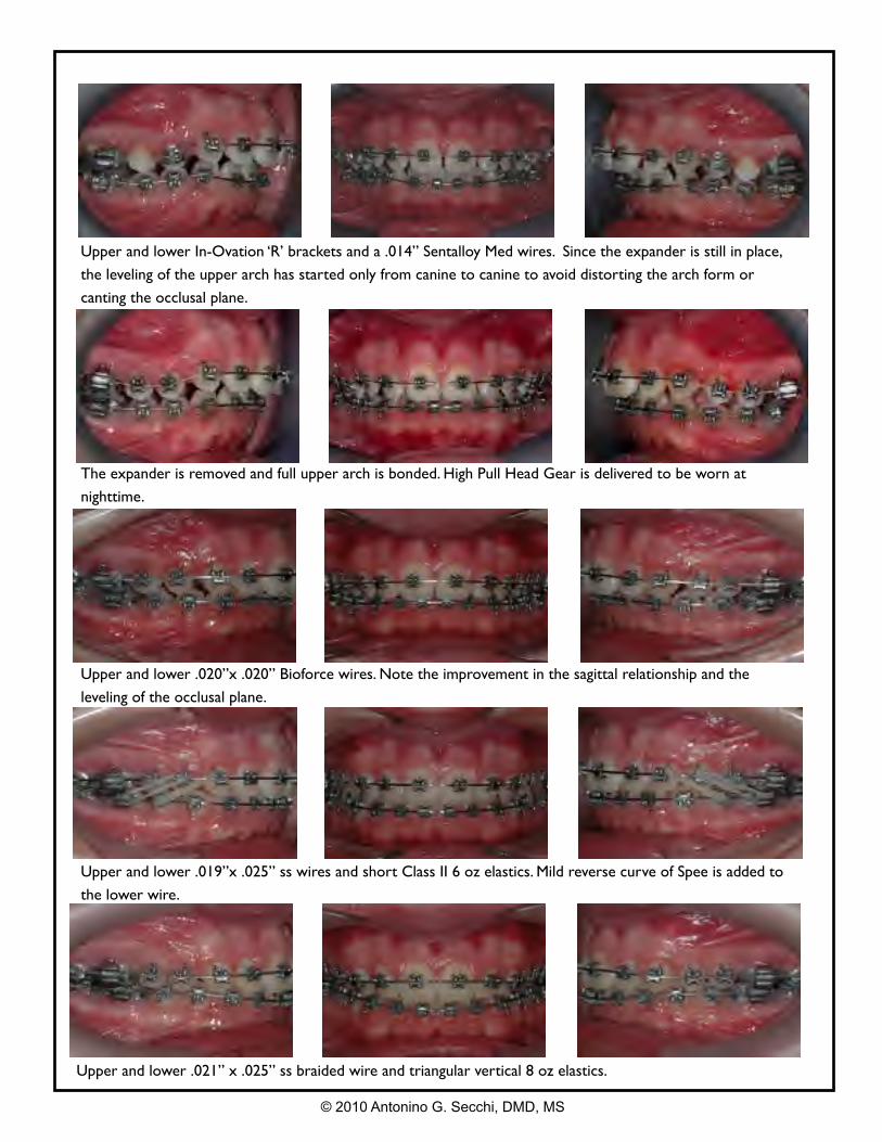
Upper and lower .021” x .025” ss braided wire and triangular vertical 8 oz elastics.
Upper and lower In-Ovation ‘R’ brackets and a .014” Sentalloy Med wires. Since the expander is still in place,
the leveling of the upper arch has started only from canine to canine to avoid distorting the arch form or
canting the occlusal plane.
The expander is removed and full upper arch is bonded. High Pull Head Gear is delivered to be worn at
nighttime.
Upper and lower .020”x .020” Bioforce wires. Note the improvement in the sagittal relationship and the
leveling of the occlusal plane.
Upper and lower .019”x .025” ss wires and short Class II 6 oz elastics. Mild reverse curve of Spee is added to
the lower wire.
© 2010 Antonino G. Secchi, DMD, MS
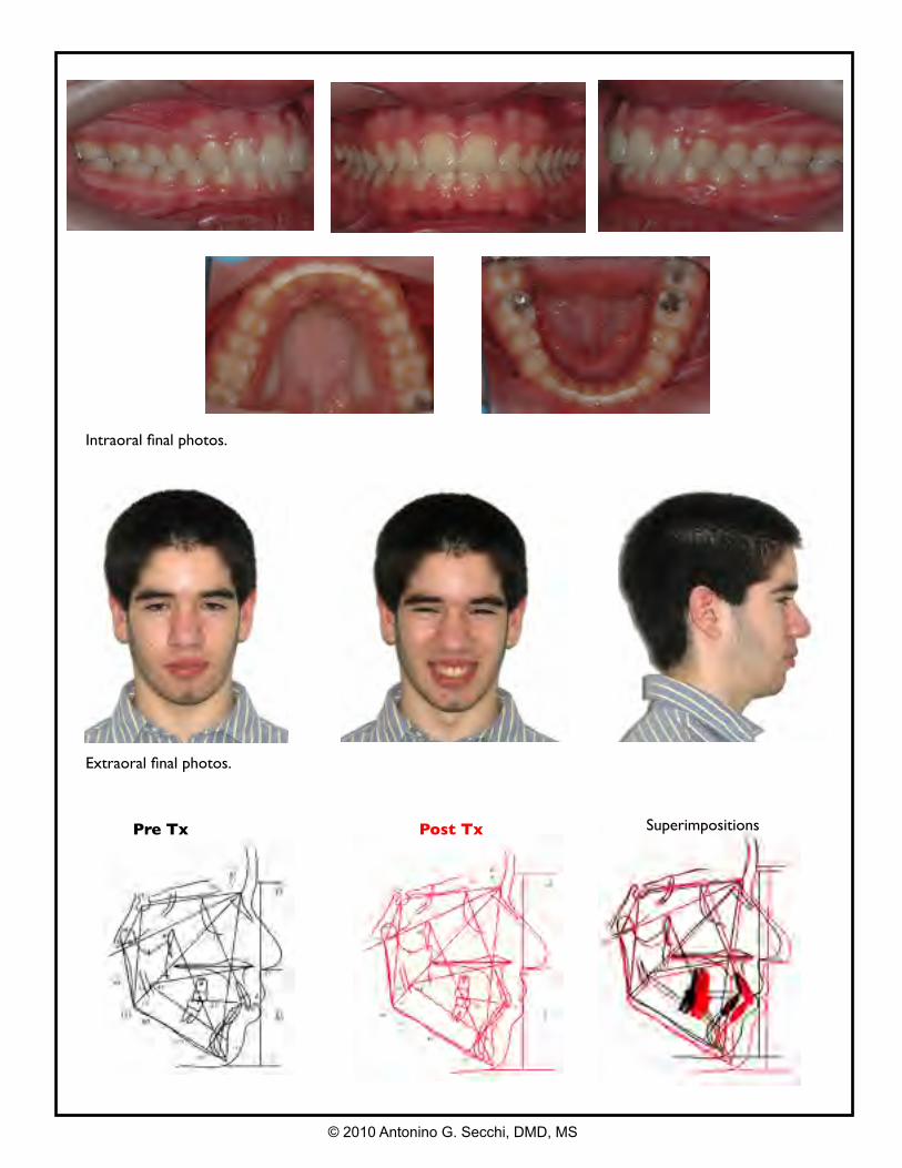
Extraoral final photos.
Intraoral final photos.
© 2010 Antonino G. Secchi, DMD, MS
Pre Tx Post Tx Superimpositions
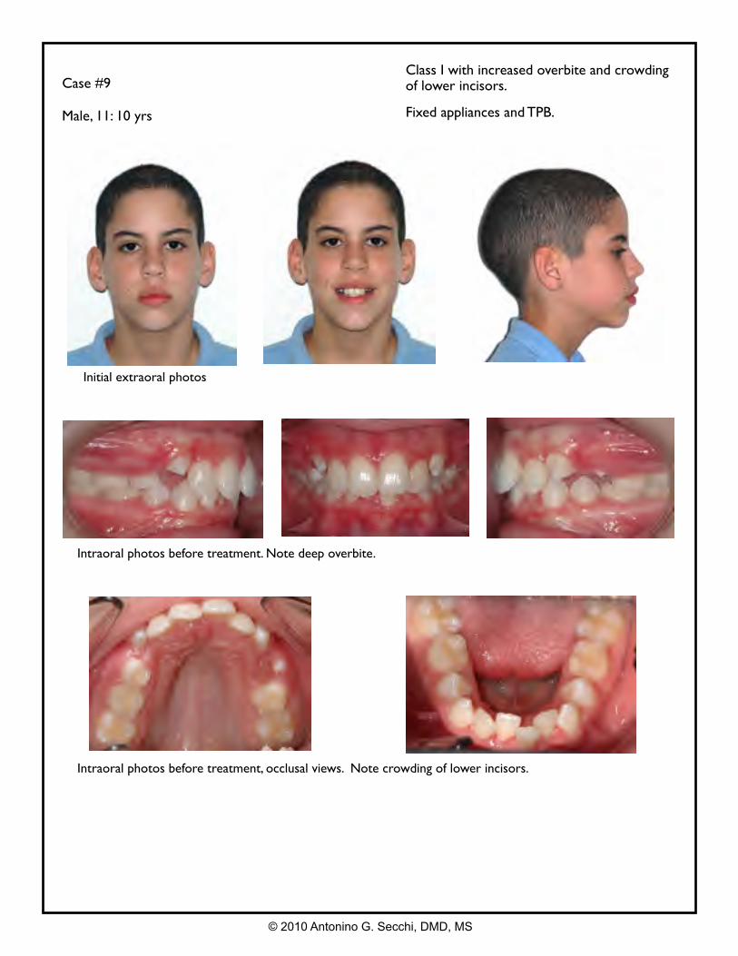
Case #9
Male, 11: 10 yrs
Class I with increased overbite and crowding of lower incisors.
Fixed appliances and TPB.
Intraoral photos before treatment. Note deep overbite.
Intraoral photos before treatment, occlusal views. Note crowding of lower incisors.
Initial extraoral photos
© 2010 Antonino G. Secchi, DMD, MS
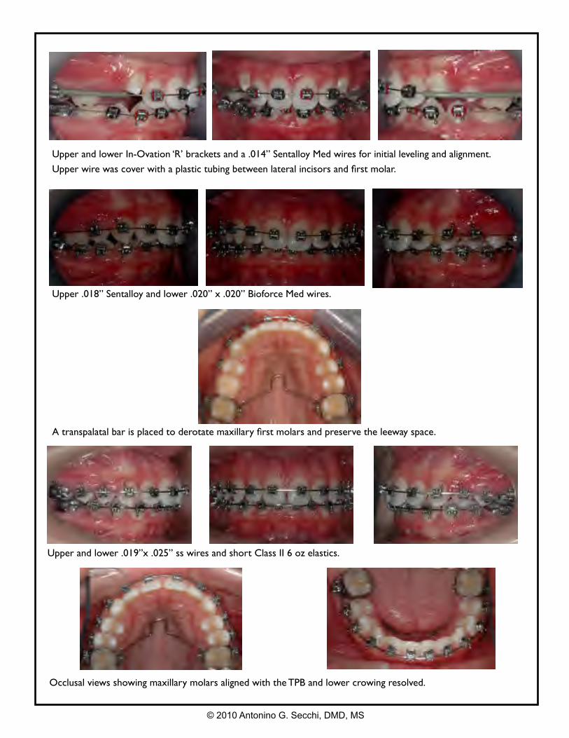
Occlusal views showing maxillary molars aligned with the TPB and lower crowing resolved.
Upper and lower In-Ovation ‘R’ brackets and a .014” Sentalloy Med wires for initial leveling and alignment.
Upper wire was cover with a plastic tubing between lateral incisors and first molar.
Upper .018” Sentalloy and lower .020” x .020” Bioforce Med wires.
A transpalatal bar is placed to derotate maxillary first molars and preserve the leeway space.
Upper and lower .019”x .025” ss wires and short Class II 6 oz elastics.
© 2010 Antonino G. Secchi, DMD, MS
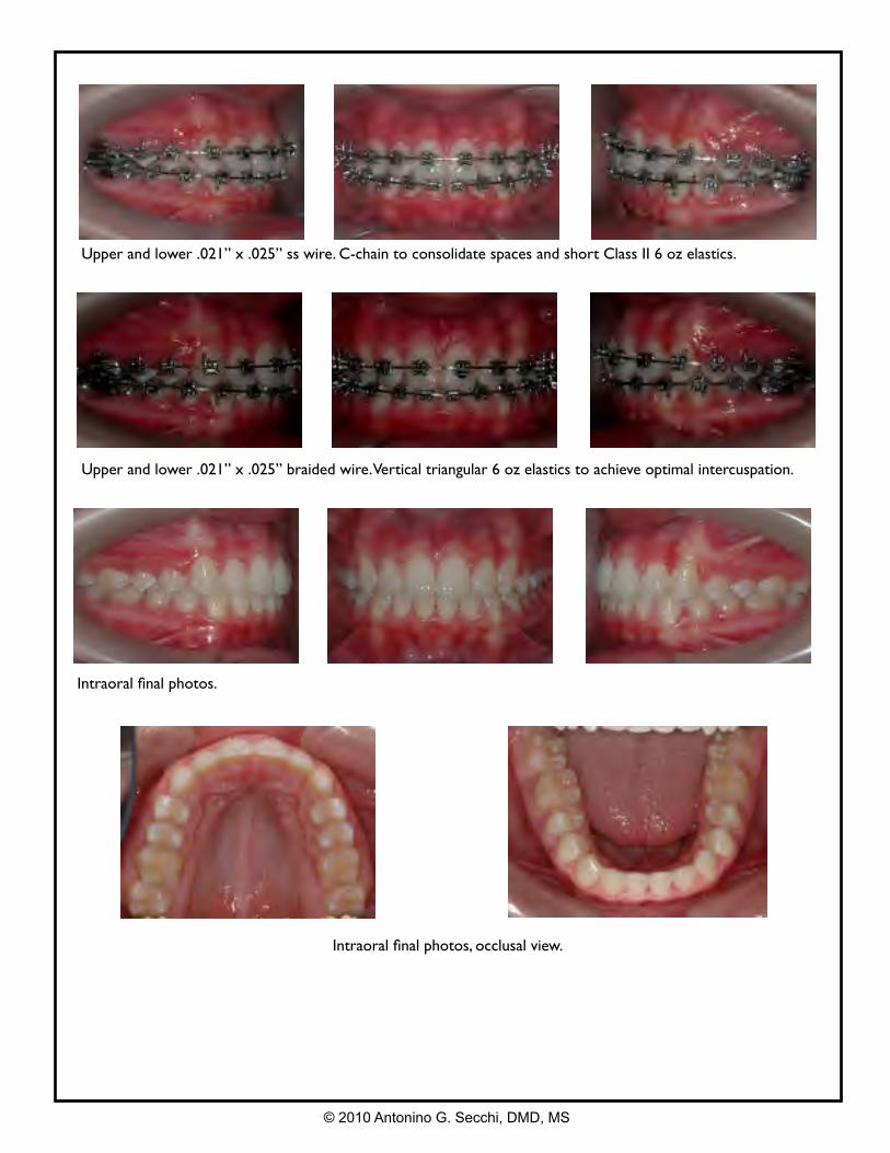
Upper and lower .021” x .025” ss wire. C-chain to consolidate spaces and short Class II 6 oz elastics.
Intraoral final photos.
Intraoral final photos, occlusal view.
Upper and lower .021” x .025” braided wire. Vertical triangular 6 oz elastics to achieve optimal intercuspation.
© 2010 Antonino G. Secchi, DMD, MS
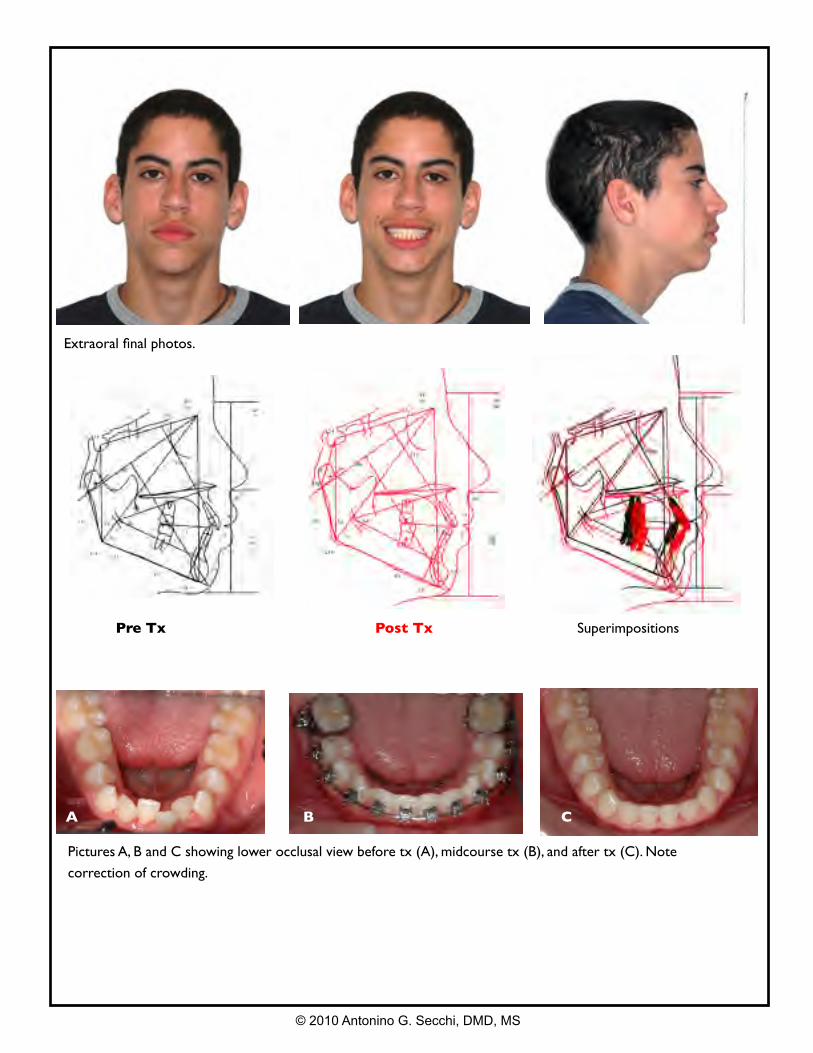
Extraoral final photos.
Pre Tx Post Tx Superimpositions
Pictures A, B and C showing lower occlusal view before tx (A), midcourse tx (B), and after tx (C). Note
correction of crowding.
A B C
© 2010 Antonino G. Secchi, DMD, MS
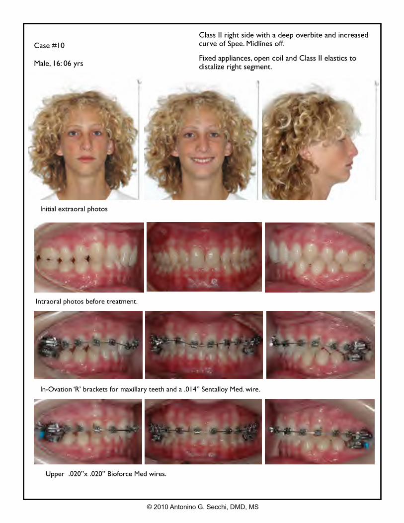
Case #10
Male, 16: 06 yrs
Class II right side with a deep overbite and increased curve of Spee. Midlines off.
Fixed appliances, open coil and Class II elastics to distalize right segment.
Intraoral photos before treatment.
In-Ovation ‘R’ brackets for maxillary teeth and a .014” Sentalloy Med. wire.
Upper .020”x .020” Bioforce Med wires.
Initial extraoral photos
© 2010 Antonino G. Secchi, DMD, MS
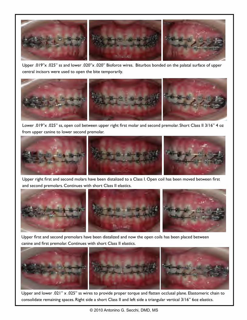
Upper and lower .021” x .025” ss wires to provide proper torque and flatten occlusal plane. Elastomeric chain to
consolidate remaining spaces. Right side a short Class II and left side a triangular vertical 3/16” 6oz elastics.
Upper .019”x .025” ss and lower .020”x .020” Bioforce wires. Biturbos bonded on the palatal surface of upper
central incisors were used to open the bite temporarily.
Lower .019”x .025” ss, open coil between upper right first molar and second premolar. Short Class II 3/16” 4 oz
from upper canine to lower second premolar.
Upper right first and second molars have been distalized to a Class I. Open coil has been moved between first
and second premolars. Continues with short Class II elastics.
© 2010 Antonino G. Secchi, DMD, MS
Upper first and second premolars have been distalized and now the open coils has been placed between
canine and first premolar. Continues with short Class II elastics.
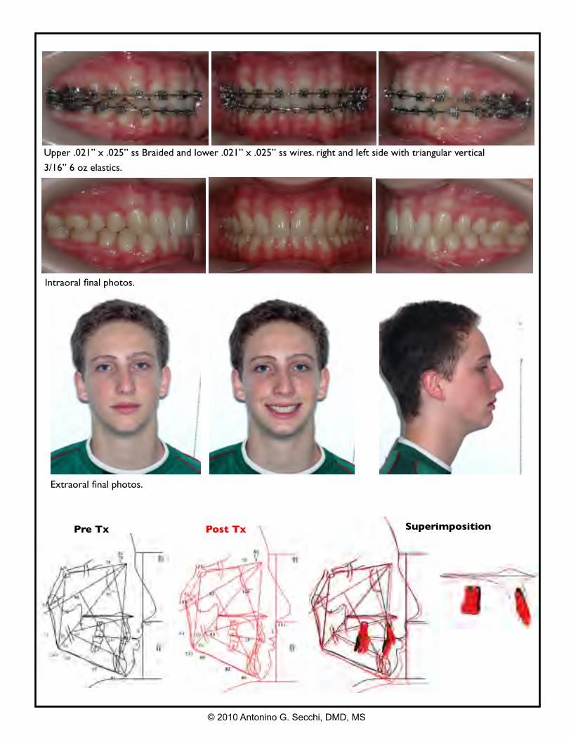
Extraoral final photos.
Intraoral final photos.
Pre Tx
© 2010 Antonino G. Secchi, DMD, MS
Post Tx Superimposition
Upper .021” x .025” ss Braided and lower .021” x .025” ss wires. right and left side with triangular vertical
3/16” 6 oz elastics.
The Author
Dr. Secchi is Assistant Professor of Orthodontics-Clinician Educator and Clinical Director of the Department of Orthodontics at the University of Pennsylvania, USA and Visiting Professor at the University of Los Andes, Chile. Dr. Secchi received his DDS from the University of Valparaiso, Chile; a Certificate in Advanced Occlusion from the University of Chile; and his DMD, Certificate in Orthodontics, and a Master of Science in Oral Biology from the University of Pennsylvania. Dr. Secchi is a Diplomate of the American Board of Orthodontics and member of the Edward H. Angle Society of Orthodontists. At the University of Pennsylvania, he has developed and implemented courses on Orthodontic Treatment Mechanics, Straight Wire Appliance Systems and Functional Occlusion in Orthodontics for postdoctoral orthodontic residents. He also provides didactic and clinical instruction for the predoctoral students and the Division of Graduate Dental Education. Dr. Secchi's research interests include, primarily, the relationship between self-ligating appliances, friction and treatment mechanics as well as orthodontics and functional occlusion. He has published in various dental and orthodontic peer review journals. He received the 2005 David C. Hamilton Orthodontic Research Award from the Pennsylvania Association of Orthodontists (PAO), a 2006 Orthodontic Faculty Development Fellowship Award from the American Association of Orthodontists Foundation (AAOF) and the 2007 Subtelny, Baker, Eastman Teaching Fellowship Award from the AAOF. His passion for clinical orthodontic and commitment to education have made him a solicited lecturer at a National and International level. In addition, he maintains an active orthodontic practice at the Dental Care Center of the University of Pennsylvania.
Antonino G. Secchi, DMD, MS
© 2010 Antonino G. Secchi, DMD, MS