Embed Size (px)
Citation preview
Complementary operating manual
Foundation Fieldbus
Operation and servicing instructions Part. no: 179810
Revision: 1.0
Date: 04/10/2018
Keep this manual for future reference. These operating manual is only valid in connection with the operating manual for i-matic.
Foundation Fieldbus Complementary Operating Manual
2
Important information
Notes:
• Please read operation instructions first!
• This manual must be kept for future use.
Purpose of the document:
This document contains information for commissioning, operation and maintenance staff. It is intended to support interoperability with DCS, local device operation and setting modifications.
Reference documents:
This operating manual has to be used in conjunction with the operating manual for i-matic actuators (from version 1.x)! Available via internet at www.drehmo.com.

Complementary Operating Manual Foundation Fieldbus
3
Table of contents
1 Safety instructions 5
1.1 General information on safety ............................................................................ 5
1.2 Range of application .......................................................................................... 6
1.3 Warnings and notes ........................................................................................... 6
2 General information regarding Foundation Fieldbus 7
2.1 Performance features ........................................................................................ 8
2.2 Layered communications model ......................................................................... 9
2.3 Physical layer .................................................................................................. 10
2.3.1 H1 Bus ................................................................................................ 10
2.3.2 High Speed Ethernet (HSE) ................................................................. 11
2.3.3 Connection between H1 and HSE ........................................................ 11
2.3.4 Data transmission and power supply .................................................... 11
2.4 Communication stack ...................................................................................... 11
2.4.1 Link Active Scheduler – LAS ................................................................ 12
2.4.2 Communication control ........................................................................ 12
2.4.3 Services .............................................................................................. 13
2.5 Application layer .............................................................................................. 15
2.5.1 Block model ........................................................................................ 15
2.5.2 Device descriptions ............................................................................. 16
2.5.3 System management ........................................................................... 17
2.5.4 System configuration ........................................................................... 17
2.6 Topology ......................................................................................................... 18
3 Electrical connection 21
3.1 General notes.................................................................................................. 21
3.2 Bus connection using socket connector ............................................................ 22
4 Commissioning 25
4.1 Introduction ..................................................................................................... 25
4.2 Installation of Device Description ..................................................................... 25
4.3 Network configuration ...................................................................................... 27
4.3.1 PD Tag and Node Address .................................................................. 27
4.4 Functionblocks ................................................................................................ 30
4.4.1 Operating Commands .......................................................................... 31
4.4.2 Feedback ............................................................................................ 31
5 Additional Functions 32
5.1 Data Channel .................................................................................................. 32
5.2 Simulation ....................................................................................................... 32
5.3 Redundancy .................................................................................................... 32
5.4 Firmware Update ............................................................................................. 32
6 Application Examples 33
6.1 General Information ......................................................................................... 33
6.1.1 Reset .................................................................................................. 33

Foundation Fieldbus Complementary Operating Manual
4
6.1.2 Download of the Function block application .......................................... 34
6.2 Drive the actuator for tests purposes ................................................................ 35
6.3 Control via discrete commands (single bit) ....................................................... 38
6.4 Control via discrete commands (multi bit) ......................................................... 44
6.5 Control via analog setpoint (without Automatic-Bit) ........................................... 50
6.6 Control via analog setpoint (with Automatic-Bit) ................................................ 56
6.7 Control with „Lock Local Control“ ..................................................................... 64
7 Description Foundation Fieldbus-Board 72
7.1 Notifications (optical signals) ........................................................................... 72
8 Technical data 73
Complementary Operating Manual Foundation Fieldbus
5
1 Safety instructions
1.1 General information on safety
Standards/
directives
DREHMO products are designed and manufactured in compliance with
recognized standards and directives.
The end user and contractor must sure about all legal requirements,
regulations, guidelines, national regulations and recommendations with
respect to assembly of the electrical connection, commissioning and
operation at the installation. For example these include configuration
guidelines for fieldbus applications.
Safety instructions-/
warnings
All personnel, who works with here described device, must be familiar and
keep with safety and warning instructions to avoid personal injury or property
damage.
Qualification
Only qualified personnel authorized by end user or contractor are allowed to
work with DREHMO products. Prior working the personnel must read and
understood this manual as well as know and respect recognized rules
regarding occupational health and safety. In explosive atmospheres has to
be observe special regulations. The end user and contractor of the plant are
responsible to keep and respect these special regulations.
Commissioning
Prior commissioning has to check that all settings meet their application
requirements. Incorrect settings can cause hazards to persons or equipment.
The manufacturer will not liable for any consequential damage. Such risk lies
entirely with the staff.
Operation
Requirements for safe and correct operation:
• Observe recognized rules regarding occupational health and safety.
• Report any faults and damage and eliminate it by a qualified staff.
• Operate DREHMO products only in a perfect condition and in compliance
with this manual.
• Correct transport, proper storage, positioning and assembly as well as
careful commissioning.
• Observe national regulations
Protective
measures
The end user or contractor is responsible for all necessary protective
measures on site, for example enclosures, barriers or protective equipment
for the staff.
Foundation Fieldbus Complementary Operating Manual
6
Changes
Changes on DREHMO devices only permitted by the approval of the
manufacturer.
Maintenance
The maintenance instructions must be observed, otherwise a safe operation
of the device is no longer guaranteed.
1.2 Range of application
DREHMO actuators are designed for the operation of industrial valves such as valves, gate valves,
butterfly valves and ball valves. Other applications require an explicit consult with the manufacturer.
The manufacturer will not liable for incorrect use and resulting possible damage. The risk is lying
with the user. Intended use includes the observance of these operating manuals.
1.3 Warnings and notes
Serious bodily injury or property damage can occur at non-observance of the warnings. Qualified
personnel must be thoroughly familiar with all warnings in this manual.
For highlight safety-relevant procedures in this manual, the following notes are marked with a
pictogram.
Note
This is general information for the user.
Information
This notice inform the user that non-observance can result in damage.
Warning
This notice inform the user that non-observance can possible result in
personal injury and property damage.
Danger
This notice inform the user that non-observance can result in serious
personal injury and property damage.
Danger
Info
Warning
Note

Complementary Operating Manual Foundation Fieldbus
7
2 General information regarding Foundation Fieldbus
For the exchange of information among automation systems and between
automation systems and the connected distributed field devices, the use of
serial fieldbus systems as communication system is state-of-the-art.
Thousands of applications have proved impressively that, in comparison with
conventional technology, cost savings of up to 40 % in wiring,
commissioning, and maintenance are achieved by using fieldbus technology.
While in the past the fieldbus systems used were often manufacturer specific
and incompatible with other bus systems, the systems employed today are
almost exclusively open and standardized. This means that the user does
not depend on individual suppliers and can choose within a large product
range the best product at the most competitive price.
Historical
development
In 1992, an international group, the ISP (Interoperable Systems Project) was
founded with the intention to create an internationally uniform fieldbus
standard for use in hazardous environments. At the same time, the
manufacturers and users of the French FIP (Flux Information Process;
previously: Factory Instrumentation Protocol) established the international
user organisation WorldFIP. Together with the FIP North America, they were
a strong counterweight to the ISP consortium. In 1994, for technical,
economic, and political reasons, the ISP and the WorldFIP merged to form
the Fieldbus Foundation. The aim of the Fieldbus Foundation was and is to
create a single, international fieldbus standard for hazardous environments
which will find widespread use as IEC standardised fieldbus.
User organisation
The Fieldbus Foundation is an independent non-profit organisation. The
mission is to develop and support a global, uniform fieldbus infrastructure for
automation tasks – the Foundation Fieldbus. Members include users and
manufacturers of field devices and automation systems. The Fieldbus
Foundation contains various workshops which are responsible, among
others, for technical support, marketing, and support of the members.
Website of the Fieldbus Foundation: www.fieldbus.org.
Certification of the
devices
This fieldbus is an open fieldbus standard which enables devices of different
manufacturers to be integrated in one system and, if required, ensures their
interchangeability (interoperability). This is only feasible when all devices
exactly meet the specification. If the devices are approved by Fieldbus
Foundation, this implies a guarantee for the user and manufacturer that
those devices comply with the specification.
Foundation Fieldbus Complementary Operating Manual
8
2.1 Performance features
The Foundation Fieldbus provides a broad spectrum of services and
functions compared to other fieldbus systems:
• Bus-powered field devices
• Line or tree topology
• Deterministic (predictable) dynamic behaviour
• Distributed data transfer (DDT)
• Standardised block model for uniform device interfaces (interoperability,
interchangeability)
• Trend functions and alarm treatment
• Flexible extension options based on device descriptions
• Intrinsic safety for use in hazardous areas (option)
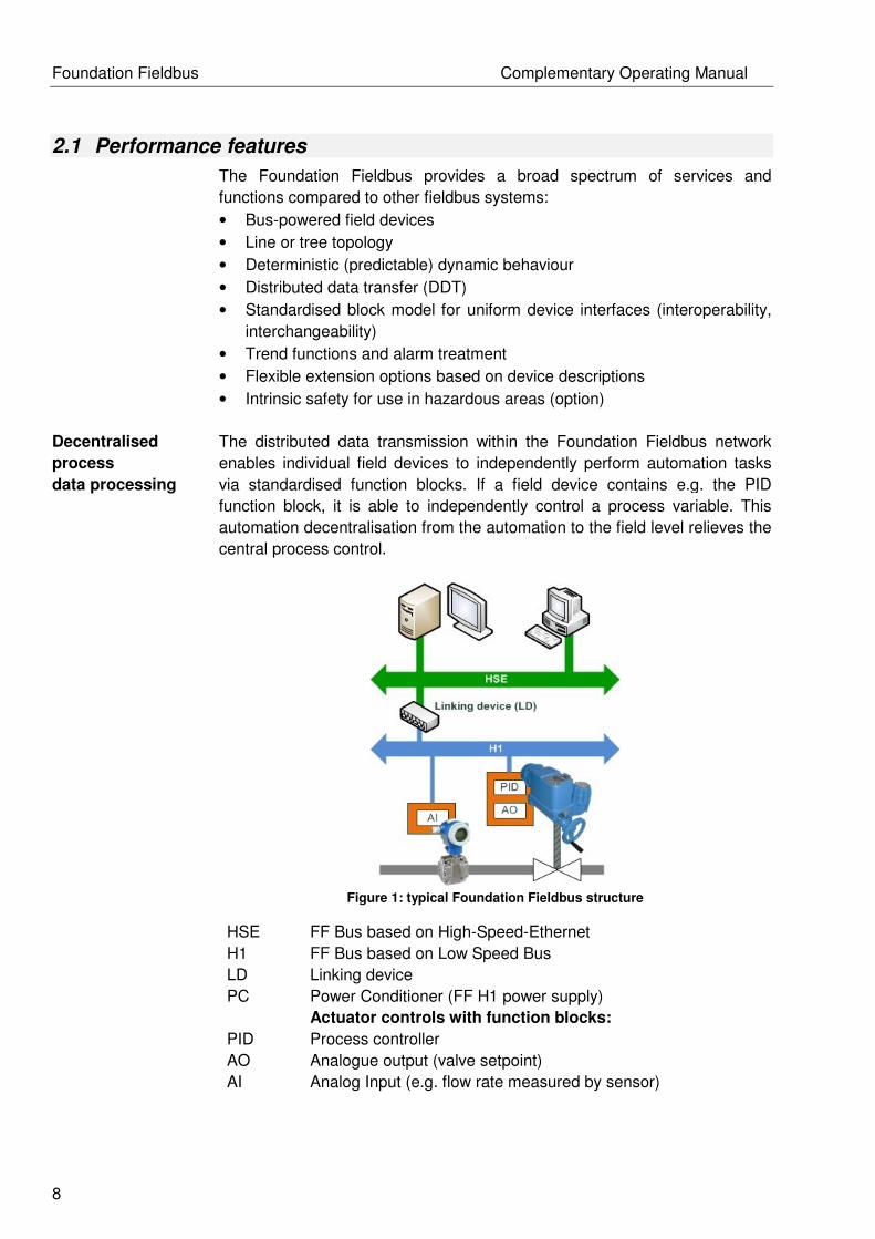
Decentralised
process
data processing
The distributed data transmission within the Foundation Fieldbus network
enables individual field devices to independently perform automation tasks
via standardised function blocks. If a field device contains e.g. the PID
function block, it is able to independently control a process variable. This
automation decentralisation from the automation to the field level relieves the
central process control.
Figure 1: typical Foundation Fieldbus structure
HSE FF Bus based on High-Speed-Ethernet
H1 FF Bus based on Low Speed Bus
LD Linking device
PC Power Conditioner (FF H1 power supply)
Actuator controls with function blocks:
PID Process controller
AO Analogue output (valve setpoint)
AI Analog Input (e.g. flow rate measured by sensor)

Complementary Operating Manual Foundation Fieldbus
9
2.2 Layered communications model
The structure of Foundation Fieldbus is based on the ISO/OSI reference
model (International Standards Organisation - Open Systems
Interconnection). This model consists of 7 layers. Foundation Fieldbus just
uses three layers:
• Layer 1: Physical layer
• Layer 2: Data link layer
• Layer 7: Application layer
As is the case for many other bus systems, layers three to six are not used.
Layer 7 is subdivided into a Fieldbus Access Sublayer (FAS) and a Fieldbus
Message Specification (FMS). The Communication Stack covers the tasks of
layers 2 and 7.
The special feature of Foundation Fieldbus is the device-dependent
application layer, placed above the 7th layer. Whereas the actual application
process is not determined for the ISO/OSI model, the Fieldbus Foundation
defines a special application layer. This layer contains a block model with
function block and a device description (DD). Depending on which blocks are
implemented in the block model of a device, users can access a variety of
services.
Thus, the Foundation Fieldbus specification consists of 3 main function
elements:
• Physical layer
• Communication stack
• Application layer
Figure 2: Compare OSI model vs. FF model

Foundation Fieldbus Complementary Operating Manual
10
2.3 Physical layer
The lowest bus level, the physical layer, is based on IEC standard 61158-2.
This layer defines how the physical connection to the fieldbus network as
well as the data transmission is to be performed.
Foundation Fieldbus uses two systems for the communication. The low H1
version for communication and direct connection of the field devices, the fast
HSE version based on Industrial Ethernet within the DCS and for connecting
Remote Operations Management (ROM) systems.
2.3.1 H1 Bus
The following summary gives a brief overview of the features and functions
of the H1 bus. For detailed information, refer to the various Application
Guides of the Fieldbus Foundation (e.g. AG-140, AG-163, AG-181, FD-043).
• Data transfer: Manchester coding
• Data transfer rate 31.25 kbit/s (default setting, cannot be modified).
• Requirements for perfect communication: Sufficient power supply for the
field devices, i.e. minimum 9 volts for each device. Software tools are
available for network planning, calculating the resulting currents and
terminal voltages on the basis of network topology, the cable resistance,
and the supply voltage. E.g. DesignMATETM, available via
www.fieldbus.org.
• Field device connection via H1 version. The Foundation Fieldbus Power
Conditioner is connected to the bus line in the same way (parallel) as a
field device. Field devices supplied by additional supply sources have to
be connected to these sources as well.
• The maximum power consumption of current consuming devices within
H1 networks must be lower than the electric power supplied by the
Foundation Fieldbus Power Conditioner.
• Network topologies: Line topology; when using junction boxes or
segment barriers, also star, tree or a combination of these topologies.
• Device connections: Typically via short spurs to enable
connection/disconnection of the devices without impairing communication
to other users.
• Maximum length of a spur: 120 m, depending on the number of spurs
used as well as the number of devices per spur.
• Maximum cable length of an H1 segment without repeater: 1,900 m.
• Maximum cable length of an H1 segment using maximum 4 repeaters: 5
x 1,900 m = 9.5 km. All spurs from the field devices to the junction boxes
have to be included in the total length calculation.
• Number of field devices per segment: In non-intrinsically safe areas:
Max. 32, in explosion-hazardous areas, this number is reduced to
significantly fewer devices (due to power supply limitations). Based on
the available H1 bandwidth, the typical number of devices per segment
is, however, max. 10 – 14 devices per segment.
Complementary Operating Manual Foundation Fieldbus
11
• Fieldbus cable: Type A (recommended), only this type is specified for the
maximum segment length of 1,900 m.
• Termination: Two terminators per bus segment, typically one at each end
of the longest fieldbus cable.
• Bus cable shielding: If shielded cables are used (recommended), the
shield is typically only earthed at one single point within the segment
(typically near the Foundation Fieldbus power supply). Apart from this,
other earthing philosophies are available (refer to AG-181).
2.3.2 High Speed Ethernet (HSE)
HSE is based on standard Ethernet technology. The required components
are widely used and are available at comparatively low costs. The HSE data
transfer speed runs at 100 Mbit/s and can be equipped with both copper
cables and optical fibre cables. The Ethernet operates by using random (not
deterministic) CSMA bus access.
This method cannot be applied to all automation applications, as for some
parts, real-time requirements have to be met. The extremely high
transmission rate enables the HSE to respond sufficiently fast when the bus
load is low and only few devices are connected. With respect to process
automation demands, real-time requirements are nevertheless met in any
case.
If the bus load must be reduced due to the multitude of connected devices,
or if several HSE sub networks are to be combined to create a larger
network, Ethernet switches must be used. A switch reads the target address
of the data packets that must be forwarded and then passes the packets on
to the associated sub network. This way, the bus load and the resulting bus
access time can be controlled to best adapt it to the respective requirements.
2.3.3 Connection between H1 and HSE
To connect the comparatively slow H1 segments to the HSE network, linking
devices (connecting devices) are required (refer to figure "Typical Foundation
Fieldbus structure" in chapter "Performance features").
The linking device adapts the data transfer rates and the data telegrams of
both networks while considering the direction of transmission. This way,
powerful and widely branched networks can be installed in larger plants.
2.3.4 Data transmission and power supply
Within the Foundation Fieldbus network, a device transmitting data typically
varies the power consumption by ±10 mA at 31.25 kBit/s to generate a
typical ± 0.5 V voltage change for power supply with 50 Ohm impedance.
This voltage variation is modulated onto the 9 – 32 V DC H1 power supply.
2.4 Communication stack
The field devices used with Foundation Fieldbus are capable of
independently assuming automation tasks, i.e.:

Foundation Fieldbus Complementary Operating Manual
12
• Each field device can directly exchange data with other devices (e.g.
reading measuring values, forwarding control values).
• All field devices send and receive data at pre-defined points in time.
• Specific mechanism ensures that never two or more devices
simultaneously access the bus.
To meet these requirements, the Foundation Fieldbus needs a central
communication control system (Link Active Scheduler = LAS).
2.4.1 Link Active Scheduler – LAS
A field device performing the Link Active Scheduler (LAS) function controls
and schedules the bus communication. It controls all bus activities by means
of specific data telegrams that it sends to the available devices. Since the
LAS also continuously polls unassigned device addresses, it is possible to
connect devices during operation and to integrate them in the bus
communication.
Devices which can be used as LAS are called Link Master Devices (LM).
Basic devices (BD) do not have LAS capacity.
In a redundant system containing several link master devices, only one link
master takes over the LAS task. If the active LAS device fails, another link
master device will take over (fail-operational design).
The LAS ensures both updating and continuous transmission of the Live List
to all other Link Master Devices. If a device is removed from or added to the
list, the LAS transmits this change to all link master devices (broadcast
message). This way, all link masters have access to the current live list so
that they can become the LAS without any loss of information, if required.
2.4.2 Communication control
The communication services of the FF specification define both scheduled
and unscheduled data transmission. Time-critical tasks, such as the control
of process variables, are exclusively performed by scheduled services,
whereas programming and diagnostic functions are carried out using
unscheduled communication services.
Scheduled data
transmission
To solve communication tasks in time and without access conflicts, all time-
critical tasks are based on a defined transmission schedule. The pertaining
definitions are created by the Foundation Fieldbus system operator during
the configuration of the FF system.
The LAS periodically broadcasts a time synchronisation signal (TD: Time
Distribution) on the fieldbus so that all devices have exactly the same data
link time. In scheduled transmission, the point in time and the sequence of
data telegrams are defined in detail.
For this reason, the FF H1 system is also called deterministic fieldbus
system.
For each action to be performed (e.g. execution of a function block or
transmission of a process value), a defined period is added to the schedule.
Based on this schedule, a transmission list is generated which defines when
a specific field device is prompted to send its data. Upon receipt of a special

Complementary Operating Manual Foundation Fieldbus
13
trigger telegram (CD: Compel Data), the respective device (publisher)
broadcasts the data in the reception buffer of all devices which are
configured to receive this data (subscriber).
This type of transmission is therefore called the “publisher-subscriber”
method.
Unscheduled data
transmission
Device parameters and diagnostic data are typically only transmitted when
needed, i.e. on request. The transmission of this data is not time-critical. For
such communication tasks, the Foundation Fieldbus offers unscheduled data
transmission.
Permission for a certain device to use the fieldbus for unscheduled
communication tasks is granted by the LAS device, provided that no
scheduled data transmission is active.
Every device may use the bus as long as required until it either returns the
bus access right (token), or until the maximum granted time to use the token
has elapsed.
Unscheduled transmission offers two data transmission methods: “Client
Server” to adapt device settings, configuration upload/download of diagnostic
data as well as "Report Distribution" to send alarms.
2.4.3 Services
The Fieldbus Access Sublayer (FAS) and the Fieldbus Message
Specification (FMS) layer form the interface between the data link layer and
the user application (refer to figure 2). The services provided by both FAS
and FMS are invisible for the user.
However, performance and functionality of the communication system
considerably depend on these services.

Foundation Fieldbus Complementary Operating Manual
14
Fieldbus Access
Sublayer (FAS)
The FAS services create Virtual Communication Relationships (VCR) which
are used by the higher-level FMS layer to execute its tasks. VCRs describe
different types of communication processes and enable faster processing of
the associated activities. Foundation Fieldbus communication uses the three
different VCR types as follows (refer to table).
Client/Server Report Distribution Publisher/Subscriber
User communication Events, alarms, trends Process data
transmission
Setpoint changes,
operating data and
device data changes,
upload/download,
alarm value
adaptation, remote
diagnostics.
Send process alarms
to user consoles,
transmitting trend data
for long term data
logging
Transfer process
values of sensors and
other devices
Unscheduled Unscheduled Scheduled
Table 1: Fieldbus Access Sublayer
The Publisher/Subscriber VCR type is used to transmit the input and output
data of function blocks. As described above, scheduled data transmission is
based on this type of VCR.
The Client/Server VCR type is the basis for operator initiated requests, such
as setpoint changes, adaptations and change of control parameters,
diagnostics, device upload, and download, etc.
Report Distribution is used to send alarms or event notifications to the user
console or similar devices. Client/Server and Report Distribution data
transmission is unscheduled, due to the fact that the time of transmission
cannot be foreseen and therefore not be scheduled.
Fieldbus Message Specification (FMS)
The FMS provides the services for standardised communication. Data types
that are communicated via the fieldbus are assigned to certain
communication services. For uniform and clear assignment, object
descriptions are used. Object descriptions contain definitions of all standard
transmission message formats as well as application-specific data. Special,
predefined communication services are available for each object type.
Object descriptions are collected together in a structure called an object
dictionary.
Complementary Operating Manual Foundation Fieldbus
15
2.5 Application layer
An important criterion for a fieldbus system to be accepted by the market is
the interoperability of the devices. Interoperability characterises the capability
of devices of different manufacturers to communicate with each other. In
addition, it must be ensured that a device from one manufacturer can be
substituted with that of another.
This requires an open protocol specification which defines uniform device
functions and application interfaces. Other network users and application
programs can use these interfaces to access the functions and parameters
of the field devices. The Foundation Fieldbus meets these requirements by
means of standardised function blocks and device descriptions.
2.5.1 Block model
Foundation Fieldbus assigns all functions and device data to three different types of
blocks:
• Resource block
• One or several function blocks
• Several transducer blocks
Resource block The resource block describes characteristics of a fieldbus device, e.g. device
name, manufacturer, serial number, hardware and firmware version, etc.

Foundation Fieldbus Complementary Operating Manual
16
Function blocks Function blocks describe the device functions and define how these can be
accessed. The charts of scheduled data transmission are based on these
function blocks. Each block (including the pertaining inputs and outputs) has
a definite task. Each FF device is equipped with at least one function block.
The FF specification provides defined function blocks which can be used to
describe the typical functions. They are listed below:
AI Analog Input
AO Analog Output
DI Discrete Input
DO Discrete Output
PID Proportional/integral/derivative
SC Signal Characteriser
IS Input Selector
Table 2: Functionblocks
Transducer blocks Transducer blocks enhance the application options of a device. Their data
enables the input and/or output parameters of a function block to be
influenced. Measuring and positioning data can be calibrated and reset,
characteristics can be linearized or physical units can be reset using
additional process data.
Further objects Besides the three block types, the following additional objects are defined
within the block model:
Link objects define the connections between different function blocks, both
internal to the field device as well as across the fieldbus network.
Alert objects allow reporting alarms and events on the fieldbus. Trend objects
allow trending function block data for access and analysis from higher-level
systems.
View objects are predefined groupings of data and block parameter sets that
can be used to group and display the parameters according to their tasks:
Process control, configuration, maintenance and additional information.
2.5.2 Device descriptions
During start-up and maintenance as well as when performing diagnostic
functions, an open communication system must ensure that higher-level
control computers or control systems can access all field devices and that
respective controls are available.
The device descriptions (DDs) contain the necessary information to fulfil
these requirements. They provide all information needed to understand the
meaning of the device data and display them correctly on the operator
console

Complementary Operating Manual Foundation Fieldbus
17
2.5.3 System management
The system management of each device has the following tasks:
• Synchronisation of device activities in compliance with the predefined
transmission schedule
• Cyclical processing of transmission list (LAS only) within the predefined
schedule.
Further tasks performed by the system management:
• Automatic assignment of LAS functions to another Link Master if the
active LAS fail.
• Synchronisation of clock information
• Automatic address assignment for new devices within the communication
network
The automatic assignment of a provisional device address allows the
assignment of a clear and unambiguous device address at the
commissioning during active communication. For this address assignment
procedure, special default addresses are reserved allowing accessing the
new devices which are not yet configured. A new device is integrated in the
communication network after assigning a device tag as well as a new, clear,
unambiguous node address. The default address used is then available
again for the assignment of further devices, still due to be configured.
2.5.4 System configuration
Scheduled communication as well as all fieldbus devices must be configured
before their first start-up (refer to figure below). This requires a configuration
tool, e.g. the NI-FBUS Configurator by National Instruments.
Figure 3: FF-Network
1 Configuration device
2 Configurating basic devices
3 Configurating LAS and link master
Foundation Fieldbus Complementary Operating Manual
18
Prior to the actual commissioning, the Device Descriptions (DD) for all
devices to be configured must be entered using configuration tools. The
configuration software must either be able to access the device descriptions
in the available libraries, or the device descriptions must be loaded via
external data storage devices.
The configuration software helps to determine how and with which devices
the measurement and control tasks of a plant are processed by connecting
the function blocks of the field devices. This task can be performed using a
graphical user interface. For this, just connect inputs and outputs of the
corresponding block symbols and define the block behaviour.
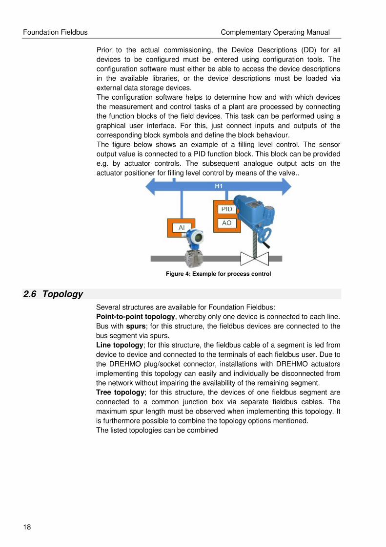
The figure below shows an example of a filling level control. The sensor
output value is connected to a PID function block. This block can be provided
e.g. by actuator controls. The subsequent analogue output acts on the
actuator positioner for filling level control by means of the valve..
Figure 4: Example for process control
2.6 Topology
Several structures are available for Foundation Fieldbus:
Point-to-point topology, whereby only one device is connected to each line.
Bus with spurs; for this structure, the fieldbus devices are connected to the
bus segment via spurs.
Line topology; for this structure, the fieldbus cable of a segment is led from
device to device and connected to the terminals of each fieldbus user. Due to
the DREHMO plug/socket connector, installations with DREHMO actuators
implementing this topology can easily and individually be disconnected from
the network without impairing the availability of the remaining segment.
Tree topology; for this structure, the devices of one fieldbus segment are
connected to a common junction box via separate fieldbus cables. The
maximum spur length must be observed when implementing this topology. It
is furthermore possible to combine the topology options mentioned.
The listed topologies can be combined

Complementary Operating Manual Foundation Fieldbus
19
Figure 5: Topologie
1 DCS
2 Trunk
3 Spurs
JB Junction Box
Spurs or tee connectors are possible for Foundation Fieldbus. The possible
fieldbus line length is determined by the type of cable, the cross section, and
the type of the bus supply.
Cable length = trunk length + total spur length
Maximum length = 1,900 metres with cable type A
By using up to four repeaters, a maximum of 5 x 1,900 m = 9,500 m can be
achieved.
A terminator is to be installed at both ends of the main trunk.
Number of devices Permissible spur length
The number of devices possible on
a fieldbus depends on the power
consumption of devices, the type of
cable used, the use of repeaters,
etc. For details please refer to
Physical Layer Standard.
Permissible spur length for one
device per spur - any further device
reduces the permissible spur length
by 30 metres
25-32 1 m
19 – 24 30 m
15 – 18 60 m
13 – 14 90 m
1 – 12 120 m
Table 3: Spurlength according number of devices

Foundation Fieldbus Complementary Operating Manual
20
For details regarding the different topology options, please refer to the
Application Guides published by Fieldbus Foundation:
AG-140 31.25 kBit/s Wiring and Installation
AG-163 31.25 kbit/s Intrinsically Safe Systems
AG-170 Function Block Capabilities in Hybrid/Batch Applications
AG-181 System Engineering Guidelines
Bus cables Various types of fieldbus cables can be applied for Foundation Fieldbus. The
following table lists the cable types specified by the IEC/ISA 61158-2
Physical Layer Standard.
Type A is the preferred fieldbus cable. This cable should be used in new
installations. However, other cable types may be used for the fieldbus wiring
(e.g type B, C, and D). Their disadvantage is the reduced cable length;
therefore, their use is not recommended.
Type A (Referenz)
Type B Type C Type D
Cable design Twisted
conductor
pair
One or
multiple
twisted
conductor
pairs,
overall
shield
Multiple
twisted
pairs, not
shielded
Multiple
twisted
pairs, not
shielded
Cross section
(nominal)
0,8 mm2
(AWG 18)
0,32 mm2
(AWG 22)
0,13 mm2
(AWG 26)
1,25 mm2
(AWG 16)
Loop resistance
(DC current)
44 Ω/km 112 Ω/km 264 Ω/km 40 Ω/km
Impedance
at 31.25 kHz
100 Ω
±20 %
100 Ω
±30 %
Not
specified
Not
specified
Wave attenuation
at 39 kHz
3 dB/km 5 dB/km 8 dB/km 8 dB/km
Capacitive
asymmetry
2 nF/km 2 nF/km Not
specified
Not
specified
Recommended
network expansion
(incl. spur lines)
1 900 m 1 200 m 400 m 200 m
Table 4: Buscable
Complementary Operating Manual Foundation Fieldbus
21
3 Electrical connection
3.1 General notes
Danger due to incorrect electrical connection!
Noncompliance can result in death, serious injury or property
damage.
• The electrical connection may only be performed by qualified
personnel.
• Prior connection, observe general notice in this chapter
• Prior applying voltage, please read the Chapter Commissioning
on page 25.
Terminal plan
The terminal plan is included in the delivery. It can be ordered at
DREHMO with the serial number (see nameplate).
Protection For short-circuit protection and for disconnecting the actuator from the
mains are fuses and disconnect switches required. The performance
characteristics are determined from the nameplate of the actuator.
Cable installation in
Accordance with EMC
Due to the susceptibility of signal and bus cables as well as the
interferences of motor cables are the following installation regulations
valid:
• Lay cables being susceptible to interference or sources to
interference must be large distance between each other.
• The interference immunity of signal and bus cables increases if the
cables are laid close to the ground.
• If possible, avoid laying long cables and make sure that they are
installed in areas being subject to low interference.
• Use shielded cables for connection of remote position transmitters
(combined sensor).
Power supply control For external connection the power supply of the control (Electronics) is
24V DC.
Danger

Foundation Fieldbus Complementary Operating Manual
22
Power supply
Foundation Fieldbus
The Foundation Fieldbus requires an own power supply. Because of
this requirement suitable power supplies must be provided within the
DCS. On each device, a power supply of 9 - 32V DC must be
guaranteed. The typical current consumption is 13mA, except during a
firmware update is the power consumption 26mA.
3.2 Bus connection using socket connector
Hazardous voltage
Electric shock possible
• Disconnect device from mains before opening.
Opening the bus
terminal compartment
Figure 6: Terminal compartment for Foundation Fieldbus
1. Loosen and remove plug cover.
The connection board is located behind the plug cover.
2. Insert cable glands suitable for bus cable.
The protection IP on the name plate is only guaranteed if suitable
cable glands are used.
3. Unused cable entries must be sealed with suitable screw plugs.
4. Insert the cable into the cable glands.
Danger
Complementary Operating Manual Foundation Fieldbus
23
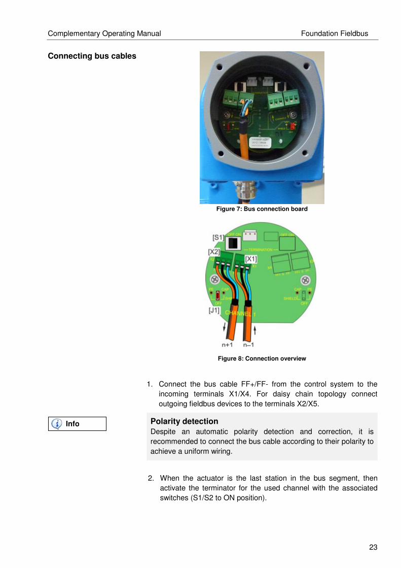
Connecting bus cables
Figure 7: Bus connection board
Figure 8: Connection overview
1. Connect the bus cable FF+/FF- from the control system to the
incoming terminals X1/X4. For daisy chain topology connect
outgoing fieldbus devices to the terminals X2/X5.
Polarity detection
Despite an automatic polarity detection and correction, it is
recommended to connect the bus cable according to their polarity to
achieve a uniform wiring.
2. When the actuator is the last station in the bus segment, then
activate the terminator for the used channel with the associated
switches (S1/S2 to ON position).
Info
Foundation Fieldbus Complementary Operating Manual
24
Terminator
If the terminator is activated, the channel to the next outgoing
fieldbus device is interrupted.
3. When the cable comes from control system it must be connected
on the SHIELD1/2_IN of the screw terminals X1/X4. For daisy
chain topology connect the shields of outgoing cable to the
according terminals X2/X5.
Cable shield
The cable shield is depending on the jumper position J1/J2
connected with the protective conductor or housing or not
connected:
OFF Not connected with housing or protective conductor
PE Connected via bores with housing
CAP Capacitive connected via bores with housing
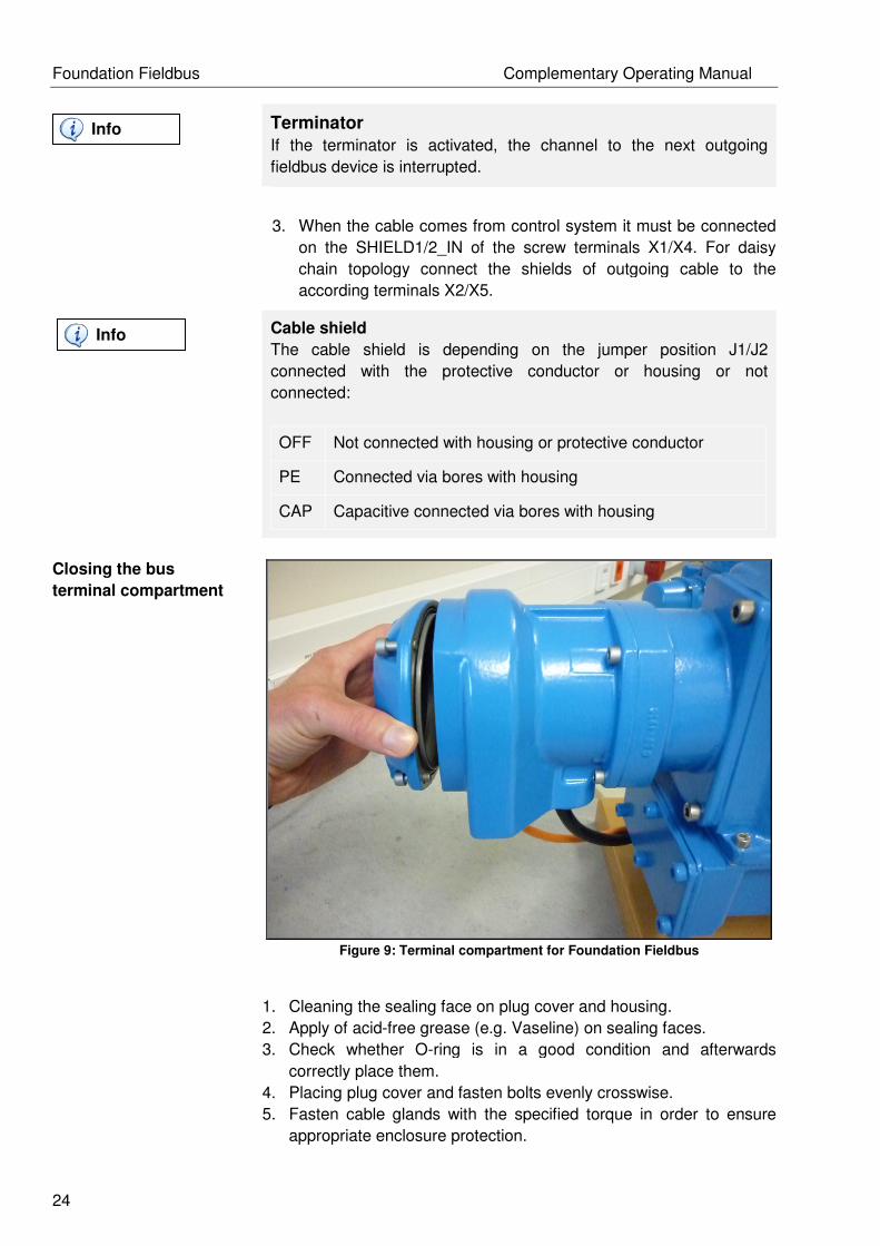
Closing the bus
terminal compartment
Figure 9: Terminal compartment for Foundation Fieldbus
1. Cleaning the sealing face on plug cover and housing.
2. Apply of acid-free grease (e.g. Vaseline) on sealing faces.
3. Check whether O-ring is in a good condition and afterwards
correctly place them.
4. Placing plug cover and fasten bolts evenly crosswise.
5. Fasten cable glands with the specified torque in order to ensure
appropriate enclosure protection.
Info
Info
Complementary Operating Manual Foundation Fieldbus
25
4 Commissioning
4.1 Introduction
Summary of the following chapters
Commissioning software
For demonstrating of commissioning we use tools from National
Instruments in this manual. When other tools or control systems are
used, please read the operating manual before start with
commissioning.
4.2 Installation of Device Description
Device Description
A Device Description (DD) is a collection of files. They allow the
interoperability of the i-matic actuator in Foundation Fieldbus control
systems. An i-matic actuator supports the Device Description version 4
and 5 (short DD4 and DD5). Due to older versions of control systems,
will be offered two versions of the Device Description.
DD - Files
The naming conventions are chosen so, that the filenames consist of
two hex values. The first hex value describes the device revision of the
i-matic actuator and the second one is the DD-revision. For example
the name: 0102.xxx means, that the DD is compatible to first device
revision of the i-matic and the number two is the actual develop
revision of the DD.
For example a DD4 with the name 0101 includes the following files:
0101.ffo Binary files of Device Description.
0101.sym Symbolic text file contains FF records and addresses.
Analog a DD5 consists of these files:
0101.ff5 Binary files of Device Description.
0101.sy5 Symbolic text file contains FF records and addresses.
Common to both DD versions consist this CCF file.
010101.cff Common File Format contains DD-manufacturer and
description of function blocks
Info
Foundation Fieldbus Complementary Operating Manual
26
DD - compatibility
The COMPATIBILITY_REV parameter indicates which DD device
revision is compatible with the DD.
DD - Installation
For install the DD/CFF use the NI-FBUS Interface Configuration Utility.
Installation example
The installation refers to the NI-Configurator from National
Instruments.
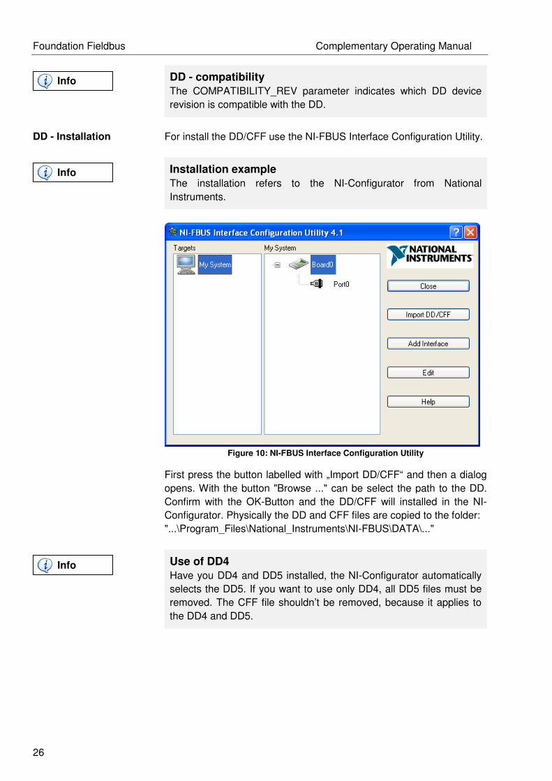
Figure 10: NI-FBUS Interface Configuration Utility
First press the button labelled with „Import DD/CFF“ and then a dialog
opens. With the button "Browse ..." can be select the path to the DD.
Confirm with the OK-Button and the DD/CFF will installed in the NI-
Configurator. Physically the DD and CFF files are copied to the folder:
"...\Program_Files\National_Instruments\NI-FBUS\DATA\..."
Use of DD4
Have you DD4 and DD5 installed, the NI-Configurator automatically
selects the DD5. If you want to use only DD4, all DD5 files must be
removed. The CFF file shouldn’t be removed, because it applies to
the DD4 and DD5.
Info
Info
Info
Complementary Operating Manual Foundation Fieldbus
27
4.3 Network configuration
4.3.1 PD Tag and Node Address
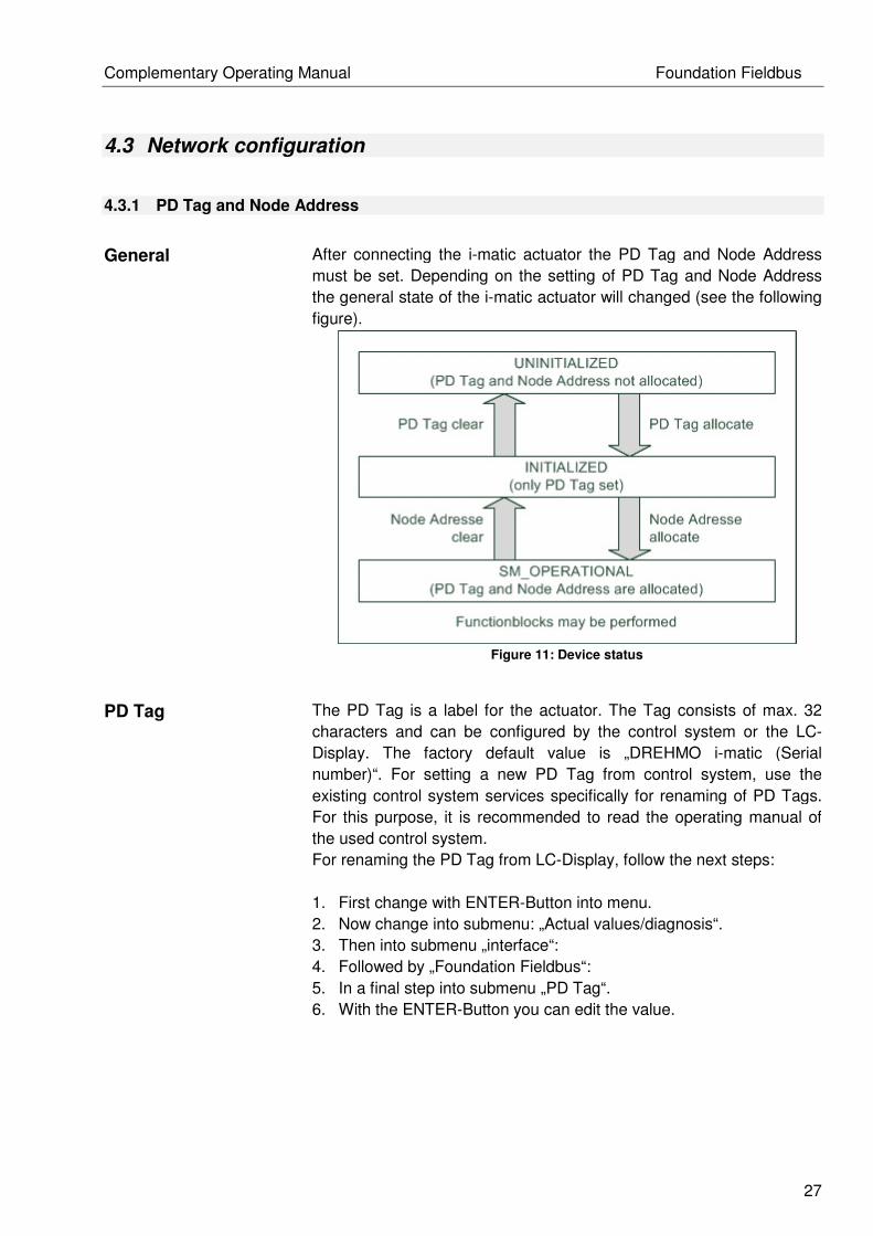
General
After connecting the i-matic actuator the PD Tag and Node Address
must be set. Depending on the setting of PD Tag and Node Address
the general state of the i-matic actuator will changed (see the following
figure).
Figure 11: Device status
PD Tag
The PD Tag is a label for the actuator. The Tag consists of max. 32
characters and can be configured by the control system or the LC-
Display. The factory default value is „DREHMO i-matic (Serial
number)“. For setting a new PD Tag from control system, use the
existing control system services specifically for renaming of PD Tags.
For this purpose, it is recommended to read the operating manual of
the used control system.
For renaming the PD Tag from LC-Display, follow the next steps:
1. First change with ENTER-Button into menu.
2. Now change into submenu: „Actual values/diagnosis“.
3. Then into submenu „interface“:
4. Followed by „Foundation Fieldbus“:
5. In a final step into submenu „PD Tag“.
6. With the ENTER-Button you can edit the value.

Foundation Fieldbus Complementary Operating Manual
28
Operating mode correct?
If the operating mode REMOTE is active, then it isn’t possible to
change the parameter value (PD Tag). Therefore, it will be offered to
change the operating mode into OFF. After changing this parameter
the operating mode is setting back to REMOTE to operate the
actuator from control system.
7. The buttons UP-/DOWN modify the characters, the buttons
LEFT-/RIGHT select the characters.
8. The new value is saved, when has arrived on the last
character (far right) and then press the RIGHT-button.
Node Address
The Node Address is used to address packages in the Foundation
Fieldbus. Each device in the bus is assigned with a unique address.
The valid address values are between 16 - 247 (0x10hex - 0xF7hex).
The factory default value for the Node Address is 25 (0x19hex).
Same device addresses in network
Are two i-matic actuators with the same addresses in the same
Fieldbus Foundation network, keeps one actuator the assigned
address and the other changes it to the default address (from 248 –
251 [0xF8hex - 0xFBhex] ). Due to the globally unique Device ID, the
actuator can be addressed.
Depending on the device type Basic Device or Link Master are own
address ranges defined. Thus, the low addresses are reserved for Link
Master and the high addresses for Basic Devices.
Link Master functionality
The Link Master device with the lowest address takes the LAS
function.
To specify the address ranges, set the parameters V(FUN) for "First
unpolled Node" and V(NUN) for "Number of unpolled Nodes". V(FUN) - 1
defines the highest Link Master Address. V(NUN) defines a range, which
won’t polled from Link Master. V(FUN) + V(NUN) defines the lowest
Basic Device address (see the following figure).
Info
Info
Info

Complementary Operating Manual Foundation Fieldbus
29
Figure 12: Device address range
The Node Address can be changed in two ways similar as the PD Tag.
On the one hand with appropriate control system services. For this it is
recommended to read the operating manual of the control system.
On the other hand via LC-Display:
1. First change with ENTER-Button into menu.
2. Now change into submenu: „Actual values/diagnosis“.
3. Then into submenu „interface“:
4. Followed by „Foundation Fieldbus“:
5. In a final step into submenu „ NodeAddress“.
6. With the ENTER-Button you can edit the value.
Operating mode correct?
If the operating mode REMOTE is active, then it isn’t possible to
change the parameter value (Node Address). Therefore, it will be
offered to change the operating mode into OFF. After changing this
parameter the operating mode is setting back to REMOTE to operate
the actuator from control system.
7. The buttons UP-/DOWN modify the address.
8. The new value is saved, when the ENTER-button is
pressed.
Info

Foundation Fieldbus Complementary Operating Manual
30
4.4 Functionblocks
List of all Function- (FB) and Transducerblocks (TB).
FB / TB FB Name Description
RB Resource Block FB Consist all parameters from Electronic
Nameplate of the i-matic
Positioner_TB Positioner TB Drive the actuator
DigitalIn_TB Digital Input TB Hardwareinterface for digital Inputs of the i-matic
(only for diagnostics)
DigitalOut_TB Digital Output TB Hardwareinterface for digital Outputs of the i-
matic (only for diagnostics)
AnalogIn_TB Analog Input TB Hardwareinterface for analogue Inputs of the i-
matic (only for diagnostics)
AnalogOut_TB Analog Output TB Hardwareinterface for analogue Outputs of the i-
matic (only for diagnostics)
Commiss_TB Commissioning TB Consist all parameters from Parameter of the i-
matic
Diag_TB Diagnostic TB Consist all parameters from Actual
values/Diagnosis and Oper. data acquisition
of the i-matic
DO_1 …
DO_8
Digital Output FB Digital Inputs of the i-matic
DI_1 … DI_10 Digital Input FB Digital Outputs of the i-matic
AO_1 … AO_2 Analog Output FB Analog Inputs of the i-matic
AI_1 … AI_4 Analog Input FB Analog Outputs of the i-matic
SC_1 Signal Characteriser (SGCR) Config Intermediate positions
IS_1 Input Selector (ISEL) With Input Selector you can choose one Output
of several Input channel. (Function of
multiplexor)
PID_1 Proportional Integral
Derivative (PID)
Process controller of the i-matic
Table 5: Functionblocks of i-matic

Complementary Operating Manual Foundation Fieldbus
31
4.4.1 Operating Commands
With the analogue Outputs of the i-matic (AO-FB) it is possible to set the setpoint. The AO-FB
accepted values between 0-100% (0% = valve closed, 100% = valve open).
With the digital Outputs of the i-matic (DO-FB) it is possible to set the commands for
OPEN/STOP/CLOSE. The DO-FB accepted the values 0 for OPEN, 1 for CLOSE and 2 for STOP.
4.4.2 Feedback
The analogue feedback values of the actuator you will get from Analogue Input (AI-FB). The same is
valid for the digital feedback values from the Digital Inputs (DI-FB).
Foundation Fieldbus Complementary Operating Manual
32
5 Additional Functions
Additional functions of the Foundation Fieldbus Interface.
5.1 Data Channel
With the Data Channel any parameter and data will be send from control system to the actuator.
5.2 Simulation
With Simulation the Function blocks could be simulated without moving the actuator. This function is
useful for commissioning.
5.3 Redundancy
One version of the Foundation Fieldbus Interface is available for Redundancy concept and consists
of two Fieldbus Kits (FBK2’s) from Softing.
5.4 Firmware Update
The Firmware Update of the Foundation Fieldbus Interface and the FBK’s could be done as usual
with i-matic Explorer 2 (you find it on our Website).

Complementary Operating Manual Foundation Fieldbus
33
6 Application Examples
6.1 General Information
Control system for the application examples
All examples are shown with tools from National Instruments. If you
use other tools or control systems, please read the operating manual
of the control system before you start commissioning.
6.1.1 Reset
Precondition
To control the actuator over Foundation Fieldbus it is recommended
to delete the Blockmodel previously. For this set the RESTART
parameter with value “Defaults”.
Figure 13: Reset of FBAP
Info
Info

Foundation Fieldbus Complementary Operating Manual
34
6.1.2 Download of the Function block application
Download
For execute and request the functions blocks by the LAS, transmit
the function block application to the actuator. For this purpose run
the dialog "Download Project ..." (see following Figure).
Figure 14: Download the function block application
In the dialog box „Download Configuration” the following options:
• Clear Devices,
• Automatic Mode Handling
are to activate and then start download by press the appropriate
button.
Figure 15: Download Configuration dialog
Info

Complementary Operating Manual Foundation Fieldbus
35
6.2 Drive the actuator for tests purposes
Application
description
The following example demonstrates to drive an i-matic actuator for
test purposes by discrete and analogue commands without building a
block model.
Precondition
For controlling the actuator via Foundation Fieldbus it is
recommended to delete the previously used block model. For this
purpose set the parameter RESTART from Resource Block (RB) to
the value “Defaults” (see chapter 6.1.1 Reset).
Usage of
Positioner_TB
For controlling the actuator’s for test purposes without building a block
model or executing a block model download use the Postioner_TB.
Set Automatic Bit
If you drive the actuator with setpoint, the AUTO Bit must be set to
activate the position controller. For this the parameter
PRM_DCS_CTRL_AUTO_BIT is set to „Force enabled“ in
Commiss_TB. For controlling with discrete commands the parameter
is set back to the value „acc. REMOTE“.
Drive the
i-matic actuator with
discrete commands
To drive the actuator with discrete commands from Positioner_TB set
the ACTUAL of MODE_BLK parameter to value MAN. For this set
Target to value MAN. After a short time the ACTUAL of the
MODE_BLK parameter gets the value MAN. Additionally the parameter
ACTIVE_CHANNEL gets the value „Channel setpoint_commands not
active (MAN)”. If you set the FINAL_VALUE_COMMANDS, the
actuator drives in OPEN or CLOSE direction or stops with STOP
command. In addition the STATUS of FINAL_VALUE_COMMANDS is
set to Good_Cascade or Good_NonCascade and the STATUS of
FINAL_VALUE_SETPOINT is set to value BAD.
FINAL_VALUE_COMMAND Description
0x00 CLOSE
0x01 OPEN
0x02 STOP
Table 6: Controls for discrete commands
Info
Info

Foundation Fieldbus Complementary Operating Manual
36
With the parameter PRIMARY_VALUE_ACTUAL_POSITION it is
possible to read the actual position of the actuator. The following figure
shows the Positioner_TB with his parameters.
Figure 16: Positioner_TB with parameters
Drive the
i-matic actuator with
analog commands
To drive the actuator with analogue commands from Positioner_TB set
the ACTUAL of MODE_BLK parameter to value MAN. For this set
Target to value MAN. After a short time the ACTUAL of the
MODE_BLK parameter gets the value MAN. Additionally the parameter
ACTIVE_CHANNEL gets the value „Channel setpoint active (MAN)”. If
you set the FINAL_VALUE_SETPOINT, the actuator controls the
actual position to the setpoint position. In addition the STATUS of
FINAL_VALUE_SETPOINT is set to Good_Cascade or
Good_NonCascade and the STATUS of FINAL_VALUE_COMMANDS
is set to value BAD.

Complementary Operating Manual Foundation Fieldbus
37
FINAL_VALUE_SETPOINT Description
0 - 100 Setpoint of the actuator
Table 7: Setpoint for analog control
If the actuator doesn’t drive
Check the parameter XD_ERROR and XD_ERREXT of the
Positioner_TB. Normally the values are 0x00.
Info

Foundation Fieldbus Complementary Operating Manual
38
6.3 Control via discrete commands (single bit)
Application
description
The following example demonstrates how to move the i-matic actuator
with the discrete commands OPEN, CLOSE and STOP via Foundation
Fieldbus.
Precondition
For controlling the actuator via Foundation Fieldbus it is
recommended to delete the previously used block model. For this
purpose set the parameter RESTART from Resource Block (RB) to
the value “Defaults” (see chapter 6.1.1 Reset).
Reset Automatic Bit
If you drive the actuator with discrete commands it must be
configured accordingly. In Commiss_TB the parameter
PRM_DCS_CTRL_AUTO_BIT is set to value „acc. REMOTE“ or
„Force disabled“.
Design a
block model
First, design a block model. For the implementation use three Discrete
Output (DO) function blocks (see following Figure). One function block
for the signal OPEN, a second for the signal CLOSE and a third for the
signal STOP.
Figure 17: Representation of three DO function blocks
Info
Info

Complementary Operating Manual Foundation Fieldbus
39
Prior configuration the block status of each function blocks is set to
OOS (Out Of Service). For this purpose the TARGET of the parameter
MODE_BLK is set to OOS (see following Figure).
Figure 18: Changing block status
Writing commands/parameters
All commands or modified parameters in NI-Configurator are always
transmitted to the device, when pressing the button "Write Changes".
If the changes were accepted by the device, the yellow background
and the star before the parameter disappear. Read all parameters
from the device by clicking the "Read All" button.
After a short time the Actual of parameter MODE_BLK should change
to OOS. Then the function block is in OOS state. Subsequently the
channels from each functional block to DigitalOut Transducer Block
(DOTB) are setting. The following table shows an exemplary
assignment of the channels of the functional blocks.
Block Channel Description
DO1 Ch fieldbus OPEN Signal OPEN
DO2 Ch fieldbus CLOSE Signal CLOSE
DO3 Ch fieldbus STOP Signal STOP
Table 8: Assignment of channels from all DO FB
Info
Foundation Fieldbus Complementary Operating Manual
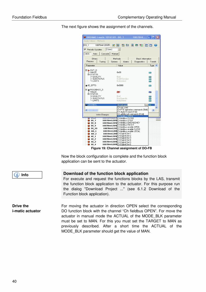
40
The next figure shows the assignment of the channels.
Figure 19: Channel assignment of DO-FB
Now the block configuration is complete and the function block
application can be sent to the actuator.
Download of the function block application
For execute and request the functions blocks by the LAS, transmit
the function block application to the actuator. For this purpose run
the dialog "Download Project ..." (see 6.1.2 Download of the
Function block application).
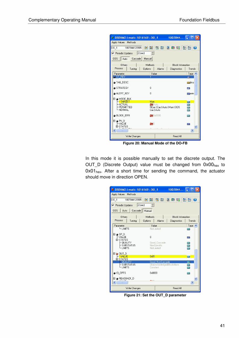
Drive the
i-matic actuator
For moving the actuator in direction OPEN select the corresponding
DO function block with the channel “Ch fieldbus OPEN”. For move the
actuator in manual mode the ACTUAL of the MODE_BLK parameter
must be set to MAN. For this you must set the TARGET to MAN as
previously described. After a short time the ACTUAL of the
MODE_BLK parameter should get the value of MAN.
Info
Complementary Operating Manual Foundation Fieldbus
41
Figure 20: Manual Mode of the DO-FB
In this mode it is possible manually to set the discrete output. The
OUT_D (Discrete Output) value must be changed from 0x00hex to
0x01hex. After a short time for sending the command, the actuator
should move in direction OPEN.
Figure 21: Set the OUT_D parameter

Foundation Fieldbus Complementary Operating Manual
42
Valid values for the OUT_D parameters are:
OUT_D Value Description
0x00hex Reset output
0x01hex Set output
Table 9: Description of the valid OUT_D values
This procedure of set / reset of the outputs is applies analogue to the
other discrete functional blocks (DO). The actual position can be read
in parameter PRIMARY_VALUE_ACTUAL_POSITION from the
Positioner_TB.
Figure 22: Actual position value of the actuator
The percentage values have the following meanings:
Actuator pos. Description
0 Actuator fully closed
1-99 Percentage indication of the open actuator
100 Actuator fully opened
Table 10: Values definition the drive position
Complementary Operating Manual Foundation Fieldbus
43
If the actuator doesn’t move
If this case occurs then it will have different causes, on the one hand
the actuator is already fully opened and it can’t be moved in the
OPEN direction. For CLOSE direction it applies analogue. On the
other hand, when the STOP signal is set the actuator can’t be
moved. The STOP signal has always a higher priority than the
OPEN or CLOSE commands.
Another possible cause could be, if before the actuator is moved in
OPEN direction and the output of the DO function block isn’t reset,
then it isn’t possible to move the actuator in the CLOSE direction
with the other DO function block.
Another possible cause is an error in the configuration of the DO-FB,
when the parameter BLOCK_ERR_DESC_1 signals an error. It
could be corrected if the block will be reconfigured.
A final cause of the error could be that the actuator is not switched to
the mode REMOTE. It signals when the parameter XD_ERROR in
Positioner_TB has the value “General Error” and the XD_ERREXT
has the value “Not ready indication”. To solve this change the mode
in REMOTE on HMI of the actuator.
Info

Foundation Fieldbus Complementary Operating Manual
44
6.4 Control via discrete commands (multi bit)
Application
description
The following example demonstrates how to move the i-matic actuator
with the discrete commands OPEN, CLOSE and STOP in one FB via
Foundation Fieldbus.
Precondition
For controlling the actuator via Foundation Fieldbus it is
recommended to delete the previously used block model. For this
purpose set the parameter RESTART from Resource Block (RB) to
the value “Defaults” (see chapter 6.1.1 Reset).
Reset Automatic Bit
If you drive the actuator with discrete commands it must be
configured accordingly. In Commiss_TB the parameter
PRM_DCS_CTRL_AUTO_BIT is set to value „acc. REMOTE“ or
„Force disabled“.
Design a
block model
First, design a block model. For the implementation use one Discrete
Output (DO) function block (see following Figure). This block control
the signal OPEN, CLOSE and STOP.
Figure 23: Representation of one DO-FB
Info
Info
Complementary Operating Manual Foundation Fieldbus
45
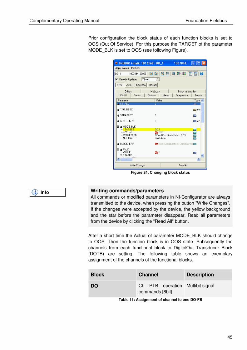
Prior configuration the block status of each function blocks is set to
OOS (Out Of Service). For this purpose the TARGET of the parameter
MODE_BLK is set to OOS (see following Figure).
Figure 24: Changing block status
Writing commands/parameters
All commands or modified parameters in NI-Configurator are always
transmitted to the device, when pressing the button "Write Changes".
If the changes were accepted by the device, the yellow background
and the star before the parameter disappear. Read all parameters
from the device by clicking the "Read All" button.
After a short time the Actual of parameter MODE_BLK should change
to OOS. Then the function block is in OOS state. Subsequently the
channels from each functional block to DigitalOut Transducer Block
(DOTB) are setting. The following table shows an exemplary
assignment of the channels of the functional blocks.
Block Channel Description
DO Ch PTB operation
commands [8bit]
Multibit signal
Table 11: Assignment of channel to one DO-FB
Info

Foundation Fieldbus Complementary Operating Manual
46
The next figure shows the assignment of the channels.
Figure 25: Channel assignment of DO-FB
Now the block configuration is complete and the function block
application can be sent to the actuator.
Download of the function block application
For execute and request the functions blocks by the LAS, transmit
the function block application to the actuator. For this purpose run
the dialog "Download Project ..." (see 6.1.2 Download of the
Function block application).
Drive the
i-matic actuator
For moving the actuator in direction OPEN select the DO function
block. For move the actuator in manual mode the ACTUAL of the
MODE_BLK parameter must be set to MAN. For this you must set the
TARGET to MAN as described previously. After a short time the
ACTUAL of the MODE_BLK parameter should get the value of MAN.
Info

Complementary Operating Manual Foundation Fieldbus
47
Figure 26: Manual Mode of the DO-FB
In this mode it is possible manually to set the discrete output. The
OUT_D (Discrete Output) value is default 0x02hex for STOP the
actuator. If it chooses the value 0x00hex for CLOSE the actuator drives
in close direction. If the value changed to value 0x01hex for OPEN the
actuator drives in open direction.
Figure 27: Set the OUT_D parameter

Foundation Fieldbus Complementary Operating Manual
48
Valid values for the OUT_D parameters are:
OUT_D Value Description
0x00hex Signal CLOSE
0x01hex Signal OPEN
0x02hex Signal STOP
Table 12: Description of the valid OUT_D values
The actual position can be read in parameter
PRIMARY_VALUE_ACTUAL_POSITION from the Positioner_TB.
Figure 28: Actual position value of the actuator
The percentage values have the following meanings:
Actuator pos. Description
0 Actuator fully closed
1-99 Percentage indication of the open actuator
100 Actuator fully opened
Table 13: Values definition the drive position

Complementary Operating Manual Foundation Fieldbus
49
If the actuator doesn’t move
If this case occurs then it will have different causes, on the one hand
the actuator is already fully opened and it can’t be moved in the
OPEN direction. For CLOSE direction it applies analogue. On the
other hand, when the STOP signal is set the actuator can’t be
moved. The STOP signal has always a higher priority than the
OPEN or CLOSE commands.
Another possible cause could be, if before the actuator is moved in
OPEN direction and the output of the DO function block isn’t reset,
then it isn’t possible to move the actuator in the CLOSE direction
with the other DO function block.
Another possible cause is an error in the configuration of the DO-FB,
when the parameter BLOCK_ERR_DESC_1 signals an error. It
could be corrected if the block will be reconfigured.
A final cause of the error could be that the actuator is not switched to
the mode REMOTE. It signals when the parameter XD_ERROR in
Positioner_TB has the value “General Error” and the XD_ERREXT
has the value “Not ready indication”. To solve this change the mode
in REMOTE on HMI of the actuator.
Info

Foundation Fieldbus Complementary Operating Manual
50
6.5 Control via analog setpoint (without Automatic-Bit)
Application
description
The following example demonstrates how to move the i-matic actuator
with the analogue command setpoint via Foundation Fieldbus. The
Automatic-Bit is preconfigured in the actuator.
Precondition
For controlling the actuator via Foundation Fieldbus it is
recommended to delete the previously used block model. For this
purpose set the parameter RESTART from Resource Block (RB) to
the value “Defaults” (see chapter 6.1.1 Reset).
Set Automatic Bit
If you drive the actuator with analogue commands it must be
configured accordingly. In Commiss_TB the parameter
PRM_DCS_CTRL_AUTO_BIT is set to value „Force enabled“.
Design a
block model
First, design a block model. For the implementation use only the
Function Block Analog Output (see following Figure). The Function
Block is linked with the appropriate channel.
Figure 29: Representation of the AO-FB
Info
Info
Complementary Operating Manual Foundation Fieldbus
51
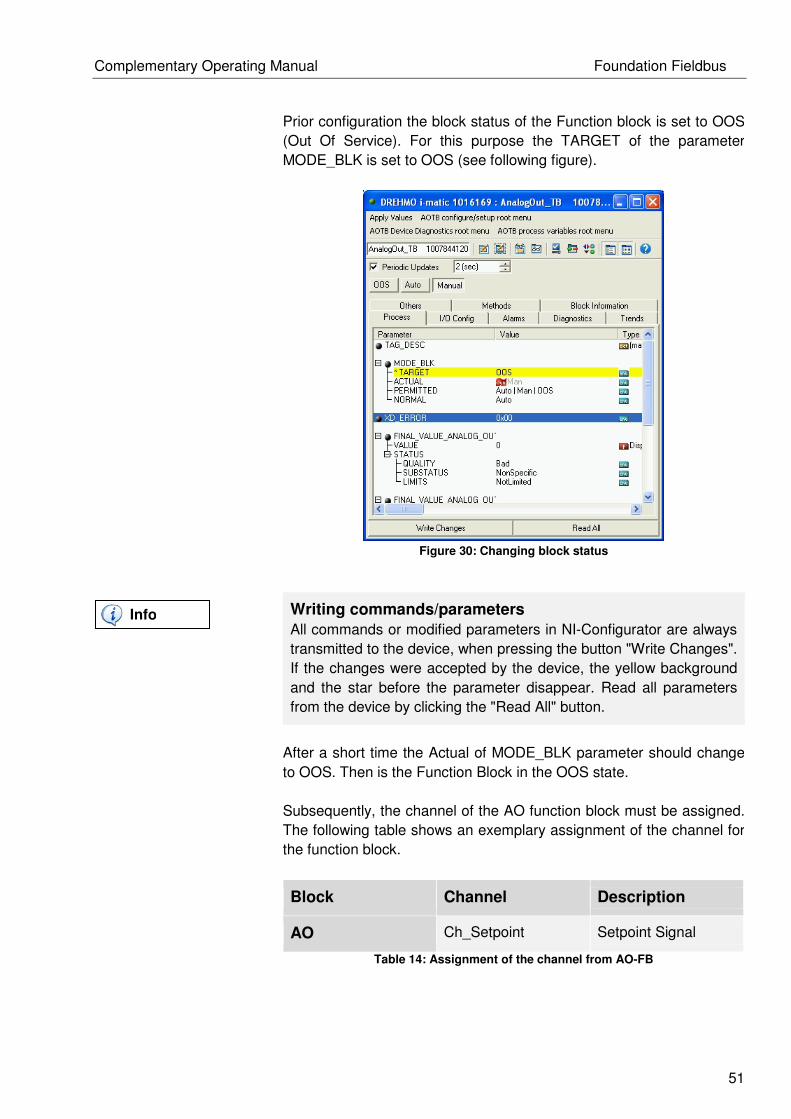
Prior configuration the block status of the Function block is set to OOS
(Out Of Service). For this purpose the TARGET of the parameter
MODE_BLK is set to OOS (see following figure).
Figure 30: Changing block status
Writing commands/parameters
All commands or modified parameters in NI-Configurator are always
transmitted to the device, when pressing the button "Write Changes".
If the changes were accepted by the device, the yellow background
and the star before the parameter disappear. Read all parameters
from the device by clicking the "Read All" button.
After a short time the Actual of MODE_BLK parameter should change
to OOS. Then is the Function Block in the OOS state.
Subsequently, the channel of the AO function block must be assigned.
The following table shows an exemplary assignment of the channel for
the function block.
Block Channel Description
AO Ch_Setpoint Setpoint Signal
Table 14: Assignment of the channel from AO-FB
Info

Foundation Fieldbus Complementary Operating Manual
52
Figure 31: Channel assignment of AO-FB
Alternative channel assignment
The configuration of the channels can be performed via Foundation
Fieldbus methods.
Now the block configuration is complete and the Function Block
Application can be sent to the actuator.
Download of the function block application
For execute and request the functions blocks by the LAS, transmit
the function block application to the actuator. For this purpose run
the dialog "Download Project ..." (see 6.1.2 Download of the
Function block application).
Info
Info
Complementary Operating Manual Foundation Fieldbus
53
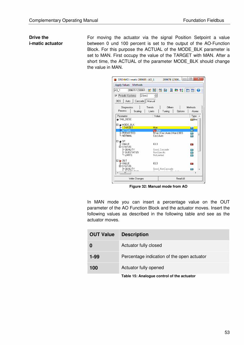
Drive the
i-matic actuator
For moving the actuator via the signal Position Setpoint a value
between 0 und 100 percent is set to the output of the AO-Function
Block. For this purpose the ACTUAL of the MODE_BLK parameter is
set to MAN. First occupy the value of the TARGET with MAN. After a
short time, the ACTUAL of the parameter MODE_BLK should change
the value in MAN.
Figure 32: Manual mode from AO
In MAN mode you can insert a percentage value on the OUT
parameter of the AO Function Block and the actuator moves. Insert the
following values as described in the following table and see as the
actuator moves.
OUT Value Description
0 Actuator fully closed
1-99 Percentage indication of the open actuator
100 Actuator fully opened
Table 15: Analogue control of the actuator

Foundation Fieldbus Complementary Operating Manual
54
The following figure shows the input of the setpoint on AO-Function
block.
Figure 33: Setpoint input from AO-FB
The actual position can be read in parameter
PRIMARY_VALUE_ACTUAL_POSITION from the Positioner_TB.
Figure 34: Actual position
Complementary Operating Manual Foundation Fieldbus
55
The percentage values have the following meanings:
Actuator pos. Description
0 Actuator fully closed
1-99 Percentage indication of the open actuator
100 Actuator fully opened
Table 16: Value definition of actuator position
If the actuator doesn’t move
If this case occurs then it will have different causes, on the one hand
the actuator is already fully opened and it can’t be moved in the
OPEN direction. For CLOSE direction it applies analogue.
Another possible cause is an error in the configuration of the AO-FB,
when the parameter BLOCK_ERR_DESC_1 signals an error. It
could be corrected if the block will be reconfigured.
A final cause of the error could be that the actuator is not switched to
the mode REMOTE. It signals when the parameter XD_ERROR in
Positioner_TB has the value “General Error” and the XD_ERREXT
has the value “Not ready indication”. To solve this change the mode
in REMOTE on HMI of the actuator.
Info

Foundation Fieldbus Complementary Operating Manual
56
6.6 Control via analog setpoint (with Automatic-Bit)
Application
description
The following example demonstrates how to move the i-matic actuator
with the analogue command setpoint via Foundation Fieldbus. The
automatic-Bit will be set by a DO-Function block.
Precondition
For controlling the actuator via Foundation Fieldbus it is recommend
to delete the previously used block model. For this purpose set the
parameter RESTART from Resource Block (RB) to the value
“Defaults” (see chapter 6.1.1 Reset).
Deactivate the Automatic Bit
In this case the parameter PRM_DCS_CTRL_AUTO_BIT in
Commiss_TB should set to value „Force disabled“.
Design a
block model
First, design a block model. For the implementation use the Transducer
Blocks AnalogOut_TB, DigitalOut_TB and the Function Blocks Analog
Output (AO) and Discrete Output (DO) (see following figure). A
configurable output from the AnalogOut_TB is set to Position Setpoint.
From DigitalOut_TB is a configurable output set to the Signal
AUTOMATIC. Subsequently the Function Blocks are linked with the
appropriate channel.
Figure 35: Representation of AOTB, DOTB, AO and DO
Info
Info
Complementary Operating Manual Foundation Fieldbus
57
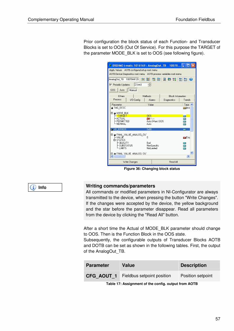
Prior configuration the block status of each Function- and Transducer
Blocks is set to OOS (Out Of Service). For this purpose the TARGET of
the parameter MODE_BLK is set to OOS (see following figure).
Figure 36: Changing block status
Writing commands/parameters
All commands or modified parameters in NI-Configurator are always
transmitted to the device, when pressing the button "Write Changes".
If the changes were accepted by the device, the yellow background
and the star before the parameter disappear. Read all parameters
from the device by clicking the "Read All" button.
After a short time the Actual of MODE_BLK parameter should change
to OOS. Then is the Function Block in the OOS state.
Subsequently, the configurable outputs of Transducer Blocks AOTB
and DOTB can be set as shown in the following tables. First, the output
of the AnalogOut_TB.
Parameter Value Description
CFG_AOUT_1 Fieldbus setpoint position Position setpoint
Table 17: Assignment of the config. output from AOTB
Info

Foundation Fieldbus Complementary Operating Manual
58
The following figure shows the assignment of the channels “Fieldbus
setpoint position” of the AOTB.
Figure 37: Assignment of the config. output from AOTB
Followed by the configurable output of the DigitalOut_TB.
Parameter Value Description
CFG_DOUT_1 Fieldbus SETPOINT Signal AUTOMATIC
Table 18: Assignment of the config. output from DOTB
Figure 38: Assignment of the config. output from DOTB

Complementary Operating Manual Foundation Fieldbus
59
After the Transducer Blocks are assigned with the correct signals, the
corresponding channel can be configured to the Function Blocks. The
first example is shown at the AO Function Block. Based on selecting
the configurable output CFG_AOUT_1 of AnalogOut_TB is the
associated channel "Ch AnalogOut1" in the AO Function Block to
select. The following figure shows the selection of the channel.
Figure 39: Channel assignment of the AO-FB
Now the block configuration is completed and the Function Block
Application can be downloaded to the actuator.
Alternative channel assignment
The configuration of the channels can be performed via Foundation
Fieldbus methods.
Info

Foundation Fieldbus Complementary Operating Manual
60
For the DO Function Block select the corresponding channel "Ch
DigitalOut 1”. This is the associated channel for the configurable output
CFG_DOUT_1 of the DigitalOut_TB.
Figure 40: Channel assignment of the DO-FB
Now the block configuration is complete and the Function Block
Application can be sent to the actuator.
Download of the function block application
For execute and request the functions blocks by the LAS, transmit
the function block application to the actuator. For this purpose run
the dialog "Download Project ..." (see 6.1.2 Download of the
Function block application).
Drive the
i-matic actuator
For moving the actuator via the signal Position Setpoint is set the
signal AUTOMATIC in the DO Function Block before. Subsequently the
actuator can be moved via any percentage value on the output of the
AO Function Block. When you want to configure both Function Blocks,
they must be set into the block mode MAN. For this purpose the
ACTUAL of the MODE_BLK parameter is set to MAN. As described
above, the value of the TARGET is occupied with MAN. After a short
time, the ACTUAL of the parameter MODE_BLK should change the
value in MAN. This process is to repeat for the AO- and DO- Function
Block.
Info

Complementary Operating Manual Foundation Fieldbus
61
Figure 41: Manual mode of the DO
First activate the signal AUTOMATIC. For this purpose set the
parameter OUT_D from 0x00hex to the value 0x01hex.
Figure 42: Set signal AUTOMATIC

Foundation Fieldbus Complementary Operating Manual
62
After activated the signal AUTOMATIC, it is possible to move the
actuator with an analogue position value. For this you can insert a
percentage value on the OUT parameter of the AO Function Block and
the actuator moves. Insert the following values as described in the
following table and see as the actuator moves.
OUT Value Description
0 Actuator fully closed
1-99 Percentage indication of the open actuator
100 Actuator fully opened
Table 19: Analog control of the actuator
The following figure shows as the actuator moves to 50% of the length
of the path.
Figure 43: analogue control of the position setpoint
During the drive of the i-matic actuator the actual position can be read
in parameter PRIMARY_VALUE_ACTUAL_POSITION from the
Positioner_TB.
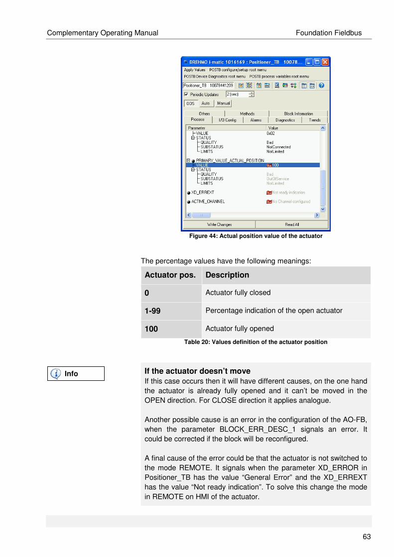
Complementary Operating Manual Foundation Fieldbus
63
Figure 44: Actual position value of the actuator
The percentage values have the following meanings:
Actuator pos. Description
0 Actuator fully closed
1-99 Percentage indication of the open actuator
100 Actuator fully opened
Table 20: Values definition of the actuator position
If the actuator doesn’t move
If this case occurs then it will have different causes, on the one hand
the actuator is already fully opened and it can’t be moved in the
OPEN direction. For CLOSE direction it applies analogue.
Another possible cause is an error in the configuration of the AO-FB,
when the parameter BLOCK_ERR_DESC_1 signals an error. It
could be corrected if the block will be reconfigured.
A final cause of the error could be that the actuator is not switched to
the mode REMOTE. It signals when the parameter XD_ERROR in
Positioner_TB has the value “General Error” and the XD_ERREXT
has the value “Not ready indication”. To solve this change the mode
in REMOTE on HMI of the actuator.
Info
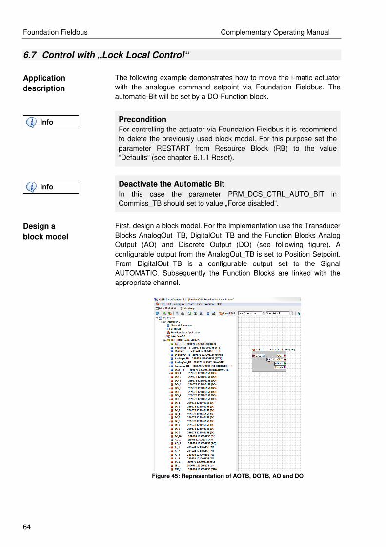
Foundation Fieldbus Complementary Operating Manual
64
6.7 Control with „Lock Local Control“
Application
description
The following example demonstrates how to move the i-matic actuator
with the analogue command setpoint via Foundation Fieldbus. The
automatic-Bit will be set by a DO-Function block.
Precondition
For controlling the actuator via Foundation Fieldbus it is recommend
to delete the previously used block model. For this purpose set the
parameter RESTART from Resource Block (RB) to the value
“Defaults” (see chapter 6.1.1 Reset).
Deactivate the Automatic Bit
In this case the parameter PRM_DCS_CTRL_AUTO_BIT in
Commiss_TB should set to value „Force disabled“.
Design a
block model
First, design a block model. For the implementation use the Transducer
Blocks AnalogOut_TB, DigitalOut_TB and the Function Blocks Analog
Output (AO) and Discrete Output (DO) (see following figure). A
configurable output from the AnalogOut_TB is set to Position Setpoint.
From DigitalOut_TB is a configurable output set to the Signal
AUTOMATIC. Subsequently the Function Blocks are linked with the
appropriate channel.
Figure 45: Representation of AOTB, DOTB, AO and DO
Info
Info

Complementary Operating Manual Foundation Fieldbus
65
Prior configuration the block status of each Function- and Transducer
Blocks is set to OOS (Out Of Service). For this purpose the TARGET of
the parameter MODE_BLK is set to OOS (see following figure).
Figure 46: Changing block status
Writing commands/parameters
All commands or modified parameters in NI-Configurator are always
transmitted to the device, when pressing the button "Write Changes".
If the changes were accepted by the device, the yellow background
and the star before the parameter disappear. Read all parameters
from the device by clicking the "Read All" button.
After a short time the Actual of MODE_BLK parameter should change
to OOS. Then is the Function Block in the OOS state.
Subsequently, the configurable outputs of Transducer Blocks AOTB
and DOTB can be set as shown in the following tables. First, the output
of the AnalogOut_TB.
Parameter Value Description
CFG_AOUT_1 Fieldbus setpoint position Position setpoint
Table 21: Assignment of the config. output from AOTB
Info
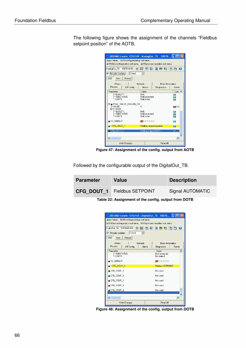
Foundation Fieldbus Complementary Operating Manual
66
The following figure shows the assignment of the channels “Fieldbus
setpoint position” of the AOTB.
Figure 47: Assignment of the config. output from AOTB
Followed by the configurable output of the DigitalOut_TB.
Parameter Value Description
CFG_DOUT_1 Fieldbus SETPOINT Signal AUTOMATIC
Table 22: Assignment of the config. output from DOTB
Figure 48: Assignment of the config. output from DOTB

Complementary Operating Manual Foundation Fieldbus
67
After the Transducer Blocks are assigned with the correct signals, the
corresponding channel can be configured to the Function Blocks. The
first example is shown at the AO Function Block. Based on selecting
the configurable output CFG_AOUT_1 of AnalogOut_TB is the
associated channel "Ch AnalogOut1" in the AO Function Block to
select. The following figure shows the selection of the channel.
Figure 49: Channel assignment of the AO-FB
Now the block configuration is completed and the Function Block
Application can be downloaded to the actuator.
Alternative channel assignment
The configuration of the channels can be performed via Foundation
Fieldbus methods.
Info
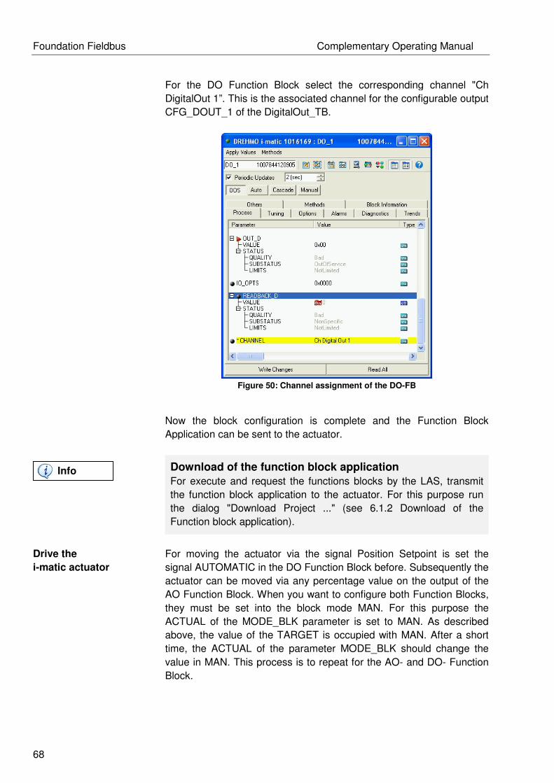
Foundation Fieldbus Complementary Operating Manual
68
For the DO Function Block select the corresponding channel "Ch
DigitalOut 1”. This is the associated channel for the configurable output
CFG_DOUT_1 of the DigitalOut_TB.
Figure 50: Channel assignment of the DO-FB
Now the block configuration is complete and the Function Block
Application can be sent to the actuator.
Download of the function block application
For execute and request the functions blocks by the LAS, transmit
the function block application to the actuator. For this purpose run
the dialog "Download Project ..." (see 6.1.2 Download of the
Function block application).
Drive the
i-matic actuator
For moving the actuator via the signal Position Setpoint is set the
signal AUTOMATIC in the DO Function Block before. Subsequently the
actuator can be moved via any percentage value on the output of the
AO Function Block. When you want to configure both Function Blocks,
they must be set into the block mode MAN. For this purpose the
ACTUAL of the MODE_BLK parameter is set to MAN. As described
above, the value of the TARGET is occupied with MAN. After a short
time, the ACTUAL of the parameter MODE_BLK should change the
value in MAN. This process is to repeat for the AO- and DO- Function
Block.
Info
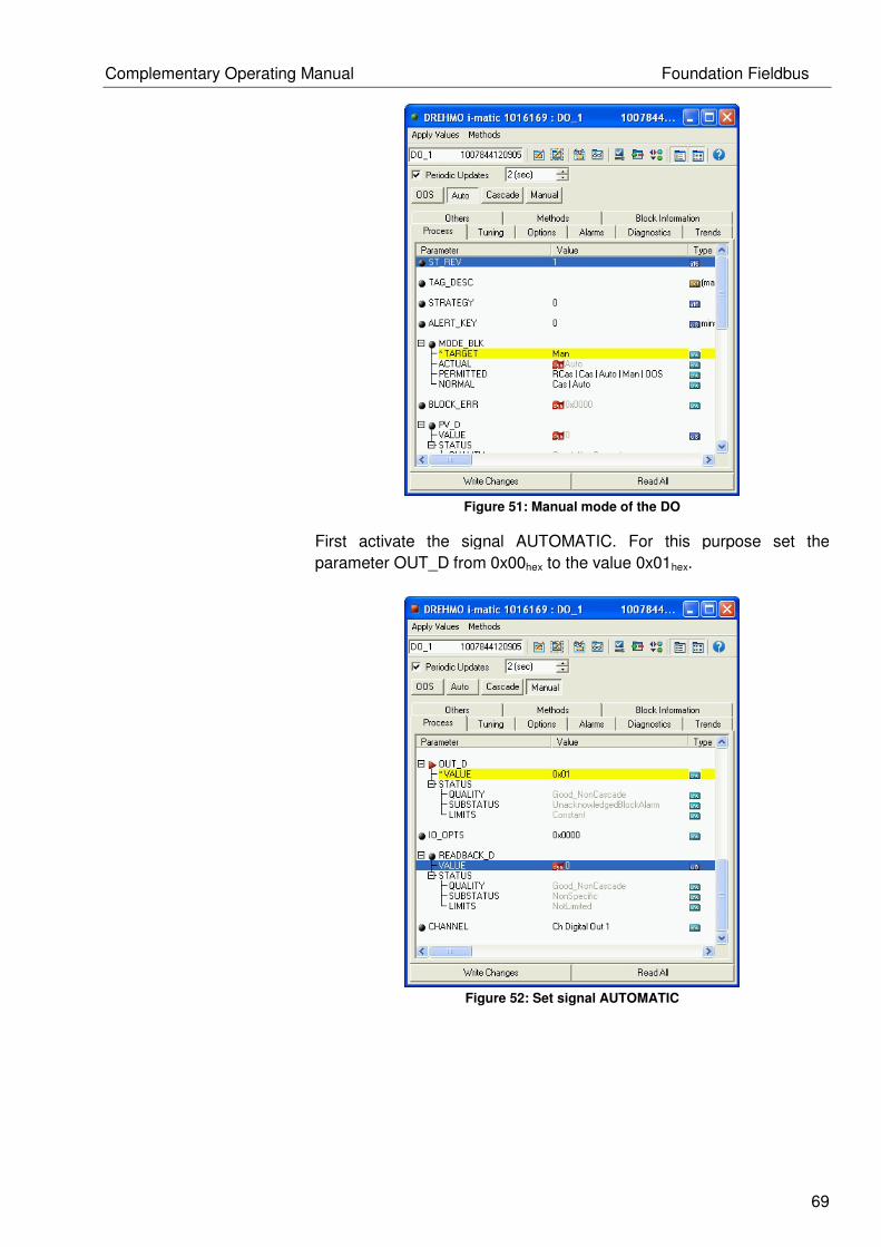
Complementary Operating Manual Foundation Fieldbus
69
Figure 51: Manual mode of the DO
First activate the signal AUTOMATIC. For this purpose set the
parameter OUT_D from 0x00hex to the value 0x01hex.
Figure 52: Set signal AUTOMATIC

Foundation Fieldbus Complementary Operating Manual
70
After activated the signal AUTOMATIC, it is possible to move the
actuator with an analogue position value. For this you can insert a
percentage value on the OUT parameter of the AO Function Block and
the actuator moves. Insert the following values as described in the
following table and see as the actuator moves.
OUT Value Description
0 Actuator fully closed
1-99 Percentage indication of the open actuator
100 Actuator fully opened
Table 23: Analog control of the actuator
The following figure shows as the actuator moves to 50% of the length
of the path.
Figure 53: analogue control of the position setpoint
During the drive of the i-matic actuator the actual position can be read
in parameter PRIMARY_VALUE_ACTUAL_POSITION from the
Positioner_TB.

Complementary Operating Manual Foundation Fieldbus
71
Figure 54: Actual position value of the actuator
The percentage values have the following meanings:
Actuator pos. Description
0 Actuator fully closed
1-99 Percentage indication of the open actuator
100 Actuator fully opened
Table 24: Values definition of the actuator position
If the actuator doesn’t move
If this case occurs then it will have different causes, on the one hand
the actuator is already fully opened and it can’t be moved in the
OPEN direction. For CLOSE direction it applies analogue.
Another possible cause is an error in the configuration of the AO-FB,
when the parameter BLOCK_ERR_DESC_1 signals an error. It
could be corrected if the block will be reconfigured.
A final cause of the error could be that the actuator is not switched to
the mode REMOTE. It signals when the parameter XD_ERROR in
Positioner_TB has the value “General Error” and the XD_ERREXT
has the value “Not ready indication”. To solve this change the mode
in REMOTE on HMI of the actuator.
Info

Foundation Fieldbus Complementary Operating Manual
72
7 Description Foundation Fieldbus-Board
7.1 Notifications (optical signals)
Figure 55: FF - Baugruppe
Name Description
RES LED RESET
DBG LED DEBUG
CAN LED CAN
BA1 LED Active Comm. Channel 1
DX1 LED Data Exchange Channel 1
CH1 LED Channel 1 active
BA2 LED Active Comm. Channel 2
DX2 LED Data Exchange Channel 2
D7 FBK2 from Softing
X4 FF-Bus Channel 1
X6 FF-Bus channel 2
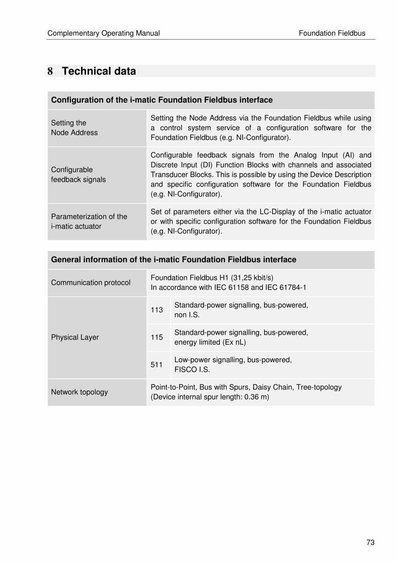
Complementary Operating Manual Foundation Fieldbus
73
8 Technical data
Configuration of the i-matic Foundation Fieldbus interface
Setting the
Node Address
Setting the Node Address via the Foundation Fieldbus while using
a control system service of a configuration software for the
Foundation Fieldbus (e.g. NI-Configurator).
Configurable
feedback signals
Configurable feedback signals from the Analog Input (AI) and
Discrete Input (DI) Function Blocks with channels and associated
Transducer Blocks. This is possible by using the Device Description
and specific configuration software for the Foundation Fieldbus
(e.g. NI-Configurator).
Parameterization of the
i-matic actuator
Set of parameters either via the LC-Display of the i-matic actuator
or with specific configuration software for the Foundation Fieldbus
(e.g. NI-Configurator).
General information of the i-matic Foundation Fieldbus interface
Communication protocol Foundation Fieldbus H1 (31,25 kbit/s)
In accordance with IEC 61158 and IEC 61784-1
Physical Layer
113 Standard-power signalling, bus-powered,
non I.S.
115 Standard-power signalling, bus-powered,
energy limited (Ex nL)
511 Low-power signalling, bus-powered,
FISCO I.S.
Network topology Point-to-Point, Bus with Spurs, Daisy Chain, Tree-topology
(Device internal spur length: 0.36 m)

Foundation Fieldbus Complementary Operating Manual
74
Transmission medium
Two-wire copper cable for data transmission / power supply in
accordance with:
• ISA S50.02-1992 ISA Physical Layer Standard or.
• IEC 61158-2:2000 (ed. 2.0),
Part 2: Physical Layer specification and service definition
• Recommendation: Use the cable type A
(shielded and twisted)
Transmission rate 31,25 kbit/s
Device voltage 9 – 32V DC
Current consumption • Normal mode: ca. 13 mA at +24V DC
• During Firmware update: max. 26 mA at +24V DC
Cable length • Maximum 1900m (when using the cable type A)
• Maximum 9500m (when using maximum 4 repeaters)
Number of devices
Maximum 32 devices per segment
A total of 240 addressable devices
Typical device number: 6-15 devices per segment
Communication services
• Publish/Subscriber for transmission of process data
• Client/Server for configuration
• Report Distribution for transmission of alarm signals
Link Master functionality
The i-matic own Link Master functionality. Link Master devices can
take over the Link Active Scheduler (LAS) function for coordinate
the bus communication.
Polarity The Foundation Fieldbus connection of the i-matic provides
automatic detection and correction of polarity.
Functional Blocks of the i-matic Foundation Fieldbus interface
Functional Blocks
for output signals
8x
Discrete Output Function Blocks (DO)
for discrete output signals, e.g.:
OPEN/ CLOSE/ STOP, Emerg. shutdown,
Interlock OPEN/ CLOSE, Intermediate positions,
AUTOMATIC, Digital customer outputs
2x
Analog Output Function Blocks (AO)
for analogue output signals, e.g.:
Position Setpoint, Analog customer outputs
Functional blocks
For feedback signals 10x
Discrete Input Function Blocks (DI)
for discrete feedback signals, e.g.:

Complementary Operating Manual Foundation Fieldbus
75
Final position OPEN/ CLOSE,
Drive travels OPEN/ CLOSE, Intermediate positions,
Torque indication OPEN/ CLOSE,
Collective failure 1 / 2,
Hand wheel-/Local-/Remote Mode,
Digital customer inputs
4x
Analog Input Function Blocks (AI)
for analogue feedback signals, e.g.:
Actual position, Torque value,
Analog customer inputs
Other
Function Blocks
1x Resource Block (RB2)
Description of the Device Information.
1x Signal Characterizer (SC)
for conversion of analogue signals.
1x Input Selector (IS)
for selecting the analogue input signals.
1x Proportional Integral Differential (PID)
for modulating applications.
Transducer Blocks for
output signals
Each one Transducer Block (DOTB, AOTB) as connection block
between discrete and analogue outputs
Transducer Blocks for
input signals
Each one Transducer Block (DITB, AITB) as connection block
between discrete and analogue inputs.
Other
Transducer Blocks
1x Positioner Transducer Block (PTB)
a connection block for control.
1x Commissioning Transducer Block (DREHMOCTB)
for parameterization of the i-matic actuator.
1x Diagnostic Transducer Block (DREHMODTB)
for monitoring and diagnosis of the i-matic actuator.
Number of
Function Blocks 27
Number of link objects 68
Number of VCRs 72
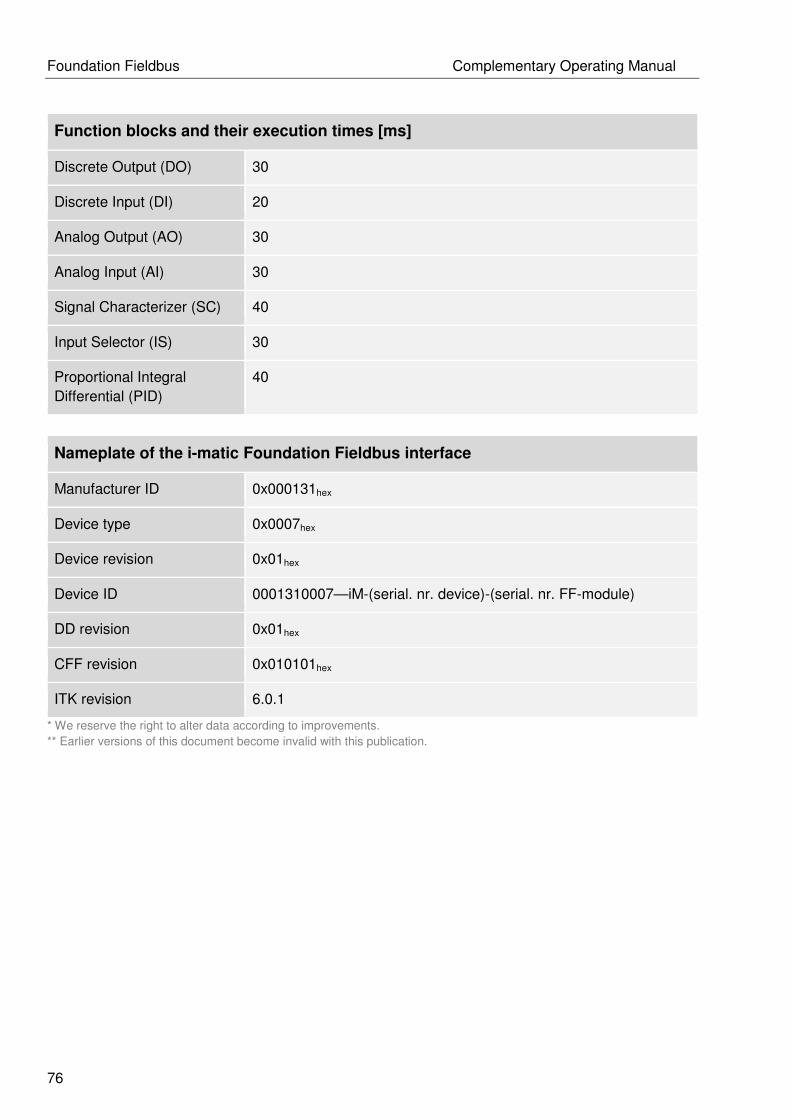
Foundation Fieldbus Complementary Operating Manual
76
Function blocks and their execution times [ms]
Discrete Output (DO) 30
Discrete Input (DI) 20
Analog Output (AO) 30
Analog Input (AI) 30
Signal Characterizer (SC) 40
Input Selector (IS) 30
Proportional Integral
Differential (PID)
40
Nameplate of the i-matic Foundation Fieldbus interface
Manufacturer ID 0x000131hex
Device type 0x0007hex
Device revision 0x01hex
Device ID 0001310007—iM-(serial. nr. device)-(serial. nr. FF-module)
DD revision 0x01hex
CFF revision 0x010101hex
ITK revision 6.0.1
* We reserve the right to alter data according to improvements.
** Earlier versions of this document become invalid with this publication.

Complementary Operating Manual Foundation Fieldbus
77
Notice

Foundation Fieldbus Complementary Operating Manual
78
Notice

Complementary Operating Manual Foundation Fieldbus
79
Notice

Foundation Fieldbus Complementary Operating Manual
80
DREHMO GmbH Zum Eichstruck 10 D-57482 Wenden Tel.: +49 (0) 2762 9850-0 Fax: +49 (0) 2762 9850-105 Web: www.drehmo.com E-Mail: [email protected]


![[MS-AZOD]: Authorization Protocols Overview - Microsoft... · [MS-AZOD]: Authorization Protocols Overview ... Windows Server 2003 operating system introduced a complementary authorization](https://img.pdfslide.us/doc/110x75/5af4e4fd7f8b9a95468e950d/ms-azod-authorization-protocols-overview-microsoft-ms-azod-authorization.jpg)