Embed Size (px)
Citation preview

Compiled and translated 2006 by Curt http://www.curtperedina.com
Adjusting the Pekar K68 for your Dnepr or Ural Adjustment section translated from Pekar K68 manual

Compiled and translated 2006 by Curt http://www.curtperedina.com
Adjusting the Pekar K68 carburetors on your Dnepr or Ural. This document is intended to server as the primer for proper adjustment of the K68’s. It also contains the product specification sheet from Pekar for all of the K68 models. I will talk about the use of different tools used for the synchronization step, but will not go into detail on each tool. As part of this step, I will explain the “old timer” method of synchronizing the 2 carbs without the use of any special tools (placing the bike on the centerstand and using the speedometer to determing carburetor flow). This is very interesting to say the least. Pekar Specifications The following is taken directly from Pekar (translated): K6Е, K68D, K68I, K68M, K68R, K68T, K68U, K68CH
o Horizontal flow o Elliptical diffuser o Cylindrical slide o Centrally located float chamber o Lever type float mechanism and detachable fuel line o Adjustable idle o Adjustable mixture and needle valve o Hands free choke operation o Symmetrical choke and throttle cable o Synchronization port o Float vent system

Compiled and translated 2006 by Curt http://www.curtperedina.com
Carburetor
Transportation means
Engine
Conditional diameter of diffuser (mm)
Diameter of mixing chamber (mm)
The capacity of fuel jet (ml/min)
Mass, is not more (kg)
Overall sizes (mm)
Drive of the starter
К68 А the motorcycle IZH-6.113-03
IZH- 6.113-
03 28 31,5 250 0,55 77,5*81*155 Manual
К68 D the motorcycle "IJ- Jupiter
" 28 31,5 IZH- Ю5 250 0,55 77,5*81*155 Manual
К68 I the motorcycle "the IJ- planet
IZH - П5,
-7.107-10
32 35 280 0,55 77,5*81*157 Manual
К68 М the motorcycle IZH-'.902
IZH - 6.902 32 35 320 0,55 77,5*81*157 Manual
К68 Р “Lynx” 440.76, 440.93 32 35 370 0,55 77,5*81*144 Manual
К68 Т “Ural” Motorcycles
IMZ- 8.128 28 31,5 220 0,55 77,5*81*189 Electric
К68 U “Ural” Motorcycles
IMZ- 8.123 28 31,5 190 0,55 77,5*81*189 Manual
К68 H motorcycle "IJ- chopper"
IZH- 6.113-
05 28 31,5 240 0,55 77,5*81*155 Manual

Compiled and translated 2006 by Curt http://www.curtperedina.com
Specification Chart from russianiron.com
K63Ø 'Dnepr-12'
K750
K63T Dnepr 11/16
K63y Ural
K65T Dnepr
K65y Ural
K68y Ural
Choke size 26 26 28 26 28 28
Bore at flange 28 28 30 28 30 30
Main jet size (cc/min.)
135 163 170 165 170 190
Needle jet size (mm) 2,78 2,78 2,78 2,65 2,65 2,67
Pilot jet (cc/min)
50 50 50 50 50 50
Choke jet (cc/min)
55 55 55 55 55 55
'Diameter opening idle' (note 1)
0,7 0,7 0,7 0,7 0,7 0,7
'Diameter transition opening' (note 2)
1,2 1,2 1,2 1,2 1,2 0,8
Slide type Flat Flat Flat Flat Flat Round

Compiled and translated 2006 by Curt http://www.curtperedina.com
Figure 1
K68

Compiled and translated 2006 by Curt http://www.curtperedina.com
From Figure 1
1. throttle cable; 2. shielding caps; 3. cable guide; 4. cover of choke well; 5. spring of choke; 6. ferrule; 7. housing; 8. slide; 9. cable catch; 10. cable stop; 11. needle of choke; 12. lock of needle; 13. spring of the compression of needle;14. slide bevel; 15. air duct of main system; 16. padding of the cover of float chamber;17. cover of float chamber; 18. sprayer; 19. main fuel jet; 20. dosing tube of the system of idling; 21. stopping washer; 22. drain hole; 23. float activator (tickler); 24. slide (idle) adjusting screw; 25. spring of screw; 26. fuel-feed nipple;
27. balancing port; 28. balancing channel of float chamber; 29. mixture adjustment screw; 30. spring of screw; 31. mixing chamber; 32,34. transitional openings of the system of idling; 33. air duct of idling; 35. saddle of fuel valve; 36. fuel valve in the collection; 37. regulation element; 38. float; 39. channel of starter; 40. axis of floats; 41. air duct; 42. plunger of starter in the collection; 43. ferrule; 44. jet; 45. needle of corrector- enricher; 46. opening dosing; 47. fuel well; 48. the fuel duct of starter; 49. needle of starter; 50. spring of plunger; 51. guide of spring; 52. Choke.
Preparation for K68 Adjustment
1. Make sure the ignition timing is correct 2. Adjust the valves as necessary to ensure proper operation 3. Run the engine to warm it up a bit 4. Adjust the float setting. To do this, remove the carburetors (leave the throttle cables
attached), remove the bowl and turn the carburetor upside down (fuel will spill). The float should look like this:
Adjust as necessary by bending the float support (#37 in Figure 1). Reinstall.
Compiled and translated 2006 by Curt http://www.curtperedina.com
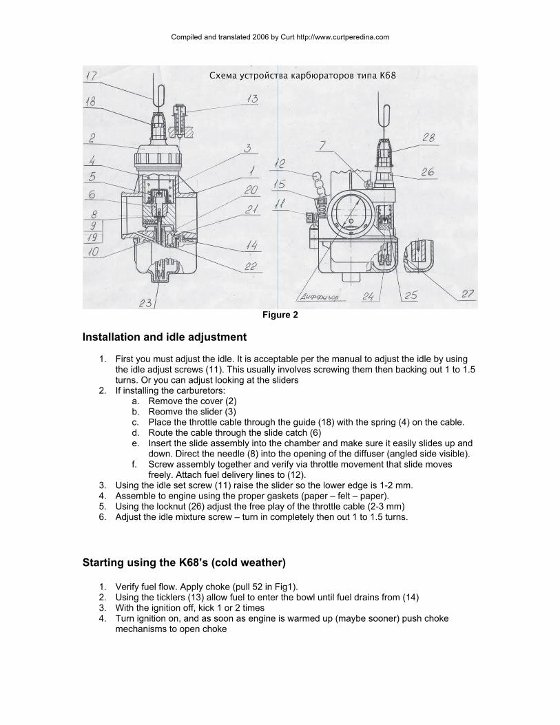
Figure 2
Installation and idle adjustment
1. First you must adjust the idle. It is acceptable per the manual to adjust the idle by using the idle adjust screws (11). This usually involves screwing them then backing out 1 to 1.5 turns. Or you can adjust looking at the sliders
2. If installing the carburetors: a. Remove the cover (2) b. Reomve the slider (3) c. Place the throttle cable through the guide (18) with the spring (4) on the cable. d. Route the cable through the slide catch (6) e. Insert the slide assembly into the chamber and make sure it easily slides up and
down. Direct the needle (8) into the opening of the diffuser (angled side visible). f. Screw assembly together and verify via throttle movement that slide moves
freely. Attach fuel delivery lines to (12). 3. Using the idle set screw (11) raise the slider so the lower edge is 1-2 mm. 4. Assemble to engine using the proper gaskets (paper – felt – paper). 5. Using the locknut (26) adjust the free play of the throttle cable (2-3 mm) 6. Adjust the idle mixture screw – turn in completely then out 1 to 1.5 turns.
�
Starting using the K68’s (cold weather)
1. Verify fuel flow. Apply choke (pull 52 in Fig1). 2. Using the ticklers (13) allow fuel to enter the bowl until fuel drains from (14) 3. With the ignition off, kick 1 or 2 times 4. Turn ignition on, and as soon as engine is warmed up (maybe sooner) push choke
mechanisms to open choke

Compiled and translated 2006 by Curt http://www.curtperedina.com
Idle Adjustment (engine running and warm)
1. Remove one of the spark plug caps, and with the cap shorted, adjust (11) to decrease RPM’s to a point of being minimally steady.
2. Adjust the mixture (15) out until RPM’s decrease. Turn in until RPM’s increase slightly. Then turn in screws ¼ to 1/3 revoultion.
3. Do the same for the second carburetor with the first spark plug cap shorted. 4. With both cylinders, adjust each idle (11) on each carburetor the same amount each until
it’s at a steady, minimal RPM. Use small changes. (at this point you can use your airflow tool to check).
5. Sharply increase, then decrease throttle. Then engine must return to low RPMs smoothly. If the engine goes below limits, readjust (11) from step 4.
Synchronization of the K68
Note: Rather than using the opposite cylinder shorted to test the pull of the live cylinder carburetor, you can use something like a Twinmax connected to the test ports (27 Fig 1). Or, if you have a model without these ports, use a Synchrometer (Appendix 2) held against the face of the carburetor. These tools merely show airflow passing through each carburetor (which is dependent on the position and wear on the slide). If using these tools, it’s not necessary to do the following steps. You wil want to use a throttle guide (Appendix 1), to show airflow at various throttle settings. Using the flow meter of your choice make sure each carburetor is the same at the various throttle settings.
1. Place the motorcycle on the center stand ensuring the rear wheel is suspended 2. Make sure you have large area to work with (safety issues here) 3. Shift into the highest gear with the engine running 4. Short one spark plug cap to the cylinder (using a nail or something in the fins) 5. Increase the speed to 40-50 km/hr 6. Fix the throttle using the throttle (maybe using a throttle stop screw under the throttle
housing). 7. Reconnect other cylinder and using the opposite carburetor determine the speed which
should be the same as the first. 8. Adjust the position of this slide to achieve the referenced speed using the locknut at the
top of the carburetor.
Adjustment of the mixture due to climactic condition changes.
This involves changes to the needle vale (8 and 9 Fig 1) (11 and 12 Fig 2). With the needle moved upward, the mixture is leaned, movement down and the mixture is enriched. Needle movement occurs through removal of the lock and moving the needle to the next groove (coarse adjustment). Fine adjustment occurs through transposition of regulation washer (9 Fig 1) (19 Fig 2).

Compiled and translated 2006 by Curt http://www.curtperedina.com
Special Operating Instructions
Disconnect the fuel before maintenance on K68’s. Must be used with a tightly connected air filter of manufacturers specification only. A modification of filter or manufacturer is not allowed. Fuel used must be cleaned and filtered of all impurities. Carburetor parts must be washed in gasoline only. Washing is not allowed with solvents. After washing, blow with compressed air to dry. Cleaning any of the metering holes (20,21 Fig 2) or nozzle holes (22, 23, 24 Fig 2) with metallic objects (wire, needle, etc.) is not allowed.

Compiled and translated 2006 by Curt http://www.curtperedina.com
Appendix 1 Fixing the throttle and stages of operation

Compiled and translated 2006 by Curt http://www.curtperedina.com
Appendix 2
Synchrometer (an alternative to tuning) Used this on my 912 and it works great
Compiled and translated 2006 by Curt http://www.curtperedina.com
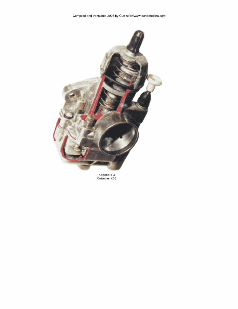
Appendix 3
Cutaway K68

Compiled and translated 2006 by Curt http://www.curtperedina.com

Compiled and translated 2006 by Curt http://www.curtperedina.com