Embed Size (px)
Citation preview

Eaton® Aeroquip® Fluid Conveyance Master Catalog
Competing at the edge of changeThe new standard for fluid conveyance
So, why partner with Eaton?
After all, we know you have choices. You partner with Eaton because every aspect of our business is focused on ensuring your continued success:
• Focused manufacturing that anticipates the needs of a global business environment
• Streamlined product commercialization that deploys tested and qualified products that meet or exceed industry standards
• Product features and attributes that deliver improved performance at a good value
• Safety is treated as a priority within our culture, and yours. Crimp with confidence knowing that Eaton pairs its hoses and fittings after rigorous qualification and testing procedures.
• Dedicated people, who focus daily on meeting your needs
• Engaging marketing and sales programs designed to educate and enable growth in partnership with Eaton
There’s a spirited energy at Eaton. It comes from the alignment of some of the most respected names in fluid power to build a brand you can trust to meet the world’s demand for high-efficiency hydraulic systems.
Our goal is simple: To provide unique fluid power solutions across a range of mobile and stationary markets that keep businesses competing at the leading edge of change.
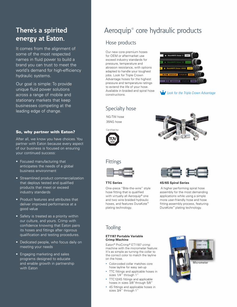
ET1187 Portable Variable Crimp Machine
Eaton® ProCrimp® ET1187 crimp machine with the micrometer feature: It’s as simple as turning the collar to the correct color to match the layline on the hose.
• Color-coded collar matches core hose layline for easy set-up
• TTC fittings and applicable hoses in sizes 1/4” through 1”
• TTC12/4S fittings and applicable hoses in sizes 3/8”through 5/8”
• 4S fittings and applicable hoses in sizes 3/4” through 1”
TTC Series
One-piece “Bite-the-wire” style hose fitting that is qualified with virtually all Aeroquip® one and two wire braided hydraulic hoses, and features DuraKote™ plating technology.
4S/6S Spiral Series
A higher performing spiral hose assembly for the most demanding applications while using a simple more user-friendly hose and hose fitting assembly process, featuring DuraKote™ plating technology.
Our new core premium hoses for OEM or aftermarket use exceed industry standards for pressure, temperature and abrasion resistance, with options adapted to handle your toughest jobs. Look for Triple Crown Advantage hoses for the highest pressure and temperature ratings to extend the life of your hose. Available in braided and spiral hose constructions.
NG-TW hose
35NG hose
Micrometer
Fittings
Hose products
Tooling
Specialty hose
Aeroquip® core hydraulic products
Certified by:
Look for the Triple Crown Advantage
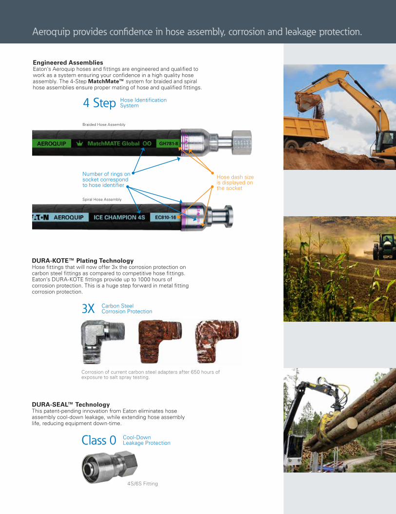
DURA-KOTE™ Plating TechnologyHose fittings that will now offer 3x the corrosion protection on carbon steel fittings as compared to competitive hose fittings. Eaton‘s DURA-KOTE fittings provide up to 1000 hours of corrosion protection. This is a huge step forward in metal fitting corrosion protection.
Engineered AssembliesEaton’s Aeroquip hoses and fittings are engineered and qualified to work as a system ensuring your confidence in a high quality hose assembly. The 4-Step MatchMate™ system for braided and spiral hose assemblies ensure proper mating of hose and qualified fittings.
4 Step Hose Identification System
3X Carbon Steel Corrosion Protection
DURA-SEAL™ TechnologyThis patent-pending innovation from Eaton eliminates hose assembly cool-down leakage, while extending hose assembly life, reducing equipment down-time.
Class 0 Cool-Down Leakage Protection
Number of rings on socket correspond to hose identifier
Hose dash size is displayed on the socket
4S/6S Fitting
Corrosion of current carbon steel adapters after 650 hours of exposure to salt spray testing.
Braided Hose Assembly
Spiral Hose Assembly
Aeroquip provides confidence in hose assembly, corrosion and leakage protection.
AEROQUIP MASTER CATALOG A-HOOV-MC001-E3—August 2017 www.eaton.comA-2
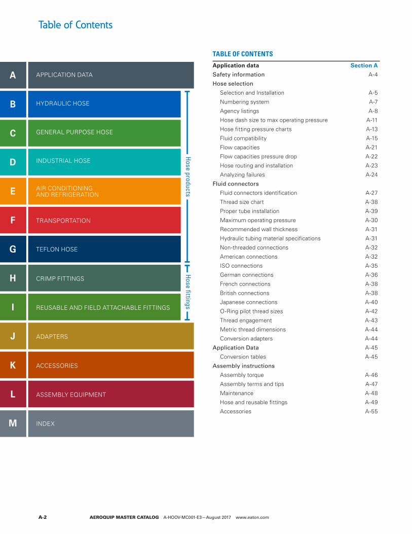
Table of Contents
A
B
C
D
E
F
G
H
I
J
K
L
M
TABLE OF CONTENTS
Application data Section A
Safety information A-4
Hose selection
Selection and Installation A-5
Numbering system A-7
Agency listings A-8
Hose dash size to max operating pressure A-11
Hose fitting pressure charts A-13
Fluid compatibility A-15
Flow capacities A-21
Flow capacities pressure drop A-22
Hose routing and installation A-23
Analyzing failures A-24
Fluid connectors
Fluid connectors identification A-27
Thread size chart A-38
Proper tube installation A-39
Maximum operating pressure A-30
Recommended wall thickness A-31
Hydraulic tubing material specifications A-31
Non-threaded connections A-32
American connections A-32
ISO connections A-35
German connections A-36
French connections A-38
British connections A-38
Japanese connections A-40
O-Ring pilot thread sizes A-42
Thread engagement A-43
Metric thread dimensions A-44
Conversion adapters A-44
Application Data A-45
Conversion tables A-45
Assembly instructions
Assembly torque A-46
Assembly terms and tips A-47
Maintenance A-48
Hose and reusable fittings A-49
Accessories A-55
APPLICATION DATA
HYDRAULIC HOSE
GENERAL PURPOSE HOSE
INDUSTRIAL HOSE
AIR CONDITIONING AND REFRIGERATION
TRANSPORTATION
TEFLON HOSE
CRIMP FITTINGS
REUSABLE AND FIELD ATTACHABLE FITTINGS
ADAPTERS
ACCESSORIES
ASSEMBLY EQUIPMENT
INDEX
Hose products
Hose fittings
AEROQUIP MASTER CATALOG A-HOOV-MC001-E3—August 2017 www.eaton.com A-3
Table of Contents
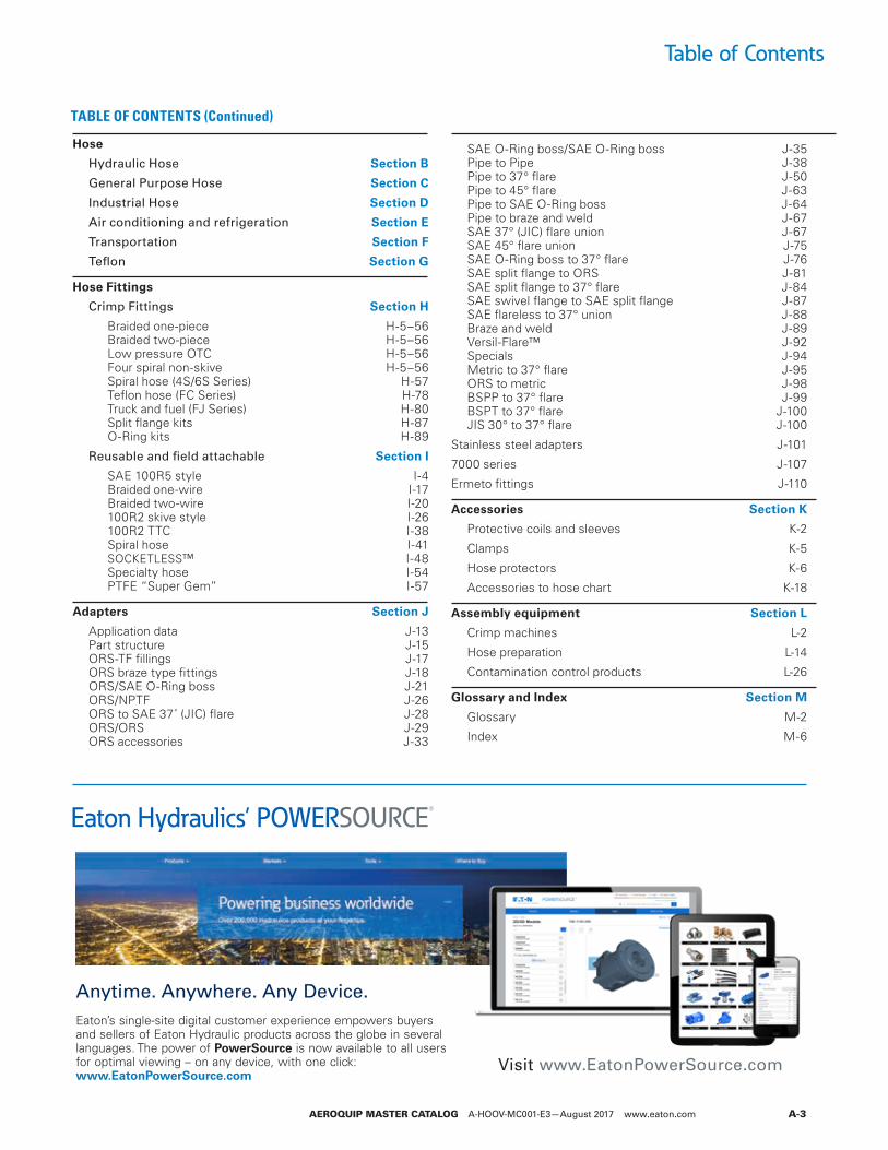
Hose
Hydraulic Hose Section B
General Purpose Hose Section C
Industrial Hose Section D
Air conditioning and refrigeration Section E
Transportation Section F
Teflon Section G
Hose Fittings
Crimp Fittings Section H
Braided one-piece H-5–56 Braided two-piece H-5–56 Low pressure OTC H-5–56 Four spiral non-skive H-5–56 Spiral hose (4S/6S Series) H-57 Teflon hose (FC Series) H-78 Truck and fuel (FJ Series) H-80 Split flange kits H-87 O-Ring kits H-89
Reusable and field attachable Section I
SAE 100R5 style I-4 Braided one-wire I-17 Braided two-wire I-20 100R2 skive style I-26 100R2 TTC I-38 Spiral hose I-41 SOCKETLESS™ I-48 Specialty hose I-54 PTFE “Super Gem” I-57
Adapters Section J
Application data J-13 Part structure J-15 ORS-TF fillings J-17 ORS braze type fittings J-18 ORS/SAE O-Ring boss J-21 ORS/NPTF J-26 ORS to SAE 37˚ (JIC) flare J-28 ORS/ORS J-29 ORS accessories J-33
SAE O-Ring boss/SAE O-Ring boss J-35 Pipe to Pipe J-38 Pipe to 37° flare J-50 Pipe to 45° flare J-63 Pipe to SAE O-Ring boss J-64 Pipe to braze and weld J-67 SAE 37° (JIC) flare union J-67 SAE 45° flare union J-75 SAE O-Ring boss to 37° flare J-76 SAE split flange to ORS J-81 SAE split flange to 37° flare J-84 SAE swivel flange to SAE split flange J-87 SAE flareless to 37° union J-88 Braze and weld J-89 Versil-Flare™ J-92 Specials J-94 Metric to 37° flare J-95 ORS to metric J-98 BSPP to 37° flare J-99 BSPT to 37° flare J-100 JIS 30° to 37° flare J-100
Stainless steel adapters J-101
7000 series J-107
Ermeto fittings J-110
Accessories Section K
Protective coils and sleeves K-2
Clamps K-5
Hose protectors K-6
Accessories to hose chart K-18
Assembly equipment Section L
Crimp machines L-2
Hose preparation L-14
Contamination control products L-26
Glossary and Index Section M
Glossary M-2
Index M-6
Anytime. Anywhere. Any Device.Eaton’s single-site digital customer experience empowers buyers and sellers of Eaton Hydraulic products across the globe in several languages. The power of PowerSource is now available to all users for optimal viewing – on any device, with one click: www.EatonPowerSource.com
Eaton Hydraulics’ POWERSOURCE®
Visit www.EatonPowerSource.com
TABLE OF CONTENTS (Continued)
A
AEROQUIP MASTER CATALOG A-HOOV-MC001-E3—August 2017 www.eaton.comA-4
Accurate processing and prompt delivery of your order depends on easy identification of your requirements. Please order Aeroquip brand parts using correct part numbers as described in this catalog. Inquiries and orders should be directed to your Aeroquip distributor or:
Eaton 14615 Lone Oak Road Eden Prairie, MN 55344 952-937-9800; 888-258-0222; Fax: 952-974-7722 www.eaton.com/hydraulics
Part numbers and dash sizesDash size designates the nominal size in 16th of an inch. This number immediately follows the part number and is separated from it with a dash.
Dimensions Dimensions given in this catalog for Aeroquip products are approximate and should be used for reference only. Exact dimensional information for a given product is subject to change and varying tolerances; contact Eaton directly for full current information.
WARNING
Hose assembliesEaton manufactures the terminal ends of our hose fittings to the appropriate requirements established by the SAE. Therefore, the performance ratings of these hose fittings meet the SAE requirements. It is possible to order a hose assembly with a fitting terminal end that has a performance rating lower than the hose rating. When ordering hose assemblies, please keep the
connecting end performance rating in mind since this may affect overall hose assembly performance. Hose assembly components (hose and fittings) are easily assembled in the field. However, factory assembled reusable and crimped hose assemblies are available. For complete information,contact Eaton.
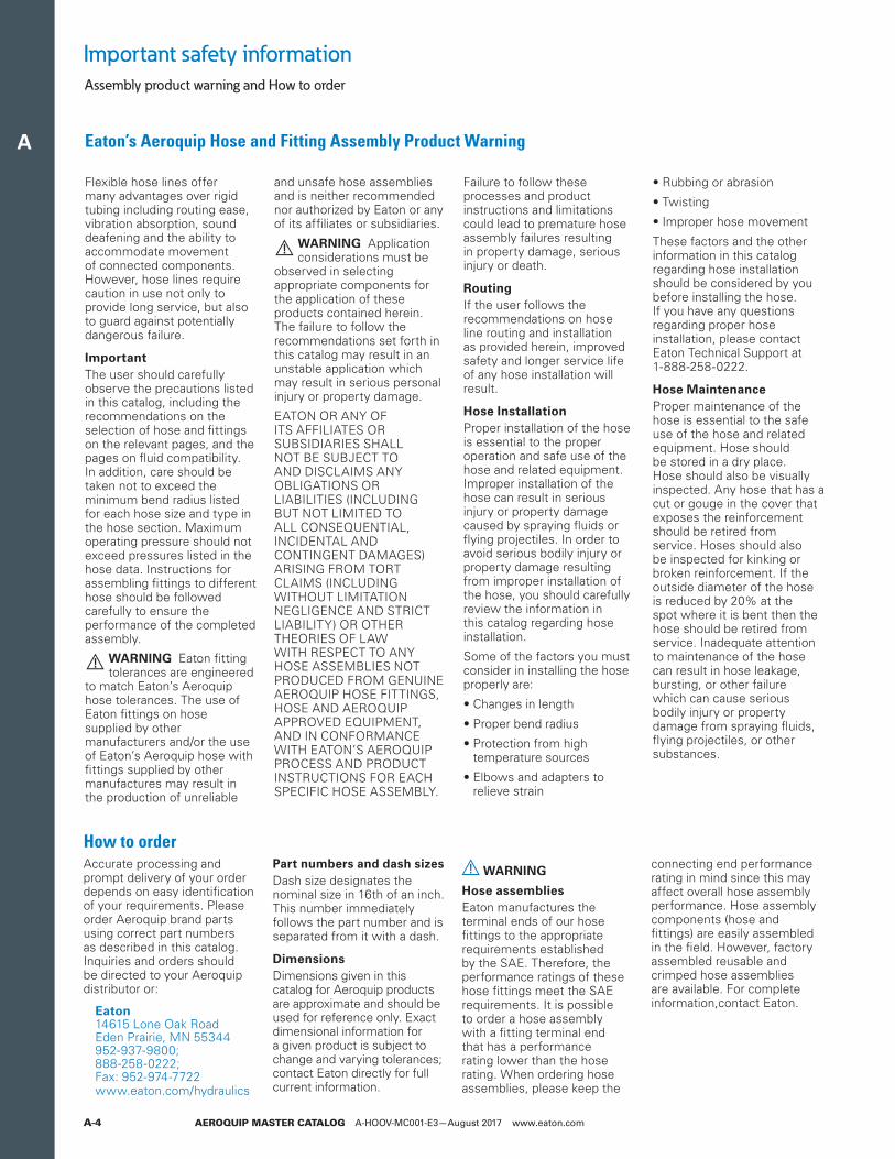
Flexible hose lines offer many advantages over rigid tubing including routing ease, vibration absorption, sound deafening and the ability to accommodate movement of connected components. However, hose lines require caution in use not only to provide long service, but also to guard against potentially dangerous failure.
Important The user should carefully observe the precautions listed in this catalog, including the recommendations on the selection of hose and fittings on the relevant pages, and the pages on fluid compatibility. In addition, care should be taken not to exceed the minimum bend radius listed for each hose size and type in the hose section. Maximum operating pressure should not exceed pressures listed in the hose data. Instructions for assembling fittings to different hose should be followed carefully to ensure the performance of the completed assembly.
WARNING Eaton fitting tolerances are engineered
to match Eaton’s Aeroquip hose tolerances. The use of Eaton fittings on hose supplied by other manufacturers and/or the use of Eaton’s Aeroquip hose with fittings supplied by other manufactures may result in the production of unreliable
and unsafe hose assemblies and is neither recommended nor authorized by Eaton or any of its affiliates or subsidiaries.
WARNING Application considerations must be
observed in selecting appropriate components for the application of these products contained herein. The failure to follow the recommendations set forth in this catalog may result in an unstable application which may result in serious personal injury or property damage.
EATON OR ANY OF ITS AFFILIATES OR SUBSIDIARIES SHALL NOT BE SUBJECT TO AND DISCLAIMS ANY OBLIGATIONS OR LIABILITIES (INCLUDING BUT NOT LIMITED TO ALL CONSEQUENTIAL, INCIDENTAL AND CONTINGENT DAMAGES) ARISING FROM TORT CLAIMS (INCLUDING WITHOUT LIMITATION NEGLIGENCE AND STRICT LIABILITY) OR OTHER THEORIES OF LAW WITH RESPECT TO ANY HOSE ASSEMBLIES NOT PRODUCED FROM GENUINE AEROQUIP HOSE FITTINGS, HOSE AND AEROQUIP APPROVED EQUIPMENT, AND IN CONFORMANCE WITH EATON’S AEROQUIP PROCESS AND PRODUCT INSTRUCTIONS FOR EACH SPECIFIC HOSE ASSEMBLY.
Failure to follow these processes and product instructions and limitations could lead to premature hose assembly failures resulting in property damage, serious injury or death.
Routing If the user follows the recommendations on hose line routing and installation as provided herein, improved safety and longer service life of any hose installation will result.
Hose Installation Proper installation of the hose is essential to the proper operation and safe use of the hose and related equipment. Improper installation of the hose can result in serious injury or property damage caused by spraying fluids or flying projectiles. In order to avoid serious bodily injury or property damage resulting from improper installation of the hose, you should carefully review the information in this catalog regarding hose installation.
Some of the factors you must consider in installing the hose properly are:
• Changes in length
• Proper bend radius
• Protection from high temperature sources
• Elbows and adapters to relieve strain
• Rubbing or abrasion
• Twisting
• Improper hose movement
These factors and the other information in this catalog regarding hose installation should be considered by you before installing the hose. If you have any questions regarding proper hose installation, please contact Eaton Technical Support at 1-888-258-0222.
Hose Maintenance Proper maintenance of the hose is essential to the safe use of the hose and related equipment. Hose should be stored in a dry place. Hose should also be visually inspected. Any hose that has a cut or gouge in the cover that exposes the reinforcement should be retired from service. Hoses should also be inspected for kinking or broken reinforcement. If the outside diameter of the hose is reduced by 20% at the spot where it is bent then the hose should be retired from service. Inadequate attention to maintenance of the hose can result in hose leakage, bursting, or other failure which can cause serious bodily injury or property damage from spraying fluids, flying projectiles, or other substances.
Important safety information
Eaton’s Aeroquip Hose and Fitting Assembly Product Warning
How to order
Assembly product warning and How to order
A
AEROQUIP MASTER CATALOG A-HOOV-MC001-E3—August 2017 www.eaton.com A-5
Hose selectionGeneral hose selection information
1. ScopeHose (also includes hose assemblies) has a finite life and there are a number of factors which will reduce its life. This recommended practice is intended as a guide to assist system designers and/or users in the selection, installation, and maintenance of hose.
The designers and users must make a systematic review of each application and then select, install, and maintain the hose to fulfill the requirements of the application. The following are general guidelines and are not necessarily a complete list.
Warning: improper selection, installation, or maintenance may result in premature failures, bodily injury, or property damage.
2. References
2.1 Applicable documentsThe following publications form a part of this specification to the extent specified herein. The latest issue of SAE publications shall apply.
2.1.1 SAE publicationsAvailable from SAE, 400 Commonwealth Drive, Warrendale, PA 15096-0001.
J516—Hydraulic hose fittings
J517—Hydraulic hose
3. SelectionThe following is a list of factors which must be considered before final hose selection can be made.
3.1 PressureAfter determining the system pressure, hose selection must be made so that the recommended maximum operating pressure is equal to or greater than the system pressure. Surge pressures higher than the maximum operating pressure will shorten hose life and must be taken into account by the hydraulic designer.
3.2 SuctionHoses used for suction applications must be selected to insure the hose will withstand the negative pressure of the system.
3.3 TemperatureCare must be taken to insure that fluid and ambient temperatures, both static and transient, do not exceed the limitations of the hose. Special care must be taken when routing near hot manifolds.
3.4 Fluid compatibilityHose selection must assure compatibility of the hose tube, cover and fittings with the fluid used. Additional caution must be observed in hose selection for gaseous applications.
3.5 SizeTransmission of power by means of pressurized fluid varies with pressure and rate of flow. The size of the components must be adequate to keep pressure losses to a minimum and avoid damage to the hose due to heat generation or excessive turbulence.
3.6 RoutingAttention must be given to optimum routing to minimize inherent problems.
3.7 EnvironmentCare must be taken to insure that the hose and fittings are either compatible with or protected from the environment to which they are exposed. Environmental conditions such as ultraviolet light, ozone, salt water, chemicals, and air pollutants can cause degradation and premature failure and, therefore, must be considered.
3.8 Mechanical loadsExternal forces can significantly reduce hose life. Mechanical loads which must be considered include excessive flexing, twist, kinking, tensile or side loads, bend radius, and vibration. Use of swivel-type fittings or adapters may be required to insure no twist is put into the hose. Unusual applications may require special testing prior to hose selection.
3.9 AbrasionWhile hose is designed with a reasonable level of abrasion resistance, care must be taken to protect the hose from excessive abrasion which can result in erosion, snagging and cutting of the hose cover. Exposure of the reinforcement will significantly accelerate hose failure.
3.10 Proper end fittingCare must be taken to insure proper compatibility exists between the hose and coupling selected based on the manufacturer’s recommendations substantiated by testing to industry standards such as SAE J517. End fitting components from one manufacturer are usually not compatible with end fitting components supplied by another manufacturer (i.e., using a hose fitting nipple from one manufacturer with a hose socket from another manufacturer). It is the
responsibility of the fabricator to consult the manufacturer’s written instructions or the manufacturer directly for proper end fitting componentry.
3.11 LengthWhen establishing proper hose length, motion absorption, hose length changes due to pressure, as well as hose and machine tolerances must be considered.
3.12 Specifications and standardsWhen selecting hose, government, industry and manufacturers’ specifications and recommendations must be reviewed as applicable.
3.13 Hose cleanlinessHose components vary in cleanliness levels. Care must be taken to insure that the assemblies selected have an adequate level of cleanliness for the application.
3.14 Electrical conductivityCertain applications require that hose be nonconductive to prevent electrical current flow. Other applications require the hose to be sufficiently conductive to drain off static electricity. Hose and fittings must be chosen with these needs in mind.
4. InstallationAfter selection of proper hose, the following factors must be considered by the installer.
4.1 Pre-installation inspection
Prior to installation, a careful examination of the hose must be performed. All components must be checked for correct style, size and length. In addition, the hose must be examined for cleanliness, I.D. obstructions, blisters, loose cover, or any other visible defects.
Selection, installation and maintenance of hose and assemblies
The following recommendations on selection, installation and maintenance of hose assemblies were established by the SAE in 1991. Please read these general instructions carefully. More detailed information on many of these subjects is covered in this catalog.
A
AEROQUIP MASTER CATALOG A-HOOV-MC001-E3—August 2017 www.eaton.comA-6
4.2 Follow manufacturers’ assembly instructionsHose assemblies may be fabricated by the manufacturer, an agent for or customer of the manufacturer, or by the user. Fabrication of permanently attached fittings to hydraulic hose requires specialized assembly equipment. Field attachable fittings (screw style and segment clamp style) can usually be assembled without specialized equipment although many manufacturers provide equipment to assist in the operation.
SAE J517 hose from one manufacturer is usually not compatible with SAE J516 fittings supplied by another manufacturer. It is the responsibility of the fabricator to consult the manufacturer’s written assembly instructions or the manufacturers directly before intermixing hose and fittings from two manufacturers. Similarly, assembly equipment from one manufacturer is usually not interchangeable with that of another manufacturer. It is the responsibility of the fabricator to consult the manufacturer’s written instructions or the manufacturer directly for proper assembly equipment. Always follow the manufacturer’s instructions for proper preparation and fabrication of hose assemblies.
4.3 Minimum bend radiusInstallation at less than minimum bend radius may significantly reduce hose life. Particular attention must be given to preclude sharp bending at the hose/fitting juncture.
4.4 Twist angle and orientationHose installations must be such that relative motion of machine components produces bending of the hose rather than twisting.
4.5 SecurementIn many applications, it may be necessary to restrain, protect, or guide the hose to protect it from damage by unnecessary flexing, pressure surges, and contact with other mechanical components. Care must be taken to insure such restraints do not introduce additional stress or wear points.
4.6 Proper connection of portsProper physical installation of the hose requires a correctly installed port connection while insuring that no twist or torque is put into the hose.
4.7 Avoid external damageProper installation is not complete without insuring that tensile loads, side loads, kinking, flattening, potential abrasion, thread damage, or damage to sealing surfaces are corrected or eliminated.
4.8 System check outAfter completing the installation, all air entrapment must be eliminated and the system pressurized to the maximum system pressure and checked for proper function and freedom from leaks.
ote:N Avoid potential hazardous areas while testing.
5. MaintenanceEven with proper selection and installation, hose life may be significantly reduced without a continuing maintenance program. Frequency should be determined by the severity of the application and risk potential. A maintenance program should include the following as a minimum.
5.1 Hose storageHose products in storage can be affected adversely by temperature, humidity, ozone, sunlight, oils, solvents, corrosive liquids and fumes, insects, rodents and radioactive materials. Storage areas should be relatively cool and dark and free of dust, dirt, dampness and mildew.
5.2 Visual inspectionAny of the following conditions requires replacement of the hose:
a. Leaks at fitting or in hose (leaking fluid is a fire hazard)
b. Damaged, cut, or abraded cover (any reinforcement exposed)
c. Kinked, crushed, flattened, or twisted hose
d. Hard, stiff, heat cracked or charred hose
e. Blistered, soft, degraded, or loose cover
f. Cracked, damaged, or badly corroded fittings
g. Fitting slippage on hose
5.3 Visual inspectionThe following items must be tightened, repaired, or replaced as required:
a. Leaking port conditionsb. Clamps, guards, shieldsc. Remove excessive dirt buildupd. System fluid level,fluid type,
and any air entrapment
5.4 Functional testOperate the system at maximum operating pressure and check for possible malfunctions and freedom from leaks.
ote:N Avoid potential hazardous areas while testing.
5.5 Replacement intervalsSpecific replacement intervals must be considered based on previous service life, government or industry recommendations, or when failures could result in unacceptable down time, damage, or injury risk.
Hose selectionGeneral hose selection information
Selection, installation and maintenance of hose and assemblies
The following recommendations on selection, installation and maintenance of hose assemblies were established by the SAE in 1991. Please read these general instructions carefully. More detailed information on many of these subjects is covered in this catalog.
A
AEROQUIP MASTER CATALOG A-HOOV-MC001-E3—August 2017 www.eaton.com A-7
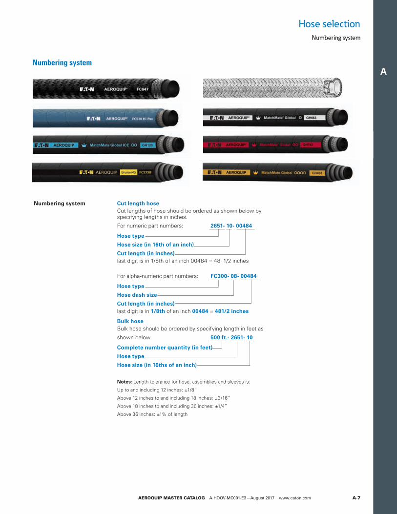
Hose selectionNumbering system
Numbering system Cut length hoseCut lengths of hose should be ordered as shown below by specifying lengths in inches.
For numeric part numbers: 2651- 10- 00484
Hose type
Hose size (in 16th of an inch)
Cut length (in inches) last digit is in 1/8th of an inch 00484 = 48 1/2 inches
For alpha-numeric part numbers: FC300- 08- 00484
Hose type
Hose dash size
Cut length (in inches) last digit is in 1/8th of an inch 00484 = 481/2 inches
Bulk hoseBulk hose should be ordered by specifying length in feet as
shown below. 500 ft.- 2651- 10
Complete number quantity (in feet)
Hose type
Hose size (in 16ths of an inch)
otes:N Length tolerance for hose, assemblies and sleeves is:
Up to and including 12 inches: ±1/8”
Above 12 inches to and including 18 inches: ±3/16”
Above 18 inches to and including 36 inches: ±1/4”
Above 36 inches: ±1% of length
Numbering system

A
AEROQUIP MASTER CATALOG A-HOOV-MC001-E3—August 2017 www.eaton.comA-8
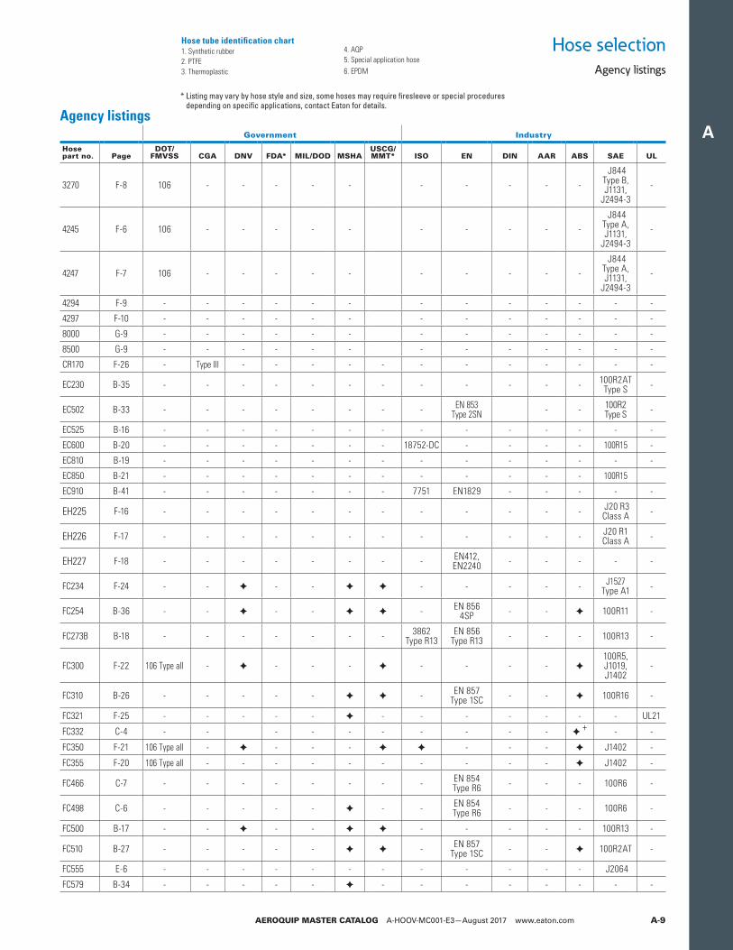
Hose selection
Agency listings
Agency listings
Government agenciesDOT/FMVSS US Department of Transportation,Federal Motor
Vehicle Safety Standard
FDA US Food and Drug Administration (tubes only)
MIL/DOD US Military Specification, Dept. of Defense
MSHA US Mine Safety and Health Administration
USCG/MMT US Coast Guard, Merchant Marine Technical (SAE J1942 has replaced USCG approval)
DNV Det Norske (Norwegian) Veritas
CGA Canadian Gas AssociationThe listings below are intended only as guides in identifying which Aeroquip®
hoses comply with requirements of various agencies. For current and complete information,contact Eaton.
Industry agenciesAAR American Association of Railroads
DIN Deutsche (German) Industrial Norme (Replaced by EN)
EN Committee for European Normalization
ABS American Bureau of Shipping
SAE Society of Automotive Engineers
UL Underwriters Laboratories
ISO International Standards Organization
✦ Approved details available from Eaton
* Listing may vary by hose style and size, some hoses may require firesleeve or special procedures depending on specific applications, contact Eaton for details.
Government Industry
Hosepart no. Page
DOT/FMVSS CGA DNV FDA* MIL/DOD MSHA
USCG/MMT* ISO EN DIN AAR ABS SAE UL
1503 C-9 106 Type aII - - - - - - - - - - - 100R5, J1402 -
1531 F-15 - - - - - - - - - - M618 - - -
15CA F-5 106 - - - - - - - - - - - SAE J844 Type B -
2550 F-15 106 Type aII - - - - - ✦ - - - - - J1402 -
2554 F-15 - - - - - - - - - - - J1402 -
2556 C-5 - - ✦ - - ✦ - - - - - - 20R2 Type 1 -
2565 C-5 - - - -MIL-H-13444 Type I
- - - - - - 20R2 -
2570 F-14 106 Type aII - - - - - ✦ - - - - - J1402 -
2580 C-8 - - - - MIL-H-24136/3 ✦ ✦ - - - - - - -
2583 C-7 - - - - - ✦ - - EN 854 Type R3 - - - 100R3 -
2651 C-10 - - ✦ - - ✦ ✦ - - - - - 100R5 -
2661 B-43 - - - - ✦ ✦ - - - - ✦ + 100R4 -
2681 B-29 - - ✦ - - ✦ ✦1436
Type 1STEN 853
Type 1ST20 022
Type 1ST - - 100R1A -
2781 B-30 - - ✦ - - ✦ ✦1436
Type 1STEN 853
Type 2ST20 022
Type 2ST - - 100R2A -
2807 G-8 - - ✦ - - - ✦ - - - - - 100R14A -
30CT B-49,52 - - - - - - - - - - - 100R18 -
3130 B-44,52 - - - - - - - - - - - 100R7 -
3740 B-45 - - - - - - - - - - - 100R7 -
3E80 B-48 - - - - - - - - - - - 100R8 -
3R80 B-47 - - - - - - - - - - - 100R8 -
3SCE F-5 106 - - - - - - - - - - J844 Type B -
3V10 B-50 - - - - - - - - - - - - -
3VE0 B-51 - - - - - - - - - - - - -
35FH F-13 - - - - - - - - - - - J30R6, J30R9, J30R11, J1527B1
-
35NG F-27 - - - - - - - - - - - -
37AL B-46,52 - - - - - - - - - - - 100R7 -
A
AEROQUIP MASTER CATALOG A-HOOV-MC001-E3—August 2017 www.eaton.com A-9
Hose selectionAgency listings
Agency listings* Listing may vary by hose style and size, some hoses may require firesleeve or special procedures
depending on specific applications, contact Eaton for details.
Government Industry
Hosepart no. Page
DOT/FMVSS CGA DNV FDA* MIL/DOD MSHA
USCG/MMT* ISO EN DIN AAR ABS SAE UL
3270 F-8 106 - - - - - - - - - - J844
Type B, J1131,
J2494-3-
4245 F-6 106 - - - - - - - - - - J844
Type A, J1131,
J2494-3-
4247 F-7 106 - - - - - - - - - - J844
Type A, J1131,
J2494-3-
4294 F-9 - - - - - - - - - - - - -
4297 F-10 - - - - - - - - - - - - -
8000 G-9 - - - - - - - - - - - - -
8500 G-9 - - - - - - - - - - - - -
CR170 F-26 - Type III - - - - - - - - - - - -
EC230 B-35 - - - - - - - - - - - - 100R2AT Type S -
EC502 B-33 - - - - - - - - EN 853 Type 2SN - - 100R2
Type S -
EC525 B-16 - - - - - - - - - - - - - -
EC600 B-20 - - - - - - - 18752-DC - - - - 100R15 -
EC810 B-19 - - - - - - - - - - - - - -
EC850 B-21 - - - - - - - - - - - - 100R15
EC910 B-41 - - - - - - - 7751 EN1829 - - - - -
EH225 F-16 - - - - - - - - - - - - J20 R3 Class A -
EH226 F-17 - - - - - - - - - - - - J20 R1 Class A -
EH227 F-18 - - - - - - - - EN412, EN2240 - - - - -
FC234 F-24 - - ✦ - - ✦ ✦ - - - - - J1527 Type A1 -
FC254 B-36 - - ✦ - - ✦ ✦ - EN 856 4SP - - ✦ 100R11 -
FC273B B-18 - - - - - - - 3862Type R13
EN 856Type R13 - - - 100R13 -
FC300 F-22 106 Type aII - ✦ - - - ✦ - - - - ✦100R5,J1019,J1402
-
FC310 B-26 - - - - - ✦ ✦ - EN 857Type 1SC - - ✦ 100R16 -
FC321 F-25 - - - - - ✦ - - - - - - - UL21
FC332 C-4 - - - - - - - - - - ✦ + - -
FC350 F-21 106 Type aII - ✦ - - - ✦ ✦ - - - ✦ J1402 -
FC355 F-20 106 Type aII - - - - - - - - - - ✦ J1402 -
FC466 C-7 - - - - - - - - EN 854Type R6 - - - 100R6 -
FC498 C-6 - - - - - ✦ - - EN 854Type R6 - - - 100R6 -
FC500 B-17 - - ✦ - - ✦ ✦ - - - - - 100R13 -
FC510 B-27 - - - - - ✦ ✦ - EN 857Type 1SC - - ✦ 100R2AT -
FC555 E-6 - - - - - - - - - - - - J2064
FC579 B-34 - - - - - ✦ - - - - - - - -
Hose tube identification chart1. Synthetic rubber2. PTFE3. Thermoplastic
4. AQP5. Special application hose6. EPDM
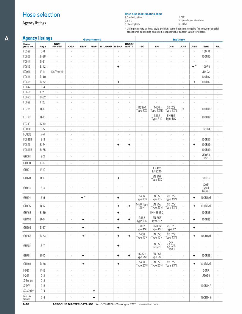
A
AEROQUIP MASTER CATALOG A-HOOV-MC001-E3—August 2017 www.eaton.comA-10
Hose selection
Agency listings
Agency listings
Government Industry
Hosepart no. Page
DOT/FMVSS CGA DNV FDA* MIL/DOD MSHA
USCG/MMT* ISO EN DIN AAR ABS SAE UL
FC598 C-6 - - - - - - - - - - - - 100R6 -
FC606 B-38 - - - - - - - - - - - - 100R15
FC611 B-31 - - - - - - - - - - - - - -
FC619 B-42 - - - - - ✦ - - - - - ✦ + 100R4 -
EC038 F-14 106 Type aII - - - - - - - - - - - J1402 -
FC636 B-40 - - - - - - - - - - - - 100R12 -
FC639 B-22 - - - - - ✦ - - - - - ✦ 100R17 -
FC647 C-4 - - - - - - - - - - - - - -
FC650 F-23 - - - - - - - - - - - - - -
FC693 B-32 - - - - - - - - - - - - - -
FC699 F-23 - - - - - - - - - - - - - -
FC735 B-11 - - - - - - - 11237-1 Type 2SC
1436Type 2SN§
20 022Type 2SN ‡ - 100R16 -
FC736 B-15 - - - - - - - - 3862Type R12
EN856Type R12 - - 100R12 -
FC740 G-10 - - - - - - - - - - - - - -
FC800 E-5 - - - - - - - - - - - - J2064 -
FC802 E-4 - - - - - - - - - - - - - -
FC839B B-8 - - - - - - - - - - - - 100R17 -
FC849 B-24 - - - - - ✦ ✦ - - - - ✦ 100R19 -
FC849B B-25 - - - - - - - - - - 100R19 -
GH001 E-3 - - - - - - - - - - - - J2064 Type E -
GH100 F-19 - - - - - - - - - - - - - -
GH101 F-19 - - - - - - - - EN412, EN2240 - - - - -
GH120 B-13 - - - - - ✦ - - EN 857 Type 2SC - - - 100R16 -
GH134 E-4 - - - - - - - - - - - -J2064 Type E Class 1
-
GH194 B-9 - - ✦ + - - ✦ - 1436Type 1SN
EN 853Type 1SN
20 022Type 1SN - ✦ 100R1AT -
GH195 B-12 - - - - - ✦ ✦1436 Type
2SNEN 853
Type 2SN20 022
Type 2SN - ✦ 100R2AT -
GH466 B-39 - - - - - ✦ - - EN 45545-2 - - - 100R15 -
GH493 B-14 - - ✦ - - ✦ ✦3862
Type R12EN 856TypeR12 - - ✦ 100R12 -
GH506 B-37 - - ✦ - - ✦ - 3862Type 4SH
EN856Type 4SH
20 023Type T2 - ✦ - -
GH663 B-23 - - ✦ - - ✦ ✦1436
Type 1SNEN 853
Type 1SN20 022
Type 1SN - ✦ 100R1AT -
GH681 B-7 - - - - - ✦ - - EN 853 Type 1
DIN 20 022Type 1
- - - -
GH781 B-10 - - ✦ - - ✦ ✦11237-1
Type 2SCEN 857
Type 2SC - - ✦ 100R16 -
GH793 B-28 - - ✦ - - ✦ - 1436Type 2SN
EN 853Type 2SN
20 022Type 2SN - ✦ 100R2AT -
H057 F-12 - - - - - - - - - - - - 30R7 -
H201 C-3 - - - - - - - - - - - - J2064 -
S-Series G-3 - - - - - - - - - - - - - -
S-TW G-5 - - - - - - - - - - - - 100R14A -
SC-Series G-4 - - - ✦ - - - - - - - - - -
SC-TW Series G-6 - - - ✦ - - - - - - - - 100R14B -
* Listing may vary by hose style and size, some hoses may require firesleeve or special procedures depending on specific applications, contact Eaton for details.
Hose tube identification chart1. Synthetic rubber2. PTFE3. Thermoplastic
4. AQP5. Special application hose6. EPDM
A
AEROQUIP MASTER CATALOG A-HOOV-MC001-E3—August 2017 www.eaton.com A-11
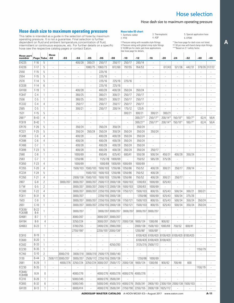
Hose dash size to maximum operating pressure
Hose selection
Hose part number Page Tube
Hose-02 -03 -04 -05 -06 -08 -10 -12 -16 -20 -24 -32 -40 -48
EH225 F-16 5 - - 400/28 300/21 250/17 250/17 250/17 200/14 - - - - - -EH226 F-17 5 - - - 1080/75 1060/73 872/60 797/55 764/53 - 617/43 521/36 442/31 379/26 317/222550 F-15 5 - - - - 225/16 - - - - - - - - -2554 F-15 5 - - - - 225/16 - - - - - - - - -2570 F-14 5 - - - - 225/16 225/16 225/16 - - - - - - -EC038 F-14 6 - - - - 225/16 225/16 - - - - - - - -GH100 F-19 1 - - 400/28 - 400/28 400/28 350/24 350/24 - - - - - -FC647 C-4 1 - - 360/25 - 300/21 300/21 250/17 250/17 - - - - - -2556 C-5 1 - - 360/25 - 300/21 300/21 250/17 250/17 - - - - - -FC332 C-4 4 - - 250/17 - 250/17 250/17 250/17 250/17 - - - - - -2565 C-5 1 - - 300/21 - 250/17 200/14 175/12 125/9 - - - - - -1531 F-15 5 - - - - - - 300/21 300/21 300/21 300/21 - - - -2661* B-43 4 - - - - - - - 300/21†† 250/17†† 200/14†† 150/10†† 100/7†† 62/4 56/4FC619 B-42 1 - - - - - - - 300/21†† 250/17†† 200/14†† 150/10†† 100/7†† 62/4 56/4CR170 F-26 5 - - 350/24 - 350/24 350/24 - 350/24 - - - - - -FC321 F-25 5 - - 350/24 350/24 350/24 350/24 350/24 350/24 350/24 - - - - -FC498 C-6 4 - - 400/28 - 400/28 400/28 350/24 350/24 - - - - - -FC598 C-6 4 - - 400/28 - 400/28 400/28 350/24 350/24 - - - - - -FC466 C-7 1 - - 400/28 - 400/28 400/28 350/24 350/24 - - - - - -FC699 F-23 5 - - 400/28 - 400/28 400/28 350/24 350/24 250/17 - - - - -2580 C-8 1 - - 1000/69 - 650/45 625/43 600/41 550/38 500/34 450/31 400/28 350/24 - -2583 C-7 1 - - 1250/86 - 1125/78 1000/69 - 750/52 565/39 375/26 - - -FC650 F-23 4 - - 1000/69 - 1000/69 1000/69 1000/69 1000/69 - - - - -FC355 F-20 4 - - 1500/103 1500/103 1500/103 1250/86 1250/86 750/52 400/28 300/21 250/17 200/14 - -FC234 F-24 5 - - - 1500/103 1500/103 1250/86 1250/86 750/52 400/28 - - - - -FC350 F-21 4 - - 2000/138 1500/103 1500/103 1250/86 1250/86 750/52 400/28 300/21 250/17 - - -2807 G-8 2 - 3000/207 3000/207 3000/207 2500/172 2000/138 1500/103 1200/83 1000/69 625/43 - - - -S-TW G-5 2 - - 3000/207 3000/207 2500/172 2000/138 1500/103 1200/83 1000/69 - - - - -FC300 F-22 4 - - 3000/207 3000/207 2250/155 2000/138 1750/121 1500/103 800/55 625/43 500/34 300/21 300/21 -FC611 B-31 6 - - 3000/207 - 2250/155 2000/138 - 1250/86 1000/69 625/43 500/34 375/26 - -1503 C-9 1 - - 3000/207 3000/207 2250/155 2000/138 1750/121 1500/103 800/55 625/43 500/34 350/24 350/24 -2651 C-10 1 - - 3000/207 3000/207 2250/155 2000/138 1750/121 1500/103 800/55 625/43 500/34 350/24 350/24 -
FC639/ FC839B
B-22 B-8 1 - 3000/207 - 3000/207 3000/207 3000/207 3000/207 3000/207 - - - - -
GH681 B-7 1 - - 3000/207 - 3000/207 3000/207 - - - - - - - -GH194 B-9 4 - - 3250/224 - 3000/207 2500/172 2000/138 1800/124 1300/90 900/62 - - - -GH663 B-23 1 - - 3700/255 - 3400/235 2900/200 - 2000/138 1500/103 1000/69 750/52 600/41 - -
- - 2750/190† - 2250/155† 2000/138† - 1250/86† 1000/69† - - - - -
EC810 B-19 1 - - - - - - - 6100/420 6100/420 6100/420 6100/420 6100/420 - -
EC600 B-20 1 - - - - - - - 6100/420 6100/420 6100/420 - - - -
EC502 B-33 1 - - - - - 4250/293 - 3125/215 2500/172 - - - - -
EC230 B-35 1 - - - - - - - - - - - - 1150/79FC740 G-10 2 3000/210 3000/210 3000/210 2500/175 2000/140 - - - - - - - -
3130 B-44 3 2500/172 3000/207 3000/207 2500/172 2250/155 2000/138 - 1250/86 1000/692681 B-29 1 - 4000/276 3250/224 3250/224 3000/207 2500/172 2000/138 1800/124 1300/90 900/62 700/48 600 - -EC230 B-35 1 - - - - - - - - - - - 1150/79 -FC849/ FC849B B-24 0 - - 4000/276 - 4000/276 4000/276 4000/276 4000/276 - - - - -
FC310 B-26 1 - - 5000/345 - 4000/276 3500/241 - - - - - - -FC693 B-32 6 - - 5000/345 - 5000/345 4500/310 4000/276 3500/241 2800/193 2300/159 2000/138 1500/103 - -GH120 B-13 1 - - 6000/414 - 4000/276 3500/241 2750/190 2250/155 2000/138 1625/112 - - - -
Hose dash size to maximum operating pressureThis table is intended as a guide in the selection of hose by maximum operating pressure. It is not a guarantee. Final selection is further dependent on fluid and ambient temperature,concentration of fluid, intermittent or continuous exposure, etc. For further details on a specific hose see the respective catalog pages or contact Eaton.
† Pressure rating with reusable style fittings.‡ Pressure rating with global crimp style fittings.§ 10,000 psi for static jack hose applications. See hose page for details.
* See hose page for dash sizes not listed.†† 50 psi max with band clamp style fittings.***Based on 2:1 safety factor.
Hose tube ID chart1. Synthetic rubber2. PTFE
3. Thermoplastic4. AQP
5. Special application hose6. EPDM
A
AEROQUIP MASTER CATALOG A-HOOV-MC001-E3—August 2017 www.eaton.comA-12
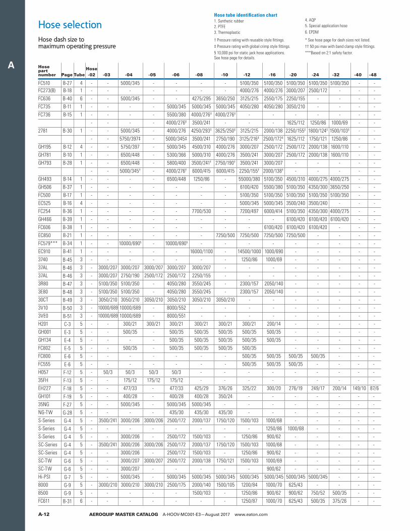
Hose dash size to maximum operating pressure
Hose selection
Hose part number Page Tube
Hose-02 -03 -04 -05 -06 -08 -10 -12 -16 -20 -24 -32 -40 -48
FC510 B-27 4 - - 5000/345 - - - - 5100/350 5100/350 5100/350 5100/350 5100/350 - -FC273(B) B-18 1 - - - - - - - 4000/276 4000/276 3000/207 2500/172 - - -FC636 B-40 6 - - 5000/345 - - 4275/295 3650/250 3125/215 2550/175 2250/155 - - - -FC735 B-11 1 - - - - 5000/345 5000/345 5000/345 4050/280 4050/280 3050/210 - - - -FC736 B-15 1 - - - - 5500/380 4000/276‡ 4000/276‡ - - - - - - -
- - - - 4000/276‡ 3500/241 - - - 1625/112 1250/86 1000/69 - -2781 B-30 1 - - 5000/345 - 4000/276 4250/293‡ 3625/250‡ 3125/215 2000/138 2250/155‡ 1800/124‡ 1500/103‡ - -
- - 5750/397‡ - 5000/345‡ 3500/241 2750/190 3125/216‡ 2500/172‡ 1625/112 1750/121 1250/86 - -GH195 B-12 4 - - 5750/397 - 5000/345 4500/310 4000/276 3000/207 2500/172 2500/172 2000/138 1600/110 - -GH781 B-10 1 - - 6500/448 - 5300/366 5000/310 4000/276 3500/241 3000/207 2500/172 2000/138 1600/110 - -GH793 B-28 1 - - 6500/448 - 5800/400 3500/241† 2750/190† 3500/241 3000/207 - - - - -
- - 5000/345† - 4000/276† 6000/415 6000/415 2250/155† 2000/138† - - - - -GH493 B-14 1 - - - - 6500/448 1250/86 - 55000/380 5100/350 4500/310 4000/275 4000/275 - -GH506 B-37 1 - - - - - - - 6100/420 5500/380 5100/350 4350/300 3650/250 - -FC500 B-17 1 - - - - - - - 5100/350 5100/350 5100/350 5100/350 5100/350 - -EC525 B-16 4 - - - - - - - 5000/345 5000/345 3500/240 3500/240 - - -FC254 B-36 1 - - - - - 7700/530 - 7200/497 6000/414 5100/350 4350/300 4000/275 - -GH466 B-39 1 - - - - - - - - - 6100/420 6100/420 6100/420 - -FC606 B-38 1 - - - - - - - - 6100/420 6100/420 6100/420 - - -EC850 B-21 1 - - - - - - 7250/500 7250/500 7250/500 7250/500 - - - -FC579*** B-34 1 - - 10000/690§ - 10000/690§ - - - - - - - - -EC910 B-41 1 - - - - - 16000/1100 - 14500/1000 1000/690 - - - - -3740 B-45 3 - - - - - - - 1250/86 1000/69 - - - - -37AL B-46 3 - 3000/207 3000/207 3000/207 3000/207 3000/207 - - - - - - - -37AL B-46 3 - 3000/207 2750/190 2500/172 2500/172 2250/155 - - - - - - - -3R80 B-47 3 - 5100/350 5100/350 - 4050/280 3550/245 - 2300/157 2050/140 - - - - -3E80 B-48 3 - 5100/350 5100/350 - 4050/280 3550/245 - 2300/157 2050/140 - - - - -30CT B-49 3 - 3050/210 3050/210 3050/210 3050/210 3050/210 3050/210 - - - - - - -3V10 B-50 3 - 10000/689 10000/689 - 8000/552 - - - - - - - - -3VE0 B-51 3 - 10000/689 10000/689 - 8000/551 - - - - - - - - -H201 C-3 5 - - 300/21 300/21 300/21 300/21 300/21 300/21 200/14 - - - - -GH001 E-3 5 - - 500/35 - 500/35 500/35 500/35 500/35 500/35 - - - - -GH134 E-4 5 - - - - 500/35 500/35 500/35 500/35 500/35 - - - - -FC802 E-5 5 - - 500/35 - 500/35 500/35 500/35 500/35 - - - - -FC800 E-6 5 - - - - - - - 500/35 500/35 500/35 500/35 - - -FC555 E-6 5 - - - - - - - 500/35 500/35 500/35 - - - -H057 F-12 5 - 50/3 50/3 50/3 50/3 - - - - - - - - -35FH F-13 5 - - 175/12 175/12 175/12 - - - - - - - - -EH227 F-18 5 - - 477/33 - 477/33 425/29 376/26 325/22 300/20 276/19 249/17 200/14 149/10 87/6GH101 F-19 5 - - 400/28 - 400/28 400/28 350/24 - - - - - - -35NG F-27 5 - - 5000/345 - 5000/345 5000/345 - - - - - - - -NG-TW G-28 5 - - - - 435/30 435/30 435/30 - - - - - - -S-Series G-4 5 - 3500/241 3000/206 3000/206 2500/172 2000/137 1750/120 1500/103 1000/68 - - - - -S-Series G-4 5 - - - - - - - - 1250/86 1000/68 - - - -S-Series G-4 5 - - 3000/206 - 2500/172 1500/103 - 1250/86 900/62 - - - - -SC-Series G-4 5 - 3500/241 3000/206 3000/206 2500/172 2000/137 1750/120 1500/103 1000/68 - - - - -SC-Series G-4 5 - - 3000/206 - 2500/172 1500/103 - 1250/86 900/62 - - - - -SC-TW G-6 5 - - 3000/207 3000/207 2500/172 2000/138 1750/121 1500/103 1000/69 - - - - -SC-TW G-6 5 - - 3000/207 - - - - - 900/62 - - - - -Hi-PSI G-7 5 - - 5000/345 - 5000/345 5000/345 5000/345 5000/345 5000/345 5000/345 5000/345 - - -8000 G-9 5 - 3000/210 3000/210 3000/210 2500/175 2000/140 1500/105 1200/84 1000/70 625/43 - - - -8500 G-9 5 - - - - - 1500/103 - 1250/86 900/62 900/62 750/52 500/35 - -FC611 B-31 6 - - - - - - - 1250/87 1000/70 625/43 500/35 375/26 - -
† Pressure rating with reusable style fittings.‡ Pressure rating with global crimp style fittings.§ 10,000 psi for static jack hose applications. See hose page for details.
* See hose page for dash sizes not listed.†† 50 psi max with band clamp style fittings.***Based on 2:1 safety factor.
Hose tube identification chart1. Synthetic rubber2. PTFE3. Thermoplastic
4. AQP5. Special application hose6. EPDM
A
AEROQUIP MASTER CATALOG A-HOOV-MC001-E3—August 2017 www.eaton.com A-13
Hose fitting pressure charts
Hose selection
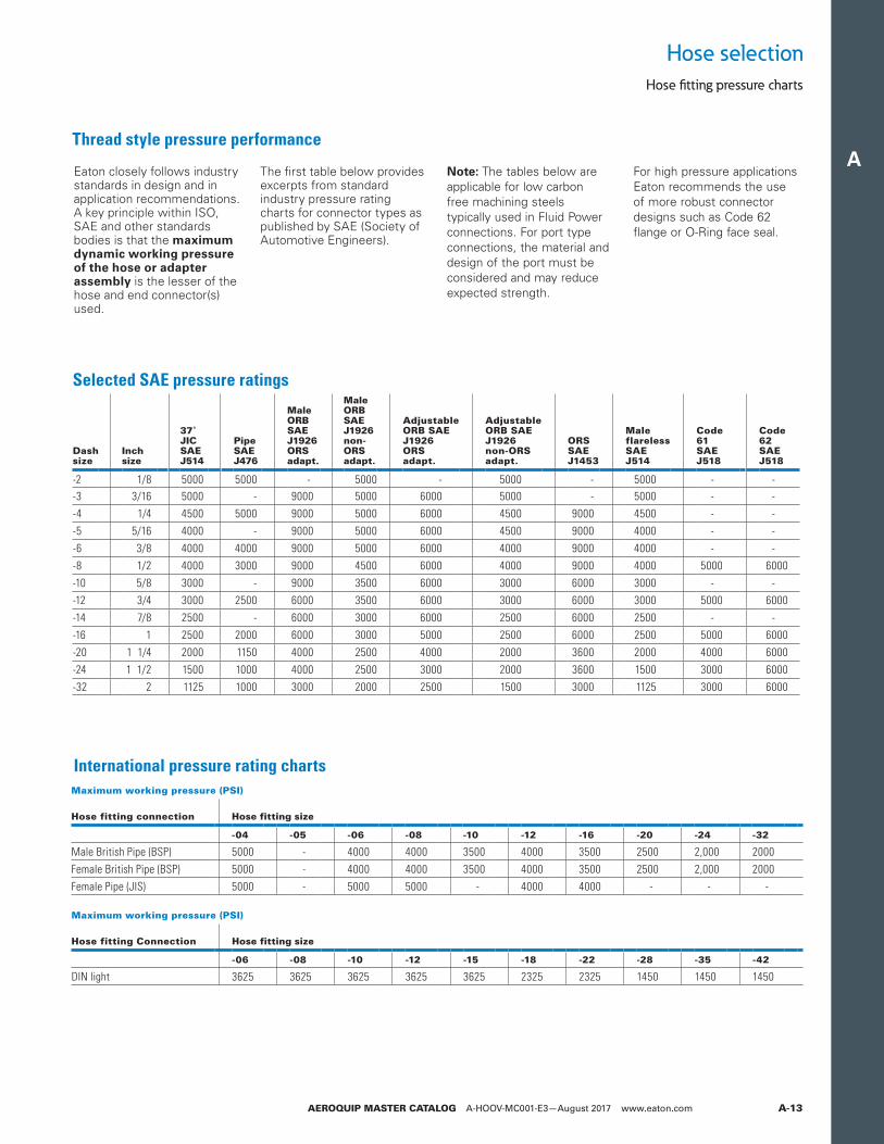
Thread style pressure performance
Selected SAE pressure ratings
Dashsize
Inchsize
37˚ JICSAE J514
PipeSAE J476
Male ORBSAE J1926ORS adapt.
Male ORBSAE J1926non-ORS adapt.
Adjustable ORB SAE J1926ORS adapt.
Adjustable ORB SAE J1926non-ORS adapt.
ORSSAE J1453
MaleflarelessSAE J514
Code 61SAE J518
Code62SAE J518
-2 1/8 5000 5000 - 5000 - 5000 - 5000 - --3 3/16 5000 - 9000 5000 6000 5000 - 5000 - --4 1/4 4500 5000 9000 5000 6000 4500 9000 4500 - --5 5/16 4000 - 9000 5000 6000 4500 9000 4000 - --6 3/8 4000 4000 9000 5000 6000 4000 9000 4000 - --8 1/2 4000 3000 9000 4500 6000 4000 9000 4000 5000 6000-10 5/8 3000 - 9000 3500 6000 3000 6000 3000 - --12 3/4 3000 2500 6000 3500 6000 3000 6000 3000 5000 6000-14 7/8 2500 - 6000 3000 6000 2500 6000 2500 - --16 1 2500 2000 6000 3000 5000 2500 6000 2500 5000 6000-20 1 1/4 2000 1150 4000 2500 4000 2000 3600 2000 4000 6000-24 1 1/2 1500 1000 4000 2500 3000 2000 3600 1500 3000 6000-32 2 1125 1000 3000 2000 2500 1500 3000 1125 3000 6000
Maximum working pressure (PSI)
Hose fitting connection Hose fitting size
-04 -05 -06 -08 -10 -12 -16 -20 -24 -32
Male British Pipe (BSP) 5000 - 4000 4000 3500 4000 3500 2500 2,000 2000Female British Pipe (BSP) 5000 - 4000 4000 3500 4000 3500 2500 2,000 2000Female Pipe (JIS) 5000 - 5000 5000 - 4000 4000 - - -
International pressure rating charts
Maximum working pressure (PSI)
Hose fitting Connection Hose fitting size
-06 -08 -10 -12 -15 -18 -22 -28 -35 -42
DIN light 3625 3625 3625 3625 3625 2325 2325 1450 1450 1450
Eaton closely follows industry standards in design and in application recommendations. A key principle within ISO, SAE and other standards bodies is that the maximum dynamic working pressure of the hose or adapter assembly is the lesser of the hose and end connector(s) used.
The first table below provides excerpts from standard industry pressure rating charts for connector types as published by SAE (Society of Automotive Engineers).
Note: The tables below are applicable for low carbon free machining steels typically used in Fluid Power connections. For port type connections, the material and design of the port must be considered and may reduce expected strength.
For high pressure applications Eaton recommends the use of more robust connector designs such as Code 62 flange or O-Ring face seal.
A
AEROQUIP MASTER CATALOG A-HOOV-MC001-E3—August 2017 www.eaton.comA-14
Hose selection
Hose fitting pressure charts
Hose fitting pressure charts
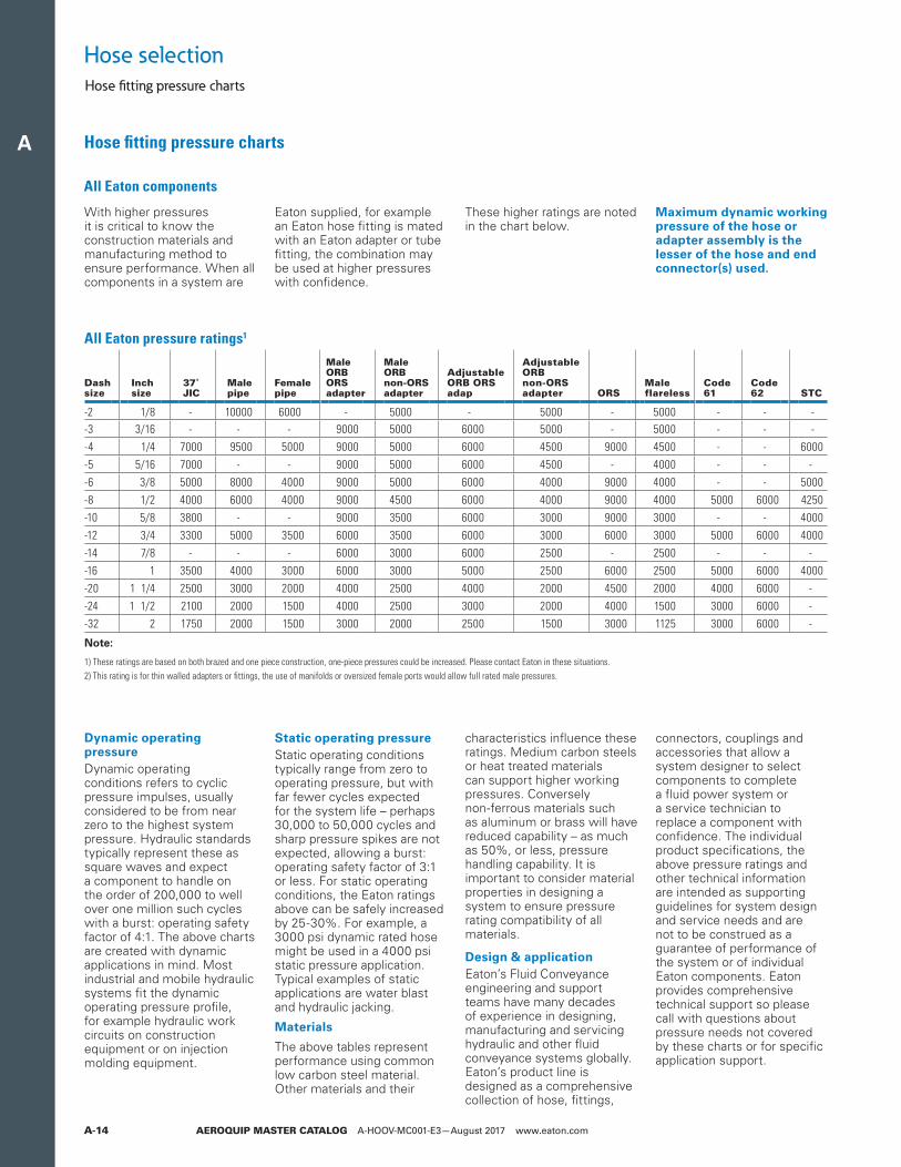
All Eaton components
With higher pressures it is critical to know the construction materials and manufacturing method to ensure performance. When all components in a system are
Eaton supplied, for example an Eaton hose fitting is mated with an Eaton adapter or tube fitting, the combination may be used at higher pressures with confidence.
These higher ratings are noted in the chart below.
Maximum dynamic working pressure of the hose or adapter assembly is the lesser of the hose and end connector(s) used.
Dynamic operating pressure Dynamic operating conditions refers to cyclic pressure impulses, usually considered to be from near zero to the highest system pressure. Hydraulic standards typically represent these as square waves and expect a component to handle on the order of 200,000 to well over one million such cycles with a burst: operating safety factor of 4:1. The above charts are created with dynamic applications in mind. Most industrial and mobile hydraulic systems fit the dynamic operating pressure profile, for example hydraulic work circuits on construction equipment or on injection molding equipment.
Static operating pressure Static operating conditions typically range from zero to operating pressure, but with far fewer cycles expected for the system life – perhaps 30,000 to 50,000 cycles and sharp pressure spikes are not expected, allowing a burst: operating safety factor of 3:1 or less. For static operating conditions, the Eaton ratings above can be safely increased by 25-30%. For example, a 3000 psi dynamic rated hose might be used in a 4000 psi static pressure application. Typical examples of static applications are water blast and hydraulic jacking.
Materials
The above tables represent performance using common low carbon steel material. Other materials and their
characteristics influence these ratings. Medium carbon steels or heat treated materials can support higher working pressures. Conversely non-ferrous materials such as aluminum or brass will have reduced capability – as much as 50%, or less, pressure handling capability. It is important to consider material properties in designing a system to ensure pressure rating compatibility of all materials.
Design & application Eaton’s Fluid Conveyance engineering and support teams have many decades of experience in designing, manufacturing and servicing hydraulic and other fluid conveyance systems globally. Eaton’s product line is designed as a comprehensive collection of hose, fittings,
connectors, couplings and accessories that allow a system designer to select components to complete a fluid power system or a service technician to replace a component with confidence. The individual product specifications, the above pressure ratings and other technical information are intended as supporting guidelines for system design and service needs and are not to be construed as a guarantee of performance of the system or of individual Eaton components. Eaton provides comprehensive technical support so please call with questions about pressure needs not covered by these charts or for specific application support.
All Eaton pressure ratings1
Dashsize
Inchsize
37˚ JIC
Malepipe
Femalepipe
Male ORBORS adapter
Male ORBnon-ORS adapter
Adjustable ORB ORS adap
Adjustable ORB non-ORS adapter ORS
Male flareless
Code 61
Code62 STC
-2 1/8 - 10000 6000 - 5000 - 5000 - 5000 - - --3 3/16 - - - 9000 5000 6000 5000 - 5000 - - --4 1/4 7000 9500 5000 9000 5000 6000 4500 9000 4500 - - 6000-5 5/16 7000 - - 9000 5000 6000 4500 - 4000 - - --6 3/8 5000 8000 4000 9000 5000 6000 4000 9000 4000 - - 5000-8 1/2 4000 6000 4000 9000 4500 6000 4000 9000 4000 5000 6000 4250-10 5/8 3800 - - 9000 3500 6000 3000 9000 3000 - - 4000-12 3/4 3300 5000 3500 6000 3500 6000 3000 6000 3000 5000 6000 4000-14 7/8 - - - 6000 3000 6000 2500 - 2500 - - --16 1 3500 4000 3000 6000 3000 5000 2500 6000 2500 5000 6000 4000-20 1 1/4 2500 3000 2000 4000 2500 4000 2000 4500 2000 4000 6000 --24 1 1/2 2100 2000 1500 4000 2500 3000 2000 4000 1500 3000 6000 --32 2 1750 2000 1500 3000 2000 2500 1500 3000 1125 3000 6000 -
ote:N
1) These ratings are based on both brazed and one piece construction, one-piece pressures could be increased. Please contact Eaton in these situations.2) This rating is for thin walled adapters or fittings, the use of manifolds or oversized female ports would allow full rated male pressures.
A
AEROQUIP MASTER CATALOG A-HOOV-MC001-E3—August 2017 www.eaton.com A-15
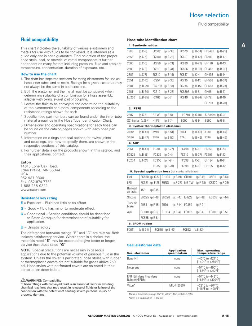
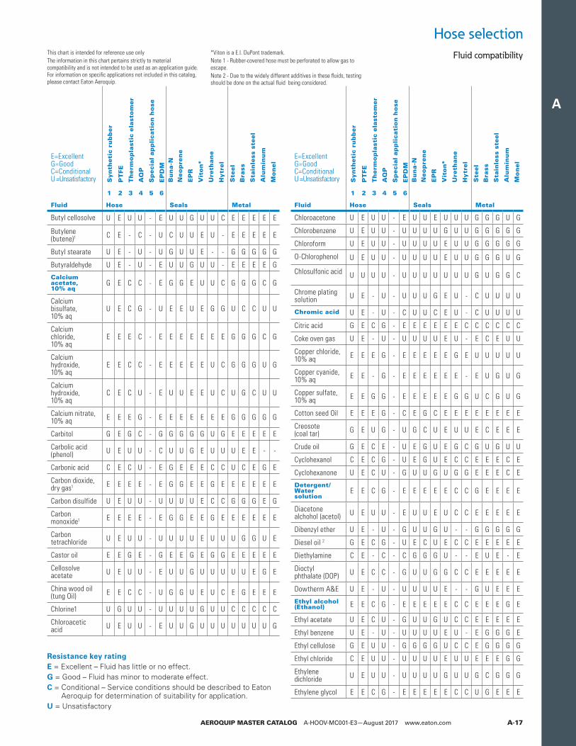
This chart indicates the suitability of various elastomers and metals for use with fluids to be conveyed. It is intended as a guide only and is not a guarantee. Final selection of the proper hose style, seal, or material of metal components is further dependent on many factors including pressure, fluid and ambient temperature, concentration, duration of exposure, etc.
How to use the chart1. The chart has separate sections for rating elastomers for use as
hose inner tubes and as seals. Ratings for a given elastomer may not always be the same in both sections.
2. Both the elastomer and the metal must be considered when determining suitability of a combination for a hose assembly, adapter with o-ring, swivel joint or coupling.
3. Locate the fluid to be conveyed and determine the suitability of the elastomeric and metal components according to the resistance ratings shown for each.
4. Specific hose part numbers can be found under the inner tube material groupings in the Hose Tube Identification Chart.
5. Dimensional and operating specifications for each hose can be found on the catalog pages shown with each hose part number.
6. Information on o-rings and seal options for swivel joints and couplings, and how to specify them, are shown in the respective sections of this catalog.
7. For further details on the products shown in this catalog, and their applications, contact:
Eaton 14615 Lone Oak Road, Eden Prairie, MN 55344 USA 952-937-9800 Fax: 952-974-7722 1-888-258-0222 www.eaton.com
Resistance key ratingE = Excellent – Fluid has little or no effect.
G = Good – Fluid has minor to moderate effect.
C = Conditional – Service conditions should be described to Eaton Aeroquip for determination of suitability for application.
U = Unsatisfactory
The differences between ratings “E” and “G” are relative. Both indicate satisfactory service. Where there is a choice, the materials rated “E” may be expected to give better or longer service than those rated “G”
NOTE: Special precautions are necessary in gaseous applications due to the potential volume of gaseous fluid in the system. Unless the cover is perforated, hose styles with rubber or thermoplastic covers are not suitable for gases above 250 psi. Hose styles with perforated covers are so noted in their construction descriptions.
WARNING: Compatibility of hose fittings with conveyed fluid is an essential factor in avoiding chemical reactions that may result in release of fluids or failure of the connection with the potential of causing severe personal injury or property damage.
Hose tube identification chart
1. Synthetic rubber
1503 (p.C-9) EC502 (p.B-33) FC579 (p.B-34) FC849B (p.B-25)
2556 (p.C-5) EC600 (p.B-20) FC619 (p.B-42) FC500 (p.B-17)
2565 (p.C-5) EC850 (p.B-21) FC639 (p.B-22) GH120 (p.B-13)
2580 (p.C-8) EC910 (p.B-41) FC606 (p.B-38) GH466 (p.B-39)
2583 (p.C-7) EC810 (p.B-19) FC647 (p.C-4) GH493 (p.B-14)
2651 (p.C-10) FC254 (p.B-36) FC735 (p.B-11) GH506 (p.B-37)
2681 (p.B-29) FC273B (p.B-18) FC736 (p.B-15) GH663 (p.B-23)
2781 (p.B-30) FC310 (p.B-26) FC839B (p.B-8) GH681 (p.B-7)
EC230 (p.B-35) FC466 (p.C-7) FC849 (p.B-24) GH781 (p.B-10)
GH793 (p.B-28)
2. PTFE
2807 (p.G-8) S-TW (p.G-5) FC740 (p.G-10) S-Series (p.G-3)
SC-Series (p.G-4) Hi-PSI (p.G-7) 8000 (p.G-9) 8500 (p.G-9)
3. Synflex thermoplastic elastomer
3E80 (p.B-48) 3VE0 (p.B-51) 30CT (p.B-49) 3130 (p.B-44)
3R80 (p.B-47) 3V10 (p.B-50) 37AL (p.B-46) 3740 (p.B-45)
4. AQP
2661 (p.B-43) FC300 (p.F-22) FC498 (p.C-6) FC650 (p.F-23)
EC525 (p.B-16) FC332 (p.C-4) FC510 (p.B-27) FC699 (p.F-23)
FC234 (p.F-24) FC350 (p.F-21) FC598 (p.C-6) GH194 (p.B-9)
FC355 (p.F-20) FC598 (p.C-6) GH195 (p.B-12)
5. Special application hose (not included in fluid chart)
Fuel FC650 (p. G-5) GH100 (p.F-19) GH101 (p.F-19) 35FH (p.F-13)
LPG FC321 (p. F-25) 35NG (p.F-27) NG-TW (p.F-28) CR170 (p.F-26)
Railroad air brake 1531 (p.F-15)
Silicone EH225 (p.F-16) EH226 (p. F-17) EH227 (p.F-18) EC038 (p.F-14)
Truck air brake 2554 (p.F-15) 2570 (p. F-14) FC350 (p.F-21)
A/C GH001 (p.E-3) GH134 (p.E-4) FC802 (p.E-4) FC800 (p.E-5)
FC555 (p.E-6)
Seal elastomer data
Seal elastomerApplication
specificationMax. operatingtemperature range
Buna-N† none –40°C to +121°C[–40°F to +250°F]
Neoprene none –54°C to +100°C[–65°F to +212°F]
EPR (Ethylene Propylene Rubber)/EPDM
none –54°C to +149°C[–65°F to +300°F]
Viton* MIL-R-25897 –29°C to +204°C[–15°F to +400°F]
†Buna-N temperature range -65°F to +225°F. Also per MIL-R-6855.*Viton is a trademark of E.I. DuPont.
Hose selection
Fluid compatibility
Fluid compatibility
6. EPDM rubber
FC611 (p.B-31) FC636 (p.B-40) FC693 (p.B-32)
A
AEROQUIP MASTER CATALOG A-HOOV-MC001-E3—August 2017 www.eaton.comA-16
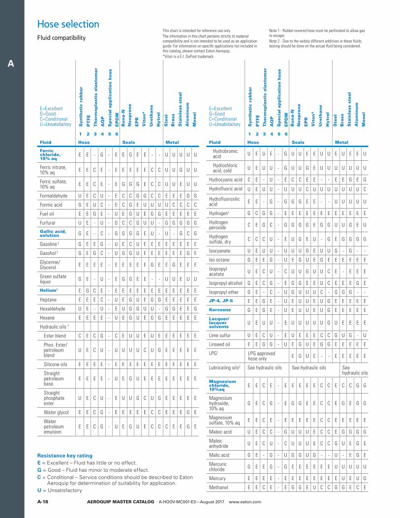
This chart is intended for reference use onlyThe information in this chart pertains strictly to material compatibility and is not intended to be used as an application guide. For information on specific applications not included in this catalog, please contact Eaton Aeroquip.
*Viton is a E.I. DuPont trademark.Note 1 - Rubber-covered hose must be perforated to allow gas to escape.Note 2 - Due to the widely different additives in these fluids, testing should be done on the actual fluid being considered.
Hose selectionFluid compatibility
Bu
na-N
Neo
pre
ne
EP
R
Vit
on*
Ure
than
e
Hytr
el
Bu
na-N
Neo
pre
ne
EP
R
Vit
on*
Ure
than
e
Hytr
el
Ste
el
Bra
ss
Sta
inle
ss s
teel
Alu
min
um
Mo
nel
Ste
el
Bra
ss
Sta
inle
ss s
teel
Alu
min
um
Mo
nel
Syn
theti
c ru
bb
er
PT
FE
Th
erm
op
last
ic e
last
om
er
AQ
P
Sp
ecia
l ap
pli
cati
on
ho
se
EP
DM
Syn
theti
c ru
bb
er
PT
FE
Th
erm
op
last
ic e
last
om
er
AQ
P
Sp
ecia
l ap
pli
cati
on
ho
se
EP
DM
E=ExcellentG=GoodC=ConditionalU =Unsatisfactory
1 2 3 4 5 6
Fluid Hose Seals Metal
Acetaldehyde U E C U - G U C C U U G G E E E E
Acetic acid, 10% U E C C - E U U E G U C U U C C U
Acetic acid, glacial U E C C - E U U C U U C U U C C C
Acetone U E G U - E U U G U U G E E E E E
Acetophenone U E - U - E U U E U U - E E E C E
Acetyl acetone U E U U - E U U G U U G U C C C C
Acetyl chloride U E U U - U U U U E U U C C C U E
Acetylene1 G E G G - E U U G E G G E E E E E
Air, hot (up to +160°F)1 E E E E - E E E E E E E E E E E E
Air, hot (161°F – 200°F)1 C E U E - E G G E E G G E E E E E
Air, hot (201°F – 300°F)1 U E U C - G U U G E U U E E E E E
Air wet, below 160°F1 E E C E - E E E E E G C U G E E E
Aluminum chloride, 10% aq E E E E - E E E E E G E U U U U U
Aluminum fluoride, 10% aq E E E U - E E E E E G E U U U E C
Aluminum nitrate, 10% aq E E E C - E E E E E G E U U C C C
Aluminum sulfate, 10% aq E E G E - E E E E E - G U C E C C
Alums, 10% aq E E E E - E E E E E E E U C E C C
Ammonia, anhydrous1 C U U C - E E E E U - - E U E E E
Ammonia, aqueous G G U C - E E E E U - - E U E E E
Ammonium carbonate, 10% aq
U E C U - E U E E U - C C U C C C
Ammonium chloride, 10% aq
E E C U - E E E E U - - U U C U C
Ammonium hydroxide, 10% aq
U E U U - E C C E C U U G U C C U
Ammonium nitrate, 10% aq E E C U - E E G E U G C G U G G U
E=ExcellentG=GoodC=ConditionalU =Unsatisfactory
1 2 3 4 5 6
Fluid Hose Seals Metal
Ammonium phosphate, 10% aq
E E C U - E E E E - G C U C G U G
Ammonium sulfate/sulfide, 10% aq
E E C U - E E E E U G C U U G U G
Amyl acetate U E U U - E U U G U U U E E E E E
Amyl alcohol G E E C - E G C E G C E G G E U G
Aniline, aniline oil
U E U U - E U U G U U U E U E G G
Aniline dyes U E U U - E U G G G U U U C G C G
Asphalt, < 200°F C E G G - U G C U E G G E G E C E
IRM 901 E E E E - U E E C E E E E E E E E
ASTM #2 E E E E - U E G U E G E E E E E E
IRM 903 E E E E - U E G U E G E E E E E E
Automatic trans. fluid 2
G E G G - U E G U E C G E E E E E
Barium chloride, 10% aq
E E C C - E E E E E G C U G G G G
Barium hydroxide, 105 aq
E E G C - E E E E E E G G U G U G
Barium sulfide, 10% aq
E E C C - E E E E E G C C U G U U
Benzene, benzol U E U U - U U U U E U C G E E G E
Benzoic acid U E C U - U U U E E C C U G G G G
Benzyl alcohol U E C U - E U G G E C C E G E G G
Biodiesel (<180˚F)
G E G C - U
Biodiesel (>180˚F)
C E U U - U
Black sulfate liquor
G E C C - E C C C E U C E C E U U
Blast furnace gas
C U C G - U U U U E U C E C E U U
Borax, 10% aq E E G C - E G G E E G E E E E G -
Boric acid, 10% aq
E E C E - E G G G E G G U G C C C
Brine G E C C - C E G E E G C U G G U E
Bromine, dry U E U U - U U U U E U U U C U C C
Butane1 LPG approvedhose only
- E C U E - - E E E E E
Butyl acetate U E U U - E U U G U U C E E E E E
Butyl alcohol E E G G - C E E G E G G G G G G G
Resistance key ratingE = Excellent – Fluid has little or no effect.G = Good – Fluid has minor to moderate effect.C = Conditional – Service conditions should be described to Eaton
Aeroquip for determination of suitability for application.U = Unsatisfactory
A
AEROQUIP MASTER CATALOG A-HOOV-MC001-E3—August 2017 www.eaton.com A-17
This chart is intended for reference use onlyThe information in this chart pertains strictly to material compatibility and is not intended to be used as an application guide. For information on specific applications not included in this catalog, please contact Eaton Aeroquip.
*Viton is a E.I. DuPont trademark.Note 1 - Rubber-covered hose must be perforated to allow gas to escape.Note 2 - Due to the widely different additives in these fluids, testing should be done on the actual fluid being considered.
Hose selectionFluid compatibility
Bu
na-N
Neo
pre
ne
EP
R
Vit
on*
Ure
than
e
Hytr
el
Bu
na-N
Neo
pre
ne
EP
R
Vit
on*
Ure
than
e
Hytr
el
Ste
el
Bra
ss
Sta
inle
ss s
teel
Alu
min
um
Mo
nel
Ste
el
Bra
ss
Sta
inle
ss s
teel
Alu
min
um
Mo
nel
Syn
theti
c ru
bb
er
PT
FE
Th
erm
op
last
ic e
last
om
er
AQ
P
Sp
ecia
l ap
pli
cati
on
ho
se
EP
DM
Syn
theti
c ru
bb
er
PT
FE
Th
erm
op
last
ic e
last
om
er
AQ
P
Sp
ecia
l ap
pli
cati
on
ho
se
EP
DM
E=ExcellentG=GoodC=ConditionalU =Unsatisfactory
1 2 3 4 5 6
Fluid Hose Seals Metal
Butyl cellosolve U E U U - E U U G U U C E E E E E
Butylene (butene)1 C E - C - U C U U E U - E E E E E
Butyl stearate U E - U - U G U U E - - G G G G G
Butyraldehyde U E - U - E U U G U U - E E E E G
Calcium acetate, 10% aq
G E C C - E G G E U U C G G G C G
Calcium bisulfate, 10% aq
U E C G - U E E U E G G U C C U U
Calcium chloride, 10% aq
E E E C - E E E E E E E G G G C G
Calcium hydroxide, 10% aq
E E C C - E E E E E U C G G G U G
Calcium hydroxide, 10% aq
C E C U - E U U E E U C U G C U U
Calcium nitrate, 10% aq E E E G - E E E E E E E G G G G G
Carbitol G E G C - G G G G G U G E E E E E
Carbolic acid (phenol) U E U U - C U U G E U U U E E - -
Carbonic acid C E C U - E G E E E C C U C E G E
Carbon dioxide, dry gas1 E E E E - E G G E E G E E E E E E
Carbon disulfide U E U U - U U U U E C C G G G E G
Carbon monoxide1 E E E E - E G G E E G E E E E E E
Carbon tetrachloride U E U U - U U U U E U U U G G U E
Castor oil E E G E - G E E G E G G E E E E E
Cellosolve acetate U E U U - E U U G U U U U U E G E
China wood oil (tung Oil) E E C C - U G G U E U C E G E E E
Chlorine1 U G U U - U U U U G U U C C C C C
Chloroacetic acid U E U U - E U U G U U U U U U U G
E=ExcellentG=GoodC=ConditionalU =Unsatisfactory
1 2 3 4 5 6
Fluid Hose Seals Metal
Chloroacetone U E U U - E U U E U U U G G G U G
Chlorobenzene U E U U - U U U U G U U G G G G G
Chloroform U E U U - U U U U E U U G G G G G
O-Chlorophenol U E U U - U U U U E U U G G G U G
Chlosulfonic acid U U U U - U U U U U U U G U G G C
Chrome plating solution U E - U - U U U G E U - C U U U U
Chromic acid U E - U - C U U C E U - C U U U U
Citric acid G E C G - E E E E E E C C C C C C
Coke oven gas U E - U - U U U U E U - E C E U U
Copper chloride, 10% aq E E E G - E E E E E G E U U U U U
Copper cyanide, 10% aq E E - G - E E E E E E - E U G U G
Copper sulfate, 10% aq E E G G - E E E E E G G U C G U G
Cotton seed Oil E E E G - C E G C E E E E E E E E
Creosote (coal tar) G E U G - U G C U E U U E C E E E
Crude oil G E C E - U E G U E G C G U G U U
Cyclohexanol C E C G - U E G U E C C E E E C E
Cyclohexanone U E C U - G U U G U G G E E E C E
Detergent/Water solution
E E C G - E E E E E C C G E E E E
Diacetone alchohol (acetol) U E U U - E U U E U C C E E E E E
Dibenzyl ether U E - U - G U U G U - - G G G G G
Diesel oil 2 G E C G - U E C U E C C E E E E E
Diethylamine C E - C - C G G G U - - E U E - E
Dioctyl phthalate (DOP) U E C C - G U U G G C C E E E E E
Dowtherm A&E U E - U - U U U U E - - G U E E E
Ethyl alcohol (Ethanol) E E C G - E E E E E C C E E E G E
Ethyl acetate U E C U - G U U G U C C E E E E E
Ethyl benzene U E - U - U U U U E U - E G G G E
Ethyl cellulose G E U U - G G G G U C C E G G G G
Ethyl chloride C E U U - U U U U E U U E E E G G
Ethylene dichloride U E U U - U U U U G U U G C G G G
Ethylene glycol E E C G - E E E E E C C U G E E E
Resistance key ratingE = Excellent – Fluid has little or no effect.G = Good – Fluid has minor to moderate effect.C = Conditional – Service conditions should be described to Eaton
Aeroquip for determination of suitability for application.U = Unsatisfactory
A
AEROQUIP MASTER CATALOG A-HOOV-MC001-E3—August 2017 www.eaton.comA-18
This chart is intended for reference use onlyThe information in this chart pertains strictly to material compatibility and is not intended to be used as an application guide. For information on specific applications not included in this catalog, please contact Eaton Aeroquip.*Viton is a E.I. DuPont trademark.
Note 1 - Rubber-covered hose must be perforated to allow gas to escape.Note 2 - Due to the widely different additives in these fluids, testing should be done on the actual fluid being considered.
Hose selectionFluid compatibility
Bu
na-N
Neo
pre
ne
EP
R
Vit
on*
Ure
than
e
Hytr
el
Bu
na-N
Neo
pre
ne
EP
R
Vit
on*
Ure
than
e
Hytr
el
Ste
el
Bra
ss
Sta
inle
ss s
teel
Alu
min
um
Mo
nel
Ste
el
Bra
ss
Sta
inle
ss s
teel
Alu
min
um
Mo
nel
Syn
theti
c ru
bb
er
PT
FE
Th
erm
op
last
ic e
last
om
er
AQ
P
Sp
ecia
l ap
pli
cati
on
ho
se
EP
DM
Syn
theti
c ru
bb
er
PT
FE
Th
erm
op
last
ic e
last
om
er
AQ
P
Sp
ecia
l ap
pli
cati
on
ho
se
EP
DM
E=ExcellentG=GoodC=ConditionalU =Unsatisfactory
1 2 3 4 5 6
Fluid Hose Seals Metal
Ferric chloride, 10% aq
E E - G - E E G E E - - U U U U U
Ferric nitrate, 10% aq E E C E - E E E E E C C U U G U U
Ferric sulfate, 10% aq E E C E - E G G G E C C U U E U U
Formaldehyde U E C U - E C C G G C C E E E G G
Formic acid G E U C - E C G E U U U U C C C C
Fuel oil E E G E - U E G U E G G E E E E E
Furfural U E - U - G C C G U U - G G G G G
Gallic acid, solution G E - C - G G G G E U - U - G C G
Gasoline 2 G E E G - U E C U E E E E E E E E
Gasohol 2 G E G C - U G G U E E E E E E G E
Glycerine/Glycerol E E E E - E E E E E G E E G E E E
Green sulfate liquor G E - U - E G G E E - - U U E U U
Helium1 E G C E - E E E E E E E E E E E E
Heptane E E E C - U E G U E G G E E E E E
Hexaldehyde U E - U - E U G G U U - G G E E G
Hexane E E E E - U E G U E G G E E E E E
Hydraulic oils 2
Ester blend C E C G - C E U U E U E E E E E E
Phos. Ester/petroleum blend
U E C U - U U U U C U G E E E E E
Silicone oils E E E E - E E E E E E E E E E E E
Straight petroleum base
E E E E - U E G U E E E E E E E E
Straight phosphate ester
U E C U - E U U G C U G E E E E E
Water glycol E E C G - E E E E E C C E E E G E
Water petroleum emulsion
E E C G - U E G U E C C C E E G E
E=ExcellentG=GoodC=ConditionalU =Unsatisfactory
1 2 3 4 5 6
Fluid Hose Seals Metal
Hydrobromic acid U E U E - G U U E E U U E U E E U
Hydrochloric acid, cold U E U U - G U U G E U U U U U U U
Hydrocyanic acid C E - U - E C C E E - - E E G E G
Hydrofluoric acid U E U U - U U U C U U U U U U U C
Hydrofluorosilic acid E E - G - G G G E E - - U U U U U
Hydrogen1 G C G G - E E E E E E E E E E E E
Hydrogen peroxide C E G C - G G G G E G G U U G E U
Hydrogen sulfide, dry C C C U - E U G E U - G E G G G G
Isocyanate U E U U - U U U G E U U G - G - -
Iso octane G E E G - U E G U E G E E E E E E
Isopropyl acetate U E C U - C U U G U U C E - E E E
Isopropyl alcohol G E C G - E G G E E U C E E E G E
Isopropyl ether G E - C - U G U U U C - G G G - -
JP-4, JP-5 E E G E - U E U U E U G E E E E E
Kerosene G E G E - U E U U E U G E E E E E
Lacquer/lacquer solvents
U E U U - E U U U U U G U E E E E
Lime sulfur U E C U - E U E E E C C G U G - U
Linseed oil E E G G - U E G U E G G E E E E E
LPG1 LPG approvedhose only E G U E - - E E E E E
Lubricating oils2 See hydraulic oils See hydraulic oils See hydraulic oils
Magnesium chloride, 10%aq
E E C E - E E E E E C C E C C G G
Magnesium hydroxide, 10% aq
G E C G - E G G E E C C E G E G G
Magnesium sulfate, 10% aq E E C E - E E E E E C C E E E E E
Maleic acid U E C C - G U U U E C C E G G G G
Maleic anhydride U E C U - C U U U E C C G U E G E
Malic acid G E - G - U G G U G - - U - E G E
Mercuric chloride G E E G - G E E E E E E U U U U U
Mercury E E E E - E E E E E E E E U E U G
Methanol E E C E - E G G E U C C G G E C E
Resistance key ratingE = Excellent – Fluid has little or no effect.G = Good – Fluid has minor to moderate effect.C = Conditional – Service conditions should be described to Eaton
Aeroquip for determination of suitability for application.U = Unsatisfactory
A
AEROQUIP MASTER CATALOG A-HOOV-MC001-E3—August 2017 www.eaton.com A-19
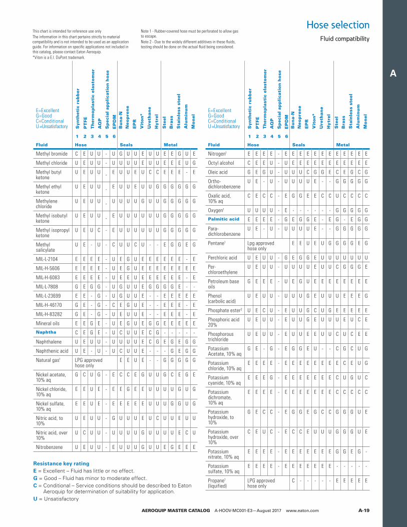
This chart is intended for reference use onlyThe information in this chart pertains strictly to material compatibility and is not intended to be used as an application guide. For information on specific applications not included in this catalog, please contact Eaton Aeroquip.*Viton is a E.I. DuPont trademark.
Note 1 - Rubber-covered hose must be perforated to allow gas to escape.Note 2 - Due to the widely different additives in these fluids, testing should be done on the actual fluid being considered.
Hose selectionFluid compatibility
Bu
na-N
Neo
pre
ne
EP
R
Vit
on*
Ure
than
e
Hytr
el
Bu
na-N
Neo
pre
ne
EP
R
Vit
on*
Ure
than
e
Hytr
el
Ste
el
Bra
ss
Sta
inle
ss s
teel
Alu
min
um
Mo
nel
Ste
el
Bra
ss
Sta
inle
ss s
teel
Alu
min
um
Mo
nel
Syn
theti
c ru
bb
er
PT
FE
Th
erm
op
last
ic e
last
om
er
AQ
P
Sp
ecia
l ap
pli
cati
on
ho
se
EP
DM
Syn
theti
c ru
bb
er
PT
FE
Th
erm
op
last
ic e
last
om
er
AQ
P
Sp
ecia
l ap
pli
cati
on
ho
se
EP
DM
E=ExcellentG=GoodC=ConditionalU =Unsatisfactory
1 2 3 4 5 6
Fluid Hose Seals Metal
Methyl bromide C E U U - U G U U E U U E E G U E
Methyl chloride U E U U - U U U U E U U E E E U G
Methyl butyl ketone
U E U U - E U U E U C C E E E - E
Methyl ethyl ketone
U E U U - E U U E U U G G G G G G
Methylene chloride
U E U U - U U U U G U U G G G G G
Methyl isobutyl ketone
U E U U - E U U U U U U G G G G G
Methyl isopropyl ketone
U E U C - E U U U U U U G G G G G
Methyl salicylate
U E - U - C U U C U - - E G G E G
MIL-L-2104 E E E E - U E G U E E E E E E - E
MIL-H-5606 E E E E - U E G U E E E E E E E E
MIL-H-6083 E E E E - U E E U E E E E E E - E
MIL-L-7808 G E G G - U G U U E G G G G E - -
MIL-L-23699 E E - G - U G U U E - - E E E E E
MIL-H-46170 G E - G - C E G U E - - E E E - E
MIL-H-83282 G E - G - U E U U E - - E E E - E
Mineral oils E E G E - U E G U E G G E E E E E
Naphtha C E G E - U C U U E C G - - - - -
Naphthalene U E U U - U U U U E C G E G E G G
Naphthenic acid U E - U - U C U U E - - - G E G G
Natural gas1 LPG approvedhose only
E E U E - - G G G G G
Nickel acetate, 10% aq
G C U G - E C C E G U U G C E G E
Nickel chloride, 10% aq
E E U E - E E G E E U U U U G U G
Nickel sulfate, 10% aq
E E U E - E E E E E U U U G G U G
Nitric acid, to 10%
U E U U - G U U U E U C U U E U U
Nitric acid, over 10%
U C U U - U U U U G U U U U E C U
Nitrobenzene U E U U - E U U U G U U E G E E E
E=ExcellentG=GoodC=ConditionalU =Unsatisfactory
1 2 3 4 5 6
Fluid Hose Seals Metal
Nitrogen1 E E E E - E E E E E E E E E E E E
Octyl alcohol C E E U - U E E E E E E E E E E E
Oleic acid G E G U - U U U C G G E C E G C G
Ortho-dichlorobenzene
U E - U - U U U U E - - G G G G G
Oxalic acid, 10% aq
C E C C - E G G E E C C U C C C C
Oxygen1 U U U U - E - - - - - - G G G G G
Palmitic acid E E E E - G E G G E - E G - E G G
Para-dichlorobenzene
U E - U - U U U U E - - G G G G G
Pentane1 Lpg approvedhose only
E E U E U G G G G E G
Perchloric acid U E U U - G E G G E U U U U U U U
Per- chloroethylene
U E U U - U U U U E U U C G G G E
Petroleum base oils
G E E E - U E G U E E E E E E E E
Phenol (carbolic acid)
U E U U - U U U G E U U U E E E G
Phosphate ester2 U E C U - E U U G C U G E E E E E
Phosphoric acid 20%
U E U U - E U U G E U U U E U C E
Phosphorous trichloride
U E U U - E U U E E U U C U C E E
Potassium Acetate, 10% aq
G E - G - E G G E U - - C G C U G
Potassium chloride, 10% aq
E E E E - E E E E E E E E C E U G
Potassium cyanide, 10% aq
E E E G - E E E E E E E C U G U C
Potassium dichromate, 10% aq
E E E E - E E E E E E E C C C C C
Potassium hydroxide, to 10%
G E C C - E G G E G C C G G G U E
Potassium hydroxide, over 10%
C E U C - E C C E U U U G G G U E
Potassium nitrate, 10% aq
E E E E - E E E E E E E G G E G -
Potassium sulfate, 10% aq
E E E E - E E E E E E E - - - - -
Propane1 (liquified)
LPG approvedhose only
C - - - - - E E E E E
Resistance key ratingE = Excellent – Fluid has little or no effect.G = Good – Fluid has minor to moderate effect.C = Conditional – Service conditions should be described to Eaton
Aeroquip for determination of suitability for application.U = Unsatisfactory
A
AEROQUIP MASTER CATALOG A-HOOV-MC001-E3—August 2017 www.eaton.comA-20
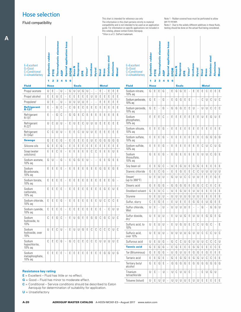
This chart is intended for reference use onlyThe information in this chart pertains strictly to material compatibility and is not intended to be used as an application guide. For information on specific applications not included in this catalog, please contact Eaton Aeroquip.*Viton is a E.I. DuPont trademark.
Note 1 - Rubber-covered hose must be perforated to allow gas to escape.Note 2 - Due to the widely different additives in these fluids, testing should be done on the actual fluid being considered.
Hose selectionFluid compatibility
Bu
na-N
Neo
pre
ne
EP
R
Vit
on*
Ure
than
e
Hytr
el
Bu
na-N
Neo
pre
ne
EP
R
Vit
on*
Ure
than
e
Hytr
el
Ste
el
Bra
ss
Sta
inle
ss s
teel
Alu
min
um
Mo
nel
Ste
el
Bra
ss
Sta
inle
ss s
teel
Alu
min
um
Mo
nel
Syn
theti
c ru
bb
er
PT
FE
Th
erm
op
last
ic e
last
om
er
AQ
P
Sp
ecia
l ap
pli
cati
on
ho
se
EP
DM
Syn
theti
c ru
bb
er
PT
FE
Th
erm
op
last
ic e
last
om
er
AQ
P
Sp
ecia
l ap
pli
cati
on
ho
se
EP
DM
E=ExcellentG=GoodC=ConditionalU =Unsatisfactory
1 2 3 4 5 6
Fluid Hose Seals Metal
Propyl acetate U E - U - G U U G U - - E - E E E
Propyl alcohol E E U E - E E E E E U U E E E E E
Propylene1 U E - U - U U U U E - - E E E E E
Refrigerant R-121
E - G C - C G E C E E E E E E E E
Refrigerant R-131
E - G C - G G E C E E E E E E E E
Refrigerant R-221
U C U U - E U E C U U U E E E E E
Refrigerant R-134a1
C C U U - E E C U U U E E E E E E
Sewage G E E G - E E E E E U E G G G G G
Silicone oils G E E G - E E E E E E E E E E E E
Soap (water solutions)
E E C E - E E E E E C C E E E U E
Sodium acetate, 10% aq
G U - G - E G G E U - - E E G E E
Sodium Bicarbonate, 10% aq
E E E E - E E E E E E E G G E G E
Sodium borate, 10% aq
E E E E - E E E E E E E E E E G -
Sodium carbonate, 10% aq
E E E E - E E E E E E E E G E U E
Sodium chloride, 10% aq
E E E G - E E E E E E E U C C C E
Sodium cyanide, 10% aq
E E E E - E E E E E E E E - C U U
Sodium hydroxide, to 10%
C E G C - E U G E E G G C G C U C
Sodium hydroxide, over 10%
U E C U - E U U G E C C C C C U C
Sodium hypochlorite, 10% aq
C E C G - G C C E C C C U U U U C
Sodium metaphosphate, 10% aq
E E E E - E E E E E E E E G G U G
E=ExcellentG=GoodC=ConditionalU =Unsatisfactory
1 2 3 4 5 6
Fluid Hose Seals Metal
Sodium nitrate, 10% aq
G E E G - E G G E - E E E C E E E
Sodium perborate, 10% aq
G E - G - E G G E E - - C U C U C
Sodium peroxide, 10% aq
G E - G - G G G E E U - U U C C C
Sodium phosphates, 10% aq
E E E C - E E E E E E E U E G U E
Sodium silicate, 10% aq
E E E G - E E E E E E E E E E E E
Sodium sulfate, 10% aq
E E E G - E E E E E E E C G G G G
Sodium sulfide, 10% aq
E E E G - E E E E E E E C U C U G
Sodium thiosulfate, 10% aq
G E E G - E G E E E E E U U C G E
Soy bean oil E E G C - U E G U E G G E E E E E
Stannic chloride G E C G - E E G E E C C U U U U U
Steam1 (up to 388°F)
U E U U - G U U C C U U E E E G E
Stearic acid G E G G - G G G G E G G C C E C E
Stoddard solvent G E U C - U E G U E U U E E E E E
Styrene U E U U - U U U U G U U E E E E E
Sulfur, slurry C E G E - E U E E E G G E U G E E
Sulfur chloride, Wet
U E - U - U U U U E - - G - G G U
Sulfur dioxide, dry1
U E U U - E U U G E U U E G G E G
Sulfuric acid, to 10%
U E U U - E U G U E C C U G C - E
Sulfuric acid, over 10%
U E U U - U U U U G U U C C C U C
Sulfurous acid U E U G - G C C U G U U U C C C U
Tannic acid G E G G - E G E E E G G E E E C E
Tar (Bituminous) G E G G - U G U U E G G E G E E E
Tartaric acid E E G E - G E G G E G G U C C E E
Tertiary butyl alcohol
G E G E - G G G G E G G G G G G G
Titanium tetrachloride
U E - U - U C U U E - - E U G U
Toluene (toluol) U E U U - U U U U E U U E E E E E
Resistance key ratingE = Excellent – Fluid has little or no effect.G = Good – Fluid has minor to moderate effect.C = Conditional – Service conditions should be described to Eaton
Aeroquip for determination of suitability for application.U = Unsatisfactory
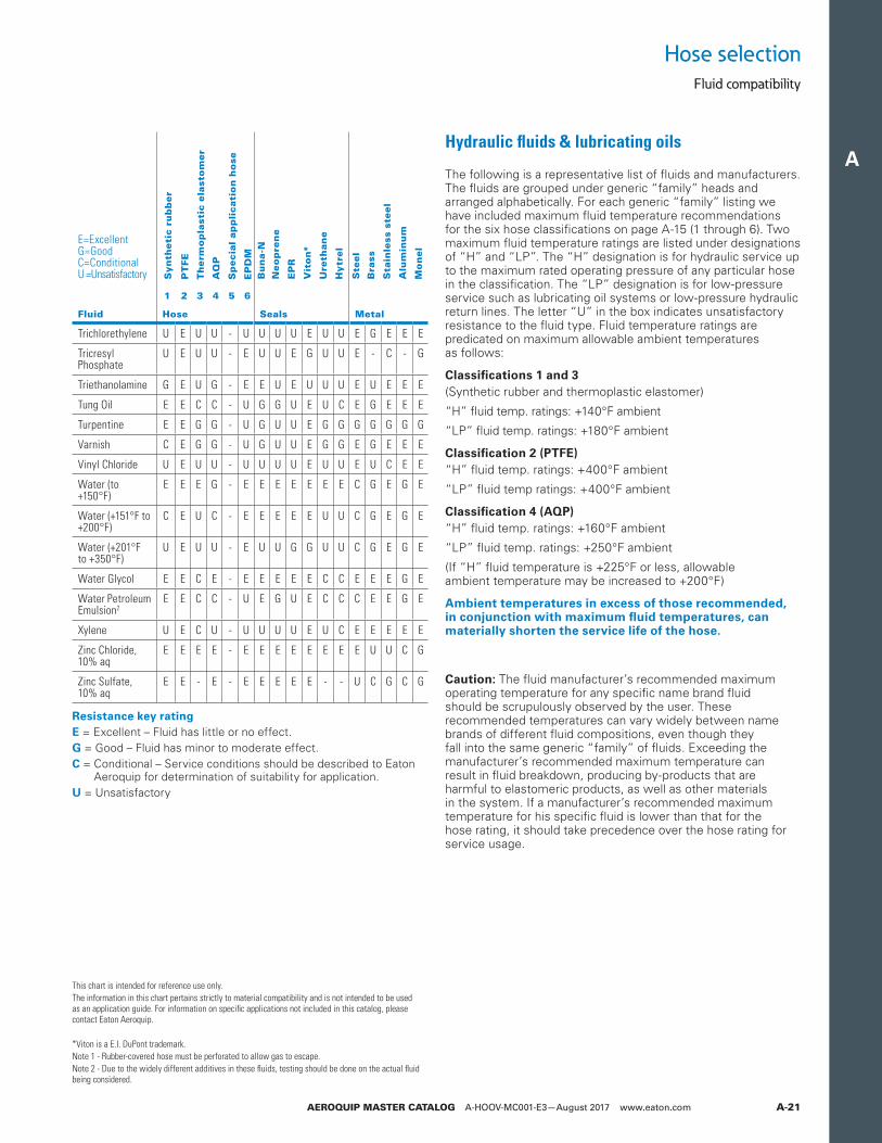
A
AEROQUIP MASTER CATALOG A-HOOV-MC001-E3—August 2017 www.eaton.com A-21
Hose selectionFluid compatibility
Caution: The fluid manufacturer’s recommended maximum operating temperature for any specific name brand fluid should be scrupulously observed by the user. These recommended temperatures can vary widely between name brands of different fluid compositions, even though they fall into the same generic “family” of fluids. Exceeding the manufacturer’s recommended maximum temperature can result in fluid breakdown, producing by-products that are harmful to elastomeric products, as well as other materials in the system. If a manufacturer’s recommended maximum temperature for his specific fluid is lower than that for the hose rating, it should take precedence over the hose rating for service usage.
Hydraulic fluids & lubricating oils
The following is a representative list of fluids and manufacturers. The fluids are grouped under generic “family” heads and arranged alphabetically. For each generic “family” listing we have included maximum fluid temperature recommendations for the six hose classifications on page A-15 (1 through 6). Two maximum fluid temperature ratings are listed under designations of “H” and “LP”. The “H” designation is for hydraulic service up to the maximum rated operating pressure of any particular hose in the classification. The “LP” designation is for low-pressure service such as lubricating oil systems or low-pressure hydraulic return lines. The letter “U” in the box indicates unsatisfactory resistance to the fluid type. Fluid temperature ratings are predicated on maximum allowable ambient temperatures as follows:
Classifications 1 and 3(Synthetic rubber and thermoplastic elastomer)
“H” fluid temp. ratings: +140°F ambient
“LP” fluid temp. ratings: +180°F ambient
Classification 2 (PTFE)“H” fluid temp. ratings: +400°F ambient
“LP” fluid temp ratings: +400°F ambient
Classification 4 (AQP)“H” fluid temp. ratings: +160°F ambient
“LP” fluid temp. ratings: +250°F ambient
(If “H” fluid temperature is +225°F or less, allowable ambient temperature may be increased to +200°F)
Ambient temperatures in excess of those recommended, in conjunction with maximum fluid temperatures, can materially shorten the service life of the hose.
Bu
na-N
Neo
pre
ne
EP
R
Vit
on*
Ure
than
e
Hytr
el
Ste
el
Bra
ss
Sta
inle
ss s
teel
Alu
min
um
Mo
nel
Syn
theti
c ru
bb
er
PT
FE
Th
erm
op
last
ic e
last
om
er
AQ
P
Sp
ecia
l ap
pli
cati
on
ho
se
EP
DM
E=ExcellentG=GoodC=ConditionalU =Unsatisfactory
1 2 3 4 5 6
Fluid Hose Seals Metal
Trichlorethylene U E U U - U U U U E U U E G E E E
Tricresyl Phosphate
U E U U - E U U E G U U E - C - G
Triethanolamine G E U G - E E U E U U U E U E E E
Tung Oil E E C C - U G G U E U C E G E E E
Turpentine E E G G - U G U U E G G G G G G G
Varnish C E G G - U G U U E G G E G E E E
Vinyl Chloride U E U U - U U U U E U U E U C E E
Water (to +150°F)
E E E G - E E E E E E E C G E G E
Water (+151°F to +200°F)
C E U C - E E E E E U U C G E G E
Water (+201°F to +350°F)
U E U U - E U U G G U U C G E G E
Water Glycol E E C E - E E E E E C C E E E G E
Water Petroleum Emulsion2
E E C C - U E G U E C C C E E G E
Xylene U E C U - U U U U E U C E E E E E
Zinc Chloride, 10% aq
E E E E - E E E E E E E E U U C G
Zinc Sulfate, 10% aq
E E - E - E E E E E - - U C G C G
This chart is intended for reference use only.The information in this chart pertains strictly to material compatibility and is not intended to be used as an application guide. For information on specific applications not included in this catalog, please contact Eaton Aeroquip.
*Viton is a E.I. DuPont trademark.Note 1 - Rubber-covered hose must be perforated to allow gas to escape.Note 2 - Due to the widely different additives in these fluids, testing should be done on the actual fluid being considered.
Resistance key ratingE = Excellent – Fluid has little or no effect.G = Good – Fluid has minor to moderate effect.C = Conditional – Service conditions should be described to Eaton
Aeroquip for determination of suitability for application.U = Unsatisfactory
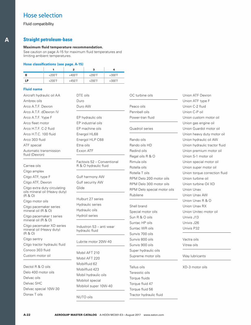
A
AEROQUIP MASTER CATALOG A-HOOV-MC001-E3—August 2017 www.eaton.comA-22
Hose selectionFluid compatibility
Straight petroleum-baseMaximum fluid temperature recommendation. See caution on page A-15 for maximum fluid temperatures and limiting ambient temperatures.
Hose classifications (see page. A-15)
1 2 3 4
H +200˚F +400˚F +200˚F +300˚F
LP +200˚F +450˚F +200˚F +300˚F
Aircraft hydraulic oil AA
Ambrex oils
Arco A.T.F. Dexron
Arco A.T.F. dDexron IV
Arco A.T.F. Yype F
Arco fleet motor
Arco H.T.F. C-2 fluid
Arco H.T.C. 100 fluid
Arco 303 fluid
ATF special
Automatic transmission fluid (Dexron)
Carnea oils
Citgo amplex
Citgo ATF, type F
Citgo ATF, Dexron
Citgo extra duty circulating oils mineral oil (Heavy duty)(R & O)
Citgo motor oils
Citgo pacemaker series mineral oil (R & O)
Citgo pacemaker t series mineral oil (R & O)
Citgo pacemaker XD series mineral oil (Heavy duty) (R & O)
Citgo sentry
Citgo tractor hydraulic fluid
Conoco 303 fluid
Custom motor oil
Dectol R & O oils
Delo 400 motor oils
Delvac oils
Delvac SHC
Delvac special 10W-30
Donax T oils
DTE oils
Duro
Duro AW
EP hydraulic oils
EP industrial oils
EP machine oils
Energol HL68
Energol HLP C68
Etna oils
Exxon ATF
Factovis 52 – Conventional R & O hydraulic fluid
Gulf harmony AW
Gulf security AW
Glide
Hulburt 27 series
Hydraulic series
Hydraulic oils
Hydroil series
Industron 53 – anti wear hydraulic fluid
Lubrite motor 20W-40
Mobil AFT 210
Mobil AFT 220
Mobilfluid 62
Mobilfluid 423
Mobil hydraulic oils
Mobiloil special
Mobiloil super 10W-40
NUTO oils
OC turbine oils
Peaco oils
Pennbell oils
Power-tran fluid
Quadroil series
Rando oils
Rando oils HD
Redind oils
Regal oils R & O
Rimula oils
Rotella oils
Rotella T oils
RPM Delo 200 motor oils
RPM Delo 300 motor oils
RPM Delo special motor oils
Rubilene
Shell brand
Special motor oils
Sun R & O oils
Suntac HP oils
Suntac WR oils
Sunvis 700 oils
Sunvis 800 oils
Sunvis 900 oils
Super hydraulic oils
Supreme motor oils
Tellus oils
Teresstic oils
Torque fluids
Torque fluid 47
Torque fluid 56
Tractor hydraulic fluid
Union ATF Dexron
Union ATF type F
Union C-2 fluid
Union C-P oil
Union custom motor oil
Union gas engine oil
Union Guardol motor oil
Union heavy duty motor oil
Union hydraulic oil AW
Union hydraulic tractor fluid
Union premium motor oil
Union S-1 motor oil
Union special motor oil
Union super motor oil
Union torque correction fluid
Union turbine oil
Union turbine Oil XD
Union Unax
Union Unax AW
Union Unax R & O
Union Unax RX
Union Unitec motor oil
Univis J13
Univis J26
Univis P32
Vactra oils
Vitrea oils
Way lubricants
XD-3 motor oils
Fluid name
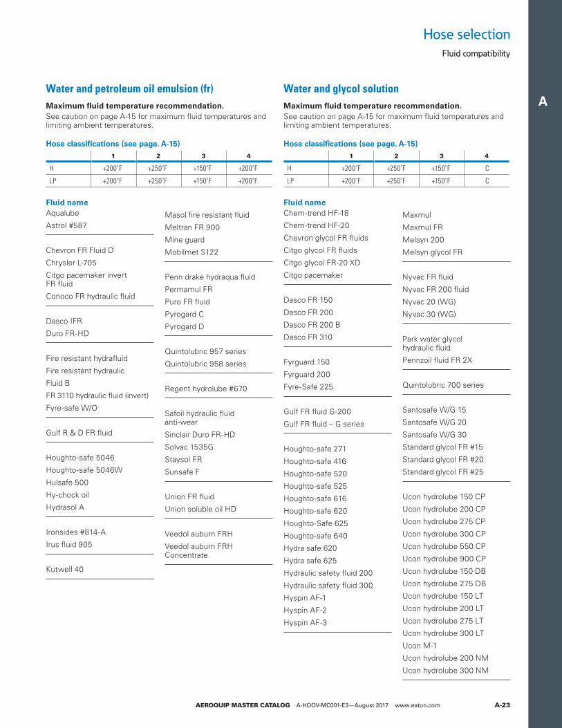
A
AEROQUIP MASTER CATALOG A-HOOV-MC001-E3—August 2017 www.eaton.com A-23
Hose selectionFluid compatibility
Water and petroleum oil emulsion (fr)Maximum fluid temperature recommendation. See caution on page A-15 for maximum fluid temperatures and limiting ambient temperatures.
Water and glycol solutionMaximum fluid temperature recommendation. See caution on page A-15 for maximum fluid temperatures and limiting ambient temperatures.
Hose classifications (see page. A-15)
1 2 3 4
H +200˚F +250˚F +150˚F +200˚F
LP +200˚F +250˚F +150˚F +200˚F
Hose classifications (see page. A-15)
1 2 3 4
H +200˚F +250˚F +150˚F C
LP +200˚F +250˚F +150˚F C
Fluid nameAqualube
Astrol #587
Chevron FR Fluid D
Chrysler L-705
Citgo pacemaker invert FR fluid
Conoco FR hydraulic fluid
Dasco IFR
Duro FR-HD
Fire resistant hydrafluid
Fire resistant hydraulic
Fluid B
FR 3110 hydraulic fluid (invert)
Fyre-safe W/O
Gulf R & D FR fluid
Houghto-safe 5046
Houghto-safe 5046W
Hulsafe 500
Hy-chock oil
Hydrasol A
Ironsides #814-A
Irus fluid 905
Kutwell 40
Masol fire resistant fluid
Meltran FR 900
Mine guard
Mobilmet S122
Penn drake hydraqua fluid
Permamul FR
Puro FR fluid
Pyrogard C
Pyrogard D
Quintolubric 957 series
Quintolubric 958 series
Regent hydrolube #670
Safoil hydraulic fluid anti-wear
Sinclair Duro FR-HD
Solvac 1535G
Staysol FR
Sunsafe F
Union FR fluid
Union soluble oil HD
Veedol auburn FRH
Veedol auburn FRH Concentrate
Fluid nameChem-trend HF-18
Chem-trend HF-20
Chevron glycol FR fluids
Citgo glycol FR fluids
Citgo glycol FR-20 XD
Citgo pacemaker
Dasco FR 150
Dasco FR 200
Dasco FR 200 B
Dasco FR 310
Fyrguard 150
Fyrguard 200
Fyre-Safe 225
Gulf FR fluid G-200
Gulf FR fluid – G series
Houghto-safe 271
Houghto-safe 416
Houghto-safe 520
Houghto-safe 525
Houghto-safe 616
Houghto-safe 620
Houghto-Safe 625
Houghto-safe 640
Hydra safe 620
Hydra safe 625
Hydraulic safety fluid 200
Hydraulic safety fluid 300
Hyspin AF-1
Hyspin AF-2
Hyspin AF-3
Maxmul
Maxmul FR
Melsyn 200
Melsyn glycol FR
Nyvac FR fluid
Nyvac FR 200 fluid
Nyvac 20 (WG)
Nyvac 30 (WG)
Park water glycol hydraulic fluid
Pennzoil fluid FR 2X
Quintolubric 700 series
Santosafe W/G 15
Santosafe W/G 20
Santosafe W/G 30
Standard glycol FR #15
Standard glycol FR #20
Standard glycol FR #25
Ucon hydrolube 150 CP
Ucon hydrolube 200 CP
Ucon hydrolube 275 CP
Ucon hydrolube 300 CP
Ucon hydrolube 550 CP
Ucon hydrolube 900 CP
Ucon hydrolube 150 DB
Ucon hydrolube 275 DB
Ucon hydrolube 150 LT
Ucon hydrolube 200 LT
Ucon hydrolube 275 LT
Ucon hydrolube 300 LT
Ucon M-1
Ucon hydrolube 200 NM
Ucon hydrolube 300 NM
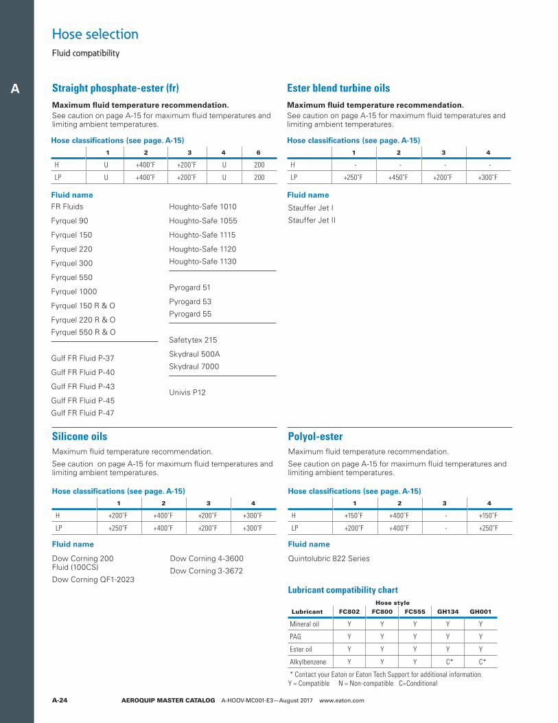
A
AEROQUIP MASTER CATALOG A-HOOV-MC001-E3—August 2017 www.eaton.comA-24
Hose selectionFluid compatibility
Straight phosphate-ester (fr)Maximum fluid temperature recommendation. See caution on page A-15 for maximum fluid temperatures and limiting ambient temperatures.
Lubricant compatibility chartHose style
Lubricant FC802 FC800 FC555 GH134 GH001
Mineral oil Y Y Y Y Y
PAG Y Y Y Y Y
Ester oil Y Y Y Y Y
Alkylbenzene Y Y Y C* C*
* Contact your Eaton or Eaton Tech Support for additional information.
FR Fluids
Fyrquel 90
Fyrquel 150
Fyrquel 220
Fyrquel 300
Fyrquel 550
Fyrquel 1000
Fyrquel 150 R & O
Fyrquel 220 R & O
Fyrquel 550 R & O
Gulf FR Fluid P-37
Gulf FR Fluid P-40
Gulf FR Fluid P-43
Gulf FR Fluid P-45
Gulf FR Fluid P-47
Houghto-Safe 1010
Houghto-Safe 1055
Houghto-Safe 1115
Houghto-Safe 1120
Houghto-Safe 1130
Pyrogard 51
Pyrogard 53
Pyrogard 55
Safetytex 215
Skydraul 500A
Skydraul 7000
Univis P12
Dow Corning 200 Fluid (100CS)
Dow Corning QF1-2023
Dow Corning 4-3600
Dow Corning 3-3672
Fluid name
Fluid name Fluid name
Fluid name
Polyol-esterMaximum fluid temperature recommendation.
See caution on page A-15 for maximum fluid temperatures and limiting ambient temperatures.
Quintolubric 822 Series
Hose classifications (see page. A-15)
1 2 3 4
H +150˚F +400˚F - +150˚F
LP +200˚F +400˚F - +250˚F
Hose classifications (see page. A-15)
1 2 3 4
H - - - -
LP +250˚F +450˚F +200˚F +300˚F
Hose classifications (see page. A-15)
1 2 3 4 6
H U +400˚F +200˚F U 200
LP U +400˚F +200˚F U 200
Hose classifications (see page. A-15)
1 2 3 4
H +200˚F +400˚F +200˚F +300˚F
LP +250˚F +400˚F +200˚F +300˚F
Stauffer Jet I
Stauffer Jet II
Silicone oilsMaximum fluid temperature recommendation.
See caution on page A-15 for maximum fluid temperatures and limiting ambient temperatures.
Ester blend turbine oilsMaximum fluid temperature recommendation. See caution on page A-15 for maximum fluid temperatures and limiting ambient temperatures.
Y = Compatible N = Non-compatible C=Conditional
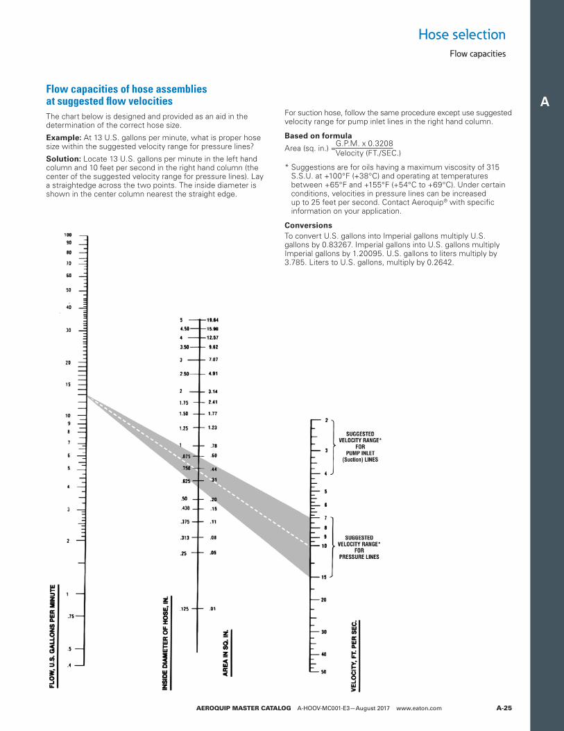
A
AEROQUIP MASTER CATALOG A-HOOV-MC001-E3—August 2017 www.eaton.com A-25
Flow capacities
Hose selection
Flow capacities of hose assemblies at suggested flow velocitiesThe chart below is designed and provided as an aid in the determination of the correct hose size.
Example: At 13 U.S. gallons per minute, what is proper hose size within the suggested velocity range for pressure lines?
Solution: Locate 13 U.S. gallons per minute in the left hand column and 10 feet per second in the right hand column (the center of the suggested velocity range for pressure lines). Lay a straightedge across the two points. The inside diameter is shown in the center column nearest the straight edge.
For suction hose, follow the same procedure except use suggested velocity range for pump inlet lines in the right hand column.
Based on formula
Area (sq. in.) =
* Suggestions are for oils having a maximum viscosity of 315 S.S.U. at +100°F (+38°C) and operating at temperatures between +65°F and +155°F (+54°C to +69°C). Under certain conditions, velocities in pressure lines can be increased up to 25 feet per second. Contact Aeroquip® with specific information on your application.
ConversionsTo convert U.S. gallons into Imperial gallons multiply U.S. gallons by 0.83267. Imperial gallons into U.S. gallons multiply Imperial gallons by 1.20095. U.S. gallons to liters multiply by 3.785. Liters to U.S. gallons, multiply by 0.2642.
G.P.M. x 0.3208Velocity (FT./SEC.)
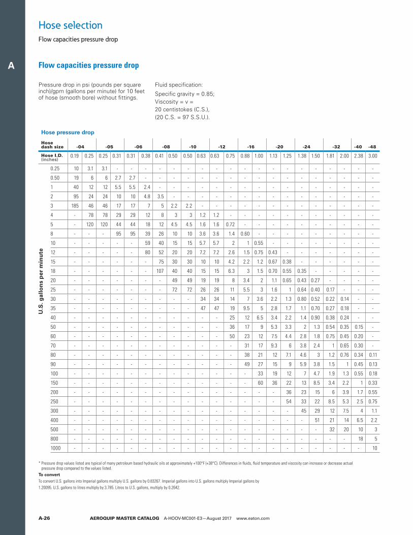
A
AEROQUIP MASTER CATALOG A-HOOV-MC001-E3—August 2017 www.eaton.comA-26
Hose selectionFlow capacities pressure drop
Flow capacities pressure drop
Pressure drop in psi (pounds per square inch)/gpm (gallons per minute) for 10 feet of hose (smooth bore) without fittings.
Fluid specification:
Specific gravity = 0.85;Viscosity = v =20 centistokes (C.S.),(20 C.S. = 97 S.S.U.).
Hose pressure drop
Hose dash size -04 -05 -06 -08 -10 -12 -16 -20 -24 -32 -40 -48
Hose I.D. (inches)
0.19 0.25 0.25 0.31 0.31 0.38 0.41 0.50 0.50 0.63 0.63 0.75 0.88 1.00 1.13 1.25 1.38 1.50 1.81 2.00 2.38 3.00
0.25 10 3.1 3.1 - - - - - - - - - - - - - - - - - - -
0.50 19 6 6 2.7 2.7 - - - - - - - - - - - - - - - - -
1 40 12 12 5.5 5.5 2.4 - - - - - - - - - - - - - - - -
2 95 24 24 10 10 4.8 3.5 - - - - - - - - - - - - - - -
3 185 46 46 17 17 7 5 2.2 2.2 - - - - - - - - - - - - -
4 - 78 78 29 29 12 8 3 3 1.2 1.2 - - - - - - - - - - -
5 - 120 120 44 44 18 12 4.5 4.5 1.6 1.6 0.72 - - - - - - - - - -
8 - - - 95 95 39 26 10 10 3.6 3.6 1.4 0.60 - - - - - - - - -
10 - - - - - 59 40 15 15 5.7 5.7 2 1 0.55 - - - - - - - -
12 - - - - - 80 52 20 20 7.2 7.2 2.6 1.5 0.75 0.43 - - - - - - -
15 - - - - - - 75 30 30 10 10 4.2 2.2 1.2 0.67 0.38 - - - - - -
18 - - - - - - 107 40 40 15 15 6.3 3 1.5 0.70 0.55 0.35 - - - - -
20 - - - - - - - 49 49 19 19 8 3.4 2 1.1 0.65 0.43 0.27 - - - -
25 - - - - - - - 72 72 26 26 11 5.5 3 1.6 1 0.64 0.40 0.17 - - -
30 - - - - - - - - - 34 34 14 7 3.6 2.2 1.3 0.80 0.52 0.22 0.14 - -
35 - - - - - - - - - 47 47 19 9.5 5 2.8 1.7 1.1 0.70 0.27 0.18 - -
40 - - - - - - - - - - - 25 12 6.5 3.4 2.2 1.4 0.90 0.38 0.24 - -
50 - - - - - - - - - - - 36 17 9 5.3 3.3 2 1.3 0.54 0.35 0.15 -
60 - - - - - - - - - - - 50 23 12 7.5 4.4 2.8 1.8 0.75 0.45 0.20 -
70 - - - - - - - - - - - - 31 17 9.3 6 3.8 2.4 1 0.65 0.30 -
80 - - - - - - - - - - - - 38 21 12 7.1 4.6 3 1.2 0.76 0.34 0.11
90 - - - - - - - - - - - - 49 27 15 9 5.9 3.8 1.5 1 0.45 0.13
100 - - - - - - - - - - - - - 33 19 12 7 4.7 1.9 1.3 0.55 0.18
150 - - - - - - - - - - - - - 60 36 22 13 8.5 3.4 2.2 1 0.33
200 - - - - - - - - - - - - - - - 36 23 15 6 3.9 1.7 0.55
250 - - - - - - - - - - - - - - - 54 33 22 8.5 5.3 2.5 0.75
300 - - - - - - - - - - - - - - - - 45 29 12 7.5 4 1.1
400 - - - - - - - - - - - - - - - - - 51 21 14 6.5 2.2
500 - - - - - - - - - - - - - - - - - - 32 20 10 3
800 - - - - - - - - - - - - - - - - - - - - 18 5
1000 - - - - - - - - - - - - - - - - - - - - - 10
U.S
. gal
lon
s p
er m
inu
te
* Pressure drop values listed are typical of many petroleum based hydraulic oils at approximately +100°F (+38°C). Differences in fluids, fluid temperature and viscosity can increase or decrease actual pressure drop compared to the values listed.
To convertTo convert U.S. gallons into Imperial gallons multiply U.S. gallons by 0.83267. Imperial gallons into U.S. gallons multiply Imperial gallons by1.20095. U.S. gallons to litres multiply by 3.785. Litres to U.S. gallons, multiply by 0.2642.
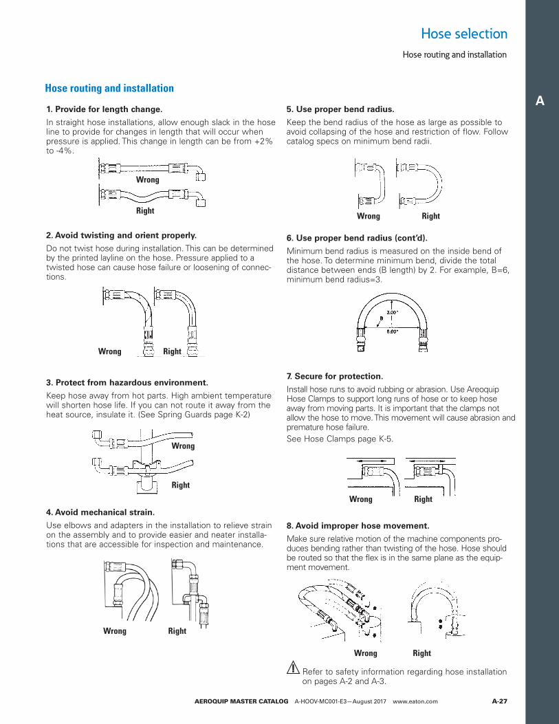
A
AEROQUIP MASTER CATALOG A-HOOV-MC001-E3—August 2017 www.eaton.com A-27
Hose selectionHose routing and installation
Hose routing and installation
1. Provide for length change.
In straight hose installations, allow enough slack in the hose line to provide for changes in length that will occur when pressure is applied. This change in length can be from +2% to -4%.
2. Avoid twisting and orient properly.
Do not twist hose during installation. This can be determined by the printed layline on the hose. Pressure applied to a twisted hose can cause hose failure or loosening of connec-tions.
3. Protect from hazardous environment.
Keep hose away from hot parts. High ambient temperature will shorten hose life. If you can not route it away from the heat source, insulate it. (See Spring Guards page K-2)
4. Avoid mechanical strain.
Use elbows and adapters in the installation to relieve strain on the assembly and to provide easier and neater installa-tions that are accessible for inspection and maintenance.
5. Use proper bend radius.
Keep the bend radius of the hose as large as possible to avoid collapsing of the hose and restriction of flow. Follow catalog specs on minimum bend radii.
6. Use proper bend radius (cont’d).
Minimum bend radius is measured on the inside bend of the hose. To determine minimum bend, divide the total distance between ends (B length) by 2. For example, B=6, minimum bend radius=3.
7. Secure for protection.
Install hose runs to avoid rubbing or abrasion. Use Areoquip Hose Clamps to support long runs of hose or to keep hose away from moving parts. It is important that the clamps not allow the hose to move. This movement will cause abrasion and premature hose failure.See Hose Clamps page K-5.
8. Avoid improper hose movement.
Make sure relative motion of the machine components pro-duces bending rather than twisting of the hose. Hose should be routed so that the flex is in the same plane as the equip-ment movement.
Refer to safety information regarding hose installation on pages A-2 and A-3.
Wrong Right
Wrong Right
Wrong Right
Wrong
Right
Wrong Right
Wrong Right
Wrong
Right
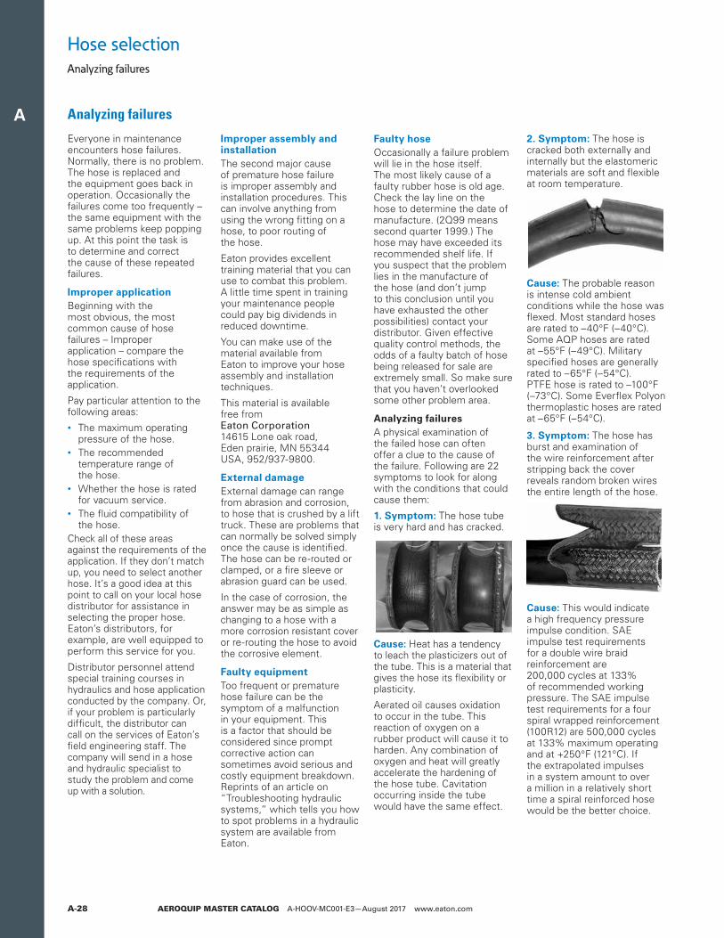
A
AEROQUIP MASTER CATALOG A-HOOV-MC001-E3—August 2017 www.eaton.comA-28
Hose selectionAnalyzing failures
Analyzing failures
Everyone in maintenance encounters hose failures. Normally, there is no problem. The hose is replaced and the equipment goes back in operation. Occasionally the failures come too frequently – the same equipment with the same problems keep popping up. At this point the task is to determine and correct the cause of these repeated failures.
Improper applicationBeginning with the most obvious, the most common cause of hose failures – Improper application – compare the hose specifications with the requirements of the application.
Pay particular attention to the following areas:• The maximum operating
pressure of the hose.• The recommended
temperature range of the hose.
• Whether the hose is rated for vacuum service.
• The fluid compatibility of the hose.
Check all of these areas against the requirements of the application. If they don’t match up, you need to select another hose. It’s a good idea at this point to call on your local hose distributor for assistance in selecting the proper hose. Eaton’s distributors, for example, are well equipped to perform this service for you.
Distributor personnel attend special training courses in hydraulics and hose application conducted by the company. Or, if your problem is particularly difficult, the distributor can call on the services of Eaton’s field engineering staff. The company will send in a hose and hydraulic specialist to study the problem and come up with a solution.
Improper assembly and installationThe second major cause of premature hose failure is improper assembly and installation procedures. This can involve anything from using the wrong fitting on a hose, to poor routing of the hose.
Eaton provides excellent training material that you can use to combat this problem. A little time spent in training your maintenance people could pay big dividends in reduced downtime.
You can make use of the material available from Eaton to improve your hose assembly and installation techniques.
This material is available free from Eaton Corporation 14615 Lone oak road, Eden prairie, MN 55344 USA, 952/937-9800.
External damageExternal damage can range from abrasion and corrosion, to hose that is crushed by a lift truck. These are problems that can normally be solved simply once the cause is identified. The hose can be re-routed or clamped, or a fire sleeve or abrasion guard can be used.
In the case of corrosion, the answer may be as simple as changing to a hose with a more corrosion resistant cover or re-routing the hose to avoid the corrosive element.
Faulty equipmentToo frequent or premature hose failure can be the symptom of a malfunction in your equipment. This is a factor that should be considered since prompt corrective action can sometimes avoid serious and costly equipment breakdown. Reprints of an article on “Troubleshooting hydraulic systems,” which tells you how to spot problems in a hydraulic system are available from Eaton.
Faulty hoseOccasionally a failure problem will lie in the hose itself. The most likely cause of a faulty rubber hose is old age. Check the lay line on the hose to determine the date of manufacture. (2Q99 means second quarter 1999.) The hose may have exceeded its recommended shelf life. If you suspect that the problem lies in the manufacture of the hose (and don’t jump to this conclusion until you have exhausted the other possibilities) contact your distributor. Given effective quality control methods, the odds of a faulty batch of hose being released for sale are extremely small. So make sure that you haven’t overlooked some other problem area.
Analyzing failuresA physical examination of the failed hose can often offer a clue to the cause of the failure. Following are 22 symptoms to look for along with the conditions that could cause them:
1. Symptom: The hose tube is very hard and has cracked.
Cause: Heat has a tendency to leach the plasticizers out of the tube. This is a material that gives the hose its flexibility or plasticity.
Aerated oil causes oxidation to occur in the tube. This reaction of oxygen on a rubber product will cause it to harden. Any combination of oxygen and heat will greatly accelerate the hardening of the hose tube. Cavitation occurring inside the tube would have the same effect.
2. Symptom: The hose is cracked both externally and internally but the elastomeric materials are soft and flexible at room temperature.
Cause: The probable reason is intense cold ambient conditions while the hose was flexed. Most standard hoses are rated to –40°F (–40°C). Some AQP hoses are rated at –55°F (–49°C). Military specified hoses are generally rated to –65°F (–54°C). PTFE hose is rated to –100°F (–73°C). Some Everflex Polyon thermoplastic hoses are rated at –65°F (–54°C).
3. Symptom: The hose has burst and examination of the wire reinforcement after stripping back the cover reveals random broken wires the entire length of the hose.
Cause: This would indicatea high frequency pressure impulse condition. SAE impulse test requirements for a double wire braid reinforcement are 200,000 cycles at 133% of recommended working pressure. The SAE impulse test requirements for a four spiral wrapped reinforcement (100R12) are 500,000 cycles at 133% maximum operating and at +250°F (121°C). If the extrapolated impulses in a system amount to over a million in a relatively short time a spiral reinforced hose would be the better choice.
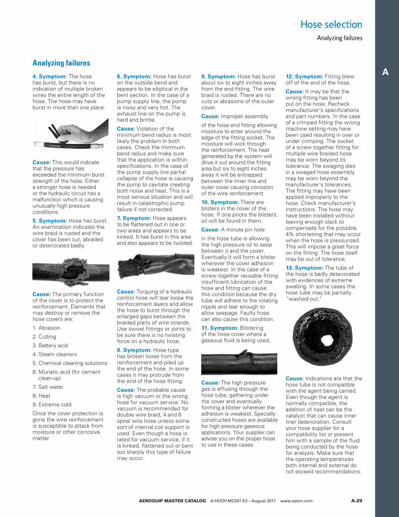
A
AEROQUIP MASTER CATALOG A-HOOV-MC001-E3—August 2017 www.eaton.com A-29
Analyzing failures
Analyzing failures
4. Symptom: The hose has burst, but there is no indication of multiple broken wires the entire length of the hose. The hose may have burst in more than one place.
Cause: This would indicate that the pressure has exceeded the minimum burst strength of the hose. Either a stronger hose is needed or the hydraulic circuit has a malfunction which is causing unusually high pressure conditions.
5. Symptom: Hose has burst. An examination indicates the wire braid is rusted and the cover has been cut, abraded or deteriorated badly.
Cause: The primary function of the cover is to protect the reinforcement. Elements that may destroy or remove the hose covers are:
1. Abrasion
2. Cutting
3. Battery acid
4. Steam cleaners
5. Chemical cleaning solutions
6. Muriatic acid (for cement clean-up)
7. Salt water
8. Heat
9. Extreme cold
Once the cover protection is gone the wire reinforcement is susceptible to attack from moisture or other corrosive matter.
6. Symptom: Hose has burst on the outside bend and appears to be elliptical in the bent section. In the case of a pump supply line, the pump is noisy and very hot. The exhaust line on the pump is hard and brittle.
Cause: Violation of the minimum bend radius is most likely the problem in both cases. Check the minimum bend radius and make sure that the application is within specifications. In the case of the pump supply line partial collapse of the hose is causing the pump to cavitate creating both noise and heat. This is a most serious situation and will result in catastrophic pump failure if not corrected.
7. Symptom: Hose appears to be flattened out in one or two areas and appears to be kinked. It has burst in this area and also appears to be twisted.
Cause: Torquing of a hydraulic control hose will tear loose the reinforcement layers and allow the hose to burst through the enlarged gaps between the braided plaits of wire strands. Use swivel fittings or joints to be sure there is no twisting force on a hydraulic hose.
8. Symptom: Hose type has broken loose from the reinforcement and piled up the end of the hose. In some cases it may protrude from the end of the hose fitting.
Cause: The probable cause is high vacuum or the wrong hose for vacuum service. No vacuum is recommended for double wire braid, 4 and 6 spiral wire hose unless some sort of internal coil support is used. Even though a hose is rated for vacuum service, if it is kinked, flattened out or bent too sharply this type of failure may occur.
9. Symptom: Hose has burst about six to eight inches away from the end fitting. The wire braid is rusted. There are no cuts or abrasions of the outer cover.
Cause: Improper assembly
of the hose end fitting allowing moisture to enter around the edge of the fitting socket. The moisture will wick through the reinforcement. The heat generated by the system will drive it out around the fitting area but six to eight inches away it will be entrapped between the inner line and outer cover causing corrosion of the wire reinforcement.
10. Symptom: There are blisters in the cover of the hose. If one pricks the blisters, oil will be found in them.
Cause: A minute pin hole
in the hose tube is allowing the high pressure oil to seep between it and the cover. Eventually it will form a blister wherever the cover adhesion is weakest. In the case of a screw together reusable fitting insufficient lubrication of the hose and fitting can cause this condition because the dry tube will adhere to the rotating nipple and tear enough to allow seepage. Faulty hose can also cause this condition.
11. Symptom: Blistering of the hose cover where a gaseous fluid is being used.
Cause: The high pressure gas is effusing through the hose tube, gathering under the cover and eventually forming a blister wherever the adhesion is weakest. Specially constructed hoses are available for high pressure gaseous applications. Your supplier can advise you on the proper hose to use in these cases.
12. Symptom: Fitting blew off of the end of the hose.
Cause: It may be that the wrong fitting has been put on the hose. Recheck manufacturer’s specifications and part numbers. In the case of a crimped fitting the wrong machine setting may have been used resulting in over or under crimping. The socket of a screw together fitting for multiple wire braided hose may be worn beyond its tolerance. The swaging dies in a swaged hose assembly may be worn beyond the manufacturer’s tolerances. The fitting may have been applied improperly to the hose. Check manufacturer’s instructions. The hose may have been installed without leaving enough slack to compensate for the possible 4% shortening that may occur when the hose is pressurized. This will impose a great force on the fitting. The hose itself may be out of tolerance.
13. Symptom: The tube of the hose is badly deteriorated with evidences of extreme swelling. In some cases the hose tube may be partially “washed out.”
Cause: Indications are that the hose tube is not compatible with the agent being carried. Even though the agent is normally compatible, the addition of heat can be the catalyst that can cause inner liner deterioration. Consult your hose supplier for a compatibility list or present him with a sample of the fluid being conducted by the hose for analysis. Make sure that the operating temperatures both internal and external do not exceed recommendations.
Hose selection
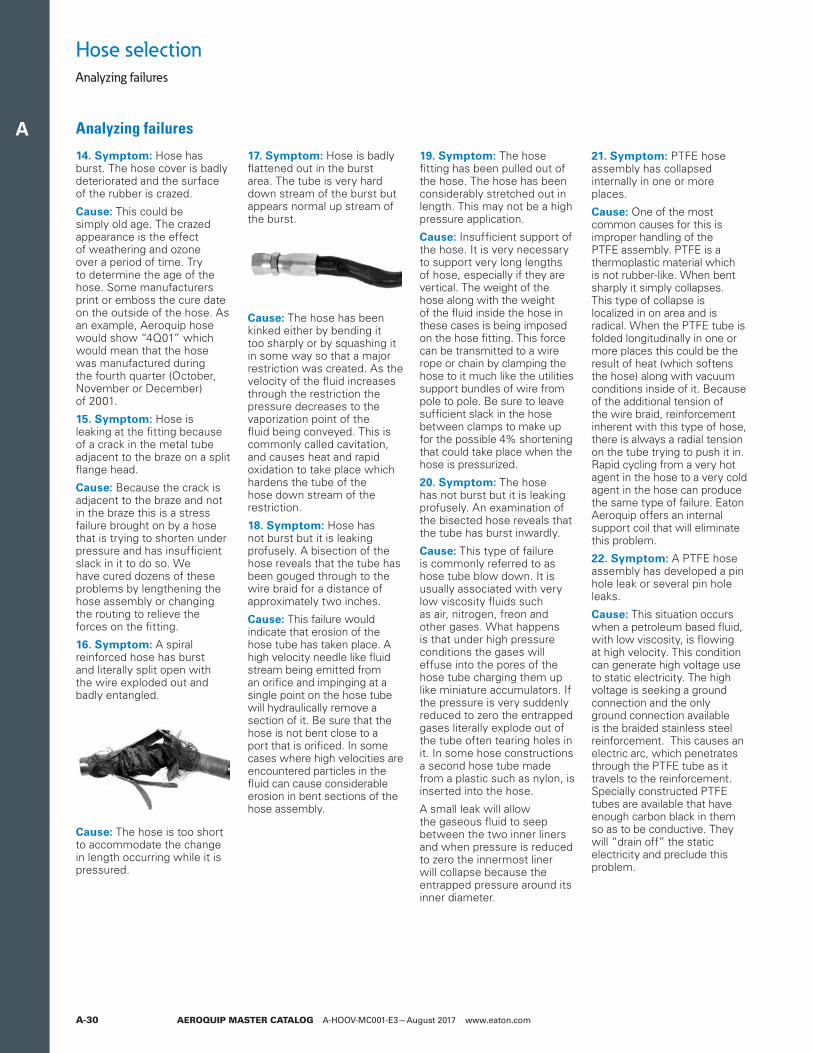
A
AEROQUIP MASTER CATALOG A-HOOV-MC001-E3—August 2017 www.eaton.comA-30
14. Symptom: Hose has burst. The hose cover is badly deteriorated and the surface of the rubber is crazed.
Cause: This could be simply old age. The crazed appearance is the effect of weathering and ozone over a period of time. Try to determine the age of the hose. Some manufacturers print or emboss the cure date on the outside of the hose. As an example, Aeroquip hose would show “4Q01” which would mean that the hose was manufactured during the fourth quarter (October, November or December) of 2001.
15. Symptom: Hose is leaking at the fitting because of a crack in the metal tube adjacent to the braze on a split flange head.
Cause: Because the crack is adjacent to the braze and not in the braze this is a stress failure brought on by a hose that is trying to shorten under pressure and has insufficient slack in it to do so. We have cured dozens of these problems by lengthening the hose assembly or changing the routing to relieve the forces on the fitting.
16. Symptom: A spiral reinforced hose has burst and literally split open with the wire exploded out and badly entangled.
Cause: The hose is too short to accommodate the change in length occurring while it is pressured.
17. Symptom: Hose is badly flattened out in the burst area. The tube is very hard down stream of the burst but appears normal up stream of the burst.
Cause: The hose has been kinked either by bending it too sharply or by squashing it in some way so that a major restriction was created. As the velocity of the fluid increases through the restriction the pressure decreases to the vaporization point of the fluid being conveyed. This is commonly called cavitation, and causes heat and rapid oxidation to take place which hardens the tube of the hose down stream of the restriction.
18. Symptom: Hose has not burst but it is leaking profusely. A bisection of the hose reveals that the tube has been gouged through to the wire braid for a distance of approximately two inches.
Cause: This failure would indicate that erosion of the hose tube has taken place. A high velocity needle like fluid stream being emitted from an orifice and impinging at a single point on the hose tube will hydraulically remove a section of it. Be sure that the hose is not bent close to a port that is orificed. In some cases where high velocities are encountered particles in the fluid can cause considerable erosion in bent sections of the hose assembly.
19. Symptom: The hose fitting has been pulled out of the hose. The hose has been considerably stretched out in length. This may not be a high pressure application.
Cause: Insufficient support of the hose. It is very necessary to support very long lengths of hose, especially if they are vertical. The weight of the hose along with the weight of the fluid inside the hose in these cases is being imposed on the hose fitting. This force can be transmitted to a wire rope or chain by clamping the hose to it much like the utilities support bundles of wire from pole to pole. Be sure to leave sufficient slack in the hose between clamps to make up for the possible 4% shortening that could take place when the hose is pressurized.
20. Symptom: The hose has not burst but it is leaking profusely. An examination of the bisected hose reveals that the tube has burst inwardly.
Cause: This type of failure is commonly referred to as hose tube blow down. It is usually associated with very low viscosity fluids such as air, nitrogen, freon and other gases. What happens is that under high pressure conditions the gases will effuse into the pores of the hose tube charging them up like miniature accumulators. If the pressure is very suddenly reduced to zero the entrapped gases literally explode out of the tube often tearing holes in it. In some hose constructions a second hose tube made from a plastic such as nylon, is inserted into the hose.
A small leak will allow the gaseous fluid to seep between the two inner liners and when pressure is reduced to zero the innermost liner will collapse because the entrapped pressure around its inner diameter.
21. Symptom: PTFE hose assembly has collapsed internally in one or more places.
Cause: One of the most common causes for this is improper handling of the PTFE assembly. PTFE is a thermoplastic material which is not rubber-like. When bent sharply it simply collapses. This type of collapse is localized in on area and is radical. When the PTFE tube is folded longitudinally in one or more places this could be the result of heat (which softens the hose) along with vacuum conditions inside of it. Because of the additional tension of the wire braid, reinforcement inherent with this type of hose, there is always a radial tension on the tube trying to push it in. Rapid cycling from a very hot agent in the hose to a very cold agent in the hose can produce the same type of failure. Eaton Aeroquip offers an internal support coil that will eliminate this problem.
22. Symptom: A PTFE hose assembly has developed a pin hole leak or several pin hole leaks.
Cause: This situation occurs when a petroleum based fluid, with low viscosity, is flowing at high velocity. This condition can generate high voltage use to static electricity. The high voltage is seeking a ground connection and the only ground connection available is the braided stainless steel reinforcement. This causes an electric arc, which penetrates through the PTFE tube as it travels to the reinforcement. Specially constructed PTFE tubes are available that have enough carbon black in them so as to be conductive. They will “drain off” the static electricity and preclude this problem.
Hose selectionAnalyzing failures
Analyzing failures
A
AEROQUIP MASTER CATALOG A-HOOV-MC001-E3—August 2017 www.eaton.com A-31
Fluid connectorsFluid connectors identification
Measuring Tools: A seat angle gauge, thread pitch gauge and an I.D./O.D. caliper are necessary to make accurate measurements of commonly used connectors. Eaton offers a unique new caliper than offers the capabilities of both a caliper and a seat angle gauge in one unit.
Female connections are usually measured by inserting the gauge into the connection and placing it on the sealing surface. If the centerlines of the connection and gauge are parallel, the correct angle has been determined.
Male flare type connectors are usually measured by placing the gauge on the sealing surface. If the centerlines of the connection and gauge are parallel, the correct angle has been determined.
Use a thread pitch gauge to determine the number of threads per inch or the distance between threads in metric connections. Place the gauge on the threads until the fit is snug. Match the measurement to the charts.
How to measure threads
I.D./O.D. Angle gauge caliper Thread pitch gauge
Fluid connectors identification
How to measure sealing surface angles
Measure the thread diameter with an I.D./O.D. caliper as shown. Match the measurements to the charts.
FT1341
Identification Tool Kit
A
AEROQUIP MASTER CATALOG A-HOOV-MC001-E3—August 2017 www.eaton.comA-32
Fluid connectorsThread size chart
Thread size chart
The following chart is intended as a quick reference guide for thread size by dash size.
Dashsize N.P.T.F.
N.P.S.M.approx. dia.
SAE 45°auto. refrig.
SAE 37° (J.I.C.)hydraulic
SAE O-Ringboss
P.T.T. 30°automotive
SAE invert.flare ORS
–02 1/8–27 1/8–27 5/16–24 5/16–24 5/16–24 - 5/16–24 -
–03 - - 3/8–24 3/8–24 3/8–24 - 3/8–24 -
–04 1/4–18 1/4–18 7/16–20 7/16–20 7/16–20 - 7/16–24 9/16–18
–05 - - 1/2–20 1/2–20 1/2–20 - 1/2–20 -
–06 3/8–18 3/8–18 5/8–18 9/16–18 9/16–18 - 5/8–18 11/16–16
–07 - - 11/16–24 - - - 11/16–18 -
–08 1/2–14 1/2–14 3/4–16 3/4–16 3/4–16 - 3/4–18 1 3/16–16
–10 - - 7/8–14 7/8–14 7/8–14 - 7/8–18 1–14
–12 3/4–14 3/4–14 1 1/16–14 1 1/16–12 1 1/16–12 - 1 1/16–16 13/16–12
–14 - - - 1 3/16–12 1 3/16–12 - - -
–16 1–11 1/2 1–11 1/2 - 1 5/16–12 1 5/16–12 1 5/16–14 - 1 7/16–12
–20 1 1/4–11 1/2 1 1/4–11 1/2 - 1 5/8–12 1 5/8–12 1 5/8–14 - 1 11/16–12
–24 1 1/2–11 1/2 1 1/2–11 1/2 - 1 7/8–12 1 7/8–12 1 7/8–14 - 2–12
–32 2–11 1/2 2–11 1/2 - 2 1/2–12 2 1/2–12 2 1/2–12 - -
–40 2 1/2–8 2 1/2–8 - 3–12 3–12 - - -
–48 3–8 3–8 - 3 1/2–12 3 1/2–12 - - -
EThrough
Hole
EThrough
Hole
SAE 37°
ORS
Through hole dimensionsAll dimensions are nominal. In jump size bodies, the minimum through hole dimensions will correspond to the smallest dash size.
Dash size E through hole
SAE 37° ORS
mm in mm in
–03 3,0 0.12 - -
–04 4,3 0.17 4,3 0.17
–05 5,8 0.23 - -
–06 7,6 0.30 6,6 0.26
–08 9,9 0.39 9,7 0.38
–10 12,2 0.48 12,2 0.48
–12 15,5 0.61 15,5 0.61
–16 21,3 0.84 20,6 0.81
–20 25,8 1.08 26,7 1.05
–24 33,3 1.31 33,3 1.31
–32 45,2 1.78 - -
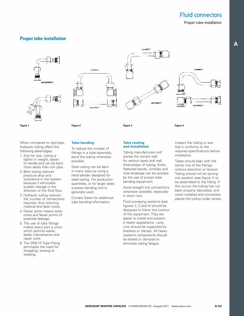
A
AEROQUIP MASTER CATALOG A-HOOV-MC001-E3—August 2017 www.eaton.com A-33
Proper tube installation
Tube bending
To reduce the number of fittings in a tube assembly, bend the tubing whenever possible.
Steel tubing can be bent in many sizes by using a hand bender designed for steel tubing. For production quantities, or for larger sizes, a power bending tool is generally used.
Contact Eaton for additional tube bending information.
Tube routing and installation
Tubing manufacturers will advise the correct radii for various types and wall thicknesses of tubing. Kinks, flattened bends, wrinkles and tube breakage can be avoided by the use of proper tube bending equipment.
Avoid straight line connections whenever possible, especially in short runs.
Fluid conveying systems (see figures 2, 3 and 4) should be designed to follow the contour of the equipment. They are easier to install and present a neater appearance. Long runs should be supported by brackets or clamps. All heavy systems components should be bolted or clamped to eliminate tubing fatigue.
Inspect the tubing to see that it conforms to the required specifications before installation.
Tubes should align with the center line of the fittings, without distortion or tension. Tubing should not be sprung into position (see figure 1) to be assembled to the fitting. If this occurs the tubing has not been properly fabricated, and when installed and connected, places the tubing under stress.
When compared to rigid pipe, hydraulic tubing offers the following advantages:1. Size for size, tubing is
lighter in weight, easier to handle and can be bent more easily than iron pipe.
2. Bent tubing reduces pressure drop and turbulence in the system because it eliminates sudden change in the direction of the fluid flow.
3. Hydraulic tubing reduces the number of connections required, thus reducing material and labor costs.
4. Fewer joints means lower costs and fewer points of potential leakage.
5. The use of tube fittings makes every joint a union which permits easier, faster maintenance and repair work.
6. The ORS-TF Tube Fitting eliminates the need for threading, brazing or welding.
Figure 1 Figure 2 Figure 3 Figure 4
Fluid connectorsProper tube installation
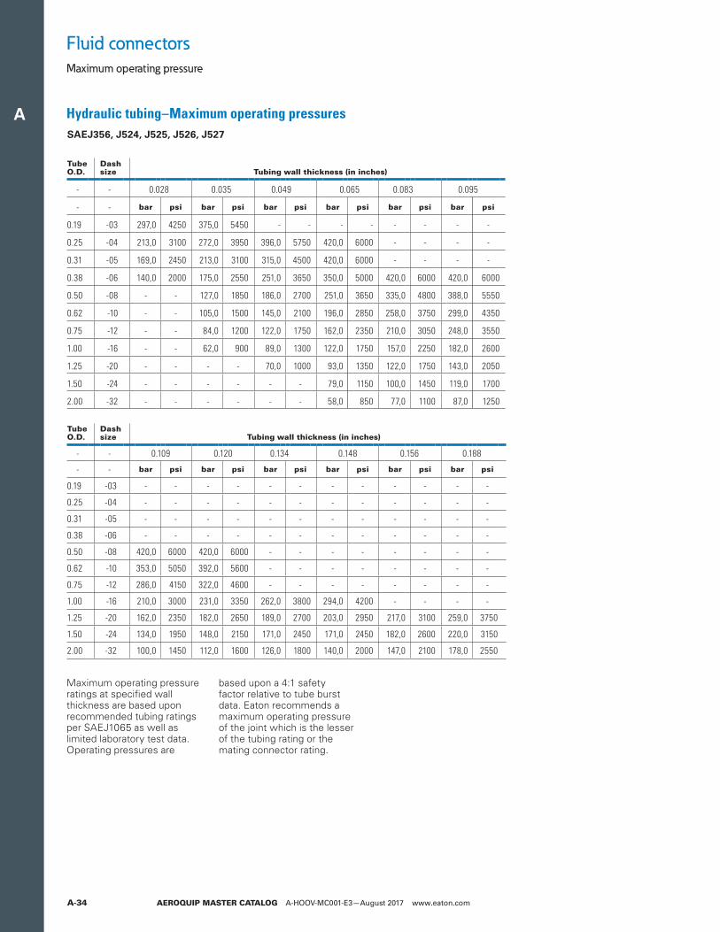
A
AEROQUIP MASTER CATALOG A-HOOV-MC001-E3—August 2017 www.eaton.comA-34
Fluid connectorsMaximum operating pressure
Hydraulic tubing–Maximum operating pressures SAEJ356, J524, J525, J526, J527
Maximum operating pressure ratings at specified wall thickness are based upon recommended tubing ratings per SAEJ1065 as well as limited laboratory test data. Operating pressures are
based upon a 4:1 safety factor relative to tube burst data. Eaton recommends a maximum operating pressure of the joint which is the lesser of the tubing rating or the mating connector rating.
TubeO.D.
Dashsize Tubing wall thickness (in inches)
- - 0.028 0.035 0.049 0.065 0.083 0.095
- - bar psi bar psi bar psi bar psi bar psi bar psi
0.19 -03 297,0 4250 375,0 5450 - - - - - - - -
0.25 -04 213,0 3100 272,0 3950 396,0 5750 420,0 6000 - - - -
0.31 -05 169,0 2450 213,0 3100 315,0 4500 420,0 6000 - - - -
0.38 -06 140,0 2000 175,0 2550 251,0 3650 350,0 5000 420,0 6000 420,0 6000
0.50 -08 - - 127,0 1850 186,0 2700 251,0 3650 335,0 4800 388,0 5550
0.62 -10 - - 105,0 1500 145,0 2100 196,0 2850 258,0 3750 299,0 4350
0.75 -12 - - 84,0 1200 122,0 1750 162,0 2350 210,0 3050 248,0 3550
1.00 -16 - - 62,0 900 89,0 1300 122,0 1750 157,0 2250 182,0 2600
1.25 -20 - - - - 70,0 1000 93,0 1350 122,0 1750 143,0 2050
1.50 -24 - - - - - - 79,0 1150 100,0 1450 119,0 1700
2.00 -32 - - - - - - 58,0 850 77,0 1100 87,0 1250
TubeO.D.
Dashsize Tubing wall thickness (in inches)
- - 0.109 0.120 0.134 0.148 0.156 0.188
- - bar psi bar psi bar psi bar psi bar psi bar psi
0.19 -03 - - - - - - - - - - - -
0.25 -04 - - - - - - - - - - - -
0.31 -05 - - - - - - - - - - - -
0.38 -06 - - - - - - - - - - - -
0.50 -08 420,0 6000 420,0 6000 - - - - - - - -
0.62 -10 353,0 5050 392,0 5600 - - - - - - - -
0.75 -12 286,0 4150 322,0 4600 - - - - - - - -
1.00 -16 210,0 3000 231,0 3350 262,0 3800 294,0 4200 - - - -
1.25 -20 162,0 2350 182,0 2650 189,0 2700 203,0 2950 217,0 3100 259,0 3750
1.50 -24 134,0 1950 148,0 2150 171,0 2450 171,0 2450 182,0 2600 220,0 3150
2.00 -32 100,0 1450 112,0 1600 126,0 1800 140,0 2000 147,0 2100 178,0 2550
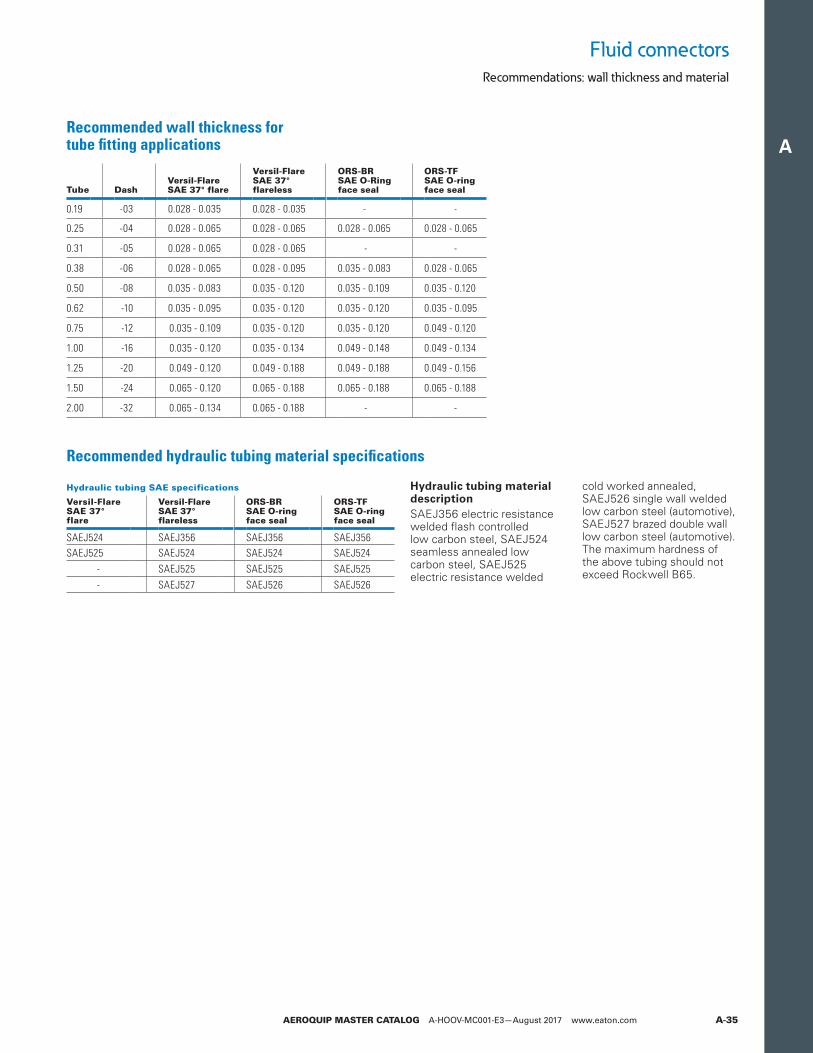
A
AEROQUIP MASTER CATALOG A-HOOV-MC001-E3—August 2017 www.eaton.com A-35
Fluid connectorsRecommendations: wall thickness and material
Recommended wall thickness for tube fitting applications
Recommended hydraulic tubing material specifications
Tube DashVersil-FlareSAE 37° flare
Versil-FlareSAE 37°flareless
ORS-BRSAE O-Ringface seal
ORS-TFSAE O-ringface seal
0.19 -03 0.028 - 0.035 0.028 - 0.035 - -
0.25 -04 0.028 - 0.065 0.028 - 0.065 0.028 - 0.065 0.028 - 0.065
0.31 -05 0.028 - 0.065 0.028 - 0.065 - -
0.38 -06 0.028 - 0.065 0.028 - 0.095 0.035 - 0.083 0.028 - 0.065
0.50 -08 0.035 - 0.083 0.035 - 0.120 0.035 - 0.109 0.035 - 0.120
0.62 -10 0.035 - 0.095 0.035 - 0.120 0.035 - 0.120 0.035 - 0.095
0.75 -12 0.035 - 0.109 0.035 - 0.120 0.035 - 0.120 0.049 - 0.120
1.00 -16 0.035 - 0.120 0.035 - 0.134 0.049 - 0.148 0.049 - 0.134
1.25 -20 0.049 - 0.120 0.049 - 0.188 0.049 - 0.188 0.049 - 0.156
1.50 -24 0.065 - 0.120 0.065 - 0.188 0.065 - 0.188 0.065 - 0.188
2.00 -32 0.065 - 0.134 0.065 - 0.188 - -
Hydraulic tubing SAE specifications
Versil-Flare SAE 37°flare
Versil-FlareSAE 37°flareless
ORS-BRSAE O-ringface seal
ORS-TFSAE O-ringface seal
SAEJ524 SAEJ356 SAEJ356 SAEJ356SAEJ525 SAEJ524 SAEJ524 SAEJ524
- SAEJ525 SAEJ525 SAEJ525- SAEJ527 SAEJ526 SAEJ526
Hydraulic tubing material descriptionSAEJ356 electric resistance welded flash controlled low carbon steel, SAEJ524 seamless annealed low carbon steel, SAEJ525 electric resistance welded
cold worked annealed, SAEJ526 single wall welded low carbon steel (automotive), SAEJ527 brazed double wall low carbon steel (automotive). The maximum hardness of the above tubing should not exceed Rockwell B65.
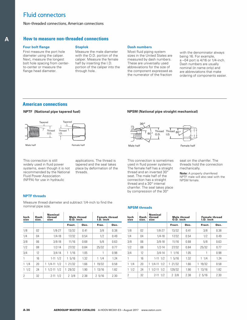
A
AEROQUIP MASTER CATALOG A-HOOV-MC001-E3—August 2017 www.eaton.comA-36
How to measure non-threaded connections
Fluid connectorsNon-threaded connections, American connections
Four bolt flangeFirst measure the port hole diameter using the caliper. Next, measure the longest bolt hole spacing from center- to-center or measure the flange head diameter.
StaplokMeasure the male diameter with the O.D. portion of the caliper. Measure the female half by inserting the I.D. portion of the caliper into the through hole.
Measure thread diameter and subtract 1/4-inch to find the nominal pipe size.
Dash numbersMost fluid piping system sizes in the United States are measured by dash numbers. These are universally used abbreviations for the size of the component expressed as the numerator of the fraction
with the denominator always being 16. For example, a –04 port is 4/16 or 1/4-inch. Dash numbers are usually nominal (in name only) and are abbreviations that make ordering of components easier.
American connections
NPTF threads
NPSM threads
This connection is still widely used in fluid power systems, even though it is not recommended by the National Fluid Power Association (NFPA) for use in hydraulic
applications. The thread is tapered and the seal takes place by deformation of the threads.
NPTF (National pipe tapered fuel)
Tapered
ThreadO.D.
ThreadI.D.
Tapered
Male half Female half
This connection is sometimes used in fluid power systems. The female half has a straight thread and an inverted 30° seat. The male half of the connection has a straight thread and a 30° internal chamfer. The seal takes place by compression of the 30°
seat on the chamfer. The threads hold the connection mechanically.
ote:N A properly chamfered NPTF male will also seal with the NPSM female.
NPSM (National pipe straight mechanical)
ThreadO.D.
ThreadI.D.
Male half Female half
Inch size
Dash size.
Nominalthreadsize
Male thread O.D. inch
Female threadI.D. inch
Fract. Dec. Frac. Dec.
1/8 02 1/8-27 13/32 0.41 3/8 0.38
1/4 04 1/4-18 17/32 0.54 1/2 0.49
3/8 06 3/8-18 11/16 0.68 5/8 0.63
1/2 08 1/2-14 27/32 0.84 25/32 0.77
3/4 12 3/4-14 1 1/16 1.05 1 0.98
1 16 1-11 1/2 1 5/16 1.32 1 1/4 1.24
1 1/4 20 1 1/4-11 1/2 1 21/32 1.66 1 19/32 0.58
1 1/2 24 1 1/2-11 1/2 1 29/32 1.90 1 13/16 1.82
2 32 2-11 1/2 2 3/8 2.38 2 5/16 2.30
Inch size
Dash size.
Nominalthreadsize
Male thread O.D. inch
Female threadI.D. inch
Fract. Dec. Fract. Dec.
1/8 02 1/8-27 13/32 0.41 3/8 0.38
1/4 04 1/4-18 17/32 0.54 1/2 0.49
3/8 06 3/8-18 11/16 0.68 5/8 0.63
1/2 08 1/2-14 27/32 0.84 25/32 0.77
3/4 12 3/4-14 1 1/16 1.05 1 0.98
1 16 1-11 1/2 1 5/16 1.32 1 1/4 1.24
1 1/4 20 1 1/4-11 1/2 1 21/32 1.66 1 19/32 0.58
1 1/2 24 1 1/2-11 1/2 129/32 1.90 1 13/16 1.82
2 32 2-11 1/2 2 3/8 2.38 2 5/16 2.30
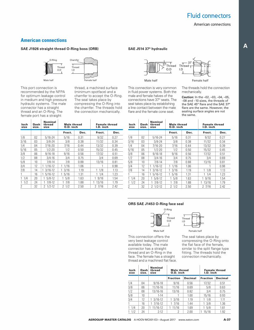
A
AEROQUIP MASTER CATALOG A-HOOV-MC001-E3—August 2017 www.eaton.com A-37
American connections
SAE J1926 straight thread O-Ring boss (ORB)
ORS SAE J1453 O-Ring face seal
Inch size
Dash size.
Nominalthreadsize
Male thread O.D. inch
Female threadI.D. inch
Fract. Dec. Fract. Dec.
1/8 02 5/16-24 5/16 0.31 9/32 0.273/16 03 3/8-24 3/8 0.38 11/32 0.341/4 04 7/16-20 7/16 0.44 13/32 0.395/16 05 1/2-20 1/2 0.50 15/32 0.453/8 06 9/16-18 9/16 0.56 17/32 0.511/2 08 3/4-16 3/4 0.75 3/4 0.695/8 10 7/8-14 7/8 0.88 13/16 0.813/4 12 1 1/16-12 1 1/16 1.06 1 0.987/8 14 1 3/16-12 1 3/16 1.19 1 1/8 1.131 16 1 5/16-12 1 5/16 1.31 1 1/4 1.231 1/4 20 1 5/8-12 1 5/8 1.63 1 9/16 1.541 1/2 24 1 7/8-12 1 7/8 1.88 1 13/16 1.792 32 2 1/2-12 2 1/2 2.50 2 7/16 2.42
Inch size
Dash size.
Nominalthreadsize
Male thread O.D. inch
Female threadI.D. inch
Fraction Decimal Fraction Decimal
1/4 04 9/16-18 9/16 0.56 17/32 0.513/8 06 11/16-16 11/16 0.69 5/8 0.631/2 08 13/16-16 13/16 0.82 3/4 0.755/8 10 1-14 1 1.00 15/16 0.933/4 12 1 3/16-12 1 3/16 1.19 1 1/8 1.111 16 1 7/16-12 1 7/16 1.44 1 3/8 1.361 1/4 20 1 11/16-12 1 11/16 1.69 1 5/8 1.611 1/2 24 2-12 2 2.00 1 15/16 1.92
Male half Female half
O-Ring Chamfer
Thread O.D
Thread I.D
Male half Female half
O-Ring
Thread O.D
Thread I.D
This port connection is recommended by the NFPA for optimum leakage control in medium and high pressure hydraulic systems. The male connector has a straight thread and an O-Ring. The female port has a straight
thread, a machined surface (minimum spotface) and a chamfer to accept the O-Ring. The seal takes place by compressing the O-Ring into the chamfer. The threads hold the connection mechanically.
This connection offers the very best leakage control available today. The male connector has a straight thread and an O-Ring in the face. The female has a straight thread and a machined flat face.
The seal takes place by compressing the O-Ring onto the flat face of the female, similar to the split flange type fitting. The threads hold the connection mechanically.
SAE J514 37° hydraulic
Male half
37º 37º
Female half
Thread O.D
Thread I.D
This connection is very common in fluid power systems. Both the male and female halves of the connections have 37° seats. The seal takes place by establishing a line contact between the male flare and the female cone seat.
The threads hold the connection mechanically. Caution: In the –02, –03, –04, –05, –08 and –10 sizes, the threads of the SAE 45° flare and the SAE 37° flare are the same. However, the sealing surface angles are not the same.
Fluid connectorsAmerican connections
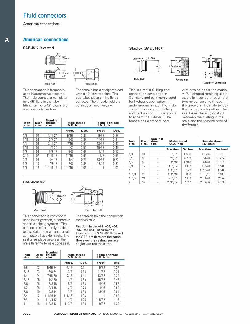
A
AEROQUIP MASTER CATALOG A-HOOV-MC001-E3—August 2017 www.eaton.comA-38
Inch size
Dash size.
Nominalthreadsize
Male thread O.D. inch
Female threadI.D. inch
Fract. Dec. Fract. Dec.
1/8 02 5/16-24 5/16 0.32 9/32 0.283/16 03 3/8-24 3/8 0.38 11/32 0.341/4 04 7/16-24 7/16 0.44 13/32 0.405/16 05 1/2-20 1/2 0.50 15/32 0.453/8 06 5/8-18 5/8 0.63 9/16 0.577/16 07 11/16-18 11/16 0.69 5/8 0.631/2 08 3/4-18 3/4 0.75 23/32 0.705/8 10 7/8-18 7/8 0.88 13/16 0.823/4 12 1 1/16-16 1 1/16 1.06 1 1.00
SAE J512 inverted
Male half
45º
42º
42º
Female half
Thread O.D
Thread O.D
Thread I.D
This connection is frequently used in automotive systems. The male connector can either be a 45° flare in the tube fitting form or a 42° seat in the machined adapter form.
The female has a straight thread with a 42° inverted flare. The seal takes place on the flared surfaces. The threads hold the connection mechanically.
Fluid connectorsAmerican connections
American connections
Staplok (SAE J1467)
This is a radial O-Ring seal connection developed in Germany and commonly used for hydraulic application in underground mines. The male contains an exterior O-Ring and backup ring, plus a groove to accept the “staple”. The female has a smooth bore
with two holes for the stable. A “U” shaped retaining clip or staple is inserted through the two holes, passing through the groove in the male to lock the connection together. The seal takes place by contact between the O-Ring in the male and the smooth bore of the female.
Inch size
Dash size.
Nominalthreadsize
Male thread O.D. inch
Female threadI.D. inch
Fraction Decimal Fraction Decimal
1/4 04 - 9/32 0.586 1 9/32 0.5973/8 06 - 25/32 0.783 51/64 0.7941/2 08 - 15/16 0.940 61/64 0.9513/4 12 - 1 9/64 1.137 1 9/64 1.1481 16 - 1 17/32 1.529 1 35/64 1.5401 1/4 20 - 1 13/16 1.806 1 13/16 1.8171 1/2 24 - 2 5/32 2.163 2 11/64 2.1742 32 - 2 33/64 2.517 2 17/32 2.528SAE J512 45°
This connection is commonly used in refrigeration, automotive and truck piping systems. The connector is frequently made of brass. Both the male and female connectors have 45° seats. The seal takes place between the male flare the female cone seat.
The threads hold the connection mechanically.
Caution: In the –02, –03, –04, –05, –08 and –10 sizes, the threads of the SAE 45° flare and the SAE 37° flare are the same. However, the sealing surface angles are not the same.
Male half
45º
45º
Female half
Thread O.D
Thread I.D
Inch size
Dash size
Nominalthreadsize
Male thread O.D. inch
Female threadI.D. inch
Fract. Dec. Fract. Dec.
1/8 02 5/16-24 5/16 0.31 9/32 0.273/16 03 3/8-24 3/8 0.38 11/32 0.341/4 04 7/16-20 7/16 0.44 13/32 0.395/16 05 1/2-20 1/2 0.50 15/32 0.453/8 06 5/8-18 5/8 0.63 9/16 0.571/2 08 3/4-16 3/4 0.75 11/16 0.695/8 10 7/8-14 7/8 0.88 13/16 0.813/4 12 1 1/16-14 1 1/16 1.06 1 0.997/8 14 1 1/4-12 1 1/4 1.25 1 5/32 1.161 16 1 3/8-12 1 3/8 1.38 1 9/32 1.29
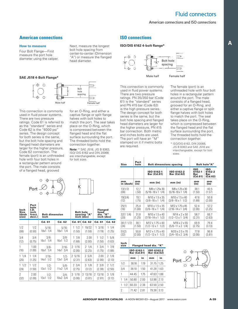
A
AEROQUIP MASTER CATALOG A-HOOV-MC001-E3—August 2017 www.eaton.com A-39
ISO/DIS 6162 4-bolt flange*
This connection is commonly used in fluid power systems. There are two pressure ratings. PN 35/350 bar (Code 61) is the “standard” series and PN 415 bar (Code 62) is the high pressure series. The design concept for both series is the same, but the bolt hole spacing and flanged head diameters are larger for the higher pressure, PN 415 bar connection. Both metric and inches bolts are used. The port will have an “M” stamped on it if metric bolts are required.
The female (port) is an unthreaded hole with four bolt holes in a rectangular pattern around the port. The male consists of a flanged head, grooved for an O-Ring, and either a captive flange or split flange halves with bolt holes to match the port. The seal takes place on the O-Ring, which is compressed between the flanged head and the flat surface surrounding the port. The threaded bolts hold the connection together.* ISO/DIS 6162, DIN 20066,
JIS B 8363 and SAE J518 are interchangeable, except for bolt sizes.
SizePorthole Bolt dimensions spacing Bolt hole“A”
ISO 6162-1Bar (Cd.61)
ISO 6162-2Bar (Cd.62)
ISO 6162-1Bar (Cd.61)
ISO 6162-2Bar (Cd.62)
mmin (dash)
mm (in) mm (in) mm (in) mm
(in)mm (in)
13(1/2)(08)
12,7(.50)
M8 x 1.25x 30(5/16–18 x 1 1/4)
M8 x 1.25 x 30(5/16–18 x 1 1/4)
38.1(1.50)
40.5(1.57)
19(3/4)(12)
19,1(.75)
M10 x 1.5 x 35(3/8–16 x 1 1/4)
M10 x 1.5 x 40(3/8–16 x 1 1/2)
47.6(1.88)
50.8(2.00)
25(1)(16)
25,4(1.00)
M10 x 1.5 x 35(3/8–16 x 1 1/4)
M12 x 1.75 x 45(7/16–14 x 1 3/4)
52.4(2.06)
57.2(2.25)
32(1 1/4)(20)
31,8(1.25)
M10 x 1.5 x 40(7/16–14 x 1 1/2)
M14 x 2 x 50(1/2–13 x 1 3/4)
58.7(2.31)
66.7(2.63)
38 (1 1/2)(24)
38,1(1.50)
M12 x 1.75 x 40(1/2–13 x 1 1/2)
M16 x 2 x 55(5/8–11 x 2 1/4)
69.9(2.75)
79.4(3.13)
51(2)(32)
50,8(2.00)
M12 x 1.75 x 40(1/2–13 x 1 1/2)
M20 x 2.5 x 70(3/4–10 x 2 3/4)
77.8(3.06)
96.8(3.81)
Inchsize Flanged head dia. “K”
ISO 6162-1 Bar (Cd.61)
ISO 6162-2 Bar (Cd.62)
mm in mm in
1/2 30.18 1.19 31.75 1.25
3/4 38.10 1.50 41.28 1.63
1 44.45 1.75 47.63 1.88
1 1/4 50.80 2.00 53.98 2.13
1 1/2 60.33 2.38 63.50 2.50
2 71.42 2.81 79.38 3.13
“A” “K”Bolt holespacing
Female halfMale half
Port A K
Port A K
American connections ISO connections
Fluid connectorsAmerican connections and ISO connections
SAE J518 4-Bolt Flange*
How to measure
Four Bolt Flange—First measure the port hole diameter using the caliper.
Next, measure the longest bolt hole spacing from center-to-center (Dimension “A”) or measure the flanged head diameter.
This connection is commonly used in fluid power systems. There are two pressure ratings. Code 61 is referred to as the “standard” series and Code 62 is the “6000 psi” series. The design concept for both series is the same, but the bolt hole spacing and flanged head diameters are larger for the higher pressure, Code 62 connection. The female (port) is an unthreaded hole with four bolt holes in a rectangular pattern around the port. The male consists of a flanged head, grooved
for an O-Ring, and either a captive flange or split flange halves with bolt holes to match the port. The seal takes place on the O-Ring, which is compressed between the flanged head and the flat surface surrounding the port. The threaded bolts hold the connection together.
ote:N * SAE J518, JIS B 8363, ISO/ DIS 6162 and DIN 20066 are interchangeable, except for bolt sizes.
Male half
A KBoltholespacing
Female half
Port A K
InchSize(dashsize)
PortholeI.D.inchfract.deci.)
Bolt dimension inch
Bolt holespacing “A”inch (dec)
Flangedhead dia. “K”inch (dec)
Cd. 61 Cd. 62 Cd. 61 Cd. 62 Cd. 61 Cd. 62
1/2 1/2 5/16- 18x1 1/4
5/16- 18x1 1/4
1 1/2 1 19/32 1 3/16 1 1/4(08) (0.50) (1.50) (1.59) (1.19) (1.25)
3/4 3/4 3/8- 16x1 1/4
3/8- 16x1 1/2
1 7/8 2.00 1 1/2 1 5/8(12) (0.75) (1.88) (2.00) (1.50) (1.63)
1 1.00 3/8- 16x1 1/4
7/16- 14x1 3/4
2 1/16 2 1/4 1 3/4 1 7/8(16) (1.00) (2.06) (2.25) (1.75) (1.88)
1 1/4 1 1/4 7/16- 14x1 1/2
1/2- 13x1 3/4
2 5/16 2 5/8 2.00 2 1/8(20) (1.25) (2.31) (2.63) (2.00) (2.13)
1 1/2 1 1/2 1/2- 13x1 1/2
5/8- 11x2 1/4
2 3/4 3 1/8 2 3/8 2 1/2(24) (1.50) (2.75) (3.12) (2.38) (2.50)
2 2.00 1/2- 13x1 1/2
3/4- 10x2 3/4
3 1/16 3 13/16 2 13/16 3 1/8(32) (2.00) (3.06) (3.81) (2.81) (3.12)
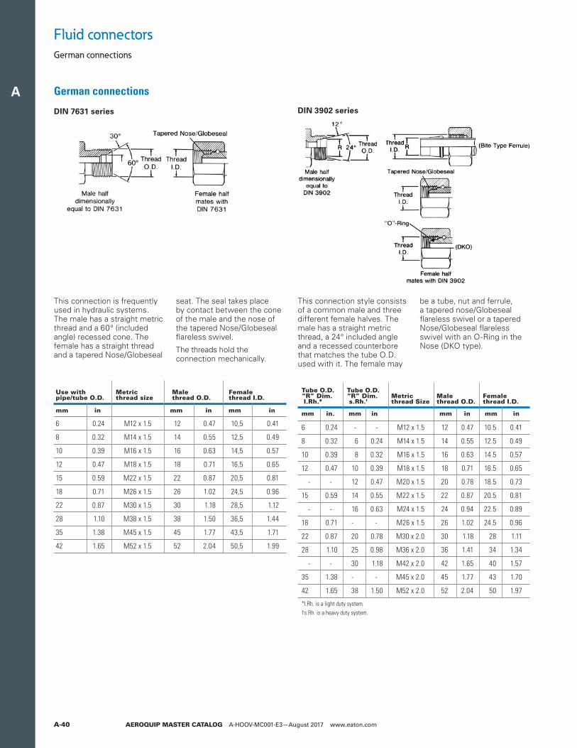
A
AEROQUIP MASTER CATALOG A-HOOV-MC001-E3—August 2017 www.eaton.comA-40
DIN 7631 series
This connection is frequently used in hydraulic systems. The male has a straight metric thread and a 60° (included angle) recessed cone. The female has a straight thread and a tapered Nose/Globeseal
seat. The seal takes place by contact between the cone of the male and the nose of the tapered Nose/Globeseal flareless swivel.
The threads hold the connection mechanically.
Use withpipe/tube O.D.
Metric thread size
Male thread O.D.
Female thread I.D.
mm in mm in mm in
6 0.24 M12 x 1.5 12 0.47 10,5 0.41
8 0.32 M14 x 1.5 14 0.55 12,5 0.49
10 0.39 M16 x 1.5 16 0.63 14,5 0.57
12 0.47 M18 x 1.5 18 0.71 16,5 0.65
15 0.59 M22 x 1.5 22 0.87 20,5 0.81
18 0.71 M26 x 1.5 26 1.02 24,5 0.96
22 0.87 M30 x 1.5 30 1.18 28,5 1.12
28 1.10 M38 x 1.5 38 1.50 36,5 1.44
35 1.38 M45 x 1.5 45 1.77 43,5 1.71
42 1.65 M52 x 1.5 52 2.04 50,5 1.99
Fluid connectorsGerman connections
German connections
DIN 3902 series
This connection style consists of a common male and three different female halves. The male has a straight metric thread, a 24° included angle and a recessed counterbore that matches the tube O.D. used with it. The female may
be a tube, nut and ferrule, a tapered nose/Globeseal flareless swivel or a tapered Nose/Globeseal flareless swivel with an O-Ring in the Nose (DKO type).
Tube O.D.“R” Dim. I.Rh.*
Tube O.D.“R” Dim. s.Rh.†
Metricthread Size
Male thread O.D.
Female thread I.D.
mm in. mm in mm in mm in
6 0.24 - - M12 x 1.5 12 0.47 10.5 0.41
8 0.32 6 0.24 M14 x 1.5 14 0.55 12.5 0.49
10 0.39 8 0.32 M16 x 1.5 16 0.63 14.5 0.57
12 0.47 10 0.39 M18 x 1.5 18 0.71 16.5 0.65
- - 12 0.47 M20 x 1.5 20 0.78 18.5 0.73
15 0.59 14 0.55 M22 x 1.5 22 0.87 20.5 0.81
- - 16 0.63 M24 x 1.5 24 0.94 22.5 0.89
18 0.71 - - M26 x 1.5 26 1.02 24.5 0.96
22 0.87 20 0.78 M30 x 2.0 30 1.18 28 1.11
28 1.10 25 0.98 M36 x 2.0 36 1.41 34 1.34
- - 30 1.18 M42 x 2.0 42 1.65 40 1.57
35 1.38 - - M45 x 2.0 45 1.77 43 1.70
42 1.65 38 1.50 M52 x 2.0 52 2.04 50 1.97
*I.Rh. is a light duty system.†s.Rh. is a heavy duty system.
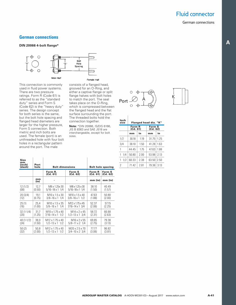
A
AEROQUIP MASTER CATALOG A-HOOV-MC001-E3—August 2017 www.eaton.com A-41
Fluid connectorGerman connections
German connections
DIN 20066 4-bolt flange*
This connection is commonly used in fluid power systems. There are two pressure ratings. Form R (Code 61) is referred to as the “standard duty” series and Form S (Code 62) is the “heavy duty” series. The design concept for both series is the same, but the bolt hole spacing and flanged head diameters are larger for the higher pressure, Form S connection. Both metric and inch bolts are used. The female (port) is an unthreaded hole with four bolt holes in a rectangular pattern around the port. The male
consists of a flanged head, grooved for an O-Ring, and either a captive flange or split flange halves with bolt holes to match the port. The seal takes place on the O-Ring, which is compressed between the flanged head and the flat surface surrounding the port.The threaded bolts hold the connection together.
ote:N *DIN 20066, IS/DIS 6166, JIS B 8363 and SAE J518 are interchangeable, except for bolt sizes.
Sizemm(inch)(dash)
Porthole Bolt dimensions Bolt hole spacing
Form R.(Cd. 61)
Form S(Cd. 62)
Form R(Cd. 61)
Form S(Cd. 62)
mm (in) - - mm (in) mm (in)
12 (1/2)(08)
12,7(0.50)
M8 x 1.25x 305/16–18 x 1 1/4
M8 x 1.25 x 305/16–18 x 1 1/4
38.10(1.50)
40.49(1.57)
20 (3/4)(12)
19,1(0.75)
M10 x 1.5 x 303/8–16 x 1 1/4
M10 x 1.5 x 403/8–16 x 1 1/2
47.63(1.88)
50.80(2.00)
25 (1)(16)
25,4(1.00)
M10 x 1.5 x 353/8–16 x 1 1/4
M12 x 1.75 x 457/16–14 x 1 3/4
52.37(2.06)
57.15(2.25)
32 (1-1/4)(20)
31,7(1.25)
M10 x 1.75 x 407/16–14 x 1 1/2
M14 x 2 x 451/2–13 x 1 3/4
58.72(2.31)
66.68(2.63)
40 (1-1/2)(24)
38,0(1.50)
M12 x 1.75 x 401/2–13 x 1 1/2
M16 x 2 x 555/8–11 x 2 1/4
69.85(2.75)
79.38(3.13)
50 (2)(32)
50,8(2.00)
M12 x 1.75 x 401/2–13 x 1 1/2
M20 x 2.5 x 703/4–10 x 2 3/4
77.77(3.06)
96.82(3.81)
Inchsize Flanged head dia. “K”
Form R(Cd. 61)
Form S(Cd. 62)
mm in mm in
1/2 30.18 1.19 31.75 1.25
3/4 38.10 1.50 41.28 1.63
1 44.45 1.75 47.63 1.88
1 1/4 50.80 2.00 53.98 2.13
1 1/2 60.33 2.38 63.50 2.50
2 71.42 2.81 79.38 3.13
Port A KPort A K
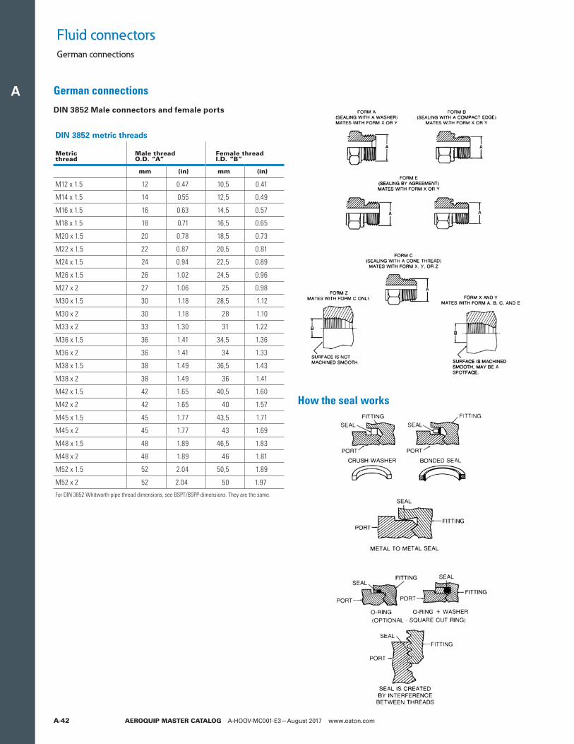
A
AEROQUIP MASTER CATALOG A-HOOV-MC001-E3—August 2017 www.eaton.comA-42
DIN 3852 Male connectors and female ports
DIN 3852 metric threads
Metricthread
Male thread O.D. “A”
Female thread I.D. “B”
mm (in) mm (in)
M12 x 1.5 12 0.47 10,5 0.41
M14 x 1.5 14 0.55 12,5 0.49
M16 x 1.5 16 0.63 14,5 0.57
M18 x 1.5 18 0.71 16,5 0.65
M20 x 1.5 20 0.78 18,5 0.73
M22 x 1.5 22 0.87 20,5 0.81
M24 x 1.5 24 0.94 22,5 0.89
M26 x 1.5 26 1.02 24,5 0.96
M27 x 2 27 1.06 25 0.98
M30 x 1.5 30 1.18 28,5 1.12
M30 x 2 30 1.18 28 1.10
M33 x 2 33 1.30 31 1.22
M36 x 1.5 36 1.41 34,5 1.36
M36 x 2 36 1.41 34 1.33
M38 x 1.5 38 1.49 36,5 1.43
M38 x 2 38 1.49 36 1.41
M42 x 1.5 42 1.65 40,5 1.60
M42 x 2 42 1.65 40 1.57
M45 x 1.5 45 1.77 43,5 1.71
M45 x 2 45 1.77 43 1.69
M48 x 1.5 48 1.89 46,5 1.83
M48 x 2 48 1.89 46 1.81
M52 x 1.5 52 2.04 50,5 1.89
M52 x 2 52 2.04 50 1.97
For DIN 3852 Whitworth pipe thread dimensions, see BSPT/BSPP dimensions. They are the same.
German connections
How the seal works
Fluid connectorsGerman connections
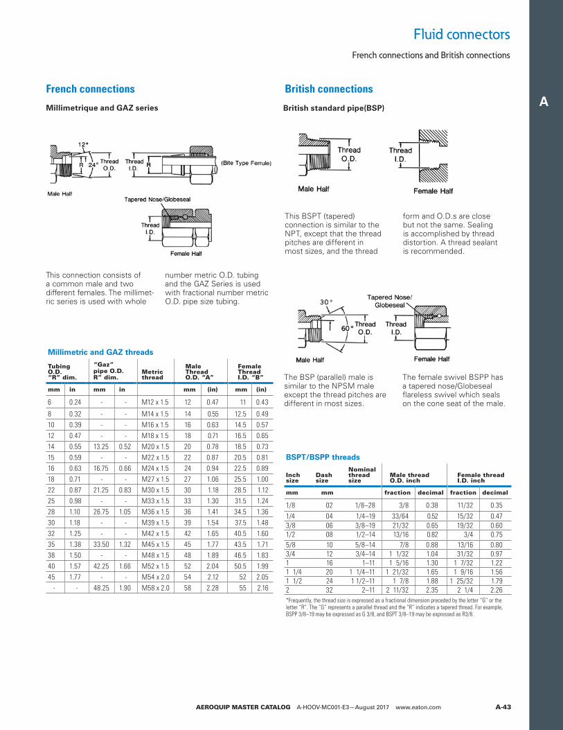
A
AEROQUIP MASTER CATALOG A-HOOV-MC001-E3—August 2017 www.eaton.com A-43
BSPT/BSPP threads
Inchsize
Dashsize
Nominalthreadsize
Male threadO.D. inch
Female threadI.D. inch
mm mm fraction decimal fraction decimal
1/8 02 1/8–28 3/8 0.38 11/32 0.351/4 04 1/4–19 33/64 0.52 15/32 0.473/8 06 3/8–19 21/32 0.65 19/32 0.601/2 08 1/2–14 13/16 0.82 3/4 0.755/8 10 5/8–14 7/8 0.88 13/16 0.803/4 12 3/4–14 1 1/32 1.04 31/32 0.971 16 1–11 1 5/16 1.30 1 7/32 1.221 1/4 20 1 1/4–11 1 21/32 1.65 1 9/16 1.561 1/2 24 1 1/2–11 1 7/8 1.88 1 25/32 1.792 32 2–11 2 11/32 2.35 2 1/4 2.26*Frequently, the thread size is expressed as a fractional dimension preceded by the letter “G” or the letter “R”. The “G” represents a parallel thread and the “R” indicates a tapered thread. For example, BSPP 3/8–19 may be expressed as G 3/8, and BSPT 3/8–19 may be expressed as R3/8.
British connections
British standard pipe(BSP)
This BSPT (tapered) connection is similar to the NPT, except that the thread pitches are different in most sizes, and the thread
form and O.D.s are close but not the same. Sealing is accomplished by thread distortion. A thread sealant is recommended.
The BSP (parallel) male is similar to the NPSM male except the thread pitches are different in most sizes.
The female swivel BSPP has a tapered nose/Globeseal flareless swivel which seals on the cone seat of the male.
Millimetric and GAZ threads
TubingO.D.“R” dim.
“Gaz”pipe O.D. R” dim.
Metricthread
Male Thread O.D. “A”
Female Thread I.D. “B”
mm in mm in mm (in) mm (in)
6 0.24 - - M12 x 1.5 12 0.47 11 0.43
8 0.32 - - M14 x 1.5 14 0.55 12.5 0.4910 0.39 - - M16 x 1.5 16 0.63 14.5 0.5712 0.47 - - M18 x 1.5 18 0.71 16.5 0.6514 0.55 13.25 0.52 M20 x 1.5 20 0.78 18.5 0.7315 0.59 - - M22 x 1.5 22 0.87 20.5 0.8116 0.63 16.75 0.66 M24 x 1.5 24 0.94 22.5 0.8918 0.71 - - M27 x 1.5 27 1.06 25.5 1.0022 0.87 21.25 0.83 M30 x 1.5 30 1.18 28.5 1.1225 0.98 - - M33 x 1.5 33 1.30 31.5 1.2428 1.10 26.75 1.05 M36 x 1.5 36 1.41 34.5 1.3630 1.18 - - M39 x 1.5 39 1.54 37.5 1.4832 1.25 - - M42 x 1.5 42 1.65 40.5 1.6035 1.38 33.50 1.32 M45 x 1.5 45 1.77 43.5 1.7138 1.50 - - M48 x 1.5 48 1.89 46.5 1.8340 1.57 42.25 1.66 M52 x 1.5 52 2.04 50.5 1.9945 1.77 - - M54 x 2.0 54 2.12 52 2.05
- - 48.25 1.90 M58 x 2.0 58 2.28 55 2.16
French connections
Millimetrique and GAZ series
This connection consists of a common male and two different females. The millimet-ric series is used with whole
number metric O.D. tubing and the GAZ Series is used with fractional number metric O.D. pipe size tubing.
Fluid connectorsFrench connections and British connections
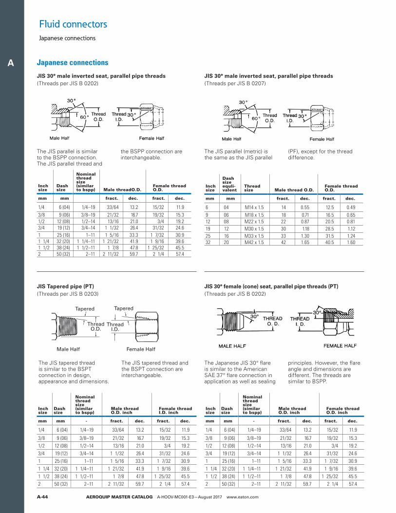
A
AEROQUIP MASTER CATALOG A-HOOV-MC001-E3—August 2017 www.eaton.comA-44
Japanese connections
JIS 30° male inverted seat, parallel pipe threads(Threads per JIS B 0202)
JIS 30° male inverted seat, parallel pipe threads(Threads per JIS B 0207)
JIS Tapered pipe (PT)(Threads per JIS B 0203)
JIS 30° female (cone) seat, parallel pipe threads (PT)(Threads per JIS B 0202)
The JIS parallel is similar to the BSPP connection. The JIS parallel thread and
the BSPP connection are interchangeable.
The JIS parallel (metric) is the same as the JIS parallel
(PF), except for the thread difference.
The JIS tapered thread is similar to the BSPT connection in design, appearance and dimensions.
The JIS tapered thread and the BSPT connection are interchangeable.
The Japanese JIS 30° flare is similar to the American SAE 37° flare connection in application as well as sealing
principles. However, the flare angle and dimensions are different. The threads are similar to BSPP.
Inchsize
Dashsize
Nominalthreadsize (similarto bspp) Male threadO.D.
Female thread O.D.
mm mm fract. dec. fract. dec.
1/4 6 (04) 1/4–19 33/64 13.2 15/32 11.93/8 9 (06) 3/8–19 21/32 16.7 19/32 15.31/2 12 (08) 1/2–14 13/16 21.0 3/4 19.23/4 19 (12) 3/4–14 1 1/32 26.4 31/32 24.61 25 (16) 1–11 1 5/16 33.3 1 7/32 30.91 1/4 32 (20) 1 1/4–11 1 21/32 41.9 1 9/16 39.61 1/2 38 (24) 1 1/2–11 1 7/8 47.8 1 25/32 45.52 50 (32) 2–11 2 11/32 59.7 2 1/4 57.4
Inchsize
Dashsizeequli-valent
Threadsize Male thread O.D.
Female threadO.D.
mm mm fract. dec. fract. dec.
6 04 M14 x 1.5 14 0.55 12.5 0.499 06 M18 x 1.5 18 0.71 16.5 0.6512 08 M22 x 1.5 22 0.87 20.5 0.8119 12 M30 x 1.5 30 1.18 28.5 1.1225 16 M33 x 1.5 33 1.30 31.5 1.2432 20 M42 x 1.5 42 1.65 40.5 1.60
Inchsize
Dashsize
Nominalthreadsize (similarto bspp)
Male threadO.D. inch
Female threadI.D. inch
mm mm - fract. dec. fract. dec.
1/4 6 (04) 1/4–19 33/64 13.2 15/32 11.9
3/8 9 (06) 3/8–19 21/32 16.7 19/32 15.31/2 12 (08) 1/2–14 13/16 21.0 3/4 19.23/4 19 (12) 3/4–14 1 1/32 26.4 31/32 24.61 25 (16) 1–11 1 5/16 33.3 1 7/32 30.91 1/4 32 (20) 1 1/4–11 1 21/32 41.9 1 9/16 39.61 1/2 38 (24) 1 1/2–11 1 7/8 47.8 1 25/32 45.52 50 (32) 2–11 2 11/32 59.7 2 1/4 57.4
Inchsize
Dashsize
Nominalthreadsize (similarto bspp)
Male threadO.D. inch
Female threadO.D. inch
mm mm - fract. dec. fract. dec.
1/4 6 (04) 1/4–19 33/64 13.2 15/32 11.9
3/8 9 (06) 3/8–19 21/32 16.7 19/32 15.31/2 12 (08) 1/2–14 13/16 21.0 3/4 19.23/4 19 (12) 3/4–14 1 1/32 26.4 31/32 24.61 25 (16) 1–11 1 5/16 33.3 1 7/32 30.91 1/4 32 (20) 1 1/4–11 1 21/32 41.9 1 9/16 39.61 1/2 38 (24) 1 1/2–11 1 7/8 47.8 1 25/32 45.52 50 (32) 2–11 2 11/32 59.7 2 1/4 57.4
Fluid connectorsJapanese connections
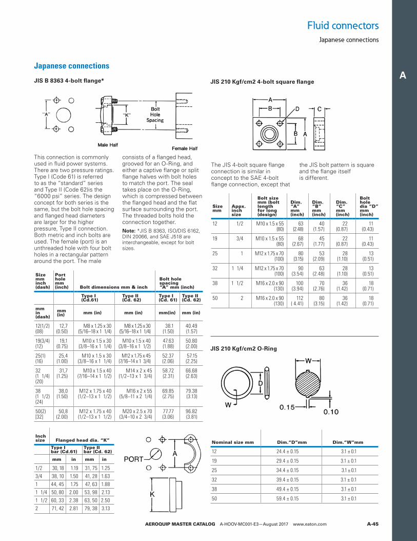
A
AEROQUIP MASTER CATALOG A-HOOV-MC001-E3—August 2017 www.eaton.com A-45
JIS B 8363 4-bolt flange*
Japanese connections
JIS 210 Kgf/cm2 4-bolt square flange
This connection is commonly used in fluid power systems. There are two pressure ratings. Type I (Code 61) is referred to as the “standard” series and Type II (Code 62)is the “6000 psi” series. The design concept for both series is the same, but the bolt hole spacing and flanged head diameters are larger for the higher pressure, Type II connection. Both metric and inch bolts are used. The female (port) is an unthreaded hole with four bolt holes in a rectangular pattern around the port. The male
consists of a flanged head, grooved for an O-Ring, and either a captive flange or split flange halves with bolt holes to match the port. The seal takes place on the O-Ring, which is compressed between the flanged head and the flat surface surrounding the port. The threaded bolts hold the connection together.
ote:N *JIS B 8363, ISO/DIS 6162, DIN 20066, and SAE J518 are interchangeable, except for bolt sizes.
The JIS 4-bolt square flange connection is similar in concept to the SAE 4-bolt flange connection, except that
the JIS bolt pattern is square and the flange itself is different.
Sizemminch(dash)
Portholemm(inch) Bolt dimensions mm & inch
Bolt hole spacing“A” mm (inch)
Type I(Cd.61)
Type II(Cd. 62)
Type I(Cd. 61)
Type II(Cd. 62)
mmin (dash)
mm (in) mm (in) mm (in) mm(in) mm (in)
12(1/2)(08)
12,7(0.50)
M8 x 1.25 x 30(5/16–18 x 1 1/4)
M8 x 1.25 x 30(5/16–18 x 1 1/4)
38.1(1.50)
40.49(1.57)
19(3/4)(12)
19,1(0.75)
M10 x 1.5 x 30(3/8–16 x 1 1/4)
M10 x 1.5 x 40(3/8–16 x 1 1/2)
47.63(1.88)
50.80(2.00)
25(1)(16)
25,4(1.00)
M10 x 1.5 x 30(3/8–16 x 1 1/4)
M12 x 1.75 x 45(7/16–14 x 1 3/4)
52.37(2.06)
57.15(2.25)
32 (1 1/4)(20)
31,7(1.25)
M10 x 1.5 x 40(7/16–14 x 1 1/2)
M14 x 2 x 45(1/2–13 x 1 3/4)
58.72(2.31)
66.68(2.63)
38 (1 1/2)(24)
38,0(1.50)
M12 x 1.75 x 40(1/2–13 x 1 1/2)
M16 x 2 x 55(5/8–11 x 2 1/4)
69.85(2.75)
79.38(3.13)
50(2)[32]
50,8(2.00)
M12 x 1.75 x 40(1/2–13 x 1 1/2)
M20 x 2.5 x 70(3/4–10 x 2 3/4)
77.77(3.06)
96.82(3.81)
Sizemm
Appx.inchsize
Bolt sizemm (boltlengthfor long(design)
Dim.“A”mm(inch)
Dim.“B”mm(inch)
Dim.“C”mm(inch)
Boltholedia “D”mm(inch)
12 1/2 M10 x 1.5 x 55(80)
63(2.48)
40(1.57)
22(0.87)
11(0.43)
19 3/4 M10 x 1.5 x 55(80)
68(2.67)
45(1.77)
22(0.87)
11(0.43)
25 1 M12 x 1.75 x 70(100)
80(3.15)
53(2.09)
28(1.10)
13(0.51)
32 1 1/4 M12 x 1.75 x 70(100)
90(3.54)
63(2.48)
28(1.10)
13(0.51)
38 1 1/2 M16 x 2.0 x 90(130)
100(3.94)
70(2.76)
36(1.42)
18(0.71)
50 2 M16 x 2.0 x 90(130)
112( 4.41)
80(3.15)
36(1.42)
18(0.71)
Nominal size mm Dim.“D”mm Dim.“W”mm
12 24.4 ± 0.15 3.1 ± 0.1
19 29.4 ± 0.15 3.1 ± 0.1
25 34.4 ± 0.15 3.1 ± 0.1
32 39.4 ± 0.15 3.1 ± 0.1
38 49.4 ± 0.15 3.1 ± 0.1
50 59.4 ± 0.15 3.1 ± 0.1
Inchsize Flanged head dia. “K”
Type Ibar (Cd.61)
Type IIbar (Cd. 62)
mm in mm in
1/2 30, 18 1.19 31, 75 1.253/4 38, 10 1.50 41, 28 1.631 44, 45 1.75 47, 63 1.881 1/4 50, 80 2.00 53, 98 2.131 1/2 60, 33 2.38 63, 50 2.502 71, 42 2.81 79, 38 3.13
JIS 210 Kgf/cm2 O-Ring
Fluid connectorsJapanese connections
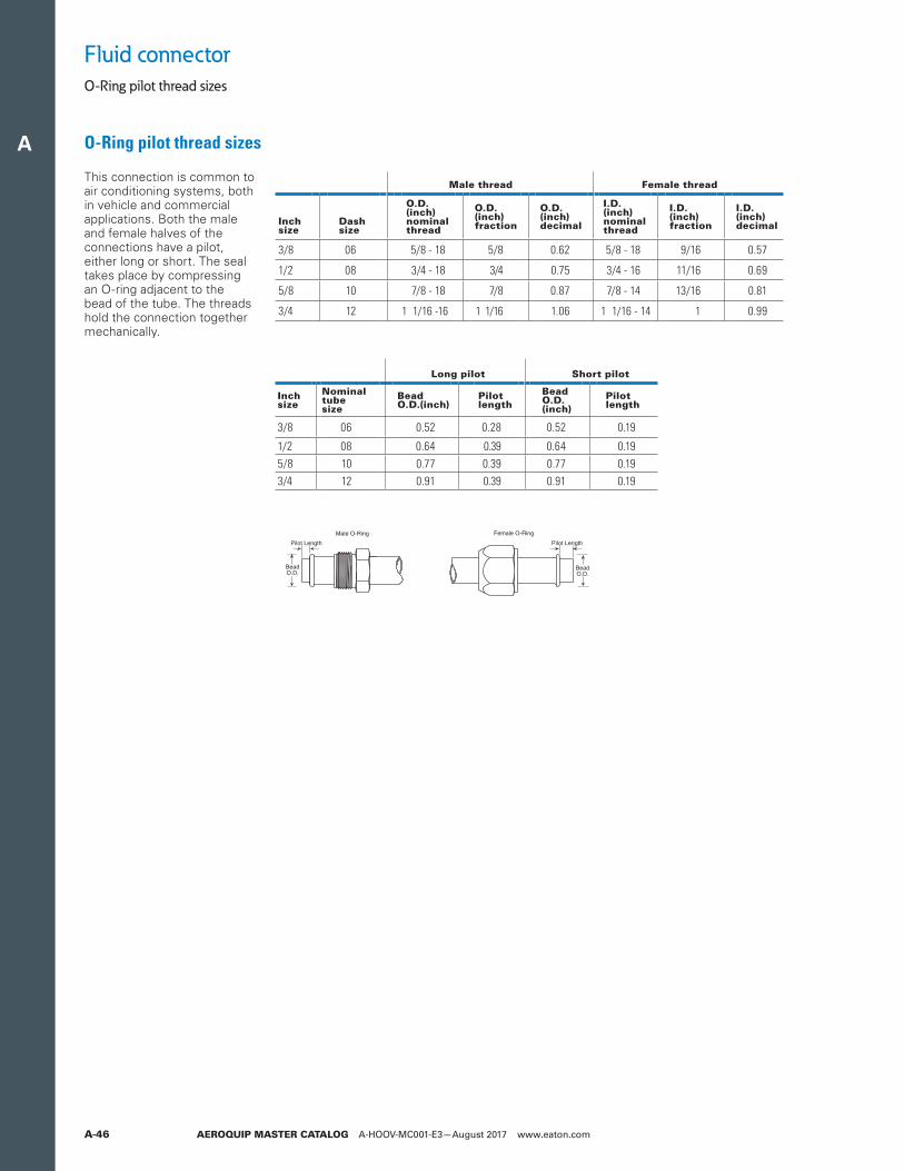
A
AEROQUIP MASTER CATALOG A-HOOV-MC001-E3—August 2017 www.eaton.comA-46
O-Ring pilot thread sizes
O-Ring pilot thread sizes
Fluid connector
This connection is common to air conditioning systems, both in vehicle and commercial applications. Both the male and female halves of the connections have a pilot, either long or short. The seal takes place by compressing an O-ring adjacent to the bead of the tube. The threads hold the connection together mechanically.
Male thread Female thread
Inchsize
Dashsize
O.D. (inch)nominalthread
O.D. (inch)fraction
O.D. (inch)decimal
I.D. (inch)nominalthread
I.D. (inch)fraction
I.D. (inch)decimal
3/8 06 5/8 - 18 5/8 0.62 5/8 - 18 9/16 0.57
1/2 08 3/4 - 18 3/4 0.75 3/4 - 16 11/16 0.69
5/8 10 7/8 - 18 7/8 0.87 7/8 - 14 13/16 0.81
3/4 12 1 1/16 -16 1 1/16 1.06 1 1/16 - 14 1 0.99
Long pilot Short pilot
Inchsize
Nominaltubesize
Bead O.D.(inch)
Pilotlength
Bead O.D.(inch)
Pilotlength
3/8 06 0.52 0.28 0.52 0.19
1/2 08 0.64 0.39 0.64 0.195/8 10 0.77 0.39 0.77 0.193/4 12 0.91 0.39 0.91 0.19
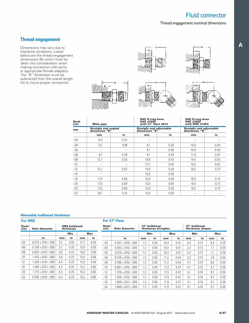
A
AEROQUIP MASTER CATALOG A-HOOV-MC001-E3—August 2017 www.eaton.com A-47
Fluid connectorThread engagement nominal dimensions
Thread engagement
Dimensions may vary due to tolerance conditions. Listed below are the thread engagement dimensions (B) which must be taken into consideration when making connection with ports or appropriate female adapters. The “B” dimension must be subtracted from the overall length (A) to insure proper connection.
Dashsize Male pipe
SAE O-ring bossSAE J1926with 37° flare J514
SAE O-ring bossSAE J1926with ORS J1453
mm Straight and angleddimension “B”
Straight and adjustabledimension “B”
Straight and adjustabledimension “B”
mm in mm in mm in
–02 6,4 0.25 – – – –
–04 9,7 0.38 9,1 0.36 10,9 0.43–05 – – 9,1 0.36 10,9 0.43–06 9,7 0.38 9,1 0.39 11,9 0.47–08 12,7 0.50 10,9 0.43 14,0 0.55–10 – – 12,7 0.50 16,0 0.63–12 15,7 0.62 15,0 0.59 18,5 0.73–14 – – 15,0 0.59 – ––16 17,5 0.69 15,0 0.59 18,5 0.73–20 17,5 0.69 15,0 0.59 18,5 0.73–24 17,5 0.69 15,0 0.59 18,5 0.73–32 19,1 0.75 15,0 0.59 – –
For ORS
Dashsize Hole diameter
ORS bulkhead thickness
Min Max
in mm in mm in
–04 0.575 +.015/–.000 5,1 0.20 12,7 0.50–06 0.700 +.015/–.000 5,1 0.20 15,0 0.59–08 0.825 +.015/–.000 5,6 0.22 15,0 0.59–10 1.015 +.015/–.000 5,8 0.23 15,0 0.59–12 1.200 +.015/–.000 6,4 0.25 15,0 0.59
–16 1.450 +.015/–.000 6,4 0.25 15,2 0.60–20 1.715 +.015/–.000 6,4 0.25 15,2 0.60
–24 2.030 +.015/–.000 6,4 0.25 15,2 0.60
For 37° Flare
Dash size Hole diameter
37° bulkhead thickness straights
37° bulkhead thickness shapes
Min Max Min Max
in mm in mm in mm in mm in
–03 0.391 +.016/–.000 1,3 0.05 10,4 0.41 3,3 0.13 6,4 0.25–04 0.453 +.016/–.000 1,3 0.05 10,4 0.41 3,3 0.13 7,1 0.28–05 0.516 +.016/–.000 1,3 0.05 10,4 0.41 3,3 0.13 7,1 0.28–06 0.578 +.016/–.000 1,3 0.05 11,2 0.44 3,3 0.13 7,6 0.30–08 0.766 +.016/–.000 1,3 0.05 11,2 0.44 4,1 0.16 8,6 0.34–10 0.891 +.016/–.000 1,3 0.05 11,9 0.47 4,1 0.16 9,1 0.36–12 1.076 +.016/–.000 1,3 0.05 11,9 0.47 4,1 0.16 9,7 0.38–16 1.328 +.016/–.000 1,3 0.05 11,9 0.47 4,1 0.16 9,7 0.38–20 1.656 +.031/–.000 1,3 0.05 11,9 0.47 4,1 0.16 9,7 0.38–24 1.906 +.031/–.000 1,3 0.05 11,9 0.47 4,1 0.16 9,7 0.38
Allowable bulkhead thickness:
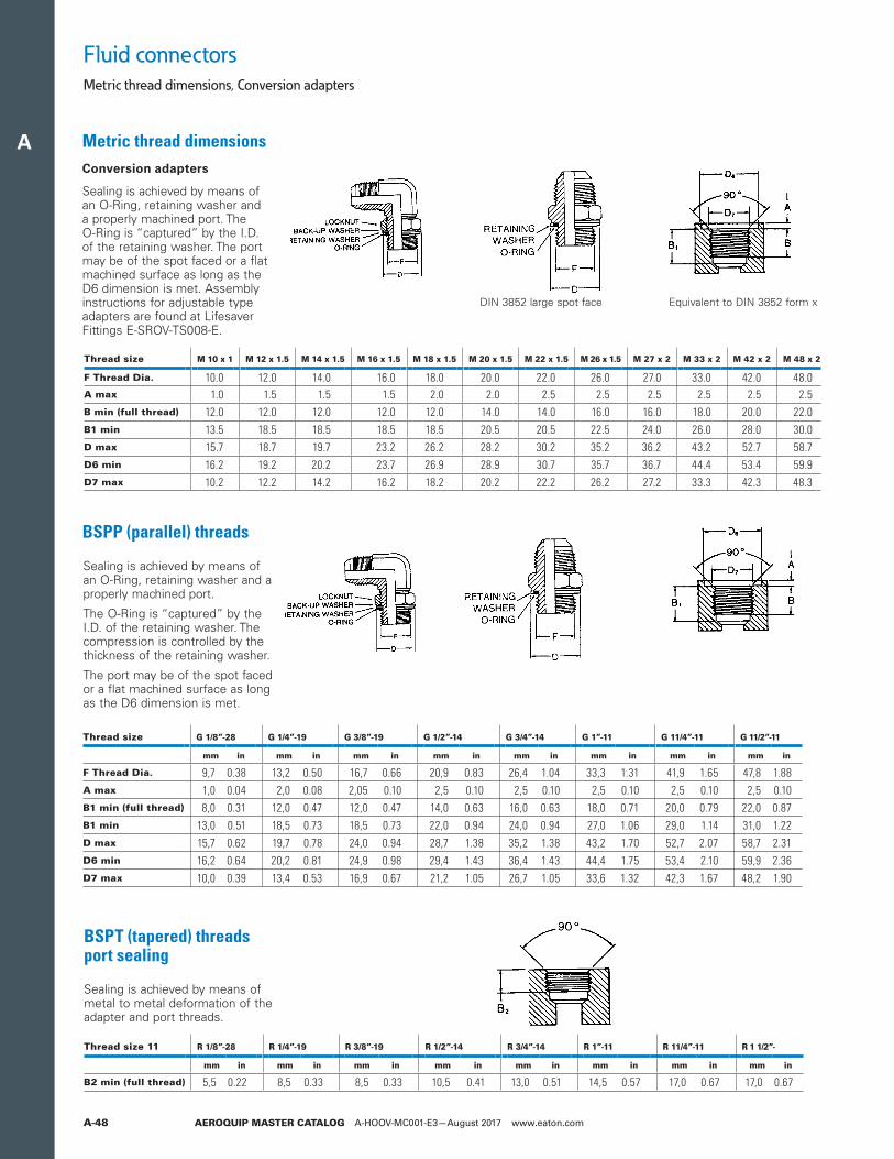
A
AEROQUIP MASTER CATALOG A-HOOV-MC001-E3—August 2017 www.eaton.comA-48
Fluid connectorsMetric thread dimensions, Conversion adapters
BSPT (tapered) threads port sealing
Sealing is achieved by means of metal to metal deformation of the adapter and port threads.
Thread size 11 R 1/8”-28 R 1/4”-19 R 3/8”-19 R 1/2”-14 R 3/4”-14 R 1”-11 R 11/4”-11 R 1 1/2”-
mm in mm in mm in mm in mm in mm in mm in mm in
B2 min (full thread) 5,5 0.22 8,5 0.33 8,5 0.33 10,5 0.41 13,0 0.51 14,5 0.57 17,0 0.67 17,0 0.67
Thread size G 1/8”-28 G 1/4”-19 G 3/8”-19 G 1/2”-14 G 3/4”-14 G 1”-11 G 11/4”-11 G 11/2”-11
mm in mm in mm in mm in mm in mm in mm in mm in
F Thread Dia. 9,7 0.38 13,2 0.50 16,7 0.66 20,9 0.83 26,4 1.04 33,3 1.31 41,9 1.65 47,8 1.88A max 1,0 0.04 2,0 0.08 2,05 0.10 2,5 0.10 2,5 0.10 2,5 0.10 2,5 0.10 2,5 0.10B1 min (full thread) 8,0 0.31 12,0 0.47 12,0 0.47 14,0 0.63 16,0 0.63 18,0 0.71 20,0 0.79 22,0 0.87B1 min 13,0 0.51 18,5 0.73 18,5 0.73 22,0 0.94 24,0 0.94 27,0 1.06 29,0 1.14 31,0 1.22D max 15,7 0.62 19,7 0.78 24,0 0.94 28,7 1.38 35,2 1.38 43,2 1.70 52,7 2.07 58,7 2.31D6 min 16,2 0.64 20,2 0.81 24,9 0.98 29,4 1.43 36,4 1.43 44,4 1.75 53,4 2.10 59,9 2.36D7 max 10,0 0.39 13,4 0.53 16,9 0.67 21,2 1.05 26,7 1.05 33,6 1.32 42,3 1.67 48,2 1.90
BSPP (parallel) threads
Sealing is achieved by means of an O-Ring, retaining washer and a properly machined port.
The O-Ring is “captured” by the I.D. of the retaining washer. The compression is controlled by the thickness of the retaining washer.
The port may be of the spot faced or a flat machined surface as long as the D6 dimension is met.
Metric thread dimensions Conversion adapters
Sealing is achieved by means of an O-Ring, retaining washer and a properly machined port. The O-Ring is “captured” by the I.D. of the retaining washer. The port may be of the spot faced or a flat machined surface as long as the D6 dimension is met. Assembly instructions for adjustable type adapters are found at Lifesaver Fittings E-SROV-TS008-E.
Equivalent to DIN 3852 form xDIN 3852 large spot face
Thread size M 10 x 1 M 12 x 1.5 M 14 x 1.5 M 16 x 1.5 M 18 x 1.5 M 20 x 1.5 M 22 x 1.5 M 26 x 1.5 M 27 x 2 M 33 x 2 M 42 x 2 M 48 x 2
F Thread Dia. 10.0 12.0 14.0 16.0 18.0 20.0 22.0 26.0 27.0 33.0 42.0 48.0A max 1.0 1.5 1.5 1.5 2.0 2.0 2.5 2.5 2.5 2.5 2.5 2.5B min (full thread) 12.0 12.0 12.0 12.0 12.0 14.0 14.0 16.0 16.0 18.0 20.0 22.0B1 min 13.5 18.5 18.5 18.5 18.5 20.5 20.5 22.5 24.0 26.0 28.0 30.0D max 15.7 18.7 19.7 23.2 26.2 28.2 30.2 35.2 36.2 43.2 52.7 58.7D6 min 16.2 19.2 20.2 23.7 26.9 28.9 30.7 35.7 36.7 44.4 53.4 59.9D7 max 10.2 12.2 14.2 16.2 18.2 20.2 22.2 26.2 27.2 33.3 42.3 48.3
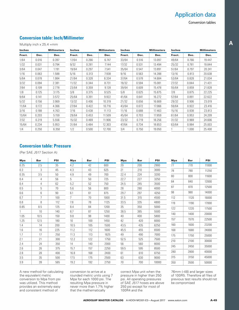
A
AEROQUIP MASTER CATALOG A-HOOV-MC001-E3—August 2017 www.eaton.com A-49
Application dataConversion tables
Conversion table: Inch/Millimeter Multiply inch x 25.4 =mm
Conversion table: Pressure(Per SAE J517 Section A)
Inches Millimeters
Fract. Dec. Dec.
1/64 0.016 0.3971/32 0.031 0.7943/64 0.047 1.1911/16 0.063 1.5885/64 0.078 1.9843/32 0.094 2.3817/64 0.109 2.7781/8 0.125 3.1759/64 0.141 3.5725/32 0.156 3.96911/64 0.172 4.3663/16 0.188 4.76313/64 0.203 5.1597/32 0.219 5.55615/64 0.234 5.9531/4 0.250 6.350
Mpa Bar PSI
0.25 2.5 350.3 3 450.35 3.5 500.4 4 560.4 4 620.5 5 700.6 6 900.7 7 1000.8 8 1120.85 8.5 1251 10 1401.05 10.5 1501.25 12.5 1801.4 14 2001.6 16 2251.7 17 2502.1 21 3002.4 24 3502.6 26 3752.8 28 4003.5 35 5003.9 39 565
Mpa Bar PSI
4.2 42 6004.3 43 6254.9 49 7005 50 7255.2 52 7505.6 56 8006.1 61 8757 70 10007.8 78 11258.4 84 12008.7 87 12509.8 98 140010 100 145010.5 105 150011.2 112 160011.3 113 162512.2 122 175014 140 200015.7 157 225016.8 168 240017.5 175 250019.2 192 2750
Mpa Bar PSI
20 200 290021 210 300022.4 224 320022.7 227 325024.5 245 350028 280 400029.7 297 425031.5 315 450033.5 335 480035 350 500038.5 385 550040 400 580042 420 600043.5 435 625045.5 455 650049 490 700052.5 525 750056 560 800059.5 595 850061 610 875063 630 900070 700 10000
Mpa Bar PSI
77 770 11000
78 780 11250
80 800 11600
84 840 12000
87 870 12500
98 980 14000
112 1120 16000
119 1190 17000
122 1220 17500
140 1400 20000
157 1570 22500
160 1600 23200
168 1680 24000
175 1750 25000
210 2100 30000
245 2450 35000
280 2800 40000
315 3150 45000
350 3500 50000
Inches Millimeters
Fract. Dec. Dec.
17/64 0.266 6.7479/32 0.281 7.14419/64 0.297 7.5415/16 0.313 7.93821/64 0.328 8.33411/32 0.344 8.73123/64 0.359 9.1283/8 0.375 9.52525/64 0.391 9.92213/32 0.406 10.31927/64 0.422 10.7167/16 0.438 11.11329/64 0.453 11.50915/32 0.469 11.90631/64 0.484 12.3031/2 0.500 12.700
Inches Millimeters
Fract. Dec. Dec.
33/64 0.516 13.09717/32 0.531 13.49435/64 0.547 13.8919/16 0.563 14.28837/64 0.578 14.68419/32 0.594 15.08139/64 0.609 15.4785/8 0.625 15.87541/64 0.641 16.27221/32 0.656 16.66943/64 0.672 17.06611/16 0.688 17.46345/64 0.703 17.85923/32 0.719 18.25647/64 0.734 18.6533/4 0.750 19.050
Inches Millimeters
Fract. Dec. Dec.
49/64 0.766 19.44725/32 0.781 19.84451/64 0.797 20.24113/16 0.813 20.63853/64 0.828 21.03427/32 0.844 21.43155/64 0.859 21.8287/8 0.875 22.22557/64 0.891 22.62229/32 0.906 23.01959/64 0.922 23.41615/16 0.938 23.81361/64 0.953 24.20931/32 0.969 24.60663/64 0.984 25.0031 1.000 25.400
A new method for calculating the equivalent metric conversion to Mpa from psi was utilized. This method provides an extremely easy and consistent method of
conversion to arrive at a rounded metric units using 7 Mpa for each 1000 psi. The resulting Mpa pressure in never more than 1.7% higher that the mathematically
correct Mpa unit when the pressure in higher than 250 psi. All operating pressures of SAE J517 hoses are above 250 psi except for most of 100R4 and the
76mm (-48) and larger sizes of 100R5. Therefore all files of previous test results should not be compromised
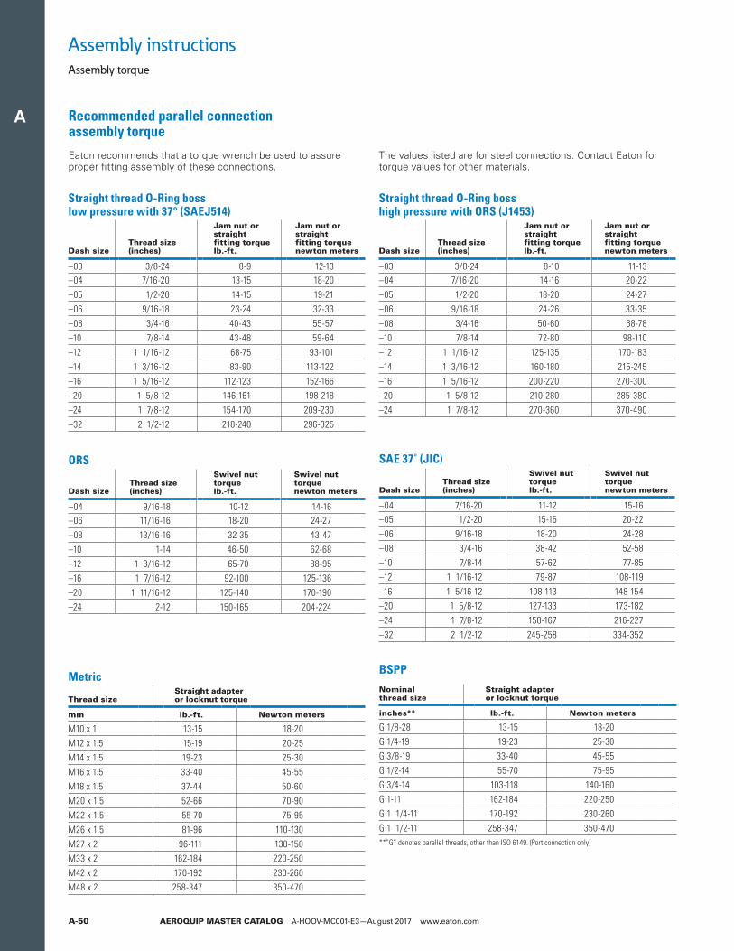
A
AEROQUIP MASTER CATALOG A-HOOV-MC001-E3—August 2017 www.eaton.comA-50
Eaton recommends that a torque wrench be used to assure proper fitting assembly of these connections.
Assembly instructions
Recommended parallel connection assembly torque
Assembly torque
Metric
Thread sizeStraight adapter or locknut torque
mm lb.-ft. Newton meters
M10 x 1 13-15 18-20M12 x 1.5 15-19 20-25M14 x 1.5 19-23 25-30M16 x 1.5 33-40 45-55M18 x 1.5 37-44 50-60M20 x 1.5 52-66 70-90M22 x 1.5 55-70 75-95M26 x 1.5 81-96 110-130M27 x 2 96-111 130-150M33 x 2 162-184 220-250M42 x 2 170-192 230-260M48 x 2 258-347 350-470
BSPP
Nominal thread size
Straight adapter or locknut torque
inches** lb.-ft. Newton meters
G 1/8-28 13-15 18-20G 1/4-19 19-23 25-30G 3/8-19 33-40 45-55G 1/2-14 55-70 75-95G 3/4-14 103-118 140-160G 1-11 162-184 220-250G 1 1/4-11 170-192 230-260G 1 1/2-11 258-347 350-470**”G” denotes parallel threads, other than ISO 6149. (Port connection only)
ORS
Dash sizeThread size(inches)
Swivel nuttorquelb.-ft.
Swivel nuttorquenewton meters
–04 9/16-18 10-12 14-16–06 11/16-16 18-20 24-27–08 13/16-16 32-35 43-47–10 1-14 46-50 62-68–12 1 3/16-12 65-70 88-95–16 1 7/16-12 92-100 125-136–20 1 11/16-12 125-140 170-190–24 2-12 150-165 204-224
SAE 37˚ (JIC)
Dash sizeThread size(inches)
Swivel nuttorquelb.-ft.
Swivel nuttorquenewton meters
–04 7/16-20 11-12 15-16–05 1/2-20 15-16 20-22–06 9/16-18 18-20 24-28–08 3/4-16 38-42 52-58–10 7/8-14 57-62 77-85–12 1 1/16-12 79-87 108-119–16 1 5/16-12 108-113 148-154–20 1 5/8-12 127-133 173-182–24 1 7/8-12 158-167 216-227–32 2 1/2-12 245-258 334-352
Straight thread O-Ring boss low pressure with 37° (SAEJ514)
Dash sizeThread size(inches)
Jam nut orstraightfitting torquelb.-ft.
Jam nut orstraightfitting torquenewton meters
–03 3/8-24 8-9 12-13–04 7/16-20 13-15 18-20–05 1/2-20 14-15 19-21–06 9/16-18 23-24 32-33–08 3/4-16 40-43 55-57–10 7/8-14 43-48 59-64–12 1 1/16-12 68-75 93-101–14 1 3/16-12 83-90 113-122–16 1 5/16-12 112-123 152-166–20 1 5/8-12 146-161 198-218–24 1 7/8-12 154-170 209-230–32 2 1/2-12 218-240 296-325
Straight thread O-Ring boss high pressure with ORS (J1453)
Dash sizeThread size(inches)
Jam nut orstraightfitting torquelb.-ft.
Jam nut orstraightfitting torquenewton meters
–03 3/8-24 8-10 11-13–04 7/16-20 14-16 20-22–05 1/2-20 18-20 24-27–06 9/16-18 24-26 33-35–08 3/4-16 50-60 68-78–10 7/8-14 72-80 98-110–12 1 1/16-12 125-135 170-183–14 1 3/16-12 160-180 215-245–16 1 5/16-12 200-220 270-300–20 1 5/8-12 210-280 285-380–24 1 7/8-12 270-360 370-490
The values listed are for steel connections. Contact Eaton for torque values for other materials.
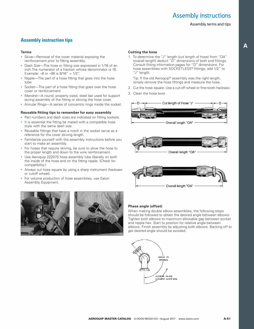
A
AEROQUIP MASTER CATALOG A-HOOV-MC001-E3—August 2017 www.eaton.com A-51
Assembly instruction tips
Terms• Skive—Removal of the cover material exposing the
reinforcement prior to fitting assembly.• Dash Size—The hose or fitting size expressed in 1/16 of an
inch.The numerator of a fraction whose denominator is 16. Example: –8 or –08 is 8/16” = 1/2”.
• Nipple—The part of a hose fitting that goes into the hose tube.
• Socket—The part of a hose fitting that goes over the hose cover or reinforcement.
• Mandrel—A round, properly sized, steel bar used for support during assembly of the fitting or skiving the hose cover.
• Annular Rings—A series of concentric rings inside the socket.
Reusable fitting tips to remember for easy assembly• Part numbers and dash sizes are indicated on fitting sockets.• It is essential the fitting be mated with a compatible hose
style with the same dash size. • Reusable fittings that have a notch in the socket serve as a
reference for the cover skiving length.• Familiarize yourself with the assembly instructions before you
start to make an assembly.• For hoses that require skiving, be sure to skive the hose to
the proper length and down to the wire reinforcement.• Use Aeroquip 222070 hose assembly lube liberally on both
the inside of the hose and on the fitting nipple. (Check for compatibility.)
• Always cut hose square by using a sharp instrument (hacksaw or cutoff wheel).
• For volume production of hose assemblies, use Eaton Assembly Equipment.
Cutting the hose1. To determine the “J” length (cut length of hose) from “OA”
(overall length) de duct “D” dimensions of both end fittings. Consult fitting information pages for “D” dimensions. For hose assemblies with SOCKETLESS® fittings, add 1/2” to “J” length.
Tip: If the old Aeroquip® assembly was the right length, simply remove the hose fittings and measure the hose.
2. Cut the hose square. Use a cut-off wheel or fine-tooth hacksaw.
3. Clean the hose bore.
Assembly instructions
Phase angle (offset)When making double elbow assemblies, the following steps should be followed to obtain the desired angle between elbows. Tighten both elbows to maximum allowable gap between socket and nipple hex. Start to position for relative angle between elbows. Finish assembly by adjusting both elbows. Backing off to get desired angle should be avoided.
Assembly terms and tips
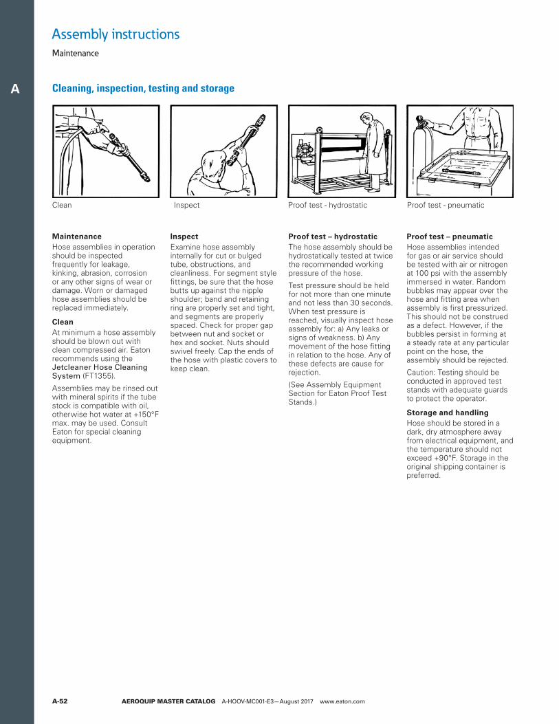
A
AEROQUIP MASTER CATALOG A-HOOV-MC001-E3—August 2017 www.eaton.comA-52
Cleaning, inspection, testing and storage
MaintenanceHose assemblies in operation should be inspected frequently for leakage, kinking, abrasion, corrosion or any other signs of wear or damage. Worn or damaged hose assemblies should be replaced immediately.
CleanAt minimum a hose assembly should be blown out with clean compressed air. Eaton recommends using the Jetcleaner Hose Cleaning System (FT1355).
Assemblies may be rinsed out with mineral spirits if the tube stock is compatible with oil, otherwise hot water at +150°F max. may be used. Consult Eaton for special cleaning equipment.
InspectExamine hose assembly internally for cut or bulged tube, obstructions, and cleanliness. For segment style fittings, be sure that the hose butts up against the nipple shoulder; band and retaining ring are properly set and tight, and segments are properly spaced. Check for proper gap between nut and socket or hex and socket. Nuts should swivel freely. Cap the ends of the hose with plastic covers to keep clean.
Proof test – hydrostaticThe hose assembly should be hydrostatically tested at twice the recommended working pressure of the hose.
Test pressure should be held for not more than one minute and not less than 30 seconds. When test pressure is reached, visually inspect hose assembly for: a) Any leaks or signs of weakness. b) Any movement of the hose fitting in relation to the hose. Any of these defects are cause for rejection.
(See Assembly Equipment Section for Eaton Proof Test Stands.)
Proof test – pneumaticHose assemblies intended for gas or air service should be tested with air or nitrogen at 100 psi with the assembly immersed in water. Random bubbles may appear over the hose and fitting area when assembly is first pressurized. This should not be construed as a defect. However, if the bubbles persist in forming at a steady rate at any particular point on the hose, the assembly should be rejected.
Caution: Testing should be conducted in approved test stands with adequate guards to protect the operator.
Storage and handlingHose should be stored in a dark, dry atmosphere away from electrical equipment, and the temperature should not exceed +90°F. Storage in the original shipping container is preferred.
Clean Inspect Proof test - hydrostatic Proof test - pneumatic
Assembly instructionsMaintenance
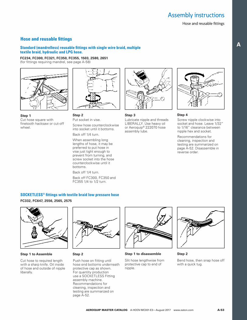
A
AEROQUIP MASTER CATALOG A-HOOV-MC001-E3—August 2017 www.eaton.com A-53
Hose and reusable fittings
Standard (mandrelless) reusable fittings with single wire braid, multiple textile braid, hydraulic and LPG hose.FC234, FC300, FC321, FC350, FC355, 1503, 2580, 2651 (for fittings requiring mandrel, see page A-58)
SOCKETLESS® fittings with textile braid low pressure hose FC332, FC647, 2556, 2565, 2575
Step 1Cut hose square with finetooth hacksaw or cut-off wheel.
Step 2Put socket in vise.
Screw hose counterclockwise into socket until it bottoms.
Back off 1/4 turn.
When assembling long lengths of hose, it may be preferred to put hose in vise just tight enough to prevent from turning, and screw socket into the hose counterclockwise until it bottoms.
Back off 1/4 turn.
Back off FC300, FC350 and FC355 1/4 to 1/2 turn.
Step 3Lubricate nipple and threads LIBERALLY. Use heavy oil or Aeroquip® 222070 hose assembly lube.
Step 4Screw nipple clockwise into socket and hose. Leave 1/32” to 1/16” clearance between nipple hex and socket.
Recommendations for cleaning, inspection and testing are summarized on page A-52. Disassemble in reverse order.
Step 1 to disassemble Step 2Step 1 to Assemble
Cut hose to required length with a sharp knife. Oil inside of hose and outside of nipple liberally.
Slit hose lengthwise from protective cap to end of nipple.
Bend hose, then snap hose off with a quick tug.
Step 2
Push hose on fitting until hose end bottoms underneath protective cap as shown. For quantity production use a SOCKETLESS Fitting assembly ma chine. Recom menda tions for cleaning, inspection and testing are summarized on page A-52.
Assembly instructionsHose and reusable fittings
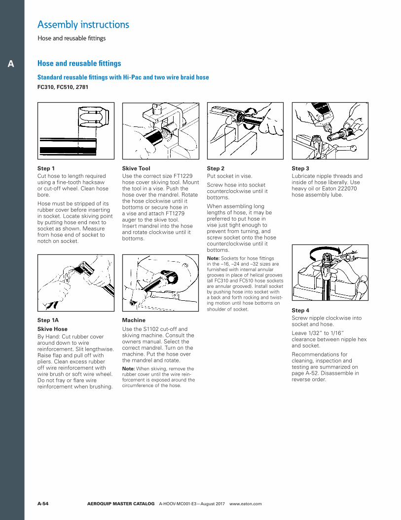
A
AEROQUIP MASTER CATALOG A-HOOV-MC001-E3—August 2017 www.eaton.comA-54
Standard reusable fittings with Hi-Pac and two wire braid hose FC310, FC510, 2781
Step 1Cut hose to length required using a fine-tooth hacksaw or cut-off wheel. Clean hose bore.
Hose must be stripped of its rub ber cover before inserting in socket. Locate skiving point by putting hose end next to socket as shown. Measure from hose end of socket to notch on socket.
Step 4Screw nipple clockwise into socket and hose.
Leave 1/32” to 1/16” clearance be tween nipple hex and socket.
Recommendations for cleaning, inspection and testing are summar ized on page A-52. Dis assemble in reverse order.
Skive ToolUse the correct size FT1229 hose cover skiving tool. Mount the tool in a vise. Push the hose over the mandrel. Rotate the hose clock wise until it bottoms or secure hose in a vise and attach FT1279 auger to the skive tool. Insert mandrel into the hose and rotate clockwise until it bottoms.
Step 2Put socket in vise.
Screw hose into socket counterclockwise until it bottoms.
When assembling long lengths of hose, it may be preferred to put hose in vise just tight enough to prevent from turning, and screw socket onto the hose counterclockwise until it bottoms.
ote:N Sockets for hose fittings in the –16, –24 and –32 sizes are furnished with internal annular grooves in place of helical grooves (all FC310 and FC510 hose sockets are annular grooved). Install socket by pushing hose into socket with a back and forth rocking and twist-ing motion until hose bottoms on shoulder of socket.
Machine
Use the S1102 cut-off and skiving machine. Consult the owners manual. Select the correct mandrel. Turn on the machine. Put the hose over the mandrel and rotate.
ote:N When skiving, remove the rubber cover until the wire rein-forcement is exposed around the circumference of the hose.
Step 1A
Skive HoseBy Hand: Cut rubber cover around down to wire reinforcement. Slit lengthwise. Raise flap and pull off with pliers. Clean excess rubber off wire reinforcement with wire brush or soft wire wheel. Do not fray or flare wire reinforcement when brushing.
Step 3Lubricate nipple threads and inside of hose liberally. Use heavy oil or Eaton 222070 hose assembly lube.
Hose and reusable fittings
Assembly instructionsHose and reusable fittings
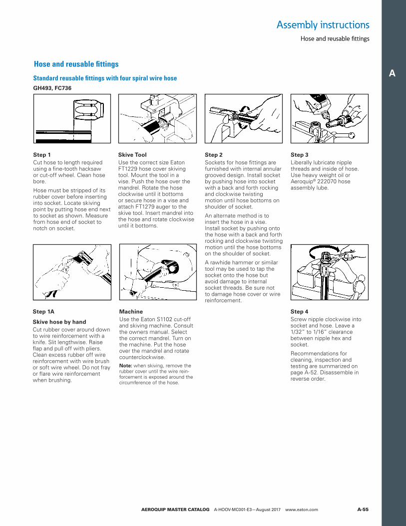
A
AEROQUIP MASTER CATALOG A-HOOV-MC001-E3—August 2017 www.eaton.com A-55
Assembly instructionsHose and reusable fittings
Standard reusable fittings with four spiral wire hose GH493, FC736
Step 1Cut hose to length required using a fine-tooth hacksaw or cut-off wheel. Clean hose bore.
Hose must be stripped of its rubber cover before inserting into socket. Locate skiving point by putting hose end next to socket as shown. Measure from hose end of socket to notch on socket.
Skive ToolUse the correct size Eaton FT1229 hose cover skiving tool. Mount the tool in a vise. Push the hose over the mandrel. Rotate the hose clockwise until it bottoms or secure hose in a vise and attach FT1279 auger to the skive tool. Insert mandrel into the hose and rotate clockwise until it bottoms.
Step 2Sockets for hose fittings are furnished with internal annular grooved design. Install socket by pushing hose into socket with a back and forth rocking and clockwise twisting motion until hose bottoms on shoulder of socket.
An alternate method is to insert the hose in a vise. Install socket by pushing onto the hose with a back and forth rocking and clockwise twisting motion until the hose bottoms on the shoulder of socket.
A rawhide hammer or similar tool may be used to tap the socket onto the hose but avoid damage to internal socket threads. Be sure not to damage hose cover or wire reinforcement.
Step 4Screw nipple clockwise into socket and hose. Leave a 1/32” to 1/16” clearance between nipple hex and socket.
Recommendations for cleaning, inspection and testing are summarized on page A-52. Dis assemble in reverse order.
Step 1A
Skive hose by handCut rubber cover around down to wire reinforcement with a knife. Slit lengthwise. Raise flap and pull off with pliers. Clean excess rubber off wire reinforcement with wire brush or soft wire wheel. Do not fray or flare wire reinforcement when brushing.
MachineUse the Eaton S1102 cut-off and skiving machine. Consult the owners manual. Select the correct mandrel. Turn on the machine. Put the hose over the mandrel and rotate counterclockwise.
ote:N when skiving, remove the rubber cover until the wire rein-forcement is exposed around the circumference of the hose.
Step 3Liberally lubricate nipple threads and inside of hose. Use heavy weight oil or Aeroquip® 222070 hose assembly lube.
Hose and reusable fittings
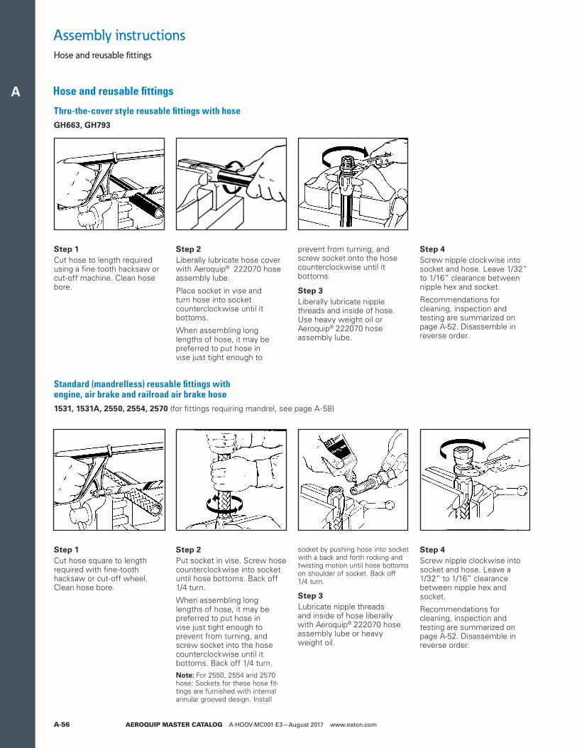
A
AEROQUIP MASTER CATALOG A-HOOV-MC001-E3—August 2017 www.eaton.comA-56
Thru-the-cover style reusable fittings with hose GH663, GH793
Standard (mandrelless) reusable fittings with engine, air brake and railroad air brake hose 1531, 1531A, 2550, 2554, 2570 (for fittings requiring mandrel, see page A-58)
Step 1Cut hose to length required using a fine tooth hacksaw or cut-off machine. Clean hose bore.
Step 2Liberally lubricate hose cover with Aeroquip® 222070 hose assembly lube.
Place socket in vise and turn hose into socket counterclockwise until it bottoms.
When assembling long lengths of hose, it may be preferred to put hose in vise just tight enough to
prevent from turning, and screw socket onto the hose counterclockwise until it bottoms.
Step 3Liberally lubricate nipple threads and inside of hose. Use heavy weight oil or Aeroquip® 222070 hose assembly lube.
Step 4Screw nipple clockwise into socket and hose. Leave 1/32” to 1/16” clearance between nipple hex and socket.
Recommendations for cleaning, inspection and testing are summarized on page A-52. Dis assemble in reverse order.
Step 1Cut hose square to length required with fine-tooth hacksaw or cut-off wheel. Clean hose bore.
Step 2Put socket in vise. Screw hose counterclockwise into socket until hose bottoms. Back off 1/4 turn.
When assembling long lengths of hose, it may be preferred to put hose in vise just tight enough to prevent from turning, and screw socket into the hose counterclockwise until it bottoms. Back off 1/4 turn.
ote:N For 2550, 2554 and 2570 hose: Sockets for these hose fit-tings are furnished with internal annular grooved design. Install
socket by pushing hose into socket with a back and forth rocking and twisting motion until hose bottoms on shoulder of socket. Back off 1/4 turn.
Step 3Lubricate nipple threads and inside of hose liberally with Aeroquip® 222070 hose assembly lube or heavy weight oil.
Step 4Screw nipple clockwise into socket and hose. Leave a 1/32” to 1/16” clearance between nipple hex and socket.
Recommendations for cleaning, inspection and testing are summarized on page A-52. Dis assemble in reverse order.
Assembly instructionsHose and reusable fittings
Hose and reusable fittings
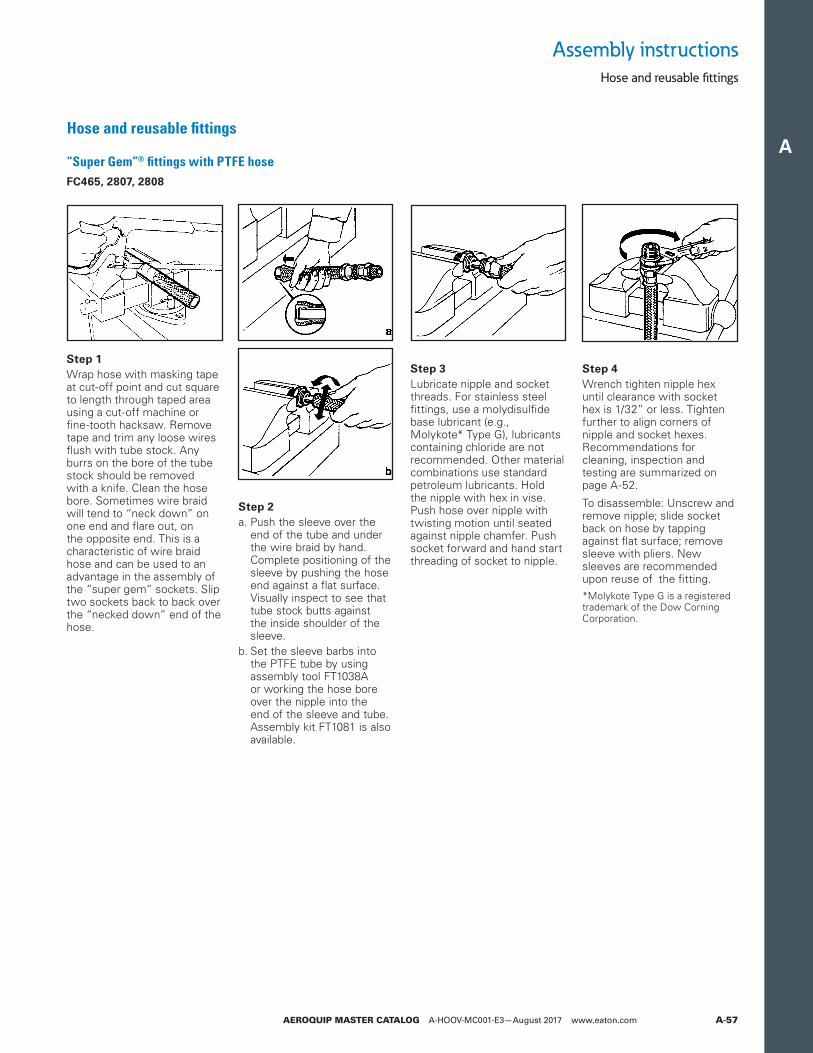
A
AEROQUIP MASTER CATALOG A-HOOV-MC001-E3—August 2017 www.eaton.com A-57
“Super Gem”® fittings with PTFE hose FC465, 2807, 2808
Step 3Lubricate nipple and socket threads. For stainless steel fittings, use a molydisulfide base lubricant (e.g., Molykote* Type G), lubricants containing chloride are not recommended. Other material combinations use standard petroleum lubricants. Hold the nipple with hex in vise. Push hose over nipple with twisting motion until seated against nipple chamfer. Push socket forward and hand start threading of socket to nipple.
Step 4Wrench tighten nipple hex until clearance with socket hex is 1/32” or less. Tighten further to align corners of nipple and socket hexes. Recommenda tions for cleaning, inspection and testing are summarized on page A-52.
To disassemble: Unscrew and remove nipple; slide socket back on hose by tapping against flat surface; remove sleeve with pliers. New sleeves are recommended upon reuse of the fitting.*Molykote Type G is a registered trademark of the Dow Corning Corporation.
Step 1Wrap hose with masking tape at cut-off point and cut square to length through taped area using a cut-off machine or fine-tooth hacksaw. Remove tape and trim any loose wires flush with tube stock. Any burrs on the bore of the tube stock should be removed with a knife. Clean the hose bore. Some times wire braid will tend to “neck down” on one end and flare out, on the opposite end. This is a characteristic of wire braid hose and can be used to an advantage in the assembly of the “super gem” sockets. Slip two sockets back to back over the “necked down” end of the hose.
Step 2a. Push the sleeve over the
end of the tube and under the wire braid by hand. Complete positioning of the sleeve by pushing the hose end against a flat surface. Visually inspect to see that tube stock butts against the inside shoulder of the sleeve.
b. Set the sleeve barbs into the PTFE tube by using assembly tool FT1038A or working the hose bore over the nipple into the end of the sleeve and tube. Assembly kit FT1081 is also available.
Assembly instructionsHose and reusable fittings
Hose and reusable fittings
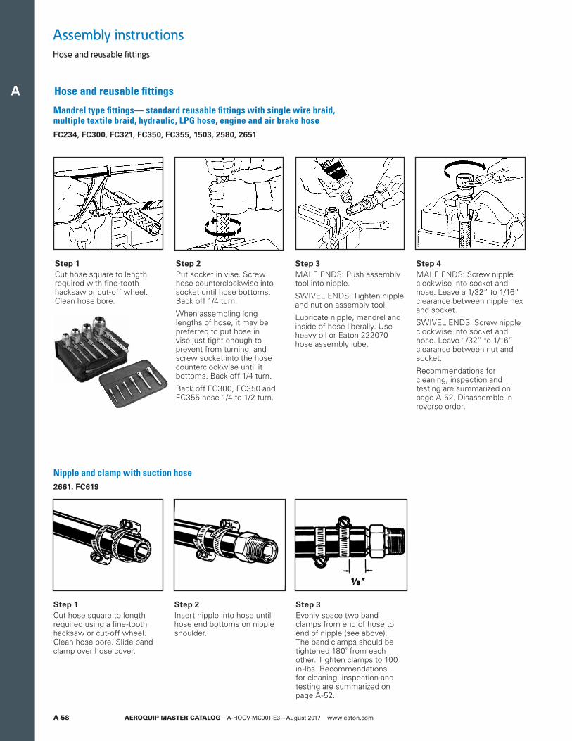
A
AEROQUIP MASTER CATALOG A-HOOV-MC001-E3—August 2017 www.eaton.comA-58
Mandrel type fittings— standard reusable fittings with single wire braid, multiple textile braid, hydraulic, LPG hose, engine and air brake hose FC234, FC300, FC321, FC350, FC355, 1503, 2580, 2651
Nipple and clamp with suction hose2661, FC619
Step 1Cut hose square to length required with fine-tooth hacksaw or cut-off wheel. Clean hose bore.
Step 2Put socket in vise. Screw hose counterclockwise into socket until hose bottoms. Back off 1/4 turn.
When assembling long lengths of hose, it may be preferred to put hose in vise just tight enough to prevent from turning, and screw socket into the hose counterclockwise until it bottoms. Back off 1/4 turn.
Back off FC300, FC350 and FC355 hose 1/4 to 1/2 turn.
Step 3MALE ENDS: Push assembly tool into nipple.
SWIVEL ENDS: Tighten nipple and nut on assembly tool.
Lubricate nipple, mandrel and inside of hose liberally. Use heavy oil or Eaton 222070 hose assembly lube.
Step 4MALE ENDS: Screw nipple clockwise into socket and hose. Leave a 1/32” to 1/16” clearance between nipple hex and socket.
SWIVEL ENDS: Screw nipple clockwise into socket and hose. Leave 1/32” to 1/16” clearance between nut and socket.
Recommendations for cleaning, inspection and testing are summarized on page A-52. Disassemble in reverse order.
Step 1Cut hose square to length required using a fine-tooth hacksaw or cut-off wheel. Clean hose bore. Slide band clamp over hose cover.
Step 2Insert nipple into hose until hose end bottoms on nipple shoulder.
Step 3Evenly space two band clamps from end of hose to end of nipple (see above). The band clamps should be tightened 180˚ from each other. Tighten clamps to 100 in-lbs. Recommendations for cleaning, inspection and testing are summarized on page A-52.
Assembly instructionsHose and reusable fittings
Hose and reusable fittings
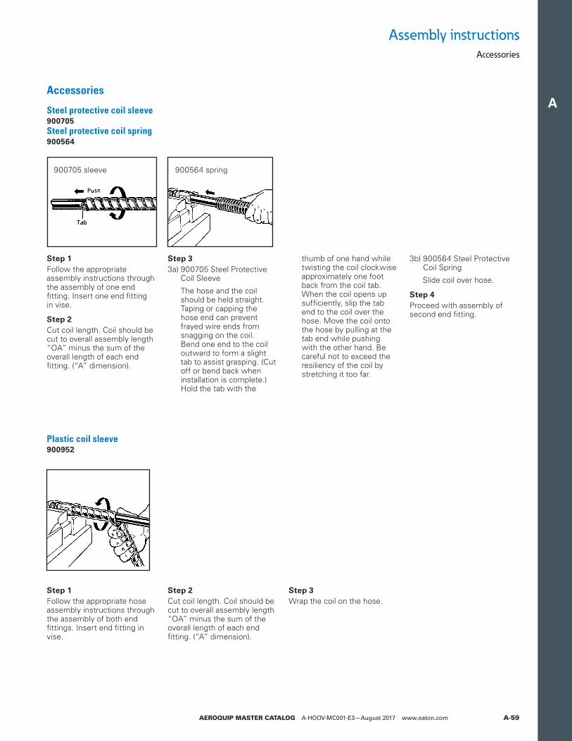
A
AEROQUIP MASTER CATALOG A-HOOV-MC001-E3—August 2017 www.eaton.com A-59
Steel protective coil sleeve 900705 Steel protective coil spring 900564
Plastic coil sleeve 900952
Step 1Follow the appropriate assembly instructions through the assembly of one end fitting. Insert one end fitting in vise.
Step 2Cut coil length. Coil should be cut to overall assembly length “OA” minus the sum of the overall length of each end fitting. (“A” dimension).
Step 33a) 900705 Steel Protective
Coil Sleeve
3a) The hose and the coil should be held straight. Taping or capping the hose end can prevent frayed wire ends from snagging on the coil. Bend one end to the coil outward to form a slight tab to assist grasping. (Cut off or bend back when installation is complete.) Hold the tab with the
thumb of one hand while twisting the coil clockwise approximately one foot back from the coil tab. When the coil opens up sufficiently, slip the tab end to the coil over the hose. Move the coil onto the hose by pulling at the tab end while pushing with the other hand. Be careful not to exceed the resiliency of the coil by stretching it too far.
3b) 900564 Steel Protective Coil Spring
3a) Slide coil over hose.
Step 4Proceed with assembly of second end fitting.
Step 1Follow the appropriate hose assembly instructions through the assembly of both end fittings. Insert end fitting in vise.
Step 2Cut coil length. Coil should be cut to overall assembly length “OA” minus the sum of the overall length of each end fitting. (“A” dimension).
Step 3Wrap the coil on the hose.
900705 sleeve 900564 spring
Assembly instructionsAccessories
Accessories
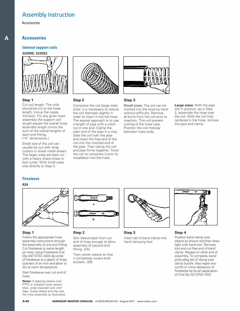
A
AEROQUIP MASTER CATALOG A-HOOV-MC001-E3—August 2017 www.eaton.comA-60
Internal support coils 222005, 222022
Firesleeve 624
Step 1Cut coil length. The coils should be cut to the hose length, minus the nipple intrusion. For any given hose assembly the support coil length equals the overall hose assembly length minus the sum of the overall lengths of each end fitting. (“A” dimensions.)
Small size of the coil can usually be cut with strap cutters or sheet metal shears. The larger sizes are best cut with a heavy sharp chisel or bolt cutter. With small sizes skip directly to Step 3.
Step 2Compress the coil (large sizes only). It is necessary to reduce the coil diameter slightly in order to insert it into the hose. The easiest approach is to use a length of pipe with a notch cut in one end. Clamp the plain end of the pipe in a vise, slide the coil over the pipe and insert the free end of the coil into the notched end of the pipe. Then clamp the coil and pipe firmly together. Twist the coil to compress it prior to installation into the hose.
Step 3Small sizes: The coil can be worked into the hose by hand without difficulty. Remove all burrs from the coil prior to insertion. This will prevent cutting of the hose tube. Position the coil midway between hose ends.
Large sizes: With the pipe still in position, as in Step 2, assemble the hose over the coil. With the coil fully centered in the hose, remove the pipe and clamp.
Step 1Follow the appropriate hose assembly instructions through the assembly of one end fitting. Cut firesleeve to same length as hose; using Firesleeve End Dip (AE13702–003) dip ends of firesleeve to a depth of three quarters of an inch and allow to dry at room temperature.
Start firesleeve over cut end of hose.
otes:N If applying sleeve over PTFE or stripped cover assem-blies, wrap ex posed wire with tape. Grasp sleeve and slip over the hose assembly as illustrated.
Step 2Skin sleeve back from cut end of hose enough to allow assembly of second end fitting. (2A)
Then center sleeve so that it completely covers both sockets. (2B)
Step 3Insert tail of band clamp into hand clamping tool.
Step 4Position band clamp over sleeve as shown and then draw tight with hand tool. Remove tool and cut free end of band clamp. Repeat on other end of assembly. To complete, bend protruding tail of clamp over clamp buckle. Also repair any scuffs or minor abrasions of firesleeve by brush application of End Dip AE13702–003.
Assembly instructionAccessories
Accessories