Embed Size (px)
Citation preview
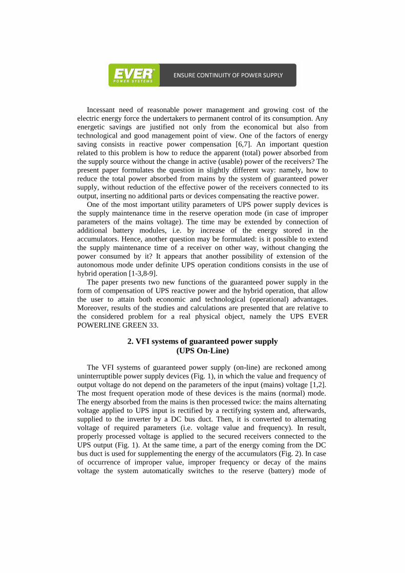
Compensation of reactive power and hybrid operation
in the systems of uninterruptible power supply (UPS)
Karol Bednarek
EVER Sp. z o.o.
62-020 Swarzędz, ul. Grudzińskiego 30, e-mail: [email protected]
The paper presents analysis of possible compensation of reactive power by internal
input blocks of Uninterruptible Power Systems (UPS), without the use of additional power
electronic converters or stationary passive elements (on the example of UPS EVER
POWERLINE GREEN 33). Moreover, the consideration related to additional UPS
functionality consisting in hybrid operation, enabling longer duration of supply
maintenance within a definite region of the mains voltage variations. The results of
measurements and calculations are presented, that have been carried out in a given
physical system. Final part of the paper includes a summary of the obtained results.
KEYWORDS: the systems of uninterruptible power supply, reactive power
compensation, hybrid operation
1. Introduction
Taking into account common use of electric and electronic parts, devices, and
systems in all the areas of human activity, both in private and professional realm
(science, industry, administration, services, etc.), the problems related to the quality
of delivered power and to reasonable power management become very important.
The faults or interruptions in electric power delivery are not only burdensome to
the users, due to precluded operation of the electric equipment, but may be
conducive to severe consequences. These consequences may be of economic,
technological, and information nature, in the form of data loss in computer
systems, damage to electric equipment, expensive shutdowns of the equipment
operation, or the discomfort related to insufficient heating of usable premises
(mainly in winter) or operation of the access control devices (automatic gates, the
parts of intelligent buildings, alarm systems etc.).
A good solution to such problems is the use of a guaranteed power supply
provided by UPS emergency power supply devices. In the reserve operation mode
(actuated in case of improper parameters or decay of the mains voltage) these
devices use the electric energy stored in the accumulators (batteries), in order to
ensure feeding of the secured receivers (of key meaning) within a predefined time,
with a view to terminate the current processes [1-5]. These systems often offer
many additional functions that enable more optimized power management,
financial savings, or improved quality and security of operation of the equipment.
Incessant need of reasonable power management and growing cost of the
electric energy force the undertakers to permanent control of its consumption. Any
energetic savings are justified not only from the economical but also from
technological and good management point of view. One of the factors of energy
saving consists in reactive power compensation [6,7]. An important question
related to this problem is how to reduce the apparent (total) power absorbed from
the supply source without the change in active (usable) power of the receivers? The
present paper formulates the question in slightly different way: namely, how to
reduce the total power absorbed from mains by the system of guaranteed power
supply, without reduction of the effective power of the receivers connected to its
output, inserting no additional parts or devices compensating the reactive power.
One of the most important utility parameters of UPS power supply devices is
the supply maintenance time in the reserve operation mode (in case of improper
parameters of the mains voltage). The time may be extended by connection of
additional battery modules, i.e. by increase of the energy stored in the
accumulators. Hence, another question may be formulated: is it possible to extend
the supply maintenance time of a receiver on other way, without changing the
power consumed by it? It appears that another possibility of extension of the
autonomous mode under definite UPS operation conditions consists in the use of
hybrid operation [1-3,8-9].
The paper presents two new functions of the guaranteed power supply in the
form of compensation of UPS reactive power and the hybrid operation, that allow
the user to attain both economic and technological (operational) advantages.
Moreover, results of the studies and calculations are presented that are relative to
the considered problem for a real physical object, namely the UPS EVER
POWERLINE GREEN 33.
2. VFI systems of guaranteed power supply
(UPS On-Line)
The VFI systems of guaranteed power supply (on-line) are reckoned among
uninterruptible power supply devices (Fig. 1), in which the value and frequency of
output voltage do not depend on the parameters of the input (mains) voltage [1,2].
The most frequent operation mode of these devices is the mains (normal) mode.
The energy absorbed from the mains is then processed twice: the mains alternating
voltage applied to UPS input is rectified by a rectifying system and, afterwards,
supplied to the inverter by a DC bus duct. Then, it is converted to alternating
voltage of required parameters (i.e. voltage value and frequency). In result,
properly processed voltage is applied to the secured receivers connected to the
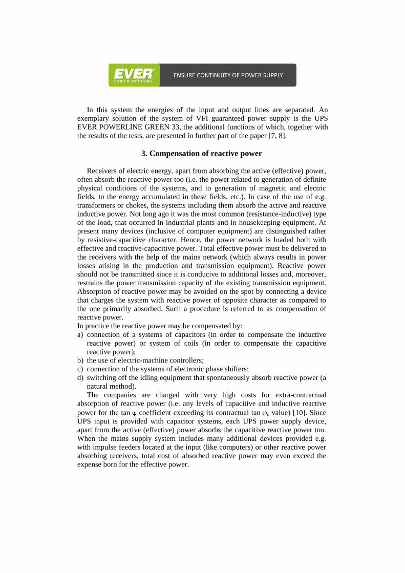
UPS output (Fig. 1). At the same time, a part of the energy coming from the DC
bus duct is used for supplementing the energy of the accumulators (Fig. 2). In case
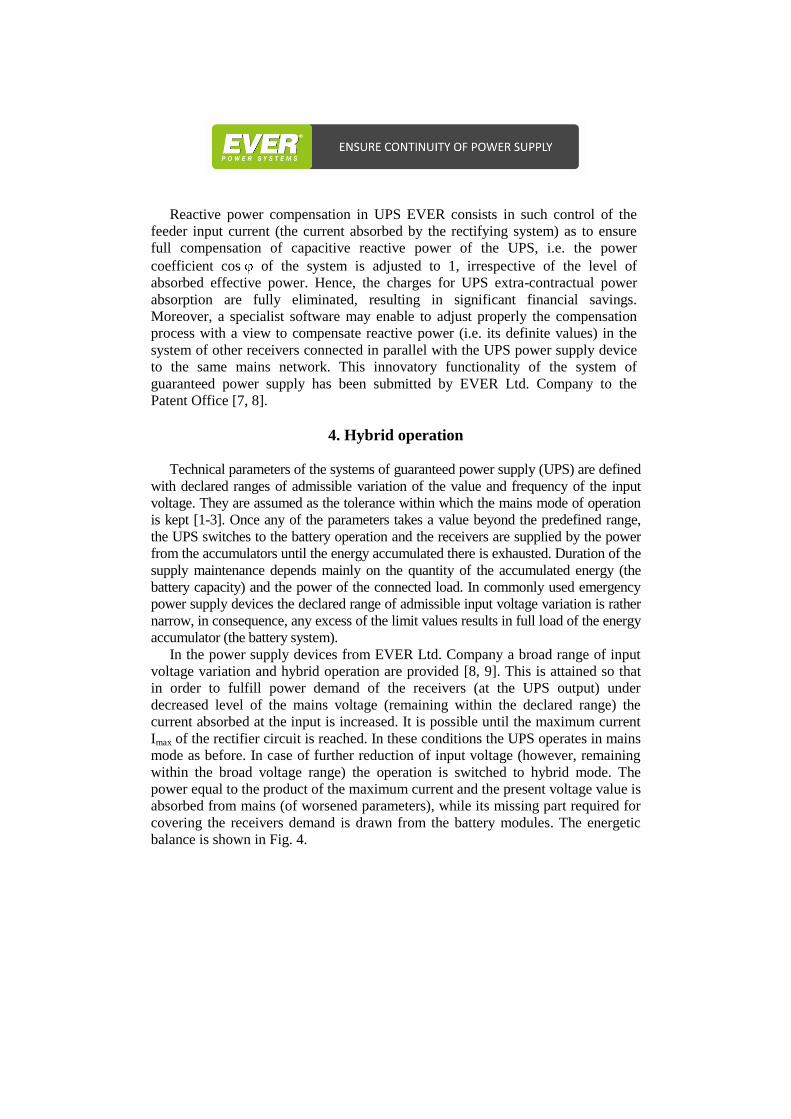
of occurrence of improper value, improper frequency or decay of the mains
voltage the system automatically switches to the reserve (battery) mode of
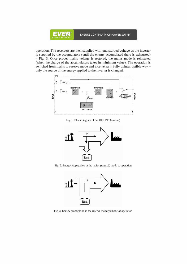
operation. The receivers are then supplied with undisturbed voltage as the inverter
is supplied by the accumulators (until the energy accumulated there is exhausted)
– Fig. 3. Once proper mains voltage is restored, the mains mode is reinstated
(when the charge of the accumulators takes its minimum value). The operation is
switched from mains to reserve mode and vice versa in fully uninterruptible way –
only the source of the energy applied to the inverter is changed.
Fig. 1. Block diagram of the UPS VFI (on-line)
Fig. 2. Energy propagation in the mains (normal) mode of operation
Fig. 3. Energy propagation in the reserve (battery) mode of operation
In this system the energies of the input and output lines are separated. An
exemplary solution of the system of VFI guaranteed power supply is the UPS
EVER POWERLINE GREEN 33, the additional functions of which, together with
the results of the tests, are presented in further part of the paper [7, 8].
3. Compensation of reactive power
Receivers of electric energy, apart from absorbing the active (effective) power,
often absorb the reactive power too (i.e. the power related to generation of definite
physical conditions of the systems, and to generation of magnetic and electric
fields, to the energy accumulated in these fields, etc.). In case of the use of e.g.
transformers or chokes, the systems including them absorb the active and reactive
inductive power. Not long ago it was the most common (resistance-inductive) type
of the load, that occurred in industrial plants and in housekeeping equipment. At
present many devices (inclusive of computer equipment) are distinguished rather
by resistive-capacitive character. Hence, the power network is loaded both with
effective and reactive-capacitive power. Total effective power must be delivered to
the receivers with the help of the mains network (which always results in power
losses arising in the production and transmission equipment). Reactive power
should not be transmitted since it is conducive to additional losses and, moreover,
restrains the power transmission capacity of the existing transmission equipment.
Absorption of reactive power may be avoided on the spot by connecting a device
that charges the system with reactive power of opposite character as compared to
the one primarily absorbed. Such a procedure is referred to as compensation of
reactive power.
In practice the reactive power may be compensated by:
a) connection of a systems of capacitors (in order to compensate the inductive
reactive power) or system of coils (in order to compensate the capacitive
reactive power);
b) the use of electric-machine controllers;
c) connection of the systems of electronic phase shifters;
d) switching off the idling equipment that spontaneously absorb reactive power (a
natural method).
The companies are charged with very high costs for extra-contractual
absorption of reactive power (i.e. any levels of capacitive and inductive reactive
power for the tan coefficient exceeding its contractual tan o value) [10]. Since
UPS input is provided with capacitor systems, each UPS power supply device,
apart from the active (effective) power absorbs the capacitive reactive power too.
When the mains supply system includes many additional devices provided e.g.
with impulse feeders located at the input (like computers) or other reactive power
absorbing receivers, total cost of absorbed reactive power may even exceed the
expense born for the effective power.
Reactive power compensation in UPS EVER consists in such control of the
feeder input current (the current absorbed by the rectifying system) as to ensure
full compensation of capacitive reactive power of the UPS, i.e. the power
coefficient cos of the system is adjusted to 1, irrespective of the level of
absorbed effective power. Hence, the charges for UPS extra-contractual power
absorption are fully eliminated, resulting in significant financial savings.
Moreover, a specialist software may enable to adjust properly the compensation
process with a view to compensate reactive power (i.e. its definite values) in the
system of other receivers connected in parallel with the UPS power supply device
to the same mains network. This innovatory functionality of the system of
guaranteed power supply has been submitted by EVER Ltd. Company to the
Patent Office [7, 8].
4. Hybrid operation
Technical parameters of the systems of guaranteed power supply (UPS) are defined
with declared ranges of admissible variation of the value and frequency of the input
voltage. They are assumed as the tolerance within which the mains mode of operation
is kept [1-3]. Once any of the parameters takes a value beyond the predefined range,
the UPS switches to the battery operation and the receivers are supplied by the power
from the accumulators until the energy accumulated there is exhausted. Duration of the
supply maintenance depends mainly on the quantity of the accumulated energy (the
battery capacity) and the power of the connected load. In commonly used emergency
power supply devices the declared range of admissible input voltage variation is rather
narrow, in consequence, any excess of the limit values results in full load of the energy
accumulator (the battery system).
In the power supply devices from EVER Ltd. Company a broad range of input
voltage variation and hybrid operation are provided [8, 9]. This is attained so that
in order to fulfill power demand of the receivers (at the UPS output) under
decreased level of the mains voltage (remaining within the declared range) the
current absorbed at the input is increased. It is possible until the maximum current
Imax of the rectifier circuit is reached. In these conditions the UPS operates in mains
mode as before. In case of further reduction of input voltage (however, remaining
within the broad voltage range) the operation is switched to hybrid mode. The
power equal to the product of the maximum current and the present voltage value is
absorbed from mains (of worsened parameters), while its missing part required for
covering the receivers demand is drawn from the battery modules. The energetic
balance is shown in Fig. 4.
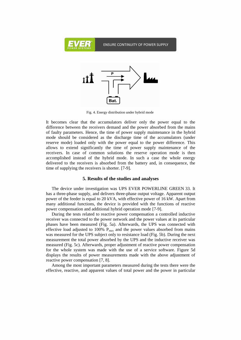
Fig. 4. Energy distribution under hybrid mode
It becomes clear that the accumulators deliver only the power equal to the
difference between the receivers demand and the power absorbed from the mains
of faulty parameters. Hence, the time of power supply maintenance in the hybrid
mode should be considered as the discharge time of the accumulators (under
reserve mode) loaded only with the power equal to the power difference. This
allows to extend significantly the time of power supply maintenance of the
receivers. In case of common solutions the reserve operation mode is then
accomplished instead of the hybrid mode. In such a case the whole energy
delivered to the receivers is absorbed from the battery and, in consequence, the
time of supplying the receivers is shorter. [7-9].
5. Results of the studies and analyses
The device under investigation was UPS EVER POWERLINE GREEN 33. It
has a three-phase supply, and delivers three-phase output voltage. Apparent output
power of the feeder is equal to 20 kVA, with effective power of 16 kW. Apart from
many additional functions, the device is provided with the functions of reactive
power compensation and additional hybrid operation mode [7-9].
During the tests related to reactive power compensation a controlled inductive
receiver was connected to the power network and the power values at its particular
phases have been measured (Fig. 5a). Afterwards, the UPS was connected with
effective load adjusted to 100% Pmax and the power values absorbed from mains
was measured for the UPS subject only to resistance load (Fig. 5b). During the next
measurement the total power absorbed by the UPS and the inductive receiver was
measured (Fig. 5c). Afterwards, proper adjustment of reactive power compensation
for the whole system was made with the use of a service software. Figure 5d
displays the results of power measurements made with the above adjustment of
reactive power compensation [7, 8].
Among the most important parameters measured during the tests there were the
effective, reactive, and apparent values of total power and the power in particular
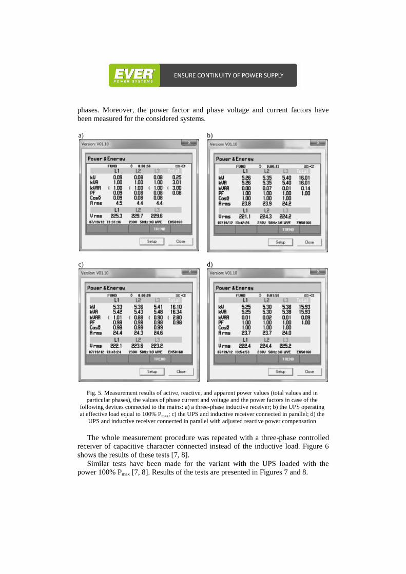
phases. Moreover, the power factor and phase voltage and current factors have
been measured for the considered systems.
a) b)
c)
d)
Fig. 5. Measurement results of active, reactive, and apparent power values (total values and in
particular phases), the values of phase current and voltage and the power factors in case of the
following devices connected to the mains: a) a three-phase inductive receiver; b) the UPS operating
at effective load equal to 100% Pmax; c) the UPS and inductive receiver connected in parallel; d) the
UPS and inductive receiver connected in parallel with adjusted reactive power compensation
The whole measurement procedure was repeated with a three-phase controlled
receiver of capacitive character connected instead of the inductive load. Figure 6
shows the results of these tests [7, 8].
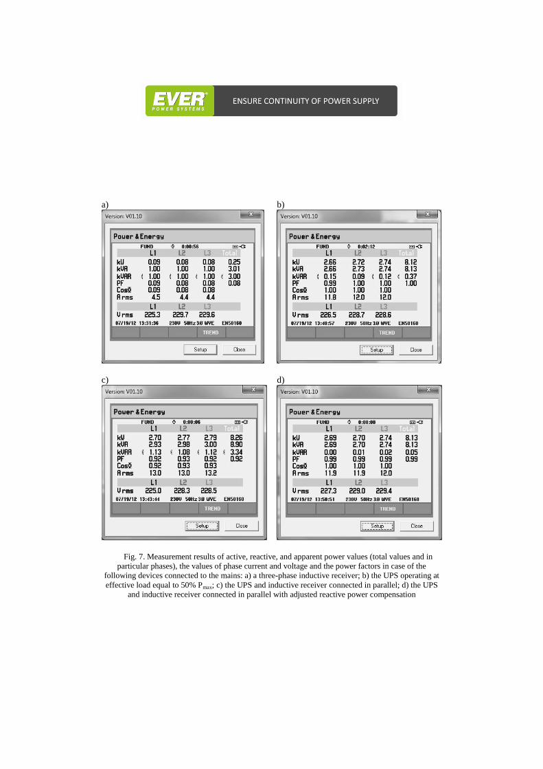
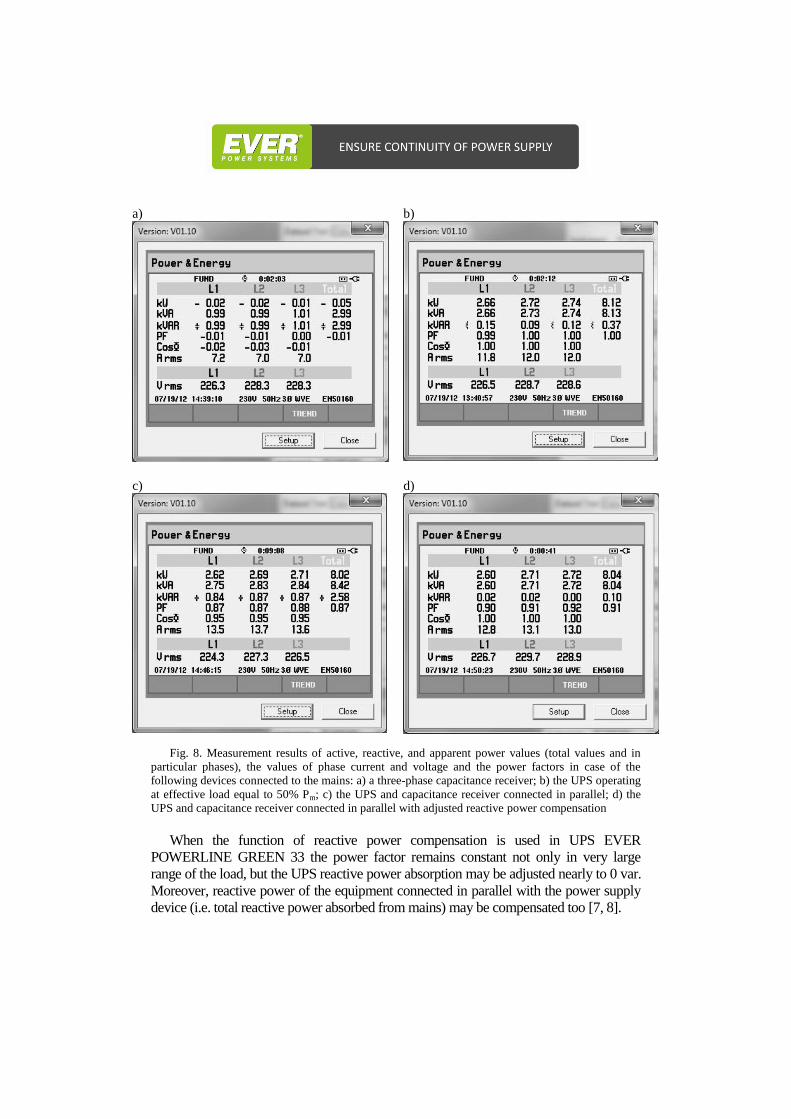
Similar tests have been made for the variant with the UPS loaded with the
power 100% Pmax [7, 8]. Results of the tests are presented in Figures 7 and 8.
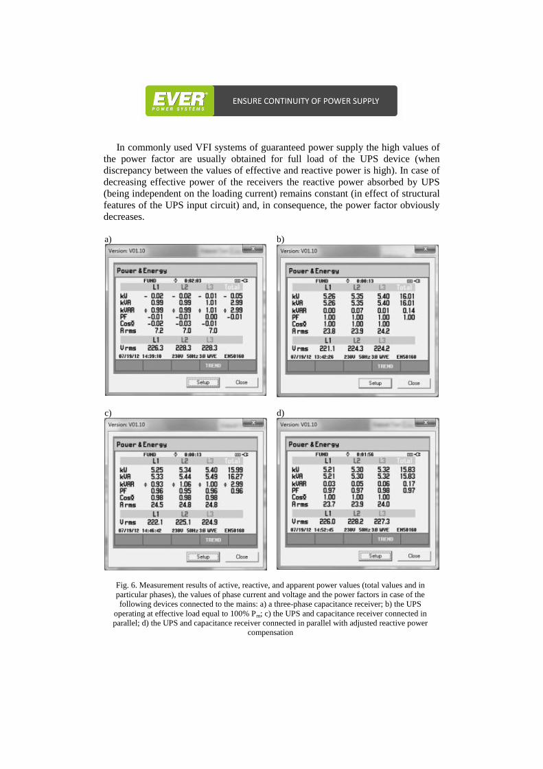
In commonly used VFI systems of guaranteed power supply the high values of
the power factor are usually obtained for full load of the UPS device (when
discrepancy between the values of effective and reactive power is high). In case of
decreasing effective power of the receivers the reactive power absorbed by UPS
(being independent on the loading current) remains constant (in effect of structural
features of the UPS input circuit) and, in consequence, the power factor obviously
decreases.
a) b)
c)
d)
Fig. 6. Measurement results of active, reactive, and apparent power values (total values and in
particular phases), the values of phase current and voltage and the power factors in case of the
following devices connected to the mains: a) a three-phase capacitance receiver; b) the UPS
operating at effective load equal to 100% Pm; c) the UPS and capacitance receiver connected in
parallel; d) the UPS and capacitance receiver connected in parallel with adjusted reactive power
compensation
a) b)
c)
d)
Fig. 7. Measurement results of active, reactive, and apparent power values (total values and in
particular phases), the values of phase current and voltage and the power factors in case of the
following devices connected to the mains: a) a three-phase inductive receiver; b) the UPS operating at
effective load equal to 50% Pmax; c) the UPS and inductive receiver connected in parallel; d) the UPS
and inductive receiver connected in parallel with adjusted reactive power compensation
a) b)
c)
d)
Fig. 8. Measurement results of active, reactive, and apparent power values (total values and in
particular phases), the values of phase current and voltage and the power factors in case of the
following devices connected to the mains: a) a three-phase capacitance receiver; b) the UPS operating
at effective load equal to 50% Pm; c) the UPS and capacitance receiver connected in parallel; d) the
UPS and capacitance receiver connected in parallel with adjusted reactive power compensation
When the function of reactive power compensation is used in UPS EVER
POWERLINE GREEN 33 the power factor remains constant not only in very large
range of the load, but the UPS reactive power absorption may be adjusted nearly to 0 var.
Moreover, reactive power of the equipment connected in parallel with the power supply
device (i.e. total reactive power absorbed from mains) may be compensated too [7, 8].
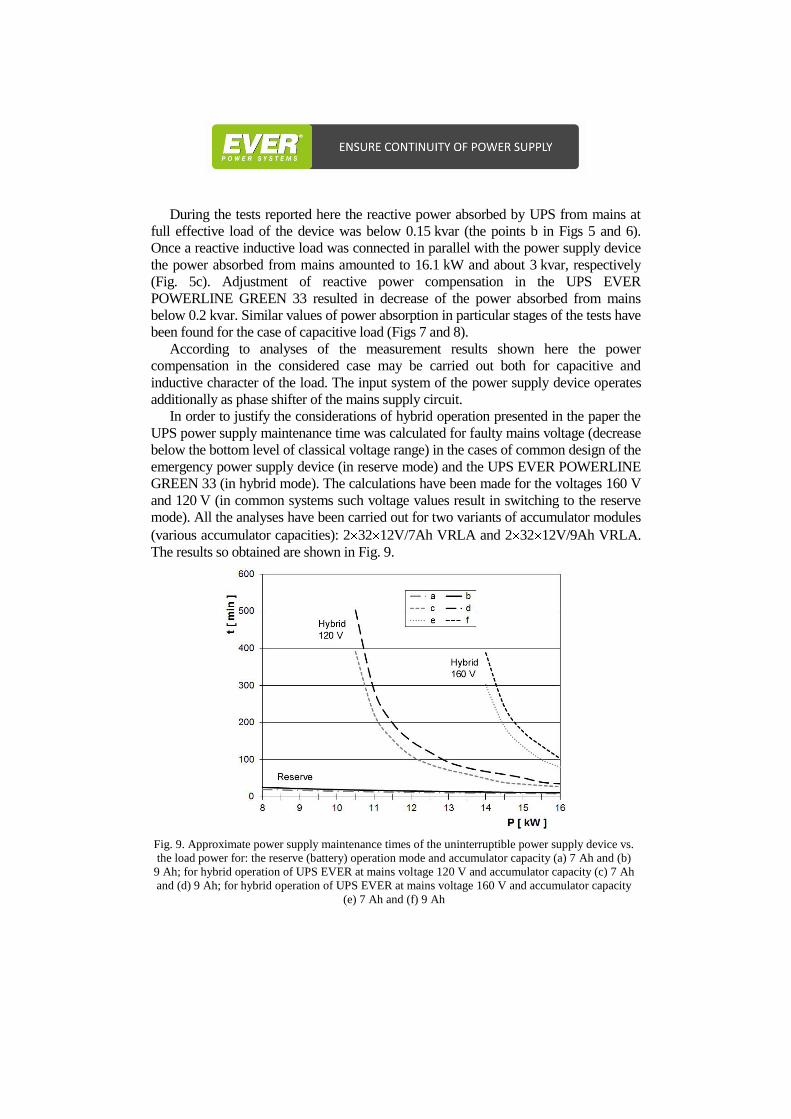
During the tests reported here the reactive power absorbed by UPS from mains at
full effective load of the device was below 0.15 kvar (the points b in Figs 5 and 6).
Once a reactive inductive load was connected in parallel with the power supply device
the power absorbed from mains amounted to 16.1 kW and about 3 kvar, respectively
(Fig. 5c). Adjustment of reactive power compensation in the UPS EVER
POWERLINE GREEN 33 resulted in decrease of the power absorbed from mains
below 0.2 kvar. Similar values of power absorption in particular stages of the tests have
been found for the case of capacitive load (Figs 7 and 8).
According to analyses of the measurement results shown here the power
compensation in the considered case may be carried out both for capacitive and
inductive character of the load. The input system of the power supply device operates
additionally as phase shifter of the mains supply circuit.
In order to justify the considerations of hybrid operation presented in the paper the
UPS power supply maintenance time was calculated for faulty mains voltage (decrease
below the bottom level of classical voltage range) in the cases of common design of the
emergency power supply device (in reserve mode) and the UPS EVER POWERLINE
GREEN 33 (in hybrid mode). The calculations have been made for the voltages 160 V
and 120 V (in common systems such voltage values result in switching to the reserve
mode). All the analyses have been carried out for two variants of accumulator modules
(various accumulator capacities): 2 32 12V/7Ah VRLA and 2 32 12V/9Ah VRLA.
The results so obtained are shown in Fig. 9.
Fig. 9. Approximate power supply maintenance times of the uninterruptible power supply device vs.
the load power for: the reserve (battery) operation mode and accumulator capacity (a) 7 Ah and (b)
9 Ah; for hybrid operation of UPS EVER at mains voltage 120 V and accumulator capacity (c) 7 Ah
and (d) 9 Ah; for hybrid operation of UPS EVER at mains voltage 160 V and accumulator capacity
(e) 7 Ah and (f) 9 Ah

The calculated power supply maintenance times are of approximate character, since
they depend not only on the quantity of accumulated energy and the power of the
connected load, but, to significant degree, on the charging degree, internal resistance,
and type of the accumulators, as well as on the operational and environmental
conditions [9].
In hybrid mode the duration of power supply maintenance is many times longer as
compared to duration of autonomous operation in reserve mode (undergoing in the
same conditions in common guaranteed supply systems), since the accumulator battery
is loaded only with the difference of the powers (i.e. the difference between the
receivers demand and the power delivered by the mains of faulty parameters) [3, 9].
6. Summarizing notes and conclusions
The systems of guaranteed power supply are, in many situations, important
parts of the supply system, that enable proper operation of the secured receivers.
A very advantageous function of UPS consists in reactive power compensation.
This enables evident economic benefits and energy savings at many levels of the
supply system.
The tests and analyses reported here gave clear evidence that introduction of the
hybrid operation mode (a broad range of input voltage changes) allows to extend
duration of autonomous UPS and VFI operation for a definite range of the mains
voltage variation. At the same time, the life of the accumulators used for this
purpose is extended too (in result of partial relief of the battery during the hybrid
operation mode, as a certain part of the energy is absorbed from the mains of faulty
parameters). At lower value of the load power the total energy delivered to the
receivers under the whole declared voltage range, is absorbed from mains (without
the use of the battery). Relinquishment of a UPS power supply device in the supply
systems of highly sensitive receivers may be conducive to significant
consequences, namely the loss of processed information, damage or disturbance of
operation of electric and electronic equipment, change in technical parameters, and
efficiency of the receivers, additional power loss, premature aging of the
equipment, expensive stoppage of the equipment operation, precluding proper
operation of heating systems, etc.
References [1] Bednarek K., Jakość, pewność i właściwa konstrukcja układu zasilania a
bezpieczeństwo urządzeń elektrycznych, Elektro.info, nr 12, 2012, s. 26-31.
[2] Wiatr J., Miegoń M., Zasilacze UPS oraz baterie akumulatorów w układach zasilania
gwarantowanego, seria Zeszyty dla elektryków, nr 4, DW MEDIUM, Warszawa,
2008.
[3] Bednarek K., Kasprzyk L., Zasobniki energii w systemach elektrycznych, cz. 1 i 2,
Academic Journals, Electrical engineering, No 69, Poznan Uniwersity of Technology,
Poznań 2012, s. 199-218.
[4] Bednarek K., Akumulatory czy superkondensatory – zasobniki energii w UPS-ach,
Elektro.info, nr 1-2, 2012, s. 54-57.
[5] Tomczewski A., Wykorzystanie kinetycznych magazynów energii do poprawy
warunków współpracy turbiny wiatrowej z systemem elektroenergetycznym, Przegląd
Elektrotechniczny (Electrical Review), nr 6, 2010, s. 224 – 227.
[6] Jajczyk J Stein Z., Zielińska M.: The problems of reactive power compensation in
low-voltage network of an industrial plant provided with asymmetric receivers,
Academic Journals Electrical Engineering, Issue 64, Poznan University of
Technology, Poznań 2010, p. 17-27.
[7] Opracowania wewnętrzne firmy EVER Sp. z o.o.
[8] Dokumentacje techniczne: http://www.ever.eu/ [dostęp: 28.10.2013]
[9] Bednarek K., Praca hybrydowa i zasobniki energii w systemach zasilania
gwarantowanego (UPS), Elektro.info, nr 1-2, 2013, s. 72-73.
[10] Ciura S., Opłaty za ponadumowny pobór energii biernej przez odbiorców, Biuletyn
Branżowy PTPiREE "Energia Elektryczna", nr 2, 2011, s. 20-23.
Opublikowano w: Computer applications in electrical engineering,
edited by R. Nawrowski, Publishing House of Poznan
University of Technology, Poznań 2013, p. 209-221.