Embed Size (px)
Citation preview
Comparison of Two Models for a Pebble Bed Modular Reactor CoreCoupled to a Brayton Cycle
Ayelet Walter, Alexander Schulz, Günter LohnertInstitute of Nuclear Technology and Energy Systems (IKE),
University of Stuttgart, Pfaffenwaldring 31, 70569 Stuttgart, GermanyTel: +49-(0)711-6852145 ; Fax: +49-(0)711-6852010; e-mail: [email protected]
Abstract
The Pebble Bed Modular Reactor (PBMR) plant is a promising concept for inherently safe nuclearpower generation. This paper presents two dynamic models for the core of a High TemperatureReactor (HTR) power plant with a helium gas turbine. Both the PBMR and its power conversion unit(PCU) based on a three-shaft, closed cycle, recuperative, inter-cooled Brayton cycle have beenmodeled with the network simulation code Flownex.
One model utilizes a core simulation already incorporated in the Flownex software package, and theother a core simulation based on multi-dimensional neutronics and thermal-hydraulics. The reactorcore modeled in Flownex is a simplified model, based on a zero-dimensional point-kinetics approach,whereas the other model represents a state-of-the-art approach for the solution of the neutron diffusionequations coupled to a thermal-hydraulic part describing realistic fuel temperatures during fasttransients. Both reactor models were integrated into a complete cycle, which includes a PCU modeledin Flownex.
Flownex is a thermal-hydraulic network analysis code that can calculate both steady-state and transientflows. An interesting feature of the code is its ability to allow the integration of an external programinto Flownex by means of a memory map file.
The total plant models are compared with each other by calculating representative transient casesdemonstrating that the coupling with external models works sufficiently. To demonstrate the featuresof the external program a hypothetical fast increase of reactivity was simulated.
1 Introduction
Substantial interest has emerged in advanced reactors over the last few years. This interest has beenmotivated by the view of new nuclear power reactors that will be needed to provide low carbongeneration electricity and possibly hydrogen to support the future growth in demand of both of thesecommodities [1]. Some governments feel that substantially different designs will be needed to satisfythe desires for public perception, improved safety, proliferation resistance, reduced waste andcompetitive economics. This has motivated the creation of the Generation IV Nuclear Energy Systemsprogram in which ten countries have agreed on a framework for international cooperation in researchfor advanced reactors. Six designs have been selected for continued evaluation with the objective ofdeployment by 2030. One of these designs is the Very High Temperature Reactor (VHTR), which is athermal neutron spectrum system with a helium-cooled graphite moderated core.
The pebble bed modular reactor (PBMR), being currently developed in South Africa as a world wideinternational association between Eskom the national utility, and other industrial partners, willrepresent a key milestone on the way to achievement of a new generation of High TemperatureReactor design objectives.
2nd International Topical Meeting on HIGH TEMPERATURE REACTOR TECHNOLOGY Beijing, CHINA, September 22-24, 2004 #Paper D08
1
2
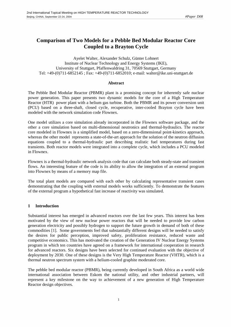
This high temperature gas cooled reactor is based on the recuperative inter-cooled closed loop Braytoncycle using helium as coolant (see in figure 1) [2]. Starting at 1, helium at a relatively low pressureand temperature (1) is compressed by a low-pressure compressor (LPC) to an intermediate pressure (2)after which it is cooled in an inter-cooler to state 3. A high pressure compressor (HPC) thencompresses the helium to state 4. From 4 to 5 the helium is preheated in the recuperator beforeentering the reactor, which heats the helium to state 6. After the reactor the hot high pressure helium isexpanded in a high pressure turbine (HPT) to state 7 after which it is further expanded in a lowpressure turbine (LPT) to state 8. The high pressure turbine drives the high pressure compressor whilethe low pressure turbine drives the low pressure compressor. After the low pressure turbine the heatedhelium is further expanded in the power turbine, which drives the generator, to the pressure 9, which isapproximately the same pressure at 10 and 1. From 9 to 10 the still hot helium is cooled in therecuperator after which it is further cooled in the pre-cooler to state 1. This completes the cycle. Theheat rejected from 9 to 10 is equal to the heat transferred to the helium from 4 to 5.
Figure 1. Schematic diagram of the PBMR high temperature gas cooled reactor Brayton cycle [2].
The complexity associated with the thermal-flow design of the cycle requires the use of a variety ofanalysis techniques and simulation tools. These range from simple one-dimensional models that do notcapture all the significant physical phenomena to large-scale three-dimensional CFD codes that, forpractical reasons, can not simulate the entire plant as a single integrated model [3]. Furthermore, thetreatment of the coupled neutronics and thermal-hydraulics in the reactor core coupled to the PCUnetwork is a complex part which requires a realistic connection of a detailed core model with thenetwork model.One of the most prominent codes that provide a suitable compromise, is the thermal-flow networksimulation code Flownex.
2 Description of Flownex
Flownex is a network simulation code, which encompasses the ability to perform detailed analysis anddesign of complex thermal-fluid systems such as power plants. Flownex solver, described elsewhere[4], is based on the implicit pressure correction method (IPCM) that solves the momentum equation ateach element and the continuity and energy equations at each node in large arbitrary structurednetworks for both steady state and dynamic flow. The solver can deal with both fast and slowtransients. Fast simulation speeds, on standard desktop computers, allow for real time simulations tobe performed. The code has been validated against other codes as well as with experimental data.
With the network approach, a complex thermal-fluid system is represented as a network of one-dimensional elements connected at common nodes (see figure 2). In this figure, elements are denotedby cycles and nodes are denoted by squares. Elements represent components such as pipes,compressors, turbines, heat exchangers, control valves or the pebble bed reactor core.
Recuperator
1
2
3
4
5
6
7
8
910
Reactor
Generator
HPT
LPT
Pre-cooler
Inter-cooler
Powerturbine
HPC
LPC
BPV
COMPARISON OF TWO MODELS FOR A PEBBLE BED MODULAR REACTOR CORE COUPLED TO A BRAYTON CYCLE #D08

3
Figure 2. Example of Flownex network representation [5]
The code features the ability to simultaneously solve multiple gas and liquid networks that areconnected through heat exchangers. It also enables the user to construct re-usable models of complexcomponents or sub-systems such as gas-cooled nuclear reactors and heat exchangers. The reactor andthe heat exchangers are not treated as lumped systems but as distributed systems. The code can alsodeal with conductive heat transfer through solid structures.Advanced rotating model allows for stage-by-stage modeling of compressors and turbines. Otherfeatures of the code are its ability to design PID controllers and control systems.The software can be directly linked with other external computational codes, which can be externallycoupled to it.
3 Characterization of the Flownex core model
The pebble bed reactor core is made up of fuel spheres and passive graphite spheres [6], such as theone shown schematically in figure 3. Each of the fuel spheres that make up the core consists of aninner fuel region with a 50 mm outer diameter made up of coated Uranium dioxide (UO2) particlesimbedded in a graphite matrix. A fuel-free graphite protective layer with an outer diameter of 60 mmcovers the fuel region.
Figure 3. Schematic representation of a fuel sphere [2].
1
8
1110
5 6
9
12
7
4321
109
6 7
11
8
5432
13
1
8
1110
5 6
9
12
7
4321
109
6 7
11
8
5432
13
HTR 2004 Beijing, CHINA, 2004.9

4
Figure 4. Schematic two-dimensional representation of the core of the pebble bed reactor [2].
A schematic two-dimensional representation of the geometry of the reactor core is shown in figure 4.The inner core region contains passive graphite spheres while the outer active core region is filled withfuel spheres. Helium gas enters the top of the reactor core at approximately 500°C. The gas is heatedprimarily through the active core region where heat is generated inside the fuel spheres. Upon leavingthe core at the bottom the hot gas is mixed with gas from the passive region to obtain a fully mixedexit temperature of approximately 900°C.
Figure 5. Graphical representation of the thermal-hydraulic network for the reactor core [2].
The existing model consists of three main parts [7]:• Heat transfer and fluid flow of the gas within the core. The model is based on a discretised two
dimensional axi-symetric network, which consists of any number of control volumes in the axialand/or radial directions as demonstrated in figure 5. The model includes the convective heattransfer between the gas and the surface of a representative sphere in each of the control volumes.However, it only allows for the simulation of the core itself, excluding all core structures, and isbased on a core layout with a homogeneous graphite pebble region at the center and ahomogeneous fuel pebble region in the annulus without a solid central reflector column. Also, itdoes not allow for the addition or extraction of leak flows from the inner or outer perimeter of thecore and the gas inlet and outlet is assumed to be from voids at the very top and the very bottom ofthe core.
COMPARISON OF TWO MODELS FOR A PEBBLE BED MODULAR REACTOR CORE COUPLED TO A BRAYTON CYCLE #D08

5
• Heat conduction within the pebbles. Each of the core control volumes contains a representativepebble for which the heat conduction is modeled in a one-dimensional spherical frame of referencetogether with the convection heat transfer between the gas and the surface of the sphere. Thesphere consists of an outer graphite layer and the inner fuel matrix region, both of which can bediscretised into any number of spherical `onion ring shaped´ control volumes. This allows for thecalculation of the temperature distribution within the pebbles in any region of the core. Thenuclear power generated in the core is distributed with the fuel matrix region only in the form of asource term in the heat conduction equation.
• Nuclear power and decay heat generation. The model is based on a zero-dimensional point-kinetics approach and calculates a single normalized power level for the core as a whole based onreactivity feedback equations taking into account the average fuel and moderator temperatures,xenon concentration and the control rod settings. The total reactor power is distributed among theaxial layers of the core based on a fixed normalized power distribution profile. However, it doesnot account for any radial power distribution profile on each of the different axial levels. Figure 6shows a schematic representation of the interaction between the three models mentioned.
Figure 6. Schematic illustration of the interaction between the three models [2].
The purpose of this model was not to do detailed reactor design, but rather to allow for the integratedsimulation of the reactor together with the PCU within acceptable computer simulation times. Hence,the requirement for this existing model was to provide quick results of the main flow and heat transferphenomena in the core only, in order to obtain boundary values for the simulation of the rest of thePCU [7].The phenomena that cannot be simulated in the existing model include the following:• The presence of a central reflector column that implies that the core itself has an annular rather
than a cylindrical shape.• The addition and extraction of gas via purpose provided channels and/or leak paths along the inner
or outer perimeters of the core.• The simulation of heat transfer and fluid flow through porous and solid core structures
surrounding the core.• The simulation of fluid flow and heat transfer, including radiation and natural convection, in
purpose provided cavities between core structures with a two-dimensional rather than one-dimensional nature.
• The ability to take into account variations in porosity throughout the core.• The ability to specify normalized radial power distribution profiles within the different axial layers
in the core.• The ability to account for heat generation that may occur in any of the core structures.
Therefore, a need exists for the development of a more comprehensive pebble bed reactor model thatcan still provide with integrated plant simulations, but includes the phenomena listed above.
HTR 2004 Beijing, CHINA, 2004.9
6
4 Description of an alternative (WKIND) core model
The core model built in into Flownex describes the reactor mainly like a point without detailedconsideration of changes in power distribution during reactivity transients (e. g. by control rodmovement, strong temperature changes or spatial changes in xenon distribution). These effects canonly be regarded by solving the space dependent neutron diffusion equation together with an adequatemodel for calculating the temperatures of active core and reflector zones. Furthermore, it is veryimportant to model the detailed heat transfer from fuel zone in the coated particle to the graphitematrix and finally to the coolant gas since the fuel temperature is mainly responsible for the negativereactivity feedback and a homogeneous model under-estimates the fuel temperature andcorrespondingly over-estimates the power increase for fast reactivity transients.
As several verified core models for coupled neutronics and thermal-hydraulics exist, it is obviouslyneeded to couple such stand alone core models with a corresponding network for the PCU to get therealistic boundary conditions and core-PCU interaction for the simulation of operational andaccidental transients. Presently at IKE two programs for core models are available: WKIND andRZKIND [8].
WKIND is a one-dimensional neutronics thermal-hydraulics code which solves the one group neutrondiffusion equation in axial direction based on a set of prepared cross sections which regard spectrumeffects from fuel, moderator, reflector (via bucklings), control rods, small absorber spheres (SAS) andxenon. The thermal-hydraulics part regards the average axial fuel, moderator and gas temperaturedistribution in the core as well as the reflector temperature distribution. An important feature is thedetailed model for the heat transport from fuel in the coated particle to the moderator. For fasttransient this is very important since the relaxation time for heat transport from the graphite isdominant for the fuel temperature and is therefore responsible for a fast negative feedback via theDoppler effect. The cross section sets used in WKIND will be prepared by the stationary HTRneutronics and thermal-hydraulics system WKIND [9] developed by Framatome ANP GmbH.
RZKIND is the two-dimensional (R,Z) version of WKIND, but with a different solver for theneutronics and the thermal-hydraulics equations. The thermal-hydraulics equations can be solvedalternatively to the original version of RZKIND also by the 2D THERMIX/KNOVEK code . At themoment the detailed fuel temperature model of WKIND is not yet implemented into RZKIND but itwill be done in future. With the core models available several transients can be treated with sufficientaccuracy by the 1D-method WKIND. For a more detailed transient analysis with significant changesin radial and axial power distributions the 2D version RZKIND and if necessary in future also a 3Dversion will be available.
The coupling with the PCU network will be done via an interface with Flownex in order to simulatethe realistic boundary conditions for the core mass flow and the temperature and pressure at the inletnode. The results of the neutronics thermal-hydraulics model serve as the transferred energy from coreto the coolant and the pressure drop.
Both codes were validated against theoretical and experimental results especially for the German AVRReactor and reviewed by German licensing authorities for the HTR-Modul concept.
The codes WKIND and RZKIND allow for the following quasi stationary and transient simulations:
• Slow transients due to load changes, start up, shut down;• Analysis of slow xenon transients after load changes;• Slow transients after restart from a hot stand-by;• Slow transients due to recriticality after core heat-up accidents;• Fast transients due to changes of control rod position, SAS position or loss of absorbing
substances;
COMPARISON OF TWO MODELS FOR A PEBBLE BED MODULAR REACTOR CORE COUPLED TO A BRAYTON CYCLE #D08

7
• Fast transients due to changes of coolant mass flow;• Fast transients due to changes of coolant inlet temperature;• Fast transients due to ingress of moderating substances (e. g. water);• Fast transients due to reactivity increase because of compression of the pebble bed.
Once these codes are coupled with a network model, the parameters: coolant inlet temperature andcoolant mass flow through the core are not specified in the WKIND or RZKIND input, but are givenfrom Flownex. The time dependant control rod or SAS absorber position (or any other externalreactivity event) will be specified in the core model input description. The outlet temperature andpower of the core will be transmitted to the Flownex model. If there are actions initiated by the reactorprotection system, they can be formulated by the core model input description (e. g. scram by too highreactor power or exceeding of maximum outlet temperature) or by the interface core model – Flownexor by the input data tables of diverse Flownex elements (e. g. predefined set of time points for openingvalves etc.). With these features a realistic simulation of diverse operational and accidental transientscan be formulated and executed by the coupled Flownex-WKIND (RZKIND) model. Pre-condition fora successful coupled calculation is a consistency of the core parameters and the network parametersfor the initial conditions of the transient and a synchronous solving of the core model and networkequations.
5 Coupling of Flownex Power Conversion Unit model with an alternative core model
A system code consisting of the dynamic systems code Flownex and the neutron kinetic/dynamic codeWKIND has been created through the use of an independent software component. The main goal ofthe design of this coupling component was to develop a software solution, which enables a couplingbetween the two before mentioned applications as well as having the opportunity to couple arbitrarycomponents with Flownex.
The basic coupling technique is a time step based data exchange. After the initialization sequence thetwo applications alternately calculate the results for a distinct time step. Each application is interruptedafter one time step, so that the data can be read from the coupling component. Hereafter the data isprocessed and transferred to the second application, which is now able to calculate the next time step.As long as the calculation proceeds, the data is transferred back to the first application.
In order to enable such a time step based data exchange, the participating applications have to providesuitable interfaces, that can be used within a software component. Flownex and WKIND providedifferent interfaces, which are described more in details as following:
• Flownex: Flownex and an external component interact by means of a memory map file. Methodsfor the usage and handling of such a memory map file are provided by the so called Windows®API (application programming interface). The Windows® API is an inherent part of theWindows® operating system. In order to enable the interaction of two applications by means of amemory map file, the Windows® API provides a global access point for the file. The input andoutput variables stored in that file are defined within Flownex.
• WKIND: The interface for data exchange provided by WKIND is a file based mechanism. WhenWKIND is initialized a file is created. This file contains the time step size, the inlet temperature,the relative coolant mass flow, the control rod position and the power. A character at the beginningof the file indicates whether WKIND or Flownex is the active application.
As Flownex provides only with the access to the variables of a model, it was still necessary to find aproper substitute for the reactor core. In this case a pipe was used, to replace the reactor core withinthe Flownex model. The pressure drop of the pipe was adapted according to the reactor model. Theinlet temperature and the mass flow at the pipe entry are used for generating the input for WKIND.
HTR 2004 Beijing, CHINA, 2004.9
8
It simulates the heat up of the coolant as in the core model for the actual time step. The transientsimulation of the coupled system begins with starting the Flownex transient until the initial stationaryconditions are reached. In parallel the WKIND program which calculates also the stationary initialconditions is started. Afterwards both programs solve their equations for the next time step alternately.The time step size is determined by the WKIND time step specification.
6 Results
The following section will present results generated with the Flownex PCU network coupled with theFlownex integrated pebble bed core, compared to corresponding results generated using the sameFlownex PCU network but coupled with the WKIND core model. Furthermore coupled Flownex-WKIND simulations will be presented for a fast reactivity transient by rapid withdrawing all controlrods without shutdown and a reactivity transient due to withdrawing of control rods and shutdown(control rod insertion and load rejection after scram signal).
The cases are presented as following: first, a short description of the problem that was modeled isgiven. Second, the main interesting results are presented and compared to results obtained with thealternative core model for the first example and discussed for all examples.
6.1 Load rejection
DescriptionIn the first transient a load rejection case is simulated. Full load rejection due to the loss of grid poweris one of the most severe load control scenarios for a power plant [1]. Initially the plant operates atmaximum power and in less than one second the generator load is instantaneously reduced to zero.The shaft directly goes into over speed, and thus it is necessary to quickly reduce the power output ofthe power turbine to prevent the generator from over speeding. The generator speed is thereforecontrolled by opening the Gas Cycle Bypass Valve (GCBV). This valve connects the points of thehighest and lowest pressure within the system and reduces the overall system pressure ratio and thusalso the power output. The GCBV is a quick acting, open-close valve. After the power output has beenreduced, the GCBV is closed again to maintain stable operation.In the load rejection of the design configuration simulated here, the grid power is reduced from fullload (=111.578 MW) to 10 MW.
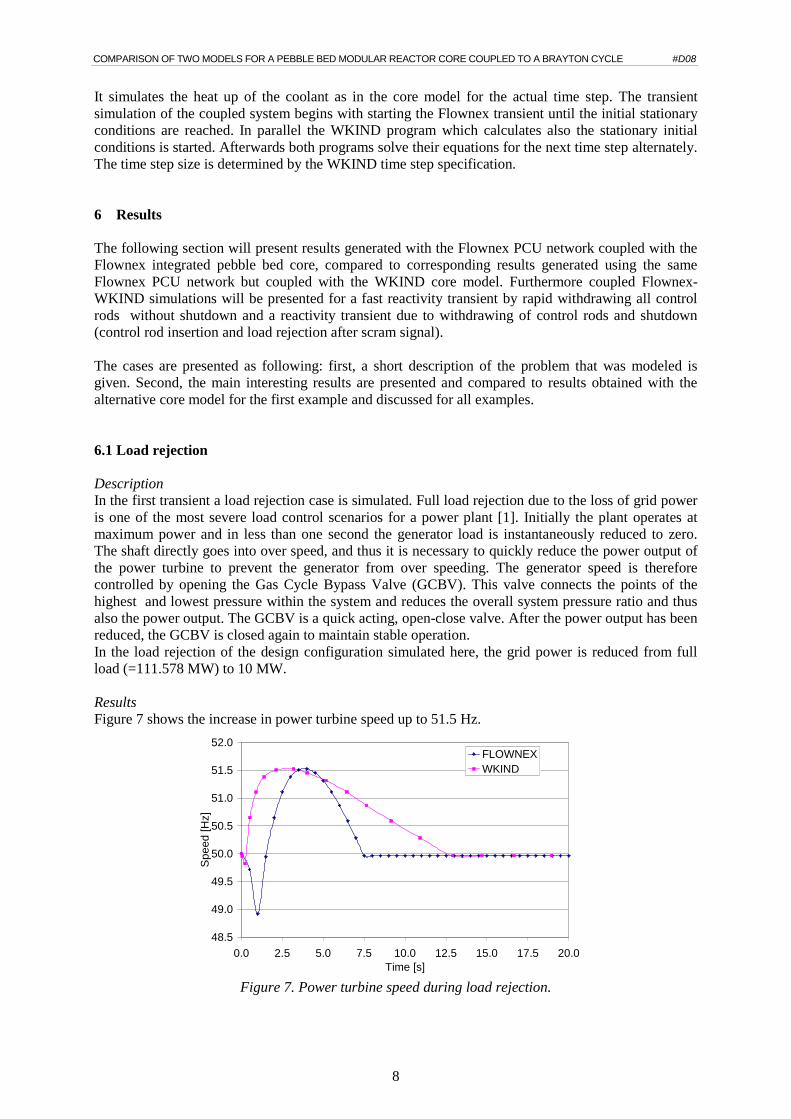
ResultsFigure 7 shows the increase in power turbine speed up to 51.5 Hz.
48.5
49.0
49.5
50.0
50.5
51.0
51.5
52.0
0.0 2.5 5.0 7.5 10.0 12.5 15.0 17.5 20.0Time [s]
Spe
ed [H
z]
FLOWNEXWKIND
Figure 7. Power turbine speed during load rejection.
COMPARISON OF TWO MODELS FOR A PEBBLE BED MODULAR REACTOR CORE COUPLED TO A BRAYTON CYCLE #D08
9
From figure 7 it can be seen that the controller managed successfully to reduce the power turbine overspeed to 1.5 Hz in both models. Both models reach the same degree of over speed. In the systemutilizing a Flownex pebble bed reactor model, the shaft reaches the nominal value of the rotationalvelocity (50 Hz) after 7.5 seconds, whereas in the alternative model, the speed returns to operate at itsnominal value after 12.9 seconds after load rejection.
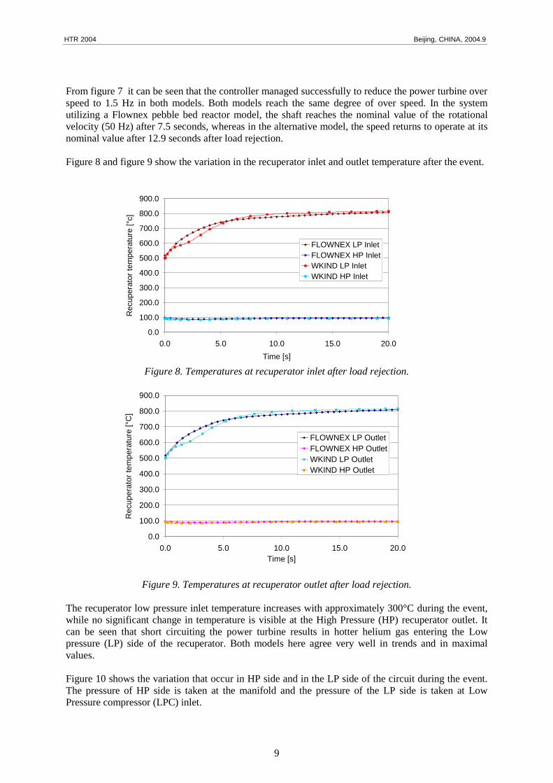
Figure 8 and figure 9 show the variation in the recuperator inlet and outlet temperature after the event.
Figure 8. Temperatures at recuperator inlet after load rejection.
Figure 9. Temperatures at recuperator outlet after load rejection.
The recuperator low pressure inlet temperature increases with approximately 300°C during the event,while no significant change in temperature is visible at the High Pressure (HP) recuperator outlet. Itcan be seen that short circuiting the power turbine results in hotter helium gas entering the Lowpressure (LP) side of the recuperator. Both models here agree very well in trends and in maximalvalues.
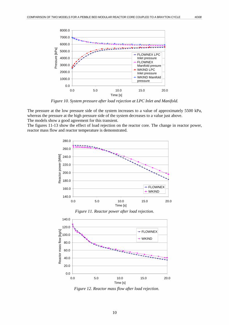
Figure 10 shows the variation that occur in HP side and in the LP side of the circuit during the event.The pressure of HP side is taken at the manifold and the pressure of the LP side is taken at LowPressure compressor (LPC) inlet.
0.0
100.0
200.0
300.0
400.0
500.0
600.0
700.0
800.0
900.0
0.0 5.0 10.0 15.0 20.0Time [s]
Rec
uper
ator
tem
pera
ture
[°c]
FLOWNEX LP InletFLOWNEX HP InletWKIND LP InletWKIND HP Inlet
0.0
100.0
200.0
300.0
400.0
500.0
600.0
700.0
800.0
900.0
0.0 5.0 10.0 15.0 20.0Time [s]
Rec
uper
ator
tem
pera
ture
[°C
]
FLOWNEX LP OutletFLOWNEX HP OutletWKIND LP OutletWKIND HP Outlet
HTR 2004 Beijing, CHINA, 2004.9
10
Figure 10. System pressure after load rejection at LPC Inlet and Manifold.
The pressure at the low pressure side of the system increases to a value of approximately 5500 kPa,whereas the pressure at the high pressure side of the system decreases to a value just above.The models show a good agreement for this transient.The figures 11-13 show the effect of load rejection on the reactor core. The change in reactor power,reactor mass flow and reactor temperature is demonstrated.
Figure 11. Reactor power after load rejection.
0.0
20.0
40.0
60.0
80.0
100.0
120.0
140.0
0.0 5.0 10.0 15.0 20.0Time [s]
Rea
ctor
mas
s flo
w [k
g/s] FLOWNEX
WKIND
Figure 12. Reactor mass flow after load rejection.
0.0
1000.0
2000.0
3000.0
4000.0
5000.0
6000.0
7000.0
8000.0
0.0 5.0 10.0 15.0 20.0Time [s]
Pres
sure
[kPa
]FLOWNEX LPCInlet pressureFLOWNEXManifold presureWKIND LPC Inlet pressureWKIND Manifoldpressure
140.0
160.0
180.0
200.0
220.0
240.0
260.0
280.0
0.0 5.0 10.0 15.0 20.0Time [s]
Rea
ctor
pow
er [M
W]
FLOWNEXWKIND
COMPARISON OF TWO MODELS FOR A PEBBLE BED MODULAR REACTOR CORE COUPLED TO A BRAYTON CYCLE #D08
11
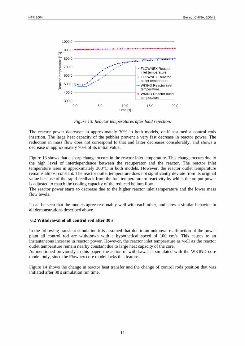
Figure 13. Reactor temperatures after load rejection.
The reactor power decreases in approximately 30% in both models, or if assumed a control rodsinsertion. The large heat capacity of the pebbles prevent a very fast decrease in reactor power. Thereduction in mass flow does not correspond to that and latter decreases considerably, and shows adecrease of approximately 70% of its initial value.
Figure 13 shows that a sharp change occurs in the reactor inlet temperature. This change occurs due tothe high level of interdependence between the recuperator and the reactor. The reactor inlettemperature rises in approximately 300°C in both models. However, the reactor outlet temperatureremains almost constant. The reactor outlet temperature does not significantly deviate from its originalvalue because of the rapid feedback from the fuel temperature to reactivity by which the output poweris adjusted to match the cooling capacity of the reduced helium flow.The reactor power starts to decrease due to the higher reactor inlet temperature and the lower massflow levels.
It can be seen that the models agree reasonably well with each other, and show a similar behavior inall demonstrations described above.
6.2 Withdrawal of all control rod after 30 s
In the following transient simulation it is assumed that due to an unknown malfunction of the powerplant all control rod are withdrawn with a hypothetical speed of 100 cm/s. This causes to aninstantaneous increase in reactor power. However, the reactor inlet temperature as well as the reactoroutlet temperature remain nearby constant due to large heat capacity of the core.As mentioned previously in this paper, the action of withdrawal is simulated with the WKIND coremodel only, since the Flownex core model lacks this feature.
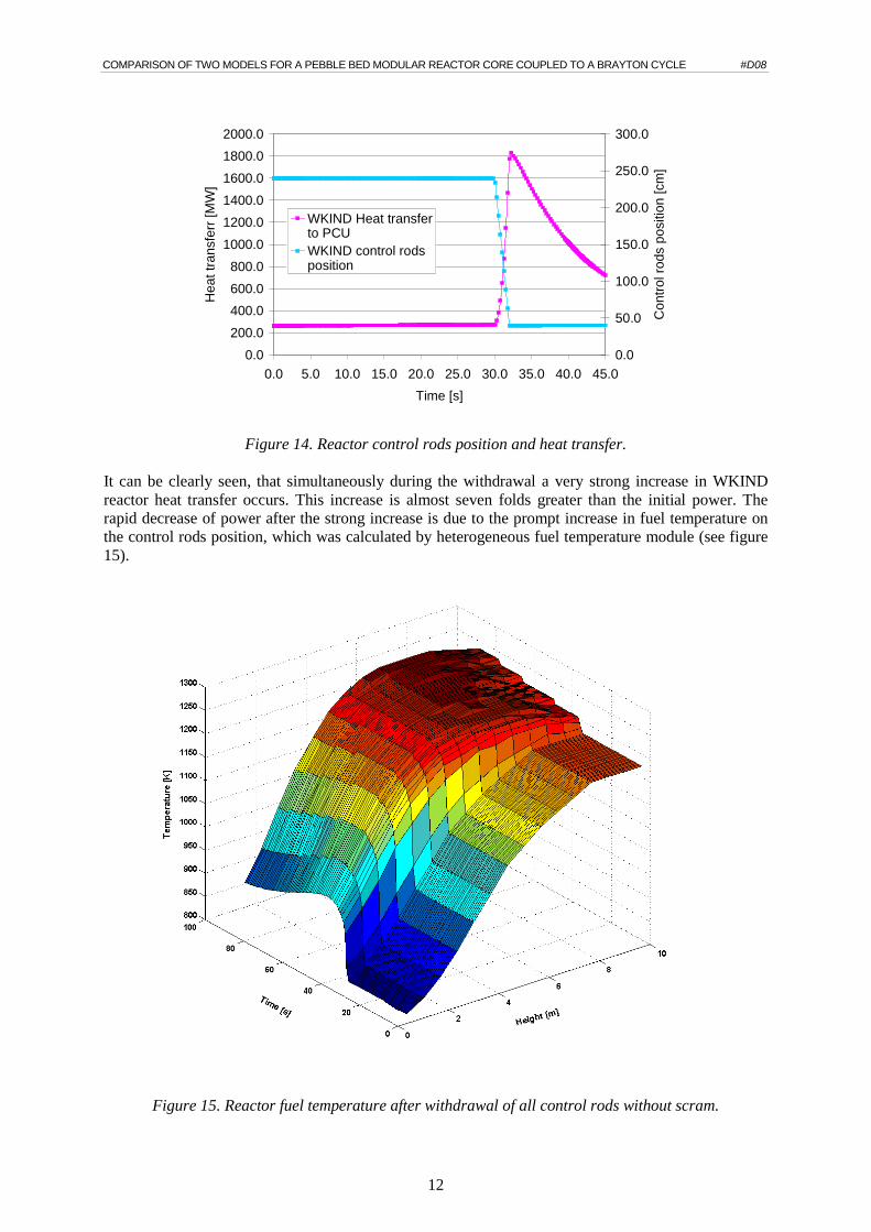
Figure 14 shows the change in reactor heat transfer and the change of control rods position that wasinitiated after 30 s simulation run time.
300.0
400.0
500.0
600.0
700.0
800.0
900.0
1000.0
0.0 5.0 10.0 15.0 20.0Time [s]
Rea
ctor
tem
pera
ture
[°C
]
FLOWNEX Reactorinlet temperatureFLOWNEX Reactoroutlet temperatureWKIND Reactor inlettemperatureWKIND Reactor outlettemperature
HTR 2004 Beijing, CHINA, 2004.9
12
Figure 14. Reactor control rods position and heat transfer.
It can be clearly seen, that simultaneously during the withdrawal a very strong increase in WKINDreactor heat transfer occurs. This increase is almost seven folds greater than the initial power. Therapid decrease of power after the strong increase is due to the prompt increase in fuel temperature onthe control rods position, which was calculated by heterogeneous fuel temperature module (see figure15).
Figure 15. Reactor fuel temperature after withdrawal of all control rods without scram.
0.0
200.0
400.0600.0
800.0
1000.0
1200.01400.0
1600.0
1800.02000.0
0.0 5.0 10.0 15.0 20.0 25.0 30.0 35.0 40.0 45.0Time [s]
Hea
t tra
nsfe
rr [M
W]
0.0
50.0
100.0
150.0
200.0
250.0
300.0
Con
trol r
ods
posi
tion
[cm
]
WKIND Heat transferto PCUWKIND control rodsposition
COMPARISON OF TWO MODELS FOR A PEBBLE BED MODULAR REACTOR CORE COUPLED TO A BRAYTON CYCLE #D08
13
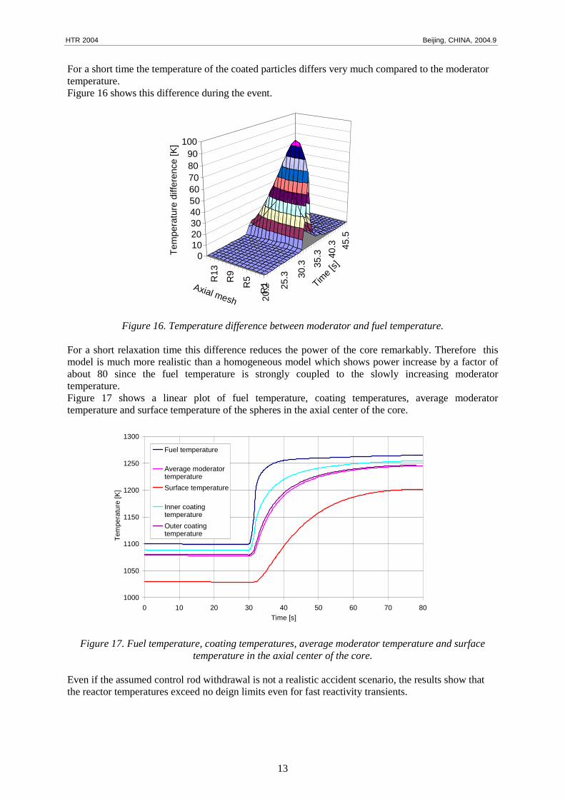
For a short time the temperature of the coated particles differs very much compared to the moderatortemperature.Figure 16 shows this difference during the event.
Figure 16. Temperature difference between moderator and fuel temperature.
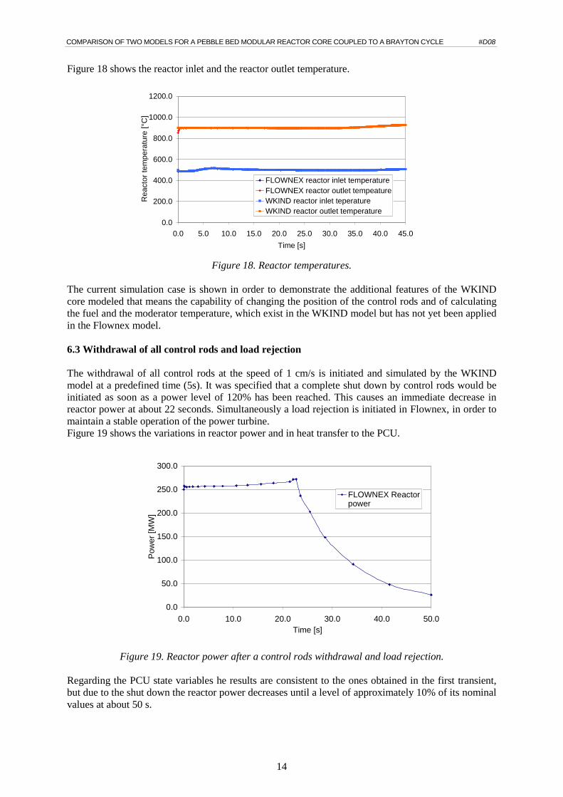
For a short relaxation time this difference reduces the power of the core remarkably. Therefore thismodel is much more realistic than a homogeneous model which shows power increase by a factor ofabout 80 since the fuel temperature is strongly coupled to the slowly increasing moderatortemperature.Figure 17 shows a linear plot of fuel temperature, coating temperatures, average moderatortemperature and surface temperature of the spheres in the axial center of the core.
Figure 17. Fuel temperature, coating temperatures, average moderator temperature and surfacetemperature in the axial center of the core.
Even if the assumed control rod withdrawal is not a realistic accident scenario, the results show thatthe reactor temperatures exceed no deign limits even for fast reactivity transients.
20.2 25
.3 30.3 35
.3 40.3 45
.5
R1R
5R9
R13
0102030405060708090
100
Tem
pera
ture
diff
eren
ce [K
]
Time [
s]
Axial mesh
1000
1050
1100
1150
1200
1250
1300
0 10 20 30 40 50 60 70 80Time [s]
Tem
pera
ture
[K]
Fuel temperature
Average moderatortemperatureSurface temperature
Inner coatingtemperatureOuter coatingtemperature
HTR 2004 Beijing, CHINA, 2004.9
14
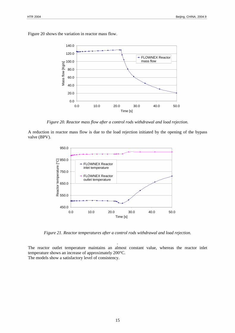
Figure 18 shows the reactor inlet and the reactor outlet temperature.
Figure 18. Reactor temperatures.
The current simulation case is shown in order to demonstrate the additional features of the WKINDcore modeled that means the capability of changing the position of the control rods and of calculatingthe fuel and the moderator temperature, which exist in the WKIND model but has not yet been appliedin the Flownex model.
6.3 Withdrawal of all control rods and load rejection
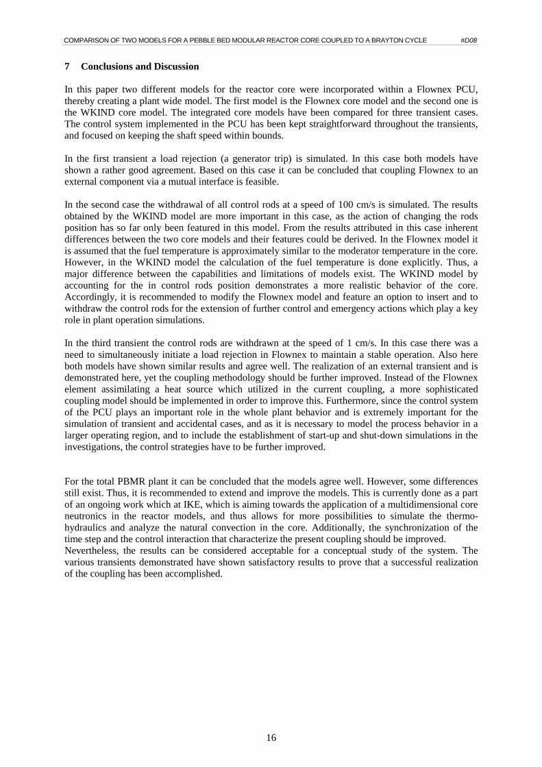
The withdrawal of all control rods at the speed of 1 cm/s is initiated and simulated by the WKINDmodel at a predefined time (5s). It was specified that a complete shut down by control rods would beinitiated as soon as a power level of 120% has been reached. This causes an immediate decrease inreactor power at about 22 seconds. Simultaneously a load rejection is initiated in Flownex, in order tomaintain a stable operation of the power turbine.Figure 19 shows the variations in reactor power and in heat transfer to the PCU.
Figure 19. Reactor power after a control rods withdrawal and load rejection.
Regarding the PCU state variables he results are consistent to the ones obtained in the first transient,but due to the shut down the reactor power decreases until a level of approximately 10% of its nominalvalues at about 50 s.
0.0
200.0
400.0
600.0
800.0
1000.0
1200.0
0.0 5.0 10.0 15.0 20.0 25.0 30.0 35.0 40.0 45.0Time [s]
Rea
ctor
tem
pera
ture
[°C
]
FLOWNEX reactor inlet temperatureFLOWNEX reactor outlet tempeatureWKIND reactor inlet teperatureWKIND reactor outlet temperature
0.0
50.0
100.0
150.0
200.0
250.0
300.0
0.0 10.0 20.0 30.0 40.0 50.0Time [s]
Pow
er [M
W]
FLOWNEX Reactorpower
COMPARISON OF TWO MODELS FOR A PEBBLE BED MODULAR REACTOR CORE COUPLED TO A BRAYTON CYCLE #D08
15
Figure 20 shows the variation in reactor mass flow.
Figure 20. Reactor mass flow after a control rods withdrawal and load rejection.
A reduction in reactor mass flow is due to the load rejection initiated by the opening of the bypassvalve (BPV).
Figure 21. Reactor temperatures after a control rods withdrawal and load rejection.
.The reactor outlet temperature maintains an almost constant value, whereas the reactor inlettemperature shows an increase of approximately 200°C.The models show a satisfactory level of consistency.
0.0
20.0
40.0
60.0
80.0
100.0
120.0
140.0
0.0 10.0 20.0 30.0 40.0 50.0Time [s]
Mas
s flo
w [K
g/s]
FLOWNEX Reactormass flow
450.0
550.0
650.0
750.0
850.0
950.0
0.0 10.0 20.0 30.0 40.0 50.0Time [s]
Rea
ctor
tem
pera
ture
[°C
]
FLOWNEX Reactorinlet temperature
FLOWNEX Reactoroutlet temperature
HTR 2004 Beijing, CHINA, 2004.9
16
7 Conclusions and Discussion
In this paper two different models for the reactor core were incorporated within a Flownex PCU,thereby creating a plant wide model. The first model is the Flownex core model and the second one isthe WKIND core model. The integrated core models have been compared for three transient cases.The control system implemented in the PCU has been kept straightforward throughout the transients,and focused on keeping the shaft speed within bounds.
In the first transient a load rejection (a generator trip) is simulated. In this case both models haveshown a rather good agreement. Based on this case it can be concluded that coupling Flownex to anexternal component via a mutual interface is feasible.
In the second case the withdrawal of all control rods at a speed of 100 cm/s is simulated. The resultsobtained by the WKIND model are more important in this case, as the action of changing the rodsposition has so far only been featured in this model. From the results attributed in this case inherentdifferences between the two core models and their features could be derived. In the Flownex model itis assumed that the fuel temperature is approximately similar to the moderator temperature in the core.However, in the WKIND model the calculation of the fuel temperature is done explicitly. Thus, amajor difference between the capabilities and limitations of models exist. The WKIND model byaccounting for the in control rods position demonstrates a more realistic behavior of the core.Accordingly, it is recommended to modify the Flownex model and feature an option to insert and towithdraw the control rods for the extension of further control and emergency actions which play a keyrole in plant operation simulations.
In the third transient the control rods are withdrawn at the speed of 1 cm/s. In this case there was aneed to simultaneously initiate a load rejection in Flownex to maintain a stable operation. Also hereboth models have shown similar results and agree well. The realization of an external transient and isdemonstrated here, yet the coupling methodology should be further improved. Instead of the Flownexelement assimilating a heat source which utilized in the current coupling, a more sophisticatedcoupling model should be implemented in order to improve this. Furthermore, since the control systemof the PCU plays an important role in the whole plant behavior and is extremely important for thesimulation of transient and accidental cases, and as it is necessary to model the process behavior in alarger operating region, and to include the establishment of start-up and shut-down simulations in theinvestigations, the control strategies have to be further improved.
For the total PBMR plant it can be concluded that the models agree well. However, some differencesstill exist. Thus, it is recommended to extend and improve the models. This is currently done as a partof an ongoing work which at IKE, which is aiming towards the application of a multidimensional coreneutronics in the reactor models, and thus allows for more possibilities to simulate the thermo-hydraulics and analyze the natural convection in the core. Additionally, the synchronization of thetime step and the control interaction that characterize the present coupling should be improved.Nevertheless, the results can be considered acceptable for a conceptual study of the system. Thevarious transients demonstrated have shown satisfactory results to prove that a successful realizationof the coupling has been accomplished.
COMPARISON OF TWO MODELS FOR A PEBBLE BED MODULAR REACTOR CORE COUPLED TO A BRAYTON CYCLE #D08
17
References
1. Ion, S, Nicholls, D, Matzie, R, Matzner, D, “Pebble bed modular reactor the first generation 4reactors to be constructed”, World Nuclear Association Annual Symposium, London, 3-5September, 2003.
2. Greyvenstein, GP, Rousseau, PG, “Basic principles of HTR thermal-hydraulics”, HTR/ECS 2002High Temperature Reactor School, Cadarache, France, November 4-8, 2002.
3. Botha, BW, Rousseau, PG, “Simulation investigation of control options for full load rejection inthe PBMR closed cycle gas turbine power plant”, Proceedings of IGTI Turbo Expo, Amsterdam,June 3-6, 2002.
4. Greyvenstein, GP, “An implicit method for analysis of transient flows in pipe networks“, Int. J.Numer. Meth Eng., 53, 2002, 1127-1143.
5. Coetzee, RV, der Merwe, V, Rousseau, PG, FLOWNEX Version 6 USER MANUAL, M-TechIndustrial, Potchsfstroom, South Africa, 2003.
6. Rousseau, PG, Greyvenstein, GP, “One-dimensional reactor model for the integrated simulation ofthe PBMR power plant”, Proc of 1st International Conference on Heat Transfer, Fluid Mechanicsand thermodynamics, Kruger Park, South Africa, 8-10 April, 2002.
7. Du Toit, CG, Greyvenstein, GP, Rousseau, PG, “A comprehensive reactor model for theintegrated network simulation of the PBMR power plant”, 2003 International Congress onAdvanced Nuclear Power Plants, Cordoba, Spain, May 4-7, 2003.
8. Kindt, T, Hauque, H, “Recriticality of the HTR-Module Power Reactor after hypotheticalaccidents”, Nuc. Eng. Des. 137, 1992, 107-114.
9. Bernnat, W, Feltes, W, “Models for reactor physics calculations for HTR pebble bed modularreactors”, Nuc. Eng. Des. 220, 2003, 331-347.
10. Verkerk, EC, Kikstra, JF, “Comparison of two models for a high temperature reactor coupled to agas turbine”, Nuc. Eng. Des. 220, 2003, 51-65.
HTR 2004 Beijing, CHINA, 2004.9