Embed Size (px)
Citation preview

VOL. 12, NO. 5, MARCH 2017 ISSN 1819-6608
ARPN Journal of Engineering and Applied Sciences ©2006-2017 Asian Research Publishing Network (ARPN). All rights reserved.
www.arpnjournals.com
1580
COMPARISON OF THE STRUCTURAL STABILITY OF GRAVITY
CONCRETE DAMS USING USACE AND USBR STANDARDS
Mohammed Baqer Al-Shadeedi
1 and Ebaa Jihad Hamdi
2
1Department of Civil Engineering, Al-Esra’a University College, Baghdad, Iraq 2Department of Civil Engineering, Al-Nahrain University, Baghdad, Iraq
E-Mail: [email protected] ABSTRACT
Safety factors play an important role in the analysis of structural stability of gravity concrete dams. In this work
the study of these factorswas made according to two standard methods, USBR and USACE, which are varied in the
procedure and calculation of the factors against overturning and sliding, in addition tothe difference in their acceptable
limits. The results obtained from the two standards did not show substantial difference when the dambase is horizontal. To
avoid the sliding phenomena, the dam base must be inclined, the cohesion at the concrete-rock contact must be raised to a
value achieving the desired safety factors; or a passive wedge has to be used at the downstream face to increase the sliding
resistance. The study of stability criteria was done on many virtual dam cases, to obtain the height of water for safe
operation and the strength of concrete, consequently the cohesion required. The value of cohesion required by USACE is
smaller than that of the USBR for the various loading conditions; also the USACE calculations permit water elevations
higher than those for USBR calculations. However, the two standards use the same procedure to evaluate the stresses in the
mass of the dam. The behavior of the dam has been modeled and analyzed using analytically 2-dimensional gravity method
and FEM with the help of ABAQUS software package in order to ensure the safe performance of the dam. Stresses were
found acceptable in all profiles, where it is important to prevent undesirable tensile stresses at the heel, and to avoid
crushing at the toe.
Keywords: concrete, gravity, dam, stability, stress, sliding, overturning.
INTRODUCTION
Concrete gravity dam is a solid structure built of
mass concrete material; therefore, it maintains its stability
against all imposed forces from geometric shape, mass and
strength of concrete. The study will show the effect of
various loading combinations on the stability and stress
analysis of many virtual profiles of gravity dams with
normal water height of 30m and maximum water height of
33.6m; so to compare the stability methods and stress
analysis procedure used by two standards methods, USBR
and USACE.
The section of concrete gravity dam should be
chosen in such a way that it is the most economic section
and fulfills all the conditions and requirements of stability.
The preliminary cross-section of the concrete
gravity dam (elementary section) has a triangular shape in
the beginning of the design. Many configurations will be
made on this profile to achieve further structural stability.
These configurations are: top width, freeboard, batter at
upstream face and suitable slope of downstream face. One
of the most essential and important modifications affecting
the stability of the dam is the slope of concrete-rock
contact surface. In some conditions it may be appropriate
to include downstream passive wedge resistance as a
further component of the resistance of sliding which can
be mobilized. The presence of such passive wedge
resistance, which will be taken into account in this project,
leads to increase the weight of the dam section. The effect
of cohesion and angle of friction on stability requirements
will be considered in this project. Mean values of the
cohesion (c=200 and c=400kN/m2) is used for planes of
the foundations with broken contact. The angle of friction
used is considered as φ = 45o.
However, in order to prevent tensile stress at the
upstream face and also excessive compressive stress at the
downstream face, the dam cross section is usually
designed so that the resultant of acting forces falls within
the third or half at all elevations of the cross section. The
stability of the concrete gravity dam is represented by the
safety of the structure against the external forces, for
example, the self-weight and water pressure, wind
pressure, uplift pressure, silt pressure, earthquake. These
forces would make the dam unstable when they are large
and causing an overturning, sliding, and tension effects on
the dam. Analysis of the stability is generally conducted at
the dam base (rock-concrete contact) and at selected
planes within the dam. For this type of dam, impervious
foundations with high bearing strength are essential.
A stress analysis of gravity dams is performed by
two methods: gravity method and FEM using ABAQUS
software, to evaluate the magnitude and distribution of
stresses throughout the dam for static and dynamic load
conditions. The main objectives of using F.E.M in this
study are to evaluate the maximum tensile and
compressive stresses and to compute the displacements of
the system when the dam is subjected to usual, unusual
and extreme loading conditions. The seismic response is
evaluated for Ali AL-Gharbi earthquake ground
acceleration data using finite element acceleration time
history method.
Study of stability
In all cases, the geometry of the concrete gravity
dam section is assessed by choosing the optimum cross-
section that takes into account all criteria of stability and
stress analysis.
VOL. 12, NO. 5, MARCH 2017 ISSN 1819-6608
ARPN Journal of Engineering and Applied Sciences ©2006-2017 Asian Research Publishing Network (ARPN). All rights reserved.
www.arpnjournals.com
1581
For new projects, the first step in the design
procedure for a new structure represents the layout design.
This step is followed by stability and stress analysis of the
structure that must be made to evaluate the magnitudes of
the stability (safety) factors and the stress distributions
along the structure.
Layout design
The section of concrete gravity dam should be
chosen in such away that it is the most economic section
and fulfills all the conditions and requirements of stability.
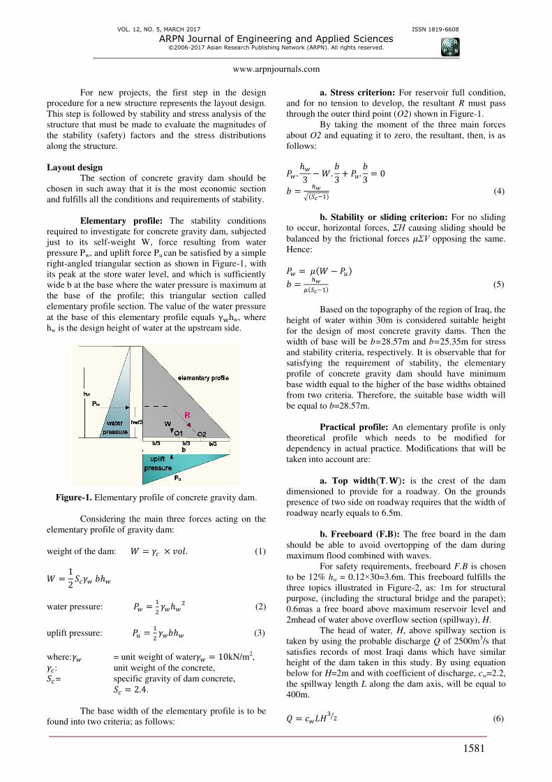
Elementary profile: The stability conditions
required to investigate for concrete gravity dam, subjected
just to its self-weight W, force resulting from water
pressure Pw, and uplift force Pu can be satisfied by a simple
right-angled triangular section as shown in Figure-1, with
its peak at the store water level, and which is sufficiently
wide b at the base where the water pressure is maximum at
the base of the profile; this triangular section called
elementary profile section. The value of the water pressure
at the base of this elementary profile equals γwhw, where
hw is the design height of water at the upstream side.
Figure-1. Elementary profile of concrete gravity dam.
Considering the main three forces acting on the
elementary profile of gravity dam:
weight of the dam: = 𝛾 × 𝑣 𝑙. (1)
= 𝛾 ℎ
water pressure: = 𝛾 ℎ (2)
uplift pressure: = 𝛾 ℎ (3)
where:𝛾 = unit weight of water𝛾 = kN/m2, 𝛾 : unit weight of the concrete,
= specific gravity of dam concrete,
= . .
The base width of the elementary profile is to be
found into two criteria; as follows:
a. Stress criterion: For reservoir full condition,
and for no tension to develop, the resultant R must pass
through the outer third point (O2) shown in Figure-1.
By taking the moment of the three main forces
about O2 and equating it to zero, the resultant, then, is as
follows:
. ℎ − . + . = = ℎ𝑤√ − (4)
b. Stability or sliding criterion: For no sliding
to occur, horizontal forces, ΣH causing sliding should be
balanced by the frictional forces 𝜇ΣV opposing the same.
Hence:
= 𝜇 − = ℎ𝑤𝜇 − (5)
Based on the topography of the region of Iraq, the
height of water within 30m is considered suitable height
for the design of most concrete gravity dams. Then the
width of base will be b=28.57m and b=25.35m for stress
and stability criteria, respectively. It is observable that for
satisfying the requirement of stability, the elementary
profile of concrete gravity dam should have minimum
base width equal to the higher of the base widths obtained
from two criteria. Therefore, the suitable base width will
be equal to b=28.57m.
Practical profile: An elementary profile is only
theoretical profile which needs to be modified for
dependency in actual practice. Modifications that will be
taken into account are:
a. Top width 𝐓. 𝐖 : is the crest of the dam
dimensioned to provide for a roadway. On the grounds
presence of two side on roadway requires that the width of
roadway nearly equals to 6.5m.
b. Freeboard (F.B): The free board in the dam
should be able to avoid overtopping of the dam during
maximum flood combined with waves.
For safety requirements, freeboard F.B is chosen
to be 12% hw = 0.12×30=3.6m. This freeboard fulfills the
three topics illustrated in Figure-2, as: 1m for structural
purpose, (including the structural bridge and the parapet);
0.6mas a free board above maximum reservoir level and
2mhead of water above overflow section (spillway), H.
The head of water, H, above spillway section is
taken by using the probable discharge Q of 2500m3/s that
satisfies records of most Iraqi dams which have similar
height of the dam taken in this study. By using equation
below for H=2m and with coefficient of discharge, cw=2.2,
the spillway length L along the dam axis, will be equal to
400m.
= 𝐻 ⁄ (6)

VOL. 12, NO. 5, MARCH 2017 ISSN 1819-6608
ARPN Journal of Engineering and Applied Sciences ©2006-2017 Asian Research Publishing Network (ARPN). All rights reserved.
www.arpnjournals.com
1582
Figure-2. Freeboard configuration.
If the length of spillway L suits with the length of
the dam, it will be considered in design procedure, if not,
the crest of spillway should be lowered to allow the water
passing smoothly to downstream face. Hence, the total
height of the dam, hd including freeboard is considered to
be:
ℎ = ℎ + 𝐹. = + . = . m (7)
c. The upstream face: the upstream face will
usually be vertical. The downstream face will usually be a
uniform slope starting after the curved portion of the
overflow section near the crest. The slope will usually in
the range of 0.7H to 1V, to 0.8H to 1V to meet stress and
stability requirements at the base [28].
The downstream slope that will be taken in this
work can be considered as 1 for vertical and n for
horizontal; where n is considered to be equal to:
= ℎ ℎ 𝑖 ℎ ℎ ℎ = . . = . (8)
The vertical distance from the downstream edge
of the roadway to an intersection with the sloping
downstream face will be equal to 7.64m. The final output
practical profile for all previous consideration is DAM 1A.
The same procedure made on the elementary profile with
base b=25.35m to obtain DAM 1B. These practical
sections (DAM 1A and DAM 1B) are called dams-type 1,
see Table-1.
d. Inclination of concrete-rock contact: is an
important factor providing stability for the structure.
Transversely, the foundation contact in practice and for
more stability should be either horizontal or sloping
upwards toward the downstream face. Longitudinally, the
section should vary smoothly to abrupt changes so to
minimize stress concentration [11].
The incline angle α is usually used to regulate the
φ angle in sliding stability spreadsheets that assume a
horizontal base; to account for any overall inclination of
the rock/concrete interface. However the factor of safety
calculated by assuming a horizontal base with a φ angle
regulated for the geometric inclination failure surface (α)
will be within +/-5% of the true factor of safety value for
the inclined base, as long as the geometric term (α) is
about 6 degrees [13].
To attain more stability of a concrete gravity
dam, and also to obtain the ideal section with less material
and least values of factors of safety; the practice shows
that geometric term α is always taken as counter clockwise
rotation from the horizontal contact surface. Consequently,
this improvement will be applied to section DAM 1B to
have the new section, DAM 2B. Assuming the rise of the
toe by 3m, the resulted geometric inclination α will be
equal to 6.75o, with keeping the slope of the downstream
face as 0.754(H):1(V). Consequently, the vertical distance
from the downstream side of the crest to the point of an
intersection with the downstream slope is changed from
8.61m at DAM 1B to 5.61m at DAM 2B. The same
process will be performed on DAM 1A with the same
angle that produced from DAM 1B, i.e. α = 6.75o, to
obtain new section, DAM 2A. DAM 2A and DAM 2B are
called dams-type 2.
e. Passive resistance wedge: In some
circumstance, it may be suitable to include passive wedge
resistance Pp at downstream face, as a contribution of
sliding resistance. Therefore, a wedge of rock will be
considered to be adjacent to dams-type 1 to produce the
new sections dams-type 3 (DAM 3A and DAM 3B). To
compute the passive resistance force using equation:
= . tan(𝜑 + 𝛼 ) + .𝐴c 𝛼 . − a 𝜑 . a 𝛼 (9)
The parameters in this equation assumed in this
study are: height of wedge = m,𝛼 : (angle of the sliding surface
for wedge)=30,𝛾 = kN/m ,then, = × × ×× = . kN, (cohesion of passive rock
wedge) =0.5MPa, 𝜑 (angle of friction of passive rock
wedge)=30, (the area of the sliding surface for wedge)
=6×1=6m2; passive resistance become: = . kN
.
VOL. 12, NO. 5, MARCH 2017 ISSN 1819-6608
ARPN Journal of Engineering and Applied Sciences ©2006-2017 Asian Research Publishing Network (ARPN). All rights reserved.
www.arpnjournals.com
1583
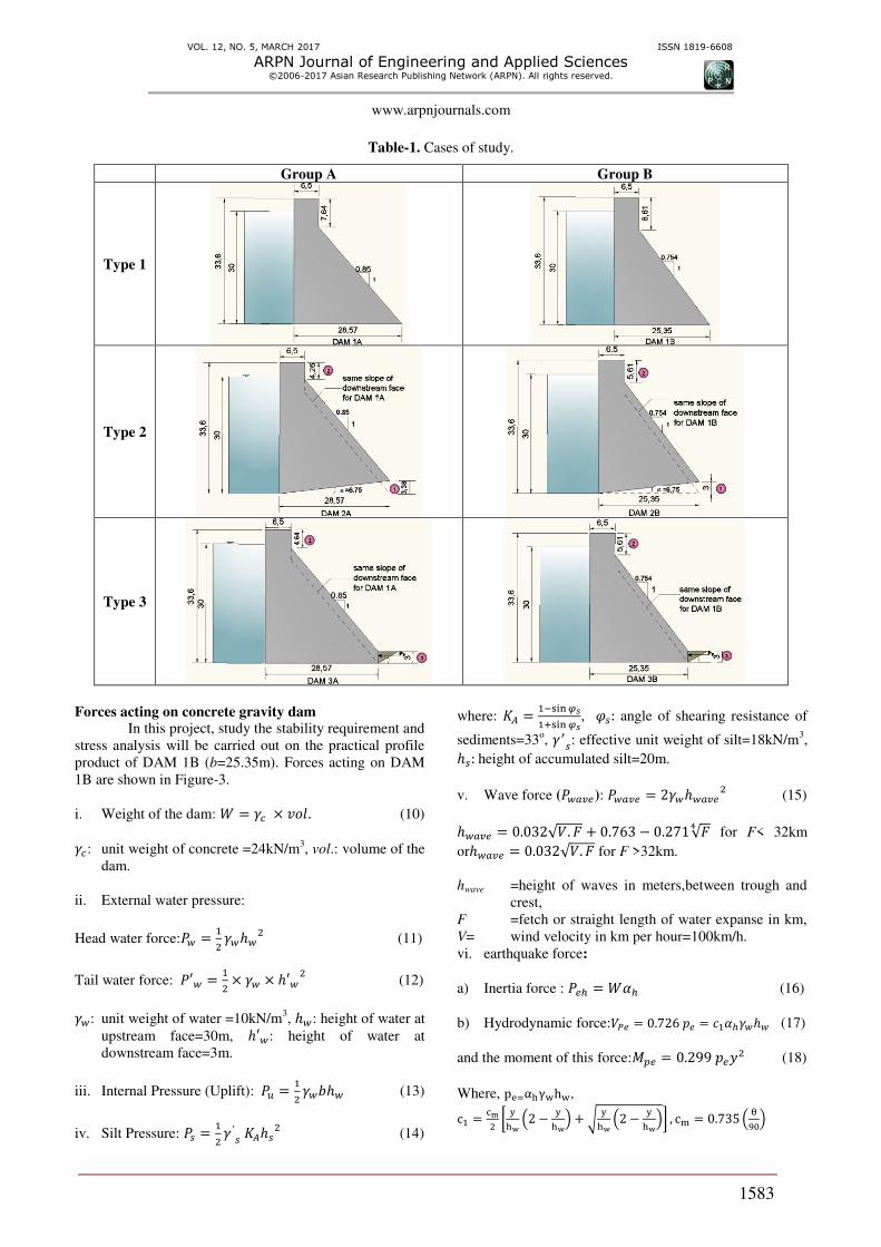
Table-1. Cases of study.
Group A Group B
Type 1
Type 2
Type 3
Forces acting on concrete gravity dam In this project, study the stability requirement and
stress analysis will be carried out on the practical profile
product of DAM 1B (b=25.35m). Forces acting on DAM
1B are shown in Figure-3.
i. Weight of the dam: = 𝛾 × 𝑣 𝑙. (10) 𝛾 : unit weight of concrete =24kN/m3, vol.: volume of the
dam.
ii. External water pressure:
Head water force: = 𝛾 ℎ (11)
Tail water force: ′ = × 𝛾 × ℎ′ (12)
𝛾 : unit weight of water =10kN/m3, ℎ : height of water at
upstream face=30m, ℎ′ : height of water at
downstream face=3m.
iii. Internal Pressure (Uplift): = 𝛾 ℎ (13)
iv. Silt Pressure: = 𝛾 ′ 𝐴ℎ (14)
where: 𝐴 = − 𝜑𝑠+ 𝜑𝑠, 𝜑 : angle of shearing resistance of
sediments=33o, 𝛾′ : effective unit weight of silt=18kN/m
3, ℎ : height of accumulated silt=20m.
v. Wave force ( ): = 𝛾 ℎ (15) ℎ = . √ . 𝐹 + . − . √𝐹4 for F< 32km
orℎ = . √ . 𝐹 for F >32km.
hwave =height of waves in meters,between trough and
crest,
F =fetch or straight length of water expanse in km,
V= wind velocity in km per hour=100km/h.
vi. earthquake force:
a) Inertia force : ℎ = 𝛼ℎ (16)
b) Hydrodynamic force: = . = 𝛼ℎ𝛾 ℎ (17)
and the moment of this force: = . 𝑦 (18)
Where, pe=α γwhw, c = c [ yw − yw + √ yw − yw ] , c = . θ

VOL. 12, NO. 5, MARCH 2017 ISSN 1819-6608
ARPN Journal of Engineering and Applied Sciences ©2006-2017 Asian Research Publishing Network (ARPN). All rights reserved.
www.arpnjournals.com
1584
: Angle in degrees, which the upstream face of the
dam makes with the horizontal=90o.
pe = hydrodynamic earthquake pressure normal to
the face,
c1 = a dimensionless pressure coefficient.
αh = ratio of horizontal acceleration due to
earthquake and the gravitational acceleration, i.e.,
horizontal acceleration factor=0.1.
y = vertical distance from the reservoir surface to
the elevation under consideration=30m
Figure-3. Forces acting on DAM 1B.
Load combination A concrete dam should be designed with regard
to the most rigorous combinations of loads, which have a
reasonable probability of simultaneous occurrence. For
usual (normal) loads the reservoir is typically taken at the
highest normal operating level (hw=30m). For unusual
(flood) loads, the reservoir is taken as the maximum
(peak) level during the inflow design flood event
(hw=33.6m), and can be higher than the crest of the over
flow concrete dam. For the extreme (seismic) load the
reservoir level is typically taken as the usual water level.
Stability requirements and stress analysis
In this project, the study of stability criteria is
made according to two standard methods, US Bureau of
Reclamation, and USBR and US Army corps of
engineering, USACE.
Acceptable safety factors
USBR considered acceptable limits of safety
factors against sliding, as shown in Table-2.
Table-2. Recommended shear friction safety factors in
USBR guidelines.
Sliding plane
Usual
loading
condition
Unusual
loading
condition
Extreme
loading
condition
Dam
concrete/ base
interface
3.0 2.0 1.0
Foundation 4.0 2.7 1.3
The maximum allowable compressive stress in
the concrete should be not greater than the specified
compressive strength divided by 3 for the usual loading
combinations. The maximum allowable compressive stress
for the unusual loading combinations should be not
exceeding specified compressive strength divided by 2.
The allowable compressive stress for the extreme
condition should be not greater than the specified
compressive strength.
USACE considers the acceptable limits of safety
factors of stability that shown in Table-3.
Table-3. Stability and stress criteria according to USACE.
Load
condition
Resultan
t location
at base
Minimu
m sliding
F.S.S
Concrete stresses
Compr
essive Tensile
Usual Middle
1/3 2.0 0.3f'c 0
Unusual Middle
1/2 1.7 0.5f'c 0.6f'c
2/3
Extreme Within
base 1.3 0.9f'c 1.5f'c
2/3
Note: f'c is 1-year unconfined compressive strength of
concrete.
Factor of safety against overturning The factor of safety for overturning F.O.O is not
usually tabulated within other stability factors for USBR
dams, but may be calculated if required by dividing the
total resisting moments by the total moments tending to
cause overturning about the downstream toe.
𝐹. . = ∑ 𝑖 𝑖 𝛴𝑀∑ 𝑖 𝛴𝑀𝑂 > 1.5 (19)
According to USACE, the overturning stability is
calculated by applying all vertical forces, ∑ and the
lateral forces for each loading condition to the dam,
followed by, summing moments ∑ caused by the
resulting forces about toe to calculate the resultant
location, in other wordthe eccentricity e should be less
than b/6; If the resultant acting on the dam at any of its
sections passes outside middle third of the base of the
dam, the dam shall rotate and overturn about the toe.
𝑙 𝑙 𝑖 ′ = ∑ 𝑀∑ 𝑉 (20)
when ∑ = ∑ − ∑
= − ′ (21)
Factor of safety against sliding
Sliding along the dam-rock interface is the most
common failure mode for concrete gravity dams and study
proves that the strength of concrete is key factor in the
design of concrete gravity dams. The sliding factor of
safety is the ratio of the actual frictional shear stresses to
the stresses necessary to achieve equilibrium.
One of the main causes of uncertainty in the
analysis of gravity dam stability is the amount of cohesive
bond present at the dam/foundation interface. For gravity
VOL. 12, NO. 5, MARCH 2017 ISSN 1819-6608
ARPN Journal of Engineering and Applied Sciences ©2006-2017 Asian Research Publishing Network (ARPN). All rights reserved.
www.arpnjournals.com
1585
dams, due to available area of contact, amount of
cohesive, c strength can result in a marked increase in
sliding resistance over the resistance offered by friction
alone (represented by angle of friction, φ). In this thesis
mean values of the cohesion, (c= 200 and 400kN/m2) are
used for planes of the rock-concrete contact in dam
foundation and φ=45o.
Three different methods have been developed to
assess the safety against plane sliding: sliding resistance
method shear friction method andlimit equilibrium
method.
USBR uses shear friction method for the sliding
stability. The shear-friction is based on the calculation of a
safety factor against sliding; this safety factor will be
found by dividing the horizontal force available to resist
the horizontal loads (sliding resistance, SR) by the actual
horizontal forces those are causing the displacement. Its
general form is as follows:
a. Without resistive wedge
𝐹. . = ∑𝐻 (22)
= .𝐴c 𝛼 . − a 𝜑. a 𝛼 + ∑ . tan 𝜑 + 𝛼 (23)
For horizontal plane α=0, 𝐹. . = .𝐴+∑𝑉. a 𝜑∑𝐻 (24)
∑ 𝐻 : Summation of actual horizontal forces, causing
displacement
SR: maximum sliding resistance
ΣV = summation of vertical forces (including
reduction from uplift forces)
A = area of potential failure plane.
c = cohesion. 𝜑 = angle of internal friction.
α = angle between inclined sliding plane developed
and the horizontal (positive for upwards sliding).
(It must be recognized, here, that the angle α
represents the possible angle of failure
irrespective that this plane is concrete-rock
contact or any plane tithing the body of the dam).
b. With resistive wedge
A passive resistance in equation (9) may be
utilized as a contribution for sliding resistance, the
assumption for that is to increase stability against sliding.
Then the factor of safety against sliding will be:
𝐹. . = +Ʃ𝐻 (25)
The limit equilibrium method is the method used
by USACE in order to assess the sliding stability as shown
in Table 2.3. In addition to this, for usual loading, it is
required that the resultant of forces acting on the dam
should fall within the middle third of the dam foundation
contact area to maintain the compressive stresses in the
concrete. For unusual loading conditions, the resultant
must remain within the middle half and for extreme
loading resultant must fall within the base. [28]
a. Without resistive wedge
The limit equilibrium method that used by US
Army Corps of engineers suggests that the factor of safety
against sliding is given by:
𝐹. . = .𝐴+[∑𝑉. 𝛼+∑𝐻. 𝑖 𝛼]. a 𝜑∑𝐻.c 𝛼−∑𝑉. 𝛼 (26)
For horizontal plane, equation of F.S.S using
limit equilibrium method is similar to the equation of shear
friction method, i.e. equation (24)2
b. With resistive wedge
When resisting wedge assumed to be found
adjacent with dam (multi wedges) the factor against
sliding will be found using equation (27).
Then, 𝐹. . = ∑ 𝑖.𝐴𝑖. 𝑠𝛼𝑖+∑ 𝑖.ta 𝜑𝑖𝜂𝛼𝑖𝑖=𝑚𝑖=∑ [∑𝐻𝑖 −∑𝑉𝑖. a 𝛼𝑖]𝑖=𝑚𝑖= (27)
where:
i= the subscript associated with planar segments
along the critical potential failure surface.
m= the number of wedges in the failure mechanism
or number of planes making up the critical
potential failure surface.
The factor 𝜼𝜶𝒊can be determined with equation
below:
𝛼𝑖 = −ta 𝜑𝑖.ta 𝛼𝑖𝐹. .+ 𝛼𝑖 (28)
An initial estimate of F.S.S is used to obtain 𝛼𝑖 is equal to 4.
Safety against compression (crushing) & tension
Gravity method
Safety against crushing and tension is similar in
the way of procedure according in both standard methods
discussed above, USBR and USACE. The comparable
stress values are so close to each other. Table 2.3 will be
used for checking the safety against compression
(Crushing) & Tension for both methods.
a. Safety against compression
A dam may fail by the failure of its materials, i.e.,
the compressive stresses produced may exceed the
allowable stresses, and the dam material may get crushed.
The vertical normal stress distribution at the toe is given
by:
𝜎 𝐷 = ∑𝑉 + (29)

VOL. 12, NO. 5, MARCH 2017 ISSN 1819-6608
ARPN Journal of Engineering and Applied Sciences ©2006-2017 Asian Research Publishing Network (ARPN). All rights reserved.
www.arpnjournals.com
1586
The reference compressive strength in this study
is taken as 25MPa for comparing the resulting stress in the
structure.
b. Safety against tension
The normal stress at the heel is: 𝜎 = ∑𝑉 − (30)
It is evident that if e > b/6, the normal stress of
the heel will be tensile. No tension should be allowable at
any point of the dam under any condition. For no tension
to develop, the eccentricity must be less than b/6. In other
words, the resultant should always lie within the middle
third, Figure-4.
Figure-4. Normal stresses on the base of
concrete gravity dam.
Finite Element modeling
The Finite Element Method (FEM) is a key
technology in the modeling of advanced engineering
systems. It's a numerical and an approximation method for
determining responses (stress, strain, deformation, etc.) of
a body under external loads. Its results will depend upon
element type, mesh size, and mesh configuration.
A three-dimensional problem can be rearranged
(simplified) if it can be treated as a two dimensional (2D)
solid. The dam was considered as a 2D solid, where one
coordinate (z-axis) was ignored. According to the
geometry of the dam, the nature of loading on the dam
makes the dam problem as plane strain problem; therefore,
it is analyzed as plane strain problem using ABAQUS
software. The finite element meshes used in the analysis of
the DAM 1B section consist of 646 nodes and 592
elements, first order, reduced-integration plane strain
elements (CPE4R), Figure-5.
Figure-5. Finite element mesh of DAM 1B.
DAM 1B is 33.6m high and 25.35m wide at the
base of the solid section. The upstream wall is straight and
vertical, and the downstream face with slope of 0.754H:
1V. The depth of the water at the upstream of the dam was
30 meters for usual condition and extreme condition
(when Ali AL-Gharbi earthquake applied), 33.6m at flood
condition (unusual condition). For the purpose of this
study and to make agreement with the practice in dam
construction which requires that dams must be founded on
very strong sound bed-rock, i.e. the foundation is rigid.
The materials of DAM 1B section are assumed to be
homogeneous, isotropic and linear elastic material.
According to [ACI 207.1R-96, for mass concrete], the
tensile strength was estimated to be = . ′ / =. MPa [3]. When ′ is compressive strength of
concrete and it was assumed as 25MPa [18] in this project,
Table-4.
Table-4. Concrete properties of all assumed dams.
Property Concrete Unit
Density 2400 Kg/m3
Elastic modulus 30000 MPa
Poisson's ratio 0.18 -
Allowable Compression
strength 25 MPa
Allowable tensile strength 2.736 MPa
The dam was subject to different loads which
include: gravity load due to self-weight of the dam,
hydrostatic pressure, silt pressure, uplift pressure, seismic
load and hydrodynamic pressure. In this project, finite
element analysis by using ABAQUS program, was carried
out to the same dam section used in two-dimensional
gravity method, DAM 1B, and for three loading
combinations, usual, unusual, and extreme; to investigate
the stresses and deformations under the expected design
loads. For dynamic loading condition, the transverse
ground accelerations of Ali AL-Gharbi, Figure-6, are
applied to all nodes at the base of the dam.
Figure-6. Acceleration - time records of earthquake
hit Ali Al-Gharbi.
RESULTS AND DISCUSSIONS
The same calculations of DAM 1B will be
performed on all virtual sections shown in Table.1 to study
the factors that affecting on stability requirements and
stress analysis according to both USBR and USACE
standards.
Carrying out the stability analysis against
overturning for various loading combinations, DAM 1B
possesses the following values of safety factors:
-2
0
2
0 10 20 30 40 50 60 70
Acc
ele
rati
on
(m/s
2)
Time (sec)

VOL. 12, NO. 5, MARCH 2017 ISSN 1819-6608
ARPN Journal of Engineering and Applied Sciences ©2006-2017 Asian Research Publishing Network (ARPN). All rights reserved.
www.arpnjournals.com
1587
Results of overturning factors Table-5 shows the factors of safety against
overturning according to USBR for three different loading
conditions.
Table-5. Factors of safety against overturning of
DAM 1B according to USBR.
Loading
condition
F.O.O
(Obtained) Standard
Usual 1.58 >1.5
Unusual 1.297 >1.5
Extreme 1.36 >1.5
According to USACE, Table 6 shows the values
of eccentricity for three loading conditions.
Table-6. Values of eccentricity of DAM 1B
according to USACE.
Loading
condition Eccentricity Standard
Usual e = 2.39 e < 4.225
Unusual e = 5.82 e < 4.225
Extreme e = 5.288 e < 4.225
For both standard, USBR and USACE, DAM 1B
is accepted for overturning safety for usual loading
combination and fails for unusual and extreme loading
combination. According to USBR, in order to achieve
safety against overturning for DAM 1B for unusual and
extreme loading conditions, the level of water should be
dropped to suitable elevation, which achieves a safety
factor of overturning equal to 1.5 (𝛴𝑀𝛴𝑀 = . ). Therefore,
the water height should be at level the 30.9minstead of
33.6m for unusual loading condition, and 28.1minstead of
30m for extreme loading condition.
For USACE, like USBR, DAM 1B fails in
unusual and extreme loading conditions. To avoid this
type of failure, the height of water must satisfy the rule
that the resultant of all forces shall intersects the base of
the dam within the middle third, must be calculated. In
other ward, this height of water must achieve that e should
be less or equal b/6 which is equal to 4.225m. The
maximum height of water for unusual loading combination
is 32.05m, and 28.8m for extreme loading combination.
This meansthat USACE allows water levels higher than
USBR method.
Results of sliding factors
Because of the base of DAM 1B is horizontal, the
same results of sliding factor appear for both standard,
USBR and USACE, as shown in Table-7.
Table-7. Factors of safety against sliding of DAM 1B according to USBR & USACE.
Loading
condition Parameters
Sliding factor (Obtained) Standard
USBR USACE USBR USACE
Usual c = 200
&
φ = 45
2.35 2.35 >3 >2
Unusual 1.84 1.84 >2 >1.7
Extreme 1.79 1.79 >1 >1.3
Usual c = 400
&
φ = 45
3.37 3.37 >3 >2
Unusual 2.67 2.67 >2 >1.7
Extreme 2.56 2.56 >1 >1.3
This Table, again, yields the notice, that
according to USBR, DAM 1B fails in sliding for usual and
unusual loading conditions when bond of the concrete-
rock contact is moderately weak (c =200kN/m2). So as to
avoid the sliding, the cohesion must be increased for no
less than 328kN/m2 (then f'c will be about 6.56MPa where
c=0. 05f'c [13]) to achieve F.S.S equal to 3 for usual
loading condition; and 239kN/m2 (f'c=4.78MPa) for
unusual loading condition. However, in USACE, DAM 1B
achieve the requirements of overturning safety for all
loading conditions.
Results of compression and tension
Table-8 illustrates the normal stresses on heel and
toe for DAM 1B; the results show that all stresses remain
safe limits for all loading combinations.
VOL. 12, NO. 5, MARCH 2017 ISSN 1819-6608
ARPN Journal of Engineering and Applied Sciences ©2006-2017 Asian Research Publishing Network (ARPN). All rights reserved.
www.arpnjournals.com
1588
Table-8. Normal stresses on DAM 1B.
Loading
condition
Normal
stresses Obtained (kN/m
2)
Standard (kN/m
2)
Usual At heel
(𝜎 )
414.4 <7500
Unusual 586.5 <12500
Extreme 595.95 <22500
Usual
At toe
(𝜎 )
114.96 (Compression) 0
Unusual -93.1 (Tensile) <5130 (Tensile)
Extreme -66.55 (Tensile) <12824.8(Tensi
le)
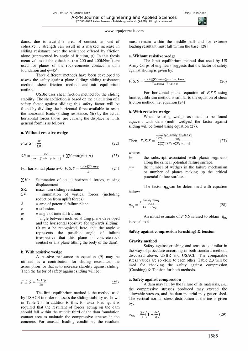
Results of parameters affecting on stability factors
a) Slope of the base of the dam (dams-type 2),
Figure-7 shows the effect of the slop of the base of the
dam on stability factors for three loading condition. The
results show that the upward inclination (counter
clockwise rotation) of the line of the base around an axis
passing through the heel, DAM 2B give more stability
from the normal case of horizontal base, DAM 1B for two
standard, USBR and USACE.
Figure-7. Affect of inclined the base of DAM 1B on
safety factors according USBR and USACE.
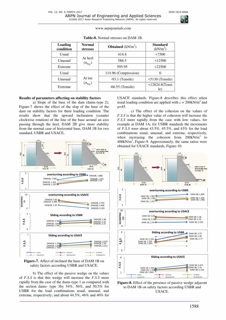
b) The effect of the passive wedge on the values
of F.S.S is that this wedge will increase the F.S.S more
rapidly from the case of the dams-type 1 as compared with
the section dams- type 3by 54%, 56%, and 50.5% for
USBR for the load combinations usual, unusual, and
extreme, respectively; and about 44.5%, 46% and 40% for
USACE standards. Figure-8 describes this effect when
usual loading condition are applied with c = 200kN/m2 and
φ=45.
c) The effect of the cohesion on the values of
F.S.S is that the higher value of cohesion will increase the
F.S.S more rapidly from the case with low values, for
example at DAM 1A; for USBR standards the increments
of F.S.S were about 43.5%, 45.5%, and 43% for the load
combinations usual, unusual, and extreme, respectively,
when increasing the cohesion from 200kN/m2
to
400kN/m2, Figure-9. Approximately, the same ratios were
obtained for USACE standards, Figure-10.
Figure-8. Effect of the presence of passive wedge adjacent
to DAM 1B on safety factors according USBR and
USACE.
DAM1B; 1.585
DAM2B; 1.868
DAM1B; 1.297
DAM2B; 1.53 DAM1B; 1.361
DAM2B; 1.591
1
2
F.O
.O
overturning according to USBR
DAM1B; 2.39
DAM2B; 0.203
DAM1B; 5.82
DAM2B; 2.743 DAM1B; 5.288
DAM2B; 2.698
0
10
EC
CE
NT
RIC
I
TY
overturning according to USACE
DAM1B; 2.356 DAM2B; 2.98
DAM1B; 1.843 DAM2B; 2.33
DAM1B; 1.793 DAM2B; 2.25
0
5
F.S
.S
Sliding according to USBR
DAM1B; 2.356 DAM2B; 3.075
DAM1B; 1.843 DAM2B; 2.29
DAM1B; 1.793 DAM2B; 2.215
0
5
F.S
.S
Sliding according to USACE
USUAL UNUSUAL EXTREME
USUAL/STD UNUSUAL/STD EXTREME/STD
DAM 1B; 1.585 DAM 3B; 1.694
DAM 1B; 1.297 DAM 3B; 1.386
DAM 1B; 1.361 DAM 3B; 1.434
1
2
F.O
.O
overturning according to USBR
DAM 1B; 2.39 DAM 3B; 2.535
DAM 1B; 5.82 DAM 3B; 5.36
DAM 1B; 5.288 DAM 3B; 5.18
0
10
EC
CE
NT
RIC
ITY
overturning according to USACE
DAM 1B; 2.356
DAM 3B; 3.72
DAM 1B; 1.843
DAM 3B; 2.95
DAM 1B; 1.793
DAM 3B; 2.77
0
2
4
F.S
.S
Sliding according to USBR
DAM 1B; 2.356
DAM 3B; 3.471
DAM 1B; 1.843
DAM 3B; 2.74
DAM 1B; 1.793 DAM 3B; 2.576
1
6
F.S
.S
Sliding according to USACE
USUAL UNUSUAL EXTREME
USUAL/STD UNUSUAL/STD EXTREME/STD
VOL. 12, NO. 5, MARCH 2017 ISSN 1819-6608
ARPN Journal of Engineering and Applied Sciences ©2006-2017 Asian Research Publishing Network (ARPN). All rights reserved.
www.arpnjournals.com
1589
Figure-9. Effect of cohesion on F.S.S of DAM 1B USBR.
Figure-10. Effect of cohesion on F.S.S of DAM
1B USACE.
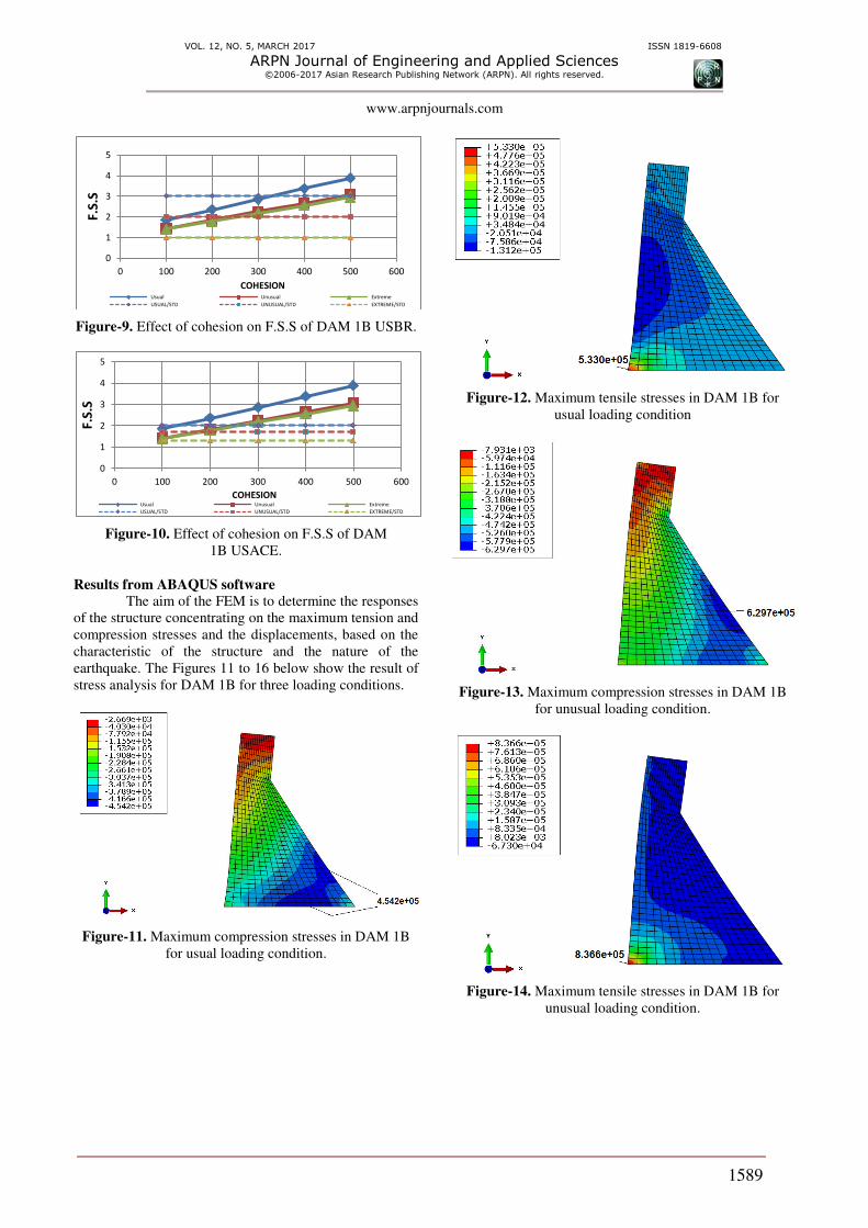
Results from ABAQUS software
The aim of the FEM is to determine the responses
of the structure concentrating on the maximum tension and
compression stresses and the displacements, based on the
characteristic of the structure and the nature of the
earthquake. The Figures 11 to 16 below show the result of
stress analysis for DAM 1B for three loading conditions.
Figure-11. Maximum compression stresses in DAM 1B
for usual loading condition.
Figure-12. Maximum tensile stresses in DAM 1B for
usual loading condition
Figure-13. Maximum compression stresses in DAM 1B
for unusual loading condition.
Figure-14. Maximum tensile stresses in DAM 1B for
unusual loading condition.
0
1
2
3
4
5
0 100 200 300 400 500 600
F.S
.S
COHESION Usual Unusual Extreme
USUAL/STD UNUSUAL/STD EXTREME/STD
0
1
2
3
4
5
0 100 200 300 400 500 600
F.S
.S
COHESION Usual Unusual Extreme
USUAL/STD UNUSUAL/STD EXTREME/STD

VOL. 12, NO. 5, MARCH 2017 ISSN 1819-6608
ARPN Journal of Engineering and Applied Sciences ©2006-2017 Asian Research Publishing Network (ARPN). All rights reserved.
www.arpnjournals.com
1590
Figure-15. Maximum compression stresses in DAM 1B
for extreme loading condition.
Figure-16. Maximum tensile stresses in DAM 1B for
extreme loading condition.
Figure-17. Horizontal crest displacement of DAM 1B
related to ground displacement of extreme condition.
Figure-18. Vertical crest displacement of DAM 1B related
to ground displacement of extreme condition.
For three loading condition, usual, unusual,
extreme; the maximum compression stress for both DAM
1B does not exceed the allowable compressive strength of
the selected concrete which is 25MPa.
The highest value of the tensile stress for DAM
1B was occurred at the heel of the dam; this value is
acceptable, since it is less than 2.736MPa that given in
( = . ′ / = . × / = . MPa). The
positive values represent the tensile stresses, while the
negative values represent the compressive stresses.
According to the extreme loading integrated displacement
results, the maximum horizontal displacement of crest
related to ground displacement towards the downstream
was about 2.25mm, and maximum vertical displacement
was about 0.45mm.
CONCLUSIONS Based on the results of this study, the following
conclusions have been drawn:
It is observable that for satisfying the requirements of
stability, the elementary profile of concrete gravity
dam should have minimum base width equal to the
higher of the base widths obtained from two criteria;
stress criteria and stability criteria. Therefore, the base
width for the reference study case in this project was
equal to b =28.57m, which obtained from stability
criteria. To make the perfect choice of section that
achieves all the requirements of stability with lowest
cost and less material, the section produced from
stress criteria, is taken into account in this project
withb= 25.35m. In both cases the normal height of
water just prior to the dam profile is taken as 30m.
For horizontal plane without passive resistance, F.S.S
in shear friction method,by using USBR standards, is
similar to F.S.S in limit equilibrium method by using
USACE standards.
The main conclusion offeredby this study is that when
evaluating the stability against overturning, the
USACE calculations for eccentricity, - in which the
resultant of all forces shall intersect the base of the
dam within the middle third, or(e<b/6) - those
calculations allow water elevations higher than those
of USBR calculations for F.O.O. As a result and to
avoid the phenomena of overturning during the
operation of the dam in unexpected (unusual and
extreme) loading conditions; the height of water was
to be slightly lowered from the levels at 33.6m and
30.0m, respectively; to achieve the F.O.O of 1.5 for
USBR.
For USACE calculations the value of cohesion, c
=200kN/m2 is found sufficient to achieve sliding
VOL. 12, NO. 5, MARCH 2017 ISSN 1819-6608
ARPN Journal of Engineering and Applied Sciences ©2006-2017 Asian Research Publishing Network (ARPN). All rights reserved.
www.arpnjournals.com
1591
resistance for all groups and types in various loading
combinations: usual, unusual, and extreme.
According to USBR standards, the cohesion at the
concrete-rock contact must be raised to a suitable
value to achieve the value of F.S.S within acceptable
limits. This value of cohesion is related directly to the
compressive strength of concrete. The required
magnitude of cohesion to achieve sliding stability in
usual loading combination is more than that in
unusual loading, while there is no such failure noticed
for extreme combination. Examples are: c = 328 and
239kN/m2 for usual and unusual loading conditions,
respectively, for DAM 1B; and c =204kN/m2 for
DAM 2B in usual loading combination.
The presence of passive resistance wedge at the
downstream face increases sliding resistance with
adequate ratio. This fact is true when comparing
Dams-type 1 with Dams-type 3. The results show that
for USBR standards the existence of passive wedge
increases the sliding factor by about 54%, 56% and
50.5% for usual, unusual, and extreme loading
conditions, respectively; and about 44.5% , 46% and
40% for usual, unusual and extreme loading
conditions for USACE standards.
The results indicate that the stability against
overturning and sliding in usual loading combination
was more than those of the unusual and extreme
loading combinations for both standards USBR and
USACE.
The main objectives of using F.E.M in this study are
to evaluate the maximum tension and compression
stresses and to compute the displacements of the
system when the dam is subjected to usual, unusual
and extreme loading conditions. The stresses obtained
in Dams-type 2 are less than the stresses obtained in
Dams-type 1 with various loading combinations.
Stresses were found acceptable in all profiles, where it
is important to prevent undesirable tensile stresses at
the heel, and to avoid crushing at the toe.
REFERENCES
ABAQUS help, version 6.13.
Abbas Mansouri, MIR Ahmed LashtenNeshaei, Reza
Aghajany. 2011. Fracture Analysis of Concrete Gravity
Dam under Earthquake Induced Loads. Tehran, Iran.
ACI committee 207.1R-96, 1996, Mass Concrete,
American concrete institute.
Ali Anaheet, Abdullah Alzamil, salman Aljamaan. 2012.
Design of Flood Control Gravity Dam in Wadi Banban.
King Saud University Riyadh.
Ali Iqbal. 2012. Probability of Failure for Concrete
Gravity Dams for Sliding Failure. Stockholan, Sweden.
Alsuleimanagha Z, Liang J. 2012. Dynamic Analysis of
TheBaozhusi Dam Using FEM.
Bakenaz A. Zeidan, 2015. Design and Analysis of
Concrete Gravity Dams. Tanta university.
Boberg B and Holm D. 2012. FEM Modeling of Concrete
Gravity Dams. Stockholm, Sweden.
Brian J. Swenty. 1989. Engineering Analysis of Dams.
Bureau of Reclamation. 1976. Design of Gravity Dams.
United States Department of the Interior.
Bureau of Reclamation. 1977. Design Criteria for
Concrete Arch and Gravity Dams. United state
Department of the interior.
Bureau of Reclamation. 1987. Design of Small Dams.
Third edition, United states Department of the interior.
C. Richard Donnelly and Stephen J. Rigbey. 2007. The
Assessment of Sliding Resistance beneath Concrete
Structures. Acres international, Niagara Falls, Canada.
C. Richard Donnelly. 1996. Sliding Stability of Concrete
Gravity Dams. Acres International limited, Niagara Falls
Ontario.
Dr. B.C. PUNMIA, Dr. PANDE B.B.LAL. 2005.
Irrigation and Water Power Engineering. LAXMI
PUBLICATION (P) LID.
G.L Asawa. 2008. Irrigation and water resources
engineering. published by New Age International (P)
LTD, India, New Delhy.
Gérard Degoutte. 2002. Small Dams, Guidelines for
Design, Construction and Monitoring. French Committee
on Large Dams.
Indian standard. 1998. Criteria for Design of Solid Gravity
Dams. Bureau of Indain standard.
Manual Colio Gutierrez. 2013. Shear Resistance for
Concrete Dams. Norwegian university of science and
technology.
Md. Hazrat Ali, Md. RabiulAlam, Md. Naimul Haque,
Muhammad Jahangir Alam. 2011. Comparison of Design
and Analysis of Concrete Gravity Dam.

VOL. 12, NO. 5, MARCH 2017 ISSN 1819-6608
ARPN Journal of Engineering and Applied Sciences ©2006-2017 Asian Research Publishing Network (ARPN). All rights reserved.
www.arpnjournals.com
1592
Miss. Meghna S. Bhalodkar. 2014. Seismic and Stability
Analysis of Gravity Dams. International Journal for
Research in applied science and engineering Technology.
(IJRASET).
P. Novak, A1.B Moffat, C. Nalluri and R. Narayanan.
2007. Hydrodynamic Structures. Fourth edition, published
by Taylor and Francis.
Robert B. Jansen. 1988. Advanced Dam Engineering for
Design, Construction, and Rehabilitation. First edition,
New York.
Robin Fell, Patrick MacGregor, David Stapledon, Graeme
Bell, 2015, 2nd
edition. Geotechnical Engineering of
Dams.
Shamil Abdul Majeed Kadhim. 2014. Optimum
Dimensions of Concrete Gravity Dam with Fluid-
Structure-Foundation Interaction under Seismic Effect.
Doctoral thesis, university of Baghdad.
T Subramani, D. Ponnuvel. 2012. Seismic and Stability
Analysis of Gravity Dams Using Staad Pro. India
US Army Corps of engineering. 2005. Stability Analysis
of Concrete Structures.
US Army Corps of Engineers. 1995. Gravity Dam Design.