Embed Size (px)
Citation preview
Journal for Technology of Plasticity, Vol. 34 (2009), Number 1-2
COMPARISON OF THE INFLUENCE OF FLOW CURVE VARIATION AND FORMING TOOL TOLERANCE IN
MICRO DEEP DRAWING
Zhenyu Hu, Frank Vollertsen BIAS Bremer Institut fuer angewandte Strahltechnik, Germany
ABSTRACT
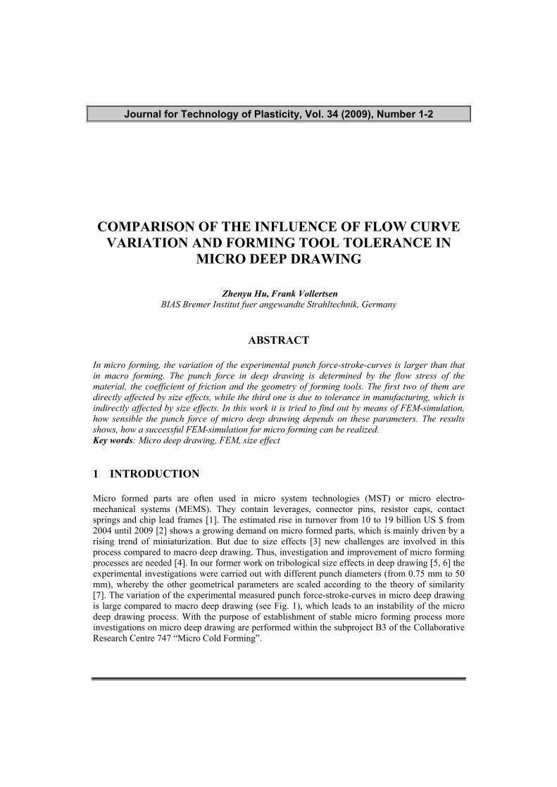
In micro forming, the variation of the experimental punch force-stroke-curves is larger than that in macro forming. The punch force in deep drawing is determined by the flow stress of the material, the coefficient of friction and the geometry of forming tools. The first two of them are directly affected by size effects, while the third one is due to tolerance in manufacturing, which is indirectly affected by size effects. In this work it is tried to find out by means of FEM-simulation, how sensible the punch force of micro deep drawing depends on these parameters. The results shows, how a successful FEM-simulation for micro forming can be realized. Key words: Micro deep drawing, FEM, size effect 1 INTRODUCTION Micro formed parts are often used in micro system technologies (MST) or micro electro-mechanical systems (MEMS). They contain leverages, connector pins, resistor caps, contact springs and chip lead frames [1]. The estimated rise in turnover from 10 to 19 billion US $ from 2004 until 2009 [2] shows a growing demand on micro formed parts, which is mainly driven by a rising trend of miniaturization. But due to size effects [3] new challenges are involved in this process compared to macro deep drawing. Thus, investigation and improvement of micro forming processes are needed [4]. In our former work on tribological size effects in deep drawing [5, 6] the experimental investigations were carried out with different punch diameters (from 0.75 mm to 50 mm), whereby the other geometrical parameters are scaled according to the theory of similarity [7]. The variation of the experimental measured punch force-stroke-curves in micro deep drawing is large compared to macro deep drawing (see Fig. 1), which leads to an instability of the micro deep drawing process. With the purpose of establishment of stable micro forming process more investigations on micro deep drawing are performed within the subproject B3 of the Collaborative Research Centre 747 “Micro Cold Forming”.
2
Journal for Technology of Plasticity, Vol. 34 (2009), Number 1-2
FEM-simulation is a very useful tool for analysis of forming process like micro deep drawing. Using FEM-simulation the effect of parameters on the forming process, for instance the effect of blank holder force on the punch force, can be analyzed. In this work, it is tried using the FEM-simulation to find out, how the other parameters like flow stress and geometry of forming tools affect the punch force in micro deep drawing. The size dependent friction conditions are considered in the FEM-simulations.
Fig. 1 - Variation of the experimental punch force-stroke-curves in micro deep drawing
2 METHOD OF INVESTIGATION
Scaled deep drawing experiments were carried out in former work [5, 6] to investigate the tribological size effect, whereby the punch force-stroke-curves were acquired. The used geometrical parameters are listed in Table 1. Table 1: geometrical parameters of scaled deep drawing
Blank thickness
[mm]
Drawing ratio
Drawn radius [mm]
Drawing clearance
[mm]
Radius of punch [mm]
Punch diameter dP [mm] dP x 2% - dP x 12% dP x 2.8% dP x 10%
50 1 6 1.4 5
20 0.4 2.4 0.56 2
10 0.2 1.2 0.28 1
5 0.1 0.6 0.14 0.5
1 0.02 0.12 0.028 0.1
0.75 0.015
1.5
0.09 0.021 0.075
In order to investigated the variation of the experimental punch force-stroke-curves these scaled deep drawing experiments are further analysed using FEM-simulation in this work. The software ABAQUS 6.6.3 was used for this purpose, whereby for symmetry reasons only one forth of the
3
Journal for Technology of Plasticity, Vol. 34 (2009), Number 1-2
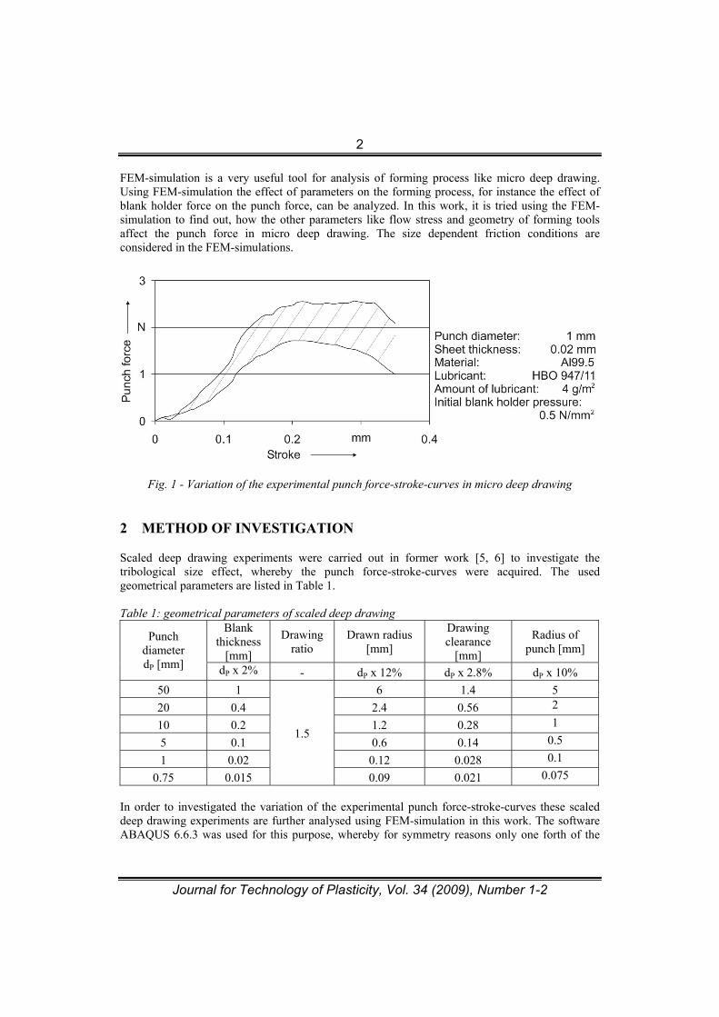
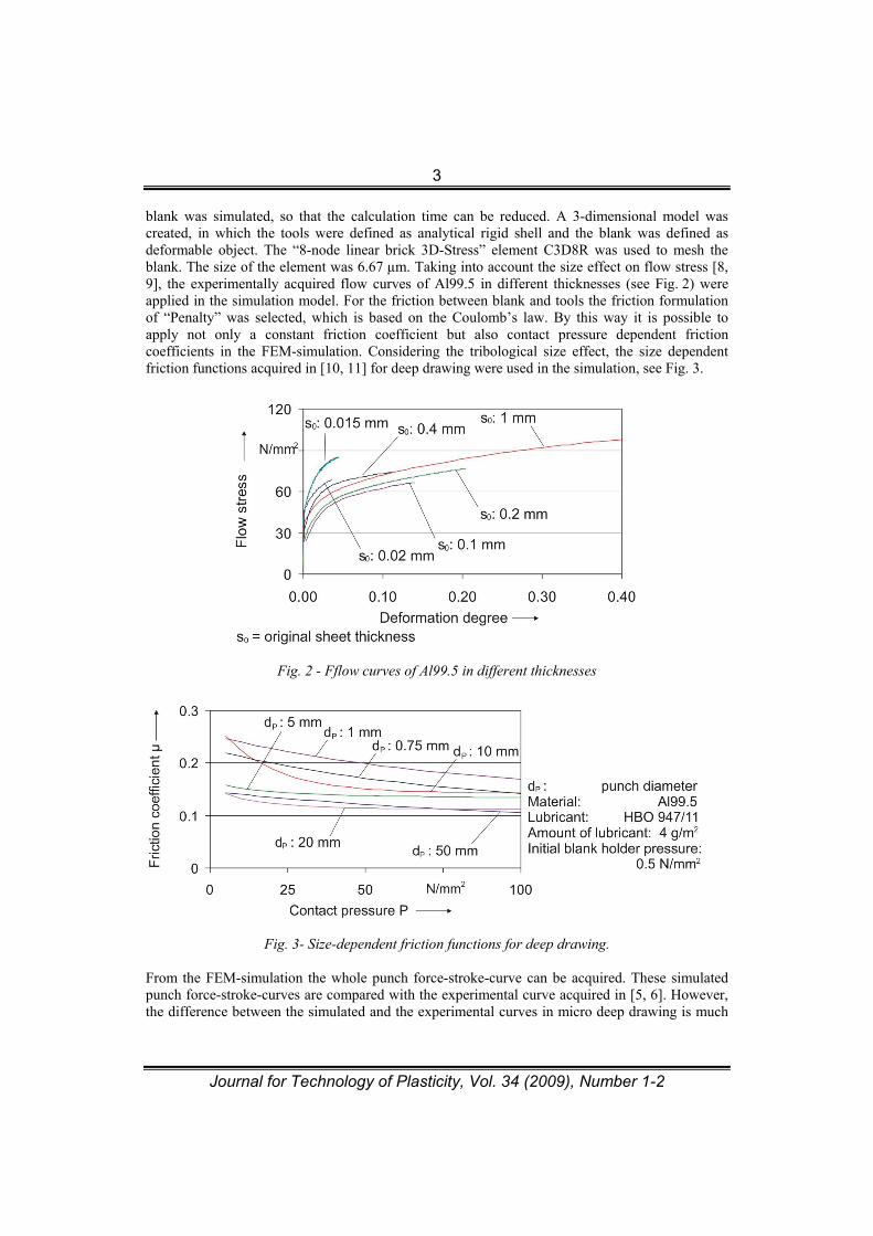
blank was simulated, so that the calculation time can be reduced. A 3-dimensional model was created, in which the tools were defined as analytical rigid shell and the blank was defined as deformable object. The “8-node linear brick 3D-Stress” element C3D8R was used to mesh the blank. The size of the element was 6.67 µm. Taking into account the size effect on flow stress [8, 9], the experimentally acquired flow curves of Al99.5 in different thicknesses (see Fig. 2) were applied in the simulation model. For the friction between blank and tools the friction formulation of “Penalty” was selected, which is based on the Coulomb’s law. By this way it is possible to apply not only a constant friction coefficient but also contact pressure dependent friction coefficients in the FEM-simulation. Considering the tribological size effect, the size dependent friction functions acquired in [10, 11] for deep drawing were used in the simulation, see Fig. 3.
Fig. 2 - Fflow curves of Al99.5 in different thicknesses
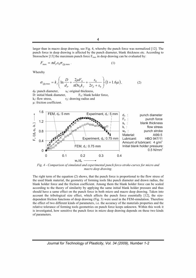
Fig. 3- Size-dependent friction functions for deep drawing. From the FEM-simulation the whole punch force-stroke-curve can be acquired. These simulated punch force-stroke-curves are compared with the experimental curve acquired in [5, 6]. However, the difference between the simulated and the experimental curves in micro deep drawing is much
4
Journal for Technology of Plasticity, Vol. 34 (2009), Number 1-2
larger than in macro deep drawing, see Fig. 4, whereby the punch force was normalized [12]. The punch force in deep drawing is affected by the punch diameter, blank thickness etc. According to Storoschew [13] the maximum punch force Fmax in deep drawing can be evaluated by:
max0max QgPsdF . (1)
Whereby
6.11
2
2ln
0
0
0max
sr
s
kDs
F
d
Dk
Zf
N
PfQg , (2)
dP: punch diameter, s0: original thickness, D: initial blank diameter, FN: blank holder force, kf: flow stress, rZ: drawing radius and µ: friction coefficient.
Fig. 4 - Comparison of simulated and experimental punch force-stroke-curves for micro and
macro deep drawing. The right term of the equation (2) shows, that the punch force is proportional to the flow stress of the used blank material, the geometry of forming tools like punch diameter and drawn radius, the blank holder force and the friction coefficient. Among them the blank holder force can be scaled according to the theory of similarity by applying the same initial blank holder pressure and thus should have a same effect on the punch force in both micro and macro deep drawing. Taken into account the tribological size effect, which affects the punch force essentially [12], the size-dependent friction functions of deep drawing (Fig. 3) were used in the FEM-simulation. Therefore the effect of two different kinds of parameters, i.e. the accuracy of the materials properties and the relative tolerance of forming tools geometries on punch force keeps unknown. Within this work it is investigated, how sensitive the punch force in micro deep drawing depends on these two kinds of parameters.
5
Journal for Technology of Plasticity, Vol. 34 (2009), Number 1-2
3 RESULTS AND DISCUSSIONS 3.1 Sensitivity on geometry of forming tools 3.1.1 Geometrical measurement of forming tools
Due to the tolerance in manufacturing of forming tools, the real geometry of the forming tools has always a certain deviation from the desired geometry. Selecting a suited manufacturing process this deviation can be kept within a small value, so that the absolute geometrical deviation of the forming tools is small for both macro and micro deep drawing. However, the relative geometrical deviation can not be the same, since the absolute dimension of forming tools is minimised in micro deep drawing. In order to investigate the effect of the increasing relative geometrical deviation with minimisation on the forming force, all forming tools were firstly measured precisely in this work.
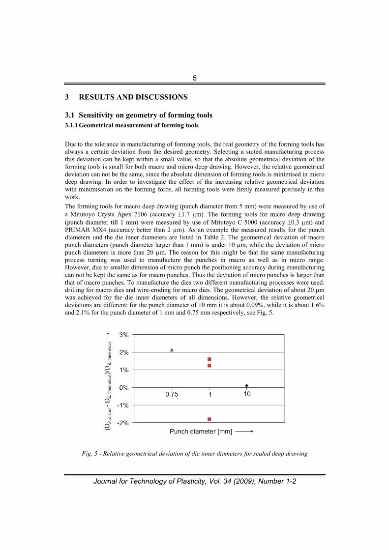
The forming tools for macro deep drawing (punch diameter from 5 mm) were measured by use of a Mitutoyo Crysta Apex 7106 (accuracy 1.7 µm). The forming tools for micro deep drawing (punch diameter till 1 mm) were measured by use of Mitutoyo C-5000 (accuracy 0.3 µm) and PRIMAR MX4 (accuracy better than 2 µm). As an example the measured results for the punch diameters und the die inner diameters are listed in Table 2. The geometrical deviation of macro punch diameters (punch diameter larger than 1 mm) is under 10 µm, while the deviation of micro punch diameters is more than 20 µm. The reason for this might be that the same manufacturing process turning was used to manufacture the punches in macro as well as in micro range. However, due to smaller dimension of micro punch the positioning accuracy during manufacturing can not be kept the same as for macro punches. Thus the deviation of micro punches is larger than that of macro punches. To manufacture the dies two different manufacturing processes were used: drilling for macro dies and wire-eroding for micro dies. The geometrical deviation of about 20 µm was achieved for the die inner diameters of all dimensions. However, the relative geometrical deviations are different: for the punch diameter of 10 mm it is about 0.09%, while it is about 1.6% and 2.1% for the punch diameter of 1 mm and 0.75 mm respectively, see Fig. 5.
Fig. 5 - Relative geometrical deviation of die inner diameters for scaled deep drawing
6
Journal for Technology of Plasticity, Vol. 34 (2009), Number 1-2
Measuring three dies with a same nominal inner diameter of 1.056 mm the measured results show all large deviation (both negative and positive: -1.8%, 1.2% und 1.6%, see Fig. 5) from the desired geometry. Based on the measured results, it can be concluded that the forming tools for micro forming can be manufactured precisely using a suited manufacturing process, whereby the relative geometrical deviation can not be scaled with the process dimension. It increases with minimisation of process dimension.
Table 2: measurements of the forming tools geometries Punch diameter [mm] Die inner diameter [mm]
theoretical actual Deviation �=|theoretical-actual|
theoretical actual Deviation �=| theoretical-actual|
50 49.999 0.001 52.8 52.820 0.020 20 19.999 0.001 21.12 21.133 0.013 10 9.994 0.006 10.56 10.570 0.010 5 4.992 0.008 5.28 5.309 0.029
1.073 0.016 1.069 0.013 1 0.976 0.024 1.056 1.037 0.019
0.75 0.716 0.034 0.792 0.809 0.017
3.1.2 Effect of the geometrical deviations of forming tools on the punch force
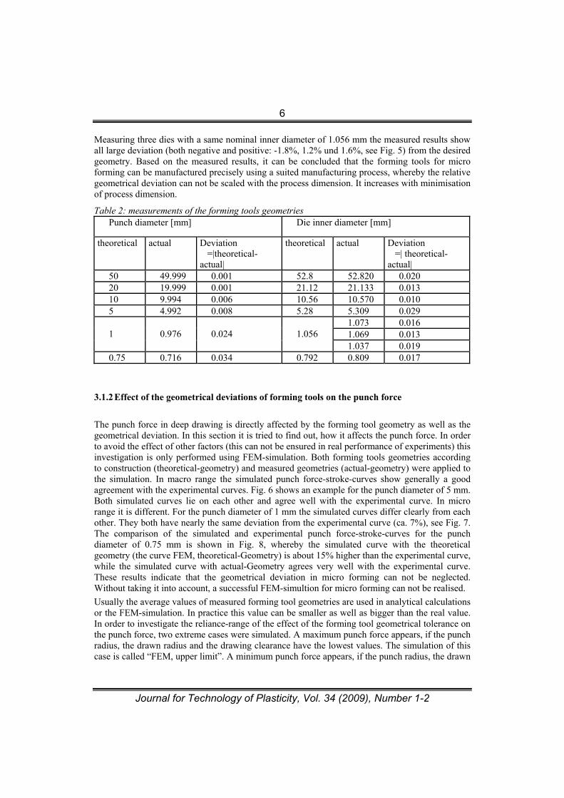
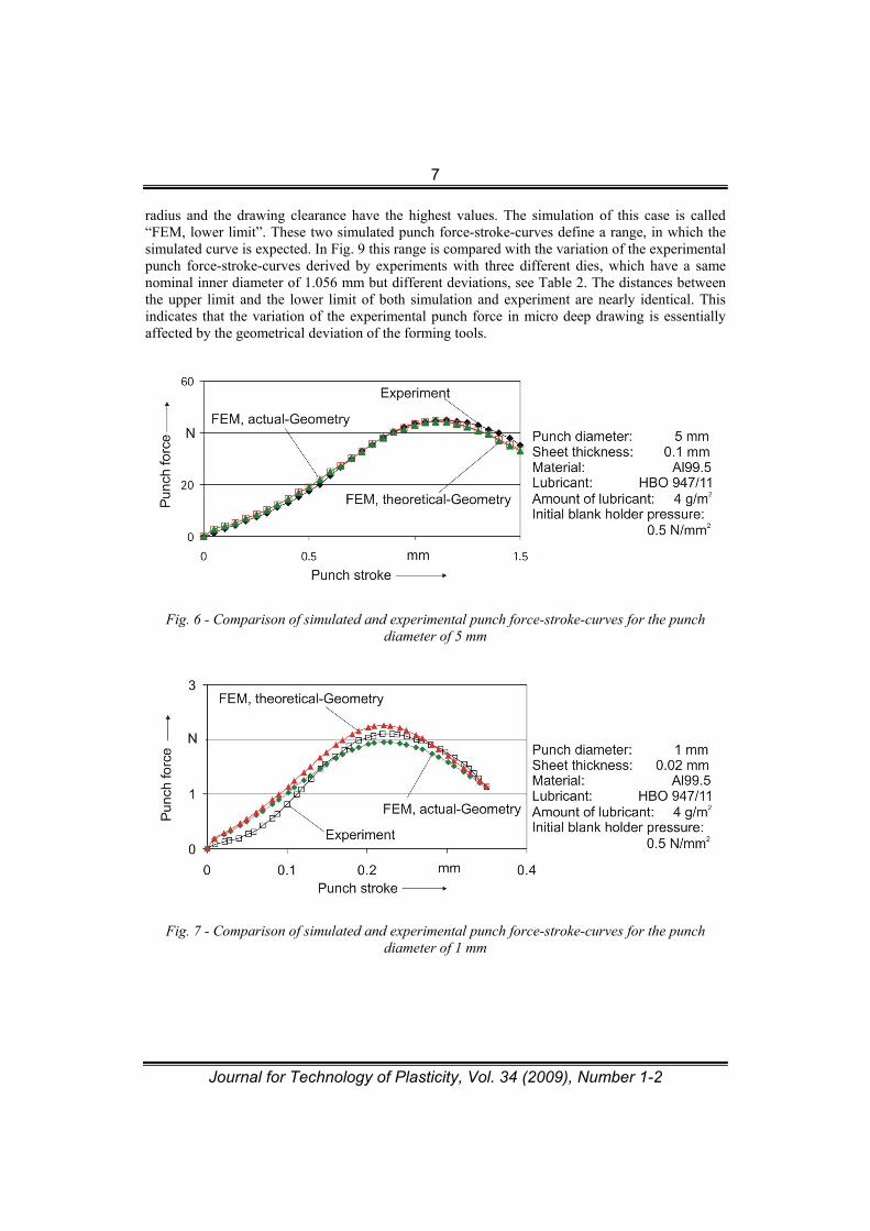
The punch force in deep drawing is directly affected by the forming tool geometry as well as the geometrical deviation. In this section it is tried to find out, how it affects the punch force. In order to avoid the effect of other factors (this can not be ensured in real performance of experiments) this investigation is only performed using FEM-simulation. Both forming tools geometries according to construction (theoretical-geometry) and measured geometries (actual-geometry) were applied to the simulation. In macro range the simulated punch force-stroke-curves show generally a good agreement with the experimental curves. Fig. 6 shows an example for the punch diameter of 5 mm. Both simulated curves lie on each other and agree well with the experimental curve. In micro range it is different. For the punch diameter of 1 mm the simulated curves differ clearly from each other. They both have nearly the same deviation from the experimental curve (ca. 7%), see Fig. 7. The comparison of the simulated and experimental punch force-stroke-curves for the punch diameter of 0.75 mm is shown in Fig. 8, whereby the simulated curve with the theoretical geometry (the curve FEM, theoretical-Geometry) is about 15% higher than the experimental curve, while the simulated curve with actual-Geometry agrees very well with the experimental curve. These results indicate that the geometrical deviation in micro forming can not be neglected. Without taking it into account, a successful FEM-simultion for micro forming can not be realised.
Usually the average values of measured forming tool geometries are used in analytical calculations or the FEM-simulation. In practice this value can be smaller as well as bigger than the real value. In order to investigate the reliance-range of the effect of the forming tool geometrical tolerance on the punch force, two extreme cases were simulated. A maximum punch force appears, if the punch radius, the drawn radius and the drawing clearance have the lowest values. The simulation of this case is called “FEM, upper limit”. A minimum punch force appears, if the punch radius, the drawn
7
Journal for Technology of Plasticity, Vol. 34 (2009), Number 1-2
radius and the drawing clearance have the highest values. The simulation of this case is called “FEM, lower limit”. These two simulated punch force-stroke-curves define a range, in which the simulated curve is expected. In Fig. 9 this range is compared with the variation of the experimental punch force-stroke-curves derived by experiments with three different dies, which have a same nominal inner diameter of 1.056 mm but different deviations, see Table 2. The distances between the upper limit and the lower limit of both simulation and experiment are nearly identical. This indicates that the variation of the experimental punch force in micro deep drawing is essentially affected by the geometrical deviation of the forming tools.
Fig. 6 - Comparison of simulated and experimental punch force-stroke-curves for the punch diameter of 5 mm
Fig. 7 - Comparison of simulated and experimental punch force-stroke-curves for the punch diameter of 1 mm
8
Journal for Technology of Plasticity, Vol. 34 (2009), Number 1-2
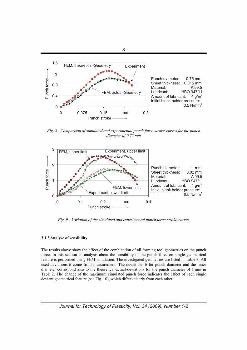
Fig. 8 - Comparison of simulated and experimental punch force-stroke-curves for the punch diameter of 0.75 mm
Fig. 9 - Variation of the simulated and experimental punch force-stroke-curves
3.1.3 Analyse of sensibility
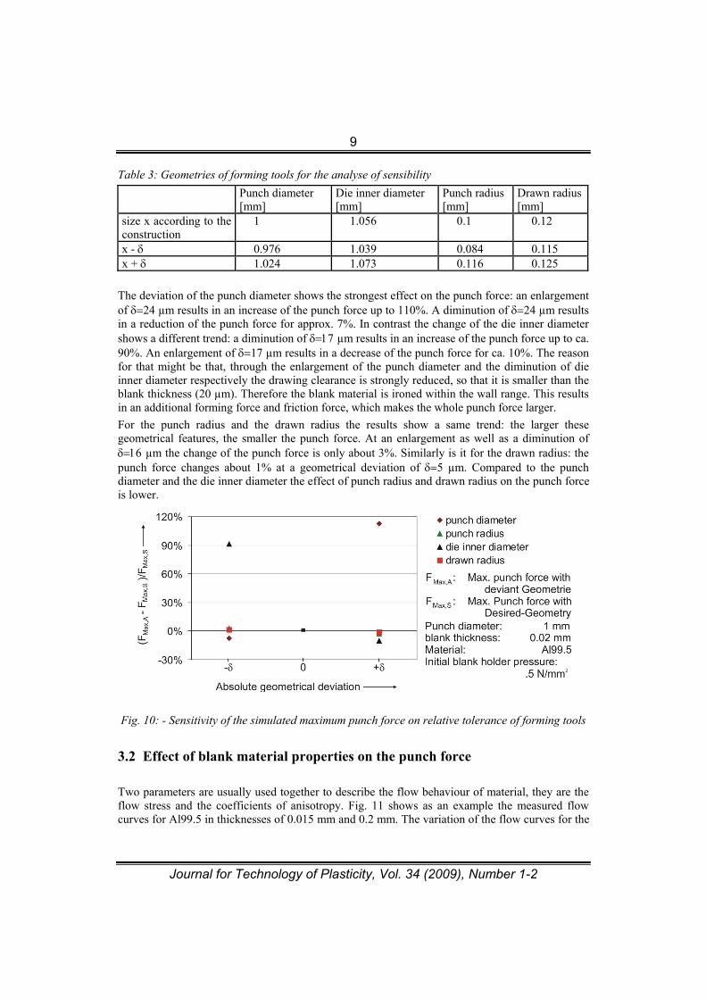
The results above show the effect of the combination of all forming tool geometries on the punch force. In this section an analysis about the sensibility of the punch force on single geometrical feature is performed using FEM-simulation. The investigated geometries are listed in Table 3. All used deviations come from measurement. The deviations for punch diameter and die inner diameter correspond also to the theoretical-actual-deviations for the punch diameter of 1 mm in Table 2. The change of the maximum simulated punch force indicates the effect of each single deviant geometrical feature (see Fig. 10), which differs clearly from each other.
9
Journal for Technology of Plasticity, Vol. 34 (2009), Number 1-2
Table 3: Geometries of forming tools for the analyse of sensibility
Punch diameter [mm]
Die inner diameter [mm]
Punch radius [mm]
Drawn radius [mm]
size x according to the construction
1 1.056 0.1 0.12
x - 0.976 1.039 0.084 0.115 x + 1.024 1.073 0.116 0.125
The deviation of the punch diameter shows the strongest effect on the punch force: an enlargement of 24 µm results in an increase of the punch force up to 110%. A diminution of 24 µm results in a reduction of the punch force for approx. 7%. In contrast the change of the die inner diameter shows a different trend: a diminution of µm results in an increase of the punch force up to ca. 90%. An enlargement of 17 µm results in a decrease of the punch force for ca. 10%. The reason for that might be that, through the enlargement of the punch diameter and the diminution of die inner diameter respectively the drawing clearance is strongly reduced, so that it is smaller than the blank thickness (20 µm). Therefore the blank material is ironed within the wall range. This results in an additional forming force and friction force, which makes the whole punch force larger.
For the punch radius and the drawn radius the results show a same trend: the larger these geometrical features, the smaller the punch force. At an enlargement as well as a diminution of µm the change of the punch force is only about 3%. Similarly is it for the drawn radius: the punch force changes about 1% at a geometrical deviation of 5 µm. Compared to the punch diameter and the die inner diameter the effect of punch radius and drawn radius on the punch force is lower.
Fig. 10: - Sensitivity of the simulated maximum punch force on relative tolerance of forming tools
3.2 Effect of blank material properties on the punch force
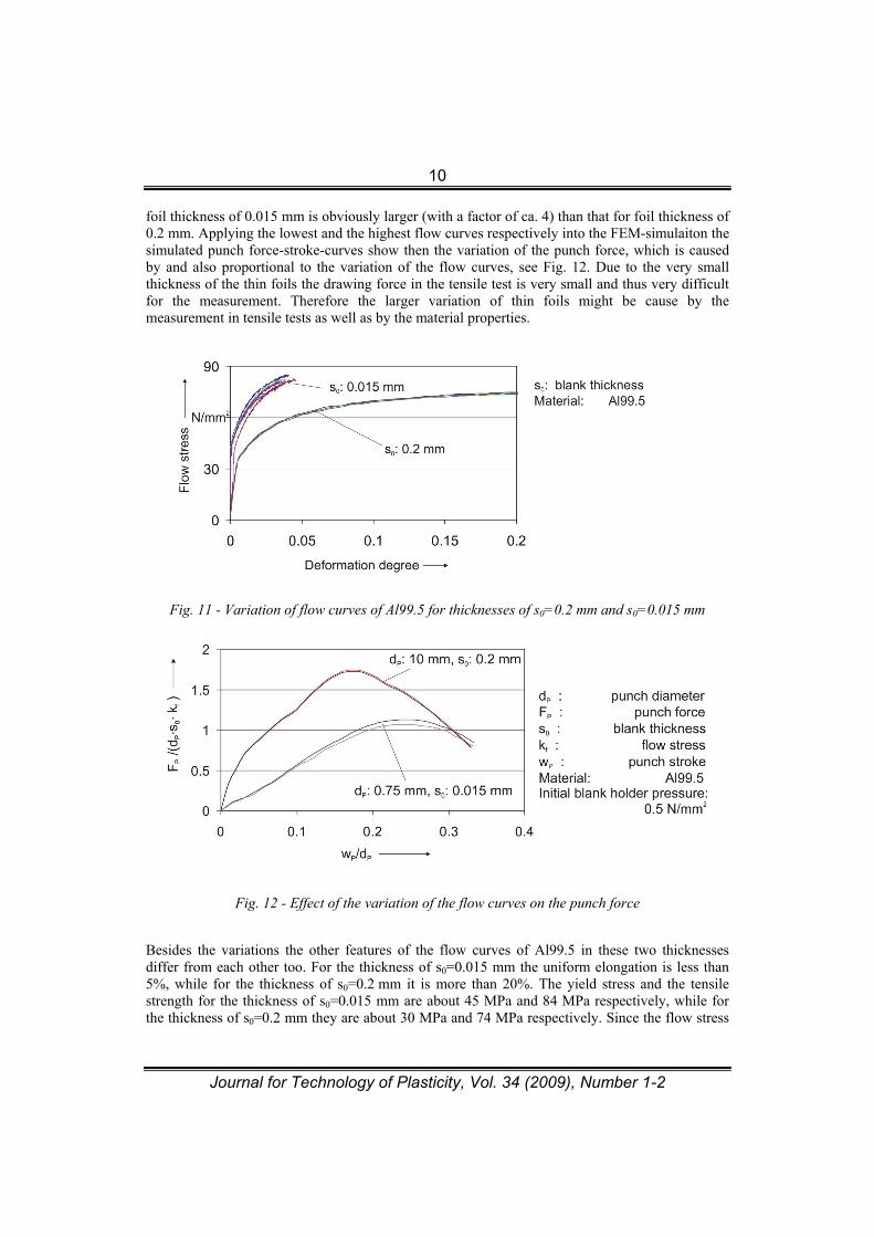
Two parameters are usually used together to describe the flow behaviour of material, they are the flow stress and the coefficients of anisotropy. Fig. 11 shows as an example the measured flow curves for Al99.5 in thicknesses of 0.015 mm and 0.2 mm. The variation of the flow curves for the
10
Journal for Technology of Plasticity, Vol. 34 (2009), Number 1-2
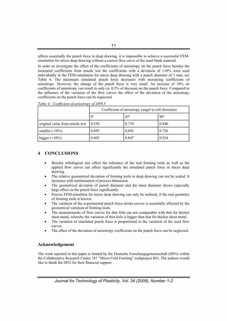
foil thickness of 0.015 mm is obviously larger (with a factor of ca. 4) than that for foil thickness of 0.2 mm. Applying the lowest and the highest flow curves respectively into the FEM-simulaiton the simulated punch force-stroke-curves show then the variation of the punch force, which is caused by and also proportional to the variation of the flow curves, see Fig. 12. Due to the very small thickness of the thin foils the drawing force in the tensile test is very small and thus very difficult for the measurement. Therefore the larger variation of thin foils might be cause by the measurement in tensile tests as well as by the material properties.
Fig. 11 - Variation of flow curves of Al99.5 for thicknesses of s0=0.2 mm and s0=0.015 mm
Fig. 12 - Effect of the variation of the flow curves on the punch force
Besides the variations the other features of the flow curves of Al99.5 in these two thicknesses differ from each other too. For the thickness of s0=0.015 mm the uniform elongation is less than 5%, while for the thickness of s0=0.2 mm it is more than 20%. The yield stress and the tensile strength for the thickness of s0=0.015 mm are about 45 MPa and 84 MPa respectively, while for the thickness of s0=0.2 mm they are about 30 MPa and 74 MPa respectively. Since the flow stress
11
Journal for Technology of Plasticity, Vol. 34 (2009), Number 1-2
affects essentially the punch force in deep drawing, it is impossible to achieve a successful FEM-simulation for micro deep drawing without a correct flow curve of the used blank material.
In order to investigate the effect of the coefficients of anisotropy on the punch force besides the measured coefficients from tensile test the coefficients with a deviation of 10% were used individually in the FEM-simulation for micro deep drawing with a punch diameter of 1 mm, see Table 4. The maximum simulated punch force decreases with increasing coefficients of anisotropy. However, the change of the punch force is very small. An increase of 10% on coefficients of anisotropy can result in only ca. 0.5% of decrease on the punch force. Compared to the influence of the variation of the flow curves the effect of the deviation of the anisotropy coefficients on the punch force can be neglected.
Table 4: Coefficient of anisotropy of Al99.5
Coefficient of anisotropy (angel to roll direction)
0o 45o 90o
original value from tensile test 0.550 0.770 0.840
smaller (-10%) 0.495 0.693 0.756
bigger (+10%) 0.605 0.847 0.924
4 CONCLUSIONS
Besides tribological size effect the tolerance of the real forming tools as well as the applied flow curves can affect significantly the simulated punch force in micro deep drawing.
The relative geometrical deviation of forming tools in deep drawing can not be scaled. It increases with minimisation of process dimension.
The geometrical deviation of punch diameter and die inner diameter shows especially large effect on the punch force significantly.
Precise FEM-simultion for micro deep drawing can only be realised, if the real geometry of forming tools is known.
The variation of the experimental punch force-stroke-curves is essentially affected by the geometrical variation of forming tools.
The measurements of flow curves for thin foils are not comparable with that for thicker sheet metal, whereby the variation of thin foils is bigger than that for thicker sheet metal.
The variation of simulated punch force is proportional to the variation of the used flow curves.
The effect of the deviation of anisotropy coefficients on the punch force can be neglected.
Acknowledgement
The work reported in this paper is funded by the Deutsche Forschungsgemeinschaft (DFG) within the Collaborative Research Centre 747 “Micro Cold Forming” (subproject B3). The authors would like to thank the DFG for their financial support.
12
Journal for Technology of Plasticity, Vol. 34 (2009), Number 1-2
The tensile tests for the Al99.5 in different thicknesses were carried out at the institute of Metal Forming and Casting (UTG) in Munich and the Stiftung Institut fuer Werkstofftechnik (IWT) in Bremen in Germany. The forming tools used in this work were partially measured at BIMAQ in Bremen in Germany. The authors would like to thank them sincerely.
REFERENCES
[1] M. Geiger, M. Kleiner, R. Eckstein, N. Tiesler, U. Engel: Microforming, CIRP Annals, Vol. 50/2 (2001) 445-462.
[2] Wicht, H., Bouchaud, J., Panorama - NEXUS Market Analysis for MEMS and Microsystems III 2005-2009, MST news - International newsletter on micro-nano integration, No. 5/05, 2005, 33-34.
[3] Vollertsen, F., Biermann, D., Hansen, H.N., Jawahir, I.S., Kuzman, K., Size effects in manufacturing of metallic components, Annals of the CIRP, Vol. 58/2 (2009), DOI 10.1016/j.cirp.2009.09.002.
[4] Tiesler, N., Engel, U., Microforming – Effects of Miniaturisation, Proceedings of 8th International Conference on Metal Forming, Eds. Pietrzyk, M., Kusiak, J., ec al., Kraków (2000), 355-360.
[5] Hu, Z., Schulze Niehoff, H., Vollertsen, F., Tribological size effects in deep drawing, ICNFT2007, eds. F. Vollertsen and S. Yuan, BIAS Verlag, Bremen, Germany (2007), 573- 582.
[6] Hu, Z., Analyse des tribologischen Groesseneffekts beim Blechumformen, Dissertation, Strahltechnik Band 37, BIAS-Verlag, 2009, ISBN 978-3-933762-30-6.
[7] Pawelski, O., Aehnlichkeitstheorie in der Umformtechnik. In: Dahl, W.; Kopp, R.; Pawelski, O. (Eds.): Umformtechnik Plastomechanik und Werkstoffkunde, Verlag Stahleisen, Düsseldorf, 1993.
[8] Messner, A., 1998, Kaltmassivumformung Metallischer Kleinstteile –Werkstoffverhalten, Wirkflächeenreibung, Prozessauslegung-, Eds. Geiger, M., Feldmann, K., Meisenbach Verlag Bamberg, 75, ISBN 3-87525-100-8
[9] Hoffmann, H., Hong, S., Tensile test of very thin Sheet Metal and Determination of Flow Stress Considering the Scaling Effect, Annals of the CIRP 2006, Vol. 55/1, 263-266.
[10] Hu, Z., Schulze Niehoff, H., Vollertsen, F., Determination of Friction Function in Deep Drawing with Respect to Size Effects, ICTP2008 (9th International Conference on Technology of Plasticity), eds. D.Y. Yang, Y.H. Kim and C.H. Park, ISBN 978-89-5708-151- 8, Gyeongiu, Korea, 2008, 281-282.
[11] Vollertsen, F., Hu, Z., Determination of Size-Dependent Friction Functions in Sheet Metal Forming with Respect to the Distribution of the Contact Pressure, Production Engineering – Research and Development, (2008) 2: 345-350.
[12] F. Vollertsen, Z. Hu: Tibological Size Effects in Sheet Metal Forming Measured by a Strip Drawing Test, CIRP Annals, Vol. 55/1 (2006) 291 – 294
[13] M.W. Storoschew, E. A. Popow: Grundlagen der Umformtechnik, VEB Verlag Technik Berlin, (1968)
13
Journal for Technology of Plasticity, Vol. 34 (2009), Number 1-2
UPOREĐENJE UTICAJA VARIJACIJE KRIVE TEČENJA I TOLERANCIJE ALATA U PROCESU
MIKRODEFORMISANJA
Zhenyu Hu, Frank Vollertsen
BIAS Bremer Institut fuer angewandte Strahltechnik, Germany
REZIME
U procesu mikro deformisanja varijacija krive sila – put je veća nego što je to u slučaju makro deformisanja. Sila žiga kod dubokog izvlačenja je određena krivom tečenja materijala, koeficijentom trenja i geometrijom procesa. Prva dva uticajna faktora direktno su zavisna od efekta veličine (size effect), a na treći faktor utiču izradne tolerancije alata, što je indirektno takođe povezano sa efektom veličine. U ovom radu je istraživano koliko je osetljiva sila na žigu kod mikro dubokog izvlačenja u odnosu na gore navedene uticajne faktore. Korišćena je metoda konačnih elemenata (MKE). Istraživanje i rezultati koji su dobijeni potvrđuju efikasnost MKE metode u analizi mikro deformisanja. Ključne reči: Mikrodeformisanje, MKE, efekat veličine.