Embed Size (px)
Citation preview

Comparisonofmachineimpedancecalculationwithbeambasedmeasurements
KarlBaneandDeminZhou
Acknowledgements:
T.Abe,K.Akai,Y.Cai,J.Flanagan,H.Fukuma,Y.Funakoshi,T.Kobayashi,T.Ieiri,H.Ikeda,T.Ishibashi,T.Mitsuhashi,Y.Morita,K.Ohmi,K.Oide,K.Shibata,
Y.Suetsugu,M.Tobiyama
InternationalWorkshopon ImpedancesandBeamInstabilitiesinParticleAccelerators
Benevento,Italy,20September,2017
2
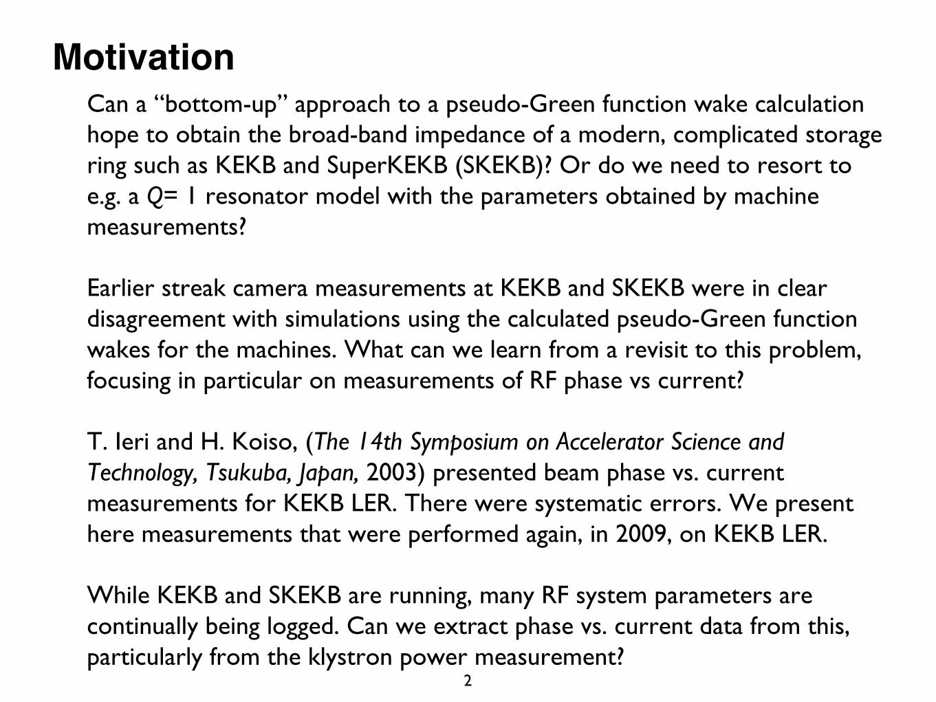
MotivationCan a “bottom-up” approach to a pseudo-Green function wake calculation hope to obtain the broad-band impedance of a modern, complicated storage ring such as KEKB and SuperKEKB (SKEKB)? Or do we need to resort to e.g. a Q= 1 resonator model with the parameters obtained by machine measurements?
Earlier streak camera measurements at KEKB and SKEKB were in clear disagreement with simulations using the calculated pseudo-Green function wakes for the machines. What can we learn from a revisit to this problem, focusing in particular on measurements of RF phase vs current?
T. Ieri and H. Koiso, (The 14th Symposium on Accelerator Science and Technology, Tsukuba, Japan, 2003) presented beam phase vs. current measurements for KEKB LER. There were systematic errors. We present here measurements that were performed again, in 2009, on KEKB LER.
While KEKB and SKEKB are running, many RF system parameters are continually being logged. Can we extract phase vs. current data from this, particularly from the klystron power measurement?
Outline
3
➤ Introduction➤ 3Dwakefieldcomputations➤MWIsimulation➤ Beamphasemeasurement➤ HOMpower➤ Summary
4
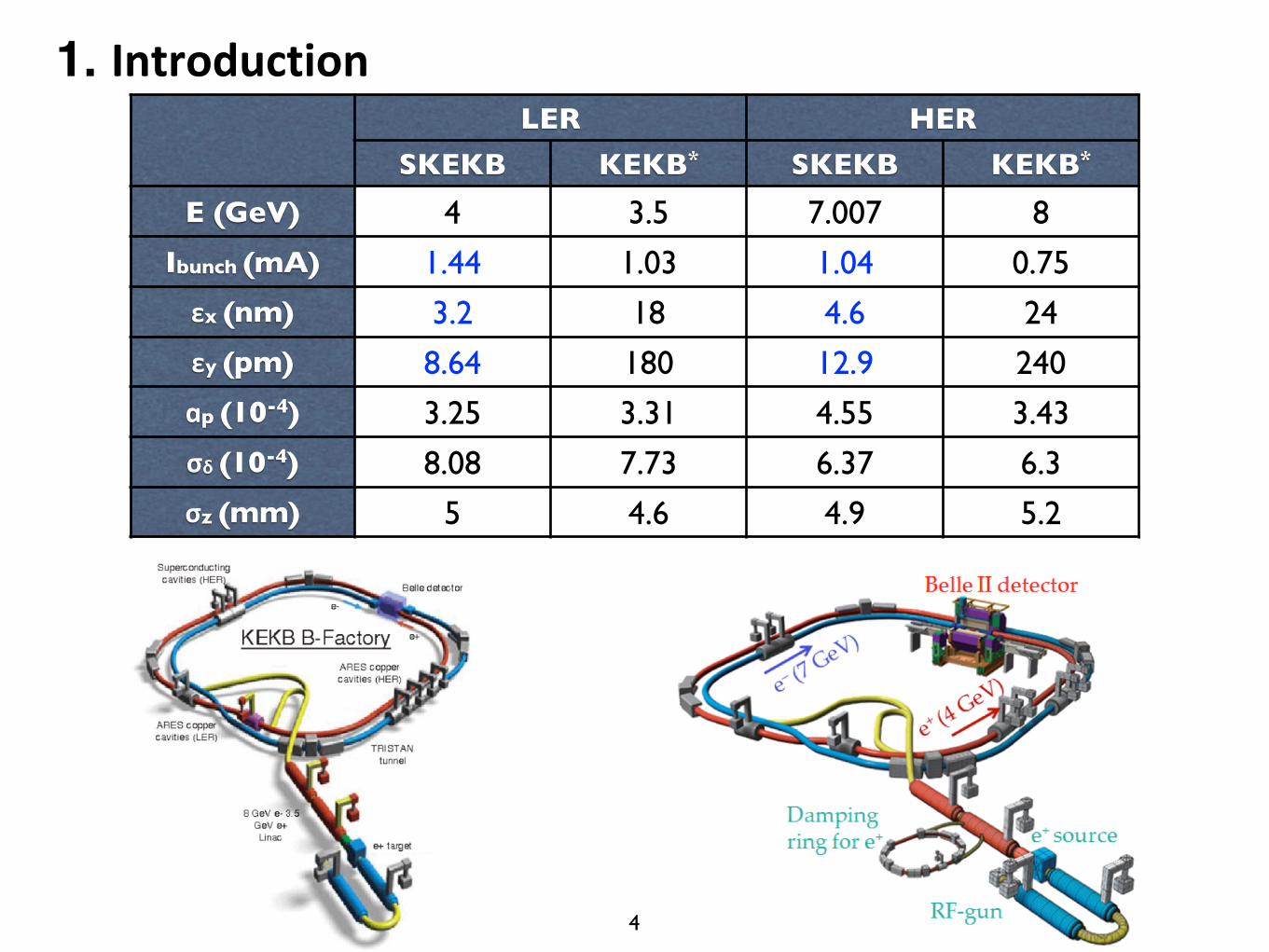
LER HERSKEKB KEKB* SKEKB KEKB*
E (GeV) 4 3.5 7.007 8
Ibunch (mA) 1.44 1.03 1.04 0.75εx (nm) 3.2 18 4.6 24εy (pm) 8.64 180 12.9 240ɑp (10-4) 3.25 3.31 4.55 3.43σδ (10-4) 8.08 7.73 6.37 6.3σz (mm) 5 4.6 4.9 5.2
1. Introduction
5
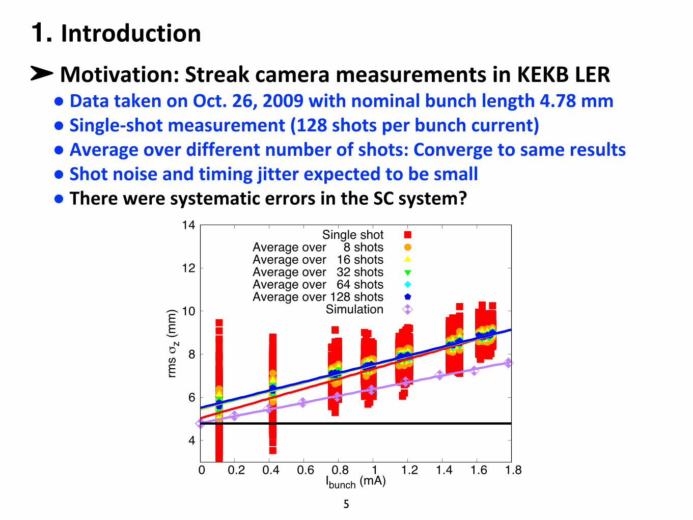
➤Motivation:StreakcamerameasurementsinKEKBLER● DatatakenonOct.26,2009withnominalbunchlength4.78mm● Single-shotmeasurement(128shotsperbunchcurrent)● Averageoverdifferentnumberofshots:Convergetosameresults● Shotnoiseandtimingjitterexpectedtobesmall● ThereweresystematicerrorsintheSCsystem?
1. Introduction
4
6
8
10
12
14
0 0.2 0.4 0.6 0.8 1 1.2 1.4 1.6 1.8
rms σ
z (m
m)
Ibunch (mA)
Single shotAverage over 8 shotsAverage over 16 shotsAverage over 32 shotsAverage over 64 shotsAverage over 128 shots
Simulation
6
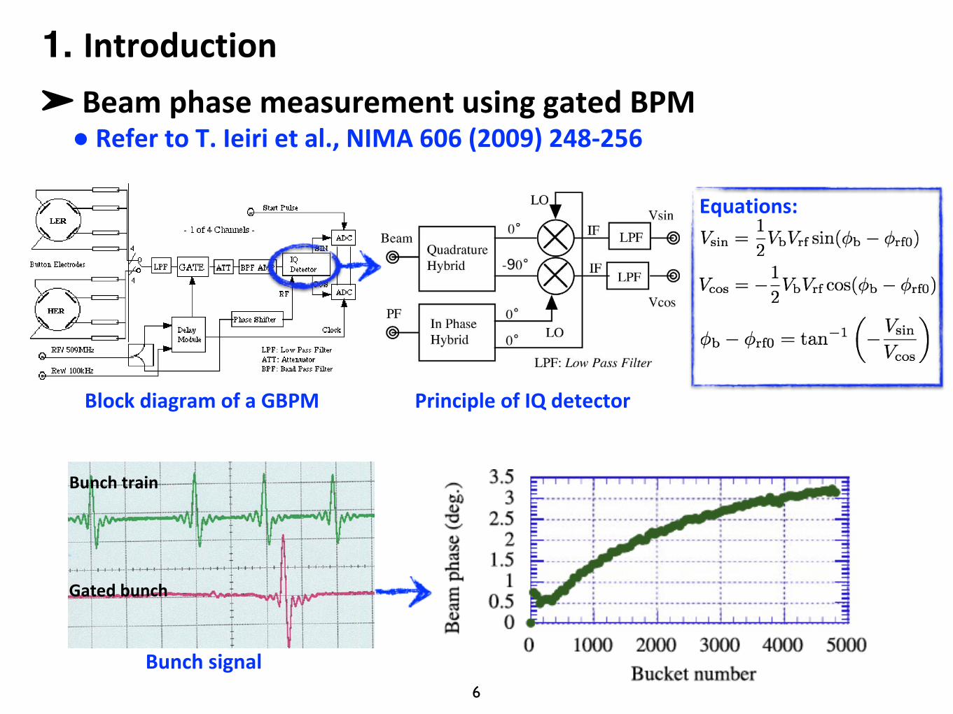
➤ BeamphasemeasurementusinggatedBPM● RefertoT.Ieirietal.,NIMA606(2009)248-256
BlockdiagramofaGBPM
Bunchsignal
Bunchtrain
Gatedbunch
PrincipleofIQdetector
Equations:
1. Introduction
7
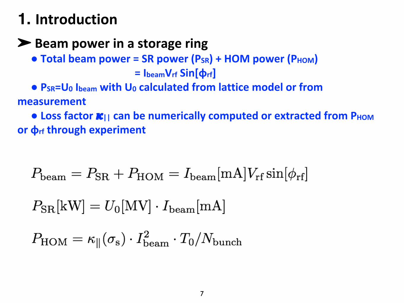
➤ Beampowerinastoragering● Totalbeampower=SRpower(PSR)+HOMpower(PHOM)
=IbeamVrf Sin[ɸrf]● PSR=U0 Ibeam withU0 calculatedfromlatticemodelorfrom
measurement● Lossfactor𝜿|| canbenumericallycomputedorextractedfromPHOM
orɸrf throughexperiment
1. Introduction
8
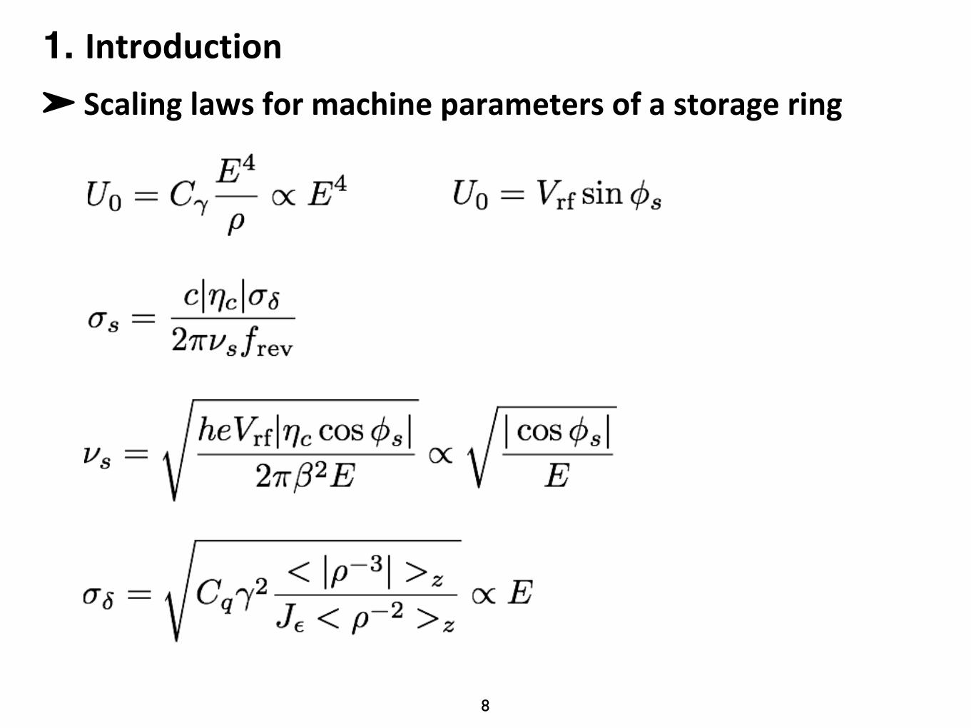
➤ Scalinglawsformachineparametersofastoragering
1. Introduction
9
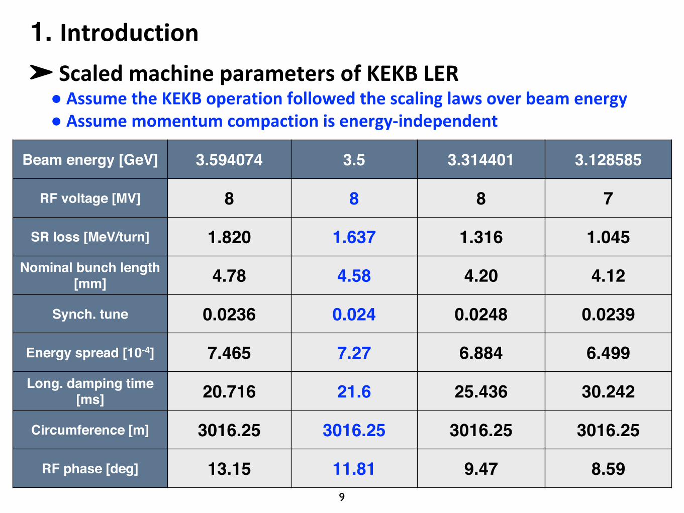
➤ ScaledmachineparametersofKEKBLER● AssumetheKEKBoperationfollowedthescalinglawsoverbeamenergy● Assumemomentumcompactionisenergy-independent
Beam energy [GeV] 3.594074 3.5 3.314401 3.128585
RF voltage [MV] 8 8 8 7
SR loss [MeV/turn] 1.820 1.637 1.316 1.045Nominal bunch length
[mm] 4.78 4.58 4.20 4.12
Synch. tune 0.0236 0.024 0.0248 0.0239
Energy spread [10-4] 7.465 7.27 6.884 6.499Long. damping time
[ms] 20.716 21.6 25.436 30.242
Circumference [m] 3016.25 3016.25 3016.25 3016.25
RF phase [deg] 13.15 11.81 9.47 8.59
1. Introduction
10
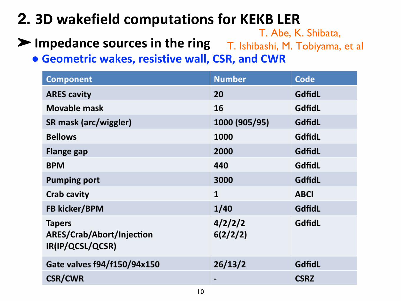
➤ Impedancesourcesinthering● Geometricwakes,resistivewall,CSR,andCWR
2. 3DwakefieldcomputationsforKEKBLERT. Abe, K. Shibata,
T. Ishibashi, M. Tobiyama, et al
11
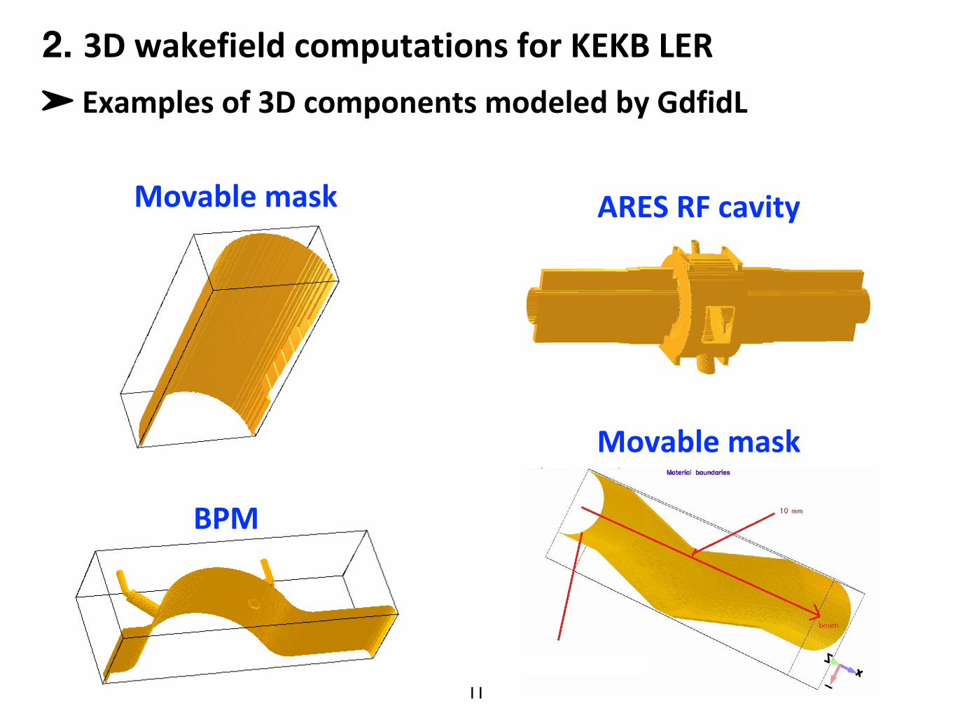
➤ Examplesof3DcomponentsmodeledbyGdfidL
2. 3DwakefieldcomputationsforKEKBLER
ARESRFcavity
BPM
Movablemask
Movablemask
12
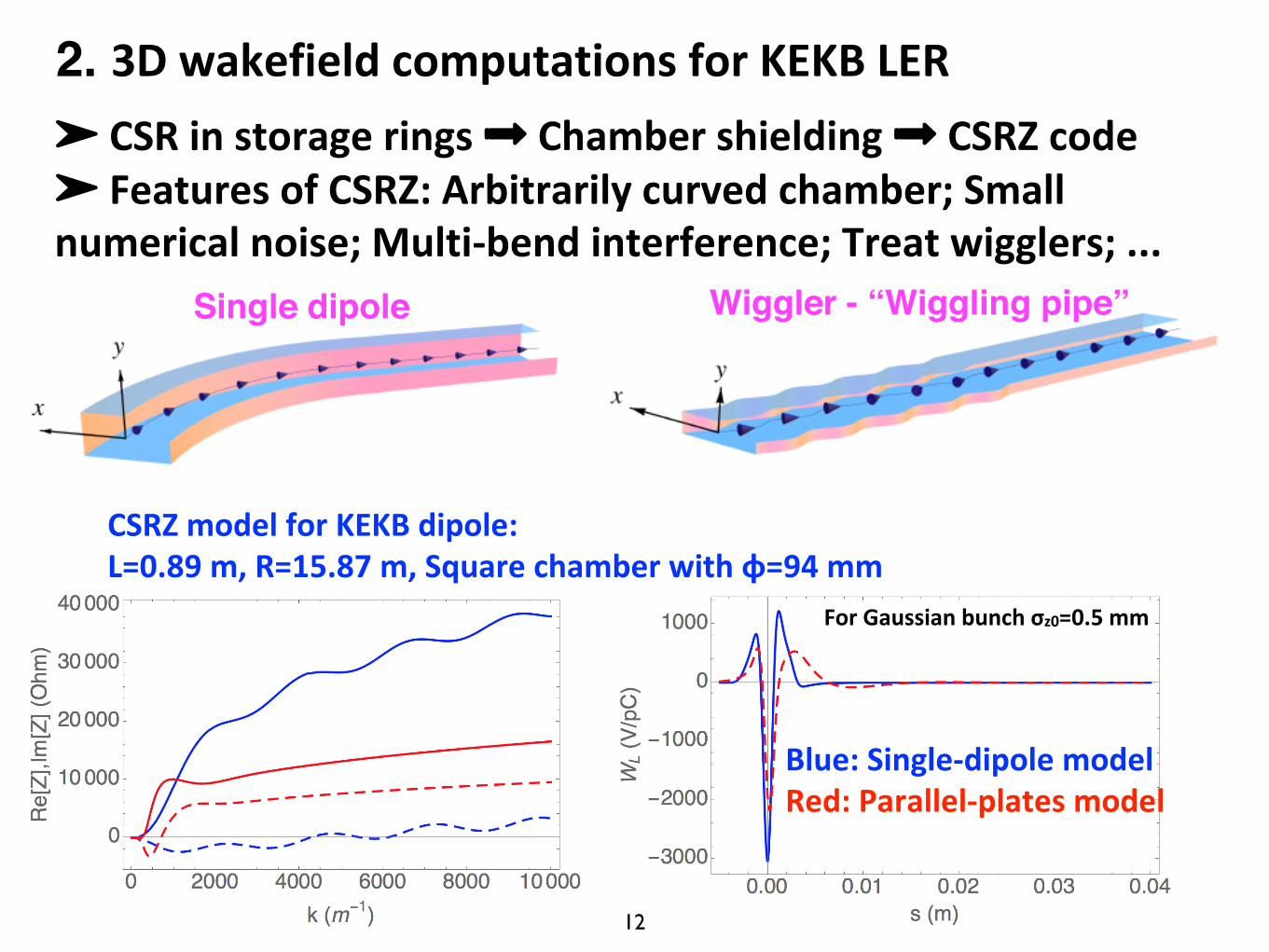
➤ CSRinstoragerings➟ Chambershielding➟ CSRZ code➤ FeaturesofCSRZ:Arbitrarilycurvedchamber;Smallnumericalnoise;Multi-bendinterference;Treatwigglers;...
2. 3DwakefieldcomputationsforKEKBLER
Wiggler - “Wiggling pipe”Single dipole
CSRZmodelforKEKBdipole:L=0.89m,R=15.87m,Squarechamberwithɸ=94mm
Blue:Single-dipolemodelRed:Parallel-platesmodel
ForGaussianbunchσz0=0.5mm
13
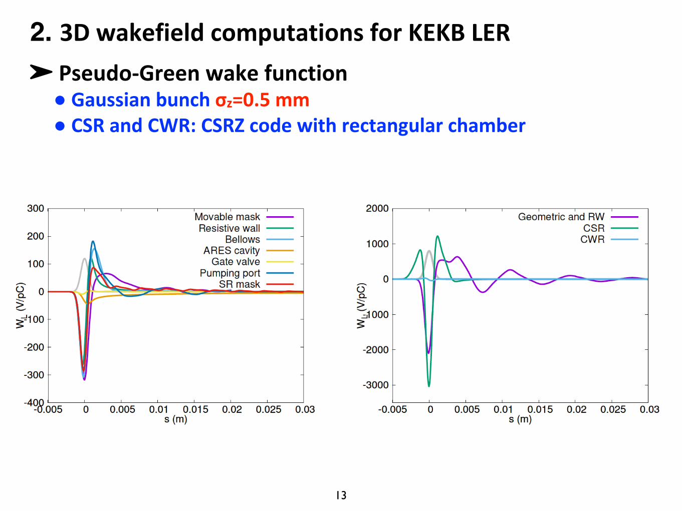
➤ Pseudo-Greenwakefunction● Gaussianbunchσz=0.5mm● CSRandCWR:CSRZcodewithrectangularchamber
2. 3DwakefieldcomputationsforKEKBLER
14
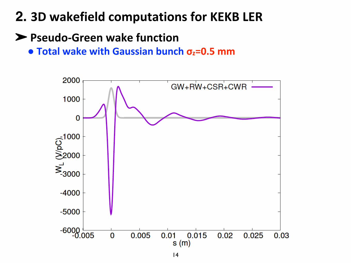
➤ Pseudo-Greenwakefunction● TotalwakewithGaussianbunchσz=0.5mm
2. 3DwakefieldcomputationsforKEKBLER
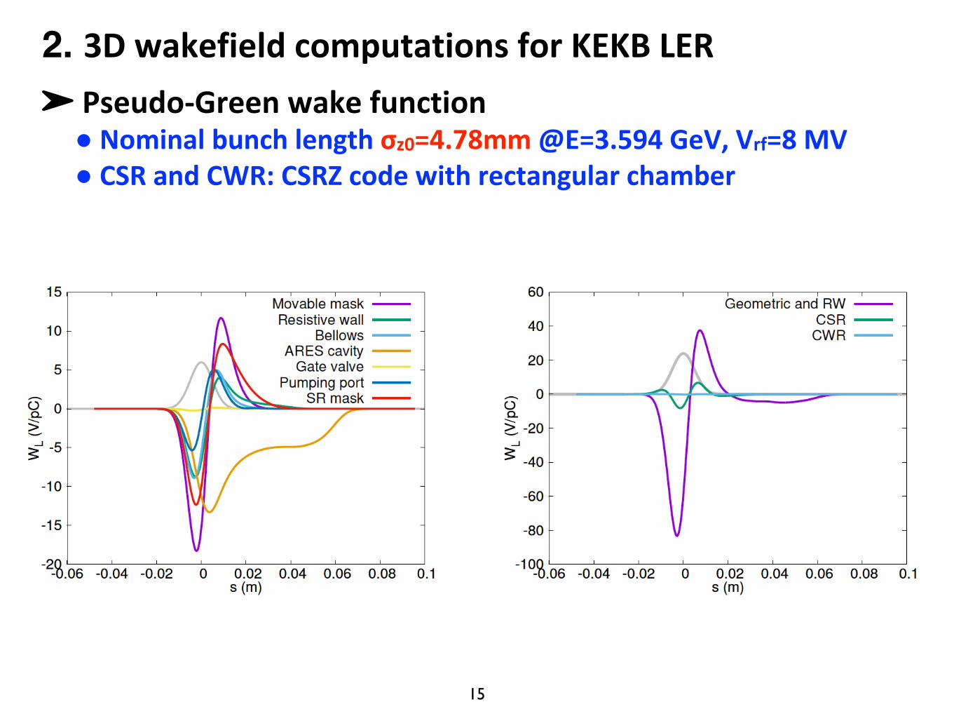
15
➤ Pseudo-Greenwakefunction● Nominalbunchlengthσz0=4.78mm@E=3.594GeV,Vrf=8MV● CSRandCWR:CSRZcodewithrectangularchamber
2. 3DwakefieldcomputationsforKEKBLER
16
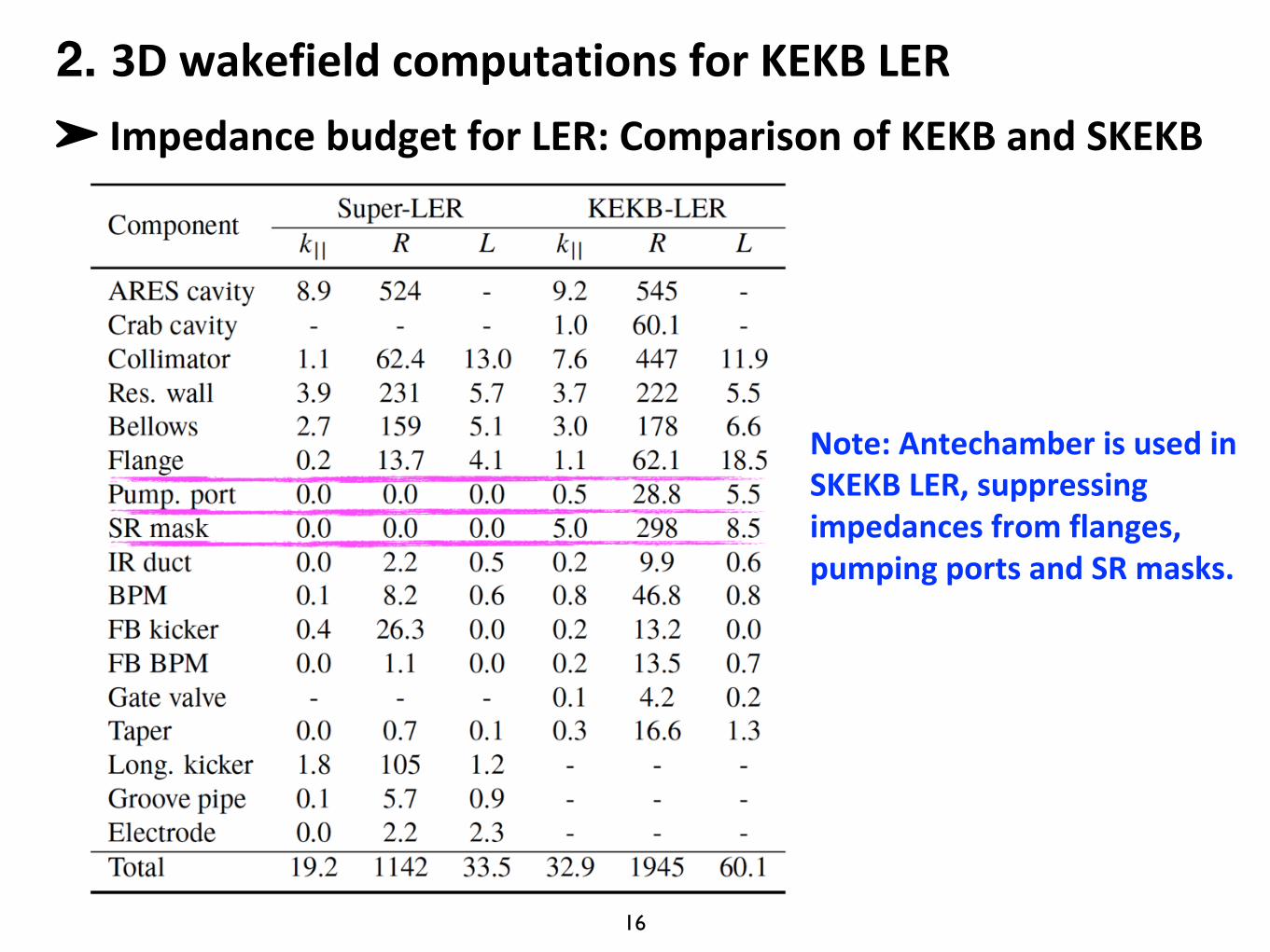
➤ ImpedancebudgetforLER:ComparisonofKEKBandSKEKB
2. 3DwakefieldcomputationsforKEKBLER
Note:AntechamberisusedinSKEKBLER,suppressingimpedancesfromflanges,pumpingportsandSRmasks.
17
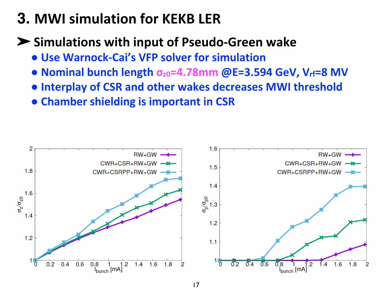
➤ SimulationswithinputofPseudo-Greenwake● UseWarnock-Cai’sVFPsolver forsimulation● Nominalbunchlengthσz0=4.78mm@E=3.594GeV,Vrf=8MV● InterplayofCSRandotherwakesdecreasesMWIthreshold● Chamber shieldingis importantinCSR
3. MWIsimulationforKEKBLER
18
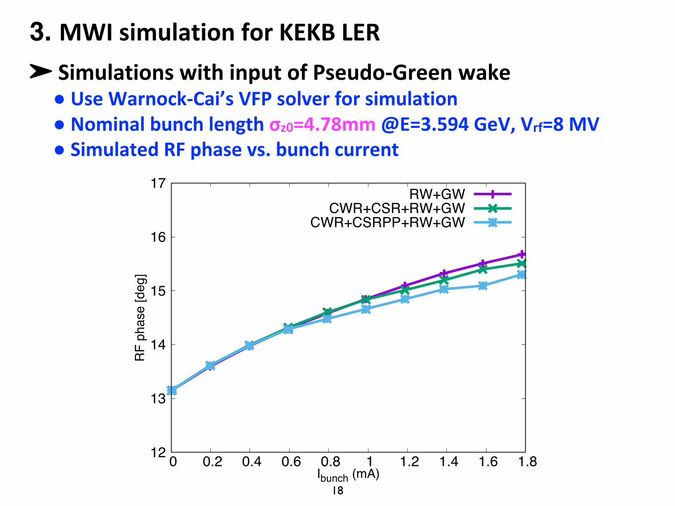
➤ SimulationswithinputofPseudo-Greenwake● UseWarnock-Cai’sVFPsolver forsimulation● Nominalbunchlengthσz0=4.78mm@E=3.594GeV,Vrf=8MV● SimulatedRFphasevs.bunchcurrent
3. MWIsimulationforKEKBLER
12
13
14
15
16
17
0 0.2 0.4 0.6 0.8 1 1.2 1.4 1.6 1.8
RF
phas
e [d
eg]
Ibunch (mA)
RW+GWCWR+CSR+RW+GW
CWR+CSRPP+RW+GW
19
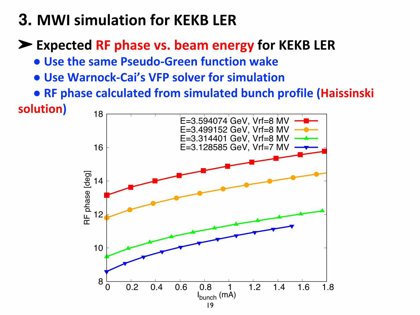
➤ ExpectedRFphasevs.beamenergy forKEKBLER● UsethesamePseudo-Greenfunctionwake● UseWarnock-Cai’sVFPsolverforsimulation● RFphasecalculatedfromsimulatedbunchprofile(Haissinski
solution)
3. MWIsimulationforKEKBLER
8
10
12
14
16
18
0 0.2 0.4 0.6 0.8 1 1.2 1.4 1.6 1.8
RF
phas
e [d
eg]
Ibunch (mA)
E=3.594074 GeV, Vrf=8 MVE=3.499152 GeV, Vrf=8 MVE=3.314401 GeV, Vrf=8 MVE=3.128585 GeV, Vrf=7 MV
20
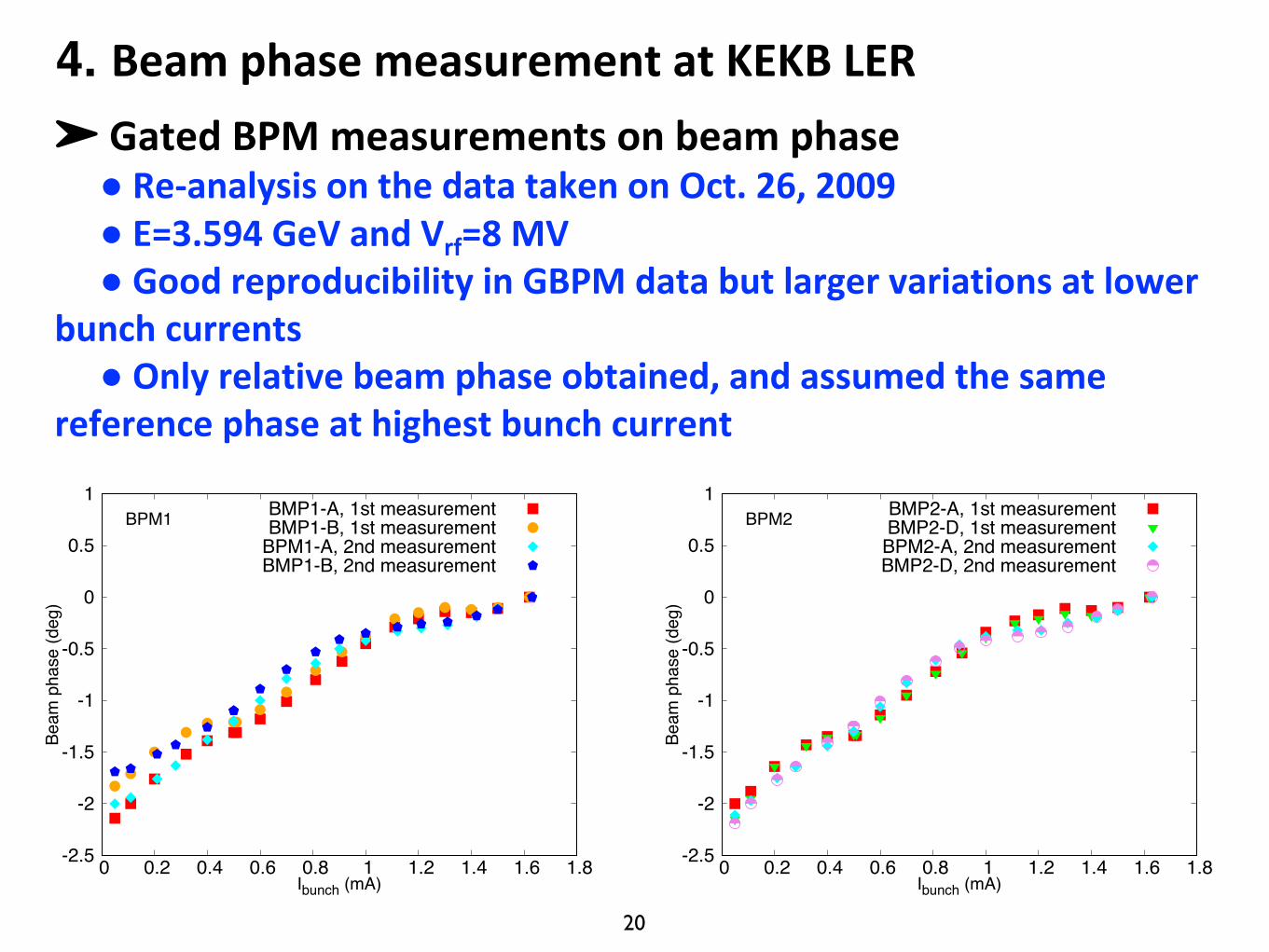
➤ GatedBPMmeasurementsonbeamphase● Re-analysisonthedatatakenonOct.26,2009● E=3.594GeVandVrf=8MV● GoodreproducibilityinGBPMdatabutlargervariationsatlower
bunchcurrents● Only relativebeamphase obtained,and assumed the same
reference phase athighest bunch current
4. BeamphasemeasurementatKEKBLER
-2.5
-2
-1.5
-1
-0.5
0
0.5
1
0 0.2 0.4 0.6 0.8 1 1.2 1.4 1.6 1.8
BPM1
Beam
pha
se (d
eg)
Ibunch (mA)
BMP1-A, 1st measurementBMP1-B, 1st measurement
BPM1-A, 2nd measurementBMP1-B, 2nd measurement
-2.5
-2
-1.5
-1
-0.5
0
0.5
1
0 0.2 0.4 0.6 0.8 1 1.2 1.4 1.6 1.8
BPM2
Beam
pha
se (d
eg)
Ibunch (mA)
BMP2-A, 1st measurementBMP2-D, 1st measurement
BPM2-A, 2nd measurementBMP2-D, 2nd measurement
21
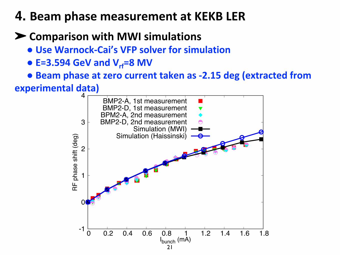
➤ ComparisonwithMWIsimulations● UseWarnock-Cai’sVFPsolverforsimulation● E=3.594GeVandVrf=8MV● Beamphaseatzerocurrenttakenas-2.15deg(extractedfrom
experimentaldata)
4. BeamphasemeasurementatKEKBLER
-1
0
1
2
3
4
0 0.2 0.4 0.6 0.8 1 1.2 1.4 1.6 1.8
RF
phas
e sh
ift (d
eg)
Ibunch (mA)
BMP2-A, 1st measurementBMP2-D, 1st measurement
BPM2-A, 2nd measurementBMP2-D, 2nd measurement
Simulation (MWI)Simulation (Haissinski)
22
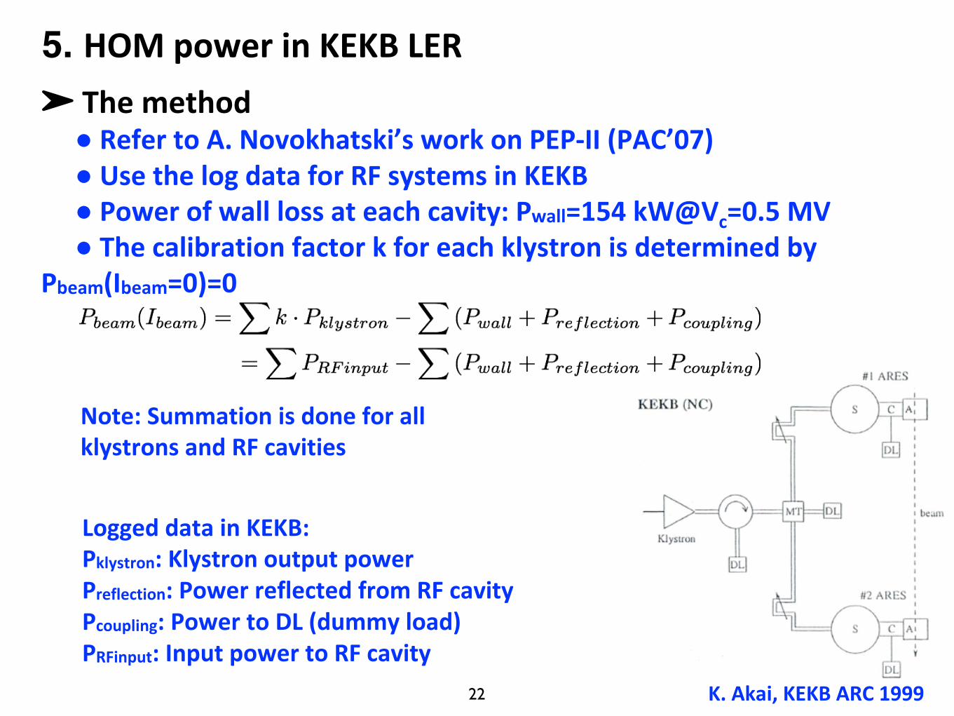
➤ Themethod● RefertoA.Novokhatski’sworkonPEP-II(PAC’07)● UsethelogdataforRFsystemsinKEKB● Powerofwalllossateachcavity:Pwall=154kW@Vc=0.5MV● Thecalibrationfactorkforeachklystronisdeterminedby
Pbeam(Ibeam=0)=0
K.Akai,KEKBARC1999
Loggeddata inKEKB:Pklystron:KlystronoutputpowerPreflection:PowerreflectedfromRFcavityPcoupling:PowertoDL(dummyload)PRFinput:InputpowertoRFcavity
Note:SummationisdoneforallklystronsandRFcavities
5. HOMpowerinKEKBLER
23
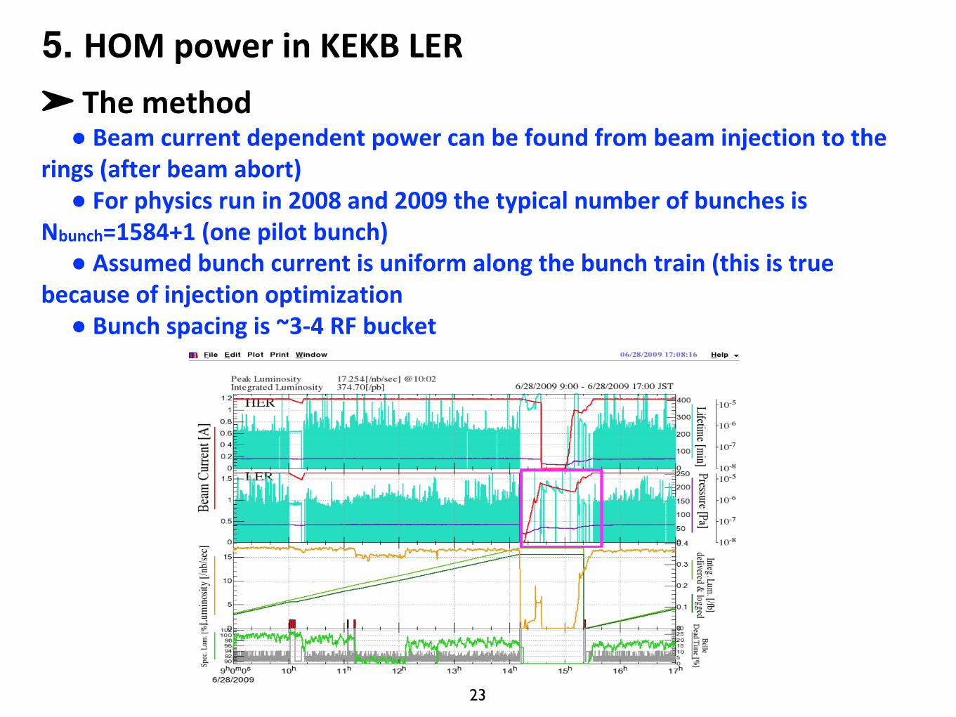
➤ Themethod● Beamcurrentdependentpowercanbefoundfrombeaminjectiontothe
rings(afterbeamabort)● Forphysicsrunin2008and2009thetypicalnumberofbunchesis
Nbunch=1584+1(onepilotbunch)● Assumed bunchcurrentisuniformalongthebunchtrain(thisistrue
becauseofinjectionoptimization● Bunchspacingis~3-4RFbucket
5. HOMpowerinKEKBLER
24
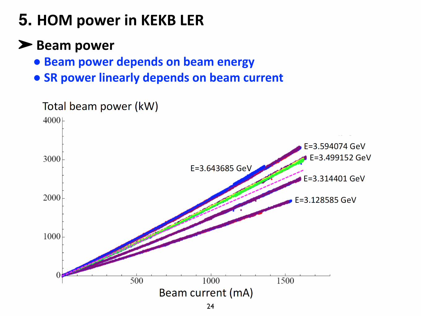
➤ Beampower● Beampowerdependsonbeamenergy● SRpowerlinearlydependsonbeamcurrent
5. HOMpowerinKEKBLER
25
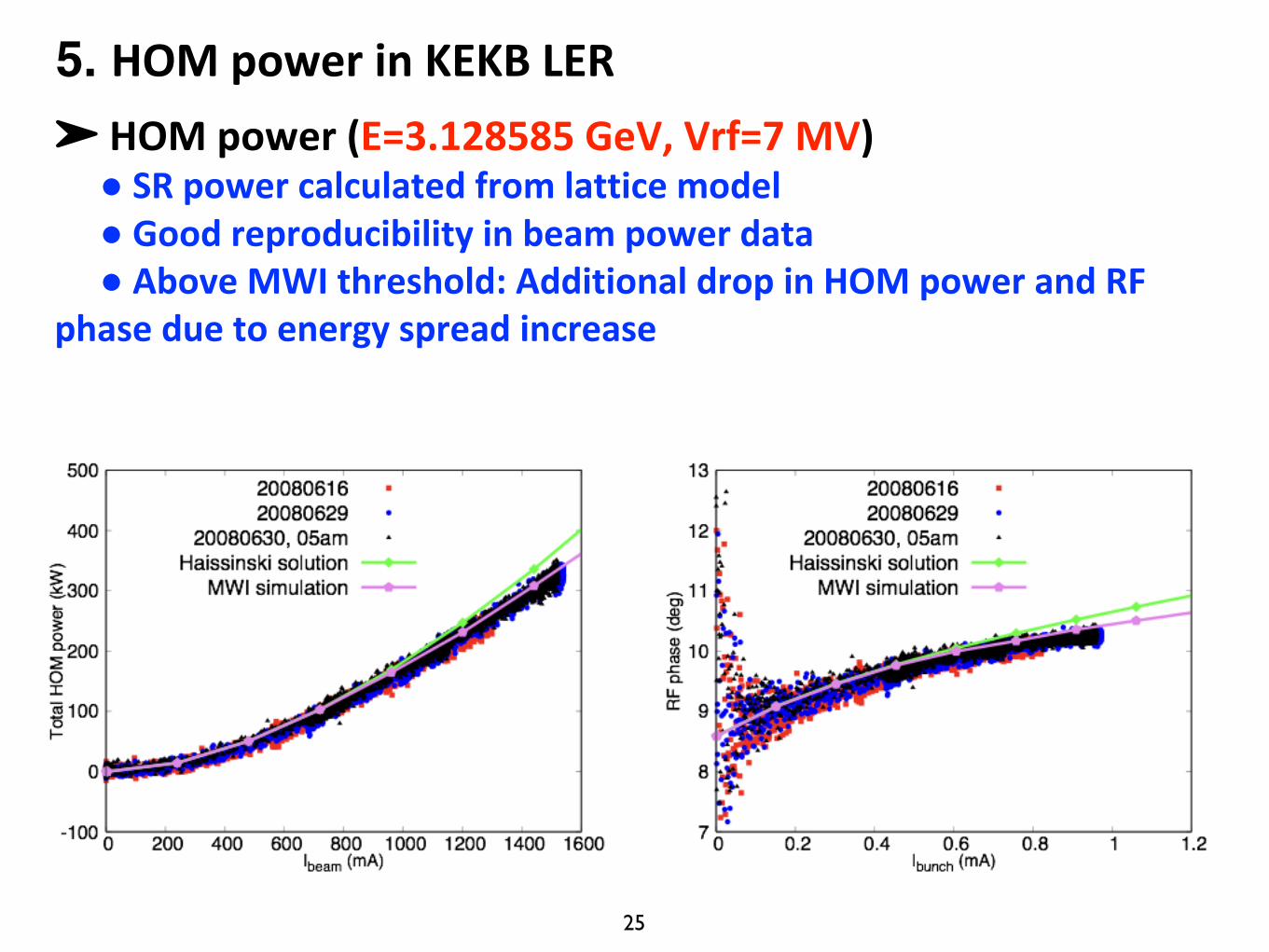
➤ HOMpower(E=3.128585GeV,Vrf=7MV)● SRpowercalculatedfromlatticemodel● Goodreproducibilityin beampowerdata● AboveMWIthreshold:AdditionaldropinHOMpowerandRF
phase duetoenergyspreadincrease
5. HOMpowerinKEKBLER
26
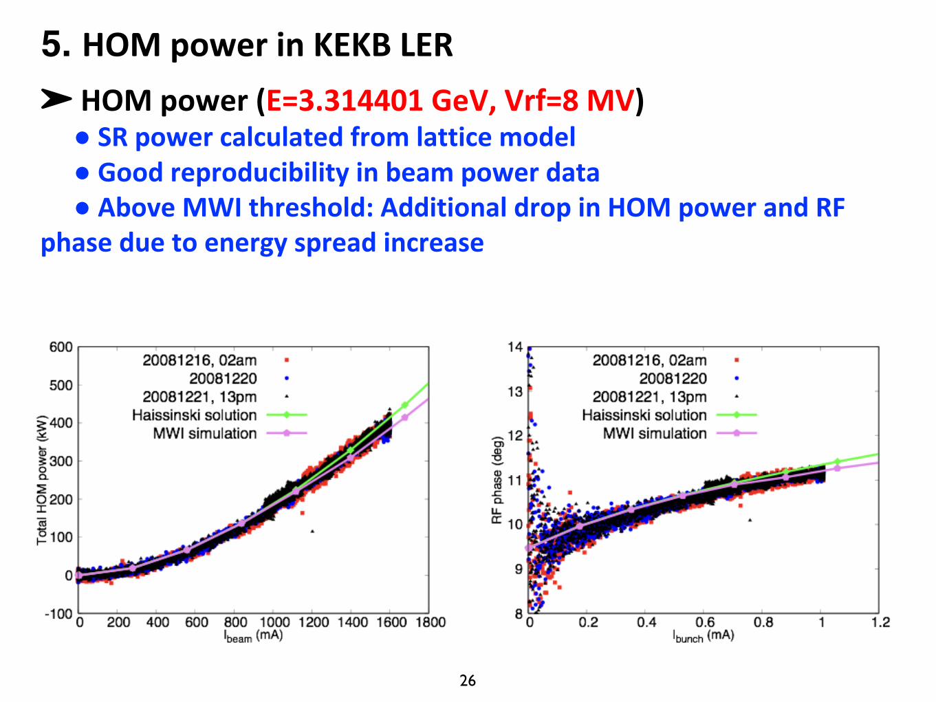
➤ HOMpower(E=3.314401GeV,Vrf=8MV)● SRpowercalculatedfromlatticemodel● Goodreproducibilityinbeampowerdata● AboveMWIthreshold:AdditionaldropinHOMpowerandRF
phaseduetoenergyspreadincrease
5. HOMpowerinKEKBLER
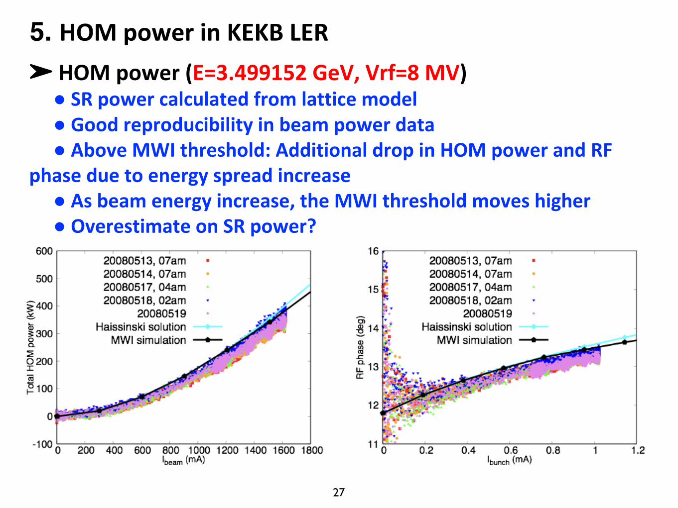
27
➤ HOMpower(E=3.499152GeV,Vrf=8MV)● SRpowercalculatedfromlatticemodel● Goodreproducibilityinbeampowerdata● AboveMWIthreshold:AdditionaldropinHOMpowerandRF
phaseduetoenergyspreadincrease● Asbeamenergyincrease,theMWIthresholdmoveshigher● OverestimateonSRpower?
5. HOMpowerinKEKBLER
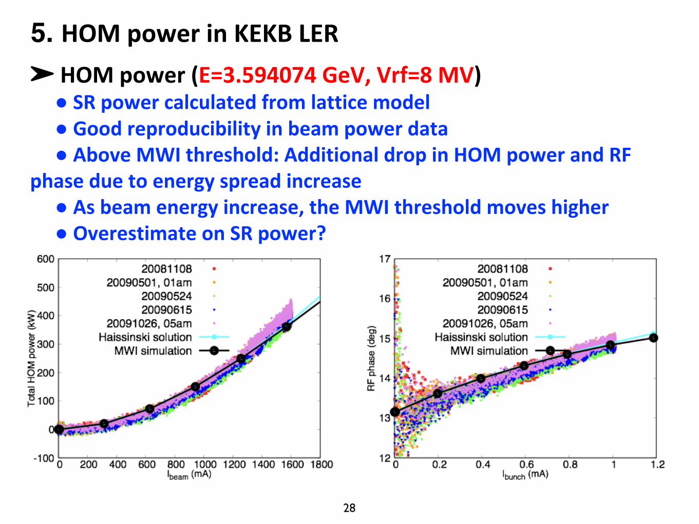
28
➤ HOMpower(E=3.594074GeV,Vrf=8MV)● SRpowercalculatedfromlatticemodel● Goodreproducibilityinbeampowerdata● AboveMWIthreshold:AdditionaldropinHOMpowerandRF
phaseduetoenergyspreadincrease● Asbeamenergyincrease,theMWIthresholdmoveshigher● OverestimateonSRpower?
5. HOMpowerinKEKBLER
29
ConclusionWe have shown that for KEKB LER, beam phase vs I measurements of 2009 agree well with theoretical calculations
From klystron power measurements, we find good agreement to the phase measurements and the calculations, except at high beam energies—the reason is not presently understood. We believe at the moment that this is a problem of us not completely understanding the rf feedback system
The theoretical calculations were "bottom-up” wake calculations, where we numerically obtain the wakes for a short Gaussian bunch for the different vacuum chamber objects in the ring beginning with the chamber drawings, and including CSR. There are no fitting parameters.
CSR is a significant contributor to the pseudo-Green function, with the beam pipe shape being important—the parallel plate model yields a different threshold and bunch length variation with current, and the difference in the phase vs I curve is also significant.
30
The fact that there is good agreement between the phase calculations and measurements suggests that the ring broad-band impedance is well understood. This in spite of the complicated 3D nature of many objects
The calculated KEKB LER ring impedance is resistive in character, which is also indicated by the relative large slope in phase vs I measurements. These results disagree with earlier streak camera measurements that indicated a very inductive impedance (large bunch lengthening and small phase shift with I). We suspect that there were systematic errors in the streak camera measurements. We will try to resolve this discrepancy—which also exists for measurements on the (similar) SuperKEKB rings—once SuperKEKBrestarts next year
31
Backup slides
32
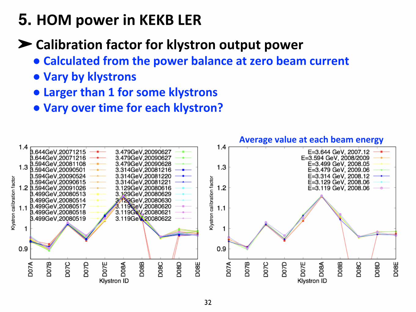
➤ Calibrationfactorforklystronoutputpower● Calculatedfromthepowerbalanceatzerobeamcurrent● Vary byklystrons● Largerthan1forsomeklystrons● Varyovertimeforeachklystron?
Averagevalueateachbeamenergy
5. HOMpowerinKEKBLER
33
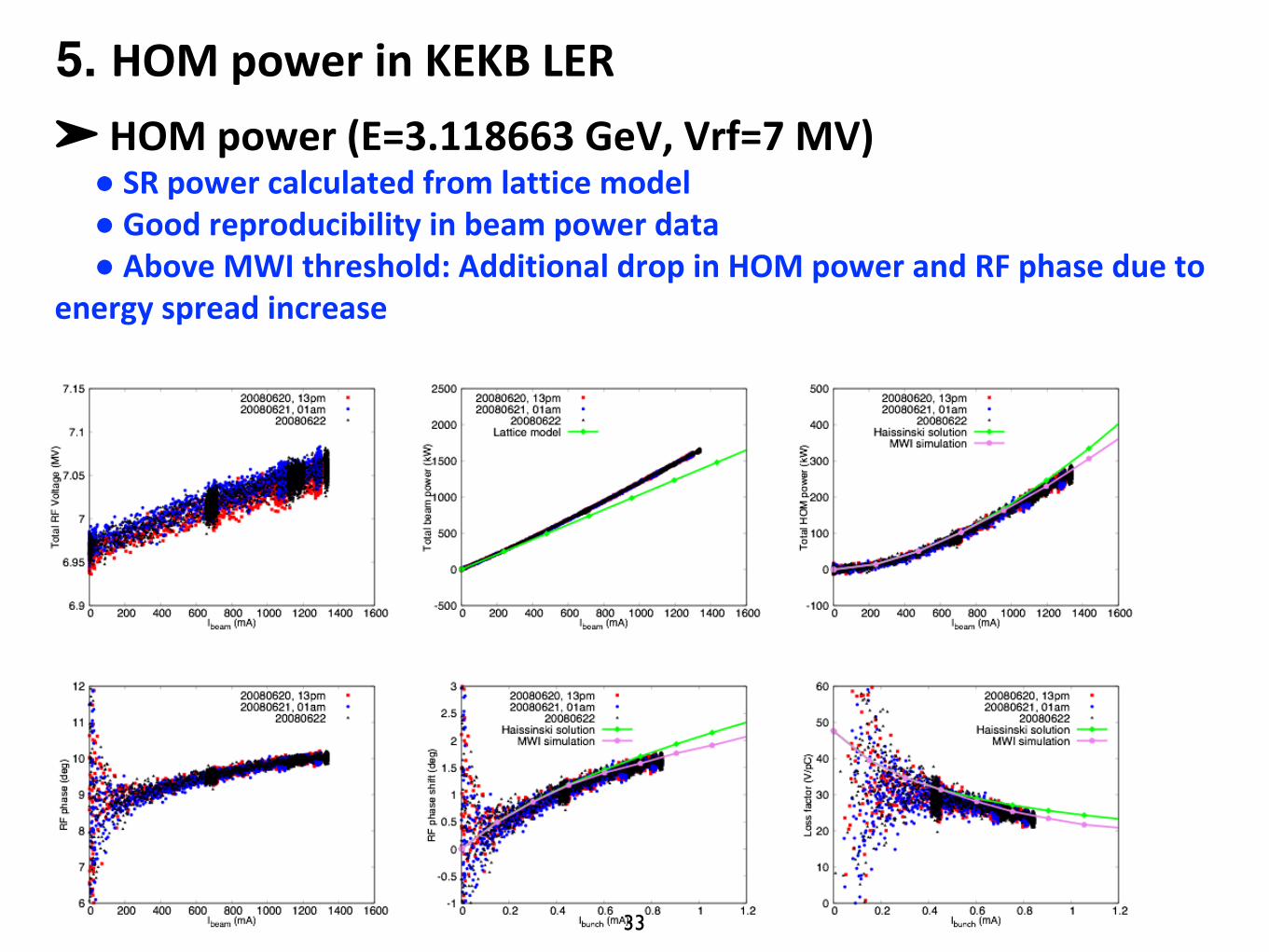
➤ HOMpower(E=3.118663GeV,Vrf=7MV)● SRpowercalculatedfromlatticemodel● Goodreproducibilityinbeampowerdata● AboveMWIthreshold:AdditionaldropinHOMpowerandRFphasedueto
energyspreadincrease
5. HOMpowerinKEKBLER
34
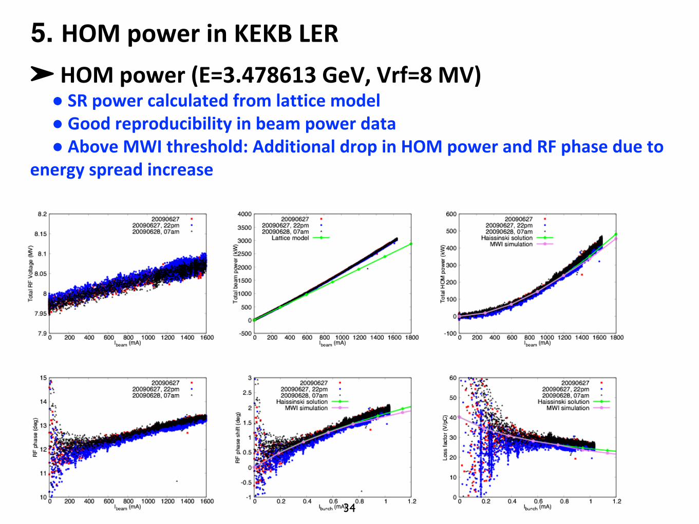
➤ HOMpower(E=3.478613GeV,Vrf=8MV)● SRpowercalculatedfromlatticemodel● Goodreproducibilityinbeampowerdata● AboveMWIthreshold:AdditionaldropinHOMpowerandRFphasedueto
energyspreadincrease
5. HOMpowerinKEKBLER