Embed Size (px)
Citation preview
Materials
www.elsevier.com/locate/matdes
Materials and Design 27 (2006) 1139–1147
& Design
Short communication
Comparison of experimental results obtained by designeddynamometer to fuzzy model for predicting cutting forces in turning
Suleyman Yaldiz, Faruk Unsacar *, Haci Saglam
Selcuk University, Technical Science College, Kampus, 42031 Konya, Turkey
Received 9 November 2004; accepted 10 March 2005Available online 23 May 2005
Abstract
This paper presents a comparison of experimental results and consistent fuzzy rule-based model for estimating the cutting forcesin turning. A dynamometer that can measure static and dynamic cutting forces by using strain gauge and piezo-electric accelerom-eter, respectively, was used for measuring the forces. AISI 1040 steel was used as the workpiece material. Feed force, thrust force andmain cutting force were measured for three combinations of cutting speeds, feedrates and depth of cuts. The rake angle andapproach angle of the cutting tool were kept constant throughout the experiments. The fuzzy model consists of 27 rules. In thisresearch, a Mamdani max–min inference for inference mechanism and the centre of gravity (Centroid) defuzzifier formula methodfor defuzzification were used as these operators assure a linear interpolation of the output between the rules. It has a wide range ofapplications over many types of steels and turning conditions. It is also simple to implement, from a rule-chart mode to an intelligenton-line adaptive control mode. Experimental results were compared with the predicted fuzzy model. The difference between exper-imental and predicted results was obtained as around 99.6%.� 2005 Elsevier Ltd. All rights reserved.
Keywords: C-Dynamometer testing; C-Cutting force prediction; H-Fuzzy modelling
1. Introduction
A considerable amount of investigations has been di-rected towards the prediction and measurement of cut-ting forces. That is because the cutting forcesgenerated during metal cutting have a direct influenceon the generation of heat, and thus tool wear, qualityof machined surface and accuracy of the workpiece.
The importance of monitoring the cutting force inturning has been well recognized in machine tool com-munities. In particular, Sukvittayawong and Inasaki[1], Tlusty and Andrews [2] and Weck [3] pointed outthat on-line and real-time information of the normalcutting force is closely related to the tool wear predic-
0261-3069/$ - see front matter � 2005 Elsevier Ltd. All rights reserved.doi:10.1016/j.matdes.2005.03.010
* Corresponding author. Tel.: +90 332 223 23 52; fax: +90 332 24101 85.
E-mail address: [email protected] (F. Unsacar).
tion, breakage detection or other malfunctioninspections.
Although the cutting force signal can be measured di-rectly by a tool force dynamometer, its use is limited byhigh cost, sensor reliability in the harsh cutting environ-ment, layout constraints (space, weight, etc.) and inter-ference with cutting performance (stiffness reduction).In addition, for a lathe with a turret, a separate dyna-mometer is required for each tool. Some of these limita-tions have been overcome by competing technologiessuch as load inserts, and in some cases, lathes have beencustom designed to accommodate a dynamometer insidethe lathe spindle [3]. However, many of the above limi-tations remain and, therefore, measuring the cuttingforce using a dynamometer and related technologiescontinues to be not fully satisfactory.
Balazinski and Jemielniak [4] introduced a fuzzy deci-sion support system (FDSS) for the estimation of the
F
F
F
F
f
t
c
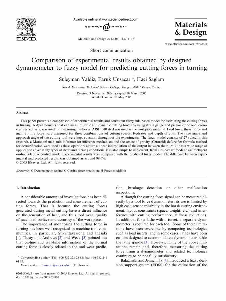
Fig. 1. Cutting force components which occurs during metal cutting inturning.
1140 S. Yaldiz et al. / Materials and Design 27 (2006) 1139–1147
depth of cut and the flank wear during the turning pro-cess. This assessment is based on the feed and the valuesof two cutting force components (cutting force and feedforce).
Balazinski et al. described an application of threeartificial intelligence (AI) methods to estimate tool wearin lathe turning. They compared the use of three AImethods: feed forward–back propagation (FF–BP) neu-ral network (FFBPNN), a fuzzy decision support system(FDSS) and an artificial neural network-based fuzzyinference system (ANNBFIS). The focus was not onlyon the accuracy of the tool-wear prediction but alsoon practical usability of the presented methods [5].
The effectiveness of current monitoring was evaluatedas a measure of the feed cutting force on the feed drivesystem by Li et al. [6]. A monitoring model using anadaptive neuro-fuzzy network was developed and exper-imentally verified on a CNC turning centre.
Recently, Haber et al. [7] developed an indirect cut-ting force controller using fuzzy techniques and an a.c.transformer current sensor located in the spindle motorthat provides the cutting force signals for the end millingprocess.
Chang et al. [8] proposed a neural network to con-struct a model of the spindle cutting system and esti-mated the cutting force and detected the chatter ofCNC machine tools by measuring the voltage and thecurrent of the spindle motor.
The major aim of this study is to develop a fuzzymodel for predicting cutting forces and then evaluateits prediction ability with measured cutting forces.
2. Cutting forces
The cutting forces generated in metal cutting have adirect influence on generation heat, tool wear or failure,quality of machined surface and accuracy of the work-piece. The three components of cutting force which oc-curs during metal cutting in turning are shown in Fig.1. Feed force is represented by Ff, thrust force is repre-sented by Ft and main cutting force is represented by Fc.
Cutting force is one of important characteristic vari-ables to be monitored in the cutting processes. The re-search results show that tool breakage, tool wear, andworkpiece deflection are strongly related to cutting force[2,3].
A cutting force dynamometer designed and manufac-tured by Yaldız and Bıyık [9] have been used to measurecutting force accurately. Though different types of dyna-mometers are available for different cutting applications,the compliance of machine tools, leading to chatter anddimensional error, and lack of overload protection limittheir application owing to high cost [10].
The control of the cutting force of a lathe is of partic-ular interest when a high surface finish and part
dimensional accuracy are desired [11,12]. Force controlsfor turning and milling can be obtained by adjusting thefeedrate of the cutting tool and thereby the chip thick-ness and force on the cutting tool.
3. Fuzzy modelling
Zadeh�s principle of incompatibility says ‘‘As thecomplexity of a system increases, our ability to makeprecise and yet significant statements about its behav-iour diminishes until a threshold is reached beyondwhich precision and significance (or relevance) becomealmost mutually exclusive characteristics’’. In otherwords, the closer one looks at a real-world problem,the fuzzier its solution becomes [13].
A fuzzy model can be viewed as a rule-based expertsystem with the added benefits from the fuzzy sets the-ory. This theory facilitates the interpolation between,and extrapolation beyond the existing rules. Thus, itovercomes ‘‘rule drought’’ which is one of the draw-backs of conventional expert systems. For example,when input values do not match exactly any of theinput conditions (premises) of the existing rules, aconventional expert system may not fire any ruleand may fail to provide any (consequence) output.To overcome this drawback, fuzzy model that will fireat least one rule for any set of input values should bedeveloped, regardless of the completeness or precisionof the values, and will work even in the absence ofsome of the input values, e.g., with unknown cuttingspeed or not fully defined feedrate. This can berealized by disposing of numeric input values alto-gether and dealing primarily with linguistic valuessuch as ‘‘very large’’, ‘‘large’’, ‘‘small’’, ‘‘extremelysmall’’, etc.
All these features are achieved via simple mecha-nisms, i.e., membership functions, which are fuzzy sets[14]. Another drawback with classical expert systems is
S. Yaldiz et al. / Materials and Design 27 (2006) 1139–1147 1141
that they require soliciting knowledge (heuristic rules)from a human expert. In many cases, such an expertmay not be available at reasonable cost or it may be thatthe knowledge obtainable is of questionable quality dueto personal bias or misinformation. The present modelhas been developed without resorting to a humanexpert.
3.1. Fuzzy prediction model
Human knowledge about controlling a system canvery often be expressed more conveniently in linguisticrather than analytical terms. This knowledge exists inthe form of if–then–else rules whose antecedents (i.e.,controller inputs) and consequents (i.e., control outputs)uniquely specify the desired actions to be taken to con-trol the system [15].
Cutting speed (V), feedrate (f) and depth of cut (d)were taken as input parameters and feed force (Ff),thrust force (Ft) and main cutting force (Fc) were usedas output (see Fig. 2).
Fuzzy logic enables to easily model linear and non-linear mathematical functions. This means that fuzzysystems provide interpolative properties. The set offuzzy rules defines a fuzzy estimation surface. This esti-mation surface can be visualized as a canopy with anumber of peaks where the ‘‘ground’’ represents thefuzzy inputs, the poles represent the rule conclusions(peaks) and the surface of the canopy represents theinterpolated fuzzy outputs. The accuracy of the interpo-lation depends on the number of membership functions,their position, their shape and the rules used to expressthe relationship between these membership functions. Inthis research, a Mamdani max–min inference for infer-ence mechanism and the centre of gravity (Centroid)defuzzifier formula method for defuzzification were usedbecause these operators assure a linear interpolation ofthe output between the rules (see Fig. 2).
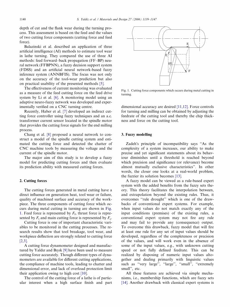
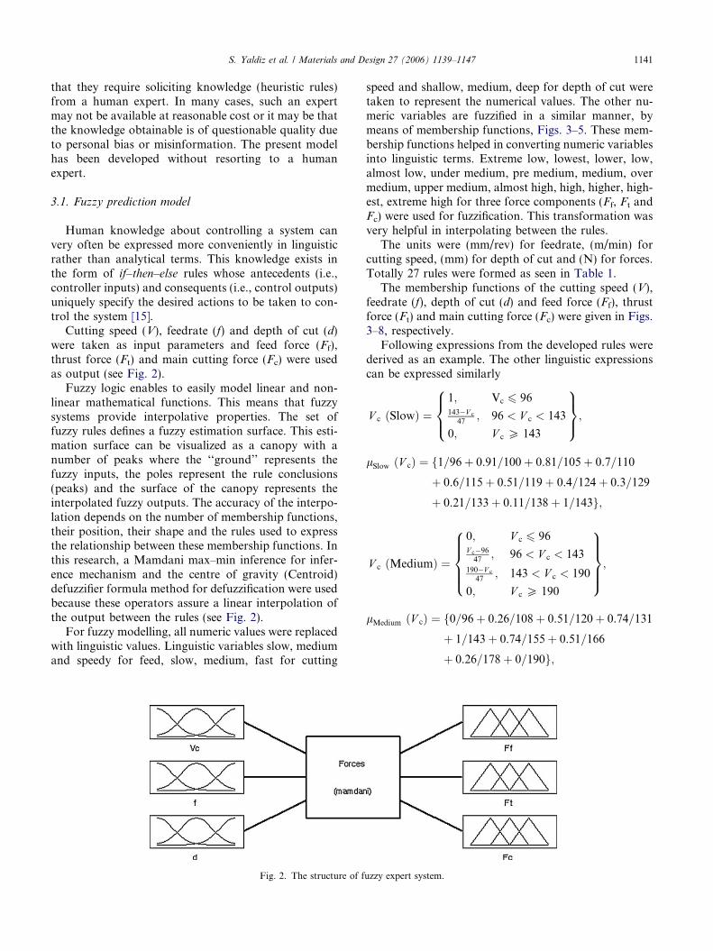
For fuzzy modelling, all numeric values were replacedwith linguistic values. Linguistic variables slow, mediumand speedy for feed, slow, medium, fast for cutting
Fig. 2. The structure of f
speed and shallow, medium, deep for depth of cut weretaken to represent the numerical values. The other nu-meric variables are fuzzified in a similar manner, bymeans of membership functions, Figs. 3–5. These mem-bership functions helped in converting numeric variablesinto linguistic terms. Extreme low, lowest, lower, low,almost low, under medium, pre medium, medium, overmedium, upper medium, almost high, high, higher, high-est, extreme high for three force components (Ff, Ft andFc) were used for fuzzification. This transformation wasvery helpful in interpolating between the rules.
The units were (mm/rev) for feedrate, (m/min) forcutting speed, (mm) for depth of cut and (N) for forces.Totally 27 rules were formed as seen in Table 1.
The membership functions of the cutting speed (V),feedrate (f), depth of cut (d) and feed force (Ff), thrustforce (Ft) and main cutting force (Fc) were given in Figs.3–8, respectively.
Following expressions from the developed rules werederived as an example. The other linguistic expressionscan be expressed similarly
V c ðSlowÞ ¼1; Vc 6 96143�V c
47; 96 < V c < 143
0; V c P 143
8><>:
9>=>;;
lSlow ðV cÞ ¼ f1=96þ 0.91=100þ 0.81=105þ 0.7=110
þ 0.6=115þ 0.51=119þ 0.4=124þ 0.3=129
þ 0.21=133þ 0.11=138þ 1=143g;
V c ðMediumÞ ¼
0; V c 6 96V c�96
47; 96 < V c < 143
190�V c
47; 143 < V c < 190
0; V c P 190
8>>><>>>:
9>>>=>>>;;
lMedium ðV cÞ ¼ f0=96þ 0.26=108þ 0.51=120þ 0.74=131
þ 1=143þ 0.74=155þ 0.51=166
þ 0.26=178þ 0=190g;
uzzy expert system.
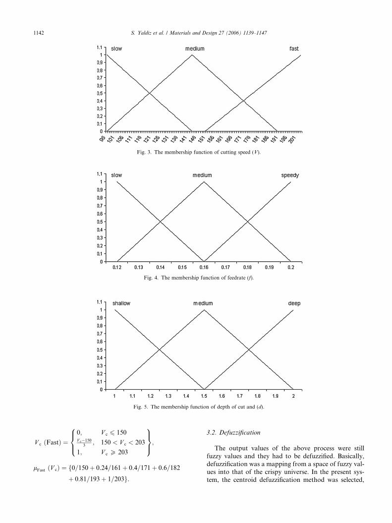
Fig. 3. The membership function of cutting speed (V).
Fig. 4. The membership function of feedrate (f).
Fig. 5. The membership function of depth of cut and (d).
1142 S. Yaldiz et al. / Materials and Design 27 (2006) 1139–1147
V c ðFastÞ ¼0; V c 6 150V c�150
3; 150 < V c < 203
1; V c P 203
8><>:
9>=>;;
lFast ðV cÞ ¼ f0=150þ 0.24=161þ 0.4=171þ 0.6=182
þ 0.81=193þ 1=203g.
3.2. Defuzzification
The output values of the above process were stillfuzzy values and they had to be defuzzified. Basically,defuzzification was a mapping from a space of fuzzy val-ues into that of the crispy universe. In the present sys-tem, the centroid defuzzification method was selected,
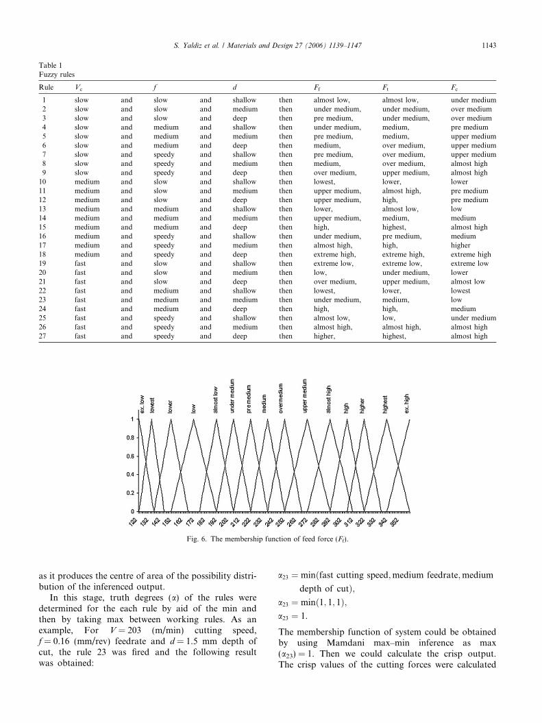
Table 1Fuzzy rules
Rule Vc f d Ff Ft Fc
1 slow and slow and shallow then almost low, almost low, under medium2 slow and slow and medium then under medium, under medium, over medium3 slow and slow and deep then pre medium, under medium, over medium4 slow and medium and shallow then under medium, medium, pre medium5 slow and medium and medium then pre medium, medium, upper medium6 slow and medium and deep then medium, over medium, upper medium7 slow and speedy and shallow then pre medium, over medium, upper medium8 slow and speedy and medium then medium, over medium, almost high9 slow and speedy and deep then over medium, upper medium, almost high
10 medium and slow and shallow then lowest, lower, lower11 medium and slow and medium then upper medium, almost high, pre medium12 medium and slow and deep then upper medium, high, pre medium13 medium and medium and shallow then lower, almost low, low14 medium and medium and medium then upper medium, medium, medium15 medium and medium and deep then high, highest, almost high16 medium and speedy and shallow then under medium, pre medium, medium17 medium and speedy and medium then almost high, high, higher18 medium and speedy and deep then extreme high, extreme high, extreme high19 fast and slow and shallow then extreme low, extreme low, extreme low20 fast and slow and medium then low, under medium, lower21 fast and slow and deep then over medium, upper medium, almost low22 fast and medium and shallow then lowest, lower, lowest23 fast and medium and medium then under medium, medium, low24 fast and medium and deep then high, high, medium25 fast and speedy and shallow then almost low, low, under medium26 fast and speedy and medium then almost high, almost high, almost high27 fast and speedy and deep then higher, highest, almost high
Fig. 6. The membership function of feed force (Ff).
S. Yaldiz et al. / Materials and Design 27 (2006) 1139–1147 1143
as it produces the centre of area of the possibility distri-bution of the inferenced output.
In this stage, truth degrees (a) of the rules weredetermined for the each rule by aid of the min andthen by taking max between working rules. As anexample, For V = 203 (m/min) cutting speed,f = 0.16 (mm/rev) feedrate and d = 1.5 mm depth ofcut, the rule 23 was fired and the following resultwas obtained:
a23 ¼ minðfast cutting speed;medium feedrate;medium
depth of cutÞ;a23 ¼ minð1; 1; 1Þ;a23 ¼ 1.
The membership function of system could be obtainedby using Mamdani max–min inference as max(a23) = 1. Then we could calculate the crisp output.The crisp values of the cutting forces were calculated
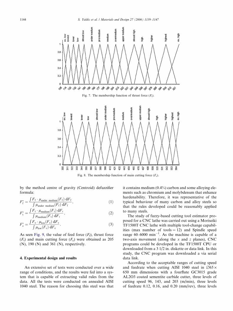
Fig. 8. The membership function of main cutting force (Fc).
Fig. 7. The membership function of thrust force (Ft).
1144 S. Yaldiz et al. / Materials and Design 27 (2006) 1139–1147
by the method centre of gravity (Centroid) defuzzifierformula:
F �f ¼R
F f � lunder mediumðF fÞ dF fRlunder mediumðF fÞ dF f
; ð1Þ
F �t ¼R
F t � lmediumðF tÞ dF tRlmediumðF tÞ dF t
; ð2Þ
F �c ¼R
F c � llowðF cÞ dF cRllowðF cÞ dF c
. ð3Þ
As seen Fig. 9, the value of feed force (Ff), thrust force(Ft) and main cutting force (Fc) were obtained as 205(N), 190 (N) and 361 (N), respectively.
4. Experimental design and results
An extensive set of tests were conducted over a widerange of conditions, and the results were fed into a sys-tem that is capable of extracting valid rules from thedata. All the tests were conducted on annealed AISI1040 steel. The reason for choosing this steel was that
it contains medium (0.4%) carbon and some alloying ele-ments such as chromium and molybdenum that enhancehardenability. Therefore, it was representative of thetypical behaviour of many carbon and alloy steels sothat the rules developed could be reasonably appliedto many steels.
The study of fuzzy-based cutting tool estimator pro-posed for a CNC lathe was carried out using a MoriseikiTF1500T CNC lathe with multiple tool-change capabil-ities (max number of tools = 12) and Spindle speedrange 60–6000 min�1. As the machine is capable of atwo-axis movement (along the x and z planes), CNCprograms could be developed in the TF1500T CPU ordownloaded from a 3 1/2 in. diskette or data link. In thisstudy, the CNC program was downloaded a via serialdata link.
According to the acceptable ranges of cutting speedand feedrate when cutting AISI 1040 steel in B65 ·650 mm dimensions with a fourflute GC3015 gradeAL2O3 coated sementite carbide cutter, three levels ofcutting speed 96, 143, and 203 (m/min), three levelsof feedrate 0.12, 0.16, and 0.20 (mm/rev), three levels
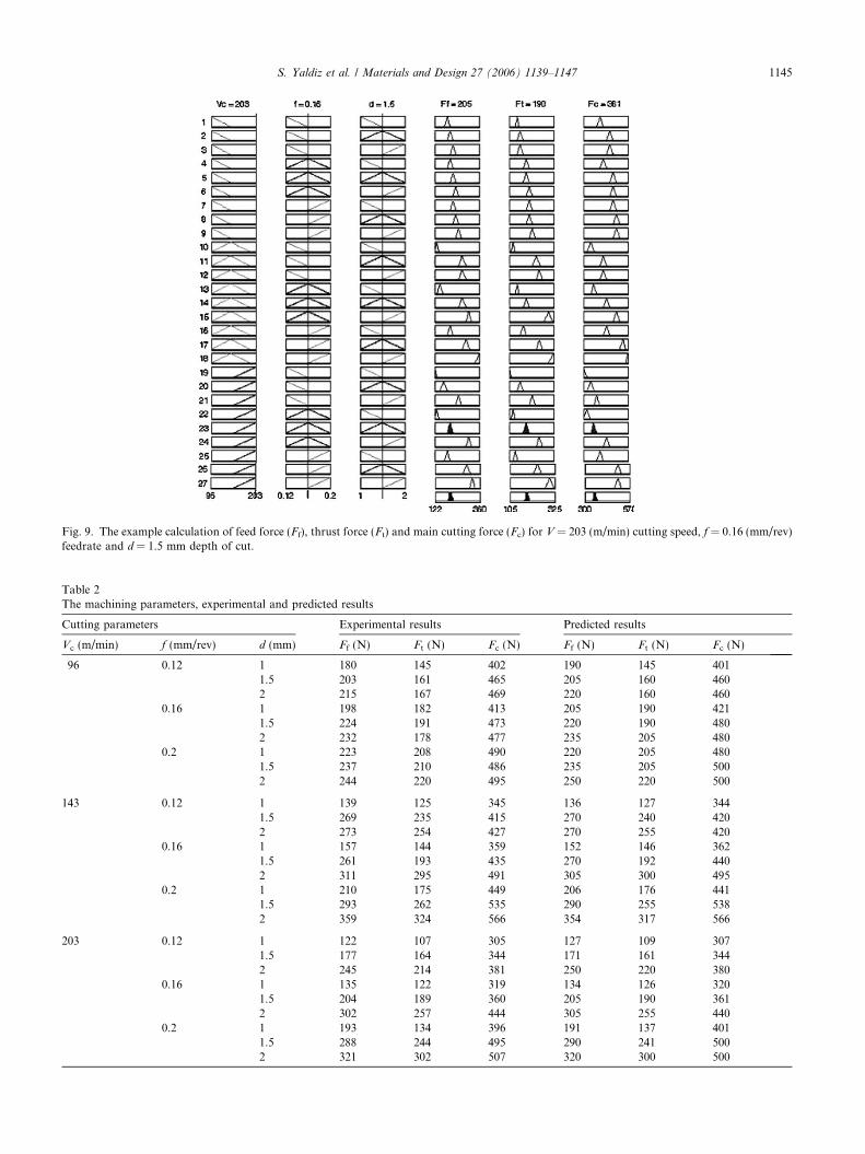
Fig. 9. The example calculation of feed force (Ff), thrust force (Ft) and main cutting force (Fc) for V = 203 (m/min) cutting speed, f = 0.16 (mm/rev)feedrate and d = 1.5 mm depth of cut.
Table 2The machining parameters, experimental and predicted results
Cutting parameters Experimental results Predicted results
Vc (m/min) f (mm/rev) d (mm) Ff (N) Ft (N) Fc (N) Ff (N) Ft (N) Fc (N)
96 0.12 1 180 145 402 190 145 4011.5 203 161 465 205 160 4602 215 167 469 220 160 460
0.16 1 198 182 413 205 190 4211.5 224 191 473 220 190 4802 232 178 477 235 205 480
0.2 1 223 208 490 220 205 4801.5 237 210 486 235 205 5002 244 220 495 250 220 500
143 0.12 1 139 125 345 136 127 3441.5 269 235 415 270 240 4202 273 254 427 270 255 420
0.16 1 157 144 359 152 146 3621.5 261 193 435 270 192 4402 311 295 491 305 300 495
0.2 1 210 175 449 206 176 4411.5 293 262 535 290 255 5382 359 324 566 354 317 566
203 0.12 1 122 107 305 127 109 3071.5 177 164 344 171 161 3442 245 214 381 250 220 380
0.16 1 135 122 319 134 126 3201.5 204 189 360 205 190 3612 302 257 444 305 255 440
0.2 1 193 134 396 191 137 4011.5 288 244 495 290 241 5002 321 302 507 320 300 500
S. Yaldiz et al. / Materials and Design 27 (2006) 1139–1147 1145
100
150
200
250
300
350
400
450
500
550
600
1 1.5 2 1 1.5 2 1 1.5 2 1 1.5 2 1 1.5 2 1 1.5 2 1 1.5 2 1 1.5 2 1 1.5 2
0.12 0.12 0.12 0.16 0.16 0.16 0.2 0.2 0.2 0.12 0.12 0.12 0.16 0.16 0.16 0.2 0.2 0.2 0.12 0.12 0.12 0.16 0.16 0.16 0.2 0.2 0.2
96 96 96 96 96 96 96 96 96 143 143 143 143 143 143 143 143 143 203 203 203 203 203 203 203 203 203
d (mm). f(mm/rev). Vc (m/min)
Fc
(N)
Fc Experimental Fc Predicted
Ff Experimental Ff Predicted
Ft Experimental Ft Predicted
Fig. 10. The differences between experimental and calculated results.
1146 S. Yaldiz et al. / Materials and Design 27 (2006) 1139–1147
of depth of cut 1, 1.5 and 2 (mm) were determined. The‘‘actual’’ cutting forces were measured in Newton (N) bythe cutting force dynamometer. Machining parametersused in the experiments and obtained results were givenin Table 2.
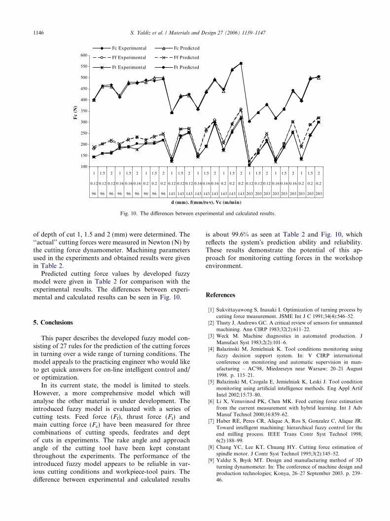
Predicted cutting force values by developed fuzzymodel were given in Table 2 for comparison with theexperimental results. The differences between experi-mental and calculated results can be seen in Fig. 10.
5. Conclusions
This paper describes the developed fuzzy model con-sisting of 27 rules for the prediction of the cutting forcesin turning over a wide range of turning conditions. Themodel appeals to the practicing engineer who would liketo get quick answers for on-line intelligent control and/or optimization.
In its current state, the model is limited to steels.However, a more comprehensive model which willanalyse the other material is under development. Theintroduced fuzzy model is evaluated with a series ofcutting tests. Feed force (Ff), thrust force (Ft) andmain cutting force (Fc) have been measured for threecombinations of cutting speeds, feedrates and deptof cuts in experiments. The rake angle and approachangle of the cutting tool have been kept constantthroughout the experiments. The performance of theintroduced fuzzy model appears to be reliable in var-ious cutting conditions and workpiece-tool pairs. Thedifference between experimental and calculated results
is about 99.6% as seen at Table 2 and Fig. 10, whichreflects the system�s prediction ability and reliability.These results demonstrate the potential of this ap-proach for monitoring cutting forces in the workshopenvironment.
References
[1] Sukvittayawong S, Inasaki I. Optimization of turning process bycutting force measurement. JSME Int J C 1991;34(4):546–52.
[2] Tlusty J, Andrews GC. A critical review of sensors for unmannedmachining. Ann CIRP 1983;32(2):611–22.
[3] Weck M. Machine diagnostics in automated production. JManufact Syst 1983;2(2):101–6.
[4] Balazinski M, Jemielniak K. Tool conditions monitoring usingfuzzy decision support system. In: V CIRP internationalconference on monitoring and automatic supervision in man-ufacturing – AC�98, Miedzeszyn near Warsaw; 20–21 August1998. p. 115–21.
[5] Balazinski M, Czogala E, Jemielniak K, Leski J. Tool conditionmonitoring using artificial intelligence methods. Eng Appl ArtifIntel 2002;15:73–80.
[6] Li X, Venuvinod PK, Chen MK. Feed cutting force estimationfrom the current measurement with hybrid learning. Int J AdvManuf Technol 2000;16:859–62.
[7] Haber RE, Peres CR, Alique A, Ros S, Gonzalez C, Alique JR.Toward intelligent machining: hierarchical fuzzy control for theend milling process. IEEE Trans Contr Syst Technol 1998;6(2):188–99.
[8] Chang YC, Lee KT, Chuang HY. Cutting force estimation ofspindle motor. J Contr Syst Technol 1995;3(2):145–52.
[9] Yaldız S, Bıyık MT. Design and manufacturing method of 3Dturning dynamometer. In: The conference of machine design andproduction technologies; Konya, 26–27 September 2003. p. 239–46.

S. Yaldiz et al. / Materials and Design 27 (2006) 1139–1147 1147
[10] Byrne G, Dornfled D, Inasaki I, Ketteler G, Konig W,Teti R. Tool condition monitoring (TCM) – the status ofresearch and industrial application. Ann CIRP 1995;44(2):541–567.
[11] Michalewicz Z. Genetic algorithms + data structures = evolutionprograms. Berlin: Springer; 1992.
[12] Tsitouras G, King RE. Rule-based neural control of a mecha-tronic system. Int J Intel Mechatron 1997;2(1):1–11.
[13] Zadeh LA. Outline of a new approach to the analysis of complexsystems and decision processes. IEEE Trans Syst Man and Cyb1973;3(1):28–44.
[14] Ali YM, Zhang L. A methodology for fuzzy modelling ofengineering systems. Fuzzy Set Syst 2001;118(2):181–97.
[15] Goggos V, Stathaki A, King RE. Evolutionary computation inthe design of optimized neural controllers. In: Proceedings of theECC99, Karlsruhe; 1999. p. 1–5.