Embed Size (px)
Citation preview

Indian Journal of Engineering & Materials Sciences Vol. 18, August 2011, pp. 283-292
Comparison of bolted joints with two different clearance types
Ümran Esendemir* & Ayşe Öndürücü Department of Mechanical Engineering, Süleyman Demirel University, 32260 Isparta, Turkey
Received 27 July 2010; accepted 11 April 2011
In this study, bearing strengths of bolted joints with different clearances are compared. Woven-glass-epoxy prepreg composites are tested under two different bolt-bearing conditions. The geometry of the samples for bolted joints is suitably varied in order to find the limit for width-to-diameter (W/d) and edge distance-to-diameter ratios (E/d), which are necessary to avoid unsafe failure modes. Damage progression is examined using scanning electron microscope (SEM) on specimens with mixed (bearing+net tension) mode for different percentages of their ultimate failure load. It is observed that the clearance between the bolt and hole has an important influence on the failure load of mechanically fastened joints.
Keywords: Bolted-joints, Failure analysis, Scanning electron microscopy (SEM)
An understanding of bolted joint behaviour is essential to the design of efficient aerospace structures from carbon-fibre reinforced polymer materials. Maximum joint efficiencies in composite structures tend to be less than for metals, so poorly designed joints detract significantly from the weight advantage of composites over metals. In a typical manufacturing environment, the diameter of fasteners and holes will vary within certain allowed tolerances. The combination of bolt and hole tolerances will result in a range of allowable bolt-hole fits, which in composites are generally clearance rather than interference fits, due to concerns over damage caused to the composite during insertion of the fastener, and also possibly removal of the fastener during inspections1. The strength and failure modes of bolted joints have been shown to be significantly affected by relations between geometrical parameters such as the bolt diameter (d) bolt-hole diameter (D) laminate thickness (t) width (W) and edge distance (E)2-5. Other factors such as the stacking sequence2,6, clamping moment4-10 have been investigated and shown to be important for the joint strength. Studies on the effects of clearance have been performed in bolted joints1,3,4,11-18. A review of the investigations that have been made on the stress and strength analysis of mechanically fastened joints in fibre-reinforced plastics (FRP) was presented by Camanho and Matthews19. The experimental observations of the effects of joint geometry, ply-orientation, lay-up and
through-thickness pressure on the joint behaviour are described briefly for both single and multi-fastener joints. Xiao and Ishikawa20 conducted the experimental investigations in order to study the strength and failure of mechanically fastened composite joints. Their results show that the bearing failure can be outlined as a process of compressive damage accumulation, and can be macroscopically divided into the following four stages: damage onset, damage growth, local fracture and structural fracture. An experimental investigation was carried out on a fibreglass/aluminium (FGA) laminate in order to characterise its behaviour under pin and bolt-bearing conditions. Bearing tests were carried out on a fibreglass/aluminium laminate, varying the joint geometry and clamping pressure, in order to find the design conditions to be fulfilled for a safe failure mode21. Additionally, a review of the investigations that have been made on the mechanics of mechanically fastened joints in polymer-matrix composite structures was presented by Thoppul et al.22
In this study, bearing strengths of bolted joints with different clearances have been compared. Two different clearance types have been formed to investigate the effect of the clearance in composite bolted joints. All specimens were torqued to finger-tight (T = 0 Nm) conditions. For each type, load-displacement curves and bearing strengths were obtained according to different geometrical parameters. Furthermore, failure modes of bolted-joint specimen with different clearance were presented. The damage progression of specimens with
_____________ *Corresponding author (E-mail: [email protected])

INDIAN J ENG. MATER. SCI., AUGUST 2011
284
clearance was examined using scanning electron microscope (SEM).
Bolted Joint Configuration The geometry of composite specimen is shown in
Fig. 1. The dimensions of the specimen were chosen as W= 10, 15, 20, 25 mm, E= 5, 10, 15, 20, 25 mm, L= 80 mm, t= 1.45 mm. Two different clearance types were formed, as shown in Fig. 2.
The hole diameter of the composite specimen was 5 mm for Type-I; however, the hole diameter of the composite specimen was 5.2 mm for Type-II. For both types, the diameter of the hole of test fixture was 5.2 mm. A metric 5 bolt was used in the experimental study. The preload moment was obtained by finger-tightening (see Fig. 3).
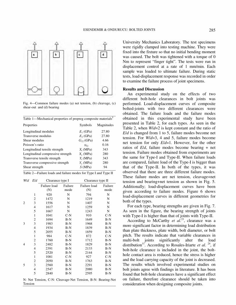
As seen in Fig. 4, there are failure modes related to the geometry of specimen: net tension, shear-out,
cleavage and bearing3. Although joint failure with the net-tension, shear-out and cleavage modes is catastrophic and immediate, bearing failure is progressive. For this reason, bearing failure is preferred in applications.
Bearing stress σb is defined by the following equation,
max
.σ =
b
P
D t ... (1)
Where maxP is the applied maximum load, D is the
hole diameter and t is the specimen thickness.
Experimental Procedure The mechanical properties of woven prepreg glass-
fibre composed of eight-layer composite blanks are given in Table 15.
All tests were conducted at ambient temperature by means of an Instron Testing Machine in Pamukkale
Fig. 2—Two different clearance types
Fig. 1—Geometry of the composite specimen
Fig. 3—Test fixture of bolted joints
ESENDEMIR & ONDURUCU: BOLTED JOINTS
285
University Mechanics Laboratory. The test specimens were rigidly clamped into testing machine. They were fixed into the fixture so that no initial bending moment was caused. The bolt was tightened with a torque of 0 Nm to represent “finger tight”. The tests were run in displacement control at a rate of 1 mm/min. Each sample was loaded to ultimate failure. During static tests, load-displacement response was recorded in order to examine the failure process of joint specimens.
Results and Discussion
An experimental study on the effects of two different bolt-hole clearances in bolt joints was performed. Load-displacement curves of composite bolted-joints with two different clearances were obtained. The failure loads and the failure modes obtained in this experimental study have been presented in Table 2, for each types. As seen in the Table 2, when W/d=2 is kept constant and the ratio of E/d is changed from 1 to 5, failure modes become net tension. For W/d=3, 4 and 5, failure modes become net tension for only E/d=1. However, for the other ratios of E/d, failure modes become bearing + net tension. Failure modes obtained from experiments are the same for Type-I and Type-II. When failure loads are compared, failure load of the Type-I is bigger than that of the Type-II. In both of the types, it was observed that there are three different failure modes. These failure modes are net tension, cleavage+net tension and bearing+net tension as shown in Fig. 5. Additionally; load-displacement curves have been given according to failure modes. Figure 6 shows load-displacement curves in different geometries for both of the types.
For each type, bearing strengths are given in Fig. 7. As seen in the figure, the bearing strength of joints with Type-I is higher than that of joints with Type-II.
According to McCarthy et al.23, clearance was a more significant factor in determining load distribution than plate thickness, plate width, bolt diameter, or bolt pitch. The results indicate that variable clearances in multi-bolt joints significantly alter the load distribution11. According to Rosales-Iriarte et al. 24, if bolt-hole clearance is included in the joint, the bolt-hole contact area is reduced, hence the stress is higher and the load carrying capacity of the joint is decreased. The results which involved experimental studies on bolt joints agree with findings in literature. It has been found that bolt-hole clearances have a significant effect on failure, therefore clearance should be taken into consideration when designing composite joints.
Fig. 4—Common failure modes (a) net tension, (b) cleavage, (c) shear-out and (d) bearing
Table 1—Mechanical properties of prepreg composite materials5
Properties Symbols Magnitudes
Longitudinal modulus E1 (GPa) 27.80 Transverse modulus E2 (GPa) 27.80 Shear modulus G12 (GPa) 4.66 Poisson’s ratio υ12 0.16
Longitudinal tensile strength Xt (MPa) 343 Longitudinal compressive strength Xc (MPa) 280 Transverse tensile strength Yt (MPa) 343 Transverse compressive strength Yc (MPa) 280 Shear strength S (MPa) 94
Table 2—Failure loads and failure modes for Type I and Type II
Clearance type I Clearance type II W/d E/d
Failure load (N)
Failure mode
Failure load (N)
Failure mode
2
1 2 3 4 5
920 1472 1556 1617 1667
N N N N N
794 1219 1407 1259 1243
N N N N N
3
1 2 3 4 5
1041 1694 1983 1934 2055
C-N B-N B-N B-N B-N
910 1649 1968 1839 1859
C-N B-N B-N B-N B-N
4
1 2 3 4 5
984 1760 2482 2391 2520
C-N B-N B-N B-N B-N
872 1712 1829 2133 2144
C-N B-N B-N B-N B-N
5
1 2 3 4 5
1081 2050 2560 2547 2840
C-N B-N B-N B-N B-N
927 1763 2291 2080 2595
C-N B-N B-N B-N B-N
N: Net Tension, C-N: Cleavage-Net Tension, B-N: Bearing-Net Tension

INDIAN J ENG. MATER. SCI., AUGUST 2011
286
Fig. 5—Load-displacemet curves for different failure modes in experimental study

ESENDEMIR & ONDURUCU: BOLTED JOINTS
287
Fig. 6—Load-displacemet curves according to different geometrical parameters for (a) clearance type-I and (b) clearance type-II

INDIAN J ENG. MATER. SCI., AUGUST 2011
288
Damage progression To investigate the damage progression of the
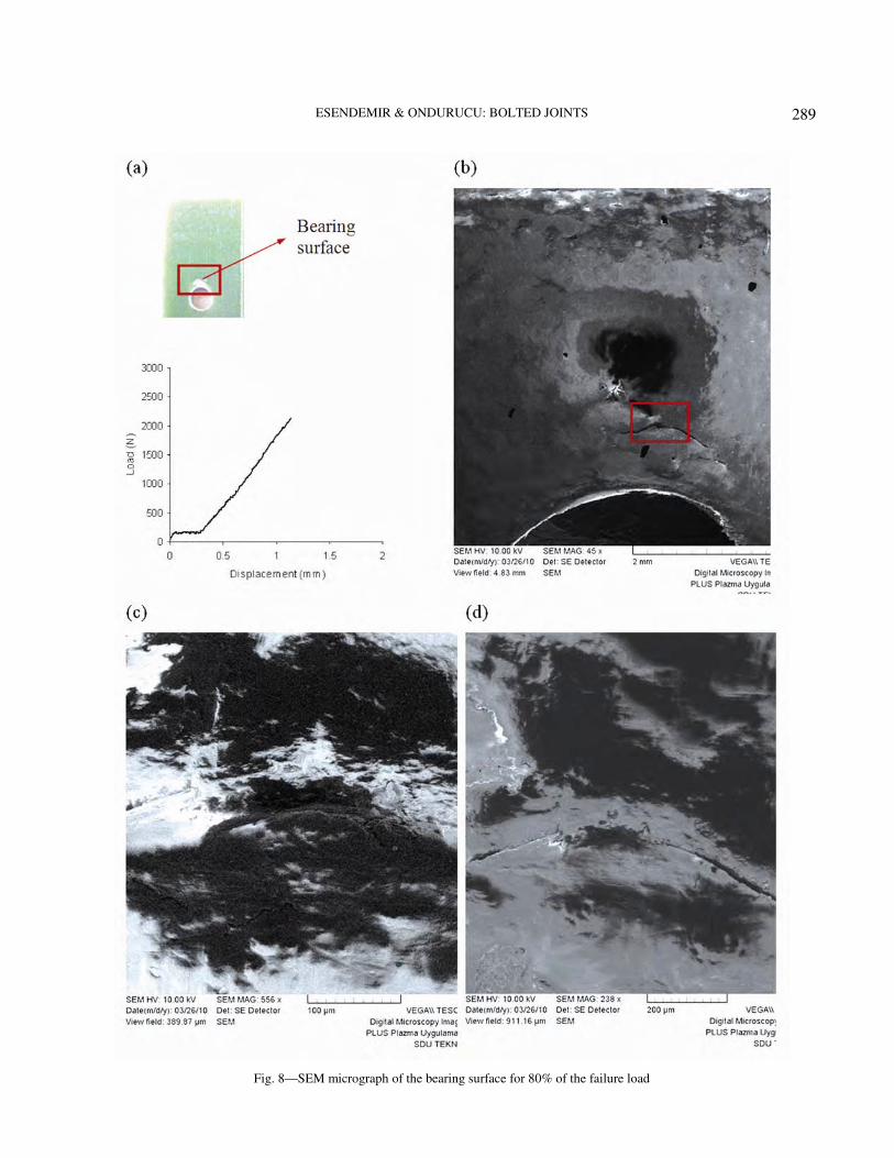
bearing surface of the specimens, samples were subjected to 80%, 95% and 100% of the ultimate failure loads. The damage areas were observed from the test samples under a scanning electron microscope (SEM) for 80%, 95% and 100% values of the failure load. Figures 8-10 show the progression of damage at the bearing surface of the specimens. As seen in Figs 8a, 9a and 10a, while failure type becomes bearing at 80% and 95% of the failure load, it becomes bearing and net tension at 100% ultimate failure load. From Fig. 8b, it can be seen that the piling up occurs in the matrix material and the cracks occur perpendicular to the loading direction. These types of orientations develop depending on the macro-displacements in matrix material after cracks have occurred. The details of the cracks are seen in Figs 8c and 8d. As shown in Fig. 9, thin and long cracks oriented perpendicular to
the loading direction occur at some areas of the bearing surface of the samples with 95% of the failure load. Additionally, it can be observed that other small cracks are either parallel or oriented at a certain angle to the main crack at the bearing surface. Figure 9d shows that matrix material piles up at some points, tearing off occurs and continues easily with the continuation of loading. As shown in Fig. 10, when the failure load is 100% in the samples, the net tension failure is observed at each side of the hole after the bearing failure mode has occurred. At the bearing surface of the samples with 100% of the failure load, the propagation of crack and accumulation of damage are bigger than that of the other values of the failure load.
Conclusions
In this study, a detailed experimental investigation was performed to evaluate the effect of clearance of mechanically fastened joints on two different types. The influence of failure loads, bearing strengths and failure modes of bolted joints were also investigated. Furthermore, damage progression of the sample was examined in order to predict joint failure. The following conclusions can be drawn from this study:
(i) Failure load and strength of the bolted joints depend on the joint geometry (W/d and E/d).
(ii) Bearing strengths of the woven-glass epoxy composite blanks generally increase by increasing both E/d and W/d ratios.
(iii) When the E/d ratio is 1, net tension, which is the weakest mode, occurs. Bearing+net tension mode compared with the other two failure modes has been found to have the highest ultimate strength. Therefore, optimum values of W/d and E/d ratios are preferred in the design.
(iv) The clearance between the bolt and hole has a significant influence on the failure load of bolted joints.
(v) Bearing strength of the Type-I is higher than that of the Type-II. Bearing strength of the Type-I increases by 35.72% according to Type-II at best (for W/d=4 and E/d=3).
(vi) When W/d ratio is equal to or greater than 3 for other ratios (except E/d=1) mixed failure mode (bearing+net tension) occurs. It is known that bearing + net tension failure mode is the best convenient mode because of load carrying capacity.
Fig. 7—Bearing strength according to different geometrical parameters for (a) clearance type-I and (b) clearance type-II.
ESENDEMIR & ONDURUCU: BOLTED JOINTS
289
Fig. 8—SEM micrograph of the bearing surface for 80% of the failure load

INDIAN J ENG. MATER. SCI., AUGUST 2011
290
Fig. 9—SEM micrograph of the bearing surface for 95% of the failure load

ESENDEMIR & ONDURUCU: BOLTED JOINTS
291
Fig. 10—SEM micrograph of the bearing surface for 100% of the failure load

INDIAN J ENG. MATER. SCI., AUGUST 2011
292
Acknowledgments The authors wish to express a special thank to
Izorell Firm, İzmir, Turkey, for their collaboration in producing of the woven glass-epoxy prepregs and to Pamukkale University Mechanical Engineering Department. References
1 McCarthy M A, Lawlor V P, Stanley W F & McCarthy C T, Compos Sci Technol, 62 (2002) 1415-1431.
2 Aktaş A & Dirikolu M H, Compos Struct, 62 (2003) 107-111.
3 Şen F, Pakdil M, Sayman O & Benli S, Mater Des, 29
(2008) 1159-1169. 4 Pakdil M, Şen F, Sayman O & Benli S, J Compos Mater,
26 (2007) 1239-1252. 5 Esendemir Ü, Adv Compos Lett, 17 (2008) 165-175. 6 Park H J, Compos Struct, 53 (2001) 213-221. 7 Oskouei R H & Chakherlou T N, Aerospace Sci Technol,
13 (2009) 325-330. 8 Chakherlou T N, Abazadeh B & Vogwell J, Eng Failure
Anal, 16 (2009) 242-253. 9 Chakherlou T N, Oskouei R H & Vogwell J, Eng Failure
Anal, 15 (2008) 563-574. 10 Khashaba U A, Sallam H E M, Compos Struct, 73 (2006)
310-317.
11 Lawlor V P, McCarthy M A & Stanley W F, Compos
Struct, 71 (2005) 176-190. 12 McCarthy M A & McCarthy C T, J Plast Rubber Compos,
32(2) (in-press). 13 Tong L, Composites Pt A, 31 (2000) 609-615. 14 McCarthy M A, Lawlor V P & Stanley W F, J Compos
Mater, 39 (2005) 799-825. 15 Kelly G & Hallström S, Compos Pt B: Eng, 35 (2004) 331-
343. 16 McCarthy C T & McCarthy M A, Compos Struct, 71
(2005) 159-175. 17 McCarthy M A & McCarthy C T, Plast Rubber Compos, 32
(2003) 65-70. 18 McCarthy C T, McCarthy M A & Lawlor V P, Compos Pt
B: Eng, 36 (2005) 290-305. 19 Camanho P P & Matthews F L, Composites Pt A, 28A
(1997) 529-547. 20 Xiao Y & Ishikawa T, Compos Sci Technol, 65 (2005)
1022-1031. 21 Caprino G, Squillace A, Giorleo G, Nele L & Rossi L,
Composites Pt A, 36 (2005) 1307-1315. 22 Thoppul S D, Finegan J & Gibson R F, Compos Sci
Technol, 69 (2009) 301-329. 23 McCarthy M A, McCarthy C T & Padhi G S, Compos
Struct, 73 (2006) 78-87. 24 Rosales-Iriarte F Fellows, N A & Durodola J F, Compos
Struct, 93 (2011) 1096-1102.


![Bolted Connections[1]](https://img.pdfslide.us/doc/110x75/54e7f8c84a7959704f8b46b8/bolted-connections1.jpg)


