Embed Size (px)
Citation preview

Saimaa University of Applied Sciences Faculty of Technology, Lappeenranta Double Degree Programme in Civil and Construction Engineering Aleksandr Arabov
Comparison of basic steel structures' calculations by SP and Eurocode Bachelor’s Thesis 2016
2
Abstract
Aleksandr Arabov Comparison of basic steel structures' calculations by SP and Eurocode, 37 pages, 1 appendix. Saimaa University of Applied Sciences Faculty of Technology, Lappeenranta Double Degree Programme in Civil and Construction Engineering Bachelor’s Thesis 2016 Instructors: Lecturer Petri Himmi
The purpose of the thesis work was to study how the basic steel structures are calculated according to Russian and European norms. All calculations were conducted according to actual norms of steel structures’ design (3-7). The thesis considers moment, shear and buckling resistance calculations, and also analysis of similarities and differences between European and Russian methods of design for steel I-beam.
The results of the study represent the step-by-step instruction for steel beam design with examples, which can be used by students of technical specialties or construction designers.
Keywords: steel structures, I-beam, Eurocode, SNiP, SP, Russian norms, basic calculations.

3
Content
1 Introduction ..................................................................................................... 4
2 Calculations .................................................................................................... 7
2.1 Initial data ........................................................................................... 7
2.2 Calculations by Eurocode .................................................................. 7
2.2.1 Classification of cross-sections .......................................................... 9
2.2.2 Moment resistance ........................................................................... 14
2.2.3 Shear resistance .............................................................................. 14
2.2.4 Lateral torsional buckling resistance ................................................ 15
2.2.5 Calculation of deflections ................................................................. 17
2.3 Calculations by SP ........................................................................... 19
2.3.1 Strength calculation .......................................................................... 19
2.3.2 Flexural stability calculations ............................................................ 22
3 Comparison .................................................................................................. 26
4 Conclusion .................................................................................................... 31
REFERENCES ................................................................................................. 32
APPENDICES ................................................................................................... 33
4
1 Introduction
SNiP (Building Standards and Rules) were emerged in the USSR in 1955 as a
set of provisions regulating design and construction processes. It was the first
system of normative documents in the field of construction in the USSR.
Nowadays, SNiP are divided into five sections of documents:
– Organization, management, economics
– Design standards
– Organization, production and acceptance of works
– Estimate standards
– Standards of material resources and labor costs
July 1, 2015 all of SNiP were canceled as mandatory and replaced by SP (Set
of Rules).
SP 16.13330.2011 “Steel structures” applies to design of steel structures of
buildings and constructions of different purposes, operating at temperatures
above than 60 °С and lower than 100 °С. The rules do not apply to the design
of steel structures of bridges, transport tunnels and culverts.
The Eurocodes are the set of harmonized technical standards specifying how
structural design should be conducted within the European Union. The
Eurocodes were developed by the European Committee for Standardization (1).
The purpose of the Eurocodes is to provide:
– a means to prove compliance with the requirements for mechanical
strength and stability and safety in case of fire established by European
Union law.
– a basis for construction and engineering contract specifications.
– a framework for creating harmonized technical specifications for building
products.
The first Eurocodes were published in 1984, and by 2002, ten sections have
been developed and published:

5
0. Basis of structural design (EN 1990)
1. Actions on structures (EN 1991)
2. Design of concrete structures (EN 1992)
3. Design of steel structures (EN 1993)
4. Design of composite steel and concrete structures (EN 1994)
5. Design of timber structures (EN 1995)
6. Design of masonry structures (EN 1996)
7. Geotechnical design (EN 1997)
8. Design of structures for earthquake resistance (EN 1998)
9. Design of aluminium structures (EN 1999)
In addition, each country has to have its own National Annex to the
Eurocodes that takes into account the features (e.g. snow load factors) of a
particular country.
EN 1993: “Design of steel structures” applies to the design of buildings and
other civil engineering works in steel. It complies with the principles and
requirements for the safety and serviceability of structures, the basis of their
design and verification that are given in EN 1990 – Basis of structural
design. EN 1993 is concerned with requirements for resistance,
serviceability, durability and fire resistance of steel structures.
EN 1993 is wider in scope than most of the other design EN Eurocodes due
to the diversity of steel structures, the need to cover both bolted and welded
joints and the possible slenderness of construction. EN 1993 has about 20
parts covering common rules, fire design, bridges, buildings, tanks, silos,
pipelined piling, crane supported structures, towers and masts, chimneys,
etc (2):
EN 1993-1-1:2005: General rules and rules for buildings
EN 1993-1-2:2005: General rules - Structural fire design
EN 1993-1-3:2006: General rules - Supplementary rules for cold-formed
members and sheeting

6
EN 1993-1-4:2006: General rules - Supplementary rules for stainless steels
EN 1993-1-5:2006: General rules - Plated structural elements
EN 1993-1-6:2007: Strength and stability of shell structures
EN 1993-1-7:2007: Strength and stability of planar plated structures subject
to out of plane loading
EN 1993-1-8:2005: Design of joints
EN 1993-1-9:2005: Fatigue
EN 1993-1-10:2005: Material toughness and through-thickness properties
EN 1993-1-11:2006: Design of structures with tension components
EN 1993-1-12:2007: General - High strength steels
EN 1993-2:2006: Steel bridges
EN 1993-3-1:2006: Towers, masts and chimneys – Towers and masts
EN 1993-3-2:2006: Towers, masts and chimneys – Chimneys
EN 1993-4-1:2007: Silos
EN 1993-4-2:2007: Tanks
EN 1993-4-3:2007: Pipelines
EN 1993-5:2007: Piling
EN 1993-6:2007: Crane supporting structures
The main objective of the study is to compare two different calculation
methods of basic structures in order to find similarities and differences
between them, which will help to simplify the cooperation of Russian and
EU engineers.

7
2 Calculations
2.1 Initial data
The example is the simply supported unrestrained beam in steel S275 located
in typical office building.
It is assumed that FEd (design loading on the structure) = 50 kN/m and the span
of the beam L = 6.0 m.
In this case, the maximum bending moment at the midspan will be:
My,Ed =FEdL2
8=
50 ∗ 62
8= 225 kNm
The maximum shear force nearby beam support:
VEd =FEdL
2=
50 ∗ 6
2= 150 kN
Calculation scheme with moment and shear diagrams shown in Figure 1.
Figure 1. Moment and shear diagrams
2.2 Calculations by Eurocode
In accordance to EN 1993, the required cross-section needs to have a plastic
modulus about the major axis (y-y) that is greater than:

8
Wel,y =My,Ed𝛾𝑀0
fy
where 𝛾𝑀0 – partial factor.
The following numerical values for partial factors γMi are recommended for
buildings:
γM0 = 1,00;
γM1 = 1,00;
γM2 = 1,25.
Assuming the nominal thickness of the element t≤40 mm, the yield strength is:
fy = 275 N/mm2
Wel,y =My,Ed𝛾𝑀0
fy=
225 ∗ 105 ∗ 1,0
275 ∗ 102= 818,2 𝑐𝑚3
From the tables of section dimensions and properties (10) check the cross-
section IPE 450, which has Wel,y = 1500 𝑐𝑚3.
Figure 2. Dimensions of the cross-section

9
Dimensions
h hw b tw tf R A d
mm mm mm mm mm mm mm2 mm
450,0 420,8 190,0 9,4 14,6 21,0 9880 378,8
Properties
G Iy Iz It Iw iz Wel,y Wpl,y
kg/m cm4 cm4 cm4 cm4 cm cm3 cm3
77,6 33740 1676 66,87 791,0 4,12 1500 1702
Table 1. Properties and dimensions of cross-section IPE 450
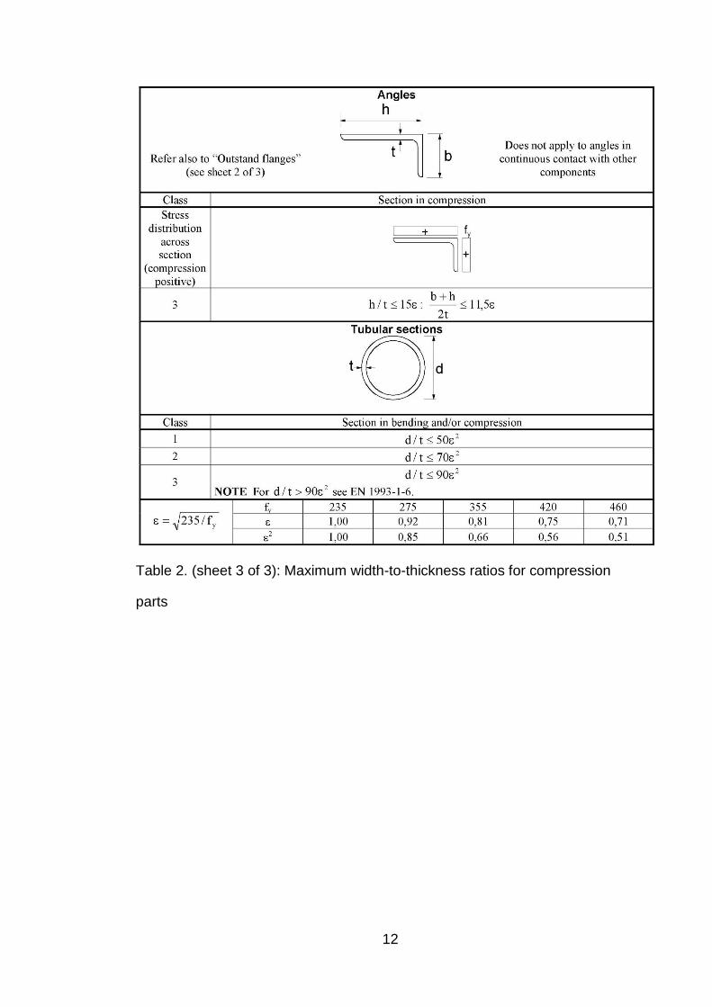
2.2.1 Classification of cross-sections
The role of cross section classification is to identify the extent to which the
resistance and rotation capacity of cross sections is limited by its local buckling
resistance (Table 2).
Assuming the section is class 1, then:
𝑐𝑓
𝑡𝑓≤ 9휀
where 휀 is determined by the formula:
휀 = √235
𝑓𝑦= √
235
275= 0,92
𝑐𝑓 – outstand flange (Figure 3), that is determined by the formula:
𝑐𝑓 =b
2−
𝑡𝑤
2− 𝑅 =
190
2−
9,4
2− 21,0 = 69,3 mm

10
Table 2. (sheet 1 of 3): Maximum width-to-thickness ratios for compression
parts

11
Table 2. (sheet 2 of 3): Maximum width-to-thickness ratios for compression
parts
12
Table 2. (sheet 3 of 3): Maximum width-to-thickness ratios for compression
parts

13
Figure 3. Outstand flange of a rolled cross-section
𝑐𝑓
𝑡𝑓≤ 9휀
63,9
14,6≤ 9 ∗ 0,92
4,75 ≤ 8,28
Therefore, the flange outstand in compression is Class 1.
In addition, it is necessary to check the internal compression part (Figure 4).
Figure 4. Internal compression part of a rolled cross-section
Class 1 section should satisfy:
𝑐𝑤
𝑡𝑤≤ 72휀
378,8
9,4≤ 72 ∗ 0,92

14
40,30 ≤ 66,24
Therefore, the section is Class 1.
2.2.2 Moment resistance
The design value of the bending moment MEd at each cross-section should
satisfy:
𝑀𝐸𝑑
𝑀𝑐,𝑅𝑑≤ 1,0
The design resistance for bending is:
𝑀𝑐,𝑅𝑑 = 𝑀𝑒𝑙,𝑅𝑑 =𝑊𝑒𝑙,𝑅𝑑𝑓𝑦
𝛾𝑀0
The 𝑊𝑒𝑙,𝑦 is using as a safe solution here and after, also allowed to use 𝑊𝑝𝑙,𝑦 for
class 1 cross-sections.
𝑀𝑐,𝑅𝑑 =1500 ∗ 103 ∗ 275
1,0∗ 10−3 Nm = 412500 Nm = 412,5 kNm
𝑀𝐸𝑑
𝑀𝑐,𝑅𝑑=
225 kNm
412,5 kNm= 0,55 < 1,0
2.2.3 Shear resistance
The design value of the shear force VEd at each cross section should satisfy:
𝑓𝑦/√3
𝛾𝑀0≥ 𝜏𝐸𝑑 =
𝑉𝐸𝑑 ∗ 𝑆
𝐼 ∗ 𝑡𝑤
where 𝑆 – first moment of area, it can be approximately calculated as:
𝑆 =𝑊𝑝𝑙,𝑦
2=
1702
2= 851 𝑐𝑚3
275/√3
1,0≥
150 ∗ 851
33740 ∗ 0,94
150 ∗ 103 ∗ 851 ∗ 1,0
33740 ∗ 0,94 ∗ 102 ∗ 275/√3≤ 1

15
0,25 ≤ 1
The shear resistance of the section is adequate.
Where the shear force 𝑉𝐸𝑑 is less than half the plastic shear resistance 𝑉𝑝𝑙,𝑅𝑑 its
effect on the moment resistance may be neglected.
2.2.4 Lateral torsional buckling resistance
A laterally unrestrained member subject to major axis bending should be
verified against lateral-torsional buckling as follows:
𝑀𝐸𝑑
𝑀𝑏,𝑅𝑑≤ 1,0
where MEd – design value of the moment
Mb,Rd – design buckling resistance moment.
The design buckling resistance moment of a laterally unrestrained beam should
be taken as:
𝑀𝑏,𝑅𝑑 = 𝜒𝐿𝑇𝑊𝑦
𝑓𝑦
𝛾𝑀1
where Wy – appropriate section modulus (Wy = Wpl,y for class 1 sections).
𝜒𝐿𝑇 – reduction factor for lateral-torsional buckling, which can be defined as:
𝜒𝐿𝑇 =1
Φ𝐿𝑇+√Φ𝐿𝑇2 −𝛽𝜆𝐿𝑇
2 but {
𝜒𝐿𝑇 ≤ 1,0
𝜒𝐿𝑇 ≤1
𝜆𝐿𝑇2
where Φ𝐿𝑇 is determined by formula:
Φ𝐿𝑇 = 0,5 [1 + 𝛼𝐿𝑇 (𝜆𝐿𝑇 − 𝜆𝐿𝑇,0) + 𝛽𝜆𝐿𝑇
2]
where αLT is an imperfection factor, for buckling curve type b the imperfection
factor is 0,34 (Table 3, 4);

16
Buckling curve a0 a b c d
Imperfection factor α 0,13 0,21 0,34 0,49 0,76
Table 3. Imperfection factors for buckling curves
Cross section Limits
Buckling
about
axis
Buckling curve
S 235
S 275
S 355
S 420
S 460
h/b
>1
,2 t𝑓 < 40 𝑚𝑚
y-y
z-z
a
b
a0
a0
t𝑓 ≤ 100 𝑚𝑚 y-y
z-z
b
c
a
a
h/b
≤1,2
t𝑓 ≤ 100 𝑚𝑚 y-y
z-z
b
c
a
a
t𝑓 > 100 𝑚𝑚 y-y
z-z
d
d
c
c
Table 4. Selection of buckling curve for a rolled cross-section
𝜆𝐿𝑇 – non-dimensional slenderness.
The following values for 𝜆𝐿𝑇,0 and 𝛽 are recommended for rolled sections or
equivalent welded sections:
𝜆𝐿𝑇,0 = 0,4 (maximum value);
𝛽 = 0,75 (minimum value).
𝜆𝐿𝑇 = √𝑊𝑦𝑓𝑦
𝑀𝑐𝑟
where Mcr is the elastic critical moment for lateral-torsional buckling.
𝑀𝑐𝑟 = 𝐶1
𝜋2𝐸𝐼𝑧
𝐿2√
𝐼𝑤
𝐼𝑧+
𝐿2𝐺𝐼𝑡
𝜋2𝐸𝐼𝑧

17
where G – the shear modulus (G = 80770 N/mm2);
E – Young’s modulus (E = 210000 N/mm2).
For distributed load on a simply supported beam C1 = 1,127.
𝐶1
𝜋2𝐸𝐼𝑧
𝐿2= 1,127 ∗
𝜋2 ∗ 210000 ∗ 106 ∗ 1674 ∗ 10−8
62= 1086360 𝑁 = 1086,36 𝑘𝑁
√𝐼𝑤
𝐼𝑧+
𝐿2𝐺𝐼𝑡
𝜋2𝐸𝐼𝑧= √
791 ∗ 10−12
1676 ∗ 10−8+
62 ∗ 80770 ∗ 106 ∗ 66,87 ∗ 10−8
𝜋2 ∗ 210000 ∗ 106 ∗ 1674 ∗ 10−8= 0,237 𝑚
𝑀𝑐𝑟 = 1086,36 ∗ 0,237 = 257260 𝑁𝑚 = 257,26 𝑘𝑁𝑚
Non-dimensional slenderness:
𝜆𝐿𝑇 = √𝑊𝑦𝑓𝑦
𝑀𝑐𝑟= √
1702 ∗ 10−6 ∗ 275 ∗ 106
257,26 ∗ 103= 1,35
Φ𝐿𝑇 = 0,5 ∗ [1 + 0,34 ∗ (1,35 − 0,4) + 0,75 ∗ 1,352] = 1,34
𝜒𝐿𝑇 =1
1,34 + √1,342 − 0,75 ∗ 1,352= 0,498
𝑀𝑏,𝑅𝑑 = 𝜒𝐿𝑇𝑊𝑦
𝑓𝑦
𝛾𝑀1= 0,498 ∗ 1702 ∗ 10−6 ∗
275 ∗ 106
1= 233165 𝑁𝑚
= 233,16 𝑘𝑁𝑚
Verification:
𝑀𝐸𝑑
𝑀𝑏,𝑅𝑑=
225
233,16= 0,96 < 1,0
Buckling resistance is adequate.
2.2.5 Calculation of deflections
The vertical deflection at the mid-span is determined by formula:
𝑓 = ∫𝑀𝐹𝑀1
𝐸𝐼𝑑𝑥
𝐿

18
where 𝑀1 – moment diagram by the load P = 1 (Figure 5);
𝑀𝐹 – moment diagram by the design load (Figure 1).
Figure 5. Moment diagram by the load P = 1
Integral can be calculated according to the Simpson’s rule:
𝑓 = ∫𝑀𝐹𝑀1
𝐸𝐼𝑑𝑥
𝐿
= ∑𝐿
6𝐸𝐼[𝑀1
𝑏𝑀𝐹
𝑏 + 4𝑀1
𝑚𝑀𝐹
𝑚 + 𝑀1
𝑒𝑀𝐹
𝑒]
where 𝑀1
𝑏, 𝑀𝐹
𝑏 – value of the moment at the beginning of section;
𝑀1
𝑚, 𝑀𝐹
𝑚 – value of the moment at the middle of section;
𝑀1
𝑒, 𝑀𝐹
𝑒 – value of the moment at the end of section.
Division the beam on the sections shown in Figure 6.
Figure 6. Division the beam on the sections
Vertical deflections should be calculated under the characteristic load
combination 𝐹𝐸𝐾 due to variable loads.
19
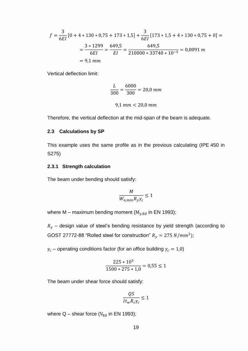
𝑓 =3
6𝐸𝐼[0 + 4 ∗ 130 ∗ 0,75 + 173 ∗ 1,5] +
3
6𝐸𝐼[173 ∗ 1,5 + 4 ∗ 130 ∗ 0,75 + 0] =
=3 ∗ 1299
6𝐸𝐼=
649,5
𝐸𝐼=
649,5
210000 ∗ 33740 ∗ 10−5= 0,0091 𝑚
= 9,1 𝑚𝑚
Vertical deflection limit:
𝐿
300=
6000
300= 20,0 𝑚𝑚
9,1 𝑚𝑚 < 20,0 𝑚𝑚
Therefore, the vertical deflection at the mid-span of the beam is adequate.
2.3 Calculations by SP
This example uses the same profile as in the previous calculating (IPE 450 in
S275)
2.3.1 Strength calculation
The beam under bending should satisfy:
𝑀
𝑊𝑛,𝑚𝑖𝑛𝑅𝑦𝛾𝑐≤ 1
where M – maximum bending moment (My,Ed in EN 1993);
𝑅𝑦 – design value of steel’s bending resistance by yield strength (according to
GOST 27772-88 “Rolled steel for construction” 𝑅𝑦 = 275 𝑁/𝑚𝑚2);
𝛾𝑐 – operating conditions factor (for an office building 𝛾𝑐 = 1,0)
225 ∗ 103
1500 ∗ 275 ∗ 1,0= 0,55 ≤ 1
The beam under shear force should satisfy:
𝑄𝑆
𝐼𝑡𝑤𝑅𝑠𝛾𝑐≤ 1
where Q – shear force (VEd in EN 1993);

20
𝑅𝑠 – design value of steel’s shear resistance that is determined by formula:
𝑅𝑠 = 0,58 ∗ 𝑅𝑦 = 0,58 ∗ 275 = 159,5 𝑁/𝑚𝑚2
It is important to note that factor 0,58 is approximately equal to 1/√3 from
European formula for shear capacity.
𝐼 – moment of inertia;
𝑆 – first moment of area (static moment), that value is usually given in Russian
section dimensions and properties tables. European tables do not contain the
first moment of area, so that it is necessary to calculate it for IPE 450.
S is also can be calculated using Wpl,y, as demonstrated above, but Russian
section dimensions and properties tables do not contain the values of Wpl,y.
The first moment of area for the area 𝐹 of any shape, and divided into n number
of very small, elemental areas 𝑑𝐹𝑖:
𝑆𝑥 = ∑ 𝑦𝑖𝑑𝐹𝑖
𝑛
𝑖=1
= ∫ 𝑦𝑑𝐹
𝐹
𝑆𝑦 = ∑ 𝑥𝑖𝑑𝐹𝑖
𝑛
𝑖=1
= ∫ 𝑥𝑑𝐹
𝐹
where 𝑥𝑖 and 𝑦𝑖 – distances to each elemental area measured from a given x-
y axis.
To determine the first moment of area it is necessary to consider the half of the
I-Profile, because the maximum value of shear stress τ located in the edge of
profile. For simplicity cross-section is divided into areas of a simple shape
(Figure 7).
21
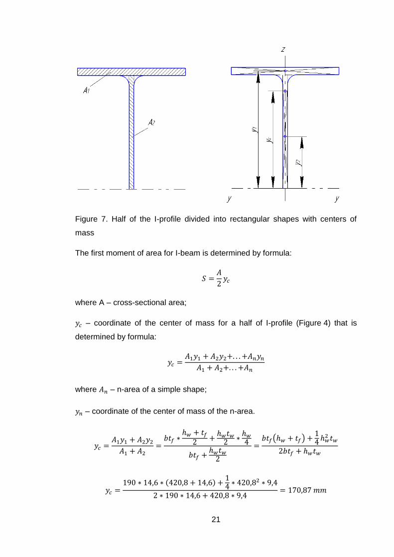
Figure 7. Half of the I-profile divided into rectangular shapes with centers of
mass
The first moment of area for I-beam is determined by formula:
𝑆 =𝐴
2𝑦𝑐
where A – cross-sectional area;
𝑦𝑐 – coordinate of the center of mass for a half of I-profile (Figure 4) that is
determined by formula:
𝑦𝑐 =𝐴1𝑦1 + 𝐴2𝑦2+. . . +𝐴𝑛𝑦𝑛
𝐴1 + 𝐴2+. . . +𝐴𝑛
where 𝐴𝑛 – n-area of a simple shape;
𝑦𝑛 – coordinate of the center of mass of the n-area.
𝑦𝑐 =𝐴1𝑦1 + 𝐴2𝑦2
𝐴1 + 𝐴2=
𝑏𝑡𝑓 ∗ℎ𝑤 + 𝑡𝑓
2 +ℎ𝑤𝑡𝑤
2 ∗ℎ𝑤
4
𝑏𝑡𝑓 +ℎ𝑤𝑡𝑤
2
=𝑏𝑡𝑓(ℎ𝑤 + 𝑡𝑓) +
14 ℎ𝑤
2 𝑡𝑤
2𝑏𝑡𝑓 + ℎ𝑤𝑡𝑤
𝑦𝑐 =190 ∗ 14,6 ∗ (420,8 + 14,6) +
14 ∗ 420,82 ∗ 9,4
2 ∗ 190 ∗ 14,6 + 420,8 ∗ 9,4= 170,87 𝑚𝑚

22
𝑆 =𝐴
2𝑦𝑐 =
9880
2∗ 170,87 = 844125,80 𝑚𝑚3 = 844,12 𝑐𝑚3
The resulting value of the first moment of area is approximate, because of the
flange to wall connection parts that are not taken into account.
𝑄𝑆
𝐼𝑡𝑤𝑅𝑠𝛾𝑐=
150 ∗ 103 ∗ 844,12
33740 ∗ 0,94 ∗ 102 ∗ 159,5 ∗ 1= 0,25 ≤ 1
Hence, shear resistance of the section is adequate.
2.3.2 Flexural stability calculations
𝑀𝑦
𝜑𝑏𝑊𝑦𝑅𝑦𝛾𝑐≤ 1
where 𝜑𝑏 – flexural stability factor, for calculation scheme shown in Figure 1 it is
determined by formula (for the case when part (flange) of the beam under load
is compressed):
[𝑓𝑜𝑟 (0,1 ≤ 𝛼 ≤ 40): 𝜑𝑏 = 1,60 + 0,08𝛼
𝑓𝑜𝑟 (40 < 𝛼 ≤ 400): 𝜑𝑏 = 3,15 + 0,04𝛼 − 2,7 ∗ 10−5𝛼2
where 𝛼 – factor that is defined by formula:
𝛼 = 1,54𝐼𝑡
𝐼𝑧(
𝑙𝑒𝑓
ℎ)
2
= 1,54 ∗66,87
1676∗ (
600
45)
2
= 10,92
where 𝑙𝑒𝑓 – effective length, for the beam without the intermediate stiffeners it is
assumed to be equal to the span of the beam.
Therefore, flexural stability factor is:
𝜑𝑏 = 1,60 + 0,08𝛼 = 1,60 + 0,08 ∗ 10,92 = 2,47
𝑀𝑦
𝜑𝑏𝑊𝑦𝑅𝑦𝛾𝑐=
225 ∗ 103
2,47 ∗ 1702 ∗ 275= 0,19 ≤ 1
Conditional slenderness of the flange under compression 𝜆𝑏 should be equal or
less than the limit slenderness 𝜆𝑢𝑏.
23
𝜆𝑏 = (𝑙𝑒𝑓
𝑏) √
𝑅𝑦𝑓
𝐸
Limit slenderness for the case when the upper flange is under load:
𝜆𝑢𝑏 = 0,35 + 0,0032𝑏/𝑡 + (0,76 − 0,02𝑏/𝑡 )𝑏/ℎ but {1 ≤ ℎ/𝑏 ≤ 6
15 ≤ 𝑏/𝑡 ≤ 35
where b and t – width and thickness of the compression flange;
h – distance (height) between the axes of the flanges.
1 ≤ ℎ/𝑏 ≤ 6
1 ≤ (450 − 14,6)/190 ≤ 6
1 ≤ 2,3 ≤ 6
15 ≤ 𝑏/𝑡 ≤ 35
𝑏/𝑡 = 13,0 < 15
When 𝑏/𝑡 < 15, need to take the value 𝑏/𝑡 = 15. Then limit slenderness is:
𝜆𝑢𝑏 = 0,35 + 0,0032 ∗ 15 + (0,76 − 0,02 ∗ 15) ∗190
450 − 14,6= 0,60
Conditional slenderness:
𝜆𝑏 = (6000
190) √
275
210000= 1,14
Flange stability is more than limit value, so it is necessary to install the
intermediate stiffeners for reduction of the effective length 𝑙𝑒𝑓.
Also it is necessary to check the slenderness of the wall 𝜆𝑤 that should be
equal or less than 2,5:
𝜆𝑤 = (ℎ𝑒𝑓
𝑡𝑤) √
𝑅𝑦𝑓
𝐸≤ 2,5
24
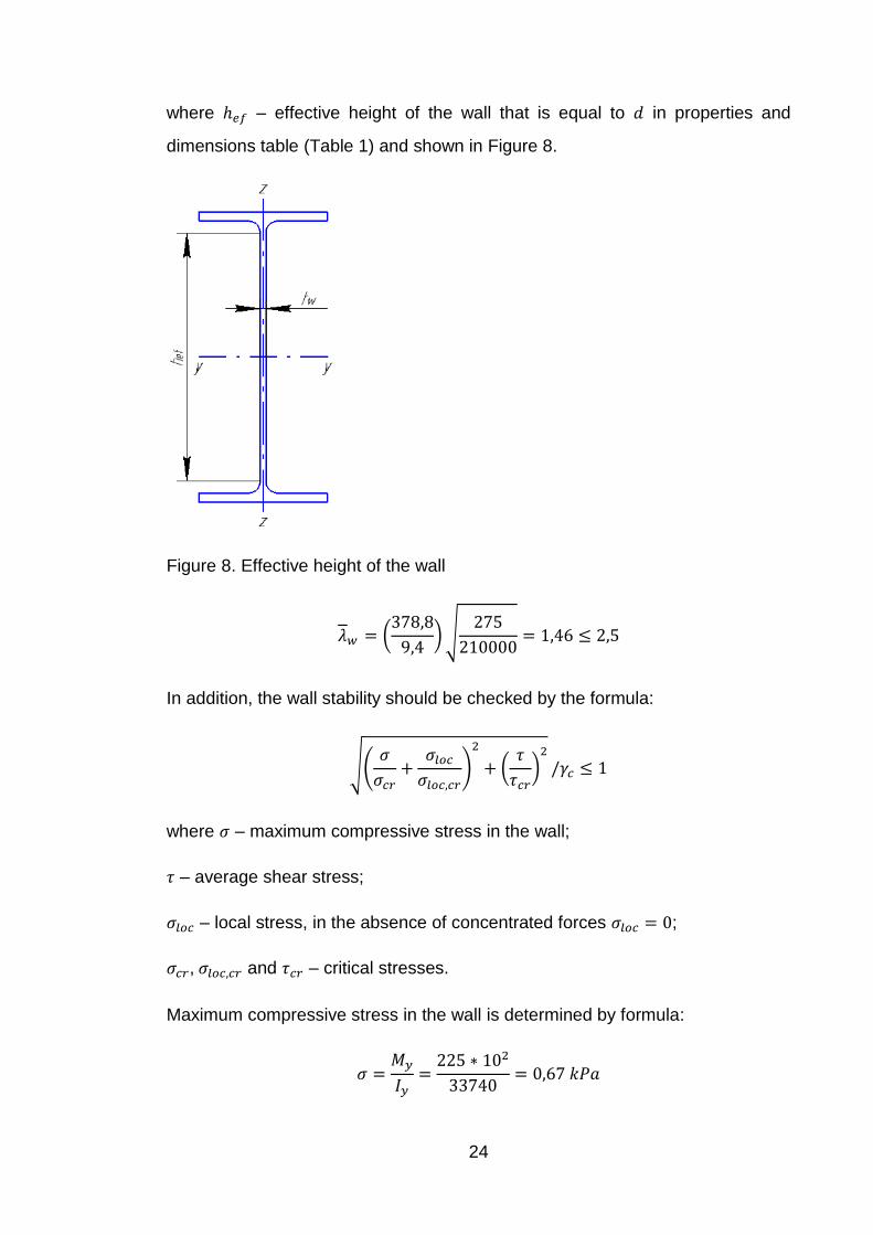
where ℎ𝑒𝑓 – effective height of the wall that is equal to 𝑑 in properties and
dimensions table (Table 1) and shown in Figure 8.
Figure 8. Effective height of the wall
𝜆𝑤 = (378,8
9,4) √
275
210000= 1,46 ≤ 2,5
In addition, the wall stability should be checked by the formula:
√(𝜎
𝜎𝑐𝑟+
𝜎𝑙𝑜𝑐
𝜎𝑙𝑜𝑐,𝑐𝑟)
2
+ (𝜏
𝜏𝑐𝑟)
2
/𝛾𝑐 ≤ 1
where 𝜎 – maximum compressive stress in the wall;
𝜏 – average shear stress;
𝜎𝑙𝑜𝑐 – local stress, in the absence of concentrated forces 𝜎𝑙𝑜𝑐 = 0;
𝜎𝑐𝑟, 𝜎𝑙𝑜𝑐,𝑐𝑟 and 𝜏𝑐𝑟 – critical stresses.
Maximum compressive stress in the wall is determined by formula:
𝜎 =𝑀𝑦
𝐼𝑦=
225 ∗ 102
33740= 0,67 𝑘𝑃𝑎
25
Average shear stress is determined by formula:
𝜏 =𝑄
𝑡𝑤ℎ𝑤=
150 ∗ 103
9,4 ∗ 420,8= 37,92 𝑀𝑃𝑎
Normal critical stress is determined by formula:
𝜎𝑐𝑟 =𝑐𝑐𝑟𝑅𝑦
𝜆𝑤
2
where 𝑐𝑐𝑟 – factor that is depends on factor 𝛿:
𝛿 = 𝛽 (𝑏𝑓
ℎ𝑒𝑓) (
𝑡𝑓
𝑡𝑤)
3
where 𝛽 – factor that is equal to 0,8.
𝛿 = 0,8 ∗ (190
378,8) ∗ (
14,6
9,4)
3
= 1,50
For welded connections and 𝛿 = 1,50, 𝑐𝑐𝑟 = 32,4, then:
𝜎𝑐𝑟 =32,4 ∗ 275
1,462= 4189,86 𝑁/𝑚𝑚2 = 4189,86 𝑀𝑃𝑎
Shear critical stress is determined by formula:
𝜏𝑐𝑟 = 10,3 (1 +0,76
𝜇) 𝑅𝑠/𝜆𝑤
2
where 𝜇 – the ratio of larger side of the wall compartment (the distance between
the intermediate stiffeners) to the lower, in the case of a beam without
intermediate stiffeners the ratio is 𝑙𝑒𝑓/ℎ𝑒𝑓.
𝜏𝑐𝑟 = 10,3 ∗ (1 +0,76 ∗ 378,8
6000) ∗ 159,5/1,462 = 809,61 𝑀𝑃𝑎
√(𝜎
𝜎𝑐𝑟+
𝜎𝑙𝑜𝑐
𝜎𝑙𝑜𝑐,𝑐𝑟)
2
+ (𝜏
𝜏𝑐𝑟)
2
/𝛾𝑐 = √(0,67 ∗ 10−3
4189,86)
2
+ (37,92
809,61)
2
/1 = 0,047 ≤ 1

26
3 Comparison
In this chapter will be the analysis of the main differences in the beam design
between SP and Eurocode norms. The differences between the typical I-beams
used in Russia and Finland also will be explained.
The resistance to the bending moment, as demonstrated above, is calculated
the same way for both standards:
𝑀𝑐,𝑅𝑑 =𝑊𝑦𝑓𝑦
𝛾𝑀0
As can be seen, for the same values of 𝛾𝑀0, the value of 𝑀𝑐,𝑅𝑑 depends only on
yield strength, which is characteristic of steel and 𝑊𝑦 that depends on the cross-
section shape. The values of yield strength in Finland and in Russia are the
same for one type of steel. Therefore, it is advisable to consider the differences
between cross-section shapes of typical I-beams.
The typical profiles of cross-sections in Russia slightly different from the Finnish
profiles. In Europe, hot rolled I-beams height varies from 80 mm to 600 mm, but
in Russia this value varies from 100 mm to 1013 mm. Some of profiles from
Russian dimensions and properties tables have analogues in European tables
(IPE 100 and 10Б1, IPE 200 and 20Б1), but most of them have not. If profile
has analogue, that is mean that shape and dimensions of cross-section are the
same for both European and Russian profiles. Therefore, in this case, the
values of 𝑊𝑦 are the same too.
Comparison of the resistance to bending moment 𝑀𝑐,𝑅𝑑 for Russian and
European I-beams with parallel flanges shown in Figure 9. The diagram reflects
both analyses elastic and plastic for EU profiles (IPE). The same diagram for
shear capacity 𝑉𝑐,𝑅𝑑 shown in Figure 10.

27
Fig
ure
9. V
alu
e o
f th
e r
esis
tan
ce
to b
en
din
g m
om
en
t M
Rd fo
r d
iffe
ren
t p
rofile
s

28
Fig
ure
10
. V
alu
e o
f th
e s
he
ar
resis
tan
ce V
Rd fo
r d
iffe
ren
t p
rofile
s

29
Formulas for determining of shear resistance are the same in both Russian and
European norms, except for value 1
√3, which is using in Eurocode’s formula
𝑓𝑦/√3
𝛾𝑀0≥ 𝜏𝐸𝑑 that rounded to 0,58. Therefore, there is no need to compare the two
calculation methods. However, it is possible to compare how to beam resists to
shear in two plastic and elastic conditions. The diagram (Figure 11)
demonstrates how ratio 𝑉𝐸𝑑
𝑉𝑐,𝑅𝑑 varies depending on the beam span.
Figure 11. Function 𝑓(𝐿) = 𝑉𝐸𝑑
𝑉𝑐,𝑅𝑑 in the elastic and plastic conditions
Methods of resistance to buckling calculation in two Russian and European
norms are quite different. But it is possible to compare the values of
slenderness 𝜆 (𝜆𝑏 in SP and 𝜆𝐿𝑇 in EN) for both cases. The Figure 12
demonstrates how to 𝜆 changes depending on the beam span for IPE 450.
0
0,2
0,4
0,6
0,8
1
1,2
1,4
3 6 9 12 15 18 21 24 27 30
VEd
/VC
,Rd
L, m
Safe solution

30
Figure 12. Function 𝑓(𝐿) = 𝜆 by EN and SP 𝑓(𝐿) = 𝜆𝐿𝑇 (𝐸𝑁)
0
1
2
3
4
5
6
3 6 9 12 15 18 21 24 27 30
Slen
der
nes
s
L, m
31
4 Conclusion
Results of the work:
1. Calculation of steel I-beam, which includes cross-section classification,
moment, shear and buckling resistance calculations and definition of deflections
according to actual both Russian and European norms.
2. Analysis of differences and similarities between design methods and between
Russian (Б) and European (IPE) I-beam profiles as well. Comparison of elastic
and plastic conditions is also include.
3. Step-by-step instruction for steel beam design that includes formulas and
references to chapters of Eurocode and SP.
The comparison of calculation methods shows that there is no any significant
difference between strength design (moment and shear capacity) for EN and
SP, except for various factors (partial, load, etc.). However, buckling calculation
methods are quite different and should be considered in more detail.

32
REFERENCES
1. Eurocodes. https://en.wikipedia.org/wiki/Eurocodes
2. http://eurocodes.jrc.ec.europa.eu/showpage.php?id=133
3. SP 20.13330.2011 “Loads and actions”
4. SP 16.13330.2011 “Steel structures”
5. EN 1993 “Design of steel structures”
6. EN 1990 “Basis of structural design”
7. EN 1991 “Actions on structures”
8. GOST 27772-88 “Rolled steel for construction”
9. SNiP 2-23-81 “Steel structures”
10. http://www.structural-drafting-net-expert.com/steel-sections-IPE.html
11. Gardner L, Nethercot D.A. Designers’ guide for to Eurocode 3: Design of
steel buildings. Thomas Telford, 2011.

APPENDICES
APPENDIX 1 Methods of calculating the beam under bending according EN and SP (sheet 1 of 5)
All calculations appropriate for class 1 I-beam with parallel flanges under bending. Calculation scheme shown in Figure 1.
EN SP
Design load
NA to EN 1990
“Basis of
structural design”
Definition of design value of load FEd
SP 20.13330.2011
“Loads and
actions”
Maximum bending moment and shear force
My,Ed =
FEdL2
8
VEd =FEdL
2
𝑀 =𝑞L2
8
VEd =𝑞L
2

34
APPENDIX 1 Methods of calculating the beam under bending according EN and SP (sheet 2 of 5)
Moment and shear resistance
EN 1993 “Design
of steel
structures” - 6.2.5
𝑀𝐸𝑑
𝑀𝑐,𝑅𝑑≤ 1,0
𝑀𝑐,𝑅𝑑 = 𝑀𝑒𝑙,𝑅𝑑 =𝑊𝑒𝑙,𝑅𝑑𝑓𝑦
𝛾𝑀0
𝑀
𝑊𝑛,𝑚𝑖𝑛𝑅𝑦𝛾𝑐≤ 1
𝑄𝑆
𝐼𝑡𝑤𝑅𝑠𝛾𝑐≤ 1
(𝑅𝑠 = 0,58 ∗ 𝑅𝑦)
𝑆 =𝐴
2𝑦𝑐
𝑦𝑐 =𝐴1𝑦1 + 𝐴2𝑦2+. . . +𝐴𝑛𝑦𝑛
𝐴1 + 𝐴2+. . . +𝐴𝑛
SP 16.13330.2011
“Steel structures” -
8.2.1
EN 1993 - 6.2.6 Plastic:
𝑉𝐸𝑑
𝑉𝑐,𝑅𝑑≤ 1,0
𝑉𝑐,𝑅𝑑 = 𝑉𝑝𝑙,𝑅𝑑 =𝐴𝑣(𝑓𝑦/√3)
𝛾𝑀0
𝐴𝑣 = 𝐴 − 2𝑏𝑡𝑓 + (𝑡𝑤 + 2𝑟)𝑡𝑓
(𝐴𝑣 ≥ 𝜂ℎ𝑤𝑡𝑤; 𝜂 = 1,0)
Elastic:
𝑓𝑦/√3
𝛾𝑀0≥ 𝜏𝐸𝑑 =
𝑉𝐸𝑑 ∗ 𝑆
𝐼 ∗ 𝑡𝑤
(𝑆 =𝑊𝑝𝑙,𝑦
2)

35
APPENDIX 1 Methods of calculating the beam under bending according EN and SP (sheet 3 of 5)
Buckling calculations
EN 1993 - 6.3.2.1 𝑀𝐸𝑑
𝑀𝑏,𝑅𝑑≤ 1,0
𝑀𝑏,𝑅𝑑 = 𝜒𝐿𝑇𝑊𝑦
𝑓𝑦
𝛾𝑀1
𝑀𝑦
𝜑𝑏𝑊𝑦𝑅𝑦𝛾𝑐≤ 1
[𝑓𝑜𝑟 (0,1 ≤ 𝛼 ≤ 40): 𝜑𝑏 = 1,60 + 0,08𝛼
𝑓𝑜𝑟 (40 < 𝛼 ≤ 400): 𝜑𝑏 = 3,15 + 0,04𝛼 − 2,7 ∗ 10−5𝛼2
𝛼 = 1,54𝐼𝑡
𝐼𝑧(
𝑙𝑒𝑓
ℎ)
2
SP 16.13330.2011
- 8.4.1
Annex Ж
(Table Ж.1)
EN 1993 - 6.3.2.3
(Tables 6.3, 6,5)
𝜒𝐿𝑇 =1
Φ𝐿𝑇+√Φ𝐿𝑇2 −𝛽𝜆𝐿𝑇
2 but {
𝜒𝐿𝑇 ≤ 1,0
𝜒𝐿𝑇 ≤1
𝜆𝐿𝑇2
Φ𝐿𝑇 = 0,5 [1 + 𝛼𝐿𝑇 (𝜆𝐿𝑇 − 𝜆𝐿𝑇,0)
+ 𝛽𝜆𝐿𝑇
2]
𝜆𝑏 ≤ 𝜆𝑢𝑏
𝜆𝑏 = (𝑙𝑒𝑓
𝑏) √
𝑅𝑦𝑓
𝐸
𝜆𝑢𝑏 = 0,35 + 0,0032𝑏/𝑡 + (0,76 − 0,02𝑏/𝑡 )𝑏/ℎ
but {1 ≤ ℎ/𝑏 ≤ 6
15 ≤ 𝑏/𝑡 ≤ 35
SP 16.13330.2011
- 8.4.4
(Table 11)

36
Buckling calculations
𝜆𝐿𝑇,0 = 0,4 (maximum value);
𝛽 = 0,75 (minimum value).
𝜆𝐿𝑇 = √𝑊𝑦𝑓𝑦
𝑀𝑐𝑟
𝑀𝑐𝑟 = 𝐶1
𝜋2𝐸𝐼𝑧
𝐿2√
𝐼𝑤
𝐼𝑧+
𝐿2𝐺𝐼𝑡
𝜋2𝐸𝐼𝑧
𝜆𝑤 = (ℎ𝑒𝑓
𝑡𝑤) √
𝑅𝑦𝑓
𝐸≤ 2,5
SP 16.13330.2011
- 8.5.1
√(𝜎
𝜎𝑐𝑟+
𝜎𝑙𝑜𝑐
𝜎𝑙𝑜𝑐,𝑐𝑟)
2
+ (𝜏
𝜏𝑐𝑟)
2
/𝛾𝑐 ≤ 1
𝜎𝑐𝑟 =𝑐𝑐𝑟𝑅𝑦
𝜆𝑤
2
SP 16.13330.2011
- 8.5.3
(Table 12)
𝜎 =
𝑀𝑦
𝐼𝑦
𝜏 =𝑄
𝑡𝑤ℎ𝑤
SP 16.13330.2011
- 8.5.2
𝛿 = 𝛽 (
𝑏𝑓
ℎ𝑒𝑓) (
𝑡𝑓
𝑡𝑤)
3
SP 16.13330.2011
- 8.5.4
𝜏𝑐𝑟 = 10,3 (1 +
0,76
𝜇) 𝑅𝑠/𝜆𝑤
2
SP 16.13330.2011
- 8.5.3
APPENDIX 1 Methods of calculating the beam under bending according EN and SP (sheet 4 of 5)
37
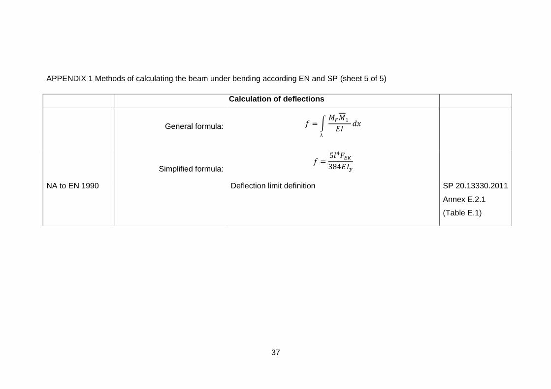
APPENDIX 1 Methods of calculating the beam under bending according EN and SP (sheet 5 of 5)
Calculation of deflections
General formula: 𝑓 = ∫𝑀𝐹𝑀1
𝐸𝐼𝑑𝑥
𝐿
Simplified formula: 𝑓 =
5𝑙4𝐹𝐸𝐾
384𝐸𝐼𝑦
NA to EN 1990 Deflection limit definition SP 20.13330.2011
Annex E.2.1
(Table E.1)