Embed Size (px)
Citation preview

International Journal of Advance Engineering and Research Development
Volume 3, Issue 5, May -2016
@IJAERD-2016, All rights Reserved 165
Scientific Journal of Impact Factor (SJIF): 4.14 e-ISSN (O): 2348-4470
p-ISSN (P): 2348-6406
COMPARISON OF BASE SHEAR AND LATERAL FORCE FOR FORCE
BASED DESIGN METHOD AND DISPLACEMENT BASED DESIGN METHOD
OF RC FRAME STRUCTURES
AKASH V. MODI1 , Dr. K. G. MEHTA2, D. N. SHETH3
1ME (Structural Engineering) Student,
Merchant Institute of Technology, Piludhara, Mehsana, India 2Principal, Merchant Engineering College, Basna, India
3Lecturer, Government Polytechnic, Palanpur, India
Abstract - The paper shows that an alternative design other than Forced-Based Design method for seismic design of
structures has been proposed, that is, Displacement-Based Design method. A three, six and nine storey building has been
taken for three different zones, that is, Zone III, Zone IV and Zone V and is designed with both the methods and their
respective base shear and design lateral force has been calculated. The design procedure has been elaborated and
comparison of base shear and design lateral force for both the procedure has been plotted. Finally concluding remarks has
been highlighted.
Keywords – Forced-Based Design Method: Seismic Coefficient Method, Displacement-Based Design Method, RC frame
building, Storey, Lateral force, Base shear.
I. INTRODUCTION When earthquakes occur, a building undergoes dynamic motion. This is because the building is subjected to inertia forces
that act in opposite direction to the acceleration of earthquake excitations. These inertia forces, called seismic loads, are
usually dealt with by assuming forces external to the building. Most seismic structural analyses are based on the relative-
displacements formulation where the base accelerations are used as the basic loading. Hence, experience with the direct use
of absolute earthquake displacement loading acting at the base of the structure has been limited. Several new types of
numerical errors associated with the use of absolute seismic displacement loading are identified. Those errors are inherent in
all methods of dynamic analysis and are directly associated with the application of displacement loading. It is possible for the
majority of seismic analyses of structures to use the ground accelerations as the basic input, and the structural displacements
produced are relative to the absolute ground displacements. For earthquake resistant design, evaluation of the seismic
performance of buildings, it is essential to determine if an acceptable solution in terms of capacity and performance is
achieved. Earthquake induced forces are direct functions of the energy absorption, damping and ultimate damage capacity of structural
members, which all depend on deformation. Modern constructions must satisfy seismic design criteria which are often
associated to the most adverse combination of actions with regard to building resistance under lateral loads.
The aim of this Paper is to compare two different design approaches: the Force-Based Design (FBD) and the Direct
Displacement-Based Design (DDBD).
II. FORCE BASED DESIGN
The force-based design, FBD, procedure is based on calculating the base shear force resulting from the earthquake dynamic
motion using the acceleration response spectrum and the expected elastic period of the building. In this procedure the static
loads are applied on a structure with magnitudes and directions that closely approximate the effects of dynamic loading
caused by earthquakes. Concentrated lateral forces due to dynamic loading tend occur at each floor in buildings, where
concentration of mass exists. Concentrated lateral forces tend to follow the fundamental mode shape of the building, in other
words it is larger at higher elevations in a structure. The greatest lateral displacements and the largest lateral forces often occur at the top level of a structure. These effects are modeled in equivalent static lateral force procedures of most design
codes by placing a force at each story level in the structure, which is directly proportional with the height. A Force based
design where characteristic material strength is used. It uses variable load combination:
1) 1.5(DL+LL),
2) 1.2(DL+LL±SL),
3) 1.5(DL±SL),
4) 0.9DL±1.5SL, Where DL stands for dead load, LL for imposed load and SL for seismic load along the frame.
2.1 Limitations of Force-Based Design are

International Journal of Advance Engineering and Research Development (IJAERD)
Volume 3, Issue 5, May -2016, e-ISSN: 2348 - 4470, print-ISSN: 2348-6406
@IJAERD-2016, All rights Reserved 166
The fundamental period required to start the design is determined using empirical expressions. The values specified for the
modification factor, R, by seismic codes, appear to be somewhat arbitrary. Displacements are checked at the end of the design
process only. There appears to be a lack of concern about the implied inelastic displacements which may be excessive and
contribute to the instability of the structure.
2.2 Design Spectrum
The design horizontal seismic coefficient Ah for a structure shall be determined by the following expression:
Ah = ZISa/2Rg
Where
Z = Zone factor , The factor 2 in the denominator of Z is used so as to reduce the Maximum Considered Earthquake ( MCE )
zone factor to the factor for Design Basis Earthquake ( DBE ). I = Importance factor, depending upon the functional use of the structures, characterized by. Hazardous consequences of its
failure, post-earthquake functional needs, historical value, or economic importance.
R = Response reduction factor, depending on the perceived seismic damage performance of the structure, characterized by
ductile or brittle deformations. However, the ratio (I/R) shall not be greater than 1.0.
2.3 Design Seismic Base Shear
The total design lateral force or design seismic base shear ( VB)along any principal direction shall be determined by
the following expression:
V = AhW
2.4 Fundamental Natural Period
The approximate fundamental natural period of vibration ( T, ), in seconds, of all other buildings, including moment
resisting frame buildings with brick infill panels, may be estimated by the empirical expression:
Ta = 0.09/d1/2
Where,
h = Height of building, in m
d = Base dimension of the building at the plinth level, in m, along the considered direction of the lateral force.
2.5 Distribution of Design Force
III. DIRECT DISPLACEMENT – BASED DESIGN
This approach uses the displacement response spectrum as a basis for calculating the base shear force. It also depends on
studying the building considering its inelastic phase. This is presents the fundamentals of the new seismic design method
known as Direct Displacement-Based Design (DDBD). It is considered as one of the simplest design approaches for analysis
of the multi-degree of freedom structures. In this method, the structure is characterized by the secant stiffness and equivalent
damping of an equivalent single degree of freedom structure. This design is based on achieving a specified displacement limit
state, defined either by material strain limits, or non-structural drift limits obtained from design codes under the design level
seismic intensity. The characterization of the structure using the substitute structure avoids many problems inherent in force-
based design, (FBD), where initial stiffness is used to determine an elastic period which is a drawback that is present in most
of the building codes. The design approach attempts to design a structure which would achieve, rather than be bounded by, a
given performance limit state under a given seismic intensity, essentially resulting in uniform-risk structures, which is philosophically compatible with the uniform-risk seismic spectra incorporated in most design codes. A Displacement based
design which uses expected material strength in the design stage. It also uses constant beam section for a particular frame.
It uses load combination as

International Journal of Advance Engineering and Research Development (IJAERD)
Volume 3, Issue 5, May -2016, e-ISSN: 2348 - 4470, print-ISSN: 2348-6406
@IJAERD-2016, All rights Reserved 167
1) DL+LL,
2) DL+LL±SLx
3) DL+LL±SLy
Fig. 1 Fundamentals of Displacement-Based Design (M. J. N. Priestley- Page 64)
3.1 Design Displacement Profile:- Design profiles are defined in the Model Code for regular structures by Priestley et.al. 2007, based on the results of Non-
linear Time History Analysis. For regular frame structures, the design displacement profile is given by,
Δᵢ=𝜔𝜃.𝜃𝑐.𝐻ᵢ.4𝐻𝑛− 𝐻ᵢ/4𝐻𝑛− 𝐻₁ (1)
Where,
ωθ = 1.15 – 0.0034Hn ≤ 1 is a reduction factor for higher mode amplification of drift
θc = Drift limit (0.02 for life safety perspective) [FEMA 356 (2002)]
The properties for single degree of freedom system is determined by, Design displacement of the equivalent SDOF structure is related to the storey displacements. It is given by,
𝛥𝑑=Ʃ (𝑚ᵢ𝛥ᵢ2)/Ʃ (𝑚ᵢ𝛥ᵢ) (2)
𝑚𝑒= Ʃ (𝑚ᵢ𝛥ᵢ)/Δ𝑑 (3)
𝐻𝑒= Ʃ (𝑚ᵢ𝛥ᵢ𝐻ᵢ)/Ʃ (𝑚ᵢ𝛥ᵢ) (4)
Where, mi, hi and Δi are respectively the mass, height from base and displacement for ith storey. Δd is target (spectral)
displacement, me is equivalent mass, He is the effective height of the ESDOF system.
The design displacement ductility factor is a relation between design displacement and yield displacement.
For reinforced concrete frames, yield drift can be developed from the yield curvature as,
𝜃𝑦=0.5𝜀𝑦.𝐿𝑑𝐻𝑏 (5) Yield displacement will be,
𝛥𝑦= 𝜃𝑦.𝐻𝑒 (6)
𝜇= Δ𝑑Δ𝑦 (7)
Equivalent damping for Concrete Frame building is dependent on design displacement ductility. It is given by:
𝜉𝑒𝑞=0.05+0.565.𝜇−1/𝜇𝜋 (8)
The effective period Te corresponding to Δd and ξeq is to be obtained from the design displacement spectra.
The effective stiffness Ke, of the substitute SDOF structure, derived from its effective mass me and effective period Te and
hence the base shear is obtained
𝐾𝑒=4𝜋²𝑚𝑒/𝑇𝑒² (9)
𝐹=𝑉𝑏𝑎𝑠𝑒=𝐾𝑒.Δ𝑑 (10 a)
Then the base shear force is distributed to the floor levels in proportion to the product of mass and displacement as,
𝐹𝑖=𝐹𝑡+𝑉𝑏.𝑚𝑖Δ𝑖/Ʃ (𝑚𝑖𝛥𝑖) (10 b)
Where,
Ft = 0.1Vb (at roof) and 0 (at all floors)

International Journal of Advance Engineering and Research Development (IJAERD)
Volume 3, Issue 5, May -2016, e-ISSN: 2348 - 4470, print-ISSN: 2348-6406
@IJAERD-2016, All rights Reserved 168
IV. LITERATURE REVIEW
Damir Dzakic, Ivan Kraus, Dragan Moric[1] are investigated that the theory and application of Displacement method using
a reinforced concrete frame structures as an example. The frame structure is designed with implementing Euro code 8
regulations. Results obtained using direct displacement based design method are compared to the ones obtained using
multimodal response spectrum method. Among other things, significant differences are highlighted in regard to current
design regulations.
H. G. Urrego, R. L. Bonett[2]
are presented the procedure for displacement-based design is presented. The method assumes a
geometrical section of known flexural reinforcement at the critical section. Using concrete and reinforcing steel properties
and axial forces, the moment capacity is obtained by equilibrium of the section.It is possible to define whether is necessary to
change the initial reinforcement proposed until structural capacity is equal or bigger than the seismic demand. When this
iterative procedure concludes, the section is satisfactorily designed because the analyses, as well as the design, are made
simultaneously. Finally, the maximum displacement and curvature ductility are calculated.
Adel ElAttar, Abdel HamdZaghw and Ahmed Elansary[3]
are apply DBD on different reinforced concrete frame
buildings. The base shear forces calculated by (DBD) are compared with those calculated by (FBD) that is defined in the
Euro-Code (EC8). Three computer programs have been used in analysis of the studied buildings to perform a pushover
analysis and to get the displaced shape corresponding to the drift limit at the first floor. Analyses for six moment-resisting frame buildings with different heights have been applied–without any shear walls. The (DBD) is more suitable for moment
resisting frame type buildings with number of storey more than 8 subjected ground accelerations exceeding 0.5 g.
C. Hofmayer , C. Miller , Y. Wang, J. Costello[4]
are researched to determine the need for any changes to seismic
regulatory practice to reflect the move, in the earthquake engineering community, toward using expected displacement rather
than force (or stress) as the basis for assessing design adequacy. The research explored the extent to which displacement
based seismic design methods, such as given in FEMA 273, could be useful for reviewing nuclear power stations.
Simplification is likely to reduce the potential for erroneous results and to increase the number of engineers that have the
background required to perform the analysis. To evaluate the details of the structure to determine whether sufficient ductility
is available to accommodate the displacement pattern with adequate margin.
G. M. Calvi, M. J. N. Priestley, M. J. Kowalsky
[5] are summarizes the general design approach, the background research,
and some of the more controversial issues identified in a book, currently in press, summarizing the design procedure. In this
paper presents an alternative approach to current force-based design. Different structural systems including frames, cantilever
and coupled walls, dual systems, bridges, wharves, timber structures and seismically isolated structures have been considered
in a series of coordinated research programs are analyzed.
Anil K. Chopra, M. EERI, Rakesh K. Goel , M. EERI[6] are presented an equally simple procedure is developed that is
based on the well-known concepts of inelastic design spectra. The procedure provides: (1) accurate values of displacement
and ductility demands, and (2) a structural design that satisfies the design criteria for allowable plastic rotation. In contrast,
the existing procedure using elastic design spectra for equivalent linear systems is shown to underestimate significantly the
displacement and ductility demands. The plastic rotation demand on structures designed by this procedure may exceed the
acceptable value of the plastic rotation, leaving an erroneous impression that the allowable plastic rotation constraint has been satisfied.
B. Massena, R. Bento, H. Degee[7] are investigated to apply the Direct Displacement Based Design to a simple case of study,
a reinforced concrete frame building and to assess the applicability of the method and the needed of develop an automatic
design tool. Different seismic intensities were considered: peak ground accelerations of 0.35g and 0.27g were adopted. For
the peak ground acceleration of 0.35g, the design displacement capacity of the frame structure obtained through the DDBD
procedure is less than the maximum possible spectral displacement demand for the considered damping level. For the low
seismicity case (0.27g) the displacement capacity exceeds the maximum possible spectral displacement demand. The DDBD
procedure is based on hand calculations and throughout the design process some design choices must be done based on
engineering judgment. Moreover, the DDBD procedure can be more difficult to apply, becoming an iterative procedure in
some cases it is suggested to develop an automatic program.

International Journal of Advance Engineering and Research Development (IJAERD)
Volume 3, Issue 5, May -2016, e-ISSN: 2348 - 4470, print-ISSN: 2348-6406
@IJAERD-2016, All rights Reserved 169
Avadhoot Bhosale[8] is worked on modeling shear hinges is necessary to correctly evaluate strength and ductility of the
building. Study on shear strength and displacement capacity of rectangular RC sections and seismic evaluation based on
nonlinear static pushover analysis. Beams and columns in the present study were modeled as frame elements with the centre
lines joined at nodes using commercial software SAP2000.The results show that the presence of shear hinge can correctly
reveal the non-ductile failure mode of the building.
Jack P. Moehle[9]
is presented Displacement – based seismic design criteria possess the benefit of being relatively simple
and direct in the design process. Limitations of these criteria should be recognized. Probabilistic (Ductility & Displacement)
approaches should be developed and applied to deal with the uncertainties in estimating demands and capacities.
Abderrachid Boulaouad, Ahmed Amour[10]
have worked on The Displacement-Based Design method for linear and
nonlinear systems with some numerical applications on one storey and multistory buildings using the spectra and formulae
provided by the Algerian seismic code. Fundamentals and design procedure of this method are given with implications and
inherent problems. Comparison between the two methods is made and the limits and advantages of each one are discussed.
The results of the analysis show that the Displacement-Based method is simple and efficient with enough accuracy and
confirm the idea, developed by many authors, a good alternative to the Force-Based one providing that some problems can be
resolved by the elaboration of appropriate design spectra.
Alefiya T. Dohadwala, Rutvik K. Sheth, Dr. Indrajit N. Patel[11] had taken Four storey building for three different zones,
that is, Zone III, Zone IV and Zone V and is designed with both the methods. Comparison of base shear for both the
procedure has three different zones, that is, Zone III, Zone IV and Zone V and is designed with both the methods. Comparison of base shear for both the procedure has been plotted. buildings designed with Forced-Based Design method are
having more base shear than those designed with the Direct Displacement-Based Design method.
Sunil S. Mayengbam, Choudhury.S[12]
was investigated that Buildings of two different plans, three different heights are
designed with the method for the Performance levels achieved from those designed by the codal method and their respective
costs of structural frame members are compared. The frame buildings designed with the method is more economical than
those designed with the codal method for the performance levels achieved by the said codal under similar conditions of
modeling and Performance levels.
Prof. Rekha Shinde, Prof. Mukesh Shinde[13] are worked on a detailed 3 dimensional seismic analysis and capacity based
design of G+3, G+8 & G+15 storied three bay reinforced concrete frame. It highlights various aspects related to the capacity based designing and explains about Limit State design which an old method of building designing. The study reveals
modeling and analysis. The capacity based design of G+3; G+8 & G+15 of old and new building design methods have been
modeled and analyzed. It is conclude that more research work is needed especially for development of PBED method for
various other different types of structures. control of drift and yielding is built into the design process from the very start,
eliminating or minimizing the need for lengthy iterations to arrive at the final design. Other advantages include the fact that
innovative structural schemes can be developed by selecting suitable yielding members and/or devices and placing them at
strategic locations, while the designated non-yielding members can be detailed for no or minimum ductility capacity.
J. Goggins, S. Salawdeh[14] gives the comparison carried out by designing 4 and 12-storey CBF buildings using both DDBD
and FBD methodologies. The performance for both methodologies is verified using nonlinear time history analysis (NLTHA)
employing eight different accelerograms with displacement response spectra matching the design displacement spectrum. The
seismic base shear from the FBD is larger than the base shear obtained from DDBD. The use of larger sections for the structure designed by the FBD approach to resist the lateral forces. Because of that, the lateral displacements the structure
endures in the FBD approach are less than the design lateral displacements used to design the structure in DDBD approach.
V. PROBLEM STATEMENT
The example consists of designing a 3, 6 and 9-storeyed Moment Resisting RC frame using Force Based Design and Direct
Displacement Based Design method. The frame has equal bay width of 5.0m and storey heights of 3.50m. It is located in
Zone-III, Zone-IV and Zone-V. The building is assumed to be constructed in soft soil condition.

International Journal of Advance Engineering and Research Development (IJAERD)
Volume 3, Issue 5, May -2016, e-ISSN: 2348 - 4470, print-ISSN: 2348-6406
@IJAERD-2016, All rights Reserved 170
Table 1 - Building Specification
Beam size 230 x 450 mm all
Column size 300 x 800 mm all
Thickness of slab 200 mm all
Imposed load 3 KN/m2
Floor finish 1 KN/m2
Thickness of wall 230 mm (exterior) and 115 mm (interior)
Bay width 5 m
Storey height 3.5 m
Viscous damping 10%
Type of building Hospital
Table 2 - Zone Description
Zones Place Type of soil
III Kerala Soft soil
IV Meghalaya Soft soil
V Bhuj Soft soil
PLAN G+ 3 STOREYS

International Journal of Advance Engineering and Research Development (IJAERD)
Volume 3, Issue 5, May -2016, e-ISSN: 2348 - 4470, print-ISSN: 2348-6406
@IJAERD-2016, All rights Reserved 171
G+6 STOREYS G+9 STOREYS
Fig. 2 Problem Visualization
VI. RESULT AND DISCUSSION
Table 3 - G+ 3 Storey
SR. NO.
TYPE OF BUILDING
PARAMETERS (KN)
MANUAL ANALYSIS RESULTS
FORCE BASED DESIGN DISPLACEMENT BASED DESIGN
ZONE 3 ZONE
4
ZONE 5 ZONE 3 ZONE 4 ZONE 5
1
G + 3
Seismic weight 4425 4425 4425 4425 4425 4425
2 Base shear 208.80 313.2 469.80 102.30 151.42 273.42
3 Lateral force 128.20 192.3 288.45 65.10 94.15 145.25
SR.
NO.
TYPE OF
BUILDING
PARAMETERS
(KN)
ANALYTICAL ANALYSIS RESULTS
FORCE BASED DESIGN DISPLACEMENT BASED
DESIGN
ZONE 3 ZONE 4 ZONE 5 ZONE 3 ZONE 4 ZONE 5
1
G + 3
Seismic weight 4424.3 4424.3 4424.3 4423 4423 4423
2 Base shear 208.75 313.11 102.15 101.95 150.40 270.30
3 Lateral force 128.08 312.99 288.30 64.65 95.30 146.20
TYPE OF
BUILDING STOREY NO.
MANUAL ANALYSIS RESULTS
FORCE BASED DESIGN DISPLACEMENT BASED
DESIGN
ZONE
3
ZONE
4
ZONE
5
ZONE
3
ZONE
4
ZONE
5
G + 3
3 208.58 313.18 469.74 102.30 151.52 273.42
2 192.51 288.9 433.47 88.03 114.52 241.58
1 128.20 192.30 288.45 61.28 69.25 79.46
GROUND 0 0 0 0 0 0

International Journal of Advance Engineering and Research Development (IJAERD)
Volume 3, Issue 5, May -2016, e-ISSN: 2348 - 4470, print-ISSN: 2348-6406
@IJAERD-2016, All rights Reserved 172
TYPE OF
BUILDING STOREY NO.
ANALYTICAL ANALYSIS RESULTS
FORCE BASED DESIGN DISPLACEMENT BASED
DESIGN
ZONE
3
ZONE
4
ZONE 5 ZONE 3 ZONE 4 ZONE 5
G + 3
3 208.75 313.11 102.15 102.20 150.20 272.95
2 192.40 288.58 433.80 89.05 114.09 242.00
1 128.45 192.42 288.79 62.25 69.84 79.98
GROUND 0 0 0 0 0 0`
BASE SHEAR DISTRIBUTION
TYPE OF
BUILDING STOREY NO.
MANUAL ANALYSIS RESULTS
FORCE BASED DESIGN DISPLACEMENT BASED
DESIGN
ZONE
3
ZONE
4
ZONE
5
ZONE
3
ZONE
4
ZONE
5
G + 3
3 128.20 192.30 288.45 14.27 37.00 31.84
2 64.31 96.68 145.02 26.75 45.27 162.12
1 16.07 24.17 36.17 61.28 69.25 79.46
GROUND 0 0 0 0 0 0
TYPE OF
BUILDING STOREY NO.
ANALYTICAL ANALYSIS RESULTS
FORCE BASED DESIGN DISPLACEMENT BASED
DESIGN
ZONE 3
ZONE 4
ZONE 5 ZONE 3
ZONE 4 ZONE 5
G + 3
3 128.48 192.56 288.89 15.35 37.80 33.54
2 64.41 96.78 145.58 27.80 45.87 163.22
1 16.25 24.29 36.48 62.17 70.65 80.06
GROUND 0 0 0 0 0 0
DESIGN LATERAL FORCE
Table 4 - G+ 6 Storey
SR.
NO.
TYPE OF
BUILDING
PARAMETERS
(KN)
MANUAL ANALYSIS RESULTS
FORCE BASED DESIGN DISPLACEMENT BASED
DESIGN
ZONE 3
ZONE 4
ZONE 5
ZONE 3
ZONE 4
ZONE 5
1
G + 6
Seismic weight 8950 8950 8950 8950 8950 8950
2 Base shear 426.00 639.00 958.50 79.12 98.15 154.21
3 Lateral force 155.91 233.87 350.81 78.40 125.55 178.25

International Journal of Advance Engineering and Research Development (IJAERD)
Volume 3, Issue 5, May -2016, e-ISSN: 2348 - 4470, print-ISSN: 2348-6406
@IJAERD-2016, All rights Reserved 173
SR.
NO.
TYPE OF
BUILDING
PARAMETERS
(KN)
ANALYTICAL ANALYSIS RESULTS
FORCE BASED DESIGN DISPLACEMENT BASED
DESIGN
ZONE
3
ZONE
4
ZONE 5 ZONE 3 ZONE 4 ZONE 5
1
G + 6
Seismic weight 8951.5 8951.5 8951.5 8952.20 8952.20 8952.20
2 Base shear 425.58 638.40 958.25 80.25 99.57 155.65
3 Lateral force 155.85 233.14 350.57 78.92 125.98 172.85
TYPE OF
BUILDING STOREY NO.
MANUAL ANALYSIS RESULTS
FORCE BASED DESIGN DISPLACEMENT BASED
DESIGN
ZONE
3
ZONE
4
ZONE
5
ZONE
3
ZONE
4
ZONE
5
G + 6
6 155.91 233.87 350.81 79.12 98.15 154.21
5 278.17 417.26 625.90 134.35 185.24 175.29
4 356.56 534.83 802.26 154.21 152.54 181.20
3 400.44 600.64 904.07 198.35 204.78 148.24
2 420.03 630.03 948.17 199.21 198.27 220.57
1 426.92 639.02 958.19 155.85 250.89 222.45
GROUND 0 0 0 0 0 0
TYPE OF
BUILDING STOREY NO.
ANALYTICAL ANALYSIS RESULTS
FORCE BASED DESIGN DISPLACEMENT BASED
DESIGN
ZONE
3
ZONE
4
ZONE 5 ZONE 3 ZONE 4 ZONE 5
G + 6
6 156.02 234.10 350.94 79.25 98.68 155.15
5 278.35 417.46 625.99 134.95 186.45 176.12
4 356.80 534.89 802.78 155.24 152.78 181.99
3 400.56 600.89 904.28 199.14 205.89 149.15
2 420.54 630.50 948.38 200.55 199.54 221.65
1 427.01 639.25 958.54 156.98 251.45 222.89
GROUND 0 0 0 0 0 0
BASE SHEAR DISTRIBUTION
TYPE OF
BUILDING STOREY NO.
MANUAL ANALYSIS RESULTS
FORCE BASED DESIGN DISPLACEMENT BASED
DESIGN
ZONE
3
ZONE
4
ZONE
5
ZONE
3
ZONE
4
ZONE
5
G + 6
6 155.91 233.87 350.81 79.12 98.15 154.21
5 122.26 183.39 275.08 55.23 87.09 21.08
4 78.38 117.57 176.36 19.86 32.70 5.91
3 43.87 65.81 101.81 44.12 52.24 32.96
2 19.59 29.39 44.09 0.86 6.51 72.33
1 4.89 7.35 11.02 43.36 52.62 1.88
GROUND 0 0 0 0 0 0
International Journal of Advance Engineering and Research Development (IJAERD)
Volume 3, Issue 5, May -2016, e-ISSN: 2348 - 4470, print-ISSN: 2348-6406
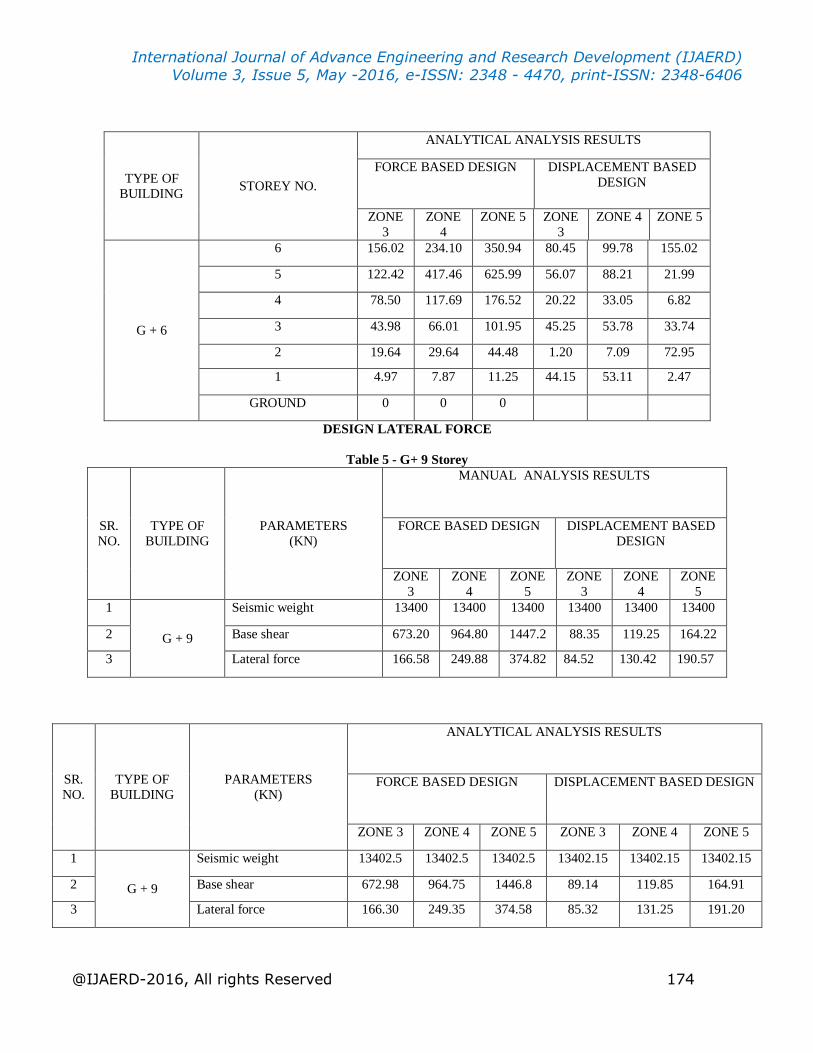
@IJAERD-2016, All rights Reserved 174
TYPE OF
BUILDING STOREY NO.
ANALYTICAL ANALYSIS RESULTS
FORCE BASED DESIGN DISPLACEMENT BASED
DESIGN
ZONE
3
ZONE
4
ZONE 5 ZONE
3
ZONE 4 ZONE 5
G + 6
6 156.02 234.10 350.94 80.45 99.78 155.02
5 122.42 417.46 625.99 56.07 88.21 21.99
4 78.50 117.69 176.52 20.22 33.05 6.82
3 43.98 66.01 101.95 45.25 53.78 33.74
2 19.64 29.64 44.48 1.20 7.09 72.95
1 4.97 7.87 11.25 44.15 53.11 2.47
GROUND 0 0 0
DESIGN LATERAL FORCE
Table 5 - G+ 9 Storey
SR.
NO.
TYPE OF
BUILDING
PARAMETERS
(KN)
MANUAL ANALYSIS RESULTS
FORCE BASED DESIGN DISPLACEMENT BASED
DESIGN
ZONE
3
ZONE
4
ZONE
5
ZONE
3
ZONE
4
ZONE
5
1
G + 9
Seismic weight 13400 13400 13400 13400 13400 13400
2 Base shear 673.20 964.80 1447.2 88.35 119.25 164.22
3 Lateral force 166.58 249.88 374.82 84.52 130.42 190.57
SR.
NO.
TYPE OF
BUILDING
PARAMETERS
(KN)
ANALYTICAL ANALYSIS RESULTS
FORCE BASED DESIGN DISPLACEMENT BASED DESIGN
ZONE 3 ZONE 4 ZONE 5 ZONE 3 ZONE 4 ZONE 5
1
G + 9
Seismic weight 13402.5 13402.5 13402.5 13402.15 13402.15 13402.15
2 Base shear 672.98 964.75 1446.8 89.14 119.85 164.91
3 Lateral force 166.30 249.35 374.58 85.32 131.25 191.20

International Journal of Advance Engineering and Research Development (IJAERD)
Volume 3, Issue 5, May -2016, e-ISSN: 2348 - 4470, print-ISSN: 2348-6406
@IJAERD-2016, All rights Reserved 175
TYPE OF
BUILDING STOREY NO.
MANUAL ANALYSIS RESULTS
FORCE BASED DESIGN DISPLACEMENT BASED
DESIGN
ZONE
3
ZONE 4 ZONE
5
ZONE
3
ZONE
4
ZONE
5
G + 9
9 166.58 249.88 374.82 88.35 119.25 164.22
8 315.80 473.71 710.57 148.92 199.65 210.54
7 460.28 645.44 968.17 220.65 205.97 225.27
6 544.53 771.84 1157.7 240.98 215.75 330.58
5 603.06 859.64 1289.4 258.35 250.59 378.70
4 640.36 915.59 1373.3 267.39 275.51 451.52
3 661.58 947.43 1420.6 275.54 287.28 479.89
2 670.90 961.43 1441.6 280.87 295.45 491.29
1 673.21 964.80 1447.1 282.30 297.88 495.27
GROUND 0 0 0 0 0 0
TYPE OF
BUILDING STOREY NO.
ANALYTICAL ANALYSIS RESULTS
FORCE BASED DESIGN DISPLACEMENT BASED
DESIGN
ZONE
3
ZONE
4
ZONE 5 ZONE 3 ZONE 4 ZONE 5
G + 9
9 166.90 250.04 374.95 88.98 120.01 164.69
8 315.98 473.99 710.75 149.58 200.12 211.44
7 460.56 645.74 968.28 221.11 206.87 226.16
6 460.45 771.97 1157.9 241.56 216.84 331.14
5 603.58 859.78 1289.6 259.01 251.91 379.19
4 640.49 915.98 1373.6 268.20 276.87 452.21
3 661.92 947.59 1420.8 276.29 288.97 480.41
2 671.05 961.79 1441.8 281.45 296.50 491.92
1 673.58 964.98 1447.6 283.25 298.54 496.09
GROUND 0 0 0 0 0 0

International Journal of Advance Engineering and Research Development (IJAERD)
Volume 3, Issue 5, May -2016, e-ISSN: 2348 - 4470, print-ISSN: 2348-6406
@IJAERD-2016, All rights Reserved 176
BASE SHEAR DISTRIBUTION
TYPE OF
BUILDING STOREY NO.
MANUAL ANALYSIS RESULTS
FORCE BASED DESIGN DISPLACEMENT BASED
DESIGN
ZONE
3
ZONE
4
ZONE
5
ZONE
3
ZONE
4
ZONE
5
G + 9
9 166.58 249.88 374.82 88.35 119.25 164.22
8 149.22 223.83 335.75 60.57 80.40 46.32
7 144.48 171.73 257.60 71.73 6.32 14.73
6 84.25 126.40 189.58 20.33 9.78 105.31
5 58.53 87.80 131.69 17.37 34.84 48.12
4 37.30 55.95 83.93 9.04 24.92 72.82
3 21.22 31.84 47.75 8.15 11.77 28.37
2 9.32 14.00 20.98 5.33 8.17 11.40
1 2.31 3.47 5.20 1.43 2.43 3.98
GROUND 0 0 0 0 0 0
TYPE OF
BUILDING STOREY NO.
ANALYTICAL ANALYSIS RESULTS
FORCE BASED DESIGN DISPLACEMENT BASED
DESIGN
ZONE
3
ZONE
4
ZONE 5 ZONE
3
ZONE 4 ZONE 5
G + 9
9 166.90 250.04 374.95 89.18 119.65 165.25
8 149.48 223.91 335.84 61.45 81.15 47.87
7 144.58 171.81 257.72 72.82 7.09 15.58
6 84.56 126.46 189.68 21.54 10.95 106.21
5 58.61 87.95 131.79 18.45 35.65 49.24
4 37.45 56.05 84.01 10.54 25.87 73.89
3 21.54 31.98 47.93 9.27 12.89 29.67
2 9.46 14.25 21.15 6.54 9.45 12.85
1 2.50 3.58 5.58 2.54 3.87 5.01
GROUND 0 0 0 0 0 0
DESIGN LATERAL FORCE
VII. REMARKS
The base shear of RC buildings designed with Displacement-Based Design has been compared with those designed with
Forced-Based Design method. Frame buildings for three different zones have been designed with Forced-Based Design
method. The same category of buildings has been designed with Displacement-Based Design for the criteria specified given
by those designed with Forced-Based Design method. Results have been presented for various zones. The base shear and
lateral forces for all the three zones have been evaluated. Results show that buildings designed with Forced-Based Design
method are more base shear and lateral force than designed with Displacement-Based Design.

International Journal of Advance Engineering and Research Development (IJAERD)
Volume 3, Issue 5, May -2016, e-ISSN: 2348 - 4470, print-ISSN: 2348-6406
@IJAERD-2016, All rights Reserved 177
REFERENCES
1. Displacement-Based Seismic Design of Structures by M. J. N. PRIESTLEY, G. M. CALVI, M.J. KOWALSKY.
2. Displacement based design of RC structures, J. P. Moehle, University of California at Berkeley, USA, Earthquake
Engineering, Tenth World Conference @ 1992
3. A Displacement-Based Analysis And Design Procedure For Structural Walls, H.G. Urrego and R.L. Bonett, The
14th World Conference on Earthquake Engineering October 12-17, 2008, Beijing, China
4. Comparison between the Direct Displacement Based Design and the Force Based Design Methods in Reinforced
Concrete Framed Structures, Adel ElAttar, AbdelHamd Zaghw and Ahmed Elansary, Istanbul
5. A Displacement-Based Seismic Design for Reinforced Concrete Structures, Abderrachid Boulaouad and Ahmed Amour, KSCE Journal of Civil Engineering (2011)
6. Displacement Based Seismic Design Methods, C. Hofmayer, C. Miller, Y. Wang, J. Costello
7. A Displacement based Design Method For Mediumrise Reinforced Concrete Walls, Hector Urrego, Ricardo L.
Bonett
8. Displacement–Based Seismic Design of Structures, G.M. Calvi, M.J.N. Priestley, and M.J.Kowalsky, North Carolina
State University, Raleigh, USA
9. Direct Displacement-Based Design: Use of Inelastic Design Spectra Versus Elastic Design Spectra, Anil K. Chopra,
M. EERI, and Rakesh K. Goel, M. EERI
10. Direct Displacement Based Design of a RC Frame – Case of Study, B. Massena, R. Bento, H. Degee, 2010
11. Seismic Evaluation of R/C Framed Building Using Shear Failure Model, Avadhoot Bhosale
12. Direct Displacement Based Design of Regular Concrete Frames in Compliance With Eurocode 8, Damir Dzakic,
Ivan Kraus, Dragan Moric 13. Design verification of a force- and displacement-based designed torsionally-unbalanced wall building, Sara
Martini, November, 2007
14. An economic comparison of Direct displacement based Design with IS-1893 Response Spectrum method for R.C.
Frame Buildings, Sunil S. Mayengbam, Choudhury.S
15. Comparison of Base Shear for Forced-Based Design Method and Direct Displacement-Based Design Method,
Alefiya T. Dohadwala, Rutvik K. Sheth, Dr. Indrajit N. Patel
16. Comparison of DDBD with FBD procedures for concentrically braced steel frame, J. Goggins & S. Salawdeh