Embed Size (px)
Citation preview
International Journal of Engineering Science Invention
ISSN (Online): 2319 – 6734, ISSN (Print): 2319 – 6726
www.ijesi.org Volume 3 Issue 4 || April 2014 || PP.41-54
www.ijesi.org 42 | Page
Comparison Between Wind And Seismic Load On Different
Types Of Structures 1,
Sanhik Kar Majumder, 2,
Prof. Priyabrata Guha 1,
M.Tech (Structural Engineering) Narula Institute of Technology 2,
Narula Institute of Technology Agarpara,Kol-109, W.B., India
ABSTRACT—It is very important for considering the effects of lateral loads from wind and earthquakes for
design of reinforced concrete structures,especially for high-rise buildings.Some cases the effect of earthquake is
found more critical than wind effect. It depends on some factors defined by codes. In this study the both effects
will be considered and compared according to the Code IS: 875(PART - 3) and IS:-1893-2002(PART-1) and
IS:875(PART-1 AND PART-2). A software program is developed to analyze the different types of structures
under wind pressure and earthquake effect considering all factors from the codes. Some recommendations are
suggested to develop different types of structures with respect to lateral loads.
KEYWORDS—Types of structures, Wind pressure,Seismic preassure,Dead Load,Live Load, Zone factor,
Load Combination, Importance factor.
I. INTRODUCTION My project involves Effect And Comparission Between Wind And Seismic Loads On Different
Types Of Building Structures [G + 7] using design software STAAD.ProV8i.
The advantages of this software are given below:
1. Easy to use, 2. Provisions of Indian standard codes 3. different natures of solving any types of problems, 4.
Perfection of accuracy.STAAD.ProV8i is more effective software for concrete, steel, aluminium and cold-
formed steel design, culverts, tunnels, bridges, timber, piles etc. than other softwares. Generally,
STAAD.ProV8i used to generate different types of models easily and also analysis and design is completed very
significantly. STAAD.Pro is a general purpose of structural analysis and design program with applications in the commercial
buildings, highway structures, industrial structures, chemical plant structures, dams, retaining walls, turbine
foundations and other embedded structures, etc. This program hence consists of the following facilities :
1.Beam and column members are represented by lines. Walls, slabs and panel type entities are represented using
triangular and quadrilateral finite elements. Solid blocks are represented using brick elements.
2. Analysis engines for performing linear elastic and pdelta analysis, finite element analysis, frequency
extraction, and dynamic response (spectrum, time history, steady state, etc.).
3. Design engines for code checking and optimization of steel, aluminum and timber members. Reinforcement
calculations for concrete beams, columns, slabs , Design of shear and moment connections for steel members.
4. Result verification and report generation tools for examining displacement diagrams, bending moment and
shear force diagrams .
II. LOADS CONSIDERED: 2.1 DEAD LOADS: Dead loads shall be calculated on basis of unit weights which shall be established taking
into consideration the materials specified for construction. This consist of walls, partitions, floors, roofs
including the weights of all other permanent structures. It may be calculated on the basis of unit weights of
materials given in IS 875(part -1).
2.2 IMPOSED LOADS: Imposed loads are produced from the weight of movable partitions of buildings,
uniformly distributed and concentrated loads. For structures carring live loads which induced impact and
vibration. Imposed loads shall be assumed in accordance with IS 875(part -2).
Comparison Between Wind And Seismic Load On Different Types Of Structures
www.ijesi.org 43 | Page
2.3 WIND LOAD: The IS 875(part -3) deals with wind loads to be considered when designing building ,
structures and components thereof.
Wind load depends upon wind speed and pressure -
a ) Basic wind speed (Vb):
IS 875(part-3), fig-1 gives basic wind speed map of India, as applicable to 10m height above mean ground level
for different zones of the country.
b) Design Wind Speed (Vz):
The basic wind speed (Vb) for any site shall be obtained and shall be modified to include the following effects
of design wind velocity at any height (Vz) for the chosen structure:
a) Risk level;
b) Terrain roughness, height and size of structure; and
c) Local topography.
It can be mathematically expressed as follows:
Vz = Vb * k1 * k2* k3
Vb = design wind speed at any height z in m/s;
K1= probability factor (risk coefficient)
K2 = terrain, height and structure size factor and
K3= topography factor
As per this study,
Vb = 50 m/s, K1=1, k2= 0.85, k3=1
c)Design Wind Pressure – The design wind pressure at any height above mean ground level shall be obtained
by the fallowing relationship between wind pressure and wind velocity : Pz =0.6 Vz²
Where,
Pz = Disign wind pressure in N/m² at height z , and
Vz = Design wind velocity in m/s at height z
2.4 SEISMIC LOAD: The seismic forces shall be calculated in accordance with IS 1893(part-1). This code
deals with assessment of seismic load on various structures and earthquake resistant of design of buildings.
Seismic load depends upon the following criteria:
a) Design horizontal acceleration co-efficient (Ah): It is a horizontal acceleration co-efficient that shall be
used for design of structures.
Ah = ZISa / 2Rg
Where, Z= Zone factor
I = Importance factor
R = Response reduction factor
Sa/ g = Avg. response acceleration co-efficient
b) Design Lateral Force:It is the horizontal seismic force prescribed by this standard, that shall be used to
design a structure.
c) Design Seismic Base Shear: The total design lateral force or design seismic base shear (Vb) along
shall be determined by the following expression: Vb = Ah W Where, Ah = horizontal acceleration spectrum W =
seismic weight of all the floors.
d) Fundamental natural period(T1): It is the first longest model time period of vibration.
e) Time History Method: Time history method of analysis shall be based on an appropriate ground motion
and shall be performed using accepted principles of dynamics.
f) Response Spectrum Method:- The representation of the maximum response of idealized single degree
fredom systems having certain period and damping during earthquake ground motion.
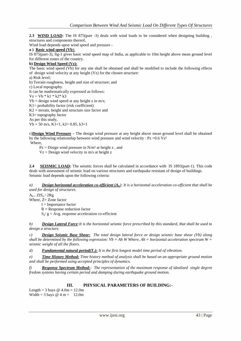
III. PHYSICAL PARAMETERS OF BUILDING:- Length = 3 bays @ 4.0m = 12.0m
Width = 3 bays @ 4 m = 12.0m
Comparison Between Wind And Seismic Load On Different Types Of Structures
www.ijesi.org 44 | Page
Height = 3m + 6 stories @ 3.0m = 21m (1.0m parapet being non- structural for seismic purposes, is not
considered of building frame height)
Live load on the floors is 1kN/m2 & Dead load on the roof
Is 2kN/m2
Grade of concrete and steel used:-
Used M30 concrete and Fe 415 steel.
All columns = 0.40 * 0.40 m ,
All beams = 0.3 * 0.3m ,
All slabs = 0.10 m thick
Plan of the G+7 storey building
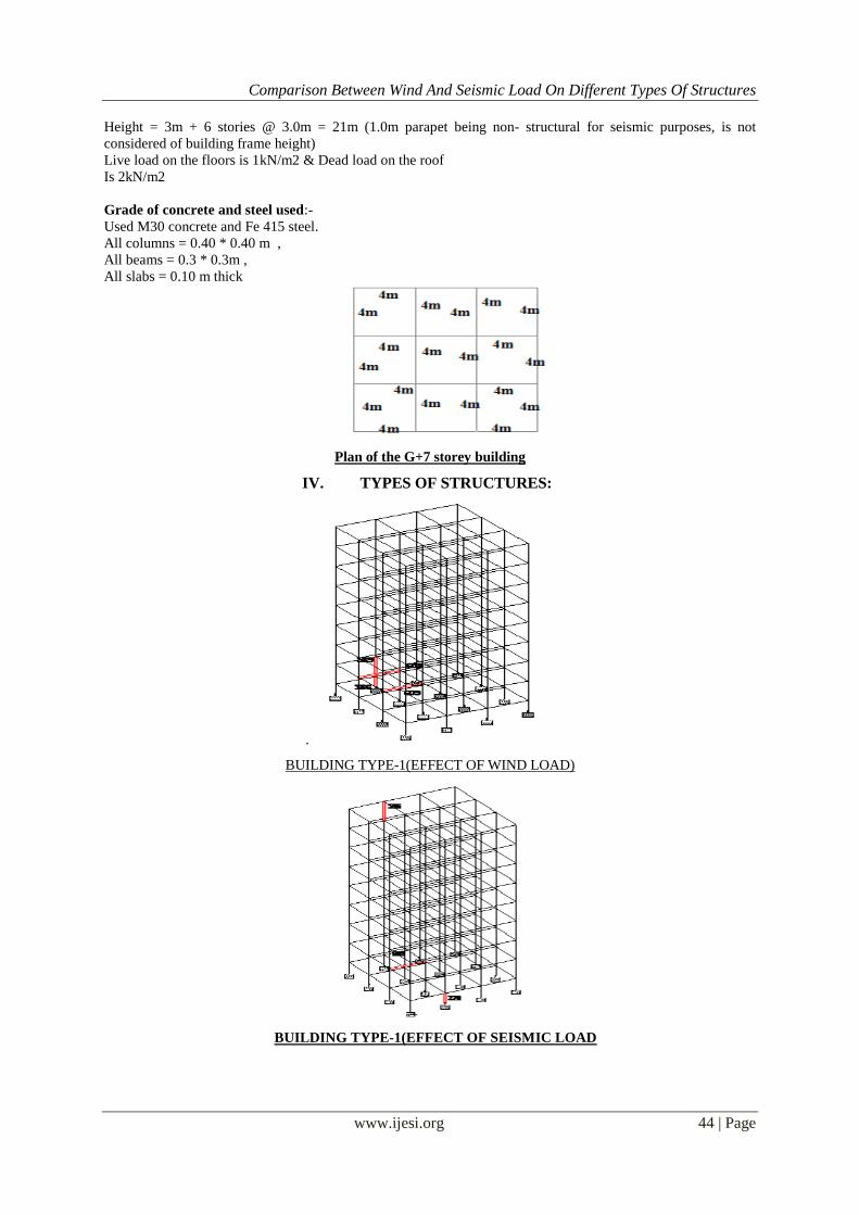
IV. TYPES OF STRUCTURES:
.
BUILDING TYPE-1(EFFECT OF WIND LOAD)
BUILDING TYPE-1(EFFECT OF SEISMIC LOAD
Comparison Between Wind And Seismic Load On Different Types Of Structures
www.ijesi.org 45 | Page
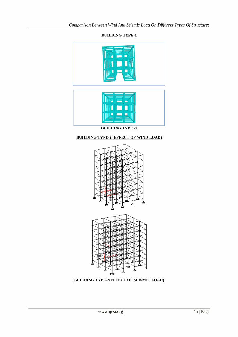
BUILDING TYPE-1
BUILDING TYPE -2
BUILDING TYPE-2 (EFFECT OF WIND LOAD)
BUILDING TYPE-2(EFFECT OF SEISMIC LOAD)

Comparison Between Wind And Seismic Load On Different Types Of Structures
www.ijesi.org 46 | Page
BUILDING TYPE-3(EFFECT OF WIND LOAD)
BUILDING TYPE -3(EFFECT OF SEISMIC LOAD)
BUILDINGTYPE-3
Comparison Between Wind And Seismic Load On Different Types Of Structures
www.ijesi.org 47 | Page
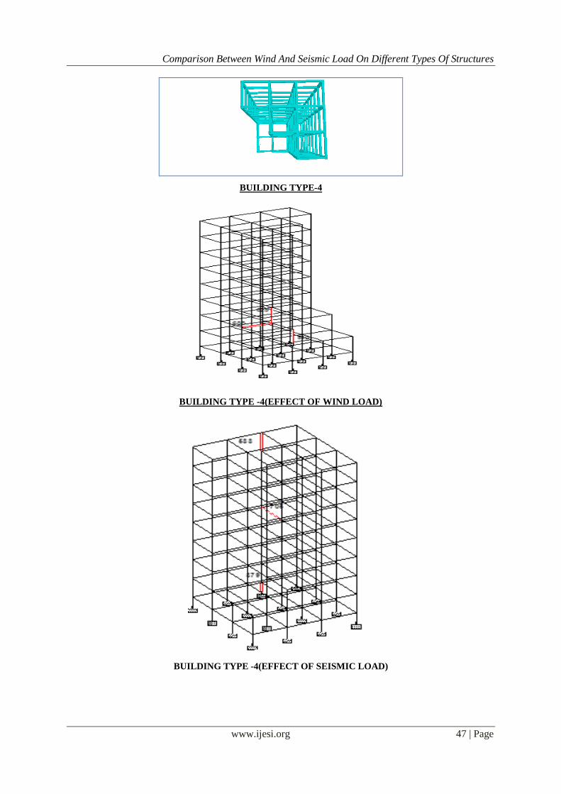
BUILDING TYPE-4
BUILDING TYPE -4(EFFECT OF WIND LOAD)
BUILDING TYPE -4(EFFECT OF SEISMIC LOAD)
Comparison Between Wind And Seismic Load On Different Types Of Structures
www.ijesi.org 48 | Page
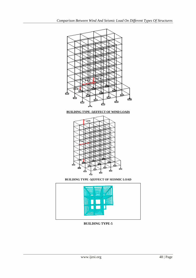
BUILDING TYPE -5(EFFECT OF WIND LOAD)
BUILDING TYPE -5(EFFECT OF SEISMIC LOAD
BUILDING TYPE-5
Comparison Between Wind And Seismic Load On Different Types Of Structures
www.ijesi.org 49 | Page
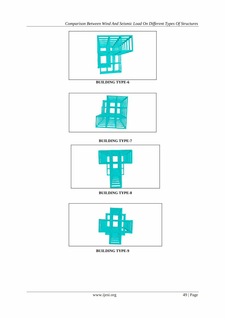
BUILDING TYPE-6
BUILDING TYPE-7
BUILDING TYPE-8
BUILDING TYPE-9
Comparison Between Wind And Seismic Load On Different Types Of Structures
www.ijesi.org 50 | Page
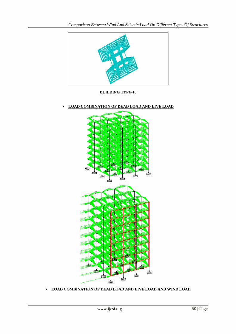
BUILDING TYPE-10
LOAD COMBINATION OF DEAD LOAD AND LIVE LOAD
LOAD COMBINATION OF DEAD LOAD AND LIVE LOAD AND WIND LOAD
Comparison Between Wind And Seismic Load On Different Types Of Structures
www.ijesi.org 51 | Page
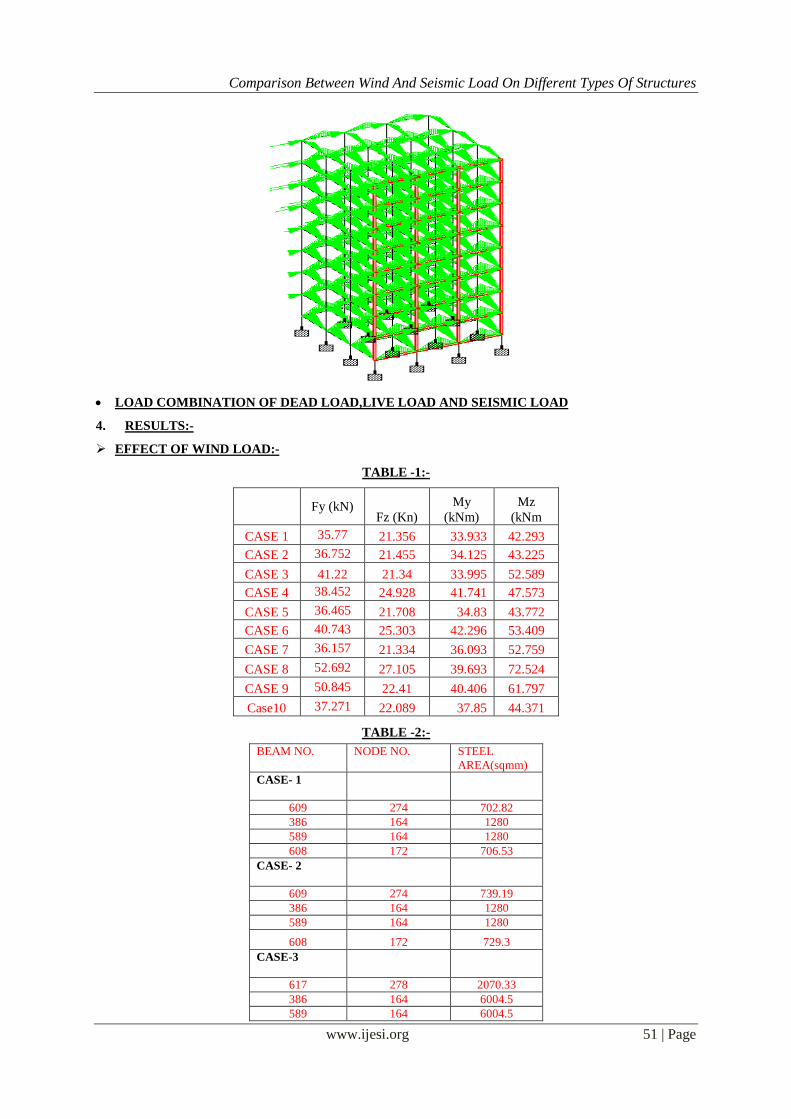
LOAD COMBINATION OF DEAD LOAD,LIVE LOAD AND SEISMIC LOAD
4. RESULTS:-
EFFECT OF WIND LOAD:-
TABLE -1:-
Fy (kN)
Fz (Kn)
My
(kNm)
Mz
(kNm
CASE 1 35.77 21.356 33.933 42.293
CASE 2 36.752 21.455 34.125 43.225
CASE 3 41.22 21.34 33.995 52.589
CASE 4 38.452 24.928 41.741 47.573
CASE 5 36.465 21.708 34.83 43.772
CASE 6 40.743 25.303 42.296 53.409
CASE 7 36.157 21.334 36.093 52.759
CASE 8 52.692 27.105 39.693 72.524
CASE 9 50.845 22.41 40.406 61.797
Case10 37.271 22.089 37.85 44.371
TABLE -2:-
BEAM NO. NODE NO. STEEL
AREA(sqmm)
CASE- 1
609 274 702.82
386 164 1280
589 164 1280
608 172 706.53
CASE- 2
609 274 739.19
386 164 1280
589 164 1280
608 172 729.3
CASE-3
617 278 2070.33
386 164 6004.5
589 164 6004.5
Comparison Between Wind And Seismic Load On Different Types Of Structures
www.ijesi.org 52 | Page
617 278 2070.33
CASE- 4
688 194 823.77
825 276 1280
510 172 1280
688 194 823.77
CASE-5
617 185 738.72
386 164 1280
581 157 1280
617 185 738.72
CASE- 6
705 217 982.64
817 279 1280
567 191 1280
705 283 982.64
CASE- 7
617 185 716.8
379 157 1280
530 234 1280
467 234 988.05
CASE- 8
681 271 864.54
845 303 1280
814 275 1280
410 176 882.56
CASE-9
729 253 864.54
502 171 2400
502 183 2400
808 297 864.54
CASE- 10
689 275 757.61
814 271 1280
813 267 1280
680 182 760.33
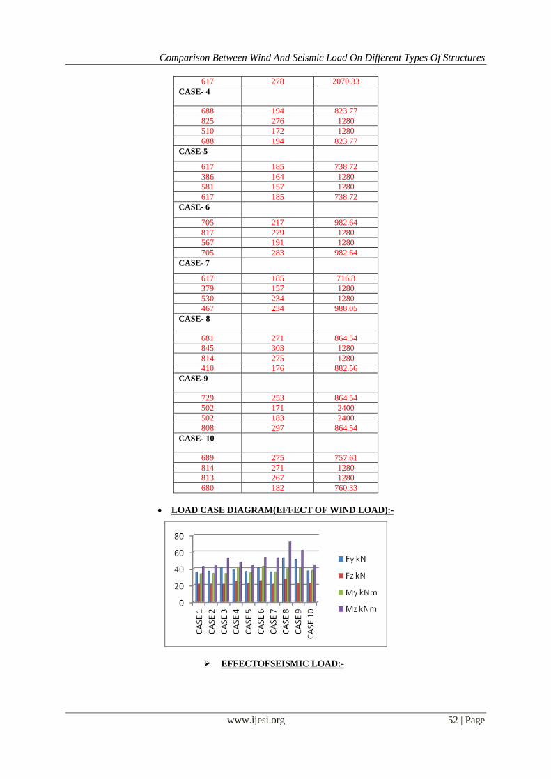
LOAD CASE DIAGRAM(EFFECT OF WIND LOAD):-
EFFECTOFSEISMIC LOAD:-

Comparison Between Wind And Seismic Load On Different Types Of Structures
www.ijesi.org 53 | Page
TABLE:- 1 Fy kN Fz kN My kNm Mz kNm
CASE 1 26.412 9.137 13.857 23.119
CASE 2 31.118 14.01 20.735 32.421
CASE 3 555.49 467.187 825.135 990.137
CASE 4 27.116 10.584 14.684 24.677
CASE 5 27.138 -10.714 15.039 24.74
CASE 6 27.569 10.209 17.707 25.208
CASE 7 27.665 11.725 27.001 43.718
CASE 8 38.197 11.596 16.015 35.144
CASE 9 42.054 17.371 33.613 53.221
CASE 10 27.087 10.529 13.455 24.321
TABLE :-2 BEAM NO. NODE NO. STEEL AREA(sqmm)
CASE- 1
609 274 702.82
328 30 1280
596 266 1280
609 274 702.82
CASE -2
617 278 736.32
386 164 1280
589 164 1280
696 206 638.48
CASE- 3
822 304 4736
CASE -4
705 217 648.3
379 157 1280
588 265 1280
705 217 648.3
CASE 5
632 208 584.37
386 164 1280
596 266 1280
632 208 584.37
CASE- 6
705 283 982.64
386 164 1280
534 187 1280
705 283 982.64
CASE - 7
633 209 604.9
531 234 1280
530 234 1280
467 234 988.05
CASE- 8
689 275 864.54
386 164 1280
816 283 1280
462 219 864.54
CASE- 9
729 253 864.54
866 253 2400
866 253 2400
808 297 864.54
CASE- 10
689 275 757.61
386 164 1280
589 164 1280
689 275 757.61
Comparison Between Wind And Seismic Load On Different Types Of Structures
www.ijesi.org 54 | Page
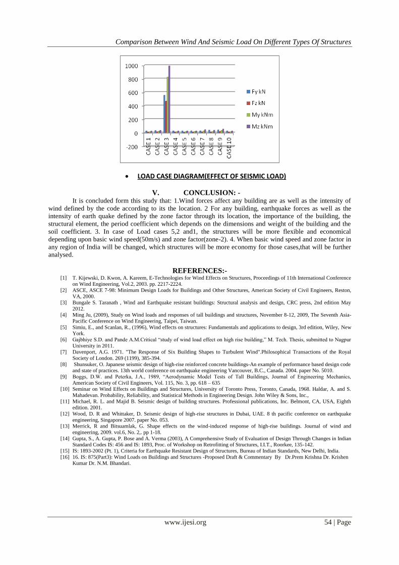
LOAD CASE DIAGRAM(EFFECT OF SEISMIC LOAD)
V. CONCLUSION: - It is concluded form this study that: 1.Wind forces affect any building are as well as the intensity of
wind defined by the code according to its the location. 2 For any building, earthquake forces as well as the
intensity of earth quake defined by the zone factor through its location, the importance of the building, the
structural element, the period coefficient which depends on the dimensions and weight of the building and the
soil coefficient. 3. In case of Load cases 5,2 and1, the structures will be more flexible and economical
depending upon basic wind speed(50m/s) and zone factor(zone-2). 4. When basic wind speed and zone factor in
any region of India will be changed, which structures will be more economy for those cases,that will be further
analysed.
REFERENCES:- [1] T. Kijewski, D. Kwon, A. Kareem, E-Technologies for Wind Effects on Structures, Proceedings of 11th International Conference
on Wind Engineering, Vol.2, 2003. pp. 2217-2224.
[2] ASCE, ASCE 7-98: Minimum Design Loads for Buildings and Other Structures, American Society of Civil Engineers, Reston,
VA, 2000. [3] Bungale S. Taranath , Wind and Earthquake resistant buildings: Structural analysis and design, CRC press, 2nd edition May
2012. [4] Ming Ju, (2009), Study on Wind loads and responses of tall buildings and structures, November 8-12, 2009, The Seventh Asia-
Pacific Conference on Wind Engineering, Taipei, Taiwan.
[5] Simiu, E., and Scanlan, R., (1996), Wind effects on structures: Fundamentals and applications to design, 3rd edition, Wiley, New York.
[6] Gajbhiye S.D. and Pande A.M.Critical “study of wind load effect on high rise building,” M. Tech. Thesis, submitted to Nagpur
University in 2011. [7] Davenport, A.G. 1971. "The Response of Six Building Shapes to Turbulent Wind".Philosophical Transactions of the Royal
Society of London. 269 (1199), 385-394.
[8] Shunsuker, O. Japanese seismic design of high-rise reinforced concrete buildings-An example of performance based design code and state of practices. 13th world conference on earthquake engineering Vancouver, B.C., Canada. 2004. paper No. 5010.
[9] Boggs, D.W. and Peterka, J.A., 1989, “Aerodynamic Model Tests of Tall Buildings, Journal of Engineering Mechanics,
American Society of Civil Engineers, Vol. 115, No. 3, pp. 618 – 635 [10] Seminar on Wind Effects on Buildings and Structures, University of Toronto Press, Toronto, Canada, 1968. Haldar, A. and S.
Mahadevan. Probability, Reliability, and Statistical Methods in Engineering Design. John Wiley & Sons, Inc.,
[11] Michael, R. L. and Majid B. Seismic design of building structures. Professional publications, Inc. Belmont, CA, USA, Eighth
edition. 2001.
[12] Wood, D. R and Whittaker, D. Seismic design of high-rise structures in Dubai, UAE. 8 th pacific conference on earthquake
engineering, Singapore 2007. paper No. 053. [13] Merrick, R and Bitsuamlak, G. Shape effects on the wind-induced response of high-rise buildings. Journal of wind and
engineering, 2009. vol.6, No. 2,. pp 1-18.
[14] Gupta, S., A. Gupta, P. Bose and A. Verma (2003), A Comprehensive Study of Evaluation of Design Through Changes in Indian Standard Codes IS: 456 and IS: 1893, Proc. of Workshop on Retrofitting of Structures, I.I.T., Roorkee, 135-142.
[15] IS: 1893-2002 (Pt. 1), Criteria for Earthquake Resistant Design of Structures, Bureau of Indian Standards, New Delhi, India.
[16] 16. IS: 875(Part3): Wind Loads on Buildings and Structures -Proposed Draft & Commentary By Dr.Prem Krishna Dr. Krishen Kumar Dr. N.M. Bhandari.