Embed Size (px)
Citation preview
COMPARATOR
Introduction
Comparators are one form of linear measurement device.
It is quick and more convenient for checking larger number of identical dimensions.
Comparators normally will not show the actual dimensions of the work piece. They
will show only the deviation in size.
This cannot be used as an absolute measuring device but can only compare two
dimensions.
Principle of comparator
The general principle of comparator is to indicate the difference in size between the
standard and work being measured by means of some pointer on the scale with
sufficient magnification.
Need for a comparator
A comparator is used in mass production to inspect the components to close tolerance
with high degree of precision and speed
Use of line standards such as vernier caliper and micrometer required considerable
skill
Many dimensions can be checked in a very short time.
Uses of comparator
To check the components and newly purchased gauges.
As laboratory standards to set working or inspection gauges.
As a final inspection gauge.
Essential Characteristics of Comparator:
1. Robust design and construction:
The design and construction of the instrument should be robust so that it can
withstand the effects of ordinary uses without affecting its measuring accuracy.
2. Linear characteristics of scale:
Recording or measuring scale should be linear and uniform (straight line
characteristic) and its indications should be clear.
3. High magnification:
The magnification of the instrument should be such that a smallest deviation in size of
component can be easily detected.
4. Quick in results:
The indicating system should be such that the readings are obtained least possible
time.
5. Versatility:
Instrument should be so designed that it can be used for wide range of measurement.
1
6. Measuring plunger should have the hardened steel, or diamond contact to minimise wear
and contact pressure should be low and uniform.
7. The pointer should come rapidly to rest and should be free from oscillations.
8. System should be free from back lash and unnecessary friction and it should have a
minimum inertia.
9. Indicator should be provided with maximum compensation for temperature effects.
10. Indicator should return to its initial zero position every time.
Working Principle of Mechanical comparators:
The magnification of plunger movement can be obtained mechanical means such as
levers, gear and pinion arrangement or other mechanical means.
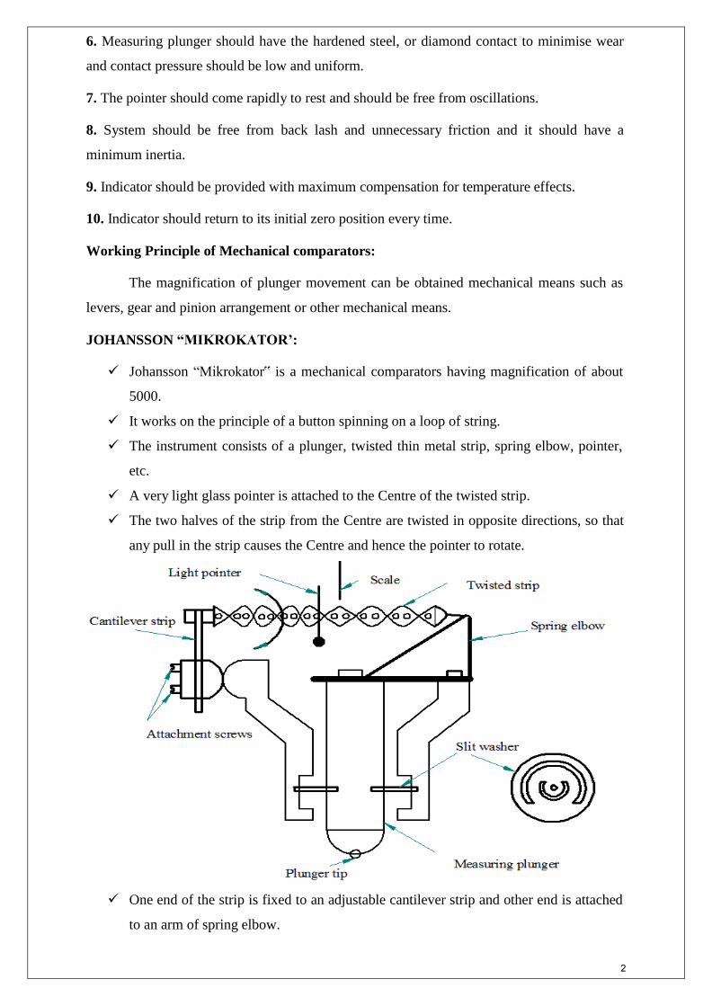
JOHANSSON “MIKROKATOR’:
Johansson “Mikrokator‟ is a mechanical comparators having magnification of about
5000.
It works on the principle of a button spinning on a loop of string.
The instrument consists of a plunger, twisted thin metal strip, spring elbow, pointer,
etc.
A very light glass pointer is attached to the Centre of the twisted strip.
The two halves of the strip from the Centre are twisted in opposite directions, so that
any pull in the strip causes the Centre and hence the pointer to rotate.
One end of the strip is fixed to an adjustable cantilever strip and other end is attached
to an arm of spring elbow.
2
The measuring plunger is mounted on a flexible diaphragm. Its inner end is attached
to the other arm of spring elbow.
Thus the vertical movement of the plunger transmitted to the metal strip through the
elbow.
Any vertical movements of the plunger make it to twist or untwist.
This will cause the pointer to rotate by an amount proportional to the change in the
length of the strip
Magnification of the instrument depends upon the length, width and number of twists
of the twisted strip.
It can varied by changing the length of the strip with screws provided on adjustable
cantilever strip.
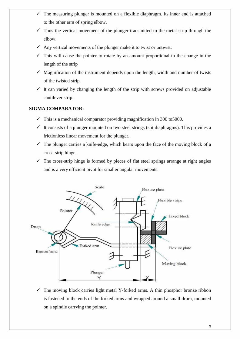
SIGMA COMPARATOR:
This is a mechanical comparator providing magnification in 300 to5000.
It consists of a plunger mounted on two steel strings (slit diaphragms). This provides a
frictionless linear movement for the plunger.
The plunger carries a knife-edge, which bears upon the face of the moving block of a
cross-strip hinge.
The cross-strip hinge is formed by pieces of flat steel springs arrange at right angles
and is a very efficient pivot for smaller angular movements.
The moving block carries light metal Y-forked arms. A thin phosphor bronze ribbon
is fastened to the ends of the forked arms and wrapped around a small drum, mounted
on a spindle carrying the pointer.
3
Any vertical displacement of measuring plunger and hence that of the knife edge
makes the moving block of the cross-strip hinge to pivot.
This causes the rotation of the Y-arms. The metallic band attached to the arms makes
the driving drum and hence the pointer to rotate.
The ratio of the effective length (L) of the arm and the distance (X) of the knife edge
from the pivot gives the first stage magnification
The ratio of pointer length (R) and radius r of the driving drum gives second stage
magnification of the instrument.
Total magnification of the instrument is thus (L/X× R/r).
The magnification of the instrument can be varied by changing the distance (X) of
knife-edge by tightening or slackening of the adjusting screws.
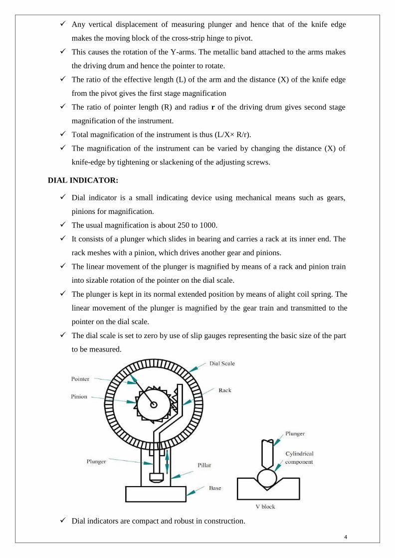
DIAL INDICATOR:
Dial indicator is a small indicating device using mechanical means such as gears,
pinions for magnification.
The usual magnification is about 250 to 1000.
It consists of a plunger which slides in bearing and carries a rack at its inner end. The
rack meshes with a pinion, which drives another gear and pinions.
The linear movement of the plunger is magnified by means of a rack and pinion train
into sizable rotation of the pointer on the dial scale.
The plunger is kept in its normal extended position by means of alight coil spring. The
linear movement of the plunger is magnified by the gear train and transmitted to the
pointer on the dial scale.
The dial scale is set to zero by use of slip gauges representing the basic size of the part
to be measured.
Dial indicators are compact and robust in construction.
4
They are portable, easy to handle and can be set very quickly.
This type of comparator can be used with various attachments so that it may be used
for larger number of works.
They are used for inspection of small precision machined parts testing alignment,
roundness, parallelism of work pieces, etc.
Advantages of Mechanical Comparators
They are cheaper compared to other amplifying devices.
Do not required electricity or air and such the variations in the outside sources do not
affect the accuracy.
They have a linear scale robust and easy to handle.
It is suitable for ordinary workshop and also easily portable.
Disadvantages of Mechanical Comparators
They have more moving linkages, due to which friction is more and accuracy is low.
Any wear, dimensional faults in the mechanical devices used will also be magnified.
The range of the instrument is limited, because the pointer moves over a fixed scale
OPTICAL COMPARATOR
Introduction
There are no pure optical comparators but the instruments classed as optical
comparators obtain large magnification in these instruments contributes principles though
mechanical magnification
All optical comparators are capable of giving high degree of measuring precision.
Working principle of Optical comparators:
Operating principle of this type, of comparator is based on the laws of light reflection
and refraction. Magnification system depends on the tilting of a mirror, deflects a beam of
light, thus providing an optical lever.
Principle of optical lever
If a beam of light AC is directed on to a mirror as shown in figure, it will be reflected
onto the screen at O as a dot.
The angle Ɵ at which the beam strikes the mirror is equal to the angle Ɵ at which the
beam is reflected from mirror.
When the plunger moves upwards vertically, causing the mirror to tilt by an angle „α‟
as shown in figure.
5
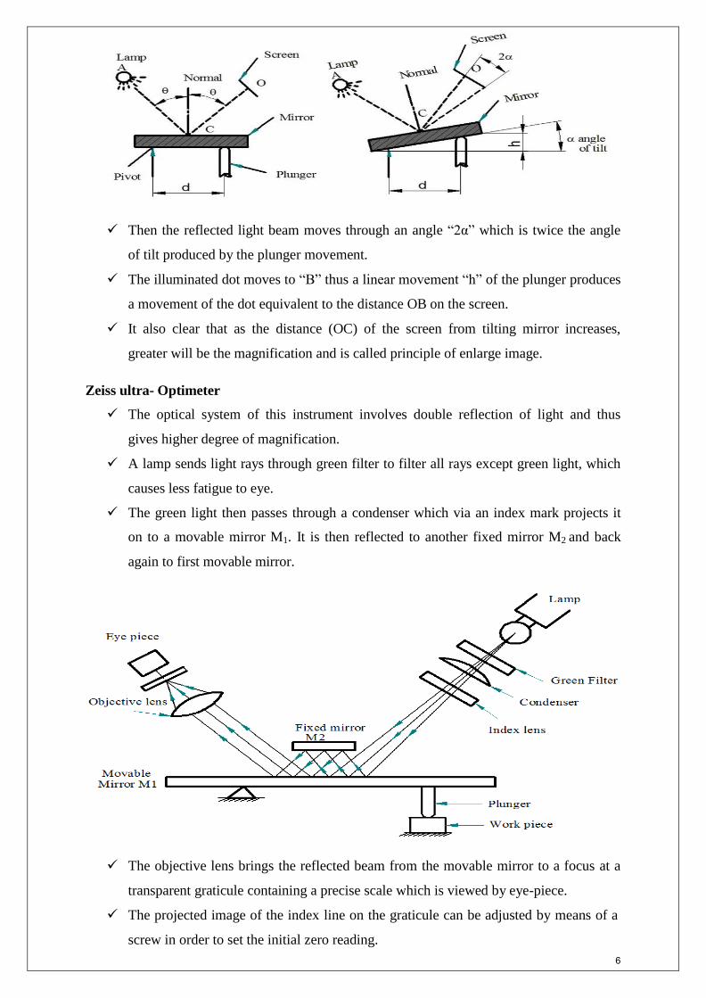
Then the reflected light beam moves through an angle “2α” which is twice the angle
of tilt produced by the plunger movement.
The illuminated dot moves to “B” thus a linear movement “h” of the plunger produces
a movement of the dot equivalent to the distance OB on the screen.
It also clear that as the distance (OC) of the screen from tilting mirror increases,
greater will be the magnification and is called principle of enlarge image.
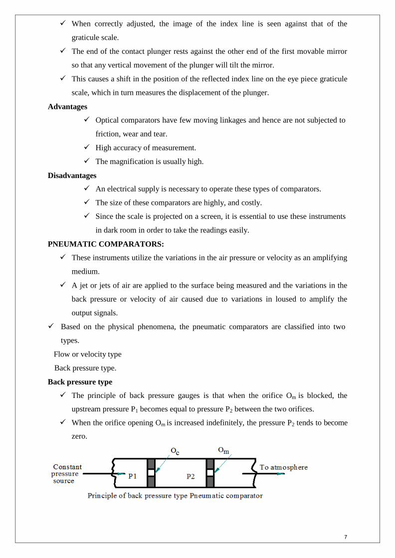
Zeiss ultra- Optimeter
The optical system of this instrument involves double reflection of light and thus
gives higher degree of magnification.
A lamp sends light rays through green filter to filter all rays except green light, which
causes less fatigue to eye.
The green light then passes through a condenser which via an index mark projects it
on to a movable mirror M1. It is then reflected to another fixed mirror M2 and back
again to first movable mirror.
The objective lens brings the reflected beam from the movable mirror to a focus at a
transparent graticule containing a precise scale which is viewed by eye-piece.
The projected image of the index line on the graticule can be adjusted by means of a
screw in order to set the initial zero reading.
6
When correctly adjusted, the image of the index line is seen against that of the
graticule scale.
The end of the contact plunger rests against the other end of the first movable mirror
so that any vertical movement of the plunger will tilt the mirror.
This causes a shift in the position of the reflected index line on the eye piece graticule
scale, which in turn measures the displacement of the plunger.
Advantages
Optical comparators have few moving linkages and hence are not subjected to
friction, wear and tear.
High accuracy of measurement.
The magnification is usually high.
Disadvantages
An electrical supply is necessary to operate these types of comparators.
The size of these comparators are highly, and costly.
Since the scale is projected on a screen, it is essential to use these instruments
in dark room in order to take the readings easily.
PNEUMATIC COMPARATORS:
These instruments utilize the variations in the air pressure or velocity as an amplifying
medium.
A jet or jets of air are applied to the surface being measured and the variations in the
back pressure or velocity of air caused due to variations in loused to amplify the
output signals.
Based on the physical phenomena, the pneumatic comparators are classified into two
types.
Flow or velocity type
Back pressure type.
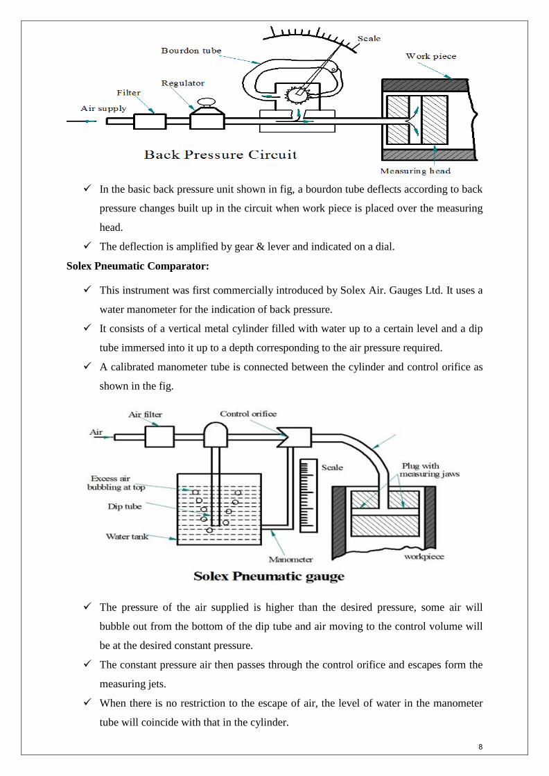
Back pressure type
The principle of back pressure gauges is that when the orifice Om is blocked, the
upstream pressure P1 becomes equal to pressure P2 between the two orifices.
When the orifice opening Om is increased indefinitely, the pressure P2 tends to become
zero.
7
In the basic back pressure unit shown in fig, a bourdon tube deflects according to back
pressure changes built up in the circuit when work piece is placed over the measuring
head.
The deflection is amplified by gear & lever and indicated on a dial.
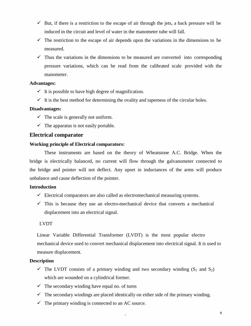
Solex Pneumatic Comparator:
This instrument was first commercially introduced by Solex Air. Gauges Ltd. It uses a
water manometer for the indication of back pressure.
It consists of a vertical metal cylinder filled with water up to a certain level and a dip
tube immersed into it up to a depth corresponding to the air pressure required.
A calibrated manometer tube is connected between the cylinder and control orifice as
shown in the fig.
The pressure of the air supplied is higher than the desired pressure, some air will
bubble out from the bottom of the dip tube and air moving to the control volume will
be at the desired constant pressure.
The constant pressure air then passes through the control orifice and escapes form the
measuring jets.
When there is no restriction to the escape of air, the level of water in the manometer
tube will coincide with that in the cylinder.
8
1
But, if there is a restriction to the escape of air through the jets, a back pressure will be
induced in the circuit and level of water in the manometer tube will fall.
The restriction to the escape of air depends upon the variations in the dimensions to be
measured.
Thus the variations in the dimensions to be measured are converted into corresponding
pressure variations, which can be read from the calibrated scale provided with the
manometer.
Advantages:
It is possible to have high degree of magnification.
It is the best method for determining the ovality and taperness of the circular holes.
Disadvantages:
The scale is generally not uniform.
The apparatus is not easily portable.
Electrical comparator
Working principle of Electrical comparators:
These instruments are based on the theory of Wheatstone A.C. Bridge. When the
bridge is electrically balanced, no current will flow through the galvanometer connected to
the bridge and pointer will not deflect. Any upset in inductances of the arms will produce
unbalance and cause deflection of the pointer.
Introduction
Electrical comparators are also called as electromechanical measuring systems.
This is because they use an electro-mechanical device that converts a mechanical
displacement into an electrical signal.
LVDT
Linear Variable Differential Transformer (LVDT) is the most popular electro
mechanical device used to convert mechanical displacement into electrical signal. It is used to
measure displacement.
Description
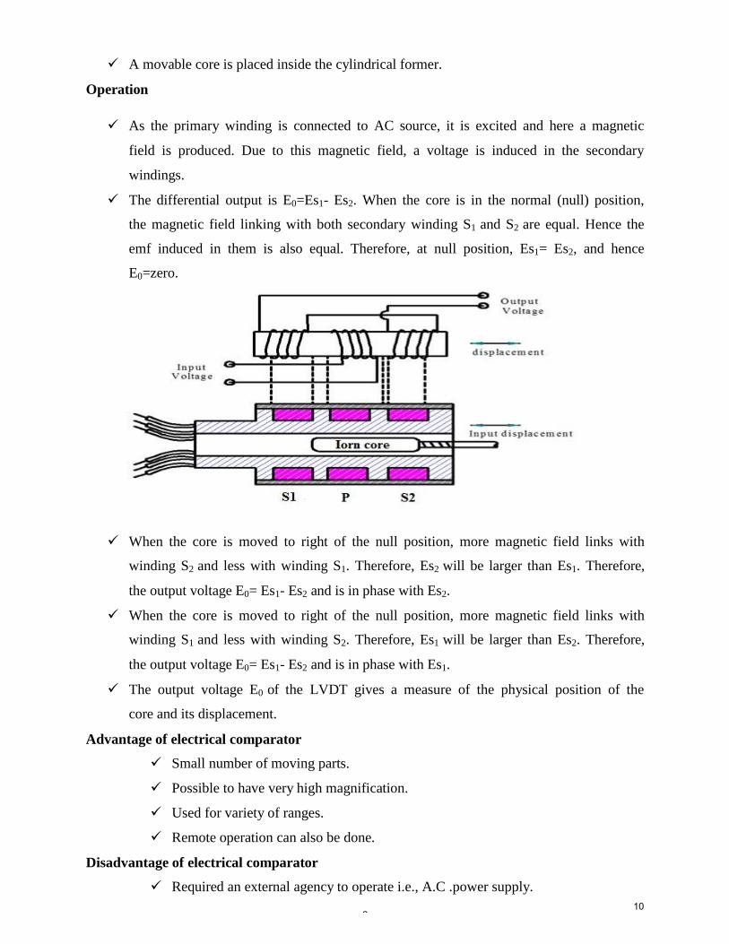
The LVDT consists of a primary winding and two secondary winding (S1 and S2)
which are wounded on a cylindrical former.
The secondary winding have equal no. of turns
The secondary windings are placed identically on either side of the primary winding.
The primary winding is connected to an AC source.
9
2
A movable core is placed inside the cylindrical former.
Operation
As the primary winding is connected to AC source, it is excited and here a magnetic
field is produced. Due to this magnetic field, a voltage is induced in the secondary
windings.
The differential output is E0=Es1- Es2. When the core is in the normal (null) position,
the magnetic field linking with both secondary winding S1 and S2 are equal. Hence the
emf induced in them is also equal. Therefore, at null position, Es1= Es2, and hence
E0=zero.
When the core is moved to right of the null position, more magnetic field links with
winding S2 and less with winding S1. Therefore, Es2 will be larger than Es1. Therefore,
the output voltage E0= Es1- Es2 and is in phase with Es2.
When the core is moved to right of the null position, more magnetic field links with
winding S1 and less with winding S2. Therefore, Es1 will be larger than Es2. Therefore,
the output voltage E0= Es1- Es2 and is in phase with Es1.
The output voltage E0 of the LVDT gives a measure of the physical position of the
core and its displacement.
Advantage of electrical comparator
Small number of moving parts.
Possible to have very high magnification.
Used for variety of ranges.
Remote operation can also be done.
Disadvantage of electrical comparator
Required an external agency to operate i.e., A.C .power supply.
10

3
Heating coils may cause zero drift.
More expansive than mechanical comparator.
11
4
INTERFEROMETER
Principle of interferometry
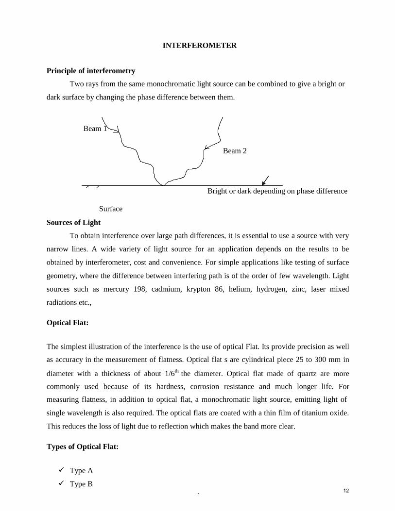
Two rays from the same monochromatic light source can be combined to give a bright or
dark surface by changing the phase difference between them.
Beam 1
Surface
Sources of Light
Beam 2
Bright or dark depending on phase difference
To obtain interference over large path differences, it is essential to use a source with very
narrow lines. A wide variety of light source for an application depends on the results to be
obtained by interferometer, cost and convenience. For simple applications like testing of surface
geometry, where the difference between interfering path is of the order of few wavelength. Light
sources such as mercury 198, cadmium, krypton 86, helium, hydrogen, zinc, laser mixed
radiations etc.,
Optical Flat:
The simplest illustration of the interference is the use of optical Flat. Its provide precision as well
as accuracy in the measurement of flatness. Optical flat s are cylindrical piece 25 to 300 mm in
diameter with a thickness of about 1/6th
the diameter. Optical flat made of quartz are more
commonly used because of its hardness, corrosion resistance and much longer life. For
measuring flatness, in addition to optical flat, a monochromatic light source, emitting light of
single wavelength is also required. The optical flats are coated with a thin film of titanium oxide.
This reduces the loss of light due to reflection which makes the band more clear.
Types of Optical Flat:
Type A
Type B 12
5
Type A:
It has single flat working surface. It is used for testing flatness of precision measuring
surfaces of flats, slip gauges, measuring tables.
Type B:
It has both working surfaces flat and parallel to each other. It is used for test measuring
surfaces of micrometer, measuring anvils etc.
Working of Optical Flat:
When an optical flat is placed on work piece surface it will not form an intimate contact, but will
be at slight inclination to the surface, forming at air wedge between the surfaces.
If optical flat is now illuminated by monochromatic source of light, interference fringes will be
observed. These are produced by the interference of light rays reflected from the bottom face of
the optical flat and top face of the work piece being tested through the layers of air.
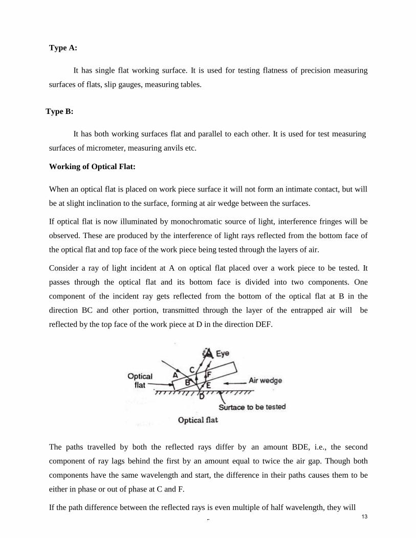
Consider a ray of light incident at A on optical flat placed over a work piece to be tested. It
passes through the optical flat and its bottom face is divided into two components. One
component of the incident ray gets reflected from the bottom of the optical flat at B in the
direction BC and other portion, transmitted through the layer of the entrapped air will be
reflected by the top face of the work piece at D in the direction DEF.
The paths travelled by both the reflected rays differ by an amount BDE, i.e., the second
component of ray lags behind the first by an amount equal to twice the air gap. Though both
components have the same wavelength and start, the difference in their paths causes them to be
either in phase or out of phase at C and F.
If the path difference between the reflected rays is even multiple of half wavelength, they will13
6
out of phase and dark band will be observed. If the path difference between the reflected
rays is odd multiple of half wavelength, they will be in phase and bright band will be
observed.
Limitation of optical Flat:
The fringe pattern is not viewed from directly.
It is difficult to control the lay of the optical Flat.
Interferometers
Interferometers are optical instrument used for measuring flatness and determining the
length of the specimen.
The wavelength of light wave is used as measuring unit.
It is based on the interference principle.
Michelson Interferometer
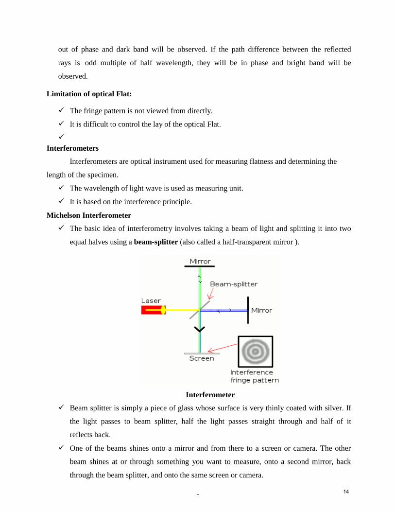
The basic idea of interferometry involves taking a beam of light and splitting it into two
equal halves using a beam-splitter (also called a half-transparent mirror ).
Interferometer
Beam splitter is simply a piece of glass whose surface is very thinly coated with silver. If
the light passes to beam splitter, half the light passes straight through and half of it
reflects back.
One of the beams shines onto a mirror and from there to a screen or camera. The other
beam shines at or through something you want to measure, onto a second mirror, back
through the beam splitter, and onto the same screen or camera.
14
7
This second beam travels an extra distance (or in some other slightly different way) to the
first beam, so it gets slightly out of step (out of phase).
When the two light beams meet up at the screen or camera, they overlap and interfere,
and the phase difference between them creates a pattern of light and dark areas (in other
words, a set of interference fringes).
The light areas are places where the two beams have added together (constructively) and
become brighter; the dark areas are places where the beams have subtracted from one
another (destructively). The exact pattern of interference depends on the different way or
the extra distance that one of the beams has travelled.
By inspecting and measuring the fringes, flatness is calculated with great accuracy.
Flatness Interferometer
• This instrument, as the name suggests, is mainly used for checking the flatness of flat
surfaces.
• This interferometer was designed by National Physical Laboratory and is commercially
manufactured by Hilger and Watts Ltd.
• The flatness of any surface is judged by comparing with an optically flat surface which is
generally the base plate of the instrument.
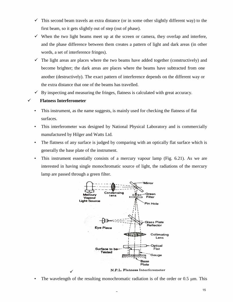
• This instrument essentially consists of a mercury vapour lamp (Fig. 6.21). As we are
interested in having single monochromatic source of light, the radiations of the mercury
lamp are passed through a green filter.
• The wavelength of the resulting monochromatic radiation is of the order or 0.5 μm. This
15
8
radiation is then brought to focus on pinhole in order to obtain an intense point source of
light.
• A mirror is used in order to deflect the light beam through 90°. The pinhole is placed in
the focal plane of a collimating lens, thus the radiations out of the lens will be parallel
beam of light.
• This beam is directed on the gauge to be tested which is wrung on the base plate, via an
optical flat so that fringes formed are viewed directly above by means of a thick glass
plate semi-reflector set at 45° to the optical axis.
• As the optical flat is placed above it in a little tilted position, interference fringes are
formed; one between rays reflected from the under surface of the optical flat and those
reflected from the surface of the gauge, and the other between rays reflected from the
under surface of the optical flat and those reflected from the base plate.
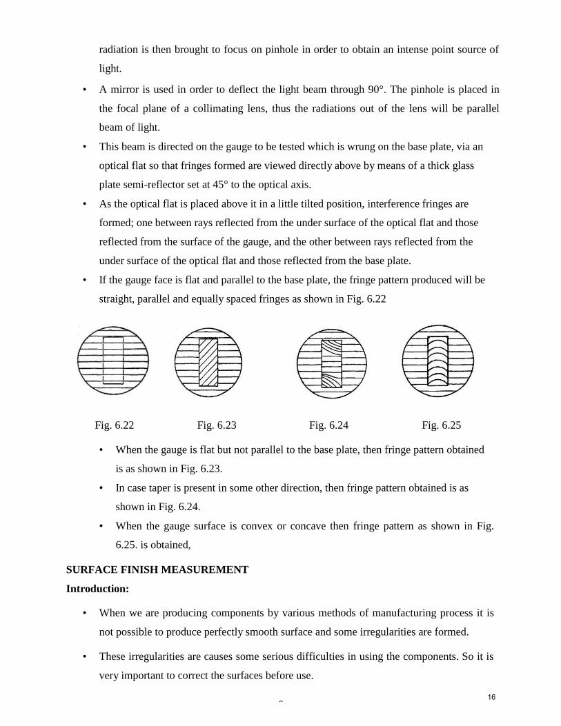
• If the gauge face is flat and parallel to the base plate, the fringe pattern produced will be
straight, parallel and equally spaced fringes as shown in Fig. 6.22
Fig. 6.22 Fig. 6.23 Fig. 6.24 Fig. 6.25
• When the gauge is flat but not parallel to the base plate, then fringe pattern obtained
is as shown in Fig. 6.23.
• In case taper is present in some other direction, then fringe pattern obtained is as
shown in Fig. 6.24.
• When the gauge surface is convex or concave then fringe pattern as shown in Fig.
6.25. is obtained,
SURFACE FINISH MEASUREMENT
Introduction:
• When we are producing components by various methods of manufacturing process it is
not possible to produce perfectly smooth surface and some irregularities are formed.
• These irregularities are causes some serious difficulties in using the components. So it is
very important to correct the surfaces before use.
16
9
The factors which are affecting surface roughness are
• Work piece material
• Vibrations
• Machining type
• Tool, and fixtures
The geometrical irregularities can be classified as
• First order
• Second order
• Third order
• Fourth order
First order irregularities:
• These are caused by lack of straightness of guide ways on which tool must move.
Second order irregularities:
• These are caused by vibrations
Third order irregularities:
• These are caused by machining.
Fourth order irregularities:
• These are caused by improper handling machines and equipments.
Elements of surface texture:
Profile: - Contour of any section through a surface.
Lay: - It is the direction of predominant surface pattern produced by tool marks or Scratches.
Flaws: - Surface irregularities or imperfection, which occur at infrequent intervals.
17
10
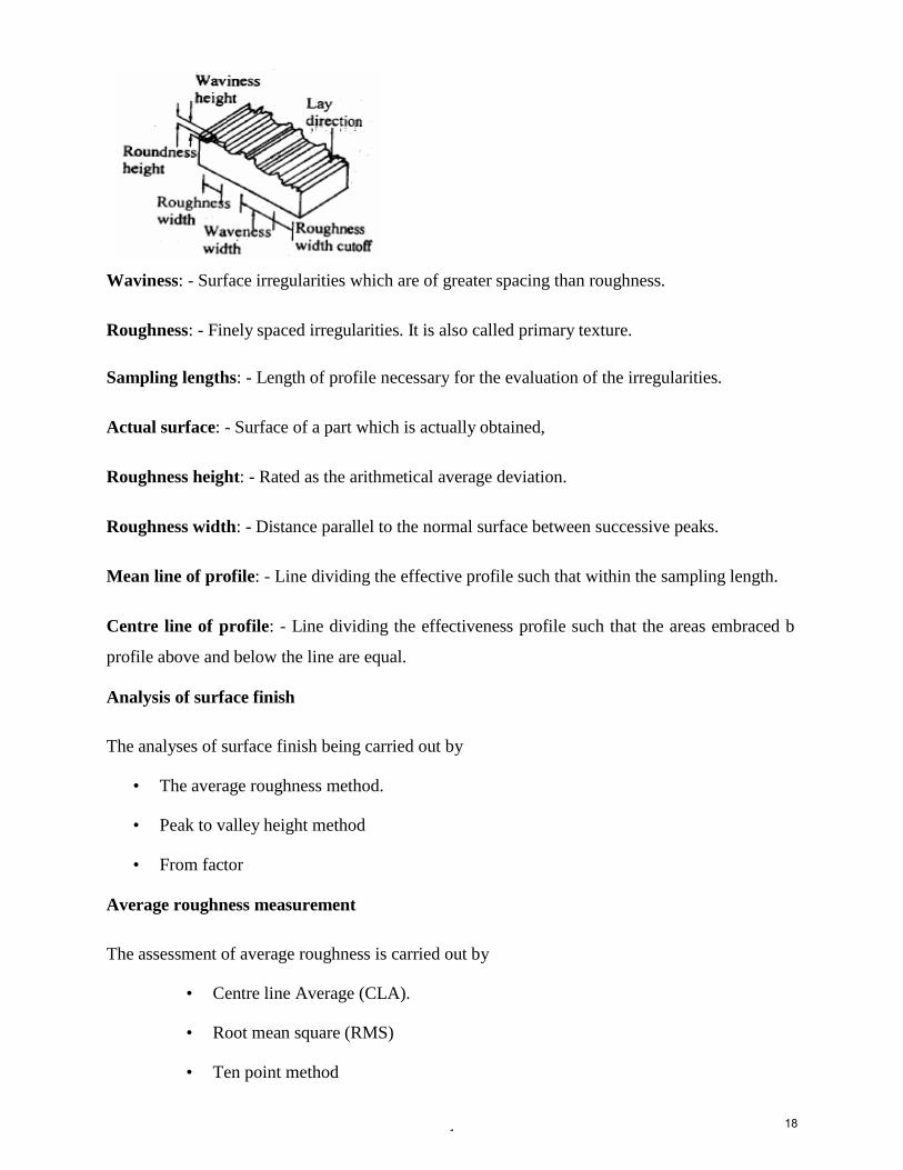
Waviness: - Surface irregularities which are of greater spacing than roughness.
Roughness: - Finely spaced irregularities. It is also called primary texture.
Sampling lengths: - Length of profile necessary for the evaluation of the irregularities.
Actual surface: - Surface of a part which is actually obtained,
Roughness height: - Rated as the arithmetical average deviation.
Roughness width: - Distance parallel to the normal surface between successive peaks.
Mean line of profile: - Line dividing the effective profile such that within the sampling length.
Centre line of profile: - Line dividing the effectiveness profile such that the areas embraced b
profile above and below the line are equal.
Analysis of surface finish
The analyses of surface finish being carried out by
• The average roughness method.
• Peak to valley height method
• From factor
Average roughness measurement
The assessment of average roughness is carried out by
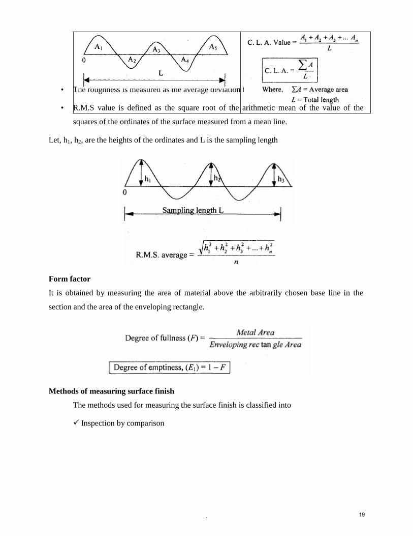
• Centre line Average (CLA).
• Root mean square (RMS)
• Ten point method
18
11
• The roughness is measured as the average deviation from the nominal surface.
• R.M.S value is defined as the square root of the arithmetic mean of the value of the
squares of the ordinates of the surface measured from a mean line.
Let, h1, h2, are the heights of the ordinates and L is the sampling length
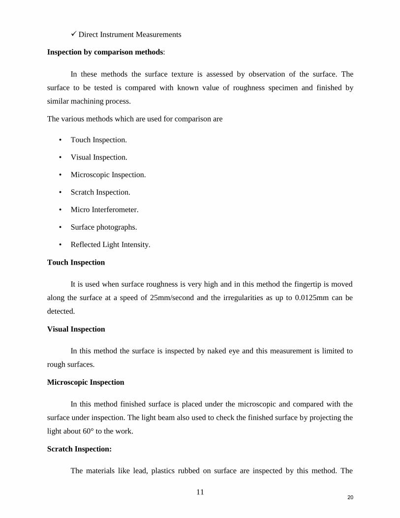
Form factor
It is obtained by measuring the area of material above the arbitrarily chosen base line in the
section and the area of the enveloping rectangle.
Methods of measuring surface finish
The methods used for measuring the surface finish is classified into
Inspection by comparison
19
11
Direct Instrument Measurements
Inspection by comparison methods:
In these methods the surface texture is assessed by observation of the surface. The
surface to be tested is compared with known value of roughness specimen and finished by
similar machining process.
The various methods which are used for comparison are
• Touch Inspection.
• Visual Inspection.
• Microscopic Inspection.
• Scratch Inspection.
• Micro Interferometer.
• Surface photographs.
• Reflected Light Intensity.
Touch Inspection
It is used when surface roughness is very high and in this method the fingertip is moved
along the surface at a speed of 25mm/second and the irregularities as up to 0.0125mm can be
detected.
Visual Inspection
In this method the surface is inspected by naked eye and this measurement is limited to
rough surfaces.
Microscopic Inspection
In this method finished surface is placed under the microscopic and compared with the
surface under inspection. The light beam also used to check the finished surface by projecting the
light about 60° to the work.
Scratch Inspection:
The materials like lead, plastics rubbed on surface are inspected by this method. The
20
12
impression of this scratches on the surface produced is then visualized.
Surface Photographs
Magnified photographs of the surface are taken with different types of illumination. The
defects like irregularities are appear as dark spots and flat portion of the surface appears as
bright.
Reflected light Intensity
A beam of light is projected on the surface to be inspected and the light intensity
variation on the surface is measured by a photocell and this measured value is calibrated
Direct instrument measurements
• Direct methods enable to determine a numerical value of the surface finish of any
surface.
• These methods are quantitative analysis methods and the output is used to operate
recording or indicating instrument.
• Direct Instruments are operated by electrical principles. These instruments are classified
into two types according to the operating principle.
Some of the direct measurement instruments are
• Stylus probe instruments.
• Tomlinson surface meter.
• Taylor-Hobson Talysurf
Tomlinson Surface meter
• The Tomlinson surface meter is a comparatively cheap and reliable instrument.
• This instrument uses mechanical-cum-optical means for magnification.
• It is designed by Dr. Tomlinson.
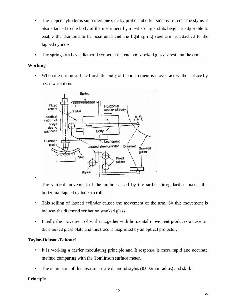
Construction
• In this the diamond stylus on the surface finish recorder is held by spring pressure against
the surface of a lapped cylinder.
21
13
• The lapped cylinder is supported one side by probe and other side by rollers. The stylus is
also attached to the body of the instrument by a leaf spring and its height is adjustable to
enable the diamond to be positioned and the light spring steel arm is attached to the
lapped cylinder.
• The spring arm has a diamond scriber at the end and smoked glass is rest on the arm.
Working
• When measuring surface finish the body of the instrument is moved across the surface by
a screw rotation.
•
The vertical movement of the probe caused by the surface irregularities makes the
horizontal lapped cylinder to roll.
• This rolling of lapped cylinder causes the movement of the arm. So this movement is
induces the diamond scriber on smoked glass.
• Finally the movement of scriber together with horizontal movement produces a trace on
the smoked glass plate and this trace is magnified by an optical projector.
Taylor-Hobson-Talysurf
• It is working a carrier modulating principle and It response is more rapid and accurate
method comparing with the Tomlinson surface meter.
• The main parts of this instrument are diamond stylus (0.002mm radius) and skid.
Principle
22
14
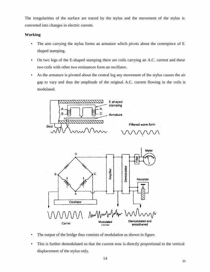
The irregularities of the surface are traced by the stylus and the movement of the stylus is
converted into changes in electric current.
Working
• The arm carrying the stylus forms an armature which pivots about the centrepiece of E
shaped stamping.
• On two legs of the E-shaped stamping there are coils carrying an A.C. current and these
two coils with other two resistances form an oscillator.
• As the armature is pivoted about the central leg any movement of the stylus causes the air
gap to vary and thus the amplitude of the original A.C. current flowing in the coils is
modulated.
• The output of the bridge thus consists of modulation as shown in figure.
• This is further demodulated so that the current now is directly proportional to the vertical
displacement of the stylus only.
23
15
• The demodulated output is caused to operate a pen recorder to produce a permanent
record. And the meter to give numerical assessment directly.
2 Marks Questions
1. What are the factor affecting Surface Roughness?
2. What are the methods used for measuring the surface finish?
3. Define the terms: Surface Roughness, Waviness, Flaw, Lay, and Sampling Length.
4. What is C.L.A and R.M.S Method?
5. What is the working principle of Taylor-Hobson-Talysurf?
6. Write the advantage of Taylor-Hobson-Talysurf?
24

16
25

17
26