Embed Size (px)
Citation preview

DOT/FAA/AR-04/50 Office of Aviation Research Washington, D.C. 20591
Comparative Testing to Assess the Equivalence of CEN and ASTM Test Methods for Composite Materials February 2005 Final Report This document is available to the U.S. public through the National Technical Information Service (NTIS), Springfield, Virginia 22161.
U.S. Department of Transportation Federal Aviation Administration

NOTICE
This document is disseminated under the sponsorship of the U.S. Department of Transportation in the interest of information exchange. The United States Government assumes no liability for the contents or use thereof. The United States Government does not endorse products or manufacturers. Trade or manufacturer's names appear herein solely because they are considered essential to the objective of this report. This document does not constitute FAA certification policy. Consult your local FAA aircraft certification office as to its use. This report is available at the Federal Aviation Administration William J. Hughes Technical Center's Full-Text Technical Reports page: actlibrary.tc.faa.gov in Adobe Acrobat portable document format (PDF).

Technical Report Documentation Page 1. Report No. DOT/FAA/AR-04/50
2. Government Accession No. 3. Recipient's Catalog No.
5. Report Date
February 2005
4. Title and Subtitle
COMPARATIVE TESTING TO ASSESS THE EQUIVALENCE OF CEN AND ASTM TEST METHODS FOR COMPOSITE MATERIALS 6. Performing Organization Code
7. Author(s)
Daniel O. Adams 8. Performing Organization Report No.
10. Work Unit No. (TRAIS)
9. Performing Organization Name and Address
Department of Mechanical Engineering University of Utah Salt Lake City, Utah 84112
11. Contract or Grant No.
12. Sponsoring Agency Name and Address
U.S. Department of Transportation Federal Aviation Administration
13. Type of Report and Period Covered
Final Report
Office of Aviation Research Washington, DC 20591
14. Sponsoring Agency Code
ACE-110 15. Supplementary Notes
The FAA William J. Hughes Technical Center Technical Monitor was Peter Shyprykevich. 16. Abstract
An initial assessment of equivalence between CEN and ASTM test methods was performed and documented in DOT/FAA/AR-04/24. That study recommended additional test data to assess test method equivalency for four types of tests. The results of the four types of tests are contained in this report. First, lamina compression testing was performed to investigate the effects of different specimen gage lengths between either the prEN 2850–B and SACMA SRM 1 test methods (5 and 4.75 mm, respectively) and the AMS 2980 and 3970 specifications (12.5 mm). The results suggest that the gage length difference investigated (4.75 mm versus 12.5 mm) can produce significant differences in the apparent lamina compression strength. However, this difference is believed to be due to specimen buckling that occurred for specimens with longer gage lengths, which is an unacceptable failure mode. Second, laminate compression tests were performed to investigate the method used to load the test fixture. The results suggest that the end-loaded test fixture shown in the SACMA SRM 3-94 test method is not suitable without additional clamping force applied near the specimen ends to prevent end-brooming failures. However, it is expected that through the modification of the existing test fixture to include more clamping bolts, an end-loaded test procedure can be produced that is capable of producing equivalent test results to the shear-loaded ASTM D 6484 test method. Third, in-plane shear testing was performed using ±45° type composite laminates loaded in tension to investigate laminate thickness effects. Test results showed that the 0.2% offset shear strength, the 5% shear strength measures, and the shear moduli calculated following the prEN 6031/AMS and ASTM D 3518 test methods are in good agreement and independent of laminate thickness over the thickness ranges specified in the two test methods. Thus, these two shear test methods are believed to produce equivalent results when testing either tape or fabric laminates. Finally, constituent content was determined to compare procedures EN 2564 Method A and ASTM D 3171 Method I procedure B. The results showed that EN 2564 Method A and ASTM D 3171 Method I procedure B produced similar values for both the fiber volume percent and the matrix volume percent. However, the increased accuracy of the ASTM D 3171 test method due to the larger specimen size and the greater weighing accuracy produced more realistic values of void volume fraction than the EN 2564 Method A test method. 17. Key Words
Composite materials, Mechanical property testing, Test methods
18. Distribution Statement
This document is available to the public through the National Technical Information Service (NTIS) Springfield, Virginia 22161.
19. Security Classif. (of this report)
Unclassified
20. Security Classif. (of this page)
Unclassified
21. No. of Pages
78 22. Price
Form DOT F1700.7 (8-72) Reproduction of completed page authorized

TABLE OF CONTENTS Page EXECUTIVE SUMMARY vii 1. INTRODUCTION TO COMPARATIVE EVALUATION 1
1.1 Background 1 1.2 Comparative Evaluation of Test Methods 2 1.3 Test Methods Recommended for Follow-On Testing 3
1.3.1 Lamina Compression Tests: Effects of Gage Length 3
1.3.2 Laminate Compression Tests: Effects of Loading Method 4
1.3.3 In-Plane Shear Tests: Effects of Specimen Thickness 4
1.3.4 Constituent Content Determination: Effects of Specimen Size and Weighing Accuracy 4
2. GENERAL DESCRIPTION OF COMPARATIVE TESTS 4
2.1 Materials 5 2.2 Moisture Conditioning 5
3. LAMINA COMPRESSION TESTS 6
3.1 Test Description 6 3.2 Lamina Compression Test Results 8
4. LAMINATE COMPRESSION TESTS 10
4.1 Test Description 10 4.2 Laminate Compression Test Results 13
5. IN-PLANE SHEAR TESTS 18
5.1 Test Description 18 5.2 In-Plane Shear Test Results 22
6. CONSTITUENT CONTENT DETERMINATION 28
6.1 Test Description 28 6.2 Constituent Content Determination Results 30
iii

7. SUMMARY OF RESULTS 32
8. REFERENCES 34
APPENDIX A—PHOTOGRAPHS OF FAILED SPECIMENS
LIST OF FIGURES Figure Page 1 Test Fixture Used for the Lamina Compression Tests 6
2 Lamina Compression Strengths From Tape and Fabric Laminates 9
3 Test Fixture Used for the Laminate Compression Tests (End Loading) 10
4 Shear Loading of Laminate Compression Test Fixture Using Hydraulic Grips 11
5 Test Setup for End-Loaded Laminate Compression Tests With Additional Clamping Force 14
6 Compression Strengths From Tape Laminates 17
7 Compression Strengths From Fabric Laminates 18
8 Test Setup Used for the In-Plane Shear Tests 20
9 In-Plane Shear Strengths From Tape Laminates at RT/Ambient Conditions 25
10 In-Plane Shear Strengths From Tape Laminates at 82ºC/Wet Conditions 25
11 In-Plane Shear Strengths From Fabric Laminates at RT/Ambient Conditions 26
12 In-Plane Shear Strengths From Fabric Laminates at 82ºC/Wet Conditions 26
13 In-Plane Shear Modulus From Tape Laminates 27
14 In-Plane Shear Modulus From Fabric Laminates 27
15 Constituent Content Determinations From Tape and Fabric Laminates 32
iv

LIST OF TABLES Table Page 1 Summary of Lamina Compression Tests 7 2 Lamina Compression Test Results 8 3 Summary of Laminate Compression Tests 12 4 Laminate Compression Test Results for 25/50/25 Tape Laminate 14 5 Laminate Compression Test Results for 50/40/10 Tape Laminate 15 6 Laminate Compression Test Results for 25/50/25 Fabric Laminate 15 7 Laminate Compression Test Results for 40/20/40 Fabric Laminate 16 8 Summary of In-Plane Shear Tests 19 9 In-Plane Shear Test Results of Tape Laminates 23 10 In-Plane Shear Test Results of Fabric Laminates 24 11 Summary of Constituent Content Determinations 29 12 Constituent Content Determination Results 31
v

LIST OF ACRONYMS
c.v. Coefficient of variation CACRC Commercial Aircraft Composite Repair Committee CEN Comité Européen de Normalisation FAA Federal Aviation Administration prEN 6031/ASM prEN 6031 with ASM additions and changes RT Room temperature SACMA Suppliers of Advanced Composite Materials Association St. Dev. Standard deviation U.S. United States
vi

EXECUTIVE SUMMARY
An initial assessment of equivalence between CEN and ASTM test methods was performed and documented in the Federal Aviation Administration report DOT/FAA/AR-04/24. That study recommended four types of tests be done to provide additional test data to assess test method equivalency. The results of the four types of tests are contained in this report. First, lamina compression testing was performed to investigate the effects of different specimen gage lengths between either the prEN 2850–B and SACMA SRM 1 test methods (5 and 4.75 mm, respectively) and the AMS 2980 and 3970 specifications (12.5 mm). The results suggest that the gage length difference investigated (4.75 mm versus 12.5 mm) can produce significant differences in the apparent lamina compression strength. However, this difference is believed to be due to specimen buckling that occurred for specimens with longer gage lengths, which is an unacceptable failure mode. Second, laminate compression tests were performed to investigate the method used to load the test fixture. The results suggest that the end-loaded test fixture shown in the SACMA SRM 3-94 test method is not suitable without additional clamping force applied near the specimen ends to prevent end-brooming failures. However, it is expected that through the modification of the existing test fixture to include more clamping bolts, an end-loaded test procedure can be produced that is capable of producing equivalent test results to the shear-loaded ASTM D 6484 test method. Third, in-plane shear testing was performed using ±45° type composite laminates loaded in tension to investigate laminate thickness effects. Test results showed that the 0.2% offset shear strength, the 5% shear strength measures, and the shear moduli calculated following the prEN 6031/AMS and ASTM D 3518 test methods are in good agreement and independent of laminate thickness over the thickness ranges specified in the two test methods. Thus, these two shear test methods are believed to produce equivalent results when testing either tape or fabric laminates. Finally, constituent content was determined to compare procedures EN 2564 Method A and ASTM D 3171 Method I procedure B. The results showed that EN 2564 Method A and ASTM D 3171 Method I procedure B produced similar values for both the fiber volume percent and the matrix volume percent. However, the increased accuracy of the ASTM D 3171 test method due to the larger specimen size and the greater weighing accuracy produced more realistic values of void volume fraction than the EN 2564 Method A test method.
vii/viii

1. INTRODUCTION TO COMPARATIVE EVALUATION.
1.1 BACKGROUND.
The original motivation for this comparative evaluation of United States (U.S.) and European test methods for composite materials dates back to the early 1990s. At that time, a composite materials characterization program was initiated to generate a dataset and subsequently qualify a composite material system for commercial aircraft repair [1]. The material to be qualified was a wet lay-up composite material that was processed with a vacuum-only cure and used for airframe repair. The material qualification program was performed according to SAE specification AMS 2980 [2] and Commercial Aircraft Composite Repair Committee (CACRC) requirements, which used Committee for European Standardization, or Comité Européen de Normalisation (CEN), test methods. The mechanical tests performed included tension, compression, in-plane shear, open-hole tension, filled-hole tension, open-hole compression, filled-hole compression, bearing, compression after impact, tension-tapered joint, and tension-stepped joint tests. At the completion of testing, the mechanical test results were processed into MIL Handbook 17-acceptable form to provide statistical data. In the mid-1990s, a MIL Handbook 17 committee reviewed the test methods used in this material qualification program and compared them to the test methods recommended by MIL Handbook 17 [3]. They noted that CEN test methods were used extensively in this qualification program, whereas MIL Handbook 17 focuses on ASTM test methods. The MIL Handbook 17 committee determined that the CEN and ASTM test methods differed in several aspects, raising concerns that the SAE-specified tests do not produce equivalent results to the MIL Handbook 17-recommended test methods. The results of the MIL Handbook 17 committee review were published by email in October 1995 [4]. Following this review, discussions continued between MIL Handbook 17 and CACRC personnel. Although the CACRC continued using the CEN test methods, similar ASTM test methods were added to the SAE specifications as an alternate for some tests. Additionally, for several types of tests included in both SAE AMS 2980 [2] (for wet lay-up material) and SAE AMS 3970 [5] (for prepreg material), several parameters were specified that limited potential differences in test results between the CEN and ASTM test methods. For several types of tests, however, it remained unclear if the ASTM and CEN test methods would produce equivalent test results. In May 2002, a joint meeting was held between CACRC and the MIL Handbook 17 Composite Materials Handbook Committee. Following this meeting, Mr. Rich Fields reviewed the test methods in the initial release of SAE AMS 3970 [5] and wrote a summary of findings and conclusions [6]. Mr. Fields concluded that the results from some CEN test methods would not be expected to be equivalent to the results for the same properties obtained using MIL Handbook 17-recommended test methods. Based on these events, an Federal Aviation Administration (FAA)-funded comparative investigation was initiated by the author. The first phase of the investigation focused on a detailed evaluation and comparison of the CEN and ASTM test methods. The results of the investigation, published in 2004 [7], are summarized in the following section. For those tests where the significance of an important difference could not be determined, follow-on mechanical tests were proposed as a second round of investigation. The results of the follow-on mechanical tests are the focus of this report.
1

1.2 COMPARATIVE EVALUATION OF TEST METHODS.
In June 2004, the author prepared a detailed test method comparison [7] directed towards assessing the equivalence of the different test methods (primarily CEN and ASTM) referred to in the SAE AMS 2980 and 3970 specifications. Of interest was both a direct comparison of the test methods as well as an investigation of the effects of additions and changes given in the AMS specifications. For several types of tests, both a CEN and an ASTM test method are referred to in the AMS specifications and were, therefore, used for comparison. In several other cases, however, only a CEN test method is referred to in the AMS specifications. For these cases, a similar ASTM test method was sought for comparison. For cases where no comparable ASTM test method existed, either a draft ASTM standard or a Suppliers of Advanced Composite Materials Association (SACMA)-recommended method was selected. For the lamina compression test, the AMS specifications referred only to a SACMA-recommended method. For this case, a comparable ASTM standard was identified and used for comparison. Of the CEN test methods used for comparison, several of the standards are currently draft or preliminary standards and are denoted as prEN test methods. Other test methods, which have been approved by CEN, are denoted as EN test methods. In total, two test methods were reviewed and compared for a total of 16 different types of tests. For each type of test, the results of the comparative evaluation were arranged into three comparison tables. The first table focused on the geometric features of the test specimen and test fixture. Included in this table were important dimensions and tolerances associated with both the test specimen and fixture. The second table focused on the parameters associated with the test procedure. Included were parameters associated with specimen preparation and instrumentation; procedures for specimen preconditioning, loading, and testing; and accuracy requirements for measured quantities. The third table focused on the procedures for data reduction and reporting. Included were the procedures, formulas, and statistical methods used to calculate and report test quantities. In addition to a detailed comparison of test method parameters, the significance of the differences in parameters was assessed and included in the comparison tables. For every parameter compared, an assessment of the equivalence was made using the following rating scale: • 0—No difference, essentially the same, not expected to produce any effect on the results
• 1—Insignificant difference, potential to produce an insignificant effect on the results
• 2—Minimal difference, difference of minimal significance, potential to produce a minimal effect on the results
• 3—Moderate difference, difference of moderate significance, potential to produce a moderate effect on the results
• 4—Major difference, difference of major significance, potential to produce a major effect on the results
2

For cases where an assessment of equivalence was not possible, a rating of not comparable was used. A brief summary of each test method comparison was provided, which emphasized the most significant differences between the test methods. Prior to publishing, an initial draft of these comparison tables was prepared by the author and distributed to the following group for evaluation. • Mr. Rich Fields, Lockheed Martin Orlando, Chairman of ASTM D 30 Committee and
Co-Chairman of MIL Handbook 17 Testing Working Group
• Mr. Peter Shyprykevich, Federal Aviation Administration
• Dr. Donald F. Adams, president of Wyoming Test Fixtures, Inc.
• Dr. John Tomblin, Director of the National Institute for Aviation Research at Wichita State University
Following a review of the comparison tables, the author and evaluators met at Wichita State University in August 2003 to discuss the comparison and assessment tables as well as to determine which tests would require follow-on testing to assess equivalence. As a result of this meeting, changes were made to both the format and the content of the comparison and assessment tables. The final comparison tables, along with a brief summary of the comparison, were published for the 16 test methods in an FAA report in June 2004 [7]. The final section of this report listed and briefly discussed four types of tests that were identified as requiring follow-on testing in the second round of this investigation to assess equivalence. 1.3 TEST METHODS RECOMMENDED FOR FOLLOW-ON TESTING.
Based on the comparative assessments of equivalence performed in reference 7, four of the sixteen types of tests were selected for follow-on testing to further assess test method equivalency. Note that these four tests only reflected the need for additional test data to assess equivalency and was not a reflection of their degree of equivalency relative to other tests. The four types of tests selected for follow-on testing and the parameter(s) to be investigated are described briefly in the following sections. 1.3.1 Lamina Compression Tests: Effects of Gage Length.
The test method comparison for lamina compression testing revealed a potentially significant difference in specimen gage lengths. Although similar gage lengths are listed for the prEN 2850-B and SACMA SRM 1 test methods (5 mm versus 4.75 mm, respectively), the AMS 2980 and 3970 specifications specify a 12.5-mm gage length. It is not well understood how this difference in gage length (4.75 mm versus 12.5 mm) will affect the delivered compression strengths produced in lamina compression testing. Thus, follow-on testing was recommended to determine the effects of specimen gage length on delivered lamina compression strength. Tests were proposed using specimens with both 4.75- and 12.5-mm gage length specimens.
3

1.3.2 Laminate Compression Tests: Effects of Loading Method.
The two test methods compared for laminate compression testing followed procedures generated for open-hole compression testing, but used a specimen without a hole. The test fixture specified in these test methods, SACMA SRM 3 and ASTM D 6484, was very similar. However, the method used to load the test fixture differs significantly and may produce differences in delivered compression strengths. Whereas the ASTM D 6484 has traditionally required hydraulic wedge grips to grip the test fixture, the SACMA SRM 3 test method allowed the test fixture to be end-loaded between two parallel platens of the test machine. It was noted that neither standard was intended for compression testing of specimens without a central hole. Further, in 2004, the ASTM D 6484 test method was modified to include both shear and end loading of the test fixture. Thus, follow-on testing was recommended to determine the effects of the loading method on the delivered compression strength of composite laminates. Testing was proposed with the test fixture gripped (hydraulic wedge grips) and end-loaded. 1.3.3 In-Plane Shear Tests: Effects of Specimen Thickness.
The test methods compared for in-plane shear testing both used ±45° type composite laminates loaded in tension. Although both the prEN 6031 test method and the AMS 2980 and 3970 specifications require an 8-ply +45° laminate for either unidirectional tape or woven fabric, ASTM D 3518 requires 16-, 20-, or 24-ply unidirectional tape laminates and 8-, 12-, or 16-ply woven fabric laminates. Since specimen thickness effects on strength have been reported in the literature [8], follow-on testing was recommended using multiple-thickness specimens fabricated from both prepreg tape and prepreg fabric materials. 1.3.4 Constituent Content Determination: Effects of Specimen Size and Weighing Accuracy.
Both test methods compared for constituent content determination, EN 2564 Method A and ASTM D 3171 Method I procedure B, used an acid digestion procedure to determine the constituent content of composite laminates. Two significant differences between the test methods were proposed for investigation in follow-on testing. First, the effect of the differences in the required specimen size reported between the test methods was proposed for investigation. Whereas EN 2564 requires a 2-mm-thick, 200-mm2 rectangular specimen, ASTM D 3171 requires a minimum surface area of 625 mm2 and specifies a minimum mass requirement. Second, the difference in the required weighing accuracy between the test methods was proposed for investigation. Although ASTM D 3171 requires that the weights be determined to the nearest 0.1 mg, EN 2564 only requires accuracy to the nearest ±1 mg. Both unidirectional prepreg laminates and prepreg fabric laminates were recommended for evaluation. 2. GENERAL DESCRIPTION OF COMPARATIVE TESTS.
Four types of tests were performed in this portion of the research investigation to help assess equivalency between the CEN and ASTM test methods. As stated earlier, the selection of these four tests for follow-on testing only reflected the need for additional test data to assess equivalency and was not a reflection of their degree of equivalency relative to other tests. Prior to discussing the detailed testing procedures and presenting the results for each type of test in the
4

following sections, the materials tested and the method used for specimen conditioning are presented. 2.1 MATERIALS.
Tests were performed using two different carbon/epoxy composite materials. (1) A carbon/epoxy unidirectional prepreg tape produced by Toray (America), Inc., designated as Toray T700G/#2510. This unidirectional prepreg tape had an areal weight of 150 g/m2. (2) A carbon/epoxy woven prepreg fabric produced by FiberCote Industries, designated as T300/E765. This plain weave prepreg fabric had an areal weight of 190 g/m2. Cured panels constructed from each of these materials were supplied to Wichita State University and subsequently forwarded to the University of Utah. Details on fabrication procedures used for the Toray T700G/#2510 tape laminates and the FiberCote T300/E765 fabric laminates are provided in references 9 and 10, respectively. 2.2 MOISTURE CONDITIONING.
For each of the three types of mechanical tests performed (lamina compression, laminate compression, and in-plane shear), specimens were tested at room temperature (RT)/ambient as well as at elevated temperatures following moisture conditioning. This section describes the procedure followed for moisture conditioning of specimens prior to mechanical testing. The test methods governing moisture conditioning are ASTM D 5229, “Standard Test Method for Moisture Absorption Properties and Equilibrium Conditioning of Polymer Matrix Composite Materials” [11], and prEN 2823, “Determination of the Effect of Exposure to Humid Atmosphere on Physical and Mechanical Characteristics” [12]. Additions and changes are specified in sections 6.2 and 6.3.4 of both AMS 2980 [2] and AMS 3970 [5]. Both test methods require that the specimens be conditioned in their final form, following all machining and tabbing operations. Traveler specimens are required if the actual test material cannot be properly weighed, as in the case where the specimens are tabbed. Whereas prEN 2823 requires the travelers to have a width and length greater than 25 mm and a mass of 1.5 grams, ASTM D 5229 requires the travelers to weigh more than 5 grams. For both test methods, the travelers must come from the same panel as the test specimens. The travelers used for this investigation satisfied both sets of requirements. The test specimens and travelers were humidity-aged using a laboratory convection oven maintained at a temperature of 70 ±2°C. The test specimens and travelers were placed onto plastic trays in covered plastic tubs with water placed in the tubs below the specimen racks. Using these covered plastic tubs resulted in a relative humidity of 85% ±5%, measured with a humidity sensor. For each set of test specimens, traveler specimens were used to monitor moisture absorption. When the maximum difference between two subsequent weighings divided by the maximum mass of the specimen was less than 5 × 10⁻⁴, the test specimens were properly conditioned. The weighings were performed at 168-hour (7-day) intervals.
5

3. LAMINA COMPRESSION TESTS.
3.1 TEST DESCRIPTION.
The test methods followed for lamina compression testing, prEN 2850 [13] and SACMA SRM 1R-94 [14], are similar to the test methods for determining the compressive properties of composite materials. Note that prEN 2850 describes two types of compression tests; this comparison is based on method B. Section 6.5.3 of AMS 2980 [2] and 3970 [5] specifications provide additions and changes only to prEN 2850-B; the SACMA SRM 1 standard is not referred to in either AMS specification. This type of compression test, sometimes referred to as a modified ASTM D 695 compression test, features an end-loaded, face-supported specimen. When compression strength determination specimens are tabbed, the short gage length between the tabs prevents the use of strain gages for modulus determinations. Thus, a second set of untabbed specimens are required for modulus determination. These untabbed specimens are not suited for compression strength determination, since the specimen ends typically crush before compression failure occurs in the specimen gage section. The test fixture used for both test methods, shown in figure 1, was obtained from Wyoming Test Fixtures, Inc. [15]. The fixture supports the face of the tabs on the tabbed specimen, but not the specimen gage length itself. The specimen is end-loaded through hardened steel plates.
FIGURE 1. TEST FIXTURE USED FOR THE LAMINA COMPRESSION TESTS
Comparison of specimen geometries from the two test methods [7] revealed several minor differences in dimensions and tolerances that were not expected to produce significant effects on results. However, a significant difference was identified in the specified gage lengths. Whereas similar gage lengths are listed for the prEN 2850-B and SACMA SRM 1 test methods (5 mm versus 4.75 mm, respectively, a result of round-off between U.S. Customary and SI units), the AMS 2980 and 3970 specifications, which modify the prEN 2850-B test method, specify a
6

12.5-mm gage length. Since it is not well understood how this difference in gage length (4.75 mm versus 12.5 mm) will affect the delivered compression strengths produced in lamina compression testing, mechanical testing was performed using specimens with both 4.75- and 12.5-mm gage lengths. Since the tabbed specimens used for strength determination were unsuitable for modulus determinations, only compression strength determinations were made in these tests. Both a unidirectional tape laminate and a fabric laminate with 100% of the plies in the (0º/90º) orientation were tested. As described in section 2.1, Toray T700G/#2510 unidirectional prepreg tape was used to produce the unidirectional tape laminate. This laminate was fabricated from eight prepreg layers, resulting in a [0]8 laminate. The fabric laminate was fabricated from eight 0/90 layers of FiberCote T300/E765 plain weave prepreg, resulting in a [(0/90)]4s laminate. Testing was performed both at RT/ambient as well as at 82ºC (180ºF) following moisture conditioning (82ºC/wet). A total of six specimens were tested per condition. Table 1 summarizes the lamina compression tests performed in this investigation and provides the nominal thicknesses of the laminates used.
TABLE 1. SUMMARY OF LAMINA COMPRESSION TESTS
Number of Specimens Tested
Test Method Test
Condition
Toray T700G/#2510 Tape Laminate
[0]8 1.3-mm Nominal
Thickness
FiberCote T300/E765 Fabric Laminate
[(0/90)]4s 3.0-mm Nominal
Thickness RT/Ambient 6 6 prEN 2850 w/AMS
Specifications (12.5-mm gage length)
82ºC/Wet 6 6
RT/Ambient 6 6 SACMA SRM 1R-94 (4.75-mm gage length) 82ºC/Wet 6 6
Specimen tabbing was performed using 1.6-mm-thick G-10 glass-fabric/epoxy, following the recommended tabbing procedure developed at the University of Utah [16]. For specimens to be tested at RT/ambient conditions, Hysol 907 epoxy was used to adhesively bond the tabs. For specimens that were moisture-conditioned and tested at hot/wet conditions, Loctite 9394 epoxy was used as the adhesive because it was determined that Hysol 907 epoxy had inadequate shear strength at 82ºC/wet conditions. Two different gage lengths were produced in the test specimens: 4.75 and 12.5 mm. After tabbing, the specimens were cut from the tabbed panel using a water-cooled surface grinder equipped with a diamond blade. For specimens to be tested following the prEN 2850-B procedure, the nominal specimen dimensions were 80 mm in length and 12.5 mm in width. For specimens tested following the SRM 1R-94 procedure, the nominal length was also 80 mm, but the width was increased to 15 mm. Width and thickness measurements for the prEN 2850-B specimens were taken using a flat anvil micrometer. The same flat anvil micrometer was used for width measurements on the SRM 1R-94 specimens; however, a double-ball interface micrometer was used for thickness measurements.
7

Tests were performed on a 100-kN capacity, computer-controlled MTS servo-hydraulic load frame. For the prEN 2850-B procedure, the specimen was clamped between the face supports using a bolt torque of 0.5 N-m. The SACMA SRM 1R-94 test method specifies a bolt torque between 0.7 and 1.0 N-m; a torque of 0.7 N-m was used. All tests were performed under a constant crosshead displacement rate of 1.0 mm/min, and all specimens were loaded to failure. For hot/wet testing, an Instron environmental chamber was placed into the load frame. The environmental chamber was maintained at 82ºC and wet towels were placed inside to increase the humidity within the chamber during testing.
As discussed previously, the tabbed specimens used for strength determination were not suitable for modulus determinations due to the short gage lengths between tabs. Thus, only the ultimate compressive strength was determined from these tests. The primary objective of these tests was to determine the effects of specimen gage length on the delivered compression strengths.
3.2 LAMINA COMPRESSION TEST RESULTS.
Table 2 presents the results of the lamina compression tests using both the Toray T700G/#2510 unidirectional [0]8 carbon/epoxy tape laminate and the FiberCote T300/E765 [(0/90)]4s plain weave fabric laminate. The average compression strength, standard deviation, and coefficient of variation are shown for each of the test conditions. Additionally, lamina compression strengths obtained from the test methods are compared for each material and test condition in figure 2. Photographs of all failed lamina compression specimens are shown in figures A-1 through A-8 in appendix A.
TABLE 2. LAMINA COMPRESSION TEST RESULTS
Compression Strength
Laminate Test
Condition Test Method Average (MPa)
Standard Deviation
(MPa)
Coefficient of Variation
(%) prEN 2850-B 12.5-mm gage length 837 33 3.9 RT/Ambient
SRM 1R-94 4.75-mm gage length 976 87 9.0
prEN 2850-B 12.5-mm gage length 715 49 6.8
Toray T700G/#2510 Tape Laminate [0]8
82ºC/Wet
SRM 1R-94 4.75-mm gage length 858 60 7.0
prEN 2850-B 12.5-mm gage length 701 61 8.6 RT/Ambient
SRM 1R-94 4.75-mm gage length 716 46 6.5
prEN 2850-B 12.5-mm gage length 340 40 11.8
FiberCote T300/E765 Fabric Laminate [(0/90)]4s
82ºC/Wet
SRM 1R-94 4.75-mm gage length 324 29 9.1
8
0
200
400
600
800
1000
1200
RT/Ambient 82º C/Wet
Com
pres
sion
Stre
ngth
, MPa
prEN 2850-B 12.5 mm gage lengthSRM 1R-944.75 mm gage length
RT/Ambient 82º C/Wet
Toray T700G/#2510Tape Laminate
FiberCote T300/E-765Fabric Laminate
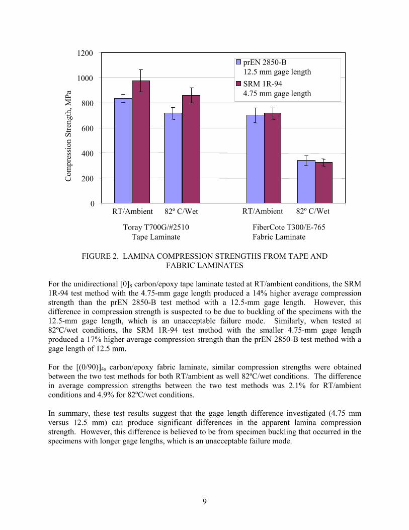
FIGURE 2. LAMINA COMPRESSION STRENGTHS FROM TAPE AND
FABRIC LAMINATES For the unidirectional [0]8 carbon/epoxy tape laminate tested at RT/ambient conditions, the SRM 1R-94 test method with the 4.75-mm gage length produced a 14% higher average compression strength than the prEN 2850-B test method with a 12.5-mm gage length. However, this difference in compression strength is suspected to be due to buckling of the specimens with the 12.5-mm gage length, which is an unacceptable failure mode. Similarly, when tested at 82ºC/wet conditions, the SRM 1R-94 test method with the smaller 4.75-mm gage length produced a 17% higher average compression strength than the prEN 2850-B test method with a gage length of 12.5 mm. For the [(0/90)]4s carbon/epoxy fabric laminate, similar compression strengths were obtained between the two test methods for both RT/ambient as well 82ºC/wet conditions. The difference in average compression strengths between the two test methods was 2.1% for RT/ambient conditions and 4.9% for 82ºC/wet conditions. In summary, these test results suggest that the gage length difference investigated (4.75 mm versus 12.5 mm) can produce significant differences in the apparent lamina compression strength. However, this difference is believed to be from specimen buckling that occurred in the specimens with longer gage lengths, which is an unacceptable failure mode.
9

4. LAMINATE COMPRESSION TESTS.
4.1 TEST DESCRIPTION.
Laminate compression tests were performed following two test methods developed exclusively for open-hole compression testing, but using specimens without a central hole. The first test method, SACMA SRM 3-94 test method, “Open-Hole Compression Properties of Orientated Fiber-Resin Composites,” [17] is referenced in section 6.5.8 of both AMS 2980 [2] and AMS 3970 [5] for laminate compression testing. Since the resulting test method is not similar to any ASTM compression tests without holes, a comparison was made to ASTM D 6484, “Standard Test Method for Open-Hole Compressive Strength of Polymer Matrix Composite Laminates,” [18], but using a specimen without a central hole. ASTM D 6484 is very similar to SACMA SRM 3-94 and therefore provided a good comparison. The test fixture specified for laminate compression testing in both test methods is commonly referred to as the Boeing Open-Hole Compression Test Fixture, as it was originally developed by The Boeing Company. The particular test fixture used in this investigation, obtained from Wyoming Test Fixtures Inc. [15], is shown in figure 3. This test fixture supports the test specimen continuously along both faces, but includes a V-shaped gap designed into the adjacent ends of the fixture halves to prevent contact from occurring during loading. Guide plates are used on each side of the fixture to maintain alignment of the assembly.
FIGURE 3. TEST FIXTURE USED FOR THE LAMINATE COMPRESSION TESTS
(END LOADING) Although this same test fixture is specified in the two test methods used, the method of load introduction differs significantly. The SACMA SRM 3-94 test method allows the assembled fixture, with specimen installed, to be end-loaded between two parallel platens, as shown in figure 3. Until 2004, ASTM D 6484 required the assembled fixture to be gripped at each end by
10
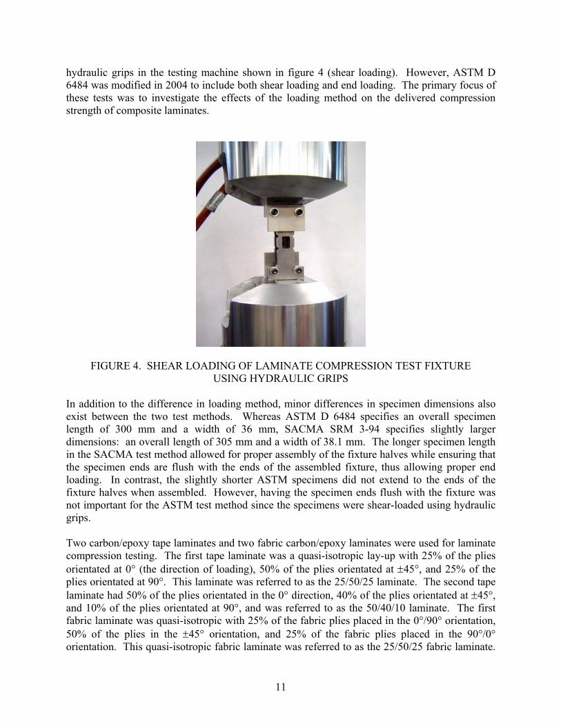
hydraulic grips in the testing machine shown in figure 4 (shear loading). However, ASTM D 6484 was modified in 2004 to include both shear loading and end loading. The primary focus of these tests was to investigate the effects of the loading method on the delivered compression strength of composite laminates.
FIGURE 4. SHEAR LOADING OF LAMINATE COMPRESSION TEST FIXTURE
USING HYDRAULIC GRIPS In addition to the difference in loading method, minor differences in specimen dimensions also exist between the two test methods. Whereas ASTM D 6484 specifies an overall specimen length of 300 mm and a width of 36 mm, SACMA SRM 3-94 specifies slightly larger dimensions: an overall length of 305 mm and a width of 38.1 mm. The longer specimen length in the SACMA test method allowed for proper assembly of the fixture halves while ensuring that the specimen ends are flush with the ends of the assembled fixture, thus allowing proper end loading. In contrast, the slightly shorter ASTM specimens did not extend to the ends of the fixture halves when assembled. However, having the specimen ends flush with the fixture was not important for the ASTM test method since the specimens were shear-loaded using hydraulic grips. Two carbon/epoxy tape laminates and two fabric carbon/epoxy laminates were used for laminate compression testing. The first tape laminate was a quasi-isotropic lay-up with 25% of the plies orientated at 0° (the direction of loading), 50% of the plies orientated at ±45°, and 25% of the plies orientated at 90°. This laminate was referred to as the 25/50/25 laminate. The second tape laminate had 50% of the plies orientated in the 0° direction, 40% of the plies orientated at ±45°, and 10% of the plies orientated at 90°, and was referred to as the 50/40/10 laminate. The first fabric laminate was quasi-isotropic with 25% of the fabric plies placed in the 0°/90° orientation, 50% of the plies in the ±45° orientation, and 25% of the fabric plies placed in the 90°/0° orientation. This quasi-isotropic fabric laminate was referred to as the 25/50/25 fabric laminate.
11

The second fabric laminate had 40% of its plies orientated at 0°/90°, 20% at ±45°, and 40% at 90°/0°, and was referred to as the 40/20/40 fabric laminate. For each laminate, six specimens were produced for each of the two test methods for both RT and hot/wet testing. As described in section 2.1, Toray T700G/#2510 unidirectional prepreg tape was used to fabricate the tape laminates, and FiberCote T300/E765 plain weave prepreg was used to fabricate the fabric laminates. Tests were performed both at RT/ambient as well as at elevated temperatures, following moisture conditioning (82ºC/wet). Table 3 summarizes the laminate compression tests performed and provides the nominal thicknesses of the laminates tested.
TABLE 3. SUMMARY OF LAMINATE COMPRESSION TESTS
Number of Specimens Tested Toray T700G/#2510
Tape Laminates FiberCote T300/E765
Fabric Laminates
Test Method Test
Condition
25/50/25 3.6-mm Nominal
Thickness
50/40/10 3.0-mm Nominal
Thickness
25/50/25 3.4-mm Nominal
Thickness
40/20/40 4.3-mm Nominal
Thickness RT/Ambient 6 6 6 6 SACMA
SRM 3-94 w/o Hole (End-Loaded)
82ºC/Wet 6 6 6 6
RT/Ambient 6 6 6 6 ASTM D 6484 w/o Hole (Shear-Loaded)
82ºC/Wet 6 6 6 6
Specimen tabbing was not required for the laminate compression tests. Specimens were cut from each laminate using a water-cooled surface grinder equipped with a diamond blade. The width and thickness measurements for all specimens were taken using a flat-face micrometer. Testing was performed on a 250-kN capacity computer-controlled MTS servo-hydraulic load frame equipped with hydraulic wedge grips. For testing performed according to the SACMA SRM 3-94 test method, the assembled fixture with the installed specimen was end-loaded using two parallel end plates with welded flanges that were gripped by the hydraulic wedge grips. The raised, rectangular frames on the end plates were included as a safety precaution to provide lateral constraint, so that the fixture would not slip from between the platens while being compression-loaded. As per the test procedure in SACMA SRM 3-94, the specimen was secured between the assembled fixture halves by tightening the two bolts on each half of the fixture to a torque of approximately 0.6 N-m. For laminate compression testing performed according to the ASTM D 6484 test method, the assembled test fixture with installed specimen was shear-loaded using MTS hydraulic wedge grips, as shown in figure 4. Prior to loading in the hydraulic grips, the two bolts on each half of the fixture were torqued to 7 N-m.
12

All laminate compression testing was performed under a constant crosshead displacement rate of 1.0 mm/min, and all specimens were loaded to failure. For hot/wet testing of the end-loaded SACMA SRM 3-94 specimens, an Instron environmental chamber was placed into the load frame so that the entire length of the specimen as well as the end plates were contained within the environmental chamber. The environmental chamber was maintained at 82ºC and wet towels were placed inside to increase the humidity within the chamber during testing. Due to size and temperature considerations, the hydraulic grips used to shear load the ASTM D 6484 specimens could not be enclosed in the environmental chamber. Thus, for the shear-loaded specimens, the Instron environmental chamber was placed immediately behind the hydraulic grips and an insulated extension to the environmental chamber was constructed to enclose the region of the test specimen located between the hydraulic grips. A thermocouple mounted to the surface of the specimen ensured that the specimen was maintained at a temperature of 82ºC. 4.2 LAMINATE COMPRESSION TEST RESULTS.
The initial test plan prescribed six specimens for both end loading and shear loading, as listed in table 3. As the testing of the end-loaded specimens commenced, however, brooming failures at the specimen ends occurred. This undesirable failure mode was believed to result from inadequate clamping pressure exerted on the specimen faces by the support fixture. As shown in figure 3, the end-loaded laminate compression specimen was clamped between the assembled fixture halves by two bolts on each fixture half. These two clamping bolts, located near the gage section of the specimen, were subjected to a rather minimal torque of approximately 0.6 N-m, per SACMA SRM 3-94 specifications. Efforts to prevent end-brooming failures by increasing the torque applied to the two bolts on each fixture half were not successful. An investigation into the test procedure used in the original Carbon Composite Wet Repair Qualification Program [1] revealed the use of two additional bolts in each fixture half located near the ends of the specimen, presumably to prevent end-brooming failures from occurring. Based on this observation, trial tests were performed using large C-clamps to apply additional clamping force to the fixture halves, as shown in figure 5. These trial tests yielded successful gage section failures, and the original test plan was modified so that only three specimens were tested in the original end-loaded configuration, according to SACMA SRM 3-94 specifications. The remaining three specimens were end-loaded with additional clamping force provided by the existing fixture bolts torqued to of 13.5 N-m and the added C-clamps torqued to 20 N-m. Laminate compression strengths obtained from the 25/50/25 and 40/20/40 tape laminates are presented in tables 4 and 5, respectively. Compression strengths from the 25/50/25 and 50/40/10 fabric carbon/epoxy laminates are presented in tables 6 and 7, respectively. In each table, the average compression strength, standard deviation, and coefficient of variation are shown for each for the test conditions investigated. Photographs of all failed lamina compression specimens are provided in figures A-9 through A-24 in appendix A.
13

FIGURE 5. TEST SETUP FOR END-LOADED LAMINATE COMPRESSION TESTS
WITH ADDITIONAL CLAMPING FORCE
TABLE 4. LAMINATE COMPRESSION TEST RESULTS FOR 25/50/25 TAPE LAMINATE
Compression Strength
Laminate Test
Condition Test Method Number of Specimens
Average (MPa)
Standard Deviation
(MPa)
Coefficient of Variation
(%) SACMA SRM 3-94 (End-Loaded) 3* 426 13 3.1
SACMA SRM 3-94 (End-Loaded) With added clamping
3 539 4.1 0.8
RT/Ambient
ASTM D 6484 (Shear-Loaded) 6 6003 40 8.6
SACMA SRM 3-94 (End-Loaded) 3** 380 21 5.6
SACMA SRM 3-94 (End-Loaded) With added clamping
3 409 12 2.9
Toray T700G/#2510 Tape Laminate 25/50/25
82ºC/Wet
ASTM D 6484 (Shear-Loaded) 6 400 27 6.7
*All three specimens failed at specimen end. **One specimen failed at specimen end.
14

TABLE 5. LAMINATE COMPRESSION TEST RESULTS FOR 50/40/10 TAPE LAMINATE
Compression Strength
Laminate Test
Condition Test Method Number of Specimens
Average (MPa)
Standard Deviation
(MPa)
Coefficient of Variation
(%) SACMA SRM 3-94 (End-Loaded) 3* 578 36 6.2
SACMA SRM 3-94 (End-Loaded) With added clamping
3** 628 53 8.5
RT/Ambient
ASTM D 6484 (Shear-Loaded) 6 659 21 3.1
SACMA SRM 3-94 (End-Loaded) 3* 493 87 17.6
SACMA SRM 3-94 (End-Loaded) With added clamping
3 524 92 17.5
Toray T700G/#2510 Tape Laminate 50/40/10
82ºC/Wet
ASTM D 6484 (Shear-Loaded) 6 526 52 9.9
*All three specimens failed at specimen end. **Two specimen failed at specimen end.
TABLE 6. LAMINATE COMPRESSION TEST RESULTS FOR 25/50/25 FABRIC LAMINATE
Compression Strength
Laminate Test
Condition Test Method Number of Specimens
Average (MPa)
Standard Deviation
(MPa)
Coefficient of Variation
(%) SACMA SRM 3-94 (End-Loaded) 3* 493 12 2.4
SACMA SRM 3-94 (End-Loaded) With added clamping
3 529 2.3 0.4
RT/Ambient
ASTM D 6484 (Shear-Loaded) 6 539 46 8.5
SACMA SRM 3-94 (End-Loaded) 3 341 14 4.1
SACMA SRM 3-94 (End-Loaded) With added clamping
3 373 9.9 2.7
FiberCote T300/E765 Fabric Laminate 25/50/25
82ºC/Wet
ASTM D 6484 (Shear-Loaded) 6 349 17 4.8
*All three specimens failed at specimen end.
15

TABLE 7. LAMINATE COMPRESSION TEST RESULTS FOR 40/20/40 FABRIC LAMINATE
Compression Strength
Laminate Test
Condition Test Method
Number of
Specimens Average (MPa)
Standard Deviation
(MPa)
Coefficient of Variation
(%) SACMA SRM 3-94 (End-Loaded) 3* 500 21 4.2
SACMA SRM 3-94 (End-Loaded) With added clamping
3 541 12 2.2
RT/Ambient
ASTM D 6484 (Shear-Loaded) 6 555 14 2.5
SACMA SRM 3-94 (End-Loaded) 3 418 7.7 1.9
SACMA SRM 3-94 (End-Loaded) With added clamping
3 437 13 2.9
FiberCote T300/E765 Fabric Laminate 40/20/40
82ºC/Wet
ASTM D 6484 (Shear-Loaded) 6 403 18 4.5
* Two specimens failed at specimen end. Laminate compression strengths obtained from the two tape laminates are compared for the two test methods in figure 6. For both laminates and at both test conditions, the end-loaded SACMA SRM 3-94 specimens exhibited the lowest compression strengths. For the 25/50/25 laminate tested at RT/ambient conditions, the average compression strength was 29% less than the average from the shear-loaded ASTM D 6484 specimens. As shown in appendix A, all three of the end-loaded SACMA SRM 3-94 specimens had end-brooming failures, whereas all ASTM D 6484 specimens failed in the gage section. When tested at 82ºC/wet conditions, however, the compression strengths obtained from the 25/50/25 tape laminate using these two test methods were within 5%. Whereas one of the three end-loaded SACMA SRM 3-94 specimens failed due to end brooming, all shear-loaded ASTM D 6484 specimens failed in the gage section. Similarly, the differences in compression strengths between the two test methods for the 50/40/10 tape laminate were 12% at RT/ambient conditions and 6% for 82ºC/wet conditions. For both test conditions, all three end-loaded SACMA SRM 3-94 specimens from the 50/40/10 laminate failed due to end brooming. For both tape laminates, the additional clamping force on the end-loaded SACMA SRM 3-94 specimens produced higher delivered compression strengths and more gage section failures than using the standard end-loading method in SACMA SRM 3-94. For specimens tested at RT/ambient conditions, the delivered compression strengths were improved to within 11% and 12% of the shear-loaded compression strengths for the 25/50/25 and 50/40/10 tape laminates, respectively. All three of the specimens tested with additional clamping force from the 25/50/25 laminate failed in the gage section, whereas two of the three 50/40/10 specimens failed due to end brooming. For tests performed with the two tape laminates at 82ºC/wet conditions, the compression strengths obtained were equivalent to those obtained using the ASTM D 6484 shear-loading test method, and gage section failures occurred in all specimens.
16

0
100
200
300
400
500
600
700
800C
ompr
essio
n St
reng
th, M
Pa
SACMA SRM 3-94 End LoadedSACMA SRM 3-94 With ClampingASTM D 6484 Shear Loaded
RT/Ambient 82º C/Wet RT/Ambient 82º C/Wet
25/50/25Tape Laminate
50/40/10Tape Laminate
0
100
200
300
400
500
600
700
800C
ompr
essio
n St
reng
th, M
Pa
SACMA SRM 3-94 End LoadedSACMA SRM 3-94 With ClampingASTM D 6484 Shear Loaded
RT/Ambient 82º C/Wet RT/Ambient 82º C/Wet
25/50/25Tape Laminate
50/40/10Tape Laminate
FIGURE 6. COMPRESSION STRENGTHS FROM TAPE LAMINATES
A comparison of the laminate compression strengths obtained from the fabric laminates are presented in figure 7. For both fabric laminates tested at RT/ambient conditions, the end-loaded SACMA SRM 3-94 specimens exhibited the lowest compression strengths. Compared to the average compression strength obtained using the shear-loaded ASTM D 6484 test method, the end-loaded SACMA SRM 3-94 test method produced compression strengths that were 9% and 10% lower for the 25/50/25 and 40/20/40 laminates, respectively. All three of the 25/50/25 specimens and two of the three 40/20/40 specimens that were end-loaded in accordance with SACMA SRM 3-94 specifications failed due to end brooming. In contrast, all specimens from the fabric laminates that were shear-loaded following ASTM D 6484 specifications failed in the gage section. When tested at 82º C/wet conditions, however, the compression strengths obtained using the two test methods were within 4% for both fabric laminates. All of the end- and shear-loaded fabric specimens tested at 82ºC/wet conditions failed in the specimen gage section. For both fabric laminates tested at RT/ambient conditions, the additional clamping force on the end-loaded SACMA SRM 3-94 specimens produced average compression strengths that were within 2.5% of the corresponding shear-loaded ASTM D 6484 compression strengths. Further, the additional clamping force resulted in gage section failures for all fabric specimens tested. For the two fabric laminates tested at 82ºC/wet conditions, the average compression strengths from the end-loaded specimens with additional clamping force were up to 4% higher than obtained from shear-loaded ASTM D 6484 specimens.
17

0
100
200
300
400
500
600
700C
ompr
essio
n St
reng
th, M
Pa
SACMA SRM 3-94 End LoadedSACMA SRM 3-94 With ClampingASTM D 6484 Shear Loaded
RT/Ambient 82º C/Wet RT/Ambient 82º C/Wet
25/50/25Fabric Laminate
40/20/40Fabric Laminate
0
100
200
300
400
500
600
700C
ompr
essio
n St
reng
th, M
Pa
SACMA SRM 3-94 End LoadedSACMA SRM 3-94 With ClampingASTM D 6484 Shear Loaded
RT/Ambient 82º C/Wet RT/Ambient 82º C/Wet
25/50/25Fabric Laminate
40/20/40Fabric Laminate
FIGURE 7. COMPRESSION STRENGTHS FROM FABRIC LAMINATES
In summary, these test results suggest that the test fixture shown in the SACMA SRM 3-94 test method is not suitable for end loading of laminate compression specimens without additional clamping force applied near the specimen ends to prevent end-brooming failures. Results from this investigation suggest that the addition of clamping force to the specimen near the ends can reduce the occurrence of end-brooming failures, subsequently producing higher delivered compression strengths. Since the clamping force provided by C-clamps in this investigation were not adequate to eliminate end-brooming failures in all cases, it cannot be concluded that end loading of the laminate compression test specimens produces equivalent results to shear loading. However, it is expected that through the modification of the existing test fixture to include more clamping bolts, an end loaded test procedure can be produced that is capable of producing equivalent test results to the current shear-loaded ASTM D 6484 test method. 5. IN-PLANE SHEAR TESTS.
5.1 TEST DESCRIPTION.
In-plane shear tests were performed following two test methods that used ±45° type laminates loaded in tension: prEN 6031 [19] and ASTM D 3518 [20]. The prEN 6031 test method followed in these tests were performed using the additions and modifications given in section 6.5.4 of both AMS 2980 [2] and AMS 3970 [5]. The test method comparison completed in Phase I of this investigation [7] revealed one potentially significant difference in the prescribed specimen thickness. Although both the prEN 6031 test method and the AMS 2980 and 3970
18

specifications require an 8-ply ±45° laminate for either unidirectional tape or woven fabric, ASTM D 3518 requires 16-, 20-, or 24-ply unidirectional tape laminates or 8-, 12-, or 16-ply woven fabric laminates. As discussed in section 1.3.3, a specimen thickness effect on strength has been reported previously [8], resulting in lower delivered shear strengths from thinner ±45° specimens. To further investigate the effects of specimen thickness, mechanical testing was performed using multiple-thickness specimens fabricated from both prepreg tape and prepreg fabric materials. In-plane shear tests were performed on three carbon/epoxy tape laminates and two carbon/epoxy fabric laminates, all with 100% of the fibers in the ±45º orientations. The three tape laminates were 4-ply [±45]s, 8-ply [±45]2s, and 16-ply [±45]4s. The two fabric laminates were 4-ply [(±45)]s and 8-ply [(±45)]2s. As described in section 2.1, Toray T700G/#2510 unidirectional prepreg tape was used to fabricate the tape laminates, whereas FiberCote T300/E765 plain weave prepreg was used to fabricate the fabric laminates. Testing was performed both at RT/ambient as well as at elevated temperatures, following moisture conditioning (82ºC/wet). A total of six specimens were tested per condition. Table 8 summarizes the in-plane shear tests performed in this investigation and provides the nominal thicknesses of the laminates used.
TABLE 8. SUMMARY OF IN-PLANE SHEAR TESTS
Number of Specimens Tested Toray T700G/#2510
Tape Laminates FiberCote T300/E765
Fabric Laminates
Test Condition
4-ply [±45]s
0.6-mm Nominal
Thickness
8-ply [±45]2s1.2-mm Nominal
Thickness
16-ply [±45]5s2.5-mm Nominal
Thickness
4-ply [(±45)]s0.9-mm Nominal
Thickness
8-ply [(±45)]2s1.7-mm Nominal
Thickness RT/Ambient 6 6 6 6 6 82ºC/Wet 6 6 6 6 6
The tabbing of specimens, although optional in the ASTM D 3518 test method, was performed on all in-plane shear specimens tested. Specimen tabbing was performed using 1.6-mm-thick G-10 glass-fabric/epoxy, following the recommended tabbing procedure developed at the University of Utah [16]. For specimens tested at RT/ambient conditions, Hysol 907 epoxy was used to adhesively bond the tabs. For specimens that were moisture-conditioned and tested at hot/wet conditions, Loctite 9394 epoxy was used as the adhesive. After tabbing, the specimens were cut from the tabbed panel using a water-cooled surface grinder equipped with a diamond blade. The overall specimen dimensions were 230 mm in length and 25 mm in width, with a gage length of 130 mm. Although only one set of six specimens was tested for each condition, the final dimensions were measured twice, each time in accordance with a specific test method. For ASTM D 3518, width measurements were taken with a flat-face micrometer, and thickness measurements were taken with a double-ball interface micrometer. For prEN 6031, width measurements were taken with a vernier caliper, and
19

thickness measurements were taken with a flat-face micrometer. The measurements that were taken according to each test method were subsequently used to calculate the material properties as specified in each test method. In general, the area measurements taken using the different measurement devices were within 1%-2% for specimens from both the tape and fabric laminates. Strain gages were used on all specimens for modulus measurement. Two Measurements Group CEA-060250UW-350 strain gages were bonded to a single surface of each specimen using M-Bond 200 adhesive. One strain gage was aligned in the direction of the applied load (0° direction), and the other gage was oriented transversely to the loading direction (90° direction). Both gages were centered across the specimen width and placed near the center of the gage length. Tests were performed on a 100-kN capacity, computer-controlled MTS servo-hydraulic load frame. A Measurements Group 2100 strain gage conditioner/amplifier system was used for strain gage measurements. A test speed of 2 mm/min was used in all tests. Mechanical wedge grips were used to grip the specimen as shown in figure 8. The grips were tightened on the specimen by manually turning a screw mechanism. A universal joint was used between the upper grip and the load cell. For hot/wet testing, an Instron environmental chamber was placed into the load frame. The environmental chamber was maintained at 82ºC and wet towels were placed inside to increase the humidity within the chamber during testing.
FIGURE 8. TEST SETUP USED FOR THE IN-PLANE SHEAR TESTS
20

Following testing, shear strains and shear stresses were calculated using the expressions yixii εεγ −=12 (1) and
A
Pii 212 =τ , (2)
where:
i12γ = shear strain at i-th data point
xiε = longitudinal normal strain at i-th data point
yiε = lateral normal strain at i-th data point
12τ = shear stress at i-th data point
iP = load at i-th data point A = cross-sectional area
In-plane shear strength and shear modulus properties were calculated according to the two test methods. For ASTM D 3518, the shear strength was defined as the maximum shear stress at or below 5% shear strain. An optional calculation of the 0.2% offset shear strength was performed for comparison purposes. The 0.2% offset shear strength was defined as the value of shear stress corresponding to the intersection of the shear stress versus shear strain curve and the shear modulus offset by 0.2% shear strain. For prEN 6031 with the AMS additions and changes (prEN 6031/AMS), three shear strength values were calculated. The first shear strength value, the 0.2% offset shear strength, was defined the same as for ASTM D 3518. Thus, the only source for the differences in the 0.2% offset shear strengths calculated from the two test methods were due to the different cross-sectional area measurements. The second measure, the shear strength at 5% strain, was defined as the shear stress achieved at 5% shear strain. The third measure, the ultimate shear strength, was defined as the maximum recorded shear stress recorded during testing. Note that since ASTM D 3518 defines the maximum shear stress as the maximum value at or below 5% shear strain, this value was expected to compare well with the shear strength at 5% strain from the prEN 6031/AMS test method if the shear stress continued to increase up to 5% shear strain. For the modulus determination, ASTM D 3518 specifies that the chord modulus be taken over a 4000 ±200 µε shear strain range with the lower strain point in the range of 1500 to 2500 µε. In this study, the reference points of 2000 and 6000 µε were used. For prEN 6031/AMS, the shear modulus was calculated using strain reference points between 2000 and 6000 µε. Thus, the method of shear modulus measurement between the two test methods was the same. As a result, the only differences in the calculated shear moduli between the two test methods would result from the different methods used to measure the cross-sectional area.
21

5.2 IN-PLANE SHEAR TEST RESULTS.
Tables 9 and 10 present the results of the in-plane shear tests of the Toray T700G/#2510 carbon/epoxy tape laminates and the FiberCote T300/E765 plain weave fabric laminates, respectively. The average shear strength and shear modulus values are listed, along with the standard deviation (St. Dev.) and coefficient of variation (c.v.) for each of the test conditions investigated. As described in section 5.1, two shear strength measures were calculated according to ASTM D 3518 specifications and three shear strength measures from prEN 6031/AMS. Photographs of all failed lamina compression specimens are shown in figures A-25 through A-34 in appendix A. As noted in table 9, three of the six, four-ply tape specimens tested at RT/ambient conditions and one of the six, four-ply specimens tested at 82ºC/wet conditions failed prior to achieving a 5% shear strain. For these two test conditions, the calculation of the prEN 6031/AMS shear strength at 5% strain was based on the remaining specimens. Of the remaining three tape specimens tested at RT/ambient conditions, two specimens experienced failure in one of the strain gages, therefore, the 5% shear strain reading was estimated based on the output of the one remaining strain gage. Since the specimens continued to load past the point of strain gage failure, these strain gage failures were believed to be produced by localized failures at the specimen surface. Shear strengths obtained from the prEN 6031/AMS and ASTM D 3518 test methods are compared in figures 9 and 10 for the tape laminates tested at RT/ambient and 82ºC/wet conditions, respectively. For each test condition, the five shear strength measures are plotted for each of the three laminate thicknesses. As expected, the 0.2% offset shear strengths from the prEN 6031/AMS and ASTM D 3518 test methods were very similar. Since all 8- and 16-ply tape specimens achieved a shear strain of 5% prior to failure, the ASTM D 3518 shear strength (maximum shear stress at or below 5% shear strain) was similar to the prEN 6031/AMS 5% shear strength. Since some of the four-ply tape specimens failed to reach a shear strain of 5% prior to failure, a comparison of these two shear strength values is less meaningful. For all cases other than the four-ply tape specimens, the prEN 6031/AMS ultimate shear strength was considerably higher than either the ASTM D 3518 shear strength or the prEN 6031/AMS 5% shear strength, indicating a considerable increase in shear stress beyond a 5% shear strain. Shear strengths obtained for the fabric laminates tested at RT/ambient and 82ºC/wet conditions are compared in figures 11 and 12, respectively. Similar to the results obtained for the tape laminates, the 0.2% offset shear strengths from the prEN 6031/AMS and ASTM D 3518 test methods were very similar. Further, the prEN 6031/AMS 5% shear strength was within 2% of the corresponding ASTM D 3518 shear strength (maximum shear stress at or below 5% shear strain). As the thickness of the fabric laminate increased from four to eight plies, the prEN 6031/AMS 5% shear strength and the ASTM D 3518 shear strength decreased slightly at RT/ambient conditions but increased slightly at 82ºC/wet conditions. However, neither change in these two shear strength measures was statistically significant. An increase in the prEN 6031 ultimate shear strength of 7% and 10% was observed for the RT/ambient and 82ºC/wet conditions, respectively, as the laminate thickness was increased from four to eight plies.
22

TAB
LE 9
. IN
-PLA
NE
SHEA
R T
EST
RES
ULT
S O
F TA
PE L
AM
INA
TES
Shea
r Stre
ngth
Sh
ear M
odul
us
prEN
603
1/A
MS
AST
M D
351
8
Test
C
ondi
tion
Lam
inat
e
0.2%
Off
set
Stre
ngth
(M
Pa)
Stre
ngth
at
5% S
train
(M
Pa)
Ulti
mat
e St
reng
th
(MPa
)
0.2%
Off
set
Stre
ngth
(M
Pa)
Shea
r St
reng
th
(MPa
)
AST
M
D 3
518
Mod
ulus
(G
Pa)
prEN
603
1 M
odul
us
(GPa
) A
vg.
61.4
88.
9**
85.9
62.0
81.7
4.52
4.47
St. D
ev.
3.05
3.
07**
11
.8
3.00
7.
16
0.
230.
23[±
45] s
(4 p
ly)
c.v.
(%)
5.0
3.5*
* 13
.7
4.8
8.8
5.1
5.0
Avg
.
56
.285
.410
756
.585
.94.
404.
37St
. Dev
. 1.
72
1.28
1.
92
1.72
1.
16
0.05
0.05
[±
45] 2
s (8
ply
) c.
v. (%
) 3.
1 1.
5 1.
8 3.
0 1.
4 1.
2 1.
2 A
vg.
54.5
85.0
110
54.7
85.2
4.24
4.22
St. D
ev.
1.04
1.
77
14.2
1.
12
1.76
0.
100.
10
RT/
Am
bien
t
[±45
] 4s
(16
ply)
c.
v. (%
) 1.
9 2.
1 12
.9
2.0
2.1
2.4
2.4
Avg
. 35
.2
48.
6*
56.8
35
.7
47.0
2.
712.
66
St. D
ev.
0.97
0
.97*
13
.1
0.75
5.
33
0.05
0.07
[±
45] s
(4 p
ly)
c.v.
(%)
2.8
2.0
* 23
.0
2.1
11.3
1.
8 2.
5 A
vg.
33.6
48.6
72.7
33.9
48.8
2.74
2.71
St. D
ev.
1.79
0.
26
3.54
1.
82
0.66
0.
050.
05
[±45
] 2s
(8 p
ly)
c.v.
(%)
5.3
0.5
4.9
5.4
1.3
1.8
1.9
Avg
.
33
.246
.175
.233
.446
.02.
712.
70St
. Dev
. 1.
16
1.63
2.
91
1.14
1.
28
0.07
0.06
82ºC
/Wet
[±45
] 4s
(16
ply)
c.
v. (%
) 3.
5 3.
5 3.
9 3.
4 2.
8 2.
6 2.
3
23
*One
of t
he si
x sp
ecim
ens f
aile
d pr
ior t
o 5%
shea
r stra
in; c
alcu
latio
ns w
ere
base
d on
the
rem
aini
ng fi
ve sp
ecim
ens.
**Th
ree
of th
e si
x sp
ecim
ens f
aile
d pr
ior t
o 5%
shea
r stra
in; c
alcu
latio
ns w
ere
base
d on
the
rem
aini
ng th
ree
spec
imen
s.

TAB
LE 1
0. I
N-P
LAN
E SH
EAR
TES
T R
ESU
LTS
OF
FAB
RIC
LA
MIN
ATE
S
Shea
r Stre
ngth
Sh
ear M
odul
us
prEN
603
1/A
MS
AST
M D
351
8
Test
C
ondi
tion
Lam
inat
e
0.2%
Off
set
Stre
ngth
(M
Pa)
Stre
ngth
at
5% S
train
(M
Pa)
Ulti
mat
e St
reng
th
(MPa
)
0.2%
Off
set
Stre
ngth
(M
Pa)
Shea
r St
reng
th
(MPa
)
AST
M
D 3
518
Mod
ulus
(G
Pa)
prEN
603
1 M
odul
us
(GPa
) A
vg.
63.3
85
.893
.163
.0
87.1
6.19
6.10
St. D
ev.
1.89
2.
01
1.43
5.
27
2.42
0.
200.
19
[±45
] s (4
ply
) c.
v. (%
) 3.
0 2.
3 1.
5 8.
4 2.
8 3.
3 3.
0 A
vg.
65.3
89.2
99.2
65.7
89.8
6.43
6.38
St. D
ev.
0.44
4.
28
2.33
0.
56
4.22
0.
180.
17
RT/
Am
bien
t
[±45
] 2s
(8 p
ly)
c.v.
(%)
0.7
4.8
2.3
0.8
4.7
2.7
2.6
Avg
. 29
.2
43.1
58.6
29.4
43
.42.
442.
42St
. Dev
. 2.
00
1.79
1.
85
1.88
1.
55
0.12
0.12
[±
45] s
(4 p
ly)
c.v.
(%)
6.8
4.2
3.2
6.4
3.6
4.8
4.9
Avg
.
28
.739
.664
.528
.939
.82.
252.
24St
. Dev
. 2.
17
2.11
2.
75
2.13
2.
05
0.11
0.11
82ºC
/Wet
[±45
] 2s
(8 p
ly)
c.v.
(%)
7.6
5.3
4.3
7.4
5.1
5.0
4.9
24

0
20
40
60
80
100
120
140
Shea
r Stre
ngth
, MPa
prEN 6031 0.2% Offset Strength
prEN 6031Strength at 5% Strain
prEN 6031 Ultimate StrengthASTM D 3518 Strength
ASTM D 3518 0.2% Offset Strength
4 plyTape Laminate
8 plyTape Laminate
16 plyTape Laminate
0
20
40
60
80
100
120
140
Shea
r Stre
ngth
, MPa
prEN 6031 0.2% Offset Strength
prEN 6031Strength at 5% Strain
prEN 6031 Ultimate StrengthASTM D 3518 Strength
ASTM D 3518 0.2% Offset Strength
4 plyTape Laminate
8 plyTape Laminate
16 plyTape Laminate
FIGURE 9. IN-PLANE SHEAR STRENGTHS FROM TAPE LAMINATES AT
RT/AMBIENT CONDITIONS
0
10
20
30
40
50
60
70
80
90
Shea
r Stre
ngth
, MPa
4 plyTape Laminate
8 plyTape Laminate
16 plyTape Laminate
prEN 6031 0.2% Offset Strength
prEN 6031Strength at 5% Strain
prEN 6031 Ultimate StrengthASTM D 3518 Strength
ASTM D 3518 0.2% Offset Strength
0
10
20
30
40
50
60
70
80
90
Shea
r Stre
ngth
, MPa
4 plyTape Laminate
8 plyTape Laminate
16 plyTape Laminate
prEN 6031 0.2% Offset Strength
prEN 6031Strength at 5% Strain
prEN 6031 Ultimate StrengthASTM D 3518 Strength
ASTM D 3518 0.2% Offset Strength
FIGURE 10. IN-PLANE SHEAR STRENGTHS FROM TAPE LAMINATES AT 82ºC/WET CONDITIONS
The results shown in figures 9-12 indicate, with the exception of the four-ply tape laminate, that the 0.2% offset shear strengths calculated according to the prEN 6031/AMS and ASTM D 3518 specifications are equivalent. Further, these quantities do not change in a statistically significant manner as the thickness is increased. Similarly, with the exception of the four-ply tape laminate, the ASTM D 3518 shear strength (maximum shear stress at or below 5% shear strain) is equivalent to the prEN 6031/AMS 5% shear strength for both the tape and fabric laminates.
25

Since both prEN 6031/AMS and ASTM D 3518 specify minimum laminate thicknesses of eight plies, both the 0.2% offset shear stress and the shear strength at 5% strain (up to 5% shear strain for ASTM D 3518) are equivalent for the two test methods.
0
20
40
60
80
100
120Sh
ear S
treng
th, M
Pa
prEN 6031 0.2% Offset Strength
prEN 6031Strength at 5% Strain
prEN 6031 Ultimate StrengthASTM D 3518 Strength
ASTM D 3518 0.2% Offset Strength
4 plyFabric Laminate
8 plyFabric Laminate
0
20
40
60
80
100
120Sh
ear S
treng
th, M
Pa
prEN 6031 0.2% Offset Strength
prEN 6031Strength at 5% Strain
prEN 6031 Ultimate StrengthASTM D 3518 Strength
ASTM D 3518 0.2% Offset Strength
4 plyFabric Laminate
8 plyFabric Laminate
FIGURE 11. IN-PLANE SHEAR STRENGTHS FROM FABRIC LAMINATES AT
RT/AMBIENT CONDITIONS
0
10
20
30
40
50
60
70
80
Shea
r Stre
ngth
, MPa
4 plyFabric Laminate
8 plyFabric Laminate
prEN 6031 0.2% Offset Strength
prEN 6031Strength at 5% Strain
prEN 6031 Ultimate StrengthASTM D 3518 Strength
ASTM D 3518 0.2% Offset Strength
0
10
20
30
40
50
60
70
80
Shea
r Stre
ngth
, MPa
4 plyFabric Laminate
8 plyFabric Laminate
prEN 6031 0.2% Offset Strength
prEN 6031Strength at 5% Strain
prEN 6031 Ultimate StrengthASTM D 3518 Strength
ASTM D 3518 0.2% Offset Strength
FIGURE 12. IN-PLANE SHEAR STRENGTHS FROM FABRIC LAMINATES AT
82ºC/WET CONDITIONS
26

Shear moduli obtained from the prEN 6031 and ASTM D 3518 test methods are compared in figures 13 and 14 for the tape and fabric laminates, respectively. As discussed in section 2.5, the method of shear modulus measurement between the two test methods was the same. Thus, any differences in the calculated shear moduli between the two test methods are a result of the different methods used to measure the cross-sectional area. For all laminates and test conditions, the difference in shear modulus between the prEN 6031 and ASTM D 3518 test methods was less than 2%.
0
0.5
1
1.5
2
2.5
3
3.5
4
4.5
5
Shea
r Mod
ulus
, GPa
RT/Ambient 82º C/Wet
4 ply 8 ply 16 ply 4 ply 8 ply 16 ply
prEN 6031
ASTM 3518
0
0.5
1
1.5
2
2.5
3
3.5
4
4.5
5
Shea
r Mod
ulus
, GPa
RT/Ambient 82º C/Wet
4 ply 8 ply 16 ply 4 ply 8 ply 16 ply
prEN 6031
ASTM 3518
FIGURE 13. IN-PLANE SHEAR MODULUS FROM TAPE LAMINATES
0
1
2
3
4
5
6
7
Shea
r Mod
ulus
, GPa
prEN 6031
ASTM 3518
RT/Ambient 82º C/Wet
4 ply 8 ply 4 ply 8 ply0
1
2
3
4
5
6
7
Shea
r Mod
ulus
, GPa
prEN 6031
ASTM 3518
RT/Ambient 82º C/Wet
4 ply 8 ply 4 ply 8 ply
FIGURE 14. IN-PLANE SHEAR MODULUS FROM FABRIC LAMINATES
27

Referring to figure 13, a small decrease in the average shear modulus with increasing laminate thickness is observed for the tape laminates tested at RT/ambient conditions. Figure 14 shows a small increase in the average shear modulus with increasing laminate thickness for the fabric laminates tested at RT/ambient conditions. Note, however, that neither change is statistically significant. Similarly, the small decrease in shear modulus with increasing laminate thickness for the fabric laminates tested at 82ºC/wet conditions is not statistically significant. In summary, the 0.2% offset shear strength, the 5% shear strength measures, and the shear moduli calculated following the prEN 6031/AMS and ASTM D 3518 test methods were in good agreement and independent of laminate thickness over the thickness ranges specified in the two test methods. Thus, these two shear test methods are believed to produce equivalent results when testing either tape or fabric laminates. 6. CONSTITUENT CONTENT DETERMINATION.
6.1 TEST DESCRIPTION.
The two test methods followed for constituent content determinations, EN 2564 Method A [21] and ASTM D 3171 Method I procedure B [22], both used an acid digestion method for removing the matrix material, thus allowing for the determination of the fiber and matrix content (by weight or volume) as well as the void volume fraction. Of the two AMS specifications considered, only AMS 3970 [5] includes constituent content determination. Further, only EN 2564 is referred to in the AMS 3970 specification. Other than specifying the laminate lay-up, however, SAE 3970 does not provide any additions or changes to EN 2564. ASTM D 3171 Method I procedure B was selected for comparison based on its similarity to EN 2564 Method A. Reference 7 of the two test methods for constituent content determination revealed two significant differences that were believed to have the potential to produce moderate effects on the constituent content determinations. First, the two test methods required different specimen sizes. Whereas EN 2564 requires a 2-mm-thick, 20- by 10-mm (200-mm2)-rectangular specimen, ASTM D 3171 requires a minimum surface area of 625 mm2 and specifies a minimum mass requirement. Second, the required weighing accuracy is significantly different between the two test methods. ASTM D 3171 requires that weights be determined to the nearest ±0.1 mg, whereas EN 2564 only requires accuracy to the nearest ±1 mg. Thus, constituent content determinations were performed to assess the effects of both the size and weighing accuracy on the test results. Constituent content determinations were performed using both a [±45]2s carbon/epoxy tape laminate and a [(±45)]s carbon/epoxy fabric laminate. As described in section 2.1, Toray T700G/#2510 unidirectional prepreg tape was used to fabricate the tape laminate, whereas FiberCote T300/E765 plain weave prepreg was used to fabricate the fabric laminate. A total of six specimens were tested per condition. Table 11 summarizes the constituent content determinations performed.
28

TABLE 11. SUMMARY OF CONSTITUENT CONTENT DETERMINATIONS
Number of Specimens Tested
Test Method
Toray T700G/#2510 Tape Laminate
[±45]2s
FiberCote T300/E765 Fabric Laminate
[(±45)]s
EN 2564 Method A 6 6 ASTM D 3171 Method I procedure B 6 6
Specimens were cut from each laminate, to the minimum size as specified by each test method, using a water-cooled surface grinder equipped with a diamond blade. Next, density determinations were made. For ASTM D 3171, density measurements were made in accordance with ASTM D 792 [23]. For EN 2564, densities were measured in accordance with ISO 1183 Method A [24]. Both methods required the specimen to be weighed first in air, and then weighed immersed in water. The relative density of each specimen was determined using the expression Relative density = a/(a – b) (3) where: a = mass of specimen in air b = mass of specimen immersed in water The specimen density was calculated next using the expression Density = Relative density * 0.9975 (4) For acid digestion of the matrix material, ASTM D 3171 Method I procedure B required that the specimen be heated in 20 ml of sulphuric acid until it began to fume, then 35 ml of hydrogen peroxide was added. The mixture was cooled and filtered, and the fibers were washed three times with distilled water, with a final acetone wash. After drying at 100°C for 1 hour, the fibers were allowed to cool and were weighed to the nearest 0.1 mg. The procedure for EN 2564 also required heating the specimen in 20 ml of sulphuric acid until the mixture reached 160 ±10°C, when it began to fume. Hydrogen peroxide was added slowly to the mixture until the solution remained clear. The solution was cooled and added to a beaker containing 100 ml of distilled water. The fibers were filtered through a sintered glass crucible and washed with acetone. After drying at 120°C for at least 45 minutes, the fibers were cooled and weighed to the nearest 1 mg.
29

The fiber weight percent was calculated for each specimen using the expression
massspecimeninitialfiberresidualofmassWf ×=100 (5)
Knowing the fiber density, the fiber volume percent Vf may be calculated using the expression
densityfiber
densityspecimenWV ff ×= (6)
Similarly, the matrix volume percent Vm and the void volume percent Vo may be calculated using the expressions
densitymatrix
densityspecimenWV fm ×−= )100( (7)
mfo VVV −−= 100 (8) The fiber and matrix densities for the two composite materials were obtained from previous AGATE investigations [9 and 10]. For the Toray T700G/#2510 prepreg tape laminates, the fiber density Vf was 1.79 g/cc and the matrix density Vm was 1.266 g/cc. For the Fibercote T300/E765 prepreg fabric laminates, the fiber density Vf was 1.759 g/cc, and the matrix density Vm was 1.23 g/cc. 6.2 CONSTITUENT CONTENT DETERMINATION RESULTS.
Table 12 shows the results of the constituent content determinations performed using both a Toray T700G/#2510 [±45]2s tape laminate and a FiberCote T300/E765 [(±45)]s fabric laminate. The average value, standard deviation, and coefficient of variation are shown for each of the calculated quantities. Additionally, fiber volume percents, matrix volume percents, and void volume percents obtained from the two test methods are compared for the two materials in figure 15. The results show that the two methods give similar results for both the fiber volume percent and the matrix volume percent. For both the tape and the fabric laminates, the average values of the fiber volume and matrix volume percents are higher for the EN 2564 Method A test method than the ASTM D 3171 test method. However, none of the differences were statistically significant. Note that the higher values of fiber volume and matrix volume percents determined using the EN 2564 test method produced negative values of void volume percents, an indication of inaccuracies in the procedure. In contrast, the void volume percents calculated using the ASTM D 3171 procedure were positive for both the tape and fabric laminates.
30

TAB
LE 1
2. C
ON
STIT
UEN
T C
ON
TEN
T D
ETER
MIN
ATI
ON
RES
ULT
S
31
La
min
ate
Test
Met
hod
Com
posi
te
Den
sity
(g
/cc)
Fibe
r C
onte
nt
(wt %
)
Res
in
Con
tent
(w
t %)
Fibe
r V
olum
e (v
ol %
)
Res
in
Vol
ume
(vol
%)
Voi
d V
olum
e (v
ol %
) A
vg.
1.58
564
.835
.257
.444
.1-1
.5
St. D
ev.
0.01
0
1.24
1.24
1.18
1.56
0.78
EN 2
564
M
etho
d A
c.v.
(%)
0.65
1.
92
3.5
2.0
3.5
-54
Avg
.
1.
540
65.0
35.0
56.0
42.5
1.5
St. D
ev.
0.01
0
0.55
0.55
0.74
0.55
0.52
Tora
y T7
00G
/#25
10
Tape
Lam
inat
e [ ±
45] 2
s
AST
M D
31
71 M
etho
d I
proc
edur
e B
c.
v. (%
)
0.
630.
841.
61.
321.
3035
Avg
.
1.
523
61.8
38.2
53.5
47.3
-0.8
St. D
ev.
0.00
6
0.89
0.89
0.82
1.1
0.47
EN 2
564
M
etho
d A
c.v.
(%)
0.38
1.
44
2.3
1.5
2.3
-59
Avg
.
1.
506
61.9
38.1
53.0
46.6
0.4
St. D
ev.
0.00
4
0.98
0.98
0.91
1.2
0.36
Fibe
rCot
e T3
00/E
765
Fabr
ic
Lam
inat
e [(
±45)
] sA
STM
D
3171
Met
hod
I pr
oced
ure
B
c.v.
(%)
0.27
1.
59
2.6
1.7
2.5
93.4

0
10
20
30
40
50
60
70
Vol
ume
Perc
ent (
%)
prEN 6031ASTM 3816
FiberVolume
ResinVolume
VoidVolume
FiberVolume
ResinVolume
VoidVolume
Toray T700G/#2510Tape Laminate
FiberCote T300/E-765Fabric Laminate
0
10
20
30
40
50
60
70
Vol
ume
Perc
ent (
%)
prEN 6031ASTM 3816
FiberVolume
ResinVolume
VoidVolume
FiberVolume
ResinVolume
VoidVolume
Toray T700G/#2510Tape Laminate
FiberCote T300/E-765Fabric Laminate
FIGURE 15. CONSTITUENT CONTENT DETERMINATIONS FROM TAPE AND
FABRIC LAMINATES In summary, EN 2564 Method A and ASTM D 3171 Method I procedure B produced similar values for both the fiber volume and matrix volume percents. The small differences observed in the average values of these quantities were not statistically significant. However, the increased accuracy of the ASTM D 3171 test method due to the larger specimen size and the greater weighing accuracy produced more realistic values of void volume fraction than the EN 2564 Method A test method. 7. SUMMARY OF RESULTS.
Following the comparative assessments of equivalence performed previously, four types of tests were done to provide additional test data to assess test method equivalency. The conclusions are presented below for each of the four types of tests. All testing was performed using both Toray T700G/#2510 carbon/epoxy tape laminates and FiberCote T300/E765 carbon/epoxy plain weave fabric laminates. Mechanical testing was performed at room temperature/ambient conditions and at 82°C/wet conditions. Lamina compression tests were performed to investigate the effects of different specimen gage lengths. Although similar gage lengths are listed for the prEN 2850-B and SACMA SRM 1 test
32
methods (5 mm versus 4.75 mm, respectively), the AMS 2980 and 3970 specifications specify a 12.5-mm gage length. Thus, the lamina compression tests were performed using specimens with both 4.75- and 12.5-mm gage lengths. The results suggested that the gage length difference (4.75 mm versus 12.5 mm) can produce significant differences in the apparent lamina compression strength. However, this difference is believed be due to specimen buckling that occurred in the specimens with longer gage lengths, which is an unacceptable failure mode. Laminate compression tests were performed to investigate whether the method used to load the test fixture affected the compression strength. The SACMA SRM 3 and ASTM D 6484 test methods, developed for open-hole compression tests, were followed using specimens without a hole. Whereas the ASTM D 6484 method has traditionally required hydraulic wedge grips to grip the test fixture, the SACMA SRM 3 test method allows the test fixture to be end-loaded between two parallel platens of the test machine. Thus, follow-on tests were recommended to determine the effects of the loading method on the delivered compression strength of composite laminates. The results suggested that the test fixture of the SACMA SRM 3-94 test method was not suitable for end loading of laminate compression specimens without an additional clamping force applied near the specimen ends to prevent end-brooming failures. Limited testing performed with additional clamping force, using C-clamps, was not adequate to eliminate end-brooming failures in all cases. Thus, it could be concluded that end loading the laminate compression test specimens did not produce equivalent test results to shear loading. However, it is expected that through the modification of the existing test fixture to include more clamping bolts, an end-loaded test procedure can be amended that is capable of producing equivalent test results to the shear-loaded ASTM D 6484 test method. In 2004, the ASTM D 6484 test method was modified to include both shear and end loading of the test fixture. Two test methods were compared for in-plane shear testing using ±45° type composite laminates loaded in tension. Although both the prEN 6031 test method and the AMS 2980 and 3970 specifications require an 8-ply +45° laminate for either unidirectional tape or woven fabric, ASTM D 3518 requires 16-, 20-, or 24-ply unidirectional tape laminates and 8-, 12-, or 16-ply woven fabric laminates. Since specimen thickness effects on strength have been reported in the literature, follow-on tests were performed using multiple-thickness specimens fabricated from both tape and fabric materials. The results showed that the 0.2% offset shear strength, the 5% shear strength measures, and the shear moduli calculated following the prEN 6031/AMS and ASTM D 3518 test methods were in good agreement and independent of laminate thickness over the thickness ranges specified in the two test methods. Thus, the two shear test methods are believed to produce equivalent results when testing either tape or fabric laminates. Constituent content was determined to compare procedures EN 2564 Method A and ASTM D 3171 Method I procedure B. Although both procedures use the acid digestion method to determine the constituent content, two significant differences were examined: the required specimen size and the required weighing accuracy. The results showed that EN 2564 Method A and ASTM D 3171 Method I procedure B produced similar values for both the fiber volume and the matrix volume percents. The small differences observed in the average values of these quantities were not statistically significant. However, the increased accuracy of the ASTM D 3171 test method due to the larger specimen size and the greater weighing accuracy produced more realistic values of void volume fraction than the EN 2564 Method A test method.
33

8. REFERENCES.
1. Carbon Composite Wet Repair Qualification Program Report to the Commercial Aircraft Composite Repair Committee: Tenax HTA 5131 200tex f3000 / Epocast 52 A/B, Report No. 2192-JRL-140901/Q077-1, Tenax Fibers GmbH, Wuppertal, Germany, May 2002.
2. SAE International Aerospace Material Specification (AMS) 2970, “Technical
Specification: Carbon Fiber Fabric and Epoxy Resin Wet Lay-Up Repair Material,” November 1996.
3. MIL Handbook 17 Revision F, Composite Materials Handbook. 4. “ASTM/MIL-HDBK-17/SACMA Review of Selected AECMA Test Methods,” October
10, 1995, Rich Fields, editor (email). 5. SAE International Aerospace Material Specification (AMS) 3970, “Technical
Specification: Fiber Fabric Repair Prepreg, 125°C (250°F) Vacuum Curing,” December 1999.
6. Fields, R.E., “Survey of the Test Methods Within SAE AMS 3970,” unpublished report,
June 2002. 7. Adams, Daniel O., “A Comparison of CEN and ASTM Test Methods for Composite
Materials,” FAA report DOT/FAA/AR-04/24, June 2004. 8. Kellas, S., Morton, J., and Jackson, K.E., “Damage and Failure Mechanisms in Scaled
Angled-Ply Laminates,” Fourth Composites Symposium on Fatigue and Fracture, ASTM STP 1156, American Society for Testing and Methods, 1993, pp. 257-280.
9. Tomblin, J., Sherraden, J., Seneviratne, W., and Raju, K.S., “A-Basis and B-Basis Design
Allowables for Epoxy-Based Prepreg—TORAY T700GC-12K-31E/#2510Unidirectional Tape,” AGATE-WP3.3-033051-135, October 2002.
10. Tomblin, J., Seneviratne, W., Sherraden, J., and Seneviratne, N., “Laminate Design
Allowables for Epoxy-Based Prepreg—FiberCote Graphite Fabric T300 3KPW/E765,” AGATE-WP3.3-033051-109, September 2002.
11. ASTM D 5229, “Standard Test Method for Moisture Absorption Properties and
Equilibrium Conditioning of Polymer Matrix Composite Materials,” ASTM International, West Conshohocken, PA, 1998.
12. prEN 2823, “Determination of the Effect of Exposure to Humid Atmosphere on Physical
and Mechanical Characteristics,” European Association of Aerospace Industries (AECMA), 1998.
34
13. prEN 2850, “Carbon Fiber Thermosetting Resin Unidirectional Laminates—Compression Test Parallel to Fiber Direction,” European Association of Aerospace Industries (AECMA), 1997.
14. SACMA SRM 1R-94, “Test Method for Compressive Properties of Orientated Fiber-
Resin Composites,” Suppliers of Advanced Composite Materials Association, Arlington, VA, 1994.
15. Wyoming Test Fixtures, Inc., Laramie, WY, www.wyomingtestfixtures.com. 16. Adams, Daniel O. and Adams, Donald F., “Tabbing Guide for Composite Test
Specimens,” FAA report DOT/FAA/AR-02/106, October 2002. 17. SACMA SRM 3-94, “Open-Hole Compression Properties of Orientated Fiber-Resin
Composites,” Suppliers of Advanced Composite Materials Association, Arlington, VA, 1994.
18. ASTM D 6484, “Standard Test Method for Open-Hole Compressive Strength of Polymer
Matrix Composite Laminates,” ASTM International, West Conshohocken, PA, 1999. 19. prEN 6031, “Determination of In-Plane Shear Properties (±45º Tensile Test),” European
Association of Aerospace Industries (AECMA), 1995. 20. ASTM D 3518, “Standard Test Method for In-Plane Shear Response of Polymer Matrix
Composite Materials by Tensile Test of ±45º Laminate,” ASTM International, West Conshohocken, PA, 2001.
21. EN 2564, “Carbon Fiber Laminates—Determination of the Fiber, Resin, and Void
Contents,” European Association of Aerospace Industries (AECMA), 1998. 22. ASTM D 3171, “Standard Test Method for Constituent Content of Composite Materials,”
ASTM International, West Conshohocken, PA, 1999. 23. ASTM D 792, “Standard Test Method for Density and Specific Gravity (Relative
Density) of Plastics by Displacement,” ASTM International, West Conshohocken, PA, 2001.
24. ISO 1183, “Plastics—Methods for Determining the Density and Relative Density of Non-
Cellular Plastics.”
35/36

APPENDIX A—PHOTOGRAPHS OF FAILED SPECIMENS
FIGURE A-1. LAMINA COMPRESSION T700G/#2510 TAPE SPECIMENS TESTED ACCORDING TO CEN prEN 2850-B/AMS SPECIFICATIONS (12.5-mm GAGE LENGTH)
AT ROOM TEMPERATURE/AMBIENT CONDITIONS
A-1
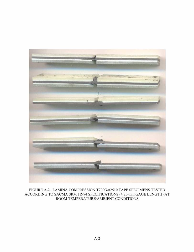
FIGURE A-2. LAMINA COMPRESSION T700G/#2510 TAPE SPECIMENS TESTED ACCORDING TO SACMA SRM 1R-94 SPECIFICATIONS (4.75-mm GAGE LENGTH) AT
ROOM TEMPERATURE/AMBIENT CONDITIONS
A-2

FIGURE A-3. LAMINA COMPRESSION T700G/#2510 TAPE SPECIMENS TESTED ACCORDING TO CEN prEN 2850-B/AMS SPECIFICATIONS (12.5-mm GAGE LENGTH)
AT 82ºC/WET CONDITIONS
A-3

FIGURE A-4. LAMINA COMPRESSION T700G/#2510 TAPE SPECIMENS TESTED
ACCORDING TO SACMA SRM 1R-94 SPECIFICATIONS (4.75-mm GAGE LENGTH) AT 82ºC/WET CONDITIONS
A-4

FIGURE A-5. LAMINA COMPRESSION T300/E-765 FABRIC SPECIMENS TESTED ACCORDING TO CEN prEN 2850-B/AMS SPECIFICATIONS (12.5-mm GAGE LENGTH)
AT ROOM TEMPERATURE/AMBIENT CONDITIONS
A-5

FIGURE A-6. LAMINA COMPRESSION T300/E-765 FABRIC SPECIMENS TESTED ACCORDING TO SACMA SRM 1R-94 SPECIFICATIONS (4.75-mm GAGE LENGTH) AT
ROOM TEMPERATURE/AMBIENT CONDITIONS
A-6

FIGURE A-7. LAMINA COMPRESSION T300/E-765 FABRIC SPECIMENS TESTED ACCORDING TO CEN prEN 2850-B/AMS SPECIFICATIONS (12.5-mm GAGE LENGTH)
AT 82ºC/WET CONDITIONS
A-7

FIGURE A-8. LAMINA COMPRESSION T300/E-765 FABRIC SPECIMENS TESTED ACCORDING TO SACMA SRM 1R-94 SPECIFICATIONS (4.75-mm GAGE LENGTH) AT 82ºC/WET CONDITIONS
A-8

FIGURE A-9. LAMINATE COMPRESSION SPECIMENS FROM 25/50/25 TAPE LAMINATE TESTED ACCORDING TO SACMA SRM 3-94 SPECIFICATIONS
(END-LOADED) AT ROOM TEMPERATURE/AMBIENT CONDITIONS
A-9

FIGURE A-10. LAMINATE COMPRESSION SPECIMENS FROM 25/50/25 TAPE LAMINATE TESTED ACCORDING TO ASTM D 6484 (SHEAR-LOADED) AT ROOM
TEMPERATURE/AMBIENT CONDITIONS
A-10

FIGURE A-11. LAMINATE COMPRESSION SPECIMENS FROM 25/50/25 TAPE LAMINATE TESTED ACCORDING TO SACMA SRM 3-94 SPECIFICATIONS
(END-LOADED) AT 82ºC/WET CONDITIONS
A-11

FIGURE A-12. LAMINATE COMPRESSION SPECIMENS FROM 25/50/25 TAPE LAMINATE TESTED ACCORDING TO ASTM D 6484 (SHEAR-LOADED)
AT 82ºC/WET CONDITIONS
A-12

FIGURE A-13. LAMINATE COMPRESSION SPECIMENS FROM 50/40/10 TAPE LAMINATE TESTED ACCORDING TO SACMA SRM 3-94 SPECIFICATIONS
(END-LOADED) AT ROOM TEMPERATURE/AMBIENT CONDITIONS
A-13

FIGURE A-14. LAMINATE COMPRESSION SPECIMENS FROM 50/40/10 TAPE LAMINATE TESTED ACCORDING TO ASTM D 6484 (SHEAR-LOADED) AT
ROOM TEMPERATURE/AMBIENT CONDITIONS
A-14

FIGURE A-15. LAMINATE COMPRESSION SPECIMENS FROM 50/40/10 TAPE LAMINATE TESTED ACCORDING TO SACMA SRM 3-94 SPECIFICATIONS
(END-LOADED) AT 82ºC/WET CONDITIONS
A-15

FIGURE A-16. LAMINATE COMPRESSION SPECIMENS FROM 50/40/10 TAPE LAMINATE TESTED ACCORDING TO ASTM D 6484 (SHEAR-LOADED) AT
82ºC/WET CONDITIONS
A-16

FIGURE A-17. LAMINATE COMPRESSION SPECIMENS FROM 25/50/25 FABRIC LAMINATE TESTED ACCORDING TO SACMA SRM 3-94 SPECIFICATIONS
(END-LOADED) AT ROOM TEMPERATURE/AMBIENT CONDITIONS
A-17

FIGURE A-18. LAMINATE COMPRESSION SPECIMENS FROM 25/50/25 FABRIC LAMINATE TESTED ACCORDING TO ASTM D 6484 (SHEAR-LOADED) AT
ROOM TEMPERATURE/AMBIENT CONDITIONS
A-18

FIGURE A-19. LAMINATE COMPRESSION SPECIMENS FROM 25/50/25 FABRIC LAMINATE TESTED ACCORDING TO SACMA SRM 3-94 SPECIFICATIONS
(END-LOADED) AT 82ºC/WET CONDITIONS
A-19
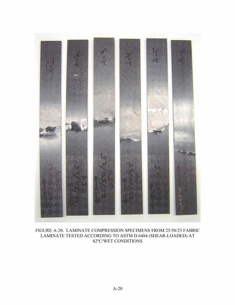
FIGURE A-20. LAMINATE COMPRESSION SPECIMENS FROM 25/50/25 FABRIC LAMINATE TESTED ACCORDING TO ASTM D 6484 (SHEAR-LOADED) AT
82ºC/WET CONDITIONS
A-20

FIGURE A-21. LAMINATE COMPRESSION SPECIMENS FROM 40/20/40 FABRIC LAMINATE TESTED ACCORDING TO SACMA SRM 3-94 SPECIFICATIONS
(END-LOADED) AT ROOM TEMPERATURE/AMBIENT CONDITIONS
A-21

FIGURE A-22. LAMINATE COMPRESSION SPECIMENS FROM 40/20/40 FABRIC LAMINATE TESTED ACCORDING TO ASTM D 6484 (SHEAR-LOADED) AT
ROOM TEMPERATURE/AMBIENT CONDITIONS
A-22

FIGURE A-23. LAMINATE COMPRESSION SPECIMENS FROM 40/20/40 FABRIC LAMINATE TESTED ACCORDING TO SACMA SRM 3-94 (END-LOADED) AT
82ºC/WET CONDITIONS
A-23

FIGURE A-24. LAMINATE COMPRESSION SPECIMENS FROM 40/20/40 FABRIC LAMINATE TESTED ACCORDING TO ASTM D 6484 (SHEAR-LOADED) AT
82ºC/WET CONDITIONS
A-24

FIGURE A-25. IN-PLANE SHEAR SPECIMENS FROM FOUR-PLY TAPE LAMINATE
TESTED AT ROOM TEMPERATURE/AMBIENT CONDITIONS
A-25

FIGURE A-26. IN-PLANE SHEAR SPECIMENS FROM EIGHT-PLY TAPE LAMINATE TESTED AT ROOM TEMPERATURE/AMBIENT CONDITIONS
A-26
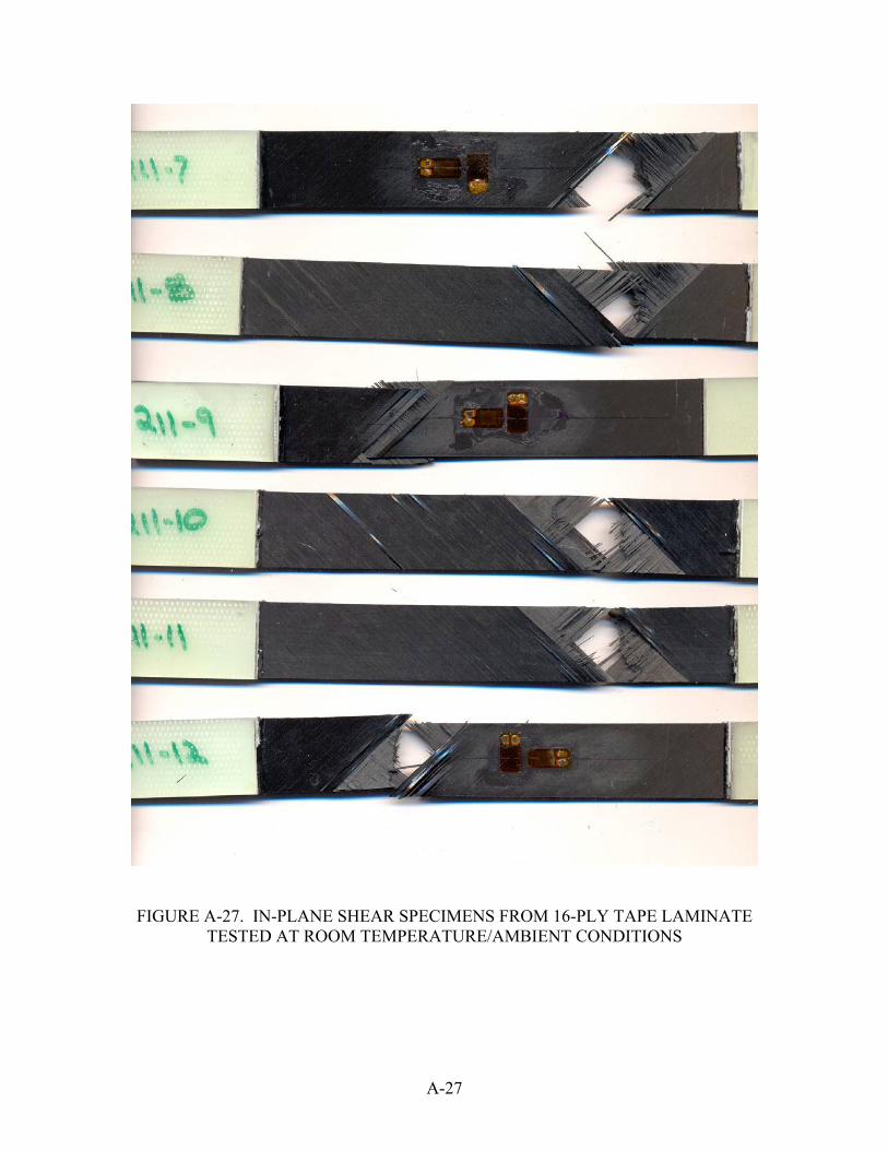
FIGURE A-27. IN-PLANE SHEAR SPECIMENS FROM 16-PLY TAPE LAMINATE TESTED AT ROOM TEMPERATURE/AMBIENT CONDITIONS
A-27

FIGURE A-28. IN-PLANE SHEAR SPECIMENS FROM FOUR-PLY TAPE LAMINATE TESTED AT 82ºC/WET CONDITIONS
A-28

FIGURE A-29. IN-PLANE SHEAR SPECIMENS FROM EIGHT-PLY TAPE LAMINATE TESTED AT 82ºC/WET CONDITIONS
A-29

FIGURE A-30. IN-PLANE SHEAR SPECIMENS FROM 16-PLY TAPE LAMINATE TESTED AT 82ºC/WET CONDITIONS
A-30

FIGURE A-31. IN-PLANE SHEAR SPECIMENS FROM FOUR-PLY FABRIC LAMINATE
TESTED AT ROOM TEMPERATURE/AMBIENT CONDITIONS
A-31

FIGURE A-32. IN-PLANE SHEAR SPECIMENS FROM EIGHT-PLY FABRIC LAMINATE
TESTED AT ROOM TEMPERATURE/AMBIENT CONDITIONS
A-32

FIGURE A-33. IN-PLANE SHEAR SPECIMENS FROM FOUR-PLY FABRIC LAMINATE
TESTED AT 82ºC/WET CONDITIONS
A-33

FIGURE A-34. IN-PLANE SHEAR SPECIMENS FROM EIGHT-PLY FABRIC LAMINATE
TESTED AT 82ºC/WET CONDITIONS
A-34